a method for matching fractured surfaces using shadow...
TRANSCRIPT

Maerz, N. H., and Hilgers, M. C., 2010. A method for matching fractured surfaces using shadow profilometry. Third International Conference on Tribology and Design 2010, May 11-13, 2010, Algarve, Portugal, pp. 237-248.
A Method for Matching Fractured Surfaces Using Shadow Profilometry
Norbert H. Maerz1 & Michael C Hilgers2 1Rock Mechanics and Explosives Research Center, Missouri University of Science and Technology, USA. 2Department of Information Science and Technology, Missouri University of Science and Technology, USA.
Abstract
Characterization of fractured surfaces is of interest to forensic scientists because the measurements can be used to investigate if two fractured surfaces have originated from a single common item, thus allowing the scientists to reconstruct shattered objects and structures. Fracture surfaces of object fragments that failed in tension under load or were torn apart because of explosive forces will have essentially matching surfaces. This paper presents an inexpensive technique for constructing a digital image of a three dimensional surface via two dimensional slices of very small objects using shadow profilometry. This method preserves minor details so that measurements can be made to characterize the each surface and calculate the likelihood that the two surfaces were disjointed. Samples were created by using a load frame to pull apart round, square, and rectangular rods of various materials such as high and low carbon steel, aluminium, brass, and copper. Other samples were created by blasting. Various methods and algorithms utilizing optical microscopy, shadow profilometry, and digital image processing were developed to characterize two fracture surfaces to determine if they originated from a single common object.
Keywords: surface roughness, surface characterization, shadow profilometry, forensic investigations

1 Introduction
1.1 Matching disjointed surfaces
Following disasters caused by explosions or other violent crashes, investigators try to re-assemble original structures from pieces of ripped metal to aid in the determination of the cause of the disaster. Typically there are large numbers of fragments involved in the reconstruction, and not all can be easily fitted together. In many cases it is not possible to determine whether two objects fit together or not. Material failure tends to be somewhat plastic rather than perfectly brittle, making the task more difficult. However fractured surfaces will match at least on the micro level, in a probabilistic sense.
Surface characterization is inherently 3-dimensional in nature. Intuitively, the identifiable features of a surface include its pits, peaks, scraps and so forth. Characterization of a surface requires measuring its texture or roughness so that its discrete features can be better defined.
1.2 Profilometry Methods
Profilometry is a method of using some means to create a cross-section of a surface or surface profile. Mechanical profilometry is a time honoured method of measuring surface profiles, but is increasingly difficult to do on very small surfaces. LADAR is (LAser Detection And Ranging) is new technology that can accurately map surfaces, but requires very expensive equipment, and still has limitations on the size of surfaces that can be scanned [2, 3]. Shadow profilometry is the most efficient and scale independent method available for 3-D characterization [1].
Shadow profilometry is a technique in which an edge of light/shadow is used to trace a surface profile. Multiple profiles produced by moving laterally across a fragment can be used to create a 3-D surface. The principle is that if one creates a plane of light or shadow and intersects it with an undulating surface at an angle of 45º, then the resultant line of intersection follows the topography of the surface and creates a linear profile. To understand this technique better, consider the shadow cast by straight edge on a surface. If the surface is flat then the edge of the shadow will remain straight, but if the surface has an irregularity, such as a divot, the shadow’s edge will have a corresponding curve. Deeper divots will result in more pronounced curvature in the shadow.
A demonstration of a shadow edge is given in Fig. 1. Historically, this principle is put forth by the Schmaltz microscope [4]. It has been used in the mining industry to measure the roughness of rock surfaces to predict their frictional resistance to shearing movement [1]. The particular focus of this investigation is to extend this method to a smaller scale (roughness amplitudes of less than 0.1 mm) suitable for forensic analysis.

Figure 1: Principle of shadow profilometry highlighting the topography of a corrugated cardboard surface (upper left). Shadow (upper right) is identified (lower right) and the edge is isolated creating a linear profile (lower left). The same principle can be exploited using laser striping [5, 6]. Multiple laser lines can be used to get better coverage on the surface (Fig. 2). However, laser lines have a finite width, and because of laser speckle, cannot be used at small scales (measuring amplitudes of less than 2 mm). Profiles produced by shadow edges on the other hand enjoy a certain degree of scale invariance and can be used on very small objects.
Although the shadow edge can only reveal one profile at a time, multiple profiles can be generated by moving the shadow across the surface while acquiring successively images. These images can be combined to create a 3-D surface reconstruction and viewed as a wireframe approximation of a surface.
1.3 Surface reconstruction
Surfaces have been reconstructed in other settings from specific shadow data, such as looking at the shapes of shadows cast by the surface [7], or from the movement of shadows as a light follows a known trajectory above the object [8] and from around the object [9]. Research has also gone into reconstructing surfaces from contours in a family of cross-sectional images [10]. These research projects have had a wide range of success in generating the overall shape and large features of an object, have had little to no success in reconstructing the small-scale, fine features

Fig. 2. Example of profiling of a prepared concrete surface using laser striping hardware [5, 6]. (roughness) of these objects. These minor features play a significant role in roughness calculations and thereby in determining whether two pieces fit together.
2 System hardware
This system was developed with inexpensive off-the-shelf hardware, and is shown in Figure 3. A sample holder is used to secure the samples. It is mounted on a linear stage, set on top of a scissor jack for up and down movement. A manually adjustable tilt stage is added to help with levelling the sample. The shadow profile is achieved by using a fiber optic line light guide and a straightedge (black painted razor blade), mounted in a custom-designed bracket (Figure 4). The bracket holds the light at a 45 degree angle, and the shadow edge generator at an appropriate position and orientation. The light guide has a fiber optic tube which goes back to a variable intensity light source. The straightedge must be lowered as closely to the sample surface as possible to create a crisp shadow edge. A light baffle is added to prevent diffuse reflected light from weakening the shadow edge. Figure. 5 shows an example of a shadow edge profile, with and without the addition of the light baffle.
For imaging, a microscope, a camera, and a computer are required. The microscope selected is an Infinity Infivar continuous focus system that could resolve down to a field of about 0.2 mm. A Sony XCD-SX900 monochrome camera is used because of it high resolution and square pixels (1280 by 960), its non-interlaced (progressive scan) image, and its digital interface (firewire) that negates the need for digitizing hardware and software. The computer for this system is a Sony Vaio laptop computer. It is used because it has firewire input capability.

Figure 3: Left: Imaging setup (top down) show camera, microscope, light guide, and sample holding equipment with fiber optic light source to the left. Right: (from bottom) scissor lift, tilt stage, linear stage, tilting sample holder, and line light source and guide.

Figure 4: Fiber optic line light guide and shadow edge generator over the sample holder set under the mounting bracket. The microscope objective is visible at the top.
Figure 5: Shadow edge of prepared sample without and with light baffle.
3 System software
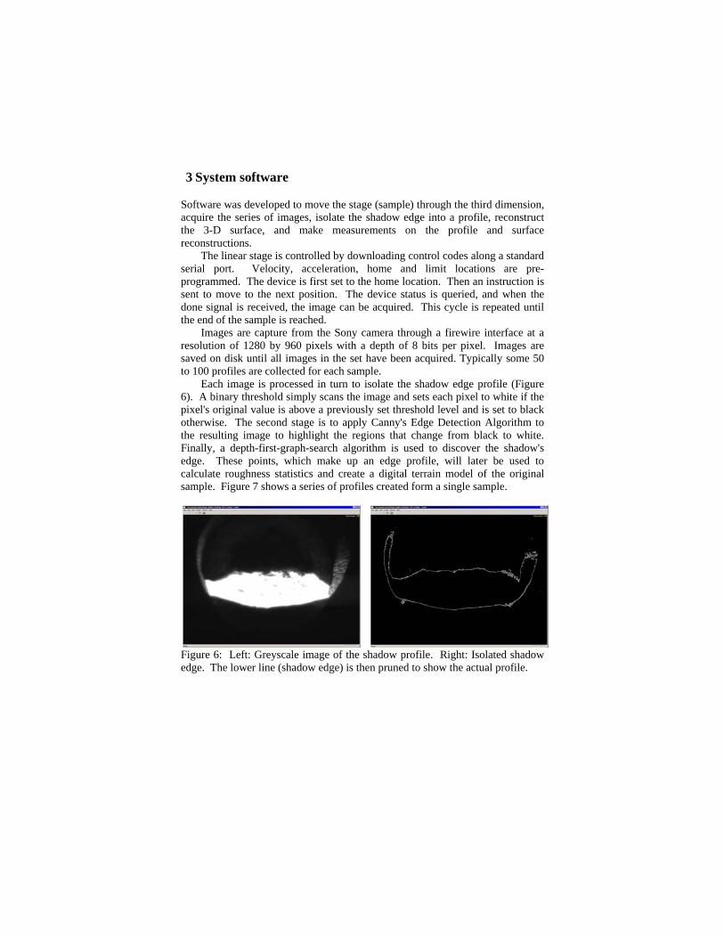
Software was developed to move the stage (sample) through the third dimension, acquire the series of images, isolate the shadow edge into a profile, reconstruct the 3-D surface, and make measurements on the profile and surface reconstructions. The linear stage is controlled by downloading control codes along a standard serial port. Velocity, acceleration, home and limit locations are pre-programmed. The device is first set to the home location. Then an instruction is sent to move to the next position. The device status is queried, and when the done signal is received, the image can be acquired. This cycle is repeated until the end of the sample is reached. Images are capture from the Sony camera through a firewire interface at a resolution of 1280 by 960 pixels with a depth of 8 bits per pixel. Images are saved on disk until all images in the set have been acquired. Typically some 50 to 100 profiles are collected for each sample. Each image is processed in turn to isolate the shadow edge profile (Figure 6). A binary threshold simply scans the image and sets each pixel to white if the pixel's original value is above a previously set threshold level and is set to black otherwise. The second stage is to apply Canny's Edge Detection Algorithm to the resulting image to highlight the regions that change from black to white. Finally, a depth-first-graph-search algorithm is used to discover the shadow's edge. These points, which make up an edge profile, will later be used to calculate roughness statistics and create a digital terrain model of the original sample. Figure 7 shows a series of profiles created form a single sample.
Figure 6: Left: Greyscale image of the shadow profile. Right: Isolated shadow edge. The lower line (shadow edge) is then pruned to show the actual profile.

Figure 7: of 15 line
4 Testi
Various dtesting thbars of vaand coppesamples wripped apby machi
5 2-D (
Linear prconsists ofrom eacamplitudemean andmeasuresindex, fra Usintechniquea significsurfaces s Figurusing ANIn these tcommon surface oconclusio
Left: Surfaceear profiles acr
ing samples
different types his system. In earious sizes coer were loadedwere created b
part using shapening one surfa
(linear profi
rofile analysis wof calculating ch sample. Re measuremend square deviat consisted of r
actal dimensiong the multiple es such as Analcant differencestatistically mare 8 and Tabl
NOVA testing otests two pairsfracture surfa
of a sample of on was obtained
e sample of haoss part the sam
s
of samples weeach case matcomposed of higd and failed in tby using steel ped charges. Fi
ace and creating
file) analysis
was used for ththe roughness
Roughness ments such as petion from centrroot mean squan, and others [1profiles of eaclysis of Variane in the roughatch or not. le 1 shows theon surface rougs of surfaces wace) is tested the same size
d in 62 cases.
ardened steel fample.
ere used for thching pairs of sgh carbon and tension to creaplates either shinally, manufag a plaster of P
s
he first level ofs of each of th
easures, defineeak to valley hreline, center liare of the first 1]. ch surface as rence (ANOVA) hness’s of tw
e results of teghness of alumwere tested. E
against each e and material.
ailed in tension
he purpose of dsamples were umild steel, alu
ate matching suhattered with pactured surfaceParis matching
f investigationhe series of p
ed elsewhere height, levellinne average andderivative, rou
eplicates allowto test whether
wo surfaces, i.e
ests trying to mminium rods faEach pair of su
other, and a In 64 scenar
n. Right: Series
developing andused. Rods anduminium, brassurfaces. Blastedoint charges or
es were createdsurface.
. This analysisprofiles derived[1], consist ong depth, rood others. Slopeughness profile
ws the statisticar or not there ise. whether the
match surfacesailed in tensionurfaces (with aagainst anotherrios the correc
s
d d s, d r d
s d f
ot e e
al s e
s n. a r
ct

Table 1. Summary of ANOVA testing 5 pairs of control samples pairs (G2 is a sample number and G2 X and G2 Y indicate opposite sides of the same fracture surface. “Match” indicates that the surfaces have been found to be statistically similar in roughness parameters Ia (average inclination angle), Rp (roughness profile index), Z2 (root mean square of the first derivative), and RMS (root mean square), and Rmax (maximum amplitude). Check mark indicates that surfaces were correctly matched or not matched. Sample pair Ia Rp Z2 RMS G2 X / G2 Y Match √ Match √ Match √ Match √ G8 X / G8 Y Match √ Match √ Match √ Match √ G2 X / G8 Y No-match √ No-match √ No-match √ No-match √ G8 X / G2 Y No-match √ No-match √ No-match √ No-match √ Sample pair Rp Z2 RMS Rmax H4 X / H4 Y Match √ Match √ Match √ Match √ H5 X / H5 Y Match √ Match √ Match √ Match √ H4 X / H5 Y No-match √ No-match √ No-match √ No-match √ H5 X / H4 Y No-match √ No-match √ No-match √ Match X
Sample pair Rp Z2 RMS Rmax H4 X / H4 Y Match √ Match √ Match √ No-match X H5 X / H5 Y Match √ Match √ Match √ Match √ H4 X / H5 Y No-match √ No-match √ No-match √ No-match √ H5 X / H4 Y No-match √ No-match √ No-match √ No-match √
Sample pair Rp Z2 RMS Rmax T3 X, T3 Y Match √ Match √ Match √ Match √ T4 X, T4 Y Match √ Match √ Match √ Match √ T3 X, T4 Y No-match √ No-match √ No-match √ No-match √ T4 X, T3 Y No-match √ No-match √ No-match √ No-match √
Figure 8: Sample G2 matching surfaces, as an example of the samples used in Table 1 (surfaces created in aluminium using static tensile force).
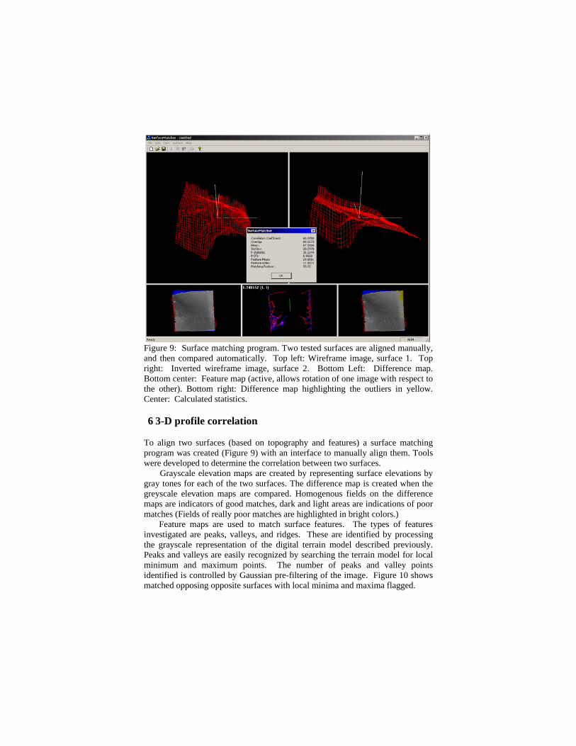
Figure 9: Surface matching program. Two tested surfaces are aligned manually, and then compared automatically. Top left: Wireframe image, surface 1. Top right: Inverted wireframe image, surface 2. Bottom Left: Difference map. Bottom center: Feature map (active, allows rotation of one image with respect to the other). Bottom right: Difference map highlighting the outliers in yellow. Center: Calculated statistics.
6 3-D profile correlation
To align two surfaces (based on topography and features) a surface matching program was created (Figure 9) with an interface to manually align them. Tools were developed to determine the correlation between two surfaces.
Grayscale elevation maps are created by representing surface elevations by gray tones for each of the two surfaces. The difference map is created when the greyscale elevation maps are compared. Homogenous fields on the difference maps are indicators of good matches, dark and light areas are indications of poor matches (Fields of really poor matches are highlighted in bright colors.) Feature maps are used to match surface features. The types of features investigated are peaks, valleys, and ridges. These are identified by processing the grayscale representation of the digital terrain model described previously. Peaks and valleys are easily recognized by searching the terrain model for local minimum and maximum points. The number of peaks and valley points identified is controlled by Gaussian pre-filtering of the image. Figure 10 shows matched opposing opposite surfaces with local minima and maxima flagged.

Figure 10. Extracted features from both sides of a manufactured surface. Top: Green dots are local minima; red dots are local maxima; for the most part the local minima (green dots) from one image match the local maxima (red dots) from the other. (White background indicates positive relief, black negative). Bottom: White lines mark ridges identified by the Canny edge detector.
Within a surface, ridges are areas where the slope drastically changes (downwards to upwards, for example). In image processing, edge detectors are used to segment an image by identifying areas where the difference between pixels is abnormally high. Therefore, using an edge detector to identify ridges in the surface was a natural choice. Specifically, Canny's Edge Detection Algorithm was successfully used to identify ridges in the surface. This is also shown in Figure 10. Feature correlation is accomplished by analyzing the number of corresponding features between surfaces. Features for each surface are projected onto a single plane, and the features from one surface are matched to the closest feature from the other. The mean and standard deviations of the distances between features is reported, a small mean and standard deviation will correspond to closely matching surfaces. The Correlation Coefficient is a standard statistical formula used to determine what proportion of the variations in one data set is explained by variations in another. Correlation values near 1 (100%) signify a good match, while values near -1 and 0 signify an inverse match and no relevant match respectively. The F-Statistic is calculated by assuming one surface is an approximation of the other. Points are randomly selected from the surfaces and are them to calculate the mean-squared error and regression, which are then used to calculate the F-statistic for the model. This statistic can be used to determine the probability of observing two surfaces that match this closely by looking up the corresponding value from an F distribution with 20 numerator degrees of freedom and one denominator degrees of freedom.
7 Summary and conclusions
The methods described in this paper give forensic investigators a novel and unique tool to reconstruct fractured objects by determining if two fractured surfaces are identical mirror images. Shadow profilometery can accurately characterize surfaces 3-D using relatively inexpensive equipment.

Linear profiles can be used by measuring surface roughness. Multiple profiles can be used as replicates, allowing statistical testing to determine if the roughness of the two surfaces in question is the same. A three dimensional surface, modelled as a wireframe, can be further used to determine the compatibility of two surface maps. Two scanned surfaces can be both compared visually, and surface matching statistics can be generated, while rotating the wireframes to optimize alignment of features.
8 Acknowledgments
This work was supported by Federal Bureau of Investigation Laboratory Contract No. J-FBI-02-135, Disjointed Fractured Surface Characterization Using Digital Image. Special thanks to Dr. Robert Koons of the FBI for his guidance on this project. Thanks to Christopher P Walker, Dr. Jeff Thomas, Dr. Greg Galecki, Abhay Sonawane, Jordan Gittemeier, and Jessica Shaffer, and Michael Hellrich for their work on this project.
9 References
[1] Maerz, N. H., Franklin, J. A, and Bennett, C. A., 1990. “Joint Roughness Measurement Using Shadow Profilometry.” Int. J. of Rock Mech. Min. Sci. & Geomech. Abst, 27, pp. 329-343. [2] Kim, H., Haas, C. T., Rauch, A. F., and Browne, C., 2002. “Dimensional Ratios For Stone Aggregates From Three-Dimensional Laser Scans.” [3] Agapakins, J., 1990. “Approaches for Recognition and Interpretation of Workpiece Surface Features Using Structured Lighting”. The International Journal of Robotics Research, 9 (5). [4] Schmaltz, G., 1936. “Technishe Oberflächenkunde.” Springer, Berlin, 286 pp. [5] Maerz, N. H., Chepur, P, Myers, J., J., and Linz, J., 2001a. “Concrete Roughness Measurement Using Laser Profilometry For Fiber Reinforced Polymer Sheet Application.” Transportation Research Record, 1775, pp. 132-139. [6] Maerz, N. H., Nanni, A., Myers, J. J., and Galecki, G., 2001b. “Laser Profilometry For Concrete Substrate Characterization Prior To FRP Laminate Application.” Concrete Repair Bulletin, May-Jun. 2001, pp. 4-8. [7] Daum, M, and Dudek, G., 1998. “On 3-D Surface Reconstruction Using Shape From Shadows.” Computer Vision and Pattern Recognition. [8] Raviv, D., Pao, Y, and Loparo, K., 1989. “Reconstruction of Three Dimensional Surfaces from Two-Dimensional Binary Images.” IEEE Transactions on Robotics and Automation, 5 (5). [9] Seng, T., Len, G., and Chan, K., 1993. “Shape Reconstruction from Shadow and Shading.” Industrial Electronics, Control, and Instrumentation. [10] Ahmed, M., Hemayed, E., Jansing, D., and Farag, A., 1996. “Surface Reconstruction from Serial Cross Sections”. Aerospace Applications Conference, 4, pp. 3-10.