a method for enterprise architecture alignment - middlesex
TRANSCRIPT

Middlesex University Research RepositoryAn open access repository of
Middlesex University research
http://eprints.mdx.ac.uk
Clark, Tony, Barn, Balbir ORCID: https://orcid.org/0000-0002-7251-5033 and Oussena, Samia(2012) A method for enterprise architecture alignment. In: Practice-Driven Research on
Enterprise Transformation : 4th Working Conference, PRET 2012, Gdansk, Poland, June 27,2012. Proceedings. Proper, E, Gaaloul, K, Harmsen, F and Wrycza, S, eds. Lecture Notes inBusiness Information Processing (120) . Springer, pp. 48-76. ISBN 9783642311338. [Book
Section] (doi:10.1007/978-3-642-31134-5_3)
This version is available at: https://eprints.mdx.ac.uk/9571/
Copyright:
Middlesex University Research Repository makes the University’s research available electronically.
Copyright and moral rights to this work are retained by the author and/or other copyright ownersunless otherwise stated. The work is supplied on the understanding that any use for commercial gainis strictly forbidden. A copy may be downloaded for personal, non-commercial, research or studywithout prior permission and without charge.
Works, including theses and research projects, may not be reproduced in any format or medium, orextensive quotations taken from them, or their content changed in any way, without first obtainingpermission in writing from the copyright holder(s). They may not be sold or exploited commercially inany format or medium without the prior written permission of the copyright holder(s).
Full bibliographic details must be given when referring to, or quoting from full items including theauthor’s name, the title of the work, publication details where relevant (place, publisher, date), pag-ination, and for theses or dissertations the awarding institution, the degree type awarded, and thedate of the award.
If you believe that any material held in the repository infringes copyright law, please contact theRepository Team at Middlesex University via the following email address:
The item will be removed from the repository while any claim is being investigated.
See also repository copyright: re-use policy: http://eprints.mdx.ac.uk/policies.html#copy

A Method for Enterprise Architecture Alignment
Tony Clark1, Balbir S. Barn1, and Samia Oussena2
1 Middlesex University, London, UK2 University of West London, UK
Summary. Business and ICT strategic alignment remains an ongoingchallenge facing organizations as they react to changing requirementsby adapting or introducing new technologies to existing infrastructure.Enterprise Architecture (EA) has increasingly become relevant to thesedemands and as a consequence numerous methods and frameworks haveemerged. However these approaches remain bloated, time-consuming andlacking in precision. This paper proposes a light-weight method for EAcalled LEAP and introduces a language for EA simulation that is il-lustrated with a detailed case study of business change currently beingaddressed by UK higher education institutions.
1 Introduction
Enterprise Architecture (EA) is intended to provide a holistic understanding ofall aspects of a business, connecting the business drivers and the surroundingbusiness environment, through the business processes, organizational units, rolesand responsibilities, to the underlying IT systems that the business relies on[18]. In addition to presenting a coherent explanation of the what, why and how
of a business, EA aims to support speci�c types of business analysis including:alignment between business functions and IT systems; business change describingthe current state of a business (as-is) and a desired state of a business (to-be); maintenance of systems; checks for quality assurance and compliance; andstrategic planning [9, 25, 20, 4, 13]. Alignment between business and IT strategyhowever remains one of the most pressing concerns [6].
EA has its origins in Zachman's original EA framework [34] but has sinceseen a range of methods introduced along with some speci�c tool modelling lan-guages such as ArchiMate [12]. Emerging methods while purporting to addressEA requirements have themselves posed questions about their e�cacy. Becausemethods have largely been located as part of EA frameworks they do not readilyprovide the means by which to easily address the need to understand how tochange an EA to meet a new requirement. Drilling down, the potential impactand change to an EA required would need to be promulgated as an impact anal-ysis, a sliced view of the EA (of the systems a�ected), a gap analysis of missingfunctions and most importantly an equivalence analysis of an existing systemand proposed changes. Current methods and frameworks that have largely pre-sented layered architectural models do not necessarily lend themselves to thistype of modeling and analysis. Furthermore their bloated and document driven
2 Tony Clark, Balbir S. Barn, and Samia Oussena
nature presents additional issues of complexity and places signi�cant workloadson enterprise architects and those tasked with managing systems in large or-ganization. In section 2 we discuss and review the various EA methods andframeworks currently available.
Another aspect that has potential to in�uence the use of an EA to addressuse cases such as measuring alignment between business and IT, business changeor integration of new systems is the di�erent architectural styles that may beprevalent in a single organization. Several di�erent styles of architecture arepossible. A Service Oriented Architecture (SOA) involves the publication of log-ically coherent groups of business functionality as interfaces, that can be usedby components using synchronous or asynchronous messaging. An alternativestyle, argued as reducing coupling between components and thereby increasingthe scope for component reuse, is Event Driven Architecture (EDA) wherebycomponents are event generators and consumers. An important di�erence be-tween SOA and EDA is that the latter generally provides scope for ComplexEvent Processing (CEP) where the business processes within a component aretriggered by multiple, possibly temporally related, events. In SOA there is nonotion of relating the invocation of a single business process to a condition hold-ing between the data passed to a collection of calls on one of the component'sinterfaces. As described in [19] and [26], complex events can be the basis fora style of EA design. EDA replaces interfaces with events that trigger organi-zational activities. This creates the �exibility necessary to adapt to changingcircumstances and makes it possible to generate new processes by a sequence ofevents [22]. The relationship between event driven SOA and EA is described in[2] where a framework is proposed that allows enterprise architects to formulateand analyze research questions including `how to model and plan EA-evolutionto SOA-style in a holistic way' and `how to model the enterprise on a formalbasis so that further research for automation can be done.' Our claim is thatsystem architectures should be based on both EDA and SOA.
Technologies for EA need to support a wide spectrum of business conceptsand use-cases. When designing such technologies there are essentially two ap-proaches: top-down or analytic and bottom-up or synthetic. The former charac-teristically identi�es all potentially distinct categories of feature from the domainwith the goal of equipping the user with a richly diverse collection of elementswith which to express their models. The approach guarantees to provide a suf-�ciently expressive language at the expense of precision and orthogonality. Thelatter characteristically identi�es a precisely de�ned collection of orthogonal con-cepts with associated semantics; the goal is to achieve precision with respect to acollection of de�ned use-cases, as opposed to the the more holistic, but imprecise,top-down approach.
There is safety in the analytic approach, it is guaranteed to be completemostly because of its ambiguity and rich collection of features. However thissafety is misleading since the resulting language is not amenable to mechanicalprocessing and rigorous analysis. Therefore, top-down languages are forever con-

A Method for Enterprise Architecture Alignment 3
signed to the early stages of system analysis and design where so-called sketching
is an important modelling technique.So how dangerous is the synthetic approach? Certainly it is almost guaran-
teed to be incomplete since the design of the language must be contextualizedwith particular use-cases. However, this might lead to a language that is good
enough for most cases, and as such will have engineering bene�ts that far out-weigh those of a sketching language. In addition, a synthetic language providesa �rm basis for iterative language development through the incremental analysisof new use-cases.
EA languages are currently exclusively top-down. They are large and impre-cise and therefore almost guaranteed to support any interpretation of a businessand associated EA use-case. Typically, an EA language makes distinctions be-tween di�erent views of a business, for example separating business, applicationand technology layers. The result is a very large number of suspiciously similarfeatures. Our proposal is that this is not necessary, and that the multiplicity offeature variety and separation of views is bogus, at least fundamentally1.
This paper validates the claim that EA technologies should be synthetic byintroducing and using a technology called LEAP to analyse a problem facedby UK universities. The case study involves the speci�cation of an idealizedsystem that meets a new organizational regulation, then shows how the currentIT systems can be used to implement the system and �nally describes a processby which the two architectures can be aligned. It is precisely because LEAPis a synthetic operational language for architecture simulation that the usercan have con�dence in the alignment, in contrast to other enterprise modellingtechnologies. The approach has been used to describe concrete IT systems withinour own organization and to indicate appropriate modi�cations necessary tomeet new regulations. Our contribution claim is that LEAP represents a novelapproach to EA in that it is a simple, precise and executable technology thato�ers a di�erent approach to EA analysis with the advantages that come withthe ability to analyze and simulate an architecture.
2 Related work on EA methods
The nature of EA, that is, its breadth, the range of organizational impact andthe inherent complexity of operating at multiple levels (business through todeployment) and technology variations means that it is di�cult to arrive atspeci�c understanding of what methodologies are available and the extent of theirutilization. As Riege et al point out: `Although there are isolated EA methods
taking the situation of application into account,..., there is no overall landscape
of EA methods available' [25, :p389]. In addition, the practitioner nature ofEA also means that well documented methods are di�cult to access. In orderto establish the current availability and literature surrounding EA methods,key word searches `Enterprise Architecture Method ' were conducted in Google
1 How it is presented to a business user is entirely a di�erent matter.

4 Tony Clark, Balbir S. Barn, and Samia Oussena
Scholar and the ACM/IEEE digital libraries. This section presents an overviewof the current situation and while it is not an exhaustive literature review (thelimitations of the paper and its main focus prevents that) it does allow the readeran insight into the state of the art.
Much literature has concentrated on providing descriptions of a number ofarchitecture frameworks. Usefully Steen et al point out: `Frameworks provide
structure to the architectural descriptions by identifying and sometimes relat-
ing di�erent architectural domains and the modelling techniques associated with
them' [28, :p6]. Some of the more popular and widely disseminated EA frame-works include:
Zachman's Framework that provides a logical structure for classifying andorganizing representations of an EA relevant to speci�c stakeholders in termsof 36 di�erent types of views [34];
The Reference Model for Open Distributed Processing (RM-ODP) isan ISO/ITU Standard (ITU, 1996) that de�nes a framework for architecturespeci�cation of large distributed systems using �ve viewpoints on a systemand its environment: enterprise, information, computation, engineering andtechnology. The theoretical basis of the RM-ODP model resides in objectoriented principles and service oriented speci�cation and the mapping of thelevels to implementation objects [15, 24];
The Open Group's framework TOGAF [27] and related frameworks forthe Department of Defense ( DODAF [33]), Federal processing (FEAF),UK Ministry of Defence (MODAF) [3] provides over-arching structures forsupporting a consistent approach for standardizing, planning, analyzing andmodelling of architectural system components.
Regardless of the speci�cs of the framework, as Tang et al note there are commonde�ciencies such as: (1) the level of detail required in an architecture model is notgenerally speci�ed; (2) support, speci�cation and management of non-functionalrequirements is lacking and (3) software con�guration modelling is also generallylacking [29]. Although architecture includes notions of design, the objective ofarchitecture is di�erent from design but there are a lack of guidelines to addressthe case when architectural activity moves into detailed design.
The frameworks discussed above claim independence of any speci�c method.In addition to the availability of these frameworks, a number of methods aimedat delivering techniques, languages and tools to support EA have also been de-veloped. The ADM method underpinning TOGAF is one exception. Methodshave focused on speci�c aspects of business and IT alignment [30, 31] (an oftcited requirement [6]) or they have provided a means of providing analysis toolsfor understanding EA changes and impact [17, 16]. Of note also is the UN/CE-FACT modelling method - a UML based approach to design business servicesthat are focused on collaboration with external organizations [14]. Like [11]thismethod introduces the notion of the extended enterprise architecture that in-cludes external system components (located in other organizations) that requirecollaboration.

A Method for Enterprise Architecture Alignment 5
There are examples of methods that have a more generic EA purpose. Thesemethods do not focus on typical use cases for EA, instead they are aimed ataddressing the design gap introduced earlier and identi�ed by [29]. An earlyexample is Memo [10] an EA method that introduces a range of visual mod-elling languages supporting multiple views. The method provides an integratedprocess model. Some of the approaches proposed could be argued to have beensuperseded by advances in business process modelling notably with the adventof BPMN (Business Process Modelling Notation) and service oriented architec-tures. Pereira and Sousa [23] introduce a method that is overlayed on top of theZachman framework and suggests how speci�c techniques can be used to developeach of the 36 viewpoints. Integration of artifacts produced for the viewpointsis also suggested. Support for Event modelling is not immediately clear in thismethod. The SOMA method developed by Arsanjani et al for IBM is an end-endsoftware development life-cycle method that assumes a service oriented architec-ture style for EA. The method uses concepts of component based design and goaloriented modelling as well as established techniques such as use case modellingto support the design and implementation of EA solutions [1]. While the lan-guage and concepts underpinning SOMA have some similarity with the methodand technology proposed in this paper, we note that consistent with all themethods reviewed here, there is not immediate clarity on how event modellingis integrated and supported in these methods.
The range and variation of methods in terms of focus and scope stronglysupports the case proposed by Riege et al that there is no method that �ts allthe requirements for EA and instead there is a need for a method engineering ap-proach [25]. They identify three broad contingency factors that should in�uencethe target focus for EA methods: Adoption of advanced architectural paradigmsand modelling capabilities; Deployment and monitoring of EA data and servicesand Organizational penetration of EA. We argue that that methods also needto ensure that they address the key use cases for EA such as business and ITalignment.
Our claim is that many EA use-cases can be addressed using a preciselyde�ned synthetic language compared to the imprecise analytic technologies cur-rently available. To validate this claim we have constructed a technology calledLEAP that is brie�y introduced in section 3 where it is compared with a leadingEA technology. We have applied LEAP to a number of real-world case studiessuch as that described in section 6, however because these become rather large,section 4 describes a complete LEAP application using a simple example. Wedo not claim that LEAP will support every EA use-case, however our aim toaddress a series of use-cases and incrementally extend LEAP. This paper arguesthat LEAP represents a practical technology for Architecture Alignment andour approach is de�ned in section 5.

6 Tony Clark, Balbir S. Barn, and Samia Oussena
3 LEAP
The LEAP language proposes that EA is fundamentally about representing andanalyzing data-rich and highly-structured executable systems at di�erent levelsof abstraction. It has been designed as a synthetic language where distinctionsbetween many business concepts are deemed fundamentally irrelevant (domainspeci�c presentation issues being viewed as perfectly respectable sugar). The keyconcepts in LEAP are:
component A component is the key structuring concept in LEAP and canbe used to represent entities such as physical systems, roles, logical sys-tems, transient elements, and organizational units. Components encapsulatedata, behaviour, conditions such as business directives and goals, and can benested. Components are intended to support a process of step-wise re�ne-ment where a business can be expressed as a single component at a high-levelof abstraction and where re�nement develops a graph of sub-components.
data Each component de�nes models of data; shared models support informa-tion communication between components. Data is highly structured, includ-ing lists and records, to facilitate declarative pattern matching.
functions LEAP is a functional language. Functions can be attached to com-ponents to represent business processes and can be used at any level toparameterize over language features. For example, parameterizing over com-ponents supports template patterns.
messages LEAP execution is performed in terms of messages between compo-nent ports. Messages are de�ned in port interfaces and bear model data.Execution strategies for both SOA and EDA are supported through the con-struction and use of component architectures based on the same fundamentalconcepts.
rules Component behaviour can be speci�ed in terms of rules that matchagainst data in the local database and messages arriving at the component'sports. Rules facilitate complex event processing since a rule may rely onreceiving multiple unordered interrelated messages and database changes ofarbitrary complexity. Where appropriate, rule collections can be expressedusing state machines within components.
conditions Business goals and directives can be expressed using invariants overthe state of a component and its sub-components. Component behaviour canbe expressed in terms of pre and post-conditions.
LEAP has a precise semantics in the form of an operational implementationand an associated tool for graphical display and simulation. Our claim is thatthe features above are necessary and su�cient for a wide range of EA use-cases,and there they are not su�cient, a conservative extension will su�ce.
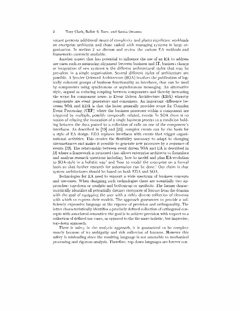
Figure 1 shows a comparison between ArchiMate concepts and LEAP con-cepts. We have chosen ArchiMate because it is arguably the most developedEA notation. The table shows that ArchiMate includes a large number of dif-ferent elements that can be mapped onto a smaller number of LEAP elements.In fact, ArchiMate includes more elements that those shown because several of
A Method for Enterprise Architecture Alignment 7
Archimate Concept LEAP Concept
Actor Component
Application Layer Components
Artifact Data Model
Behaviour Operation,rule, transition
Business Function Operation, rule, transition
Business Layer Components
Business Process Operation, rule, transition
Business Service Operation, rule, transition
Collaboration Components
Collective Behaviour Components
Communication Path Connections
Concept Component,Class
Contract Invariant
Device Component
External Perspective LEAP Model
Individual Behaviour Component
Interaction Mesage
Interface Interface
Internal Perspective LEAP Model
Meaning Semantics
Network Component
Product Data Model
Representation Data Model
Role Component
Software Component
Technology Layer Components
Value ?
Fig. 1: Comparison of Archimate and LEAPthe concepts occur as distinct elements in di�erent layers. Our claim is that thismapping provides evidence that EA languages, and ArchiMate in particular, in-cludes redundancy that is di�cult to analyze without mapping to a languagewith precise semantics.
It should be stated that LEAP does not claim to be an Architecture Descrip-tion Language, although it shares many features with technologies for ADL.Features of LEAP can be used to model both physical and logical aspects of asystem including information, roles and organizational units. Furthermore, al-though LEAP has an operational semantics, there is no support for expressingcomplex features such as real-time.
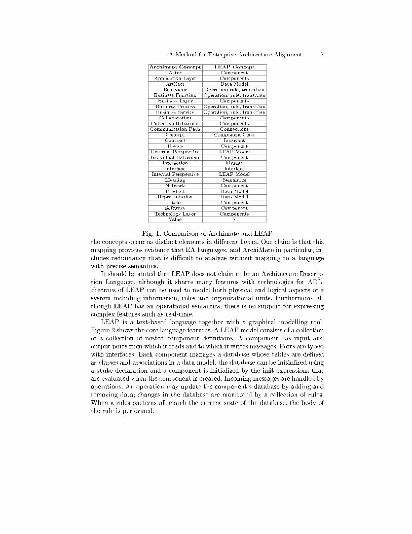
LEAP is a text-based language together with a graphical modelling tool.Figure 2 shows the core language features. A LEAP model consists of a collectionof a collection of nested component de�nitions. A component has input andoutput ports from which it reads and to which it writes messages. Ports are typedwith interfaces. Each component manages a database whose tables are de�nedas classes and associations in a data model. the database can be initialized usinga state declaration and a component is initialized by the init expressions thatare evaluated when the component is created. Incoming messages are handled byoperations. An operation may update the component's database by adding andremoving data; changes in the database are monitored by a collection of rules.When a rules patterns all match the current state of the database, the body ofthe rule is performed.
8 Tony Clark, Balbir S. Barn, and Samia Oussena
exp ::=cmp
| fun(arg*) exp functions| exp(exp*) applications| var variables| atom ints,strs,bools| state local data| self reference| { exp* } blocks| { bind* } records| [ exp | qual* ] lists| new term extension| term terms| delete term deletion| if exp then exp else exp conditional| replace pattern with term else exp| �nd pattern in exp exp else exp| case exp { arm* } matching| let bind* in exp locals| for pattern in exp { exp } loops| forall pattern in exp { exp } univ quant| exp <- name(exp*) message passingterm ::= name(exp*)arm ::= pattern -> expbind ::= pattern = expqual ::= pattern <- exp | ?exp
cmp ::= componentscomponent [name] { optional nameport* input/output ports[model { element* }] data models[state { term* }] local data[invariants { inv* }] always hold[operations { op* }] methods[rules { rule* }] event processing[init { exp* } initialization(name = exp)* bindings
}port ::=port name[(in|out)]: interface { message }
element ::=class name { (name:type)* }
| assoc name { name type name type }pattern ::=var variables
| name(pattern*) term patterns| atom ints,strs,bools| name = pattern pattern binding| [pattern*] lists| pattern:pattern cons pairs| ? exp predicateop ::= name(arg*) { exp* }rule ::= name : pattern* { exp* }
Fig. 2: LEAP Language4 A Simple LEAP Example
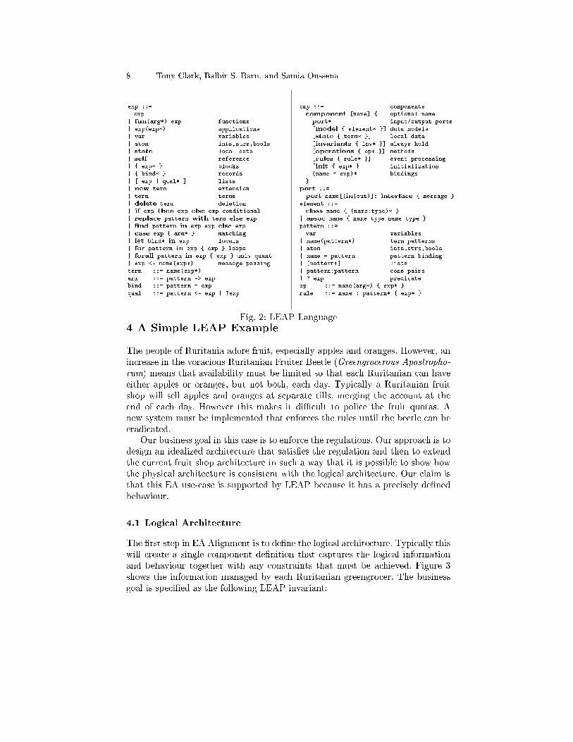
The people of Ruritania adore fruit, especially apples and oranges. However, anincrease in the voracious Ruritanian Fruiter Beetle (Greengrocerous Apostropho-
rum) means that availability must be limited so that each Ruritanian can haveeither apples or oranges, but not both, each day. Typically a Ruritanian fruitshop will sell apples and oranges at separate tills, merging the account at theend of each day. However this makes it di�cult to police the fruit quotas. Anew system must be implemented that enforces the rules until the beetle can beeradicated.
Our business goal in this case is to enforce the regulations. Our approach is todesign an idealized architecture that satis�es the regulation and then to extendthe current fruit shop architecture in such a way that it is possible to show howthe physical architecture is consistent with the logical architecture. Our claim isthat this EA use-case is supported by LEAP because it has a precisely de�nedbehaviour.
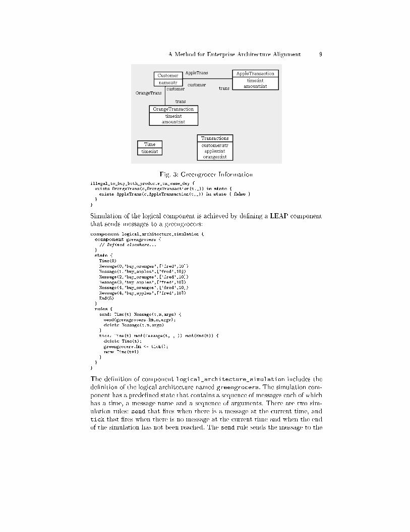
4.1 Logical Architecture
The �rst step in EA Alignment is to de�ne the logical architecture. Typically thiswill create a single component de�nition that captures the logical informationand behaviour together with any constraints that must be achieved. Figure 3shows the information managed by each Ruritanian greengrocer. The businessgoal is speci�ed as the following LEAP invariant:
A Method for Enterprise Architecture Alignment 9
Fig. 3: Greengrocer Informationillegal_to_buy_both_products_on_same_day {exists OrangeTrans(c,OrangeTransaction(t,_)) in state {exists AppleTrans(c,AppleTransaction(t,_)) in state { false }
}}
Simulation of the logical component is achieved by de�ning a LEAP componentthat sends messages to a greengrocers:
component logical_architecture_simulation {component greengrocers {// Defined elsewhere...
}state {Time(0)Message(0,'buy_oranges',['fred',10])Message(1,'buy_apples',['fred',10])Message(2,'buy_oranges',['fred',10])Message(3,'buy_apples',['fred',10])Message(4,'buy_oranges',['fred',10])Message(4,'buy_apples',['fred',10])End(5)
}rules {send: Time(t) Message(t,m,args) {send(greengrocers.in,m,args);delete Message(t,m,args)
}tick: Time(t) not(Message(t,_,_)) not(End(t)) {delete Time(t);greengrocers.in <- tick();new Time(t+1)
}}
}
The de�nition of component logical_architecture_simulation includes thede�nition of the logical architecture named greengrocers. The simulation com-ponent has a prede�ned state that contains a sequence of messages each of whichhas a time, a message name and a sequence of arguments. There are two sim-ulation rules: send that �res when there is a message at the current time, andtick that �res when there is no message at the current time and when the endof the simulation has not been reached. The send rule sends the message to the

10 Tony Clark, Balbir S. Barn, and Samia Oussena
input port of the greengrocer component. The tick rule increments the timeand sends a tick message to the greengrocer. The logical component is de�nedas follows:component greengrocers {model { // As shown in figure Greengrocer Information ... }
invariants { // The illegal_to_buy_both_products_on_same_day condition... }
port in[in]: interface {buy_apples(name:str,amount:int):void;buy_oranges(name:str,amount:int):void;tick():void
}operations {buy_apples(customer,amount) {let c = get_customer(customer); t = time()in new AppleTransaction(t,amount), AppleTrans(c,AppleTransaction(t,amount))
}buy_oranges(customer,amount) { // As above for oranges... }
get_customer(name) { �nd Customer(name) in state else new Customer(name) }time() { �nd Time(t) in state { t } else 0 }tick() { replace Time(t) with Time(t+1) else new Time(1) }addup(l) { case l { [] -> 0; h:t -> h + addup(t) } }
}rules {day: Time(t) {for Customer(name) in state {let oranges = addup([n | OrangeTrans(Customer(name),OrangeTransaction(tt,n)) <- state, ?(tt <= t) ]);
apples = addup([n | AppleTrans(Customer(name),AppleTransaction(tt,n)) <- state, ?(tt <= t) ])in replace Transactions(name,a,o) with Transactions(name,apples,oranges)
else new Transactions(name,apples,oranges)}
}}
}
The port named in can receive messages named buy_apples, buy_oranges andtick. Each message is handled by an operation with the same name. Con-sider buy_apples, it uses the private local operation get_customer to select aterm from the component's database (named state) if it exists or create a newcustomer-term if it does not. The buy_apples operation proceeds by queryingthe database for the current time and then adding two new database terms thatrepresent an apple transaction.
The greengrocer component has a rule named day that is run once perday in order to consolidate the accounts. Rules are checked each time a messagearrives or when the database changes in a component. In this case all the trans-actions for the customer in the given day are added up and a new consolidatedTransactions term is added to the database.
Logical Architectureφ - Execution Traces
Physical Architecture
refine
?
φ- Execution Traces
project
6
Fig. 4: Architecture Re�nement

A Method for Enterprise Architecture Alignment 11
4.2 Re�nement
component in state
greengrocers buy_oranges('fred',10)
greengrocers tick() OrangeTrans(Customer('fred'),OrangeTransaction(0,10)),OrangeTransaction(0,10), Customer('fred')
greengrocers buy_apples('fred',10) Transactions('fred',0,10), Time(1),...
greengrocers tick() AppleTrans(Customer('fred'),AppleTransaction(1,10)),AppleTransaction(1,10),...
greengrocers buy_oranges('fred',10) Transactions('fred',10,10), Time(2),...
greengrocers tick() OrangeTrans(Customer('fred'),OrangeTransaction(2,10)),OrangeTransaction(2,10),Transactions('fred',10,10), Time(2), ...
greengrocers buy_apples('fred',10) Transactions('fred',10,20), Time(3),...
greengrocers tick() AppleTrans(Customer('fred'),AppleTransaction(3,10)), AppleTransaction(3,10),Transactions('fred',10,20), Time(3), ...
greengrocers buy_apples('fred',10) Transactions('fred',20,20), Time(4), ...
greengrocers buy_oranges('fred',10) AppleTrans(Customer('fred'),AppleTransaction(4,10)), AppleTransaction(4,10),Transactions('fred',20,20), Time(4), ...
greengrocers tick() OrangeTrans(Customer('fred'),OrangeTransaction(4,10)),OrangeTransaction(4,10), ...
greengrocers Transactions('fred',30,30), Time(5), ...
Fig. 5: Logical Architecture Execution TraceLEAP has an executable semantics which means that a LEAP model can
be mapped to execution traces. Figure 4 is an overview of the approach forarchitecture alignment. A Logical Architecture, such as that described for Ruri-tanian greengrocers is mapped to execution traces via a semantic function φ.A Physical Architecture is constructed using the real-world systems available tothe organization leading to a collection of physical execution traces. It remainsto show that the physical architecture is complete and consistent. Completenessis achieved by showing that there is a physical trace for every correct logicaltrace and consistency is achieved by showing that every physical trace can beprojected onto a correct logical trace, subject to preserving key information.
Given that LEAP has a precisely de�ned semantics (currently implementedas a tool for executing LEAP models), it would be possible to formally establishthe re�nement criteria. In practice however, it is likely that rigorous inspectionof traces will be su�cient to provide con�dence of correct re�nement. The LEAPtool can produce an XML trace of a model execution. The table shown in �gure 5is a symbolic representation of the output for the greengrocer simulation whereexecution proceeds from top to bottom and repeated state is represented byellipses.
4.3 Physical Architecture
A physical architecture must re�ect the systems available to an organization. AllRuritanian Greengrocers must, by law, implement separate tills for apples andoranges. Therefore, they have separate IT systems that must be consolidated
12 Tony Clark, Balbir S. Barn, and Samia Oussena
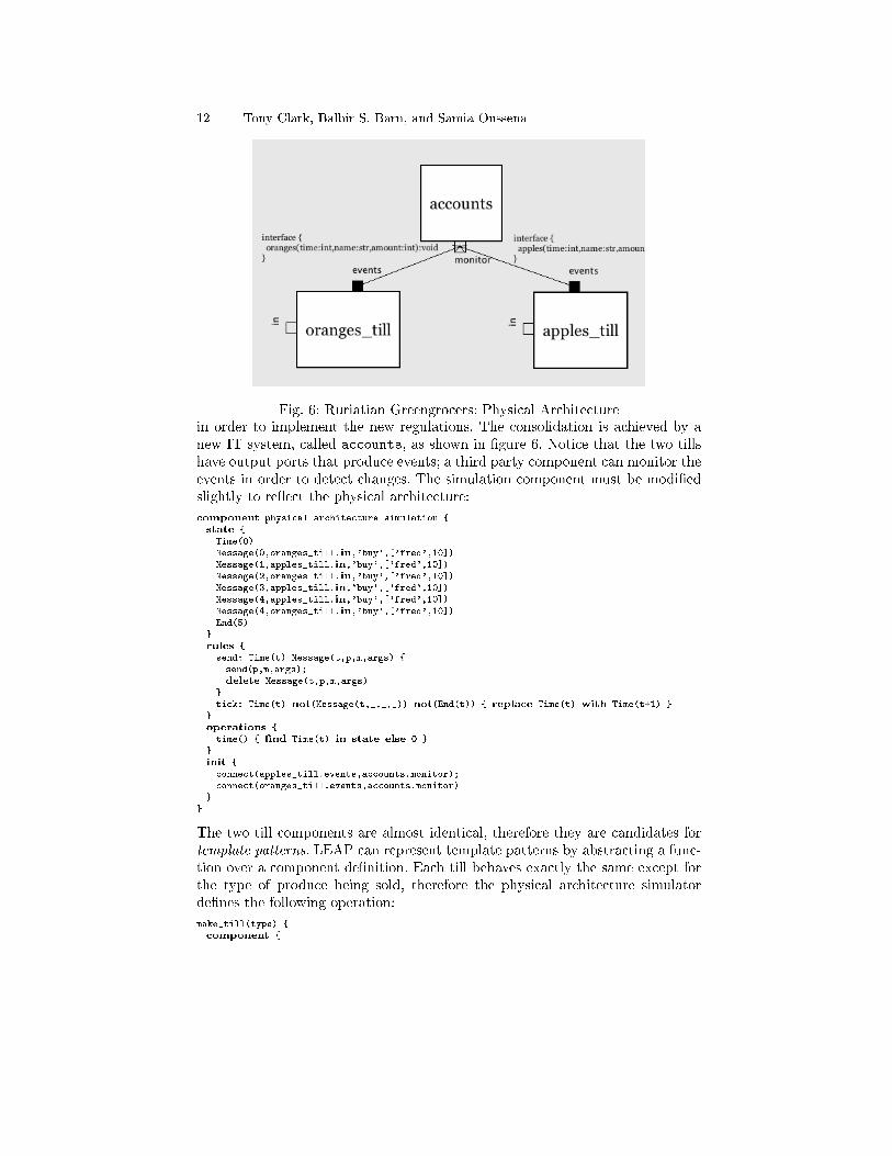
Fig. 6: Ruriatian Greengrocers: Physical Architecturein order to implement the new regulations. The consolidation is achieved by anew IT system, called accounts, as shown in �gure 6. Notice that the two tillshave output ports that produce events; a third party component can monitor theevents in order to detect changes. The simulation component must be modi�edslightly to re�ect the physical architecture:
component physical_architecture_simulation {state {Time(0)Message(0,oranges_till.in,'buy',['fred',10])Message(1,apples_till.in,'buy',['fred',10])Message(2,oranges_till.in,'buy',['fred',10])Message(3,apples_till.in,'buy',['fred',10])Message(4,apples_till.in,'buy',['fred',10])Message(4,oranges_till.in,'buy',['fred',10])End(5)
}rules {send: Time(t) Message(t,p,m,args) {send(p,m,args);delete Message(t,p,m,args)
}tick: Time(t) not(Message(t,_,_,_)) not(End(t)) { replace Time(t) with Time(t+1) }
}operations {time() { �nd Time(t) in state else 0 }
}init {connect(apples_till.events,accounts.monitor);connect(oranges_till.events,accounts.monitor)
}}
The two till components are almost identical, therefore they are candidates fortemplate patterns. LEAP can represent template patterns by abstracting a func-tion over a component de�nition. Each till behaves exactly the same except forthe type of produce being sold, therefore the physical architecture simulatorde�nes the following operation:
make_till(type) {component {

A Method for Enterprise Architecture Alignment 13
model {class Customer { name:str }class Transaction { type:str; time:int; amount:int }assoc Trans { customer Customer trans Transaction }
}port in[in]: interface {buy(name:str,amount:int):void
}port events[out]: interface {buy(type:str,time:int,name:str,amount:int):void
}operations {buy(customer,amount) {let c = get_customer(customer)in {new Transaction(type,time(),amount);new Trans(c,Transaction(type,time(),amount));events <- buy(type,time(),customer,amount)
}}get_customer(name) {�nd Customer(name) in state else new Customer(name)
}}
}}
Now it is possible to create both types of till using the function:
component physical_architecture_simulation {operations {make_till(type) { ... }
}oranges_till = make_till('oranges')apples_till = make_till('apples')...
}
The accounts component monitors the events created by the till components,must consolidate the accounts and must detect fraud when it occurs. The phys-ical de�nition of the new system is as follows:
component accounts {model {class Transactions { customer:str; apples:int; oranges:int }
}port monitor[in]: interface {buy(type:str,time:int,customer:str,amount:int):void
}operations {buy(type,t,customer,amount) {case type {'apples' -> new Apples(t,customer,amount);'oranges' -> new Oranges(t,customer,amount)
}}
}rules {record_apples: Apples(t,customer,amount) not(Oranges(t,customer,_)) {replace Transactions(customer,apples_bought,oranges_bought) with
Transactions(customer,apples_bought+amount,oranges_bought)else new Transactions(customer,amount,0)
}record_oranges: Oranges(t,customer,amount) not(Apples(t,customer,_)) {replace Transactions(customer,apples_bought,oranges_bought) with
Transactions(customer,apples_bought,oranges_bought+amount)else new Transactions(customer,0,amount)

14 Tony Clark, Balbir S. Barn, and Samia Oussena
}fraud: Oranges(t,customer,_) Apples(t,customer,_) {print('FRAUD: ' + customer + ' at time ' + t + ' ' + state)
}}
}
The execution trace for the physical architecture is shown in �gure 7. At the endof the trace, the system reports fraud because the customer has attempted tobuy apples and oranges on the same day.
id in state
oranges_till buy('fred',10)
oranges_till Trans(Customer('fred'), Transaction('oranges',0,10)),Transaction('oranges',0,10), Customer('fred')
accounts buy('oranges',0,'fred',10)
apples_till buy('fred',10)
accounts Transactions('fred',0,10), Oranges(0,'fred',10)
apples_till Trans(Customer('fred'), Transaction('apples',1,10)),Transaction('apples',1,10), Customer('fred')
accounts buy('apples',1,'fred',10) ...
oranges_till buy('fred',10) ...
accounts Transactions('fred',10,10), Apples(1,'fred',10),Oranges(0,'fred',10)
oranges_till Trans(Customer('fred'),Transaction('oranges',2,10)),Transaction('oranges',2,10), ...
accounts buy('oranges',2,'fred',10) ...
apples_till buy('oranges',2,'fred',10) ...
accounts Transactions('fred',10,20), Oranges(2,'fred',10),Apples(1,'fred',10), Oranges(0,'fred',10)
apples_till Trans(Customer('fred'),Transaction('apples',3,10)),Transaction('apples',3,10), ...
accounts buy('apples',3,'fred',10) ...
accounts Transactions('fred',20,20), Apples(3,'fred',10),Oranges(2,'fred',10), Apples(1,'fred',10),Oranges(0,'fred',10)
oranges_till Trans(Customer('fred'),Transaction('oranges',4,10)),Transaction('oranges',4,10), ...
apples_till buy('fred',10) ...
accounts buy('oranges',4,'fred',10) ...
apples_till Trans(Customer('fred'),Transaction('apples',4,10)),Transaction('apples',4,10),...
accounts buy('apples',4,'fred',10) Transactions('fred',20,30),...
Fig. 7: Physical Architecture Execution TraceIt remains to show that the physical architecture is correct with respect to
the logical architecture. In an ideal world we would formally prove this to bethe case. However, in a practical setting, where architectures may be large andwhere expertise with formal methods is limited, we argue that is more realisticto be able to use rigorous argument through inspection, to provide con�denceof correctness. Since LEAP provides modular components, operational seman-tics and execution traces, it is possible to generate execution data that can beinspected o�-line.
In the case of the Ruritanian Greengrocers system, we need to show thatexecution traces such as those shown above satisfy correctness. Consider trans-forming the physical trace into the logical trace. The two till components can betransformed into their logical counterpart by re-introducing type information.The accounts component is almost equivalent to the information held in the log-
A Method for Enterprise Architecture Alignment 15
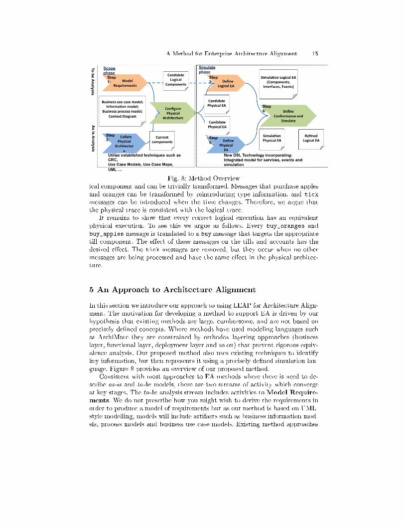
Fig. 8: Method Overviewical component and can be trivially transformed. Messages that purchase applesand oranges can be transformed by reintroducing type information, and tick
messages can be introduced when the time changes. Therefore, we argue thatthe physical trace is consistent with the logical trace.
It remains to show that every correct logical execution has an equivalentphysical execution. To see this we argue as follows. Every buy_oranges andbuy_apples message is translated to a buy message that targets the appropriatetill component. The e�ect of these messages on the tills and accounts has thedesired e�ect. The tick messages are removed, but they occur when no othermessages are being processed and have the same e�ect in the physical architec-ture.
5 An Approach to Architecture Alignment
In this section we introduce our approach to using LEAP for Architecture Align-ment. The motivation for developing a method to support EA is driven by ourhypothesis that existing methods are large, cumbersome, and are not based onprecisely de�ned concepts. Where methods have used modeling languages suchas ArchiMate they are constrained by orthodox layering approaches (businesslayer, functional layer, deployment layer and so on) that prevent rigorous equiv-alence analysis. Our proposed method also uses existing techniques to identifykey information, but then represents it using a precisely de�ned simulation lan-guage. Figure 8 provides an overview of our proposed method.
Consistent with most approaches to EA methods where there is need to de-scribe as-is and to-be models, there are two streams of activity which convergeat key stages. The to-be analysis stream includes activities to Model Require-ments. We do not prescribe how you might wish to derive the requirements inorder to produce a model of requirements but as our method is based on UML-style modelling, models will include artifacts such as business information mod-els, process models and business use case models. Existing method approaches
16 Tony Clark, Balbir S. Barn, and Samia Oussena
such as Catalysis [8] and its derivatives [7] could be used for developing informa-tion models whilst recommended approaches for process modeling could includeOuld's approach [21].
In parallel to the Model Requirements step, the activities in the Col-late Physical Architecture stage will bring together existing descriptions ofsystems and their con�gurations. Our experience of such descriptions are largepictorial based documentation captured using drawing tools such as Powerpoint.A key output of this stage is a description of the systems that exist in the or-ganization. We recommend capturing the description of each system as a UMLComponent to aid the migration to later stages of the method. Again, the methoddoes not prescribe new approaches, it leaves it to the practitioner to determinehow to produce the artifacts required.
The Con�gure Physical Architecture step slices a description of an EAto determine what system components are likely to be impacted by emerging re-quirements. Techniques that can be used to support this impact analysis includesuse case maps [5]. A use case map is simply a trace of path of causal sequencesof events across a set of system components representing an EA. The events aretriggered by a business use case identi�ed in the Model Requirements step.
Alternative approaches that could be used in this step include the use of CRCto help identify those system components that are (collaboratively) responsiblefor delivering a business use case [32]. The key output from this activity is an ar-tifact expressed in system components that includes all the EA system elementsthat will be subject to some impact as a result of the emerging requirements.
Up to now, the steps in the method have utilized well-established notationsand techniques. The subsequent steps in stage 2 incorporate an integrated set ofconcepts from SOA and complex event processing.
The De�ne Logical Enterprise Architecture (L-EA) step produces amodel based description of a target logical EA - that is - the system components,information structures and constraints that are required as a result of the ModelRequirements step. Where appropriate the Logical EA may use candidate logicalcomponents from the Con�gure Physical Architecture step.
The Logical EA (L-EA) uses our integrated concepts derived from SOA andcomplex event modeling so the L-EA is expressed as components o�ering services,raised events, requested services and monitored events. Dependencies betweencomponents are thus expressed in terms of services request and ful�llments andevent management.
TheConformance step uses simulation to produce and visualize results. Thelogical architecture describes what is required and the physical to-be architecturede�nes how existing systems can be used to satisfy the requirements. It remainsto validate the physical architecture by showing that the behavior conforms tothe requirements. If the simulation produces the same output when it is runwith both the logical and physical EA de�nitions then we claim that they arealigned. Such an approach presents a practical solution that is geared toward EApractitioners.
A Method for Enterprise Architecture Alignment 17
6 Case Study
Having outlined the method and technology, this section presents a genuinerequirement faced by IT directors in UK higher education institutions to deliverkey information sets (KIS) to applicants deciding on which course and whichuniversity to chose for study at undergraduate level.
Higher education institutions (HEI) in the UK are faced with a challengingand dynamic business environment where public funding of HEIs has been re-duced by up to 70%. This lost funding is being replaced by the introductionof a new student fees regime beginning in 2012 following a bill introduced inthe UK Parliament in November 2010. The UK Government is of the view thatstudents will require key information in order to make informed decisions re-garding the selection of courses and institutions. Currently this information isnot readily available in a consistent and easily accessible form. Consequently theHigher Education funding body (HEFCE) is coordinating the speci�cation ofthe required information and how it is to be made available and at what time.
HEFCE produces KIS data at a given census date each year. In order to beincluded in KIS, each university must register with both the NSS and DHLEgovernment agencies before the census date. KIS information consists of NSSdata, teaching and learning data from each university, �nancial data from eachuniversity (including university owned and private accommodation costs), em-ployability data from the DHLE agency.
The NSS data is completed by students via a web portal. The details of theinformation go to the NSS agency and the university is informed of the comple-tion for their records. Private property prices within the geographic area aroundthe university are captured by monitoring RSS feeds from property companies.
7 Applying LEAP to the Case Study
Section 4 has shown a detailed, but simple example of using LEAP for architec-ture alignment. The example shows how LEAP is used to capture the top-levelinformation structures and invariants that arise from a business requirement,how LEAP can be used to represent an architecture of interacting componentsbased on existing IT systems, and then how alignment is established throughsimulation and rigorous argument.
Section 5 has outlined a pragmatic approach to Architecture Alignment thatcan be based on a range of technologies. This section follows the method usingLEAP. Since the case study is quite large we will present an overview and includesamples of the implementation where these are illustrative of our approach.
7.1 Step 1: Model Requirements
Figure 9 shows the information model that supports the KIS requirements. Themodel is taken directly from the LEAP tool that represents the requirements as
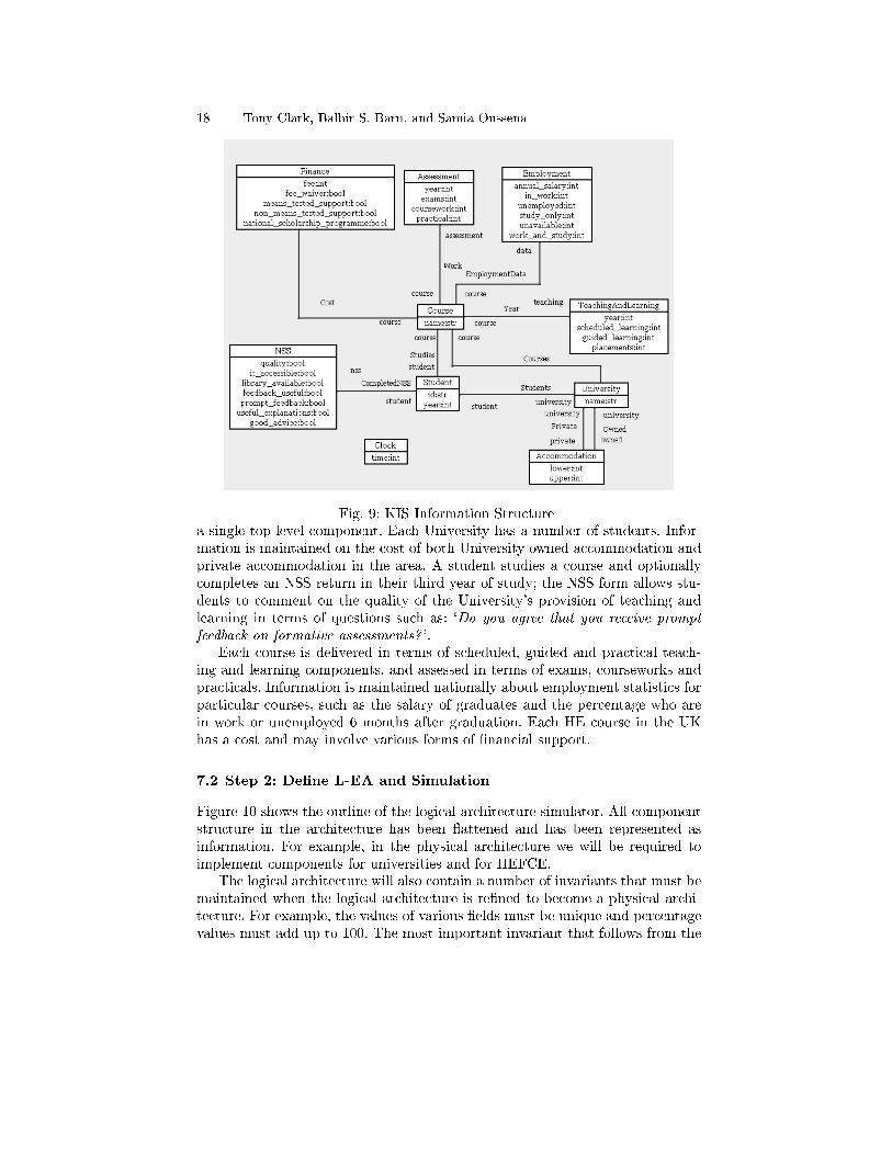
18 Tony Clark, Balbir S. Barn, and Samia Oussena
Fig. 9: KIS Information Structurea single top-level component. Each University has a number of students. Infor-mation is maintained on the cost of both University owned accommodation andprivate accommodation in the area. A student studies a course and optionallycompletes an NSS return in their third year of study; the NSS form allows stu-dents to comment on the quality of the University's provision of teaching andlearning in terms of questions such as: `Do you agree that you receive prompt
feedback on formative assessments? '.Each course is delivered in terms of scheduled, guided and practical teach-
ing and learning components, and assessed in terms of exams, courseworks andpracticals. Information is maintained nationally about employment statistics forparticular courses, such as the salary of graduates and the percentage who arein work or unemployed 6 months after graduation. Each HE course in the UKhas a cost and may involve various forms of �nancial support.
7.2 Step 2: De�ne L-EA and Simulation
Figure 10 shows the outline of the logical architecture simulator. All componentstructure in the architecture has been �attened and has been represented asinformation. For example, in the physical architecture we will be required toimplement components for universities and for HEFCE.
The logical architecture will also contain a number of invariants that must bemaintained when the logical architecture is re�ned to become a physical archi-tecture. For example, the values of various �elds must be unique and percentagevalues must add up to 100. The most important invariant that follows from the

A Method for Enterprise Architecture Alignment 19
component kis_logical {component kis {model { // KIS Information Structure... }
port in[in]:interface {make_university(name:str,courses:void):void;register_student(university:str,student:str,course:str):void;accommodation(university:str,lower:int,upper:int):void;owned(university:str,lower:int,upper:int):void;complete_nss(student:str,quality:bool,it_accessible:bool,library_available:bool,...):void
}operations {make_university(name,courses) {let u = new University(name)in for Course(course_name,t1,t2,t3,a1,a2,a3,employment,finance) in courses {let c = new Course(course_name)in // create and link instances of the information model...
}}register_student(university,student,course) {�nd u=University(university) in state {�nd Courses(u,Course(course)) in state {let s = new Student(student)in new Students(u,s), new Studies(s,Course(course))
} else error('no course ' + course)} else error('no university ' + university)
}complete_nss(student,q,i,l,f,p,u,g) { ... }accommodation(university,lower,upper) { ... }owned(university,lower,upper) { ... }
}}state {Time(0)Message(0,kis.in,'make_university',['middle england',[Course('Computer Science', TeachingAndLearning(1,60,40,0),..., Assessment(1,100,0,0),...,Employment(20000,50,20,20,10,0), Finance(9000,true,true,true,true))
]])Message(1,kis.in,'register_student',['middle england','fred','Computer Science'])...Message(2,kis.in,'complete_nss',['fred',true,true,true,true,true,true,true])Message(3,kis.in,'accommodation',['middle england',500,1000])Message(4,kis.in,'owned',['middle england',500,1000])...End(100)
}rules {send: Time(t) Message(t,p,m,args) { send(p,m,args); delete Message(t,p,m,args) }tick: Time(t) not(Message(t,_,_,_)) not(End(t)) { replace Time(t) with Time(t+1) }
}}
Fig. 10: Logical Architecture Simulationbusiness requirement is that when the time reaches a speci�c point, all the in-formation necessary to construct the KIS report must be available. Given thisrequirement, any mapping from logical to physical must provide KIS data nomatter how distributed the data becomes.
7.3 Step 3: Collate Physical-EA
The next step of our method involves reviewing the current physical as-is systemarchitecture. Most organizations have a systems overview which is used as the

20 Tony Clark, Balbir S. Barn, and Samia Oussena
input to this step. The result is an understanding of the current capability ofthe organization in terms of systems, interfaces, information and events.
The context for the physical EA includes external systems. When generatingKIS data, all universities must work with the following external systems: studentsuse the web to complete NSS reports; employability information is maintainedby the dhle; the NSS forms are collated by nss; an RSS property feed providesinformation on the cost of accommodation at regular intervals; hefce managesthe KIS process.
We will use the University of Middlesex (Mdx), London, UK as the basisfor our case study. Space limitations prevent us from providing a complete de-scription of the Mdx physical architecture, however it is consistent with mostUK HEIs and includes systems for registry, an asset management system thatincludes a sub-system for university accommodation, an examinations database,a library system, a �nancial management system called PAFIS, a teaching andlearning system called OASIS, an alumni management system, a student portal,and a sta� portal.
7.4 Step 4: Con�gure Physical-EA
The next step of the method analyses the physical system of an organization andtakes an appropriate slice to produce just those systems that will be involvedin the required to-be architecture. In the case of supplying KIS data, we knowthat Mdx will need to provide student, accommodation, teaching and learning,assessment and �nancial information. Therefore, the P-EA will not include thealumni or library management systems.
7.5 Step 5: De�ne Physical-EA
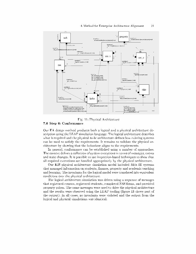
Figure 11 shows a physical architecture model for KIS including two uni-versities. The physical architecture distributes the information structures andinvariants across multiple components and uses component-nesting within theuniversity components to drill down to particular IT systems. For the purposesof simulation, the multiple universities are constructed using template patterns.
The simulation is driven by the hefce component that triggers an event whenit is time to construct the KIS reports. The simulation uses pattern matchingacross multiple events within hefce to determine when all of the information hasbeen received as shown in �gure 12. Of particular interest are the rules de�nedby hefce. When both registration events are received in any order from NSSand DHLE then hefce registers the university. The kis_run rule detects whenit is time for KIS reporting and sends messages to all universities, to DHLE andto NSS. The replies from these messages are received in an arbitrary order andupdate the hefce database; the kis rule detects when updates have occurred(again in any order) and creates the KIS report for each university.
A Method for Enterprise Architecture Alignment 21
Fig. 11: Physical Architecture7.6 Step 6: Conformance
Our EA design method produces both a logical and a physical architecture de-scription using the LEAP simulation language. The logical architecture describeswhat is required and the physical to-be architecture de�nes how existing systemscan be used to satisfy the requirements. It remains to validate the physical ar-chitecture by showing that the behaviour aligns to the requirements.
In general, conformance can be established using a number of approaches.The context de�nes a collection of system executions in terms of messages, eventsand state changes. It is possible to use inspection-based techniques to show thatall required executions are handled appropriately by the physical architecture.
Our KIS physical architecture simulation model included Mdx IT systemsthat managed information on students, �nance, property and academic teachingand learning. The invariants for the logical model were translated into equivalentconditions over the physical architecture.
The logical architecture simulation was driven using a sequence of messagesthat registered courses, registered students, completed NSS forms, and providedproperty prices. The same messages were used to drive the physical architectureand the results were observed using the LEAP tooling (�gure 13 shows part ofthe output). In all cases, no invariants were violated and the output from thelogical and physical simulations was identical.

22 Tony Clark, Balbir S. Barn, and Samia Oussena
component hefce {state { KIS_Census(5) }port uni_bcast[out]: interface {
get_finances():void;get_students():void;get_teaching():void;get_accommodation():void
}port in[in]:interface {finances(uni:str,data:void):void;students(uni:str,data:void):void;scores(data:void):void;employment(data:void):void;teaching(uni:str,data:void):void;accommodation(uni:str,data:void):void
}port nss_out[out]: interface { get_scores():void }port dhle_out[out]: interface { get_employment():void }operations { // updates to database corresponding to input messages ... }
rules {university: NSS_Registered(name) DHLE_Registered(name) { new University(name) }kis_run: Time(n) KIS_Census(n) {uni_bcast <- get_finances();uni_bcast <- get_students();uni_bcast <- get_teaching();uni_bcast <- get_accommodation();dhle_out <- get_employment();nss_out <- get_scores()
}kis: University(name)
Students(name,studies)Finance(name,finance)Teaching(name,tdata)Accommodation(name,adata)NSS(data)Employment(edata) {
let filtered_nss = [ nss_data | NSS(student_name,nss_data) <- data,Studies(Student(student_name),_) <- studies ];
filtered_employment = [ Employment(c,d) | Employment(name,c,d) <- edata ]in // construct report
}}
Fig. 12: The HEFCE SimulationFinally, if we require total con�dence in conformance then we need to resort
to formal methods such as model checking and theory proving. For large sys-tems such as those found in EA, formal methods are often impractical in termsof complexity. That said, a formal semantics for LEAP is an area for futuredevelopment in order to investigate whether formal methods could help.
8 Analysis and Conclusion
Enterprise Architecture remains a confusing and constantly evolving collectionof methods and frameworks which are generally characterized by an expansiveoutlook, lack of precision, a focus on diagrams and an emphasis on documentmanagement. The result is that existing approaches are di�cult to analyze andprocess. This paper has presented an e�ort to reduce the scope of EA in orderto pin down the core use cases of managing change and better understanding

A Method for Enterprise Architecture Alignment 23
Fig. 13: Part of the KIS Simulation Outputthe impact of changing requirements on existing technical architectures of anorganization.
Fig. 14: Leap Tool
24 Tony Clark, Balbir S. Barn, and Samia Oussena
We have proposed a synthetic language for EA called LEAP and contrastedit with a leading analytic language called ArchiMate. Our claim is that the largecollection of EA features in ArchiMate are not orthogonal and can be mapped toa much smaller collection in LEAP. This claim is validated through a real-worldcase study although it remains to compare the resulting LEAP simulation withthe equivalent ArchiMate models. Furthermore, we do not claim that syntheticlanguages such as ArchiMate are redundant since they are domain-speci�c andpresent features in terms recognizable to a business analyst; however, LEAPcould be used as a basis for EA language precision through mappings such asthat described in �gure 1.
Our claim goes further by proposing that EA languages should be executablewherever that makes sense. EA aims to address features of organizations; organi-zations are systems that operate in terms of structure, resources and information.LEAP provides a simple and universal basis for representing these EA charac-teristic features without introducing unnecessary distinctions between otherwisefundamentally identical concepts. This claim has been validated by applyingLEAP to a real-world EA case study in order to address a typical EA use-case:Architecture-Alignment. We have shown that an operational semantics can beused in a practical sense to build con�dence that two di�erent architecturaldescriptions of the same system are equivalent.
We claim that LEAP represents a contribution to industrial EA because ittakes a pragmatic approach to introducing precision in EA. Current EA lan-guages lie at the sketching end of the development life-cycle. This is valuable,but is not amenable to automated analysis. At the other end of the spectrumlies formal methods and their associated tools, however it is not clear that thereis any evidence that such a formalized approach to EA would be tractable giventhe size and complexity of the systems involved. LEAP lies in-between on thisspectrum by supporting diagrams for the key features of an architecture, a high-level programming language for the details and a semantics that, in principle,does not rule out formal analysis in the future.
How would Industry use LEAP? Our experience with KIS and other casestudies we have developed, is that the ability to create a simulation of part ofan organization is very valuable. LEAP does not require components to mapon to physical resources and organizational units, it is intended that features ofan EA application, whether tangible or intangible, can be expressed in terms ofcomponents, data, rules, operations, constraints, state-machines, and messages.A novel feature of LEAP is that both components and operations are higher-order which means that it is easy to capture template patterns, as shown in thecase of the tills in the greengrocer example and the universities in the KIS casestudy. In another example not reported here, we have used template patterns tocapture the life-cycle of a customer record as a component.
Therefore, Industry can use LEAP to produce simulations of architectures atany level of abstraction, and the operational nature of LEAP makes it practicalto compare the same system developed to di�erent levels of detail. Since theinformation is represented as LEAP models, it is possible to generate artifactsfrom them, including code, although this is something to be investigated as future
A Method for Enterprise Architecture Alignment 25
work. In addition, since components are encapsulated, our intention is to allowLEAP to interface to existing systems, thereby providing a means to migrate anexisting architecture by simulating the new components and gradually replacingthem with new IT systems.
Our use of LEAP for the KIS analysis at Mdx has shown that existing Uni-versity information systems can support the new HEFCE regulations subject tobeing able to provide the appropriate interfaces and supporting the informationmodels de�ned in the simulation. Given a simulation, the mapping from LEAPto real information systems is straightforward. LEAP tooling supports singlestepping through the simulation together with snapshots of the simulation stateas shown in �gure 14.
LEAP does not claim to be a universal technology for EA, however, as de-scribed above, we have taken a fundamentally di�erent approach to the design ofa language for EA compared to that provided by current systems. Since LEAPis a synthetic language it is necessarily limited, however it provides a basis onwhich to test the hypothesis that the our proposed concepts are su�cient for awide variety of EA use-cases and, where it is found lacking, our claim is thatthe required extensions will be orthogonal and precisely de�ned where possible.Current limitations include the ability to express and manage the re�nement ofbusiness goals and to express non-functional system requirements (such as costand risk). We have started a process of consultation with Industry in order tounderstand how these features need to be represented and processed.
References
1. A. Arsanjani, S. Ghosh, A. Allam, T. Abdollah, S. Ganapathy, and K. Holley.Soma: A method for developing service-oriented solutions. IBM systems Journal,47(3):377�396, 2008.
2. M. Assmann and G. Engels. Transition to service-oriented enterprise architecture.Software Architecture, pages 346�349, 2008.
3. B. Biggs. Ministry of defence architectural framework (modaf). In IEE SeminarDigests, volume 43, 2005.
4. T. Bucher, R. Fischer, S. Kurpjuweit, and R. Winter. Analysis and applicationscenarios of enterprise architecture: An exploratory study. In 10th IEEE Inter-national Enterprise Distributed Object Computing Conference Workshops, 2006.EDOCW'06, 2006.
5. R.J.A. Buhr and R.S.O. Casselman. Use case maps for object-oriented systems,volume 302. Prentice Hall, 1996.
6. Y.E. Chan and B.H. Reich. IT alignment: what have we learned? Journal ofInformation Technology, 22(4):297�315, 2007.
7. J. Cheesman and J. Daniels. UML components. Addison-Wesley, 2001.8. Desmond F. D'Souza and Alan Cameron Wills. Objects, components, and frame-
works with UML: the catalysis approach. Addison-Wesley Longman Publishing Co.,Inc., Boston, MA, USA, 1999.
9. M. Ekstedt, P. Johnson, A. Lindstrom, M. Gammelgard, E. Johansson, L. Plazaola,E. Silva, and J. Lilieskold. Consistent enterprise software system architecture forthe cio - a utility-cost based approach. In System Sciences, 2004. Proceedings ofthe 37th Annual Hawaii International Conference on System Sciences (HICSS'04),2004.

26 Tony Clark, Balbir S. Barn, and Samia Oussena
10. U. Frank. Multi-perspective enterprise modeling (memo) conceptual frameworkand modeling languages. In System Sciences, 2002. HICSS. Proceedings of the35th Annual Hawaii International Conference on, pages 1258�1267. IEEE, 2002.
11. F.G. Goethals, M. Snoeck, W. Lemahieu, and J. Vandenbulcke. Management andenterprise architecture click: The fad (e) e framework. Information Systems Fron-tiers, 8(2):67�79, 2006.
12. The Open Group. Archimate technical standard, 2008.http://www.opengroup.org/archimate/.
13. J.C. Henderson and N. Venkatraman. Strategic alignment: Leveraging informationtechnology for transforming organizations. IBM systems Journal, 32(1), 1993.
14. C. Huemer, P. Liegl, T. Motal, R. Schuster, and M. Zapletal. The developmentprocess of the un/cefact modeling methodology. In Proceedings of the 10th inter-national conference on Electronic commerce, page 36. ACM, 2008.
15. ITU. Basic reference model of open distributed processing - part 1: Overview andguide to use. In ITU Recommendation X.901 | ISO/IEC 10746-1. ISO/ITU, 1994.
16. P. Johnson, E. Johansson, T. Sommestad, and J. Ullberg. A tool for enterprisearchitecture analysis. In Enterprise Distributed Object Computing Conference,2007. EDOC 2007. 11th IEEE International, pages 142�142. IEEE, 2007.
17. P. Johnson, R. Lagerström, P. Närman, and M. Simonsson. Enterprise architectureanalysis with extended in�uence diagrams. Information Systems Frontiers, 9(2),2007.
18. Marc Lankhorst. Introduction to enterprise architecture. In Enterprise Architectureat Work, The Enterprise Engineering Series. Springer Berlin Heidelberg, 2009.
19. B.M. Michelson. Event-driven architecture overview. Patricia Seybold Group, 2006.20. K.D. Niemann. From enterprise architecture to IT governance: elements of e�ective
IT management. Vieweg+ Teubner Verlag, 2006.21. M.A. Ould. Business Process Management: a rigorous approach. British Informat-
ics Society Ltd, 2005.22. S. Overbeek, B. Klievink, and M. Janssen. A �exible, event-driven, service-oriented
architecture for orchestrating service delivery. IEEE Intelligent Systems, 24(5):31�41, 2009.
23. C.M. Pereira and P. Sousa. A method to de�ne an enterprise architecture usingthe zachman framework. In Proceedings of the 2004 ACM symposium on Appliedcomputing, pages 1366�1371. ACM, 2004.
24. K. Raymond. Reference model of open distributed processing (rm-odp): Introduc-tion. In IFIP TC6 International Conference on Open Distributed Processing, pages3�14. Brisbane, Australia, Chapman and Hall, 1995.
25. C. Riege and S. Aier. A Contingency Approach to Enterprise Architecture MethodEngineering. In Service-Oriented Computing�ICSOC 2008 Workshops. Springer,2009.
26. G. Sharon and O. Etzion. Event-processing network model and implementation.IBM Systems Journal, 47(2):321�334, 2008.
27. J. Spencer et al. TOGAF Enterprise Edition Version 8.1. 2004.28. M.W.A. Steen, P. Strating, M.M. Lankhorst, H. ter Doest, and M.E. Iacob. Service-
oriented enterprise architecture. Stojanovic, Z.; Dahanayake, A.), Service OrientedSystems Engineering, Hershey, pages 132�154, 2005.
29. A. Tang, J. Han, and P. Chen. A comparative analysis of architecture frame-works. In Software Engineering Conference, 2004. 11th Asia-Paci�c, pages 640�647. IEEE, 2004.
30. A. Wegmann, P. Balabko, L.S. Lê, G. Regev, and I. Rychkova. A method and toolfor business-it alignment in enterprise architecture. In CAiSE05 Forum. Citeseer,2005.
31. A. Wegmann, G. Regev, I. Rychkova, L.S. Lê, J.D. De La Cruz, and P. Julia.Business and it alignment with seam for enterprise architecture. In EnterpriseDistributed Object Computing Conference, 2007. EDOC 2007. 11th IEEE Interna-tional, pages 111�111. IEEE, 2007.

A Method for Enterprise Architecture Alignment 27
32. R. Wirfs-Brock, B. Wilkerson, and L. Wiener. Designing object-oriented software,volume 13. Prentice Hall Englewood Cli�s, New Jersey, 1990.
33. DE Wisnosky and J. Vogel. DoDAF Wizdom: A Practical Guide to Planning,Managing and Executing Projects to Build Enterprise Architectures Using theDepartment of Defense Architecture Framework (DoDAF), 2004.
34. J.A. Zachman. A framework for information systems architecture. IBM systemsjournal, 38(2/3), 1999.