a massively parallel finite-element eigensolver for ... › ... › 15750 › slac-pub-15976.pdfa...
TRANSCRIPT
1
A Massively Parallel Finite-Element Eigensolver for Mechanical Modal Analysis of Accelerator Cavities
O. Kononenko, L. Ge, K. Ko, Z. Li, C.-K. Ng and L. Xiao
SLAC National Accelerator Laboratory
2575 Sand Hill Road, Menlo Park, CA 94025, USA E-mail: [email protected]
Abstract ACE3P, a 3D massively parallel finite-element simulation suite that can perform integrated electromagnetic, thermal and mechanical analysis, is being developed at SLAC National Accelerator Laboratory for the past decades becoming an important tool for design and analysis of particle accelerators. Based on the finite-element framework of ACE3P, a new eigensolver is developed for modal analysis of mechanical structures. Running on massively parallel computer platforms, the new solver can handle large-scale problems by utilizing their computing resources and thus provides time-efficient capability to perform modal analysis of complicated accelerator components. This simulation functionality helps understanding the microwave response and feedback requirements of superconducting cavities to microphonics that can affect the operational reliability of a particle accelerator. Keywords: Particle accelerators, parallel computing, eigenvalue problem, structural mechanics
1. Introduction
In a wide range of scientific and engineering applications [1-3], many mechanical structures are subject to external loading. This loading is often a source of vibrations that, unless carefully controlled, could pose serious problems to a structure leading to performance degradation or even damage. In order to mitigate this adverse effect, it is essential to determine the structure’s eigenmodes and perform appropriate modal analysis [4].
In the area of particle accelerators, the use of superconducting cavities to accelerate charged particle beams has become more common. A superconducting cavity [1] normally has a high quality factor Q (at the order of 109) resulting in a narrow frequency bandwidth accelerating structure with higher sensitivity to microphonics coming from the low frequency oscillations of the environment in the cryostat. Accurate design of the cavity, involving modal analysis, can help reducing the microphonics effect to a tolerable level and, hence, gain in efficiency saving the driving power and machine operation costs. A necessary step to perform this study is an accurate calculation of the eigen frequencies and eigenmodes of the accelerating structure.
Most eigenvalue solvers in structural mechanics are based on the finite-element method [5] that is applicable to study arbitrary complex geometries and provides required accuracy for the calculation. Commercial software to perform modal analysis also exists, but the development has been mainly targeted on desktop computer hardware although parallel implementations are available as well. For problems of large sizes, it is advantageous and required to use parallel computation for large memory usage and computational time speedup.
ACE3P simulation suite [6] is being developed for large-scale accelerator applications using high performance computing at SLAC National Accelerator Laboratory for the past decades and has
SLAC-PUB-15976
Work supported by US Department of Energy under contract DE-AC02-76SF00515 and SciDAC.

2
been used extensively in the design and optimization studies for many accelerator projects [7-9]. As a part of ACE3P, mechanical eigensolver we developed uses the existing software infrastructure, which includes mesh domain decomposition, matrix assembly scheme and implementations of linear and eigen solvers.
The paper is organized as follows. In the next section, a mathematical model for the eigenvalue problem for the linear elasticity equations is developed using the finite element method Based on the model, a new eigensolver to determine mechanical natural frequencies and mode shapes is implemented as a part of the ACE3P simulation suite and described in Section 3. In Section 4, a benchmark of the mechanical eigensolver against analytical model and other simulation software is presented. In Section 5, an application of the mechanical eigensolver to realistic accelerator structure is demonstrated and a parallel performance on supercomputers is discussed. Finally, a short summary is given in Section 6.
2. Mathematical Model 2.1 Eigenvalue problem
In a direct tensor form the governing equations of the linear elasticity are the equation of
motion (second Newton’s law), the strain-displacement equation and the Hook’s law [10]: ∇•σ +F = ρu (1)
ε =12∇u+∇uT( ) (2)
σ =Cε (3)
where σ and ε are the stress and strain tensors, u is the displacement vector, F is the vector of the external force, C — the stiffness tensor and ρ is the material density, respectively. These equations hold true in a 3D domain Ω under the linearization assumptions: infinitesimal strains and linear relationships between the components of the stress and strain.
A well-posed problem must also include additional constrains on the domain boundary ∂Ω [10]. In this paper we consider Dirichlet, i.e. prescribed displacement (4), and Neumann, i.e. prescribed normal loading (5), boundary conditions:
u = u0 (4) σ •n = t (5)
where u0 is the vector of prescribed displacements, n — the outer normal and t is the traction vector, respectively. Defining a boundary ∂Ω as Γ, we assume that Γ = ΓD∪ΓN , where (4) holds true on ΓD and (5) on ΓN, see Fig. 1.

3
Figure 1. Domain Ω, where (1-3) are considered and a boundary Γ where either Dirichlet or Neumann boundary conditions hold true.
We assume that Ω consists of an isotropic material, so that the Hook’s law (3) can be explicitly written as:
𝜎!!𝜎!!𝜎!!𝜎!"𝜎!"𝜎!"
=
2𝜇 + 𝜆 𝜆 𝜆 0 0 0𝜆 2𝜇 + 𝜆 𝜆 0 0 0𝜆 𝜆 2𝜇 + 𝜆 0 0 00 0 0 𝜇 0 00 0 0 0 𝜇 00 0 0 0 0 𝜇
𝜀!!𝜀!!𝜀!!𝜀!"𝜀!"𝜀!"
(6)
where λ and µ are Lamé coefficients [10]. These material properties can also be expressed in terms of the Poisson ratio 𝜐 and the Young modulus 𝐸 as
𝜆 = 𝐸𝜐
1+ 𝜐 (1− 2𝜐)
𝜇 = 𝐸
2 1+ 𝜐
Plugging (2) into (6) we get:
σ = 2µε +λtr(ε)I = 2µ 12(∇u+∇uT )+λ(∇•u)I (7)
To formulate an eigenvalue problem, we also assume that there are no external forces
involved and oscillations are harmonically dependent on time: F = 0u =Ueiϖ t
where ω = 2πf is the angular frequency, f is the frequency, t — the time and U is the displacement magnitude, respectively.
Plugging these assumptions into (1) we obtain a governing equation in Ω:
∇•σ = −ω 2ρu (8)
To study the eigenvalue problem, homogenous boundary conditions (4-5) are considered:

4
u = 0 (9)
σ •n = 0 (10)
The constraints (9-10) correspond to the fixed displacement on ΓD and free boundary condition on ΓN respectively.
Equation (8) considered along with (7) and boundary conditions (9-10) is an eigenvalue problem for the linear elasticity equations under the given assumptions. Determining eigenmodes, we are interested in eigen frequencies such that the solutions of (7-10) have non-zero displacements u.
2.2 Weak Formulation and Finite-Element Method
Multiplying (8) by a test vector function 𝑣:ℝ! → ℝ! and integrating it over the domain Ω results in:
∇•σ( )Ω
∫ •vdΩ = −ω 2 ρΩ
∫ (u•v)dΩ
(11)
Using divergence theorem [11]:
∇•σ( )Ω
∫ •vdΩ = vΓ
∫ (σ •n)dΓ− σΩ
∫ •∇vdΩ
we substitute this relation into (11) and obtain:
vΓ
∫ (σ •n)dΓ− σΩ
∫ •∇vdΩ = −ω 2 ρΩ
∫ (u•v)dΩ
Applying the boundary conditions (9-10) on Γ = ΓD∪ΓN , the first integral vanishes as
σ •n ΓN= 0 and σ = 2µ 1
2(∇u+∇uT )+λ(∇•u)I ΓD
= 0 . Taking into account (7), we finally derive a
weak form of the governing equation for the displacement vector u:
(2µ 12(∇u+∇uT )+λ(∇•u)I
Ω
∫ )•∇vdΩ =ω 2 ρΩ
∫ (u•v)dΩ
(12)
The weak form (12) is also applicable to inhomogeneous materials, i.e. when the Lamé coefficients λ and µ as well as the material density ρ are space-dependent.
Using a standard procedure in finite-elements method [5], we use nodal basis functions 𝜑!:ℝ → ℝ [12] and express the 3D displacement field as
u = ( !u , !v , !w ) = uiφi, viφi, wiφii=1
N
∑i=1
N
∑i=1
N
∑#
$%
&
'(
where N is the number of nodes in the mesh discretization of Ω, 𝑢! , 𝑣! and 𝑤! are the displacement components at the i-th node of the mesh.

5
Taking 𝑣 = (𝜑! , 0, 0), 𝑣 = (0,𝜑! , 0) and 𝑣 = (0, 0,𝜑!) we reduce (12) to a linear algebraic system with unknown displacements and angular frequency:
Ku =ω 2Mu (13)
where K and M are the stiffness and mass matrices respectively. The explicit forms of the matrices can be written as
𝐾!" =𝐾!! 𝐾!" 𝐾!"𝐾!" 𝐾!! 𝐾!"𝐾!" 𝐾!" 𝐾!! !"
𝑀!" =𝑀!! 0 00 𝑀!! 00 0 𝑀!! !"
(14)
where 𝑖, 𝑗 = 1,𝑁 and
𝐾!! = 2𝜇 + 𝜆𝜕𝜑!𝜕𝑥
𝜕𝜑!𝜕𝑥 + 𝜇
𝜕𝜑!𝜕𝑦
𝜕𝜑!𝜕𝑦 + 𝜇
𝜕𝜑!𝜕𝑧
𝜕𝜑!𝜕𝑧 𝑑𝛺
!
𝐾!" = 𝜇𝜕𝜑!𝜕𝑦
𝜕𝜑!𝜕𝑥 + 𝜆
𝜕𝜑!𝜕𝑥
𝜕𝜑!𝜕𝑦 𝑑𝛺
!
𝐾!" = 𝜇𝜕𝜑!𝜕𝑧
𝜕𝜑!𝜕𝑥 + 𝜆
𝜕𝜑!𝜕𝑥
𝜕𝜑!𝜕𝑧 𝑑𝛺
!
𝐾!! = 𝜇𝜕𝜑!𝜕𝑥
𝜕𝜑!𝜕𝑥 + 2𝜇 + 𝜆
𝜕𝜑!𝜕𝑦
𝜕𝜑!𝜕𝑦 + 𝜇
𝜕𝜑!𝜕𝑧
𝜕𝜑!𝜕𝑧 𝑑𝛺
!
𝐾!" = 𝜇𝜕𝜑!𝜕𝑧
𝜕𝜑!𝜕𝑦 + 𝜆
𝜕𝜑!𝜕𝑦
𝜕𝜑!𝜕𝑧 𝑑𝛺
!
𝐾!! = 𝜇𝜕𝜑!𝜕𝑥
𝜕𝜑!𝜕𝑥 + 𝜇
𝜕𝜑!𝜕𝑦
𝜕𝜑!𝜕𝑦 + 2𝜇 + 𝜆
𝜕𝜑!𝜕𝑧
𝜕𝜑!𝜕𝑧 𝑑𝛺
!
𝑀!! = 𝜌𝜑!𝜑!𝑑𝛺
!
The boundary conditions (9-10) are imposed in the following way: – Dirichlet, the node is fixed in all three directions: 𝑢! = 𝑣! = 𝑤! = 0 – Neumann, the node is free to move in all three directions, i.e. 𝑢! , 𝑣! and 𝑤! are degrees of
freedom – Mixed, the node is fixed in some directions and free in other directions, i.e. a component-
wise Dirichlet or Neumann boundary condition
It should be mentioned that imposing the boundary conditions, both the stiffness and mass matrices in (13) are real and symmetric. In addition, M is positive definite, and therefore appropriate numerical methods have to be applied to solve the discretized system.

6
3. Software Design and Parallelization
Based on the developed mathematical model described in the previous section, a mechanical eigensolver is implemented within the framework of the ACE3P simulation suite [6]. This solver adds a new modelling capability in ACE3P’s multi-physics module TEM3P [13], which is designed for integrated electromagnetic, thermal and mechanical analysis of accelerator structures.
The simulation workflow of ACE3P is divided into three main steps, namely, preprocessing, executing ACE3P module, and post-processing. While the preprocessing and postprocessing are performed on local desktops, ACE3P execution is carried out remotely by utilizing the computing resources of the supercomputers at NERSC, the National Energy Research Scientific Computing Center [14].
For preprocessing, we use a third-party software Cubit [15], geometry and mesh generation toolkit developed by Sandia National Laboratories, to build a model or import an existing one and to generate a corresponding mesh. In particular, Cubit is capable of generating unstructured curved tetrahedral 3D meshes, which are converted to NetCDF [16] format as input to ACE3P solvers. Further, the computational mesh is decomposed into NP (number of MPI processes) subdomains using ParMetis [17] or Zoltan [18] libraries.
Figure 2. A typical workflow including ACE3P main modules and a developed modal solver in TEM3P.
The stiffness and mass matrices are assembled in parallel according to the patterns (14) for the
mechanical eigenproblem with appropriate boundary conditions imposed. 3D Gaussian quadratures are used to calculate matrix elements. The resulting matrices are sparse with the patterns similar to the ones involved in the ACE3P’s Omega3P module [19], a finite-element eigenvalue solver for

7
electromagnetic fields. Moreover, the stiffness and mass matrices are real, exactly as in the case of imposing perfect electric boundaries in Omega3P. Therefore, the direct and iterative solvers implemented in Omega3P can be readily adapted to solve (13).
For postprocessing, the displacements for the determined mechanical eigenmodes are visualized using Paraview [20], which is a data analysis and visualization tool with a dedicated SLAC toolbar tailored for ACE3P simulation results [21]. Stresses, strains and deformed meshes are also computed from the displacements and the original computational mesh.
The summarized information about the ACE3P’s main modules and a typical simulation workflow is presented in details on Fig. 2.
4. Convergence and Validation
To validate the proposed method, we consider an eigenvalue problem (1-3) in the hexahedral
domain Ω = [0, Lx] x [0, Ly] x [0, Lz] with the following boundary conditions:
𝑢 = 𝜎!" = 𝜎!" = 0, 𝑥 ∈ {0, 𝐿!} (15) 𝑣 = 𝜎!" = 𝜎!" = 0, 𝑦 ∈ {0, 𝐿!} (16) 𝑤 = 𝜎!" = 𝜎!" = 0, 𝑧 ∈ {0, 𝐿!} (17)
These conditions physically correspond to the greased wall boundary and are treated as the
Mixed ones in this paper. In other words, condition (15) corresponds to (Dirichlet, Neumann, Neumann), (16) to (Neumann, Dirichlet, Neumann) and (17) to (Neumann, Neumann, Dirichlet) component-wise.
According to [22], the eigenvalue problem (1-3) with the boundary conditions (15-17) can be solved analytically and has two sets of eigenvalues:
𝜉!"#! = 1− 2𝜐 𝛼!! + 𝛽!! + 𝛾!!
𝜉!"#(!) = 2 1− 𝜐 𝛼!! + 𝛽!! + 𝛾!! , 𝑙! +𝑚! + 𝑛! > 0
where
𝛼! =𝑙𝜋𝐿!, 𝛽! =
𝑚𝜋𝐿!
, 𝛾! =𝑛𝜋𝐿!, 𝑙,𝑚,𝑛 ∈ ℤ
The multiplicity of 𝜉!"#
(!) is determined by 𝑠𝑖𝑔𝑛 𝑙 + 𝑠𝑖𝑔𝑛 𝑚 + 𝑠𝑖𝑔𝑛 𝑛 − 1, i.e. number of nonzero indexes minus 1. The eigen angular frequency 𝜔 is expressed in terms of 𝜉 as:
𝜔 =𝜉𝐸
2𝜌(1+ 𝜐)(1− 2𝜐)
Based on the analytical model, the eigen frequencies are calculated as the reference values to
be compared with ACE3P simulations. In the following validation study, we assume that Lx = 1 m, Ly = 2 m, Lz = 3 m and the cuboid Ω is made of structural steel. See Table 1 for the exact material properties.

8
Property Value Density, ρ [kg/m3] 7850 Poisson Ratio, υ 0.3 Young’s Modulus, E [GPa] 200
Table 1. Structural steel properties used in the validation.
First, we perform a mesh convergence study of the proposed method with respect to the analytical solution. We start from a mesh with 7K tetrahedral elements and then increase the size regularly to 270K, roughly doubling the mesh size at each step. We use second order basis functions and calculate the first five eigenmodes. The relative frequency error
𝜀 =|𝑓!"#!! − 𝑓!"#"!"$%"|
𝑓!"#"!"$%"
between ACE3P and analytical values is illustrated in Fig. 3 for each mode separately.
Figure 3. Convergence of the proposed method as the relative frequency error against the mesh size.
In Table 2 we compare the eigen frequencies as calculated by ACE3P with those computed
analytically and by the commercial package ANSYS [23].
9
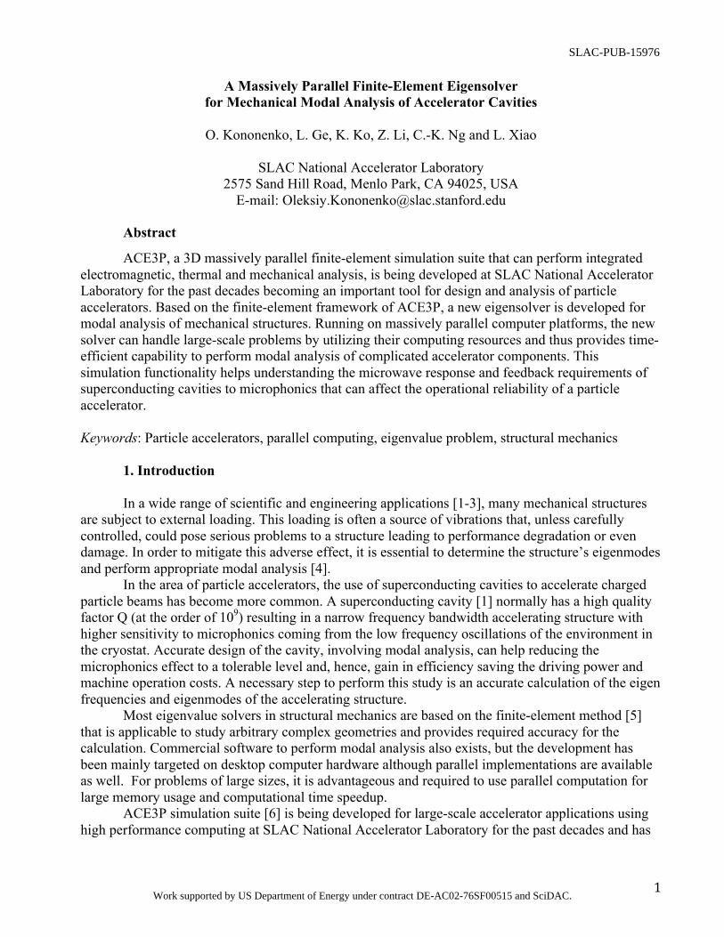
Mode ACE3P Analytics ANSYS
1 940.55 940.55 940.56 2 976.06 976.06 976.06 3 1304.31 1304.31 1304.32 4 1464.09 1464.09 1464.09 5 1649.84 1649.84 1649.84
Table 2. Eigen frequencies [Hz] of the first five modes for the cuboid domain with the greased wall
boundary as calculated by ACE3P, analytically and by ANSYS. The meshes for ACE3P and ANSYS calculations have about 270K tetrahedrons.
In Fig. 4 the corresponding displacement magnitudes calculated using ACE3P and ANSYS are compared for the Mode 1 at 940.55 Hz.
Figure 4. Displacement magnitudes for the Mode 1 at 940.55 Hz as calculated using ACE3P / visualized in Paraview (left) and in ANSYS (right) for 270K tetrahedral meshes (shown in black).
In this validation example, the mechanical eigensolver in ACE3P has been shown to achieve
fast convergence and the calculated eigenmodes frequencies are in a good agreement with those obtained analytically and using ANSYS. The corresponding displacement fields from ACE3P and ANSYS calculations agree well and, due to the same mass-matrix normalization of solution used in the two sets of software, their maximum values are identical, as shown in Fig. 4. 5. Numerical Example of a Large-Scale Simulation
To illustrate the capability to handle realistic problems, we consider the TESLA superconducting accelerating cavity situated in a helium tank [24], see Fig. 5 for details and Table 3 for the corresponding material properties. The liquid helium is not included in the simulation and instead of a microwave tuner attached to the cavity wall, a simplified model with comparable stiffness is considered. We model a half of the radially symmetric structure and prevent any deformations perpendicular to the symmetry plane. In this case all the frequencies obtained will have a multiplicity of two.

10
Figure 5. TESLA superconducting cavity in a tank; the total structure length is 1.28 m
Property Nb Nb-Ti Ti SS Density, ρ [kg/m3] 8700 5700 4540 8000 Poisson Ratio, υ 0.38 0.33 0.37 0.29 Young’s Modulus, E [GPa] 118 68 117 193
Table 3. Mechanical properties of the materials used in the simulation of the TESLA cavity.
The contacts between different parts of the model are assumed to have no separation and no
slip, i.e. bonded contacts, and, building a corresponding mesh in Cubit, tetrahedral elements do not cross the interface between the materials. To properly describe the cavity shape, curvilinear tetrahedral elements are used.
Simulation Parameter ACE3P ANSYS Number of Cores 240 2 Mesh Size 1.2 M 280 K Number of Degrees of Freedom 5.7 M 1.5 M Mesh Type Tet10 Tet4 Solver Time [s] 37 3425
Table 4. Comparison of simulation profiles for ACE3P and ANSYS.
The ACE3P simulation is performed on Edison, NERSC Cray XC30 supercomputer [14], and
the results are crosschecked with the ANSYS modal solver running on a conventional desktop computer, see the simulation profiles in Table 4. The frequencies of the first five eigenmodes are presented in the Table 5.
11
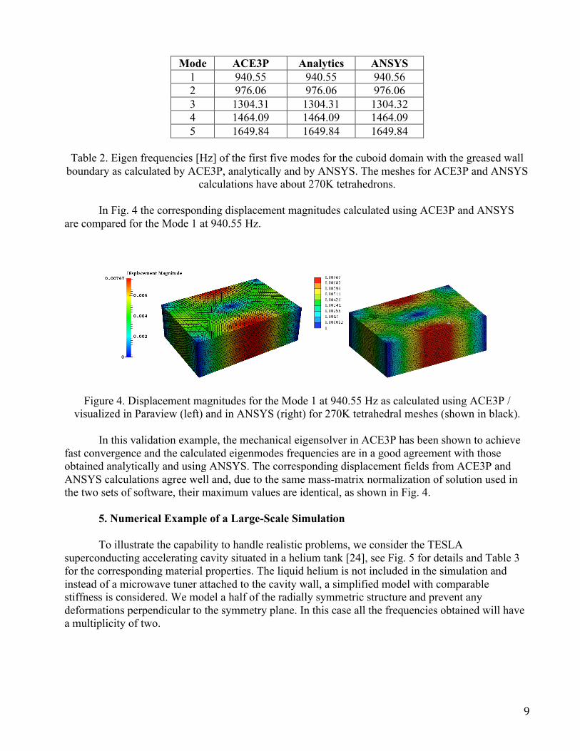
Mode ACE3P Ansys 1 74.18 73.84 2 74.18 73.84 3 160.92 160.59 4 160.92 160.59 5 220.12 219.08
Table 5. Eigen frequencies [Hz] of the first five eigenmodes for the TESLA superconducting cavity
as calculated by ACE3P and ANSYS.
The eigen frequencies are in a good agreement and a small discrepancy here is attribute to the mesh convergence in ANSYS that, if studied for such a complicated geometry, would require significant amount of time on a conventional computer.
In Fig. 6 the displacement magnitudes are presented for the first eigenmode at 74.18 Hz as calculated by ACE3P and ANSYS. The deformation field patterns are also quite similar and the magnitude scale maximum is identical in both simulations.
Figure 6. Displacement magnitudes for the first mode as calculated by ACE3P (top) and ANSYS (bottom) plotted on top of the undeformed geometry.
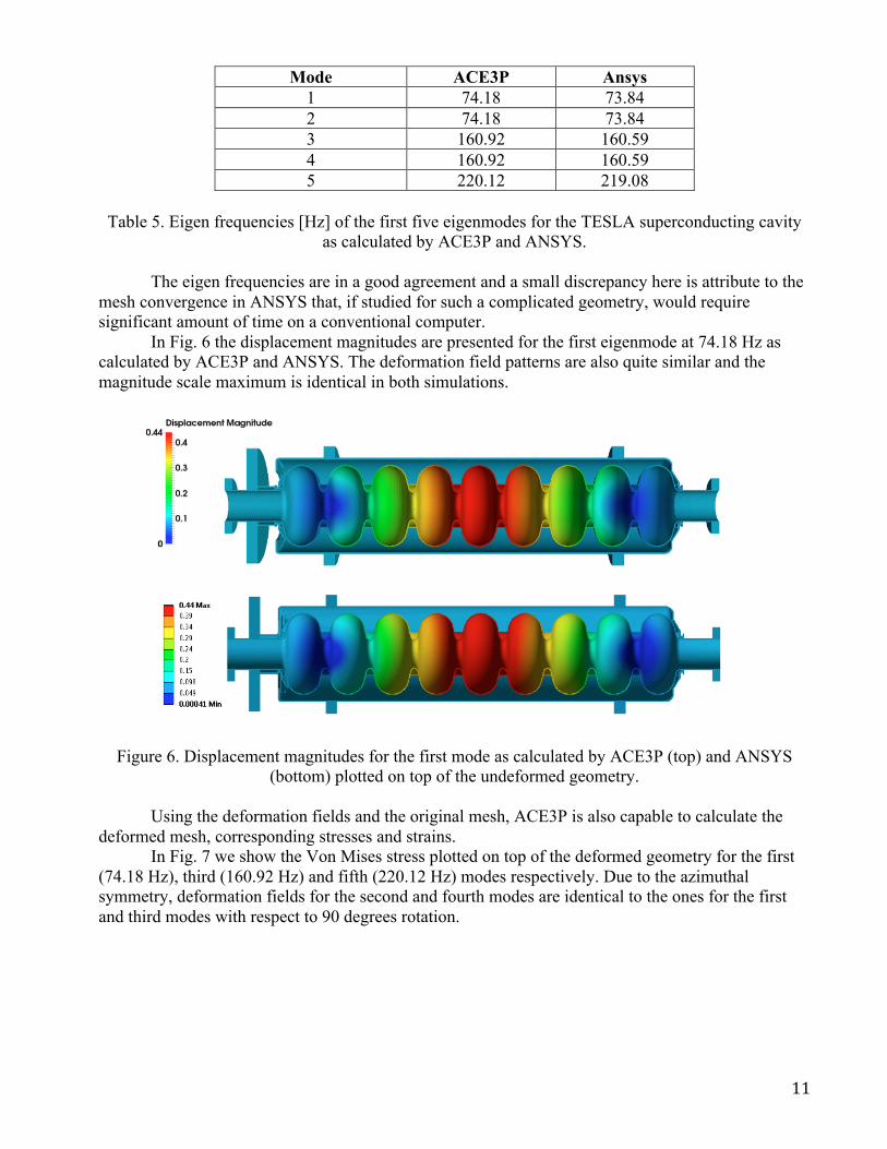
Using the deformation fields and the original mesh, ACE3P is also capable to calculate the deformed mesh, corresponding stresses and strains.
In Fig. 7 we show the Von Mises stress plotted on top of the deformed geometry for the first (74.18 Hz), third (160.92 Hz) and fifth (220.12 Hz) modes respectively. Due to the azimuthal symmetry, deformation fields for the second and fourth modes are identical to the ones for the first and third modes with respect to 90 degrees rotation.
12
Figure 7. Von Mises stress [a.u.] in logarithmic scale for the first mode at 74.18 Hz (top), third mode at 160.92 Hz (middle) and fifth mode at 220.12 Hz (bottom) as calculated by ACE3P and plotted on
top of the deformed geometry. The deformations are scaled for the visual purpose.
The main advantage of the developed ACE3P eigenvalue solver, i.e. the capability to perform a time-efficient accurate modal analysis of the complicated mechanical structures utilizing supercomputer resources, has been demonstrated. It is shown, see Table 4, that based on this approach, the solution for a problem with millions degrees of freedom can be processed in seconds.
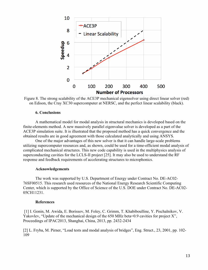
As discussed in Section 3, the mechanical eigensolver uses the eigensolvers implemented in the Omega3P module of ACE3P. Each of these eigensolvers requires the solution of a linear system using a direct or an iterative solver. In Fig. 8 the strong scalability of the mechanical eigensolver using a direct linear solver on Edison, the Cray XC30 supercomputer at NERSC, is compared against the perfect linear scalability. It can be seen that for the simulation profile described in Table 4 it scales fairly well up to 400 processors
The scalability of the developed mechanical eigenvalue solver can be further improved by using the iterative linear solvers with relevant preconditioners, which have been discussed in details in [19].
13
Figure 8. The strong scalability of the ACE3P mechanical eigensolver using direct linear solver (red)
on Edison, the Cray XC30 supercomputer at NERSC, and the perfect linear scalability (black). 6. Conclusions
A mathematical model for modal analysis in structural mechanics is developed based on the
finite-elements method. A new massively parallel eigenvalue solver is developed as a part of the ACE3P simulation suite. It is illustrated that the proposed method has a quick convergence and the obtained results are in good agreement with those calculated analytically and using ANSYS.
One of the major advantages of this new solver is that it can handle large-scale problems utilizing supercomputer resources and, as shown, could be used for a time-efficient modal analysis of complicated mechanical structures. This new code capability is used in the multiphysics analysis of superconducting cavities for the LCLS-II project [25]. It may also be used to understand the RF response and feedback requirements of accelerating structures to microphonics.
Acknowledgements
The work was supported by U.S. Department of Energy under Contract No. DE-AC02-
76SF00515. This research used resources of the National Energy Research Scientific Computing Center, which is supported by the Office of Science of the U.S. DOE under Contract No. DE-AC02-05CH11231.
References [1] I. Gonin, M. Awida, E. Borissov, M. Foley, C. Grimm, T. Khabiboulline, Y. Pischalnikov, V. Yakovlev, “Update of the mechanical design of the 650 MHz beta=0.9 cavities for project X”, Proceedings of IPAC2013, Shanghai, China, 2013, pp. 2432-2434 [2] L. Fryba, M. Pirner, “Load tests and modal analysis of bridges”, Eng. Struct., 23, 2001, pp. 102-109
14
[3] J. A. Abdalla, J. T. Petrovski, Y. E. A. Mohamedzein, "Vibration characteristics of a far field earthquake and its shaking effects on dubai emerging skyscrapers", The 14th World Conference on Earthquake Engineering, Beijing, China, 2008, 8 pages. [4] J. He, Z.-F. Fu, “Modal Analysis”, Butterworth-Heinemann, 2001, 304 pages [5] O. C. Zienkiewicz, R. L. Taylor, The finite element method for solid and structural mechanics, Butterworth-heinemann, 2005, 736 pages. [6] ACE3P Simulation Suite, SLAC National Accelerator Laboratory, http://www-group.slac.stanford.edu/acd/ [7] Kwok K, et al., Advances in parallel electromagnetic codes for accelerator science and development, Proceedings of Linear Accelerator Conference, Tsukuba, Japan, 2010, 5 pages [8] K. Lee, et al., Multiphysics Applications of ACE3P, Proceedings of International Particle Accelerator Conference, Luisiana, USA, 2012, 3 pages [9] L. Ge, K. Ko, K. Lee, Z. Li, C.-K, Ng, L. Xiao, Analyzing multipacting problems in accelerators using ACE3P on high performance computers, Proceedings of International Computational Accelerator Physics Conference, Rostock-‐Warnemünde, Germany, 2012, 5 pages [10] W. S. Slaughter, The linearized theory of elasticity, Birkhauser, 2002, 543 pages. [11] Strauss, Walter A. "Partial differential equations: An introduction." New York, 1992, 454 pages. [12] D.-K. Sun, J.-F. Lee, Z. Cendes, Construction of nearly orthogonal Nedelec bases for rapid convergence with multilevel preconditioned solvers, SIAM Journal on Scientific Computing, Vol. 23, No. 4, 2001, pp. 1053-1076. [13] V. Akcelik, A. Candel, A. Kabel, L-Q. Lee, Z. Li, C-K. Ng, L. Xiao and K. Ko, Parallel computation of integrated electromagnetic, thermal and structural effects for accelerator cavities, SLAC-PUB-13280, SLAC National Accelerator Laboratory, 2008, 3 pages. [14] National Energy Research Scientific Computing Center, Office of Science and U.S. Department of Energy, http://www.nersc.gov/ [15] Cubit, Geometry and mesh generation toolkit, Sandia National Laboratories, https://cubit.sandia.gov/ [16] Rew, Russ, and Glenn Davis. "NetCDF: an interface for scientific data access." Computer Graphics and Applications, IEEE 10.4, 1990, pp 76-82. [17] Karypis, George, Kirk Schloegel, and Vipin Kumar. "Parmetis." Parallel graph partitioning and sparse matrix ordering library. Version 2 (2003).

15
[18] K. Devine, E. Boman, R. Heaphy, B. Hendrickson, and C. Vaughan, “Zoltan data management services for parallel dynamic applications,” Computing in Science and Engineering, Vol. 4, No. 2, 2002, pp. 90-97. [19] L.-Q. Lee, Z. Li, C. Ng, K. Ko, Omega3P: a parallel finite-element eigenmode analysis code for accelerator cavities, SLAC-PUB-13529, SLAC National Accelerator Laboratory, 2009, 7 pages. [20] Paraview, Data analysis and visualization application, http://www.paraview.org/ [21] SLAC Toolbar for Paraview, http://www.slac.stanford.edu/~cho/cw11/cw11_manual/ParaView.pdf [22] D. Day, L. Romero, An analytically solvable eigenvalue problem for the linear elasticity equations, SAND2004-3310, Sandia National Laboratories, 2004, 13 pages. [23] ANSYS Workbench, Release 15.0 [24] B. Aune, R. Bandelmann, D. Bloess, B. Bonin, A. Bosotti, M. Champion, C. Crawford et al. "Superconducting TESLA cavities", Physical Review Special Topics-Accelerators and Beams, Vol. 3, No. 9, 2000, 25 pages. [25] Z. Li, L. Xiao, O. Kononenko, C. Adolphsen, M. Ross, T. Raubenheimer, “Multi-Physics Analysis of CW Superconducting Cavity For the LCLS-II Using ACE3P”, 5th International Particle Accelerator Conference, 2014, Dresden, Germany