a low cost air hybrid concept - ifpen
TRANSCRIPT
A Low Cost Air Hybrid ConceptC.Y. Lee, H. Zhao and T. Ma
School of Engineering and Design, Brunel University, Uxbridge, UB8 3PH - UKe-mail: [email protected] - [email protected] - [email protected]
Résumé — Un concept hybride à air et à bas prix — Le moteur hybride à air absorbe l’énergiecinétique du véhicule en cas de freinage, la stocke sous forme d’air comprimé, puis la réutilise pour faireavancer le véhicule en circulation ou en accélération. Capter, stocker et réutiliser cette énergie et créerainsi une puissance plus importante peut donc permettre de plus grandes économies de carburant, surtouten ville et zone urbaine, lorsque les conditions de circulation imposent de nombreux arrêts et démarrages.Pour pouvoir réutiliser l’énergie cinétique, on distingue trois modes de base d’utilisation du véhicule : lesmodes compression (MC), expansion (ME) et standard. Un moteur hybride à air et à bas prix a étéproposé et étudié. Un tel moteur peut être opéré par le biais de technologies de production, comme leVVT et la désactivation des soupapes. Dans ce travail, des analyses systématiques de performance ont étémenées via des modèles dynamiques détaillés utilisant le logiciel Ricardo WAVE. Une optimisation dessoupapes a été effectuée dans l’objectif d’un fonctionnement plus efficace du système et pour obtenir unepression effective moyenne de freinage plus élevée pour les modes MC et ME, respectivement.
Abstract — A Low Cost Air Hybrid Concept — The air hybrid engine absorbs the vehicle kinetic energyduring braking, stores it in an air tank in the form of compressed air, and reuses it to propel a vehicleduring cruising and acceleration. Capturing, storing and reusing this braking energy to give additionalpower can therefore improve fuel economy, particularly in cities and urban areas where the traffic condi-tions involve many stops and starts. In order to reuse the residual kinetic energy, the vehicle operationconsists of 3 basic modes, i.e. Compression Mode (CM), Expander Mode (EM) and normal firing mode.Unlike previous works, a low cost air hybrid engine has been proposed and studied. The hybrid engineoperation can be realized by means of production technologies, such as VVT and valve deactivation. Inthis work, systematic investigation has been carried out on the performance of the hybrid engine conceptthrough detailed gas dynamic modelling using Ricardo WAVE software. Valve timing optimization hasbeen done for the more efficient operation of air hybrid operation and obtaining higher braking andmotoring mean effective pressure for CM and EM respectively.
Oil & Gas Science and Technology – Rev. IFP, Vol. 65 (2010), No. 1, pp. 19-26Copyright © 2010, Institut français du pétroleDOI: 10.2516/ogst/2009089
Advances in Hybrid PowertrainsÉvolution des motorisations hybrides
IFP International ConferenceRencontres Scientifiques de l’IFP
02_ogst09028 17/02/10 10:39 Page 19
Oil & Gas Science and Technology – Rev. IFP, Vol. 65 (2010), No. 1
INTRODUCTION
While the traffic conditions involve frequent vehicle stopsand starts, a large amount of fuel is needed to accelerate thevehicle, and some of this is converted to heat in brake frictionduring deceleration. However, a dramatic amount of fuel canbe saved by using the momentum of the vehicle during coast-ing and deceleration to drive an air compressor so that thecompressed air can be stored and later used to power thevehicle during cruising and acceleration.
In the previous proposed air hybrid concepts [1-8], the airhybrid operation requires the use of fully variable valve actu-ation systems, weather it is electromechanical, hydraulic, orpneumatic camless system. Simulations made by Tai et al.[1] show round-trip efficiency of 36%, 38% reduction infuel consumption and 64% fuel economy improvement.Trajkovic et al. [8] made real engine experiments show aregenerative efficiency of 40-48% has been achieved.However, such complex camless systems are limited toresearch engines and they are unlikely to be suited for pro-duction in the short term. In this work, an alternative airhybrid concept with production technologies has been pro-posed and analysed. In this concept, a Cam Profile Switchingsystem (CPS) is utilized to control an intake valve in eachcylinder to operate the engine as an air compressor or an airexpander, in conjunction with an one-way valve in the intakeport and an external air tank valve.
A Ford PUMA 2 Litre diesel engine has been modelled asan air hybrid engine by using Ricardo’s WAVE software,which is an engine simulation tool to model the gas dynamicsand engine performance.
1 CONFIGURATION OF THE AIR HYBRID ENGINE
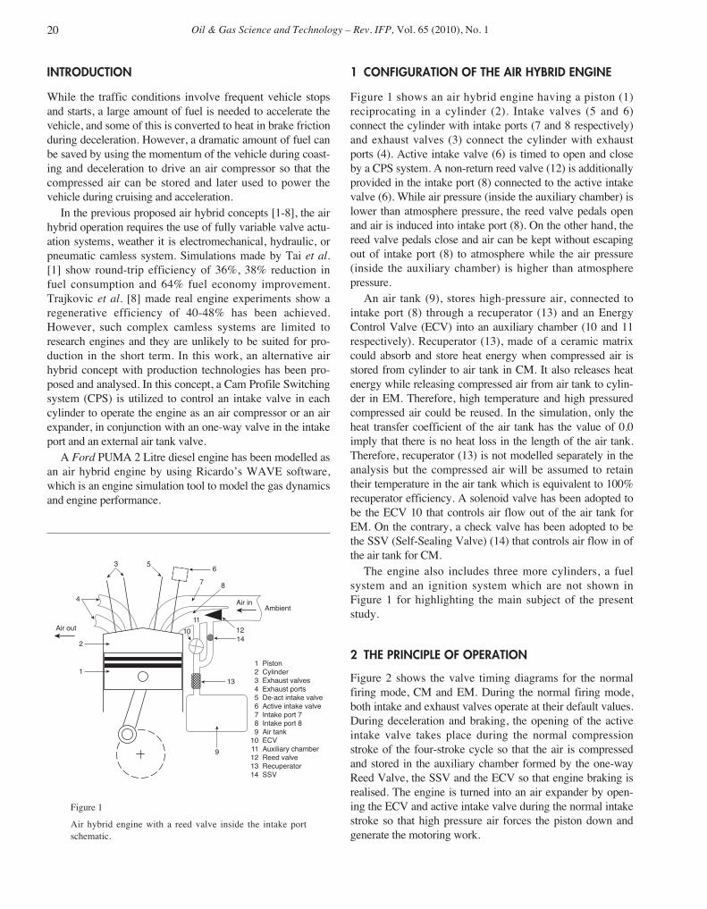
Figure 1 shows an air hybrid engine having a piston (1)reciprocating in a cylinder (2). Intake valves (5 and 6)connect the cylinder with intake ports (7 and 8 respectively)and exhaust valves (3) connect the cylinder with exhaustports (4). Active intake valve (6) is timed to open and closeby a CPS system. A non-return reed valve (12) is additionallyprovided in the intake port (8) connected to the active intakevalve (6). While air pressure (inside the auxiliary chamber) islower than atmosphere pressure, the reed valve pedals openand air is induced into intake port (8). On the other hand, thereed valve pedals close and air can be kept without escapingout of intake port (8) to atmosphere while the air pressure(inside the auxiliary chamber) is higher than atmospherepressure.
An air tank (9), stores high-pressure air, connected tointake port (8) through a recuperator (13) and an EnergyControl Valve (ECV) into an auxiliary chamber (10 and 11respectively). Recuperator (13), made of a ceramic matrixcould absorb and store heat energy when compressed air isstored from cylinder to air tank in CM. It also releases heatenergy while releasing compressed air from air tank to cylin-der in EM. Therefore, high temperature and high pressuredcompressed air could be reused. In the simulation, only theheat transfer coefficient of the air tank has the value of 0.0imply that there is no heat loss in the length of the air tank.Therefore, recuperator (13) is not modelled separately in theanalysis but the compressed air will be assumed to retaintheir temperature in the air tank which is equivalent to 100%recuperator efficiency. A solenoid valve has been adopted tobe the ECV 10 that controls air flow out of the air tank forEM. On the contrary, a check valve has been adopted to bethe SSV (Self-Sealing Valve) (14) that controls air flow in ofthe air tank for CM.
The engine also includes three more cylinders, a fuelsystem and an ignition system which are not shown inFigure 1 for highlighting the main subject of the presentstudy.
2 THE PRINCIPLE OF OPERATION
Figure 2 shows the valve timing diagrams for the normalfiring mode, CM and EM. During the normal firing mode,both intake and exhaust valves operate at their default values.During deceleration and braking, the opening of the activeintake valve takes place during the normal compressionstroke of the four-stroke cycle so that the air is compressedand stored in the auxiliary chamber formed by the one-wayReed Valve, the SSV and the ECV so that engine braking isrealised. The engine is turned into an air expander by open-ing the ECV and active intake valve during the normal intakestroke so that high pressure air forces the piston down andgenerate the motoring work.
20
Air out
1 Piston 2 Cylinder 3 Exhaust valves 4 Exhaust ports 5 De-act intake valve 6 Active intake valve 7 Intake port 7 8 Intake port 8 9 Air tank 10 ECV 11 Auxiliary chamber 12 Reed valve 13 Recuperator 14 SSV
Air in
1
2
3
4
56
7 8
12
Ambient
14
9
10
11
13
Figure 1
Air hybrid engine with a reed valve inside the intake portschematic.
02_ogst09028 17/02/10 10:39 Page 20

The key feature of this new concept is the auxiliarychamber and the ECV acting as a buffer between the enginecylinder and the air storage tank.
The size of the auxiliary chamber volume is an importantparameter in this concept. It is determined by the position ofthe non-return reed valve, the position of the SSV and theposition of the ECV. The geometric compression ratio of theengine is 18.4:1 for a CI engine in the normal firing mode(the engine displacement volume and clearance volume are500 cm3 and 28.7 cm3 per cylinder respectively). However,when the engine is switched to the compression mode, theactual compression ratio (Rc) decreases as the volume of theauxiliary chamber is included in the cylinders’ total clearancevolume. For the auxiliary chamber volume of 67.7 cm3
examined below, the actual compression ratio is calculated as:
(1)
During CM, air is compressed into the auxiliary chamberisolated by the ECV and the SSV from the air storage tank,and then released by the SSV into the air storage tank due tothe pressure difference between the auxiliary chamber andthe air storage tank. During EM, the ECV controls theamount of compressed air released from the air storage tankto the auxiliary chamber and then goes into the cylinder afterthe intake valve is opened.
Without the auxiliary chamber and ECV, the intake valvehas to be able to vary its opening profile in order to controlthe amount of compressed air released from the air storagetank. By adopting the auxiliary chamber and the ECV, thecomplicated and expensive active valve control system couldbe avoided in the engine design. For example, the valve actu-ation system has been adopted with a camless hydraulicvalve actuator system in recent research [7-8].
Rc =+ +
+=
500 28 7 96 4
28 7 96 45 0 1
. .
. .. :
3 SIMULATION AND RESULTS
3.1 Engine Simulation Setup
The modelled air hybrid engine was based on a Ford PUMA2L diesel engine with four cylinders and the air hybridoperation was simulated in Ricardo’s WAVE software. Thesimulation analyzes the dynamics of pressure waves, massflows, and energy losses in ducts, plenums, and the mani-folds of the engine. Engine and valves data are given in Table1 and Table 2 respectively. A 40 Litre air tank has been usedin this model. Its pressure range is between 5 and 20 bar inthe simulation.
TABLE 1
Engine dimensions and characteristics
Number of cylinders 4
Cylinder bore 86 mm
Piston stroke 86 mm
Connecting rod length 160 mm
Displacement volume 500 cm3
Clearance volume 28.7 cm3
Total volume of one cylinder 528.7 cm3
Compression ratio 18.4:1
Rc for air hybrid mode (a) 5.0:1
Compressed Air Transfer Coefficient (CATC) has beenintroduced to indicate the efficiency of the air hybrid brakingprocess. It is defined as the ratio of air mass transferred to theair tank from the cylinder to air mass transferred to the cylin-der from the atmosphere, as given by Equation (2):
(2)
and it is a measure of the fraction of the vehicle’s kineticenergy which can be stored in the air reservoir in the form ofpotential energy.
The potential of work of each unit of air mass capturedduring the compression mode is described by the brakingspecific indicated mean effective pressure (imepb), which isthe ratio of imep and air mass transferred to the air tank:
(3)
The output of work per unit mass during the expansionmode is represented by the motoring specific indicated meaneffective pressure (imepm):
(4)Specific imep =mair, gtv
imepmm
Specific imepb =imepb
mair, gtv
CATCb =mair, gtv
mair, in
CY Lee et al. / A Low Cost Air Hybrid Concept 21
Normalfiring mode
Intake Compression Expansion Exhaust
Compressionmode
Expandermode
Intake valve
Active intake valve
ECV
Exhaust valve
SSV
Figure 2
Engine valves, active intake valve and ECV timing fornormal firing mode, CM and EM.
02_ogst09028 17/02/10 10:39 Page 21

Oil & Gas Science and Technology – Rev. IFP, Vol. 65 (2010), No. 1
Furthermore, the regenerative efficiency is represented bythe ratio of the motoring specific imep and braking specificimep:
(5)
3.2 Active Intake Valve Shiftingand ECV Opening Timing for CM
The optimum control of the compression work is to find thebest active intake valve closing timing for maximum brakingperformance, as defined by the calculated Compressed AirTransfer Coefficient (CATC), and braking work obtained.
CATCb depends on the gas dynamics of the intake systemand the auxiliary chamber. Figure 3 shows that maximumCATCb is realized when the active IVC is at 50° ATDCwith IVO at 30° BBDC. The active intake valve closing at50° ATDC prevents backflow of the compressed air, pro-viding maximum air transfer efficiency. For earlier IVCs,it has not enough time to accumulate compressed air fromcylinders to the tank due to short opening duration (fromTDC to IVCs). On the other hand, very late IVC timingsresults in more compressed air flowing back into the cylin-der and wasted. Furthermore, CATCb is higher at low tankpressure because at lower back pressure the more inductedair can be compressed in to the tank.
Figure 4 shows the predicted variation of imepb (shownthe absolute values) in regard to active IVC points for thetank pressure range between 5 and 20 bar, at intervals of
ηregen =Specific imep
Specific imepm
b
5 bar. It can be seen from the results that high brakingperformance is achieved for a range of active IVC timingsbetween 40°-60° CA ATDC, where increased imepb (andhence braking torque) is realized. Imepb drops rapidly if IVCis shifted out of the above range, while peak imepb isachieved at 50° CA, regardless the tank pressure. It shouldnote that the actual braking torque exerted to the vehicle willinclude the frictional torque and hence the braking bmepwill be typically 1 bar above the values shown in Figure 4.
However, braking specific imep (braking imep per unit ofinduced air mass compressed in to the tank) shows theenergy capture and storage ability. Smaller braking specificimep shows higher energy capture and storage ability.Figure 5 shows the best energy capture and storage abilityhappens at 60° active IVC and 80° active IVC for 15 bar tankpressure and the tank pressure between 5 bar and 10 barrespectively. The peaks in the braking specific imep valuesare caused by the least amount of air compressed into the airtank at very early or very retarded IVC timings.
The predicted cylinder indicator diagrams for variousvalve lift profile shifts are shown in Figure 6 at 2000 rpmengine speed and 5 bar tank pressure. In Figure 6, the muchhigher peak cylinder pressure shows while active IVC pointis at 30° ATDC due to the advanced active IVC during thecompression stroke. For active IV closing at 50° ATDC, thebigger Area B, comparing to Area A and Area C, reflectshigher imepb.
Based on the above investigation, Figure 7 shows optimalactive intake valve and check valve timing in the same dia-gram together with engine valve timing. For a simple CPSsystem, closing time of Active intake valve is fixed at 60°ATDC at any tank pressures.
22
TABLE 2
Valves dimensions and characteristics
Intake valve 2
Diameter 23.5 mm
Opening point (normal) 20° BTDC
Closing point (normal) 60° ABDC
Maximum lift 8.75 mm
Exhaust valve 1
Diameter 23.4 mm
Opening point 60° BBDC
Closing point 35° ATDC
Maximum lift 8.75 mm
Reed valve 1
Pedal stiffness 1900 N/m
Maximum lift 9 mm
ECV count 1
Diameter 24.9 mm
70 806050403020100
Bra
king
CA
TC
(%
)
90
0
80
70
60
50
40
30
20
10
Active IVC (deg CA); 0 = compression TDC
5 bar
10 bar
15 bar
Figure 3
Predicted CATCb for 2000 rpm engine speed.
02_ogst09028 17/02/10 10:39 Page 22

3.3 Valves Timing Optimization for EM
During EM, air is released by the ECV after the active intakevalve is opened, and the quantity of air is controlled by ECVclose timing while the active intake valve stays open and theair in the auxiliary chamber expands into the engine cylinder.To prevent compressed air from escaping, Intake valve (5) isdeactivated in the intake stroke.
Although, as more compressed air expands in cylindershigher motoring work will be produced, some of the air couldbe wasted if the expansion process is incomplete. The amount
of air should be controlled to produce a full expansionprocess through the optimisation of ECV timings. Therefore,the aim of optimised EM operation is to generate the highestvalues of power per unit mass by finding the best ECVclosing timing through modelling its timing shift.
The sensitivity of predicted mass of air transferred duringone engine cycle to ECV closing points for various air tankpressures is shown in Figure 8. The ECV opening point isfixed at compression TDC. It can be seen that compressed airexpenditure increases for longer ECV opening duration tillthe end of BDC.
CY Lee et al. / A Low Cost Air Hybrid Concept 23
10 8020 30 40 50 60 700
Bra
king
imep
(ba
r)4.5
0
0.5
1.0
1.5
2.0
2.5
3.0
3.5
4.0
Active IVC (deg CA); 0 = compression TDC
5 bar
10 bar
15 bar
Figure 4
Predicted imepb for 2000 rpm engine speed.
70 806050403020100
Bra
king
spe
cific
imep
(ba
r/g)
40
0
35
30
25
20
15
10
5
Active IVC (deg CA); 0 = compression TDC
5 bar
10 bar
15 bar
Figure 5
Braking specific imep for 2000 rpm engine speed.
15 201050
Cyl
inde
r pr
essu
re (
bar)
18
0
16
14
12
10
8
6
4
2
Volume (clearance volume)
30A TDC
50A TDC
80A TDC
AC
B
Figure 6
Indicator diagram for various active IVC timings.
720540360ExhaustExpansion Intake Compression1800
Val
ve li
ft (m
m)
10
0
9
8
7
6
5
4
3
2
1
CA (deg); 0 = compression TDC
Exhaustvalve
Intakevalve 5
Active intakevalve
SSV
Figure 7
Optimal active intake valve timing for air compressor mode.
02_ogst09028 17/02/10 10:39 Page 23

Oil & Gas Science and Technology – Rev. IFP, Vol. 65 (2010), No. 1
Figure 9 shows the sensitivity of the predicted imepm toECV closing points for various air tank pressures. It can beseen that imepm is a strong function of air tank pressure andproportional to it. Imepm increases for retarded ECV clos-ings. However, the ratio of compressed air expenditure toimepm practically represents the ability of the air expanderwhich is shown in Figure 10. For various air tank pressuresand ECV closing points, higher motoring specific imep indi-cates that compressed air is more efficiently consumed whenECV closes at 10°, 30° and 50° BBDC for 5, 10 and 15 bartank pressures respectively.
Figure 11 shows that, with intake valve 5 deactivated,cylinder pressure remains at 5 bar for the optimised ECV
timing at the bottom of the real expansion process whichcorresponds to the intake stroke in the normal firing mode.Ideally, the final state at the end of the expansion processshould reach ambient pressure for maximum expansionwork. Otherwise, remaining high pressure air will causenegative work during the subsequent compression stroke.Therefore, it could be advantageous to open the intakevalve (5) near the end of the expansion to relief pressurebuilt up in the cylinder during the subsequent compressionstroke.
Through systematic studies, it was found that when theopening timing of Intake valve (5) shifts to 110° BBDC atthe expansion process (the normal intake stroke), cylinder
24
-10 0-20-30-40-50-60-70-80-90
Com
pres
sed
air
expe
nditu
re (
kg)
0.0025
0
0.0005
0.0010
0.0015
0.0020
ECVC (deg CA); 0 = compression BDC
5 bar
10 bar
15 bar
Figure 8
Compressed air expenditure for 2000 rpm engine speed.
0-80 -70 -60 -50 -40 -30 -20 -10-90
Mot
orin
g im
ep (
bar)
3.5
0
0.5
1.0
1.5
2.0
2.5
3.0
ECVC (deg CA); 0 = compression BDC
5 bar
10 bar
15 bar
Figure 9
Predicted imepm for 2000 rpm engine speed.
Figure 11
Pressure diagram for air expander mode.
720540360ExhaustExpansion Intake Compression1800
Pre
ssur
e (b
ar)
36
0
343230282624222018161412108642
CA (deg); 0 = compression TDC
TankAuxiliary chamber
Cylinder
Figure 10
Motoring specific imep for 2000 rpm engine speed.
0-80 -70 -60 -50 -40 -30 -20 -10-90
Mot
orin
g sp
ecifi
c im
ep (
bar/
g)
0.50
0
0.45
0.40
0.35
0.30
0.25
0.20
0.15
0.10
0.05
ECVC (deg CA); 0 = compression BDC
5 bar
10 bar
15 bar
02_ogst09028 17/02/10 10:39 Page 24

pressure decreases to the ambient pressure at the end of thereal expansion process as shown in Figure 12. Because of thereduced negative work and full expansion, much highermotoring imepm values are generated. This is confirmed bycomparing results in Figure 9 and Figure 13. At 10 bar tankpressure, the maximum motoring imep is increased from1.7 bar to 4.3 bar, and at 15 bar tank pressure it is increasedfrom 3.2 bar to 7.1 bar.
Because the amount of compressed air expenditure iscontrolled by ECV closing timing, opening of Intake valve 5at 110° BBDC at the intake stroke doesn’t affect its values.Figure 14 shows that higher motoring specific imep obtainedwhen ECV closes at 40°, 80° and 90° BBDC for 5, 10, and
15 bar tank pressures respectively. Comparing Figures 10and 14, maximum motoring specific imep values areincreased by more than 120%.
Figure 15 shows the predicted cylinder indicator dia-grams for various ECV lift profiles at 2000 rpm enginespeed and 10 bar tank pressure. In Figure 15, the muchhigher peak cylinder pressure shows while ECVC point isat BDC, comparing to ECVC point is at 90 BBDC,because the much bigger overlap between the active intakevalve lift profile and the ECV lift profile released morecompressed air into the auxiliary chamber and the cylinderand then generating higher peak cylinder pressure duringcompression stroke.
CY Lee et al. / A Low Cost Air Hybrid Concept 25
720540360ExhaustExpansion Intake Compression1800
Pre
ssur
e (b
ar)
36
0
343230282624222018161412108642
CA (deg); 0 = compression TDC
TankAuxiliary chamber
Cylinder
Figure 12
Pressure diagram for air expander mode (without deactivatingIntake valve 5).
-80 0-70 -60 -50 -40 -30 -20 -10-90
Mot
orin
g im
ep (
bar)
8
0
1
2
3
4
5
6
7
ECVC (deg CA); 0 = compression BDC
5 bar
10 bar
15 bar
Figure 13
Predicted imepm for 2000 rpm engine speed (withoutdeactivating Intake valve 5).
Figure 14
Motoring specific imep for 2000 rpm engine speed (withoutdeactivating Intake valve 5).
-80 0-70 -60 -50 -40 -30 -20 -10-90
Mot
orin
g sp
ecifi
c im
ep (
bar/
g)
1.4
0
1.2
1.0
0.8
0.6
0.4
0.2
ECVC (deg CA); 0 = compression BDC
5 bar
10 bar
15 bar
Figure 15
Indicator diagram for various ECVC timing.
15 201050
Cyl
inde
r pr
essu
re (
bar)
40
0
35
30
25
20
15
10
5
Volume (clearance volume)
ECVC 90 BBDC
ECVC 0 BDC
02_ogst09028 17/02/10 10:39 Page 25

Oil & Gas Science and Technology – Rev. IFP, Vol. 65 (2010), No. 1
Finally, Figure 16 shows the optimal ECV timing andIntake valve (5) timing according to the above investigation.The exhaust and active intake valve timings are also shownin the same diagram. While tank pressure works between10-15 bar, ECV closing timing could be fixed at 80° BBDC.
CONCLUSION
A low cost air hybrid engine concept has been proposed andanalysed. The concept can be realised with current produc-tion technologies and it does not require the use of camlesstechnologies that other air hybrid engine concepts mandate.Both compression mode and expansion mode operations canbe effectively operated with the use of VVTs on the intakevalves and external solenoid valves for transferring the com-pression air between the cylinders and the air tank.
Analytical studies have shown that valves timings havesignificant effects on the performance of compression modeand expansion mode operations in the proposed air hybridconcept. The closing timing of the active intake valve can beoptimised for maximum braking work, while the closing tim-ing of the ECV valve determines the expansion work duringthe expansion mode operation. The ECV adopts a solenoid
26
Copyright © 2010 Institut français du pétrolePermission to make digital or hard copies of part or all of this work for personal or classroom use is granted without fee provided that copies are not madeor distributed for profit or commercial advantage and that copies bear this notice and the full citation on the first page. Copyrights for components of thiswork owned by others than IFP must be honored. Abstracting with credit is permitted. To copy otherwise, to republish, to post on servers, or to redistributeto lists, requires prior specific permission and/or a fee: Request permission from Documentation, Institut français du pétrole, fax. +33 1 47 52 70 78, or [email protected].
720540360ExhaustExpansion Intake Compression1800
Val
ve li
ft (m
m)
10
0
9
8
7
6
5
4
3
2
1
CA (deg); 0 = compression TDC
Intakevalve 5
Active intake valveExhaustvalve
ECV
Figure 16
Optimal ECV timing for air expander mode.
valve which is very easy to control opening and closingtiming. Positions of reed valves and the ECV also decideauxiliary chamber volume which affects its performance.
Table 3 shows a regenerative efficiency of 22-25% hasbeen achieved while tank pressure works between 10-15 bar.However, this concept of the air hybrid engine is very simplestructure. Both intake valves adopt a CPS system. The tank,reed valves and a recuperator are also low cost.
REFERENCES
1 Tai C., Tsao T. (2003) Using Camless Valvetrain for Air HybridOptimization, SAE paper 2003-01-0038.
2 The University of California, “UCLA Study Suggests AirHybrid Car Could Improve Fuel Efficiency”, obtained fromhttp://www.newsroom.ucla.edu/page.asp?id=4420, last visitedMarch 2007.
3 Schechter M. (1999) New Cycles for Automobile Engines, SAEpaper 1999-01-0623.
4 Schechter M. (2000) Regenerative Compression Braking –a Low Cost Alternative to Electric Hybrids, SAE paper2000-01-1025.
5 Turner J., Bassett M., Pearson R., Picher G., Douglas K. (2004)New Operating Strategies afforded by Fully Variable ValveTrains, SAE paper 2004-01-1386.
6 Turner J., Pearson R., Kenchington S.A. (2005) Concepts forImproved Fuel Economy from Gasoline Engines, Int. J. EngineRes. 6, 2, 137-157.
7 Trajkovic S., Tunestal P., Johansson B. (2008) Investigation ofDifferent Valve Geometries and Valve Timing Strategies andtheir Effect on Regenerative Efficiency for a Pneumatic Hybridwith Variable Valve Actuation, SAE paper 08SFL-0329.
8 Kang H., Tai C., Smith E., Wang X., Tsao T., Stewart J.,Blumberg P. (2008) Demonstration of Air-Power-Assist (APA)Engine Technology for Clean Combustion and Direct EnergyRecovery in Heavy Duty Application, SAE paper 2008-01-1197.
Final manuscript received in June 2009Published online in February 2010
TABLE 3
Regenerative efficiency for 2000 rpm engine speed
Air tankImepb Imepm
Regenerative
pressure efficiency
5 bar 2.4 0.47 19.58
10 bar 3.56 0.92 25.84
15 bar 5.4 1.19 22.04
02_ogst09028 17/02/10 10:39 Page 26