a-lign technical manual
TRANSCRIPT
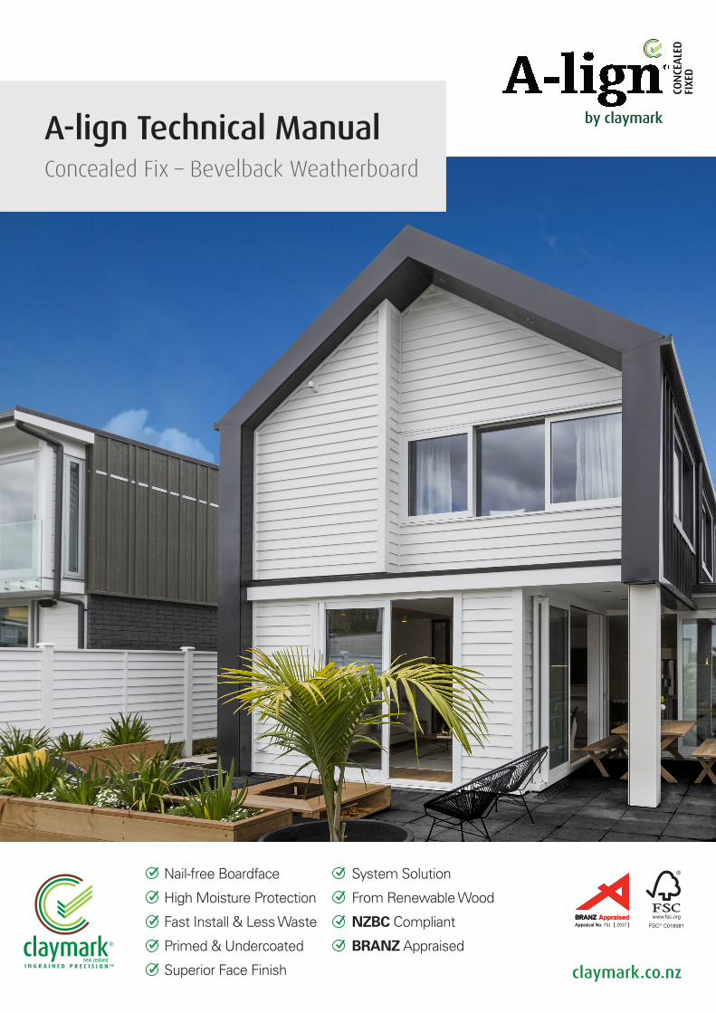
Nail-free Boardface
High Moisture Protection
Fast Install & Less Waste
Primed & Undercoated
Superior Face Finish
System Solution
From Renewable Wood
NZBC Compliant
BRANZ Appraised
A-lign Technical ManualConcealed Fix – Bevelback Weatherboard
claymark.co.nz
Appraisal No [ ]Appraisal No [ ]. 751 2017
* NZ Patent Nos. 549708 & 575988 NZ Patent Application No. 592576
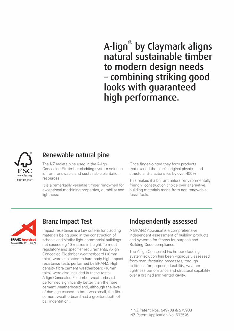
Renewable natural pineThe NZ radiata pine used in the A-lign Concealed Fix timber cladding system solution is from renewable and sustainable plantation resources.
It is a remarkably versatile timber renowned for exceptional machining properties, durability and lightness.
Once finger-jointed they form products that exceed the pine’s original physical and structural characteristics by over 400%.
This makes it a brilliant natural ‘environmentally friendly’ construction choice over alternative building materials made from non-renewable fossil fuels.
Branz Impact Test Impact resistance is a key criteria for cladding materials being used in the construction of schools and similar light commercial buildings not exceeding 10 metres in height. To meet regulatory and specifier requirements, A-lign Concealed Fix timber weatherboard (18mm thick) were subjected to hard body high impact resistance tests performed by BRANZ. High density fibre cement weatherboard (16mm thick) were also included in these tests. A-lign Concealed Fix timber weatherboard performed significantly better than the fibre cement weatherboard and, although the level of damage caused to both was small, the fibre cement weatherboard had a greater depth of ball indentation.
Independently assessedA BRANZ Appraisal is a comprehensive independent assessment of building products and systems for fitness for purpose and Building Code compliance.
The A-lign Concealed Fix timber cladding system solution has been vigorously assessed from manufacturing processes, through to fitness for purpose, durability, weather-tightness performance and structural capability over a drained and vented cavity.
A-lign® by Claymark aligns
natural sustainable timber to modern design needs – combining striking good looks with guaranteed high performance.
Appraisal No [ ]Appraisal No [ ]. 751 2017
© Claymark Limited 1
ALMOND
CLAYMARKRECOMMENDED BRAND APPROACH 14/06/17
EXPORT MARKETS
US
US
US
AUSTRALIA
AUSTRALIA
NZ DOMESTIC
by claymark
Profiles Select
Tru-Pine
by claymark
Solid gold™
by claymark
Centurion™
by claymarkG
by claymark
by claymark
by claymark
Premium Pineby claymark
A-LIGN COMPONENTS 2
A-LIGN NAILING SCHEDULE 3
INTRODUCTION 4
SPECIFICATIONS FOR EXTERIOR CLADDING 5
1.0 Before application of the cladding 5
2.0 A-lign bevelback weatherboard 52.1 A-lign bevelback weatherboard sizes 52.2 A-lign timber accessories 52.3 Accessories by Quickflash 5
3.0 Detailing 5
4.0 A-lign on site 54.1 Storage 54.2 Handling 5
5.0 Wall underlays 65.1 Non-rigid underlays 65.2 Rigid underlay installation 65.3 Building wrap installation 65.4 Synthetic wall wrap installation 7
6.0 Flashings 76.1 Supply 76.2 Materials 76.3 Fabrication and installation 7
7.0 Sealants 77.1 Materials 7
8.0 Air Seals 78.1 Materials 88.2 Installation 8
9.0 Drained and vented cavities 89.1 Design 89.2 Materials 89.3 Fixing A-lign battens 89.4 Cavity closure 9
10.0 Fixing A-lign bevelback weatherboard 910.1 Fixings 910.2 Fixing method 910.3 Setting out 910.4 Fixing procedure for bevelback weatherboard 910.5 Joining weatherboard 910.6 External box corners 1010.7 External mitred corners 1010.8 Internal corners 10
11.0 Window and door openings 1011.1 Aluminium windows 1011.2 Timber windows 1011.3 Flashings 1011.4 A-lign facings 1111.5 Air seals 11
12.0 Painting A-lign 1112.1 Materials 1112.2 Painting 11
13.0 General information 1113.1 Handling 1113.2 Installation 1113.3 Finishing 1113.4 Moisture 1113.5 Heat generating colours 12
14.0 Building maintenance 1214.1 New construction 1214.2 Regular washing 1214.3 Maintenance painting 12
A-LIGN WARRANTY 13
DRAWINGS DIRECTORY 14
SET OUT GUIDES 16
CAD DRAWINGS – cavity fixed 17 – 41
CLAYMARK – WARRANTY 42
Contents
2 © Claymark Limited
ALMOND
CLAYMARKRECOMMENDED BRAND APPROACH 14/06/17
EXPORT MARKETS
US
US
US
AUSTRALIA
AUSTRALIA
NZ DOMESTIC
by claymark
Profiles Select
Tru-Pine
by claymark
Solid gold™
by claymark
Centurion™
by claymarkG
by claymark
by claymark
by claymark
Premium Pineby claymark
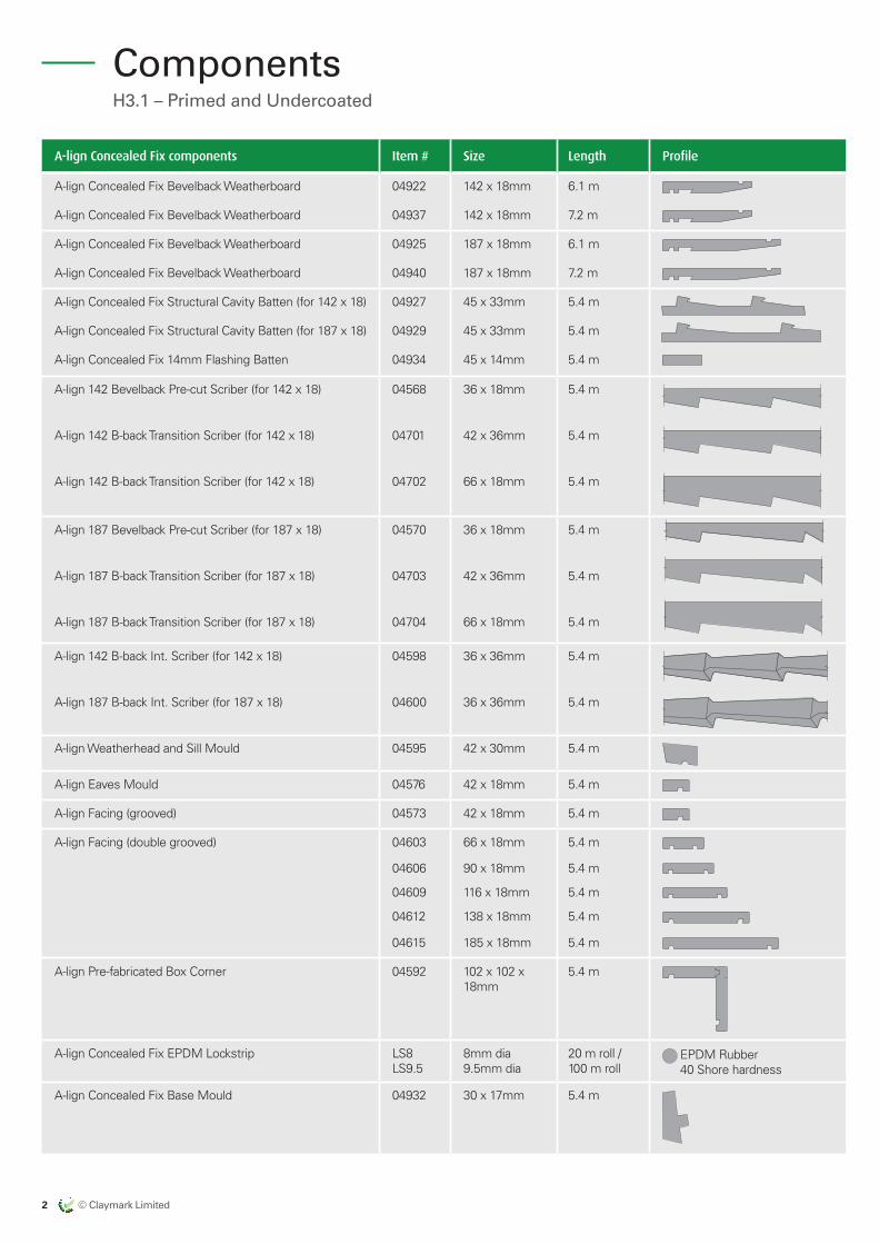
H3.1 – Primed and Undercoated
Components
A-lign Concealed Fix components Item # Size Length Profile
A-lign Concealed Fix Bevelback Weatherboard 04922 142 x 18mm 6.1 m
A-lign Concealed Fix Bevelback Weatherboard 04937 142 x 18mm 7.2 m
A-lign Concealed Fix Bevelback Weatherboard 04925 187 x 18mm 6.1 m
A-lign Concealed Fix Bevelback Weatherboard 04940 187 x 18mm 7.2 m
A-lign Concealed Fix Structural Cavity Batten (for 142 x 18) 04927 45 x 33mm 5.4 m
A-lign Concealed Fix Structural Cavity Batten (for 187 x 18) 04929 45 x 33mm 5.4 m
A-lign Concealed Fix 14mm Flashing Batten 04934 45 x 14mm 5.4 m
A-lign 142 Bevelback Pre-cut Scriber (for 142 x 18) 04568 36 x 18mm 5.4 m
A-lign 142 B-back Transition Scriber (for 142 x 18) 04701 42 x 36mm 5.4 m
A-lign 142 B-back Transition Scriber (for 142 x 18) 04702 66 x 18mm 5.4 m
A-lign 187 Bevelback Pre-cut Scriber (for 187 x 18) 04570 36 x 18mm 5.4 m
A-lign 187 B-back Transition Scriber (for 187 x 18) 04703 42 x 36mm 5.4 m
A-lign 187 B-back Transition Scriber (for 187 x 18) 04704 66 x 18mm 5.4 m
A-lign 142 B-back Int. Scriber (for 142 x 18) 04598 36 x 36mm 5.4 m
A-lign 187 B-back Int. Scriber (for 187 x 18) 04600 36 x 36mm 5.4 m
A-lign Weatherhead and Sill Mould 04595 42 x 30mm 5.4 m
A-lign Eaves Mould 04576 42 x 18mm 5.4 m
A-lign Facing (grooved) 04573 42 x 18mm 5.4 m
A-lign Facing (double grooved) 04603 66 x 18mm 5.4 m
04606 90 x 18mm 5.4 m
04609 116 x 18mm 5.4 m
04612 138 x 18mm 5.4 m
04615 185 x 18mm 5.4 m
A-lign Pre-fabricated Box Corner 04592 102 x 102 x 18mm
5.4 m
A-lign Concealed Fix EPDM Lockstrip LS8 LS9.5
8mm dia 9.5mm dia
20 m roll / 100 m roll
EPDM Rubber 40 Shore hardness
A-lign Concealed Fix Base Mould 04932 30 x 17mm 5.4 m
© Claymark Limited 3
ALMOND
CLAYMARKRECOMMENDED BRAND APPROACH 14/06/17
EXPORT MARKETS
US
US
US
AUSTRALIA
AUSTRALIA
NZ DOMESTIC
by claymark
Profiles Select
Tru-Pine
by claymark
Solid gold™
by claymark
Centurion™
by claymarkG
by claymark
by claymark
by claymark
Premium Pineby claymark
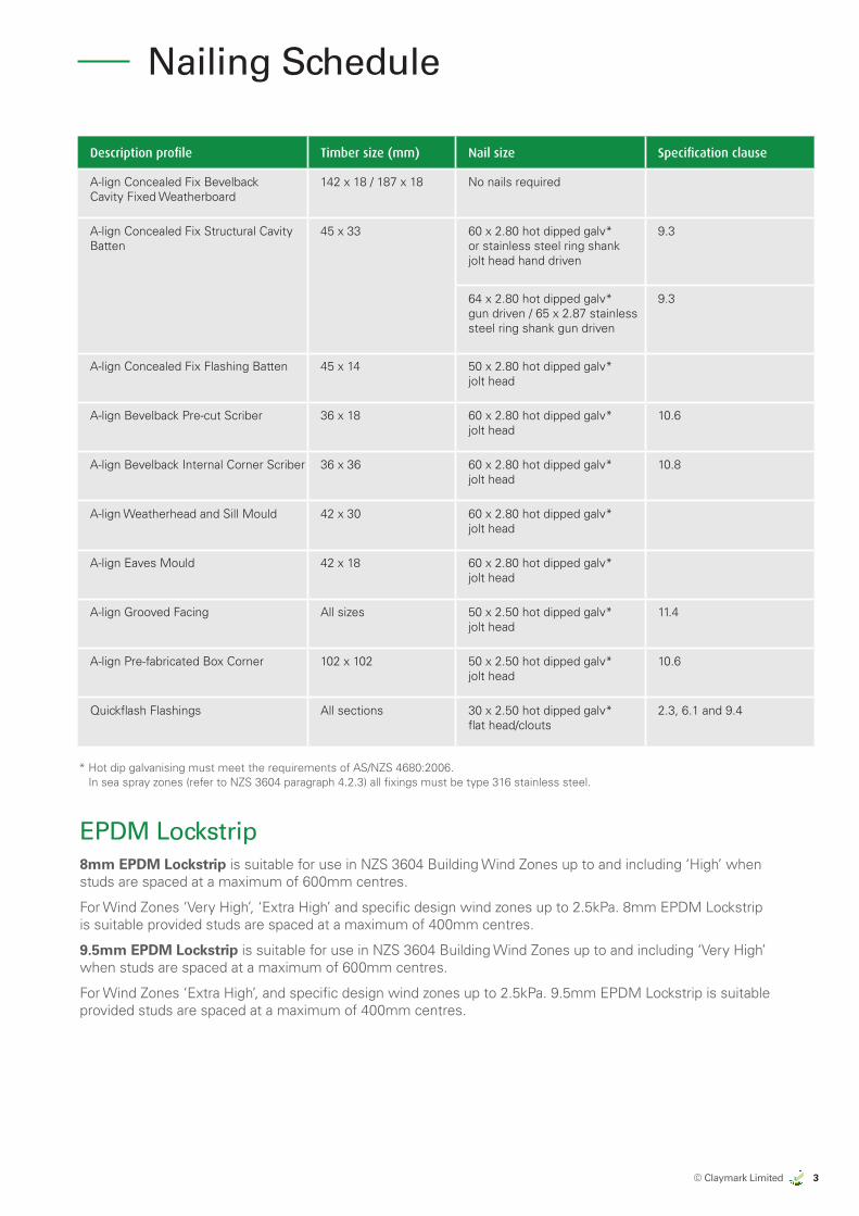
Nailing Schedule
EPDM Lockstrip8mm EPDM Lockstrip is suitable for use in NZS 3604 Building Wind Zones up to and including ‘High’ when studs are spaced at a maximum of 600mm centres.
For Wind Zones ‘Very High’, ‘Extra High’ and specific design wind zones up to 2.5kPa. 8mm EPDM Lockstrip is suitable provided studs are spaced at a maximum of 400mm centres.
9.5mm EPDM Lockstrip is suitable for use in NZS 3604 Building Wind Zones up to and including ‘Very High’ when studs are spaced at a maximum of 600mm centres.
For Wind Zones ‘Extra High’, and specific design wind zones up to 2.5kPa. 9.5mm EPDM Lockstrip is suitable provided studs are spaced at a maximum of 400mm centres.
Description profile Timber size (mm) Nail size Specification clause
A-lign Concealed Fix Bevelback Cavity Fixed Weatherboard
142 x 18 / 187 x 18 No nails required
A-lign Concealed Fix Structural Cavity Batten
45 x 33 60 x 2.80 hot dipped galv* or stainless steel ring shank jolt head hand driven
9.3
64 x 2.80 hot dipped galv* gun driven / 65 x 2.87 stainless steel ring shank gun driven
9.3
A-lign Concealed Fix Flashing Batten 45 x 14 50 x 2.80 hot dipped galv* jolt head
A-lign Bevelback Pre-cut Scriber 36 x 18 60 x 2.80 hot dipped galv* jolt head
10.6
A-lign Bevelback Internal Corner Scriber 36 x 36 60 x 2.80 hot dipped galv* jolt head
10.8
A-lign Weatherhead and Sill Mould 42 x 30 60 x 2.80 hot dipped galv* jolt head
A-lign Eaves Mould 42 x 18 60 x 2.80 hot dipped galv* jolt head
A-lign Grooved Facing All sizes 50 x 2.50 hot dipped galv* jolt head
11.4
A-lign Pre-fabricated Box Corner 102 x 102 50 x 2.50 hot dipped galv* jolt head
10.6
Quickflash Flashings All sections 30 x 2.50 hot dipped galv* flat head/clouts
2.3, 6.1 and 9.4
* Hot dip galvanising must meet the requirements of AS/NZS 4680:2006. In sea spray zones (refer to NZS 3604 paragraph 4.2.3) all fixings must be type 316 stainless steel.
4 © Claymark Limited
ALMOND
CLAYMARKRECOMMENDED BRAND APPROACH 14/06/17
EXPORT MARKETS
US
US
US
AUSTRALIA
AUSTRALIA
NZ DOMESTIC
by claymark
Profiles Select
Tru-Pine
by claymark
Solid gold™
by claymark
Centurion™
by claymarkG
by claymark
by claymark
by claymark
Premium Pineby claymark
Intr
od
uct
ion
Note: The CAD drawings in this Manual are current at the date of this Manual (July 2017). For any amendments or updates to these diagrams or drawings, please refer to our website: www.claymark.com/triptech/a-lign-concealed-fix-cad-details
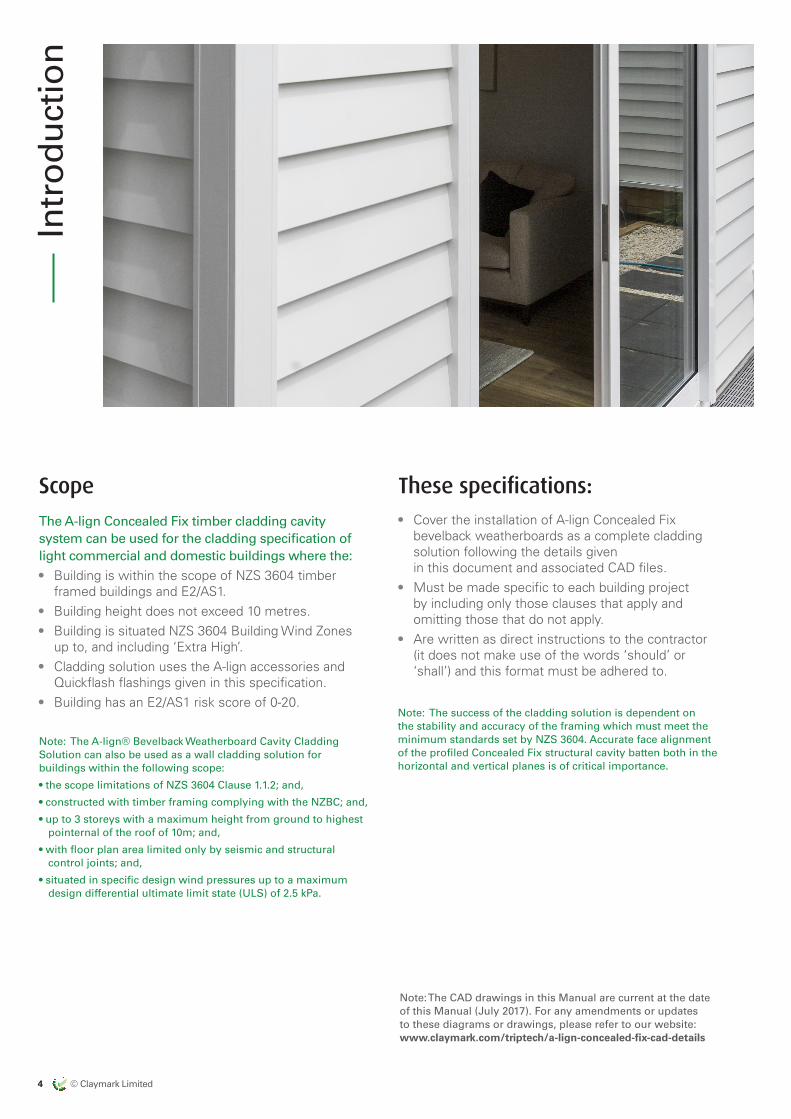
Scope
The A-lign Concealed Fix timber cladding cavity system can be used for the cladding specification of light commercial and domestic buildings where the:• Building is within the scope of NZS 3604 timber
framed buildings and E2/AS1.• Building height does not exceed 10 metres.• Building is situated NZS 3604 Building Wind Zones
up to, and including ‘Extra High’.• Cladding solution uses the A-lign accessories and
Quickflash flashings given in this specification.• Building has an E2/AS1 risk score of 0-20.
These specifications:• Cover the installation of A-lign Concealed Fix
bevelback weatherboards as a complete cladding solution following the details given in this document and associated CAD files.
• Must be made specific to each building project by including only those clauses that apply and omitting those that do not apply.
• Are written as direct instructions to the contractor (it does not make use of the words ‘should’ or ‘shall’) and this format must be adhered to.
Note: The A-lign® Bevelback Weatherboard Cavity Cladding Solution can also be used as a wall cladding solution for buildings within the following scope:
• the scope limitations of NZS 3604 Clause 1.1.2; and,
• constructed with timber framing complying with the NZBC; and,
• up to 3 storeys with a maximum height from ground to highest pointernal of the roof of 10m; and,
• with floor plan area limited only by seismic and structural control joints; and,
• situated in specific design wind pressures up to a maximum design differential ultimate limit state (ULS) of 2.5 kPa.
Note: The success of the cladding solution is dependent on the stability and accuracy of the framing which must meet the minimum standards set by NZS 3604. Accurate face alignment of the profiled Concealed Fix structural cavity batten both in the horizontal and vertical planes is of critical importance.
© Claymark Limited 5
ALMOND
CLAYMARKRECOMMENDED BRAND APPROACH 14/06/17
EXPORT MARKETS
US
US
US
AUSTRALIA
AUSTRALIA
NZ DOMESTIC
by claymark
Profiles Select
Tru-Pine
by claymark
Solid gold™
by claymark
Centurion™
by claymarkG
by claymark
by claymark
by claymark
Premium Pineby claymark
Specifications for exterior cladding
1.0 Before application of the claddingBefore beginning installation of the A-lign Concealed Fix timber cladding system solution ensure that:
• The framing complies with the requirements of NZS 3604 timber framed buildings.
• The framing is straight and within the tolerances allowed by Table 2.1 Tolerances of NZS 3604.
• The moisture content of the framing timber does not exceed 20%.
• Additional studs are included at internal corners.
• The wall underlay complies with the requirements of Table 23 E2/AS1 and is installed in accordance with Section 5.0-5.4 of this specification.
• Window and meter box openings are framed out to give a 7.5mm minimum clearance between the reveal or window frame and the trimmed opening (5mm minimum finished clearance when window installed).
2.0 A-lign Concealed Fix weatherboard2.1 Bevelback Concealed Fix weatherboard sizes
• 142 x 18mm• 187 x 18mmLengths 6.1m and 7.2m
2.2 A-lign timber accessories Note: A-lign accessories are finger-jointed, treated to H3.1 and primed and undercoated. The A-lign Concealed Fix structural cavity batten is treated but not painted.
• A-lign pre-fabricatedricated 102 x 102mm box corner in 5.4m lengths.
• A-lign pre-cut 36 x 18mm scriber with pencil edge in 5.4m lengths.
• A-lign pre-cut 36 x 36mm internal corner scriber pencil edge in 5.4m lengths.
• A-lign pre-cut 42 x 36mm and 66 x 18mm transition scribers with pencil edge in 5.4m lengths.
• A-lign facing boards – available in 42, 66, 90, 116, 138, 185 x 18mm thickness in 5.4m lengths.
• A-lign bevelback tilting fillets – 42mm wide in 5.4m lengths.
• A-lign Concealed Fix structural cavity batten – 45 x 33mm in 5.4m lengths.
• A-lign Concealed Fix flashing batten – 42 x 14mm in 5.4m lengths.
• A-lign soffit eaves mould – 42 x 18mm in 5.4m lengths.
• A-lign weatherhead and sill mould – 42 x 30mm in 5.4m lengths.
2.3 Accessories by Quickflash Use of Quickflash flashings are an integral part of the A-lign cladding system solution as defined in the CAD drawings. Select the flashings required.
Soakers are not part of the Quickflash range so should be purchased separately.
3.0 DetailingA-lign Concealed Fix bevelback weatherboard CAD details are contained in this document.
4.0 A-lign Concealed Fix on siteArrange for delivery of A-lign Concealed Fix timber weatherboards just prior to being required.
4.1 StorageNote: Correct storage of weatherboards on site is critical.
A-lign Concealed Fix weatherboards, Concealed Fix structural cavity battens and accessories have been machined to fine engineered tolerances from finger-jointed clear wood base material with an equilibrium moisture content of 11% plus or minus 2%. If A-lign Concealed Fix weatherboards, Concealed Fix structural cavity battens and accessories are exposed to moisture before installing, as wood is hygroscopic and primers do not prevent moisture uptake, some dimensional swelling will occur and the ease of the system installation will be impaired. Correct storage of the weatherboards, battens and accessories is critical for ease of installation.
4.2 HandlingDo not tip the weatherboards from a truck. Either use a mechanical lifting device or unload the weatherboards by hand.
Do not drag weatherboards across the ground.
Always carry individual weatherboards with their long section vertical, to avoid excessive bending.
6 © Claymark Limited
ALMOND
CLAYMARKRECOMMENDED BRAND APPROACH 14/06/17
EXPORT MARKETS
US
US
US
AUSTRALIA
AUSTRALIA
NZ DOMESTIC
by claymark
Profiles Select
Tru-Pine
by claymark
Solid gold™
by claymark
Centurion™
by claymarkG
by claymark
by claymark
by claymark
Premium Pineby claymark
5.0 Wall underlays
Note: A wall underlay is any material placed on the framing and behind the cladding to act as a second line of weathering defence.
Note: The selected wall underlay must have a serviceable life of at least 50 years.
Wall underlays include flexible materials, such as Kraft based papers or synthetic underlays, and rigid sheathings such as plywood or fibre cement sheet.
Wall underlays suitable for use with the A-lign Concealed Fix timber cladding system solution are those meeting the requirements of Table 23 of E2/AS1.
5.1 Non-rigid underlaysNote: Specify the actual name/insert specific manufacturer/product of underlay you wish to have installed and select the specific installation instructions.
Non-rigid underlays are suitable for use in NZS 3604 Wind Zones up to, and including ‘Very High’, except attached garages. Refer to E2/AS1 – 5.2.
A wall underlay complying with the requirements of E2/AS1 Table 23 must be installed to the outer face of the wall framing.
Select one option from the following:
• Fire retardant Kraft paper (insert specific manufacturer/product).
• Heavyweight bitumen soaked Kraft paper (insert specific manufacturer/product).
• Absorbent synthetic wall underlay (insert specific manufacturer/product).
• Non-absorbent synthetic wall underlay (insert specific manufacturer/product).
For buildings with other than flush-stopped sheet internal linings or areas of unlined wall, the wall underlay must meet the air-tightness requirement of E2/AS1 Table 23.
Openings for windows, doors and meter boxes must have the opening trimmed with flexible flashing tape compatible with the wall underlay, as required by details in E2/AS1.
5.2 Rigid underlay installationNote: Specify the rigid sheathing material to be used. Proprietary systems shall be installed in accordance with the manufacturer’s instructions. Generic sheathing materials shall be installed in accordance with the instructions below.
Rigid Underlays are required in ‘Extra High’ Wind Zones and specific design wind pressures within the scope of this Manual.
Support all rigid sheet edges with framing.
Fix in accordance with the sheet manufacturer’s instructions.
Use hot-dip galvanised fixings, except in sea spray zones where stainless steel fixings must be used.
Tape all joints using barrier sealing tape as per manufacturer’s instructions.
Fix rigid sheathing in place with sufficient fixings to resist wind loading (the sheathing will be finally held in place by the cladding fixings).
Be overlaid with a flexible wall underlay in accordance with E2/AS1 Table 23.
Rigid underlays are also required to external walls of attached garages that are unlined. Refer to E2/AS1 – 5.2.
5.3 Building underlay installationNote: Select to suit the underlays.
Lay the Kraft-based building paper horizontally across the framing members with a minimum 150mm overlap at all joints.
Run material continuously around internal and external corners – do not join material at corners.
Install taut and ensure that there are no creases in the building paper.
Fix with clips or staples and tape in accordance with the building paper manufacturer’s instructions.
Turn wall underlay into the framing all round windows, doors and meter box openings and tape the ‘V’ cut corners and the full width of the sill trimmer with compatible flexible flashing tape.
Cover the wall from bottom to top plate.
Repair all holes or tears in the building paper before commencing cladding installation. Ensure the building paper has not been exposed to the weather for more than the time allowed by the underlay manufacturer.
For installation under Concealed Fix structural cavity battens, install vertical or horizontal strips of plastic tape at 300mm centres and staple to the framing to prevent bulging where Concealed Fix structural cavity batten spacing exceeds 450mm centres.
Specifications for exterior cladding
© Claymark Limited 7
ALMOND
CLAYMARKRECOMMENDED BRAND APPROACH 14/06/17
EXPORT MARKETS
US
US
US
AUSTRALIA
AUSTRALIA
NZ DOMESTIC
by claymark
Profiles Select
Tru-Pine
by claymark
Solid gold™
by claymark
Centurion™
by claymarkG
by claymark
by claymark
by claymark
Premium Pineby claymark
5.4 Synthetic wall underlay installationLay the synthetic wall underlay horizontally across the framing members with a minimum 150mm overlap at sheet joints.
Run material continuously around internal and external corners – do not join material at corners.
Install taut and ensure that there are no creases in the underlay and use fixings that will resist tearing under wind loads.
Fix with clips or staples and tape in accordance with the synthetic underlay manufacturer’s instructions.
Turn underlay edges into the framing all round windows, doors and meter box openings and tape the ‘V’ cut corners and the full width of the sill trimmer with compatible flexible flashing tape.
Cover the wall from bottom to top plate.
Repair all holes or tears in the underlay before commencing cladding installation.
Ensure the synthetic underlay has not been exposed to the weather for more than the time allowed by the underlay manufacturer.
For installation under Concealed Fix structural cavity battens, install vertical or horizontal strips of plastic tape at 300mm centres stapled to the framing to prevent bulging where Concealed Fix structural cavity batten spacing exceeds 450mm centres.
6.0 Flashings
Note: Flashings as noted on the construction details must be provided and may be made from either sheet steel with a galvanized or zinc/aluminium alloy coating, aluminium, from stainless steel, or UPVC. They may be factory pre-finished if required. Refer to NZS3604 section 4 or E2/AS1 Table 20 for durability requirements.
6.1 SupplyFlashings for use with the A-lign Concealed Fix timber cladding system solution are those manufactured by Quickflash as detailed in the CAD drawings. Where the A-lign Concealed Fix cladding abuts a different cladding use flashings as shown in the A-lign Concealed Fix CAD details.
Aluminium window head flashings are the responsibility of the window supplier.
6.2 MaterialsNote: Select the appropriate material for the environment.
Select the flashing material from:
• 0.55 BMT galvanised sheet steel.• 0.55 BMT zinc/aluminium alloy coated.• 0.55 BMT galvanised sheet steel factory coated.• 0.55 BMT zinc/aluminium alloy coated
factory coated.• 316 grade stainless steel. • 0.9mm powder-coated aluminium for window
head flashings – window head flashing by window supplier.
• UPVC.
6.3 Fabrication and installationFlashings must be machine bent accurately to the detailed profile.
Where necessary, site-cut each flashing to suit each circumstance and form stop-ends where appropriate.
Fix flashings using compatible fixings and ensure that the building underlay is installed as shown in the A-lign Concealed Fix CAD details.
Isolate zinc/aluminium alloy coated steel, galvanised steel and uncoated aluminium flashings from timber treated with copper-based treatments with a layer of kraft paper roof underlay.
7.0 Sealants
Note: Sealants are used to assist with weathering at joints and laps. Sealants must not be relied on for primary weather protection.
7.1 MaterialsSealant suitable for use with the A-lign Concealed Fix timber cladding system solution is a (specify brand/manufacturer) sealant complying with E2/AS1 or a sealant covered by a valid BRANZ Appraisal used in accordance with the manufacturer’s instructions.
8.0 Air seals
Note: Air seals are an essential element of the air barrier component of the cladding solution. They complete the air barrier by sealing between the building underlay and the door and window reveals and meter boxes. The air seal is formed by applying sealant over a backing rod to which the sealant will not bond or by using self-expanding polyurethene foam over a backing rod.
8 © Claymark Limited
ALMOND
CLAYMARKRECOMMENDED BRAND APPROACH 14/06/17
EXPORT MARKETS
US
US
US
AUSTRALIA
AUSTRALIA
NZ DOMESTIC
by claymark
Profiles Select
Tru-Pine
by claymark
Solid gold™
by claymark
Centurion™
by claymarkG
by claymark
by claymark
by claymark
Premium Pineby claymark
8.1 MaterialsBacking rod: Closed cell PEF rod of a diameter to suit the gap.
Air seal: Acrylic latex or modified silicon sealant complying with ISO 11600 used in accordance with the manufacturer’s instructions or low expansion self-expanding polyurethane foam in accordance with the requirements of E2/AS1.
8.2 InstallationInsert the backing rod into the gap between the window reveal/meterbox and the trim framing to the perimeter of the opening. Press in approximately 15mm.
Apply the sealant/expanding foam.
Trim off excess material.
9.0 Drained and vented cavities
Note: For designs following E2/AS1 a drained and vented cavity is required behind bevelback weatherboards when the weathertightness risk score for that building face exceeds 12.
The cavity is formed by fixing A-lign Concealed Fix structural cavity battens over the studs. A-lign Concealed Fix structural cavity battens are to be structurally fixed in accordance with BRANZ Bulletin 475. Vermin proofing, which allows draining and ventilation, must be fitted to the bottom of the cavity.
9.1 DesignThe cavity must be open to the exterior at the bottom of every second storey and across the tops of windows, doors and other penetrations such as meter boxes. Fit Quickflash cavity closures to prevent vermin entry.
9.2 MaterialsConcealed Fix structural cavity battens: A-lign Concealed Fix structural cavity battens – 45 x 33mm are treated to H3.1.
Flashing battens: The A-lign flashing battens are 45 x 14mm, treated to H3.1 and are designed to support internal and external corners and abutting cladding profile flashings so the folded edge of the flashing aligns with the adjacent Concealed Fix structural cavity batten and does not distort the weatherboard line.
Cavity closure: Zinc/aluminium alloy coated steel, aluminium or stainless steel supplied by Quickflash with a minimum ventilation area of 1000mm2 per lineal metre of wall.
9.3 Fixing Concealed Fix structural cavity battens Note: Refers to the fixing of A-lign Concealed Fix structural cavity battens, over wall underlay, to the wall studs. This allows the A-lign Concealed Fix bevelback weatherboard to be fixed directly to the Concealed Fix structural cavity batten.
Set out
• As the batten fixing determines the weatherboard set-out it is critical that the base set-out of the batten is perfectly level and achieves the minimum tolerances from the bottom plate or floor slab and the finished ground level as set out in A-lign Concealed Fix drawings Figure 6.01 or Figure 6.02.
• Window trim set out to ensure a full weatherboard at the head can also be calculated using the A-lign Concealed Fix Set-out guides in this Manual.
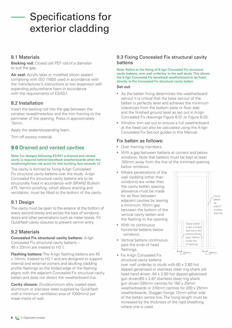
Fix batten as follows:• Over framing members.• With a gap between battens at corners and below
windows. Note that battens must be kept at least 100mm away from the line of the trimmed opening below windows.
• Where penetrations of the wall cladding (other than windows) are wider than the cavity batten spacing, allowance must be made for air flow between adjacent cavities by leaving a minimum 10mm gap between the bottom of the vertical cavity batten and the flashing to the opening.
• With no continuous horizontal battens below windows.
• Vertical battens continuous past the ends of head flashings.
• Fix A-lign Concealed Fix structural cavity battens over wall underlay to studs with 60 x 2.80 hot dipped galvanised or stainless steel ring shank jolt head hand driven. 64 x 2.80 hot dipped galvanised gun driven/65 x 2.87 stainless steel ring shank gun driven 330mm centres for 150 x 25mm weatherboards or 310mm centres for 200 x 25mm weatherboards. Stagger fixings 12mm either side of the batten centre line. The fixing length must be increased by the thickness of the rigid sheathing where one is used.
Specifications for exterior cladding
Cavity batten under window opening to be positioned at least 100mm inside line of opening
Cavity batten up side of window opening
100mm 100mm
© Claymark Limited 9
ALMOND
CLAYMARKRECOMMENDED BRAND APPROACH 14/06/17
EXPORT MARKETS
US
US
US
AUSTRALIA
AUSTRALIA
NZ DOMESTIC
by claymark
Profiles Select
Tru-Pine
by claymark
Solid gold™
by claymark
Centurion™
by claymarkG
by claymark
by claymark
by claymark
Premium Pineby claymark
9.4 Cavity closure Fit continuous Quickflash cavity closure trim to the bottom of all cavities, including across the tops of openings to prevent vermin entry. Fix with 30 x 2.50mm galvanized flat head nails/clouts at 400mm centres.
10.0 Fixing A-lign Concealed Fix bevelback weatherboard
10.1 FixingsUnlike standard A-lign bevelback Weatherboards, no nails are used in fixing the A-lign Concealed Fix bevelback weatherboard system apart from fixing the last board at the eaves, soffit or gable end.
In these isolated positions the nail may need to penetrate the weatherboard and will require punching, spot priming, filling, sanding and re-priming of the area surrounding the nail. If eaves moulds are used then this is fixed through the eaves mould and the weatherboard.
10.2 Fixing methodFix each board on the A-lign Concealed Fix structural cavity batten by sliding the board up to the underside of the lock-grip. Engage it over the machined groove and slowly slide it down the Concealed Fix structural cavity batten until the wedge is engaged.
Do not use a hammer or percussion in this process as percussion can snap the lock-grip off.
Once the weatherboard is locked in position, install the A-lign Concealed Fix EPDM lockstrip by stretching it to reduce its diameter and install in the gap at the top of the weatherboard. Release and trim the EPDM 10mm out from the Concealed Fix structural cavity batten sides.
For long board lengths
Start fixing the board from the centre position and work outwards to the ends repeating the above process.
Shorter board lengths can be engaged over all lock-grips at the same time.
Repeat this process up the wall until the cladding is complete.
10.3 Setting outThe A-lign Concealed Fix structural cavity batten is the storey rod and once fixed in position accurately determines the weatherboard location and the 32mm minimum lap.
All scribers and interior corner moulds are accurately machined to match the Concealed Fix structural cavity battens weatherboard set out.
Remember timber even in its primed form is hygroscopic and will take on moisture and expand when it is exposed to the elements (rain or dampness).
Keeping the product dry at all times prior to installation ensures consistent measurement with minimum variation.
10.4 Fixing procedure for bevelback weatherboardsThe location of the bottom weatherboard is pre-determined by the batten position to achieve minimum clearances between the bottom plate and finished ground levels. Use a A-lign Concealed Fix bevelback weatherboard and a A-lign Concealed Fix base mould. Fix the A-lign Concealed Fix base mould in place.
Continue installing A-lign Concealed Fix weatherboards up the wall.
Cut the final board to fit to the eaves/soffit.
10.5 Joining weatherboardFix weatherboards in full wall lengths where possible.
Make joints where unavoidable over Concealed Fix structural cavity battens. Scarf the jointernal at 45˚ and use one fixing through the overlapping board.
Prime the cut-ends of scarf joints with End Seal aerosol primer, or with two coats of premium timber primer before fixing. Allow to dry between coats.
Cover the jointernal with a flat soaker.
10 © Claymark Limited
ALMOND
CLAYMARKRECOMMENDED BRAND APPROACH 14/06/17
EXPORT MARKETS
US
US
US
AUSTRALIA
AUSTRALIA
NZ DOMESTIC
by claymark
Profiles Select
Tru-Pine
by claymark
Solid gold™
by claymark
Centurion™
by claymarkG
by claymark
by claymark
by claymark
Premium Pineby claymark
10.6 External box corners Fit A-lign pre-fabricatedricated 102 x 102 x 18mm external box corner with a minimum of 50mm cover over the weatherboards and fix with two, 50 x 2.50mm galvanised jolt head nails.
Locate the fixings where the box corner touches the weatherboard at:
• 440mm centres for 142mm weatherboards (4 laps).• 465mm centres for 187mm weatherboards (3 laps).Fit A-lign pre-cut 18mm scriber over the weatherboards, tight against the box corner and fix through pre-drilled holes with 60 x 2.80mm galvanised jolt head nails at 400mm centres.
10.7 External mitred corners Prime the cut-ends of scarf joints with End Seal aerosol primer, or with two coats of premium timber primer before fixing. Allow to dry between coats.
Install either (select one): • A 50 x 50mm Quickflash hemmed angle back
flashing as detailed directly over the Concealed Fix cavity battern.
• Soakers.Join the weatherboards with a tightly fitting 45˚ mitre joint.
10.8 Internal cornersInstall a 65 x 65mm (min 50mm cover) Quickflash hemmed angle back flashing over the Concealed Fix cavity batten.
Scribe and notch alternate weatherboards or use the A-lign pre-cut 36 x 36mm internal corner double scriber.
Prime the cut-ends of scarf joints with End Seal aerosol primer, or with two coats of premium timber primer before fixing. Allow to dry between coats.
11.0 Window and door openings
Note: The integrity of the junctions at the interface of the cladding and the window and door openings is a vital part of the weatherproofing system. Care must be taken to ensure that the work is carried out correctly and that all flashings, weatherings and air seals are in place.
Note: This specification applies to the use of aluminium windows and doors that are in accordance with E2/AS1 paragraph 9.1.10. Use of bi-fold, sliding or other non-hinged windows and doors and timber windows and doors must be submitted to the Building Consent Authority as an Alternative Solution to NZBC Clause E2/AS1.
11.1 Aluminium windows
Aluminium windows installed into a A-lign Con-cealed Fix timber cladding system solution must: • Comply with NZS 4211 for the relevant wind zone
or pressure.• Have a minimum 10mm flange covering the
weatherboard trim.• Incorporate scribers to the flange.• Include a sill tray under window mitres and
mullion junctions. Cavity fix requires window support bars for trim opening wider than 600mm. Refer to E2/AS1 – 9.1.10.5
• Have window trimmed openings constructed as shown in E2/AS1 with flexible flashing tapes and air seals.
• At the pointernal where Bevelback weatherboards overlap, the overall thickness of the two boards is a tight measurement of 32mm. When calculating jamb width, allow plus 34mm and 19mm for the cavity batten.
11.2 Timber windows Note: Timber windows within a weatherboard cladding are not covered by E2/AS1 and must be consented by a BCA as an Alternative Solution.
Timber windows installed into a A-lign Concealed Fix timber cladding system solution must:
• Have profiles in accordance with NZS 3610.• Incorporate facings and scribers.• Incorporate full width sill tray flashings. • Have window trimmed openings constructed
as shown in E2/AS1 with flexible flashing tapes and air seals.
11.3 FlashingsFlashing material and fabrication in accordance with section 6.0 of this specification.
Head flashings must have:
• 10mm stop-ends.• 15˚ cross fall.• 10mm min cover to the window flange.• 50mm min back upstand to give 35mm min
cladding cover.• Fit head flashings to all windows. Stop-ends to
finish at back of cladding. • Sill flashings must have:• 8mm min upstand.
Specifications for exterior cladding
© Claymark Limited 11
ALMOND
CLAYMARKRECOMMENDED BRAND APPROACH 14/06/17
EXPORT MARKETS
US
US
US
AUSTRALIA
AUSTRALIA
NZ DOMESTIC
by claymark
Profiles Select
Tru-Pine
by claymark
Solid gold™
by claymark
Centurion™
by claymarkG
by claymark
by claymark
by claymark
Premium Pineby claymark
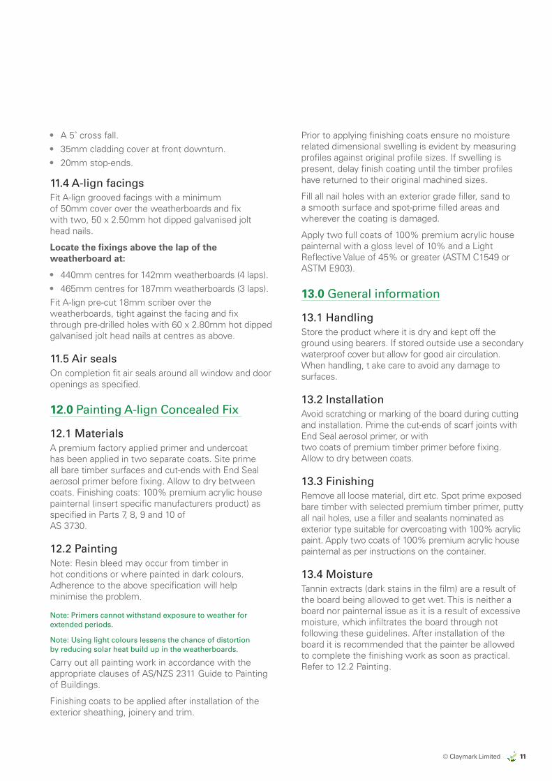
• A 5˚ cross fall.• 35mm cladding cover at front downturn.• 20mm stop-ends.
11.4 A-lign facingsFit A-lign grooved facings with a minimum of 50mm cover over the weatherboards and fix with two, 50 x 2.50mm hot dipped galvanised jolt head nails.
Locate the fixings above the lap of the weatherboard at:
• 440mm centres for 142mm weatherboards (4 laps).• 465mm centres for 187mm weatherboards (3 laps).Fit A-lign pre-cut 18mm scriber over the weatherboards, tight against the facing and fix through pre-drilled holes with 60 x 2.80mm hot dipped galvanised jolt head nails at centres as above.
11.5 Air seals On completion fit air seals around all window and door openings as specified.
12.0 Painting A-lign Concealed Fix
12.1 MaterialsA premium factory applied primer and undercoat has been applied in two separate coats. Site prime all bare timber surfaces and cut-ends with End Seal aerosol primer before fixing. Allow to dry between coats. Finishing coats: 100% premium acrylic house painternal (insert specific manufacturers product) as specified in Parts 7, 8, 9 and 10 of AS 3730.
12.2 Painting Note: Resin bleed may occur from timber in hot conditions or where painted in dark colours. Adherence to the above specification will help minimise the problem.
Note: Primers cannot withstand exposure to weather for extended periods.
Note: Using light colours lessens the chance of distortion by reducing solar heat build up in the weatherboards.
Carry out all painting work in accordance with the appropriate clauses of AS/NZS 2311 Guide to Painting of Buildings.
Finishing coats to be applied after installation of the exterior sheathing, joinery and trim.
Prior to applying finishing coats ensure no moisture related dimensional swelling is evident by measuring profiles against original profile sizes. If swelling is present, delay finish coating until the timber profiles have returned to their original machined sizes.
Fill all nail holes with an exterior grade filler, sand to a smooth surface and spot-prime filled areas and wherever the coating is damaged.
Apply two full coats of 100% premium acrylic house painternal with a gloss level of 10% and a Light Reflective Value of 45% or greater (ASTM C1549 or ASTM E903).
13.0 General information
13.1 HandlingStore the product where it is dry and kept off the ground using bearers. If stored outside use a secondary waterproof cover but allow for good air circulation. When handling, t ake care to avoid any damage to surfaces.
13.2 InstallationAvoid scratching or marking of the board during cutting and installation. Prime the cut-ends of scarf joints with End Seal aerosol primer, or with two coats of premium timber primer before fixing. Allow to dry between coats.
13.3 FinishingRemove all loose material, dirt etc. Spot prime exposed bare timber with selected premium timber primer, putty all nail holes, use a filler and sealants nominated as exterior type suitable for overcoating with 100% acrylic paint. Apply two coats of 100% premium acrylic house painternal as per instructions on the container.
13.4 MoistureTannin extracts (dark stains in the film) are a result of the board being allowed to get wet. This is neither a board nor painternal issue as it is a result of excessive moisture, which infiltrates the board through not following these guidelines. After installation of the board it is recommended that the painter be allowed to complete the finishing work as soon as practical. Refer to 12.2 Painting.
12 © Claymark Limited
ALMOND
CLAYMARKRECOMMENDED BRAND APPROACH 14/06/17
EXPORT MARKETS
US
US
US
AUSTRALIA
AUSTRALIA
NZ DOMESTIC
by claymark
Profiles Select
Tru-Pine
by claymark
Solid gold™
by claymark
Centurion™
by claymarkG
by claymark
by claymark
by claymark
Premium Pineby claymark
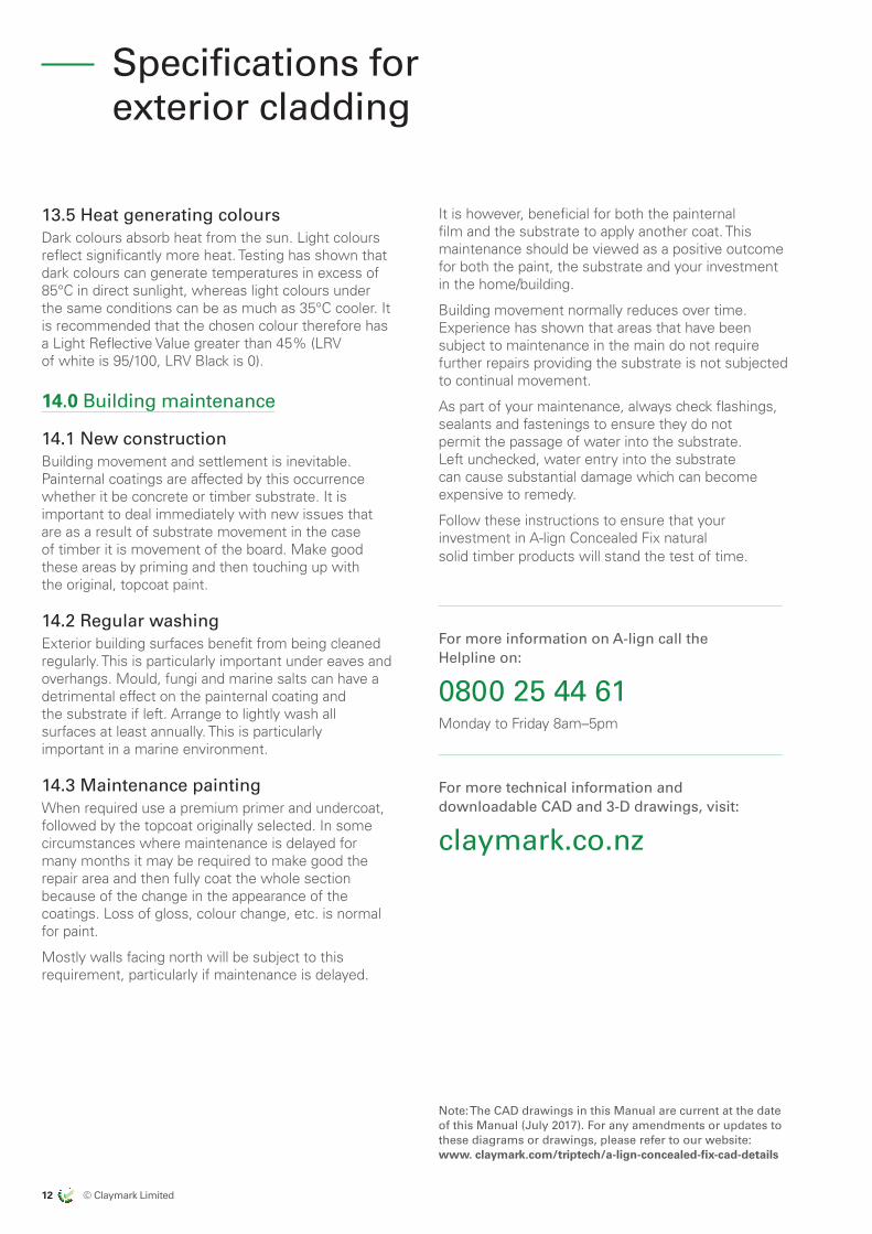
13.5 Heat generating coloursDark colours absorb heat from the sun. Light colours reflect significantly more heat. Testing has shown that dark colours can generate temperatures in excess of 85°C in direct sunlight, whereas light colours under the same conditions can be as much as 35°C cooler. It is recommended that the chosen colour therefore has a Light Reflective Value greater than 45% (LRV of white is 95/100, LRV Black is 0).
14.0 Building maintenance
14.1 New constructionBuilding movement and settlement is inevitable. Painternal coatings are affected by this occurrence whether it be concrete or timber substrate. It is important to deal immediately with new issues that are as a result of substrate movement in the case of timber it is movement of the board. Make good these areas by priming and then touching up with the original, topcoat paint.
14.2 Regular washingExterior building surfaces benefit from being cleaned regularly. This is particularly important under eaves and overhangs. Mould, fungi and marine salts can have a detrimental effect on the painternal coating and the substrate if left. Arrange to lightly wash all surfaces at least annually. This is particularly important in a marine environment.
14.3 Maintenance paintingWhen required use a premium primer and undercoat, followed by the topcoat originally selected. In some circumstances where maintenance is delayed for many months it may be required to make good the repair area and then fully coat the whole section because of the change in the appearance of the coatings. Loss of gloss, colour change, etc. is normal for paint.
Mostly walls facing north will be subject to this requirement, particularly if maintenance is delayed.
It is however, beneficial for both the painternal film and the substrate to apply another coat. This maintenance should be viewed as a positive outcome for both the paint, the substrate and your investment in the home/building.
Building movement normally reduces over time. Experience has shown that areas that have been subject to maintenance in the main do not require further repairs providing the substrate is not subjected to continual movement.
As part of your maintenance, always check flashings, sealants and fastenings to ensure they do not permit the passage of water into the substrate. Left unchecked, water entry into the substrate can cause substantial damage which can become expensive to remedy.
Follow these instructions to ensure that your investment in A-lign Concealed Fix natural solid timber products will stand the test of time.
For more information on A-lign call the Helpline on:
0800 25 44 61 Monday to Friday 8am–5pm
For more technical information and downloadable CAD and 3-D drawings, visit:
claymark.co.nz
Specifications for exterior cladding
Note: The CAD drawings in this Manual are current at the date of this Manual (July 2017). For any amendments or updates to these diagrams or drawings, please refer to our website: www. claymark.com/triptech/a-lign-concealed-fix-cad-details
© Claymark Limited 13
ALMOND
CLAYMARKRECOMMENDED BRAND APPROACH 14/06/17
EXPORT MARKETS
US
US
US
AUSTRALIA
AUSTRALIA
NZ DOMESTIC
by claymark
Profiles Select
Tru-Pine
by claymark
Solid gold™
by claymark
Centurion™
by claymarkG
by claymark
by claymark
by claymark
Premium Pineby claymark
WarrantyClaymark Limited (‘Claymark Ltd’) warrants for a period of 15 years from the date of purchase that it’s A-lign Concealed Fix cladding and A-lign Concealed Fix accessories (The ‘Products’), will be free from production defects, and subject to compliance with the conditions below, will be resistant to cracking, rotting, and damage from borer attacks to the extent set out in Claymark Ltd.’s product literature current at the time of installation.
The A-lign Concealed Fix Technical Manual sets out the approved and recommended methods for cladding installation. A copy of the A-lign Concealed Fix Technical Manual is available from Claymark Ltd, phone toll free on: 0800 25 44 61, Monday to Friday 8am–5pm.
Conditions of Warranty The warranty is strictly subject to the following conditions:
(a) The Products must be installed by a competent and qualified builder, strictly in accordance with the A-lign Concealed Fix Technical Manual current at the time of installation, utilising A-lign Concealed Fix components or products specified in the A-lign Concealed Fix Technical Manual. Where the A-lign Concealed Fix Technical Manual does not provide a suitable detail for installation of The Products then installation must be in accordance with best trade practice determined in consultation with the Territorial Authority and designer of the building works. Further, all other products, including coating and jointing systems, applied to or used in conjunction with The Products must be applied or installed strictly in accordance with the relevant manufacturer’s instructions and best trade practice.
(b) Claymark Ltd will not be liable under this warranty unless a written claim is notified to Claymark Ltd within 30 days of the defect becoming reasonably apparent.
(c) This warranty is for the benefit of the original owner of the building where the A-lign Concealed Fix cladding has been installed. This warranty is not transferable to subsequent owners of the building.
(d) The Products must be maintained strictly in accordance with the A-lign Concealed Fix Technical Manual. Further, all other products, including coating and jointing systems, applied to or used in conjunction with The Products must be maintained strictly in accordance with the relevant manufacturer’s instructions and best trade practice.
(e) The building works in which The Product has been incorporated must be designed and constructed in strict compliance with all relevant provisions of the current New Zealand Building Code (‘NZBC’), regulations and standards, and the Building Consent relating to the building works.
(f) The customer’s sole remedy under this warranty is (at Claymark Ltd’s option) that Claymark Ltd will either supply replacement Products, rectify the affected Products or pay for the cost of the replacement or rectification of the affected Products.
(g) Claymark Ltd will not be liable for any losses or damages (whether direct or indirect) including property damage, personal injury, consequential loss, economic loss or loss of profits, arising in contract or negligence or howsoever arising. Without limiting the foregoing, Claymark Ltd will not be liable for any claims, damages or defects arising from or in any way attributable to poor workmanship, poor design or detailing, settlement or structural movement and/or movement of materials to which The Products are attached, incorrect design of the structure, acts of God including but not limited to earthquakes, cyclones, floods or other severe weather conditions or unusual climatic conditions, efflorescence or performance of paint/coatings applied to The Products, normal wear and tear, growth of mould, mildew, fungi, bacteria, or any organism on the surface of any Products (whether on the exposed or unexposed surfaces).
(h) All warranties, conditions, liabilities and obligations other than those specified in this warranty are excluded to the fullest extent permitted by law. This warranty does not exclude or modify any legal rights a customer may have under the Consumer Guarantees Act 1993. Unless otherwise specified in writing at the time of sale, Claymark Ltd assumes no liability for The Products being fit for any particular purpose under the Building Act 2004, other legislation or at common law.
(i) If any remedial work undertaken under this warranty involves re-coating of The Products, the customer acknowledges and agrees that there may be slight colour differences between the original and replacement Products due to the effects of weathering and variations in materials over time.
A-lign Warranty
14 © Claymark Limited
ALMOND
CLAYMARKRECOMMENDED BRAND APPROACH 14/06/17
EXPORT MARKETS
US
US
US
AUSTRALIA
AUSTRALIA
NZ DOMESTIC
by claymark
Profiles Select
Tru-Pine
by claymark
Solid gold™
by claymark
Centurion™
by claymarkG
by claymark
by claymark
by claymark
Premium Pineby claymark
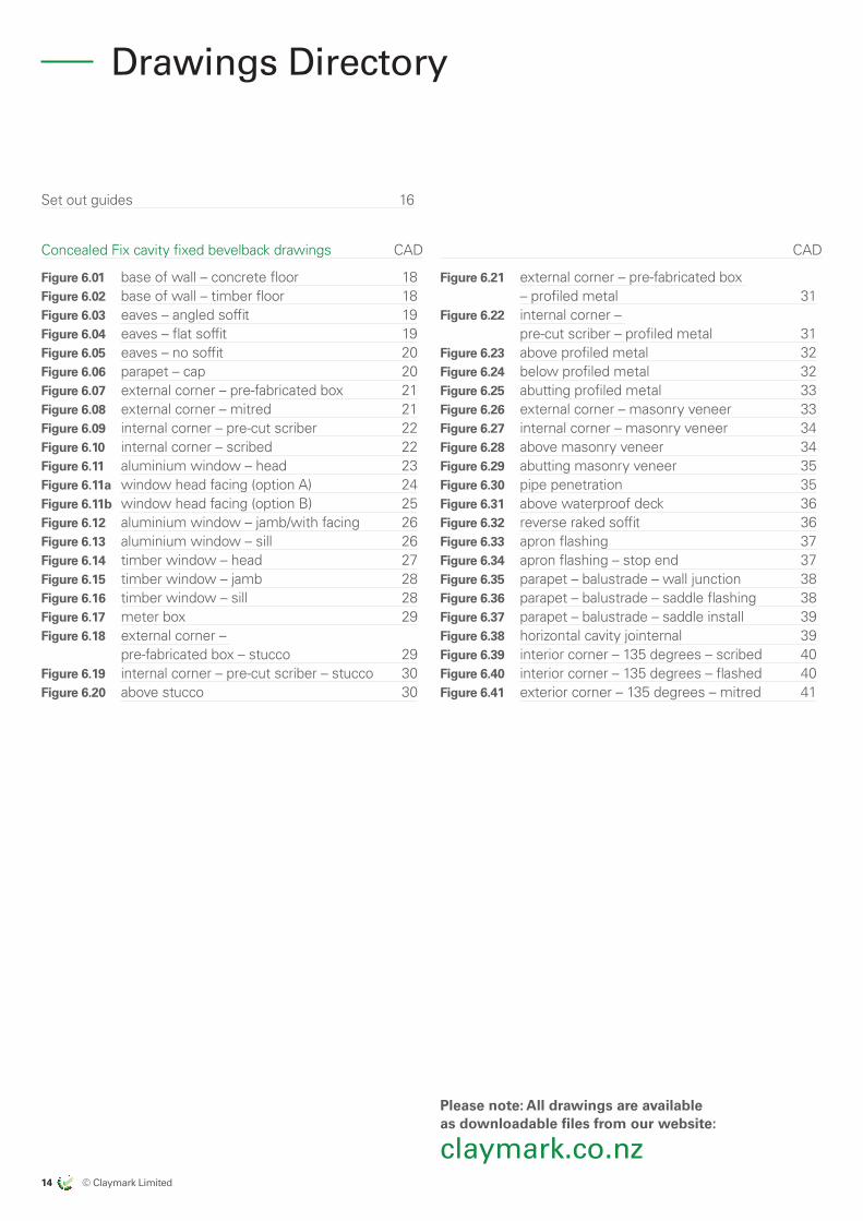
Drawings Directory
Set out guides 16
Concealed Fix cavity fixed bevelback drawings CAD
Figure 6.01 base of wall – concrete floor 18Figure 6.02 base of wall – timber floor 18Figure 6.03 eaves – angled soffit 19Figure 6.04 eaves – flat soffit 19Figure 6.05 eaves – no soffit 20Figure 6.06 parapet – cap 20Figure 6.07 external corner – pre-fabricated box 21Figure 6.08 external corner – mitred 21Figure 6.09 internal corner – pre-cut scriber 22Figure 6.10 internal corner – scribed 22Figure 6.11 aluminium window – head 23Figure 6.11a window head facing (option A) 24Figure 6.11b window head facing (option B) 25Figure 6.12 aluminium window – jamb/with facing 26Figure 6.13 aluminium window – sill 26Figure 6.14 timber window – head 27Figure 6.15 timber window – jamb 28Figure 6.16 timber window – sill 28Figure 6.17 meter box 29Figure 6.18 external corner –
pre-fabricated box – stucco 29Figure 6.19 internal corner – pre-cut scriber – stucco 30Figure 6.20 above stucco 30
CAD
Figure 6.21 external corner – pre-fabricated box – profiled metal 31
Figure 6.22 internal corner – pre-cut scriber – profiled metal 31
Figure 6.23 above profiled metal 32Figure 6.24 below profiled metal 32Figure 6.25 abutting profiled metal 33Figure 6.26 external corner – masonry veneer 33Figure 6.27 internal corner – masonry veneer 34Figure 6.28 above masonry veneer 34Figure 6.29 abutting masonry veneer 35Figure 6.30 pipe penetration 35Figure 6.31 above waterproof deck 36Figure 6.32 reverse raked soffit 36Figure 6.33 apron flashing 37Figure 6.34 apron flashing – stop end 37Figure 6.35 parapet – balustrade – wall junction 38Figure 6.36 parapet – balustrade – saddle flashing 38Figure 6.37 parapet – balustrade – saddle install 39Figure 6.38 horizontal cavity jointernal 39Figure 6.39 interior corner – 135 degrees – scribed 40Figure 6.40 interior corner – 135 degrees – flashed 40Figure 6.41 exterior corner – 135 degrees – mitred 41
Please note: All drawings are available as downloadable files from our website:
claymark.co.nz
© Claymark Limited 15
ALMOND
CLAYMARKRECOMMENDED BRAND APPROACH 14/06/17
EXPORT MARKETS
US
US
US
AUSTRALIA
AUSTRALIA
NZ DOMESTIC
by claymark
Profiles Select
Tru-Pine
by claymark
Solid gold™
by claymark
Centurion™
by claymarkG
by claymark
by claymark
by claymark
Premium Pineby claymark
16 © Claymark Limited
ALMOND
CLAYMARKRECOMMENDED BRAND APPROACH 14/06/17
EXPORT MARKETS
US
US
US
AUSTRALIA
AUSTRALIA
NZ DOMESTIC
by claymark
Profiles Select
Tru-Pine
by claymark
Solid gold™
by claymark
Centurion™
by claymarkG
by claymark
by claymark
by claymark
Premium Pineby claymark
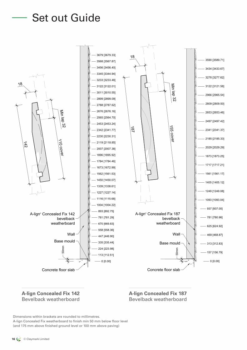
A-lign Concealed Fix 187 Bevelback weatherboard
A-lign Concealed Fix 142 Bevelback weatherboard
Dimensions within brackets are rounded to millimetres. A-lign Concealed Fix weatherboard to finish min 50 mm below floor level (and 175 mm above finished ground level or 100 mm above paving)
Set out Guide
Concrete floor slab
A-lign® Concealed Fix 142bevelback
weatherboard
Wall
Base mould
0 [0.00]
113 [112.51]
224 [223.98]
335 [335.44]
447 [446.90]
558 [558.36]
670 [669.83]
781 [781.29]
893 [892.75]
1004 [1004.22]
1116 [1115.68]
1227 [1227.14]
1339 [1338.61]
1450 [1450.07]
1562 [1561.53]
1673 [1672.99]
1784 [1784.46]
1896 [1895.92]
2007 [2007.38]
2119 [2118.85]
2230 [2230.31]
2342 [2341.77]
2453 [2453.24]
2565 [2564.70]
2676 [2676.16]
2788 [2787.62]
2899 [2899.09]
3011 [3010.55]
3122 [3122.01]
3233 [3233.48]
3345 [3344.94]
3456 [3456.40]
3568 [3567.87]
3679 [3679.33]
50m
m
A-lign® Concealed Fix 187bevelback
weatherboard
Wall
Concrete floor slab
Base mould
50m
m
0 [0.00]
157 [156.79]
313 [312.83]
469 [468.87]
625 [624.92]
781 [780.96]
937 [937.00]
1093 [1093.04]
1249 [1249.08]
1405 [1405.12]
1561 [1561.17]
1717 [1717.21]
1873 [1873.25]
2029 [2029.29]
2185 [2185.33]
2341 [2341.37]
2497 [2497.42]
2653 [2653.46]
2809 [2809.50]
2966 [2965.54]
3122 [3121.58]
3278 [3277.62]
3434 [3433.67]
3590 [3589.71]
187
18
155 coverM
in lap 32
110 cover
142
18
Min lap 32
All Dimensions are to be site checkedbefore construction and installation
Jenkin A-lign® Details
July 17
Issued
Concealed Fix Bevelback weatherboard
bevel_setout_cf
20 July 2017Scale at A4, 1:20 1:2
Set-out Guides Version: 1.5
Note· Dimensions within brackets are rounded to millimetres· A-lign® Concealed Fix weatherboard to finish min 50 mm below floor level (and 175 mm above finished ground
level or 100 mm above paving)
A-lign® Concealed Fix 142bevelback weatherboard
A-lign® Concealed Fix 187bevelback weatherboard
© Claymark Limited 17
ALMOND
CLAYMARKRECOMMENDED BRAND APPROACH 14/06/17
EXPORT MARKETS
US
US
US
AUSTRALIA
AUSTRALIA
NZ DOMESTIC
by claymark
Profiles Select
Tru-Pine
by claymark
Solid gold™
by claymark
Centurion™
by claymarkG
by claymark
by claymark
by claymark
Premium Pineby claymark
CA
D d
raw
ing
s –
cavi
ty fi
xed
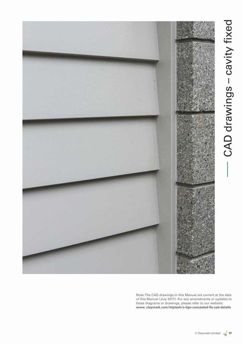
Note: The CAD drawings in this Manual are current at the date of this Manual (July 2017). For any amendments or updates to these diagrams or drawings, please refer to our website: www. claymark.com/triptech/a-lign-concealed-fix-cad-details
18 © Claymark Limited
ALMOND
CLAYMARKRECOMMENDED BRAND APPROACH 14/06/17
EXPORT MARKETS
US
US
US
AUSTRALIA
AUSTRALIA
NZ DOMESTIC
by claymark
Profiles Select
Tru-Pine
by claymark
Solid gold™
by claymark
Centurion™
by claymarkG
by claymark
by claymark
by claymark
Premium Pineby claymark
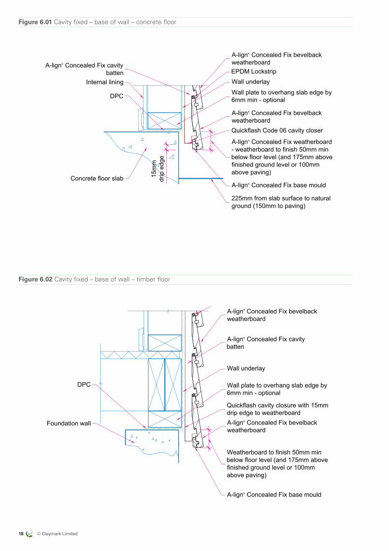
A-lign® Concealed Fix bevelbackweatherboard
DPC
Wall underlayWall plate to overhang slab edge by6mm min - optional
A-lign® Concealed Fix weatherboard- weatherboard to finish 50mm minbelow floor level (and 175mm abovefinished ground level or 100mmabove paving)
Concrete floor slab 15m
mdr
ip e
dge
Quickflash Code 06 cavity closer
A-lign® Concealed Fix bevelbackweatherboard
225mm from slab surface to naturalground (150mm to paving)
A-lign® Concealed Fix cavitybatten
Internal liningEPDM Lockstrip
A-lign® Concealed Fix base mould
All Dimensions are tobe site checkedbefore constructionand installation
Claymark Align® Concealed Fix Details
Concealed Fix bevelback weatherboard - cavity - base of wall - concrete floor
fig6-01_cv_b_wal_con_flr.dwg 19 July 2017Scale at A4 1:5
Version 2.0
Fig 6-01
A-lign® Concealed Fix bevelbackweatherboard
Wall underlay
Wall plate to overhang slab edge by6mm min - optional
Weatherboard to finish 50mm minbelow floor level (and 175mm abovefinished ground level or 100mmabove paving)
DPC
Foundation wall
Quickflash cavity closure with 15mmdrip edge to weatherboard
A-lign® Concealed Fix cavitybatten
A-lign® Concealed Fix bevelbackweatherboard
EPDM Lockstrip
A-lign® Concealed Fix base mould
All Dimensions are tobe site checkedbefore constructionand installation
Claymark Align® Concealed Fix Details
Concealed Fix bevelback weatherboard - cavity - base of wall - timber floor
fig6-02_cv_b_wal_tim_flr.dwg 19 July 2017Scale at A4 1:5
Version 2.0
Fig 6-02
Figure 6.01 Cavity fixed – base of wall – concrete floor
Figure 6.02 Cavity fixed – base of wall – timber floor
© Claymark Limited 19
ALMOND
CLAYMARKRECOMMENDED BRAND APPROACH 14/06/17
EXPORT MARKETS
US
US
US
AUSTRALIA
AUSTRALIA
NZ DOMESTIC
by claymark
Profiles Select
Tru-Pine
by claymark
Solid gold™
by claymark
Centurion™
by claymarkG
by claymark
by claymark
by claymark
Premium Pineby claymark
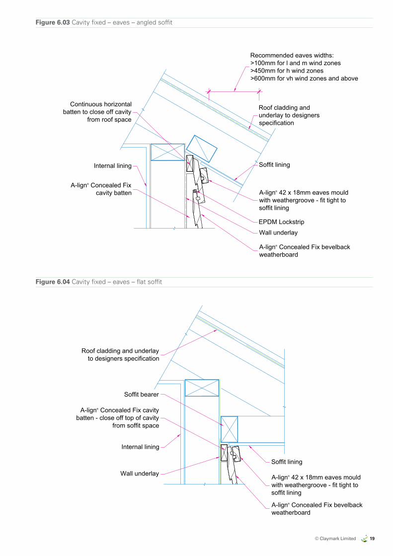
A-lign® Concealed Fix bevelbackweatherboard
Internal lining
A-lign® 42 x 18mm eaves mouldwith weathergroove - fit tight tosoffit lining
Wall underlay
A-lign® Concealed Fixcavity batten
Soffit lining
Roof cladding andunderlay to designersspecification
Continuous horizontalbatten to close off cavity
from roof space
Recommended eaves widths:>100mm for l and m wind zones>450mm for h wind zones>600mm for vh wind zones and above
EPDM Lockstrip
All Dimensions are tobe site checkedbefore constructionand installation
Claymark Align® Concealed Fix Details
Concealed Fix bevelback weatherboard - cavity - eaves - angled soffit
fig6-03_cv_eav_ang_sof.dwg 19 July 2017Scale at A4 1:5
Version 2.0
Fig 6-03
A-lign® Concealed Fix bevelbackweatherboard
Wall underlay A-lign® 42 x 18mm eaves mouldwith weathergroove - fit tight tosoffit lining
Soffit lining
Internal lining
Soffit bearer
A-lign® Concealed Fix cavitybatten - close off top of cavity
from soffit space
Roof cladding and underlayto designers specification
All Dimensions are tobe site checkedbefore constructionand installation
Claymark Align® Concealed Fix Details
Concealed Fix bevelback weatherboard - cavity - eaves - flat soffit
fig6-04_cv_eav_flt_sof.dwg 19 July 2017Scale at A4 1:5
Version 2.0
Fig 6-04
Figure 6.03 Cavity fixed – eaves – angled soffit
Figure 6.04 Cavity fixed – eaves – flat soffit
20 © Claymark Limited
ALMOND
CLAYMARKRECOMMENDED BRAND APPROACH 14/06/17
EXPORT MARKETS
US
US
US
AUSTRALIA
AUSTRALIA
NZ DOMESTIC
by claymark
Profiles Select
Tru-Pine
by claymark
Solid gold™
by claymark
Centurion™
by claymarkG
by claymark
by claymark
by claymark
Premium Pineby claymark
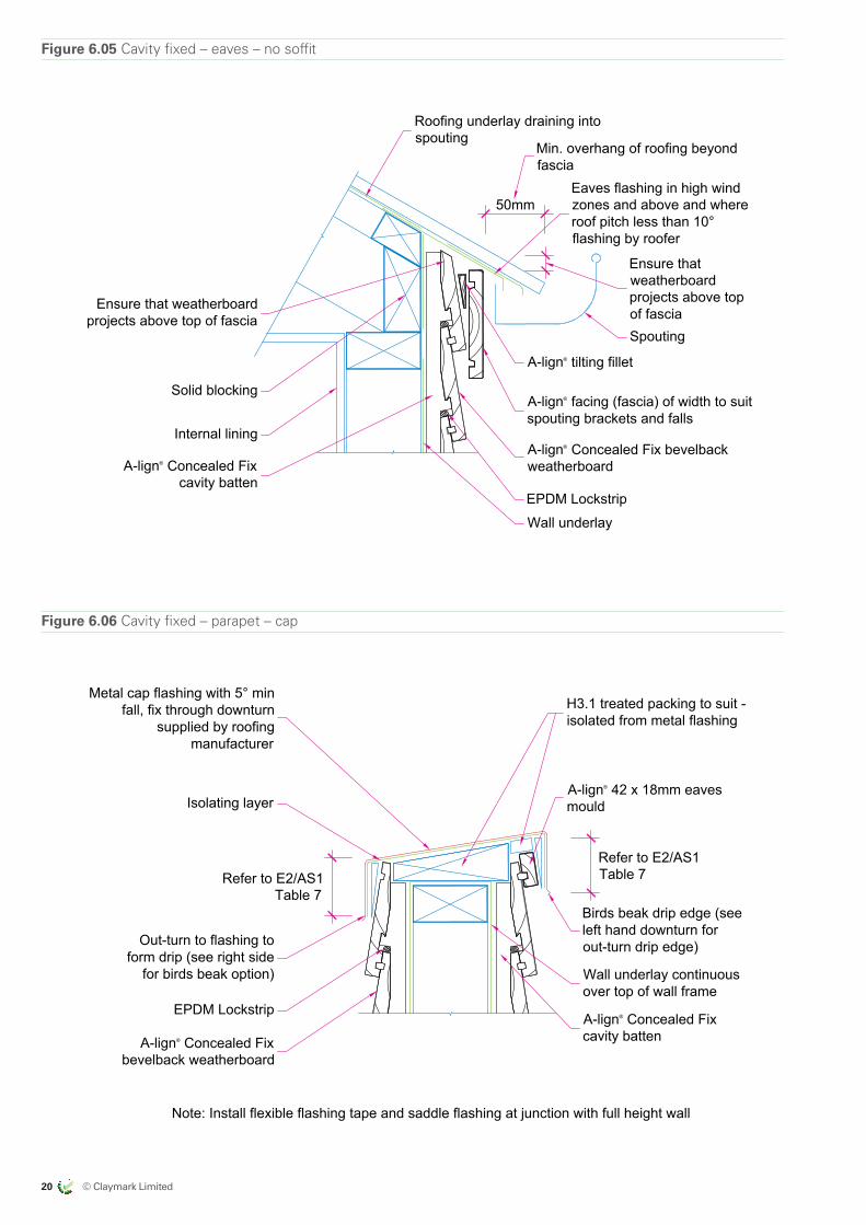
Figure 6.05 Cavity fixed – eaves – no soffit
EPDM Lockstrip
Eaves flashing in high windzones and above and whereroof pitch less than 10°flashing by roofer
A-lign® Concealed Fix bevelbackweatherboard
A-lign® facing (fascia) of width to suitspouting brackets and falls
Spouting
Ensure that weatherboardprojects above top of fascia
Min. overhang of roofing beyondfascia
Roofing underlay draining intospouting
Internal lining
A-lign® tilting fillet
50mm
Solid blocking
A-lign® Concealed Fixcavity batten
Ensure thatweatherboardprojects above topof fascia
Wall underlay
All Dimensions are tobe site checkedbefore constructionand installation
Claymark Align® Concealed Fix Details
Concealed Fix bevelback weatherboard - cavity - eaves - no soffit
fig6-05_cv_eav_no_sof.dwg 19 July 2017Scale at A4 1:5
Version 2.0
Fig 6-05
Figure 6.06 Cavity fixed – parapet – cap
Note: Install flexible flashing tape and saddle flashing at junction with full height wall
Wall underlay continuousover top of wall frame
Isolating layer
Birds beak drip edge (seeleft hand downturn forout-turn drip edge)
H3.1 treated packing to suit -isolated from metal flashing
Metal cap flashing with 5° minfall, fix through downturn
supplied by roofingmanufacturer
Out-turn to flashing toform drip (see right side
for birds beak option)
A-lign® Concealed Fixbevelback weatherboard
A-lign® Concealed Fixcavity batten
A-lign® 42 x 18mm eavesmould
EPDM Lockstrip
Refer to E2/AS1Table 7
Refer to E2/AS1Table 7
All Dimensions are tobe site checkedbefore constructionand installation
Claymark Align® Concealed Fix Details
Concealed Fix bevelback weatherboard - cavity - parapet - cap
fig6-06_cv_parapet_cap.dwg 19 July 2017Scale at A4 1:5
Version 2.0
Fig 6-06
© Claymark Limited 21
ALMOND
CLAYMARKRECOMMENDED BRAND APPROACH 14/06/17
EXPORT MARKETS
US
US
US
AUSTRALIA
AUSTRALIA
NZ DOMESTIC
by claymark
Profiles Select
Tru-Pine
by claymark
Solid gold™
by claymark
Centurion™
by claymarkG
by claymark
by claymark
by claymark
Premium Pineby claymark
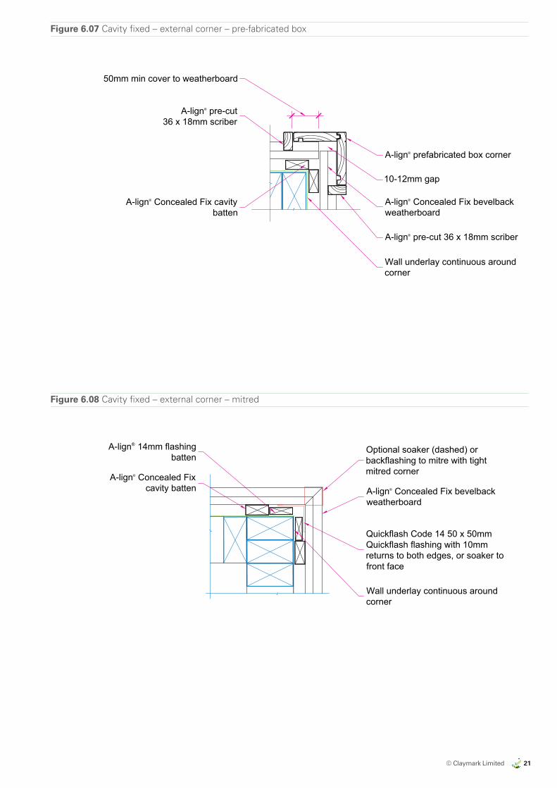
Figure 6.07 Cavity fixed – external corner – pre-fabricated box
A-lign® pre-cut 36 x 18mm scriber
A-lign® pre-cut36 x 18mm scriber
Wall underlay continuous aroundcorner
A-lign® Concealed Fix bevelbackweatherboard
10-12mm gap
A-lign® prefabricated box corner
50mm min cover to weatherboard
A-lign® Concealed Fix cavitybatten
All Dimensions are tobe site checkedbefore constructionand installation
Claymark Align® Concealed Fix Details
Concealed Fix bevelback weatherboard - cavity - external corner - prefab box
fig6-07_cv_ext_box_corner.dwg 19 July 2017Scale at A4 1:5
Version 2.0
Fig 6-07
Figure 6.08 Cavity fixed – external corner – mitred
Optional soaker (dashed) orbackflashing to mitre with tightmitred corner
A-lign® Concealed Fix bevelbackweatherboard
Wall underlay continuous aroundcorner
Quickflash Code 14 50 x 50mmQuickflash flashing with 10mmreturns to both edges, or soaker tofront face
A-lign® 14mm flashingbatten
A-lign® Concealed Fixcavity batten
All Dimensions are tobe site checkedbefore constructionand installation
Claymark Align® Concealed Fix Details
Concealed Fix bevelback weatherboard - cavity - external corner - mitred
fig6-08_cv_ext_corner_mitre.dwg 19 July 2017Scale at A4 1:5
Version 2.0
Fig 6-08
22 © Claymark Limited
ALMOND
CLAYMARKRECOMMENDED BRAND APPROACH 14/06/17
EXPORT MARKETS
US
US
US
AUSTRALIA
AUSTRALIA
NZ DOMESTIC
by claymark
Profiles Select
Tru-Pine
by claymark
Solid gold™
by claymark
Centurion™
by claymarkG
by claymark
by claymark
by claymark
Premium Pineby claymark
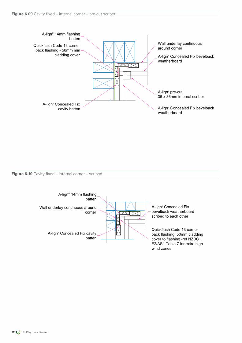
Figure 6.09 Cavity fixed – internal corner – pre-cut scriber
Wall underlay continuousaround cornerQuickflash Code 13 corner
back flashing - 50mm mincladding cover A-lign® Concealed Fix bevelback
weatherboard
A-lign® pre-cut36 x 36mm internal scriber
A-lign® Concealed Fix bevelbackweatherboard
A-lign® Concealed Fixcavity batten
A-lign® 14mm flashingbatten
All Dimensions are tobe site checkedbefore constructionand installation
Claymark Align® Concealed Fix Details
Concealed Fix bevelback weatherboard - cavity - internal corner - pre-cut scriber
fig6-09_cv_int_cnr_scriber.dwg 19 July 2017Scale at A4 1:5
Version 2.0
Fig 6-09
Figure 6.10 Cavity fixed – internal corner – scribed
A-lign® Concealed Fixbevelback weatherboardscribed to each other
Wall underlay continuous aroundcorner
Quickflash Code 13 cornerback flashing, 50mm claddingcover to flashing -ref NZBCE2/AS1 Table 7 for extra highwind zones
A-lign® Concealed Fix cavitybatten
A-lign® 14mm flashingbatten
All Dimensions are tobe site checkedbefore constructionand installation
Claymark Align® Concealed Fix Details
Concealed Fix bevelback weatherboard - cavity - internal corner - scribed
fig6-10_cv_int_corner_scribed.dwg 19 July 2017Scale at A4 1:5
Version 2.0
Fig 6-10
© Claymark Limited 23
ALMOND
CLAYMARKRECOMMENDED BRAND APPROACH 14/06/17
EXPORT MARKETS
US
US
US
AUSTRALIA
AUSTRALIA
NZ DOMESTIC
by claymark
Profiles Select
Tru-Pine
by claymark
Solid gold™
by claymark
Centurion™
by claymarkG
by claymark
by claymark
by claymark
Premium Pineby claymark
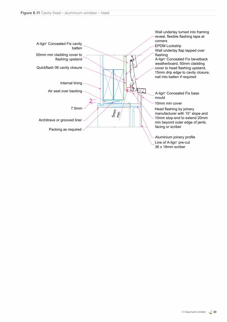
Figure 6.11 Cavity fixed – aluminium window – head
A-lign® Concealed Fix bevelbackweatherboard, 50mm claddingcover to head flashing upstand,15mm drip edge to cavity closure,nail into batten if required
Quickflash 06 cavity closure
Wall underlay turned into framingreveal, flexible flashing tape atcornersEPDM Lockstrip
Head flashing by joinerymanufacturer with 15° slope and10mm stop-end to extend 20mmmin beyond outer edge of jamb,facing or scriber
Aluminium joinery profile
50mm min cladding cover toflashing upstand
Air seal over backing
Architrave or grooved liner
A-lign® Concealed Fix cavitybatten
Line of A-lign® pre-cut36 x 18mm scriber
A-lign® Concealed Fix basemould
Internal lining
7.5mm
Packing as required
5mm
min
10mm min cover
Wall underlay flap lapped overflashing
All Dimensions are tobe site checkedbefore constructionand installation
Claymark Align® Concealed Fix Details
Concealed Fix bevelback weatherboard - cavity - aluminium window - head
fig6-11_cv_alu_wind_head.dwg 19 July 2017Scale at A4 1:5
Version 2.0
Fig 6-11
24 © Claymark Limited
ALMOND
CLAYMARKRECOMMENDED BRAND APPROACH 14/06/17
EXPORT MARKETS
US
US
US
AUSTRALIA
AUSTRALIA
NZ DOMESTIC
by claymark
Profiles Select
Tru-Pine
by claymark
Solid gold™
by claymark
Centurion™
by claymarkG
by claymark
by claymark
by claymark
Premium Pineby claymark
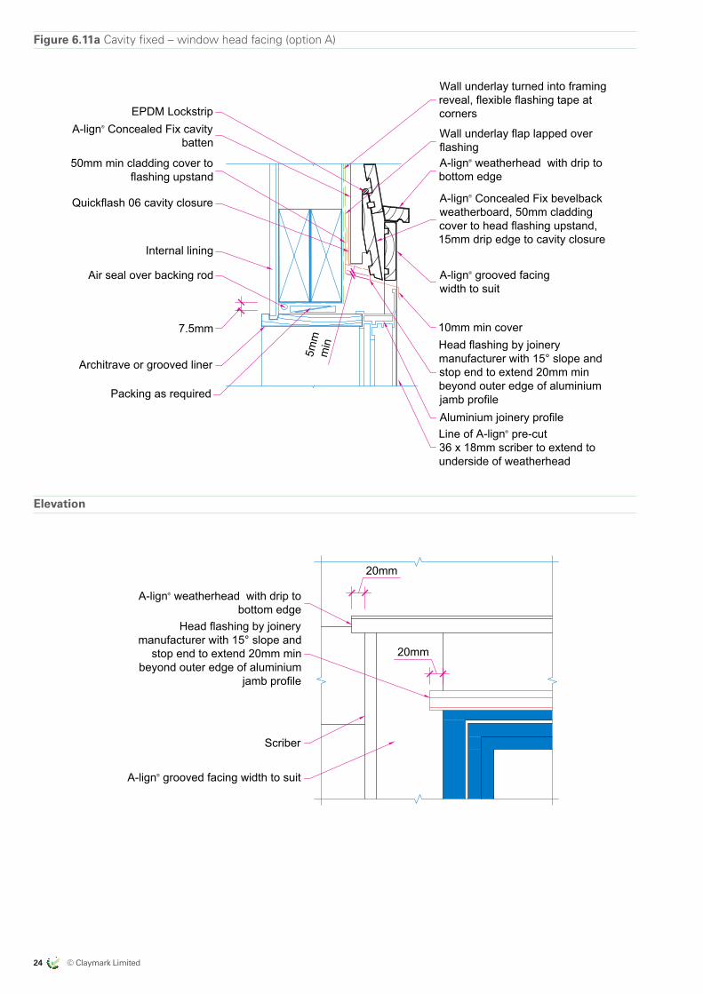
Figure 6.11a Cavity fixed – window head facing (option A)
A-lign® Concealed Fix bevelbackweatherboard, 50mm claddingcover to head flashing upstand,15mm drip edge to cavity closure
Quickflash 06 cavity closure
Wall underlay turned into framingreveal, flexible flashing tape atcorners
Wall underlay flap lapped overflashing
Head flashing by joinerymanufacturer with 15° slope andstop end to extend 20mm minbeyond outer edge of aluminiumjamb profileAluminium joinery profile
50mm min cladding cover toflashing upstand
Air seal over backing rod
Architrave or grooved liner
A-lign® Concealed Fix cavitybatten
Line of A-lign® pre-cut36 x 18mm scriber to extend tounderside of weatherhead
A-lign® weatherhead with drip tobottom edge
Internal lining
7.5mm
Packing as required
5mm
min
10mm min cover
A-lign® grooved facingwidth to suit
EPDM Lockstrip
Elevation
20mm
Scriber
A-lign® weatherhead with drip tobottom edge
Head flashing by joinerymanufacturer with 15° slope and
stop end to extend 20mm minbeyond outer edge of aluminium
jamb profile
A-lign® grooved facing width to suit
20mm
All Dimensions are tobe site checkedbefore constructionand installation
Claymark Align® Concealed Fix Details
Concealed Fix bevelback weatherboard - cavity fixed - window head facing - option A
fig6-11a_cv_alu_wind_head.dwg 19 July 2017Scale at A4 1:5
Version 2.0
Fig 6-11a
Elevation
A-lign® Concealed Fix bevelbackweatherboard, 50mm claddingcover to head flashing upstand,15mm drip edge to cavity closure
Quickflash 06 cavity closure
Wall underlay turned into framingreveal, flexible flashing tape atcorners
Wall underlay flap lapped overflashing
Head flashing by joinerymanufacturer with 15° slope andstop end to extend 20mm minbeyond outer edge of aluminiumjamb profileAluminium joinery profile
50mm min cladding cover toflashing upstand
Air seal over backing rod
Architrave or grooved liner
A-lign® Concealed Fix cavitybatten
Line of A-lign® pre-cut36 x 18mm scriber to extend tounderside of weatherhead
A-lign® weatherhead with drip tobottom edge
Internal lining
7.5mm
Packing as required
5mm
min
10mm min cover
A-lign® grooved facingwidth to suit
EPDM Lockstrip
Elevation
20mm
Scriber
A-lign® weatherhead with drip tobottom edge
Head flashing by joinerymanufacturer with 15° slope and
stop end to extend 20mm minbeyond outer edge of aluminium
jamb profile
A-lign® grooved facing width to suit
20mm
All Dimensions are tobe site checkedbefore constructionand installation
Claymark Align® Concealed Fix Details
Concealed Fix bevelback weatherboard - cavity fixed - window head facing - option A
fig6-11a_cv_alu_wind_head.dwg 19 July 2017Scale at A4 1:5
Version 2.0
Fig 6-11a
© Claymark Limited 25
ALMOND
CLAYMARKRECOMMENDED BRAND APPROACH 14/06/17
EXPORT MARKETS
US
US
US
AUSTRALIA
AUSTRALIA
NZ DOMESTIC
by claymark
Profiles Select
Tru-Pine
by claymark
Solid gold™
by claymark
Centurion™
by claymarkG
by claymark
by claymark
by claymark
Premium Pineby claymark
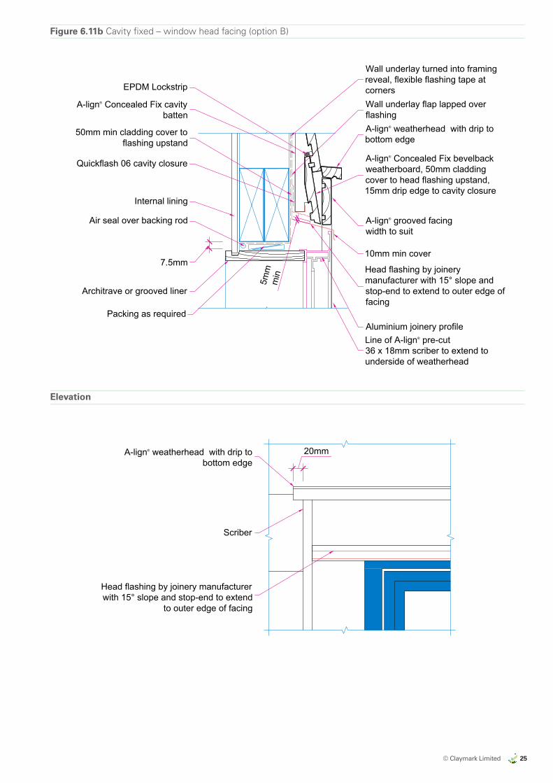
A-lign® Concealed Fix bevelbackweatherboard, 50mm claddingcover to head flashing upstand,15mm drip edge to cavity closure
Quickflash 06 cavity closure
Wall underlay turned into framingreveal, flexible flashing tape atcornersWall underlay flap lapped overflashing
Head flashing by joinerymanufacturer with 15° slope andstop-end to extend to outer edge offacing
Aluminium joinery profile
50mm min cladding cover toflashing upstand
Air seal over backing rod
Architrave or grooved liner
A-lign® Concealed Fix cavitybatten
Line of A-lign® pre-cut36 x 18mm scriber to extend tounderside of weatherhead
A-lign® weatherhead with drip tobottom edge
Internal lining
7.5mm
Packing as required
5mm
min
10mm min cover
A-lign® grooved facingwidth to suit
EPDM Lockstrip
Elevation
Head flashing by joinery manufacturerwith 15° slope and stop-end to extend
to outer edge of facing
A-lign® weatherhead with drip tobottom edge
Scriber
20mm
All Dimensions are tobe site checkedbefore constructionand installation
Claymark Align® Concealed Fix Details
Concealed Fix bevelback weatherboard - cavity fixed - window head facing - option B
fig6-11b_cv_alu_wind_head.dwg 19 July 2017Scale at A4 1:5
Version 2.0
Fig 6-11bFigure 6.11b Cavity fixed – window head facing (option B)
A-lign® Concealed Fix bevelbackweatherboard, 50mm claddingcover to head flashing upstand,15mm drip edge to cavity closure
Quickflash 06 cavity closure
Wall underlay turned into framingreveal, flexible flashing tape atcornersWall underlay flap lapped overflashing
Head flashing by joinerymanufacturer with 15° slope andstop-end to extend to outer edge offacing
Aluminium joinery profile
50mm min cladding cover toflashing upstand
Air seal over backing rod
Architrave or grooved liner
A-lign® Concealed Fix cavitybatten
Line of A-lign® pre-cut36 x 18mm scriber to extend tounderside of weatherhead
A-lign® weatherhead with drip tobottom edge
Internal lining
7.5mm
Packing as required
5mm
min
10mm min cover
A-lign® grooved facingwidth to suit
EPDM Lockstrip
Elevation
Head flashing by joinery manufacturerwith 15° slope and stop-end to extend
to outer edge of facing
A-lign® weatherhead with drip tobottom edge
Scriber
20mm
All Dimensions are tobe site checkedbefore constructionand installation
Claymark Align® Concealed Fix Details
Concealed Fix bevelback weatherboard - cavity fixed - window head facing - option B
fig6-11b_cv_alu_wind_head.dwg 19 July 2017Scale at A4 1:5
Version 2.0
Fig 6-11b
Elevation
26 © Claymark Limited
ALMOND
CLAYMARKRECOMMENDED BRAND APPROACH 14/06/17
EXPORT MARKETS
US
US
US
AUSTRALIA
AUSTRALIA
NZ DOMESTIC
by claymark
Profiles Select
Tru-Pine
by claymark
Solid gold™
by claymark
Centurion™
by claymarkG
by claymark
by claymark
by claymark
Premium Pineby claymark
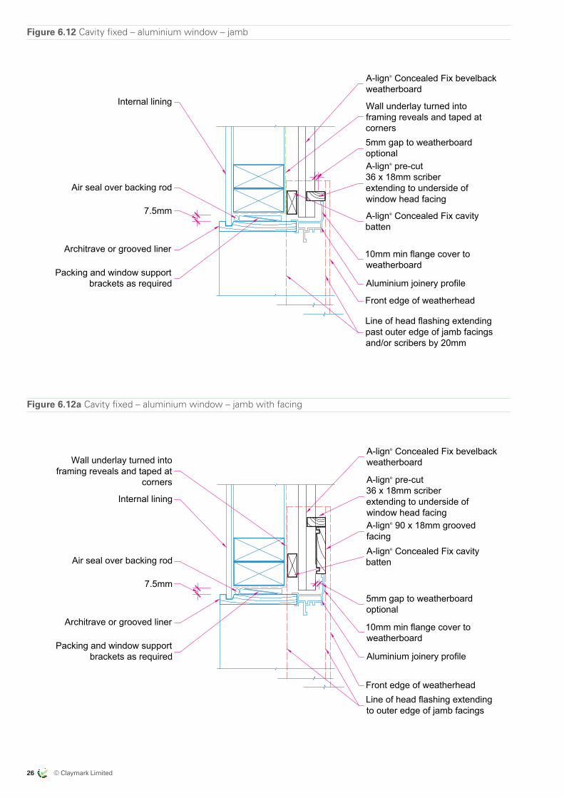
Figure 6.12a Cavity fixed – aluminium window – jamb with facing
Internal lining
A-lign® pre-cut36 x 18mm scriberextending to underside ofwindow head facing
5mm gap to weatherboardoptional
10mm min flange cover toweatherboard
Aluminium joinery profile
Front edge of weatherheadLine of head flashing extendingto outer edge of jamb facings
Air seal over backing rod
Architrave or grooved liner
A-lign® Concealed Fix cavitybatten
7.5mm
A-lign® Concealed Fix bevelbackweatherboardWall underlay turned into
framing reveals and taped atcorners
Packing and window supportbrackets as required
A-lign® 90 x 18mm groovedfacing
All Dimensions are tobe site checkedbefore constructionand installation
Claymark Align® Concealed Fix Details
Concealed Fix bevelback weatherboard - cavity - aluminium window - jamb
fig6-12a_cv_alu_wind_jamb.dwg 19 July 2017Scale at A4 1:5
Version 2.0
Fig 6-12a
Figure 6.12 Cavity fixed – aluminium window – jamb
Internal lining
A-lign® pre-cut36 x 18mm scriberextending to underside ofwindow head facing
5mm gap to weatherboardoptional
10mm min flange cover toweatherboard
Aluminium joinery profile
Front edge of weatherhead
Line of head flashing extendingpast outer edge of jamb facingsand/or scribers by 20mm
Air seal over backing rod
Architrave or grooved liner
A-lign® Concealed Fix cavitybatten
7.5mm
A-lign® Concealed Fix bevelbackweatherboard
Wall underlay turned intoframing reveals and taped atcorners
Packing and window supportbrackets as required
All Dimensions are tobe site checkedbefore constructionand installation
Claymark Align® Concealed Fix Details
Concealed Fix bevelback weatherboard - cavity - aluminium window - jamb
fig6-12_cv_alu_wind_jamb.dwg 19 July 2017Scale at A4 1:5
Version 2.0
Fig 6-12
© Claymark Limited 27
ALMOND
CLAYMARKRECOMMENDED BRAND APPROACH 14/06/17
EXPORT MARKETS
US
US
US
AUSTRALIA
AUSTRALIA
NZ DOMESTIC
by claymark
Profiles Select
Tru-Pine
by claymark
Solid gold™
by claymark
Centurion™
by claymarkG
by claymark
by claymark
by claymark
Premium Pineby claymark
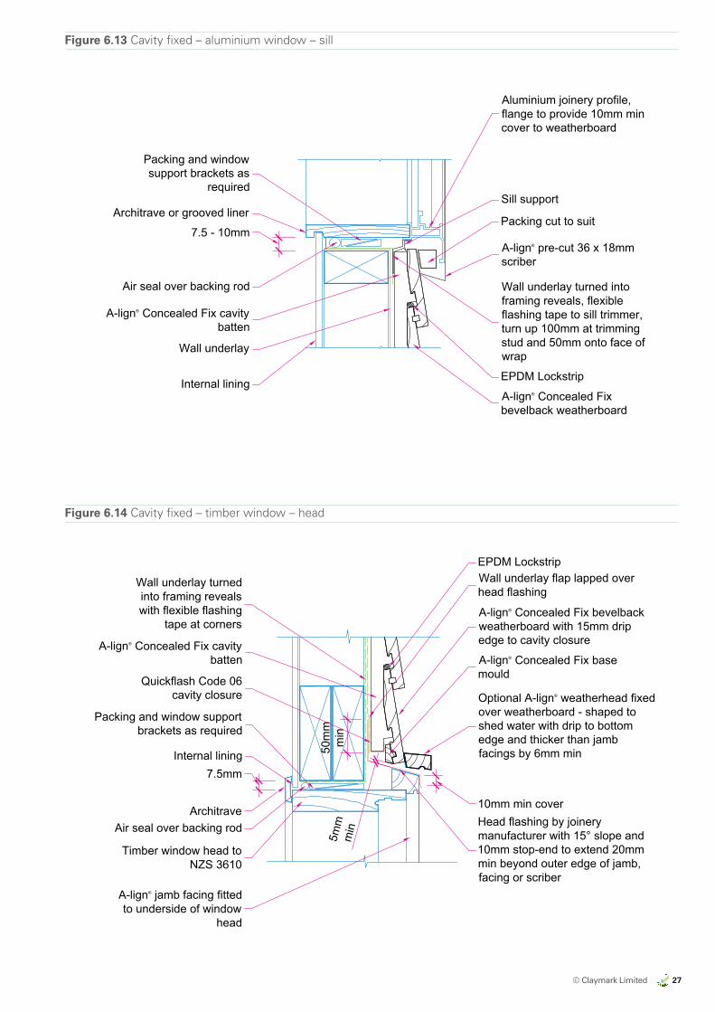
Figure 6.14 Cavity fixed – timber window – head
50m
mm
in
A-lign® Concealed Fix bevelbackweatherboard with 15mm dripedge to cavity closure
Packing and window supportbrackets as required
Wall underlay turnedinto framing revealswith flexible flashing
tape at corners
Wall underlay flap lapped overhead flashing
Optional A-lign® weatherhead fixedover weatherboard - shaped toshed water with drip to bottomedge and thicker than jambfacings by 6mm min
Head flashing by joinerymanufacturer with 15° slope and10mm stop-end to extend 20mmmin beyond outer edge of jamb,facing or scriber
A-lign® jamb facing fittedto underside of window
head
Air seal over backing rodArchitrave
Timber window head toNZS 3610
A-lign® Concealed Fix cavitybatten
Quickflash Code 06cavity closure
7.5mm
10mm min cover
A-lign® Concealed Fix basemould
Internal lining
5mm
min
EPDM Lockstrip
All Dimensions are tobe site checkedbefore constructionand installation
Claymark Align® Concealed Fix Details
Concealed Fix bevelback weatherboard - cavity - timber window - head
fig6-14_cv_tim_wind_head.dwg 19 July 2017Scale at A4 1:5
Version 2.0
Fig 6-14
Figure 6.13 Cavity fixed – aluminium window – sill
Aluminium joinery profile,flange to provide 10mm mincover to weatherboard
Internal liningA-lign® Concealed Fixbevelback weatherboard
Wall underlay turned intoframing reveals, flexibleflashing tape to sill trimmer,turn up 100mm at trimmingstud and 50mm onto face ofwrap
Air seal over backing rod
Architrave or grooved liner
Packing and windowsupport brackets as
required
A-lign® pre-cut 36 x 18mmscriber
A-lign® Concealed Fix cavitybatten
7.5 - 10mm
Wall underlay
Packing cut to suit
EPDM Lockstrip
Sill support
All Dimensions are tobe site checkedbefore constructionand installation
Claymark Align® Concealed Fix Details
Concealed Fix bevelback weatherboard - cavity - aluminium window - sill
fig6-13_cv_alu_wind_sill.dwg 19 July 2017Scale at A4 1:5
Version 2.0
Fig 6-13
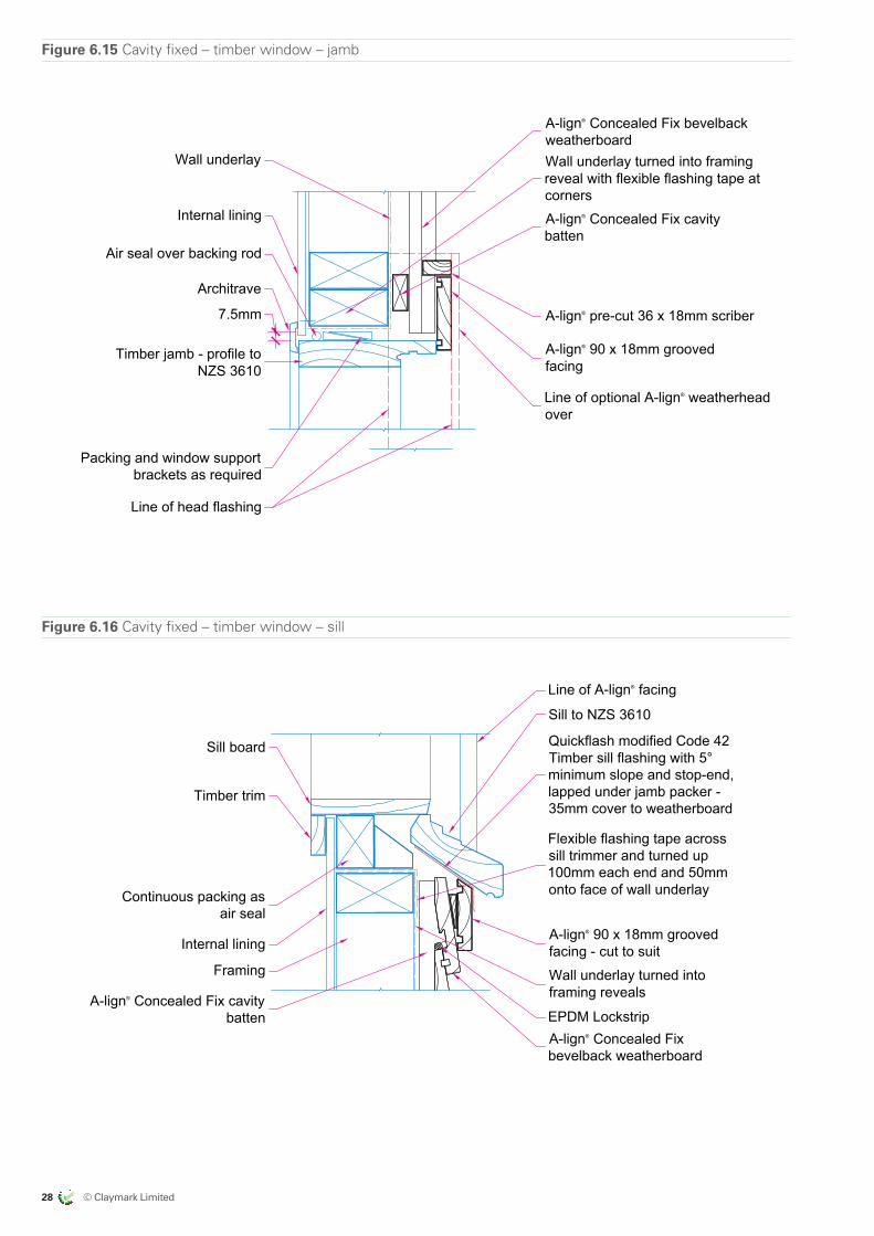
28 © Claymark Limited
ALMOND
CLAYMARKRECOMMENDED BRAND APPROACH 14/06/17
EXPORT MARKETS
US
US
US
AUSTRALIA
AUSTRALIA
NZ DOMESTIC
by claymark
Profiles Select
Tru-Pine
by claymark
Solid gold™
by claymark
Centurion™
by claymarkG
by claymark
by claymark
by claymark
Premium Pineby claymark
Figure 6.15 Cavity fixed – timber window – jamb
A-lign® Concealed Fix bevelbackweatherboard
Internal lining
Wall underlay turned into framingreveal with flexible flashing tape atcorners
A-lign® pre-cut 36 x 18mm scriber
A-lign® 90 x 18mm groovedfacing
Line of optional A-lign® weatherheadover
Line of head flashing
Air seal over backing rod
Architrave
Timber jamb - profile toNZS 3610
A-lign® Concealed Fix cavitybatten
7.5mm
Wall underlay
Packing and window supportbrackets as required
All Dimensions are tobe site checkedbefore constructionand installation
Claymark Align® Concealed Fix Details
Concealed Fix bevelback weatherboard - cavity - timber window - jamb
fig6-15_cv_tim_wind_jamb.dwg 19 July 2017Scale at A4 1:5
Version 2.0
Fig 6-15
Figure 6.16 Cavity fixed – timber window – sill
Line of A-lign® facing
Sill to NZS 3610
Quickflash modified Code 42Timber sill flashing with 5°minimum slope and stop-end,lapped under jamb packer -35mm cover to weatherboard
A-lign® 90 x 18mm groovedfacing - cut to suit
Flexible flashing tape acrosssill trimmer and turned up100mm each end and 50mmonto face of wall underlay
Wall underlay turned intoframing reveals
A-lign® Concealed Fixbevelback weatherboard
Sill board
Timber trim
Continuous packing asair seal
Internal lining
Framing
A-lign® Concealed Fix cavitybatten EPDM Lockstrip
All Dimensions are tobe site checkedbefore constructionand installation
Claymark Align® Concealed Fix Details
Concealed Fix bevelback weatherboard - cavity - timber window - sill
fig6-16_cv_tim_wind_sill.dwg 19 July 2017Scale at A4 1:5
Version 2.0
Fig 6-16

© Claymark Limited 29
ALMOND
CLAYMARKRECOMMENDED BRAND APPROACH 14/06/17
EXPORT MARKETS
US
US
US
AUSTRALIA
AUSTRALIA
NZ DOMESTIC
by claymark
Profiles Select
Tru-Pine
by claymark
Solid gold™
by claymark
Centurion™
by claymarkG
by claymark
by claymark
by claymark
Premium Pineby claymark
Figure 6.17 Cavity fixed – meter box
Note: Jamb detail similar to sill with angle to give cover to weatherboard with a A-lign® pre-cut36 x 18mm scriber
Wall underlay flap, lapped overhead flashing upstand
Optional A-lign® weatherhead fixedover sealant to weatherboard andextending 30mm beyond jambsections each sideForm head flashing with 15°
slope with 10mm stop-endextended to 20mm beyondscriber, 10mm min cover to
flange
5mm gap
5mm clearance
Meter box
Seal and rivet 30 x 30mm angle tometer box all round
Wall underlay turned intoframing reveal, flexible flashing
tape to trimmer and turn up100mm at ends
A-lign® Concealed Fix bevelbackweatherboard
A-lign® Concealed Fix cavitybatten
A-lign® Concealed Fix cavitybatten
50m
m
Quickflash code 06 cavityclosure with 15mm drip edge to
weatherboard
Airseal over backing rod
Airseal over backing rod
Wall underlay
Packing cut to suit
A-lign® Concealed Fix base mould
A-lign® pre-cut 36 x 18mm scriber
EPDM Lockstrip
All Dimensions are tobe site checkedbefore constructionand installation
Claymark Align® Concealed Fix Details
Concealed Fix bevelback weatherboard - cavity - meter box
fig6-17_cv_meter_box.dwg 19 July 2017Scale at A4 1:5
Version 2.0
Fig 6-17
Figure 6.18 Cavity fixed – external corner – pre-fabricated box – stucco
50mm mincover A-lign® prefabricated box corner to
give 50mm min cladding coverA-lign® pre-cut 36 x 18mm
scriber
A-lign® standard cavity batten
Stucco
Backing (non-rigid, or rigid with sliplayer)Wall underlay continuous aroundcorner
A-lign® Concealed Fixbevelback weatherboard
Note: Run wall underlay continuously around internal and external corners - do not joint material atcorners
A-lign® Concealed Fix cavitybatten
All Dimensions are tobe site checkedbefore constructionand installation
Claymark Align® Concealed Fix Details
Concealed Fix bevelback weatherboard - cavity - external corner - prefab box - stucco
fig6-18_cv_ext_box_crn_stuc.dwg 19 July 2017Scale at A4 1:5
Version 2.0
Fig 6-18
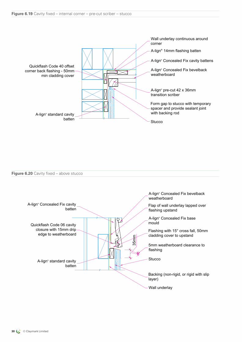
30 © Claymark Limited
ALMOND
CLAYMARKRECOMMENDED BRAND APPROACH 14/06/17
EXPORT MARKETS
US
US
US
AUSTRALIA
AUSTRALIA
NZ DOMESTIC
by claymark
Profiles Select
Tru-Pine
by claymark
Solid gold™
by claymark
Centurion™
by claymarkG
by claymark
by claymark
by claymark
Premium Pineby claymark
Figure 6.19 Cavity fixed – internal corner – pre-cut scriber – stucco
Wall underlay continuous aroundcorner
A-lign® standard cavitybatten
A-lign® Concealed Fix bevelbackweatherboard
Form gap to stucco with temporaryspacer and provide sealant jointwith backing rod
Stucco
Quickflash Code 40 offsetcorner back flashing - 50mm
min cladding cover
A-lign® 14mm flashing batten
A-lign® pre-cut 42 x 36mmtransition scriber
A-lign® Concealed Fix cavity battens
All Dimensions are tobe site checkedbefore constructionand installation
Claymark Align® Concealed Fix Details
Concealed Fix bevelback weatherboard - cavity - internal corner - pre-cut scriber - stucco
fig6-19_cv_int_crn_stuc.dwg 19 July 2017Scale at A4 1:5
Version 2.0
Fig 6-19
Figure 6.20 Cavity fixed – above stucco
A-lign® Concealed Fix bevelbackweatherboard
A-lign® standard cavitybatten
Flap of wall underlay lapped overflashing upstand
Flashing with 15° cross fall, 50mmcladding cover to upstand
5mm weatherboard clearance toflashing
Wall underlay
Stucco
Backing (non-rigid, or rigid with sliplayer)
35m
m
A-lign® Concealed Fix cavitybatten
Quickflash Code 06 cavityclosure with 15mm drip
edge to weatherboard
A-lign® Concealed Fix basemould
All Dimensions are tobe site checkedbefore constructionand installation
Claymark Align® Concealed Fix Details
Concealed Fix bevelback weatherboard - cavity - above stucco
fig6-20_cv_above_stuc.dwg 19 July 2017Scale at A4 1:5
Version 2.0
Fig 6-20
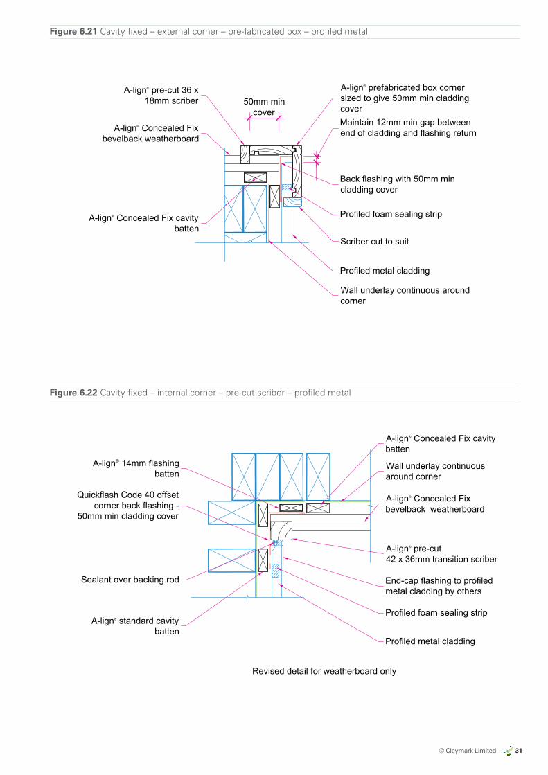
© Claymark Limited 31
ALMOND
CLAYMARKRECOMMENDED BRAND APPROACH 14/06/17
EXPORT MARKETS
US
US
US
AUSTRALIA
AUSTRALIA
NZ DOMESTIC
by claymark
Profiles Select
Tru-Pine
by claymark
Solid gold™
by claymark
Centurion™
by claymarkG
by claymark
by claymark
by claymark
Premium Pineby claymark
Figure 6.21 Cavity fixed – external corner – pre-fabricated box – profiled metal
A-lign® prefabricated box cornersized to give 50mm min claddingcover
A-lign® pre-cut 36 x18mm scriber 50mm min
coverMaintain 12mm min gap betweenend of cladding and flashing return
Back flashing with 50mm mincladding cover
Profiled foam sealing strip
Scriber cut to suit
Profiled metal cladding
Wall underlay continuous aroundcorner
A-lign® Concealed Fix cavitybatten
A-lign® Concealed Fixbevelback weatherboard
All Dimensions are tobe site checkedbefore constructionand installation
Claymark Align® Concealed Fix Details
Concealed Fix bevelback weatherboard - cavity - ext corner - pre-fab box - profiled metal
fig6-21_cv_ext_box_crn_p_met.dwg 19 July 2017Scale at A4 1:5
Version 2.0
Fig 6-21
Figure 6.22 Cavity fixed – internal corner – pre-cut scriber – profiled metal
Wall underlay continuousaround corner
Quickflash Code 40 offsetcorner back flashing -
50mm min cladding cover
A-lign® Concealed Fixbevelback weatherboard
A-lign® pre-cut42 x 36mm transition scriber
End-cap flashing to profiledmetal cladding by others
Profiled foam sealing strip
Profiled metal cladding
Sealant over backing rod
A-lign® standard cavitybatten
A-lign® 14mm flashingbatten
A-lign® Concealed Fix cavitybatten
Revised detail for weatherboard only
All Dimensions are tobe site checkedbefore constructionand installation
Claymark Align® Concealed Fix Details
Concealed Fix bevelback weatherboard - cavity - int corner - pre-cut scriber - prof metal
fig6-22_cv_int_crn_p_met.dwg 19 July 2017Scale at A4 1:5
Version 2.0
Fig 6-22
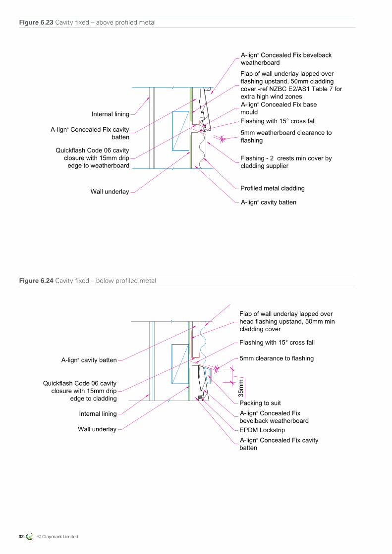
32 © Claymark Limited
ALMOND
CLAYMARKRECOMMENDED BRAND APPROACH 14/06/17
EXPORT MARKETS
US
US
US
AUSTRALIA
AUSTRALIA
NZ DOMESTIC
by claymark
Profiles Select
Tru-Pine
by claymark
Solid gold™
by claymark
Centurion™
by claymarkG
by claymark
by claymark
by claymark
Premium Pineby claymark
Figure 6.23 Cavity fixed – above profiled metal
A-lign® Concealed Fix bevelbackweatherboard
Internal lining
Flap of wall underlay lapped overflashing upstand, 50mm claddingcover -ref NZBC E2/AS1 Table 7 forextra high wind zones
Flashing with 15° cross fall
5mm weatherboard clearance toflashing
Flashing - 2 crests min cover bycladding supplier
Wall underlay Profiled metal cladding
A-lign® cavity batten
A-lign® Concealed Fix cavitybatten
Quickflash Code 06 cavityclosure with 15mm drip
edge to weatherboard
A-lign® Concealed Fix basemould
All Dimensions are tobe site checkedbefore constructionand installation
Claymark Align® Concealed Fix Details
Concealed Fix bevelback weatherboard - cavity - above profiled metal
fig6-23_cv_above_p_met.dwg 19 July 2017Scale at A4 1:5
Version 2.0
Fig 6-23
Figure 6.24 Cavity fixed – below profiled metal
Profiled metal cladding
Quickflash Code 06 cavityclosure with 15mm drip
edge to cladding
A-lign® cavity batten
Flap of wall underlay lapped overhead flashing upstand, 50mm mincladding cover
Flashing with 15° cross fall
5mm clearance to flashing
Wall underlay
A-lign® Concealed Fixbevelback weatherboard
A-lign® Concealed Fix cavitybatten
35m
m
Internal liningPacking to suit
EPDM Lockstrip
All Dimensions are tobe site checkedbefore constructionand installation
Claymark Align® Concealed Fix Details
Concealed Fix bevelback weatherboard - cavity - below profiled metal
fig6-24_cv_below_p_met.dwg 19 July 2017Scale at A4 1:5
Version 2.0
Fig 6-24
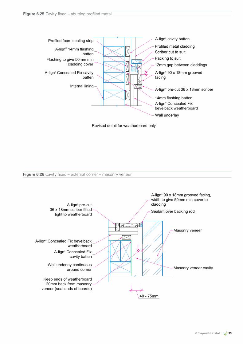
© Claymark Limited 33
ALMOND
CLAYMARKRECOMMENDED BRAND APPROACH 14/06/17
EXPORT MARKETS
US
US
US
AUSTRALIA
AUSTRALIA
NZ DOMESTIC
by claymark
Profiles Select
Tru-Pine
by claymark
Solid gold™
by claymark
Centurion™
by claymarkG
by claymark
by claymark
by claymark
Premium Pineby claymark
Figure 6.25 Cavity fixed – abutting profiled metal
Flashing to give 50mm mincladding cover
Profiled metal claddingScriber cut to suit
12mm gap between claddings
A-lign® 90 x 18mm groovedfacing
A-lign® pre-cut 36 x 18mm scriber
14mm flashing battenA-lign® Concealed Fixbevelback weatherboard
Wall underlay
Internal lining
Profiled foam sealing strip
Packing to suit
A-lign® Concealed Fix cavitybatten
Revised detail for weatherboard only
A-lign® 14mm flashingbatten
A-lign® cavity batten
All Dimensions are tobe site checkedbefore constructionand installation
Claymark Align® Concealed Fix Details
Concealed Fix bevelback weatherboard - cavity - abutting profiled metal
fig6-25_cv_abut_p_met.dwg 19 July 2017Scale at A4 1:5
Version 2.0
Fig 6-25
Figure 6.26 Cavity fixed – external corner – masonry veneer
A-lign® 90 x 18mm grooved facing,width to give 50mm min cover tocladdingA-lign® pre-cut
36 x 18mm scriber fittedtight to weatherboard
Sealant over backing rod
Masonry veneer
Masonry veneer cavity
A-lign® Concealed Fix bevelbackweatherboard
A-lign® Concealed Fixcavity batten
Wall underlay continuousaround corner
Keep ends of weatherboard20mm back from masonry
veneer (seal ends of boards)
40 - 75mm
All Dimensions are tobe site checkedbefore constructionand installation
Claymark Align® Concealed Fix Details
Concealed Fix bevelback weatherboard - cavity - external corner - masonry veneer
fig6-26_cv_ext_cnr_m_ven.dwg 19 July 2017Scale at A4 1:5
Version 2.0
Fig 6-26
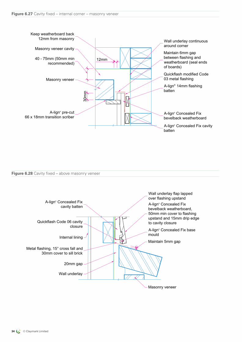
34 © Claymark Limited
ALMOND
CLAYMARKRECOMMENDED BRAND APPROACH 14/06/17
EXPORT MARKETS
US
US
US
AUSTRALIA
AUSTRALIA
NZ DOMESTIC
by claymark
Profiles Select
Tru-Pine
by claymark
Solid gold™
by claymark
Centurion™
by claymarkG
by claymark
by claymark
by claymark
Premium Pineby claymark
Figure 6.27 Cavity fixed – internal corner – masonry veneer
Wall underlay continuousaround corner
40 - 75mm (50mm minrecommended)
30m
m
12mm
Maintain 6mm gapbetween flashing andweatherboard (seal endsof boards)
Quickflash modified Code03 metal flashing
A-lign® 14mm flashingbatten
A-lign® Concealed Fixbevelback weatherboard
A-lign® pre-cut66 x 18mm transition scriber
Masonry veneer
Masonry veneer cavity
A-lign® Concealed Fix cavitybatten
Keep weatherboard back12mm from masonry
All Dimensions are tobe site checkedbefore constructionand installation
Claymark Align® Concealed Fix Details
Concealed Fix bevelback weatherboard - cavity - internal corner - masonry veneer
fig6-27_cv_int_cnr_m_ven.dwg 19 July 2017Scale at A4 1:5
Version 2.0
Fig 6-27
Figure 6.28 Cavity fixed – above masonry veneer
Wall underlay flap lappedover flashing upstandA-lign® Concealed Fixbevelback weatherboard,50mm min cover to flashingupstand and 15mm drip edgeto cavity closure
Metal flashing, 15° cross fall and30mm cover to sill brick
Maintain 5mm gap
20mm gap
Wall underlay
Masonry veneer
A-lign® Concealed Fixcavity batten
Quickflash Code 06 cavityclosure
Internal lining
A-lign® Concealed Fix basemould
All Dimensions are tobe site checkedbefore constructionand installation
Claymark Align® Concealed Fix Details
Concealed Fix bevelback weatherboard - cavity - above masonry veneer
fig6-28_cv_above_m_ven.dwg 19 July 2017Scale at A4 1:5
Version 2.0
Fig 6-28
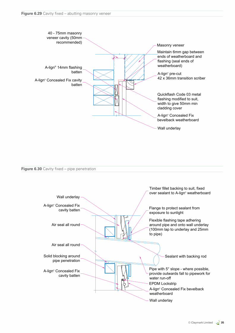
© Claymark Limited 35
ALMOND
CLAYMARKRECOMMENDED BRAND APPROACH 14/06/17
EXPORT MARKETS
US
US
US
AUSTRALIA
AUSTRALIA
NZ DOMESTIC
by claymark
Profiles Select
Tru-Pine
by claymark
Solid gold™
by claymark
Centurion™
by claymarkG
by claymark
by claymark
by claymark
Premium Pineby claymark
Figure 6.29 Cavity fixed – abutting masonry veneer
Masonry veneer
Maintain 6mm gap betweenends of weatherboard andflashing (seal ends ofweatherboard)
A-lign® pre-cut42 x 36mm transition scriber
Quickflash Code 03 metalflashing modified to suit,width to give 50mm mincladding cover
A-lign® Concealed Fixbevelback weatherboard
Wall underlay
A-lign® 14mm flashingbatten
40 - 75mm masonryveneer cavity (50mm
recommended)
A-lign® Concealed Fix cavitybatten
All Dimensions are tobe site checkedbefore constructionand installation
Claymark Align® Concealed Fix Details
Concealed Fix bevelback weatherboard - cavity - abutting masonry veneer
fig6-29_cv_abut_m_ven.dwg 19 July 2017Scale at A4 1:5
Version 2.0
Fig 6-29
Figure 6.30 Cavity fixed – pipe penetration
Timber fillet backing to suit, fixedover sealant to A-lign® weatherboard
Flexible flashing tape adheringaround pipe and onto wall underlay(100mm lap to underlay and 25mmto pipe)
Flange to protect sealant fromexposure to sunlight
Sealant with backing rod
A-lign® Concealed Fix bevelbackweatherboard
Wall underlay
A-lign® Concealed Fixcavity batten
Solid blocking aroundpipe penetration
Air seal all round
Air seal all round
A-lign® Concealed Fixcavity batten
Pipe with 5° slope - where possible,provide outwards fall to pipework forwater run-off
Wall underlay
EPDM Lockstrip
All Dimensions are tobe site checkedbefore constructionand installation
Claymark Align® Concealed Fix Details
Concealed Fix bevelback weatherboard - cavity - pipe penetration
fig6-30_cv_pipe_pene.dwg 19 July 2017Scale at A4 1:5
Version 2.0
Fig 6-30
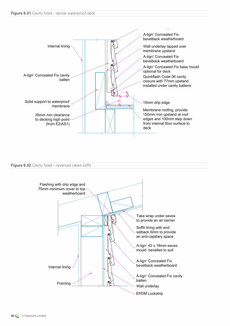
36 © Claymark Limited
ALMOND
CLAYMARKRECOMMENDED BRAND APPROACH 14/06/17
EXPORT MARKETS
US
US
US
AUSTRALIA
AUSTRALIA
NZ DOMESTIC
by claymark
Profiles Select
Tru-Pine
by claymark
Solid gold™
by claymark
Centurion™
by claymarkG
by claymark
by claymark
by claymark
Premium Pineby claymark
Figure 6.31 Cavity fixed – above waterproof deck
A-lign® Concealed Fixbevelback weatherboard
Wall underlay lapped overmembrane upstandA-lign® Concealed Fixbevelback weatherboard
Membrane roofing, provide150mm min upstand at roofedges and 100mm step downfrom internal floor surface todeck
Solid support to waterproofmembrane
35mm min clearanceto decking high point
(from E2/AS1)
A-lign® Concealed Fix cavitybatten
Quickflash Code 06 cavityclosure with 77mm upstandinstalled under cavity battens
15mm drip edge
Internal lining
A-lign® Concealed Fix base mouldoptional for deck
EPDM Lockstrip
All Dimensions are tobe site checkedbefore constructionand installation
Claymark Align® Concealed Fix Details
Concealed Fix bevelback weatherboard - cavity - above waterproof deck
fig6-31_cv_abov_wprf_dec.dwg 19 July 2017Scale at A4 1:5
Version 2.0
Fig 6-31
Figure 6.32 Cavity fixed – reversed raked soffit
FramingWall underlay
Soffit lining with endsetback 6mm to providean anti-capillary space
Flashing with drip edge and75mm minimum cover to top
weatherboard
A-lign® Concealed Fixbevelback weatherboard
Take wrap under eavesto provide an air barrier
A-lign® 42 x 18mm eavesmould bevelled to suit
A-lign® Concealed Fix cavitybatten
Internal lining
EPDM Lockstrip
All Dimensions are tobe site checkedbefore constructionand installation
Claymark Align® Concealed Fix Details
Concealed Fix bevelback weatherboard - cavity - reversed raked soffit
fig6-32_cv_rev_rake_sof.dwg 19 July 2017Scale at A4 1:5
Version 2.0
Fig 6-32
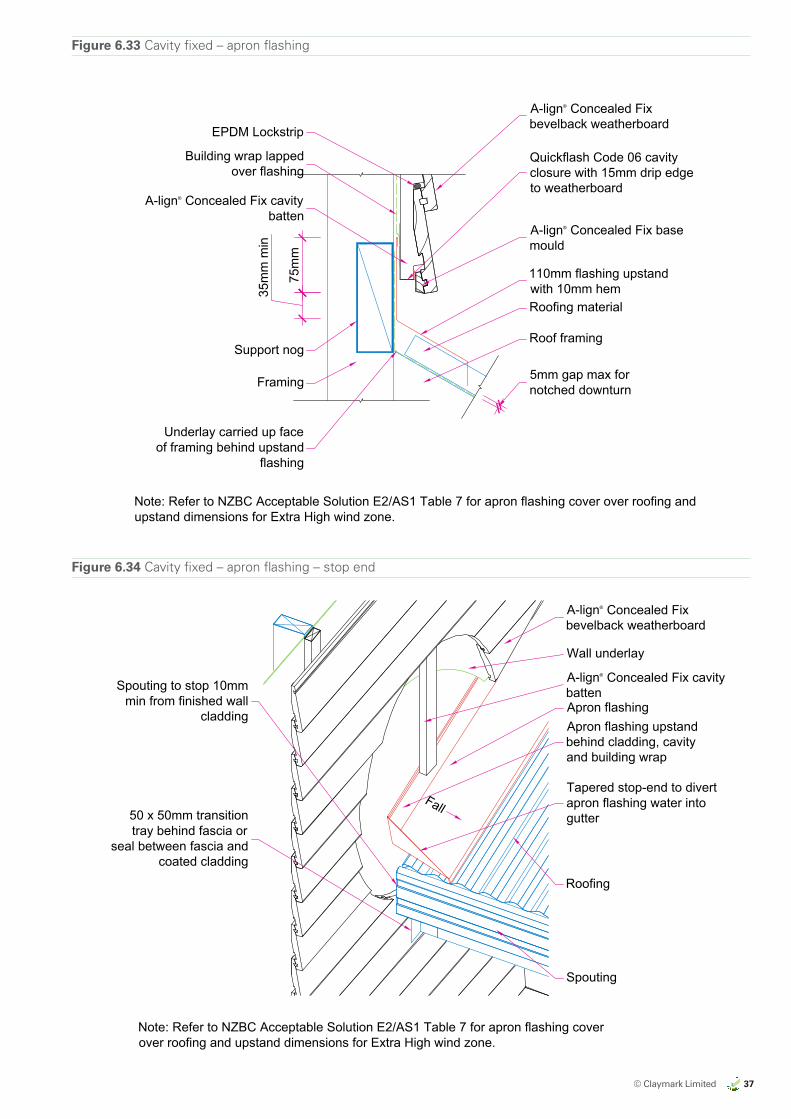
© Claymark Limited 37
ALMOND
CLAYMARKRECOMMENDED BRAND APPROACH 14/06/17
EXPORT MARKETS
US
US
US
AUSTRALIA
AUSTRALIA
NZ DOMESTIC
by claymark
Profiles Select
Tru-Pine
by claymark
Solid gold™
by claymark
Centurion™
by claymarkG
by claymark
by claymark
by claymark
Premium Pineby claymark
Figure 6.33 Cavity fixed – apron flashing
A-lign® Concealed Fix cavitybatten
Support nog
A-lign® Concealed Fixbevelback weatherboard
Quickflash Code 06 cavityclosure with 15mm drip edgeto weatherboard
110mm flashing upstandwith 10mm hemRoofing material
Underlay carried up faceof framing behind upstand
flashing
Framing
Roof framing
35m
m m
in
75m
m
5mm gap max fornotched downturn
A-lign® Concealed Fix basemould
Building wrap lappedover flashing
Note: Refer to NZBC Acceptable Solution E2/AS1 Table 7 for apron flashing cover over roofing andupstand dimensions for Extra High wind zone.
EPDM Lockstrip
All Dimensions are tobe site checkedbefore constructionand installation
Claymark Align® Concealed Fix Details
Concealed Fix bevelback weatherboard - cavity - apron flashing
fig6-33_cv_apron_flsh.dwg 19 July 2017Scale at A4 1:5
Version 2.0
Fig 6-33
Figure 6.34 Cavity fixed – apron flashing – stop end
Apron flashing
Roofing
A-lign® Concealed Fixbevelback weatherboard
A-lign® Concealed Fix cavitybatten
Spouting
Apron flashing upstandbehind cladding, cavityand building wrap
Tapered stop-end to divertapron flashing water intogutter
Spouting to stop 10mmmin from finished wall
cladding
50 x 50mm transitiontray behind fascia or
seal between fascia andcoated cladding
Wall underlay
Note: Refer to NZBC Acceptable Solution E2/AS1 Table 7 for apron flashing coverover roofing and upstand dimensions for Extra High wind zone.
Fall
All Dimensions are tobe site checkedbefore constructionand installation
Claymark Align® Concealed Fix Details
Concealed Fix bevelback weatherboard - cavity - apron flashing - stop end
fig6-34_cv_apron_stop.dwg 19 July 2017Scale at A4 1:10
Version 2.0
Fig 6-34
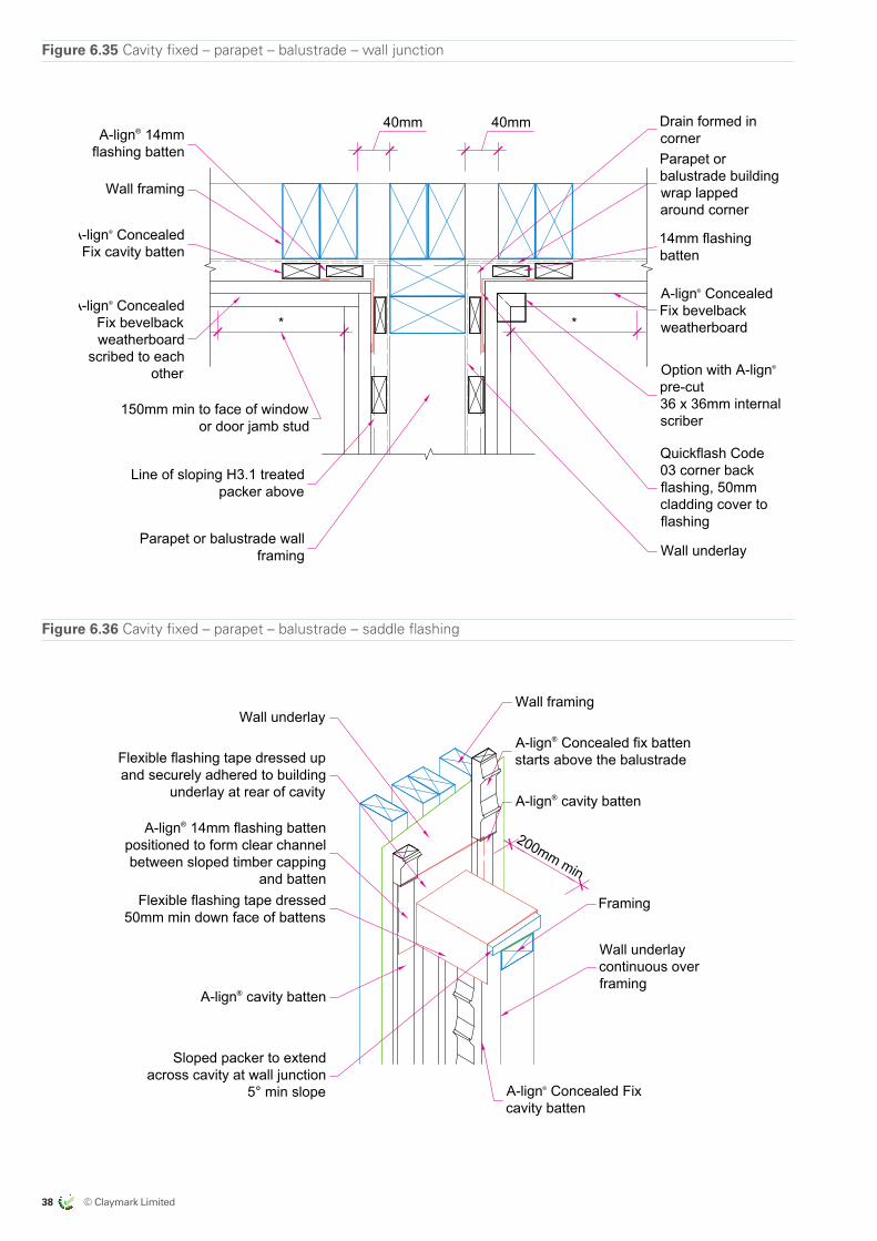
38 © Claymark Limited
ALMOND
CLAYMARKRECOMMENDED BRAND APPROACH 14/06/17
EXPORT MARKETS
US
US
US
AUSTRALIA
AUSTRALIA
NZ DOMESTIC
by claymark
Profiles Select
Tru-Pine
by claymark
Solid gold™
by claymark
Centurion™
by claymarkG
by claymark
by claymark
by claymark
Premium Pineby claymark
Figure 6.35 Cavity fixed – parapet – balustrade – wall junction
Parapet or balustrade wallframing Wall underlay
Quickflash Code03 corner backflashing, 50mmcladding cover toflashing
A-lign® ConcealedFix bevelbackweatherboard
Line of sloping H3.1 treatedpacker above
14mm flashingbatten
Parapet orbalustrade buildingwrap lappedaround corner
*
150mm min to face of windowor door jamb stud
Wall framing
Drain formed incorner
40mm 40mm
Option with A-lign®
pre-cut36 x 36mm internalscriber
A-lign® ConcealedFix bevelbackweatherboard
scribed to eachother
*
A-lign® 14mmflashing batten
A-lign® ConcealedFix cavity batten
All Dimensions are tobe site checkedbefore constructionand installation
Claymark Align® Concealed Fix Details
Concealed Fix bevelback weatherboard - cavity - parapet - balustrade - wall junction
fig6-35_cv_para_plan.dwg 19 July 2017Scale at A4 1:5
Version 2.0
Fig 6-35
Figure 6.36 Cavity fixed – parapet – balustrade – saddle flashing
Wall framing
A-lign® cavity batten
Framing
Wall underlay
A-lign® 14mm flashing battenpositioned to form clear channelbetween sloped timber capping
and batten
A-lign® Concealed Fixcavity batten
Sloped packer to extendacross cavity at wall junction
5° min slope
Flexible flashing tape dressed upand securely adhered to building
underlay at rear of cavity
Flexible flashing tape dressed50mm min down face of battens
Wall underlaycontinuous overframing
200mm min
A-lign® cavity batten
A-lign® Concealed fix battenstarts above the balustrade
All Dimensions are tobe site checkedbefore constructionand installation
Claymark Align® Concealed Fix Details
Concealed Fix bevelback weatherboard - cavity - parapet - balustrade - saddle flashing
fig6-36_cv_saddle_flsh.dwg 19 July 2017Scale at A4 1:10
Version 2.0
Fig 6-36
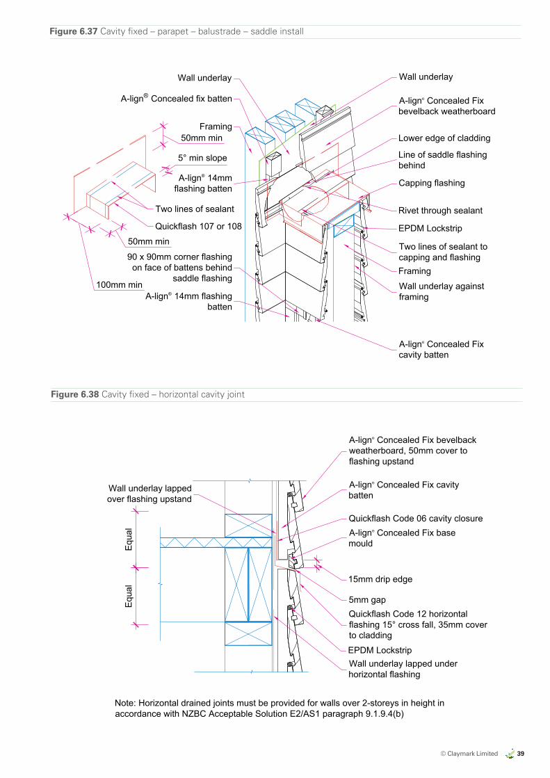
© Claymark Limited 39
ALMOND
CLAYMARKRECOMMENDED BRAND APPROACH 14/06/17
EXPORT MARKETS
US
US
US
AUSTRALIA
AUSTRALIA
NZ DOMESTIC
by claymark
Profiles Select
Tru-Pine
by claymark
Solid gold™
by claymark
Centurion™
by claymarkG
by claymark
by claymark
by claymark
Premium Pineby claymark
Figure 6.37 Cavity fixed – parapet – balustrade – saddle install
Wall underlay
A-lign® Concealed Fixbevelback weatherboard
Line of saddle flashingbehind
Lower edge of cladding
Rivet through sealant
Two lines of sealant tocapping and flashingFraming
90 x 90mm corner flashingon face of battens behind
saddle flashing
Framing
Wall underlay
A-lign® 14mmflashing batten Capping flashing
Two lines of sealant
50mm min
100mm min
50mm min
5° min slope
A-lign® 14mm flashingbatten
Wall underlay againstframing
Quickflash 107 or 108
A-lign® Concealed Fixcavity batten
A-lign® Concealed fix batten
EPDM Lockstrip
All Dimensions are tobe site checkedbefore constructionand installation
Claymark Align® Concealed Fix Details
Concealed Fix bevelback weatherboard - cavity - parapet - balustrade - saddle install
fig6-37_cv_saddle_inst.dwg 19 July 2017Scale at A4 1:10
Version 2.0
Fig 6-37
Figure 6.38 Cavity fixed – horizontal cavity joint
A-lign® Concealed Fix bevelbackweatherboard, 50mm cover toflashing upstand
A-lign® Concealed Fix cavitybatten
Quickflash Code 06 cavity closureA-lign® Concealed Fix basemould
15mm drip edge
5mm gapQuickflash Code 12 horizontalflashing 15° cross fall, 35mm coverto cladding
Wall underlay lapped underhorizontal flashing
Wall underlay lappedover flashing upstand
Note: Horizontal drained joints must be provided for walls over 2-storeys in height inaccordance with NZBC Acceptable Solution E2/AS1 paragraph 9.1.9.4(b)
Equa
lEq
ual
EPDM Lockstrip
All Dimensions are tobe site checkedbefore constructionand installation
Claymark Align® Concealed Fix Details
Concealed Fix bevelback weatherboard - cavity - horizontal cavity joint
fig6-38_cv_hori_joint.dwg 19 July 2017Scale at A4 1:5
Version 2.0
Fig 6-38
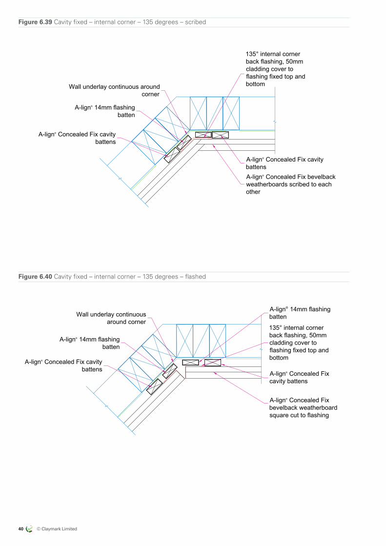
40 © Claymark Limited
ALMOND
CLAYMARKRECOMMENDED BRAND APPROACH 14/06/17
EXPORT MARKETS
US
US
US
AUSTRALIA
AUSTRALIA
NZ DOMESTIC
by claymark
Profiles Select
Tru-Pine
by claymark
Solid gold™
by claymark
Centurion™
by claymarkG
by claymark
by claymark
by claymark
Premium Pineby claymark
Figure 6.39 Cavity fixed – internal corner – 135 degrees – scribed
A-lign® Concealed Fix cavitybattensA-lign® Concealed Fix bevelbackweatherboards scribed to eachother
Wall underlay continuous aroundcorner
135° internal cornerback flashing, 50mmcladding cover toflashing fixed top andbottom
A-lign® Concealed Fix cavitybattens
A-lign® 14mm flashingbatten
All Dimensions are tobe site checkedbefore constructionand installation
Claymark Align® Concealed Fix Details
Concealed Fix bevelback weatherboard - cavity - internal corner - 135 degrees - scribed
fig6-39_cv_int_135_corner.dwg 19 July 2017Scale at A4 1:5
Version 2.0
Fig 6-39
Figure 6.40 Cavity fixed – internal corner – 135 degrees – flashed
A-lign® 14mm flashingbatten
A-lign® Concealed Fixbevelback weatherboardsquare cut to flashing
Wall underlay continuousaround corner
A-lign® Concealed Fix cavitybattens
A-lign® 14mm flashingbatten
A-lign® Concealed Fixcavity battens
135° internal cornerback flashing, 50mmcladding cover toflashing fixed top andbottom
All Dimensions are tobe site checkedbefore constructionand installation
Claymark Align® Concealed Fix Details
Concealed Fix bevelback weatherboard - cavity - internal corner - 135 degrees - flashed
fig6-40_cv_int_135_corner.dwg 19 July 2017Scale at A4 1:5
Version 2.0
Fig 6-40
A-lign® 14mm flashingbatten
A-lign® Concealed Fixbevelback weatherboardsquare cut to flashing
Wall underlay continuousaround corner
A-lign® Concealed Fix cavitybattens
A-lign® 14mm flashingbatten
A-lign® Concealed Fixcavity battens
135° internal cornerback flashing, 50mmcladding cover toflashing fixed top andbottom
All Dimensions are tobe site checkedbefore constructionand installation
Claymark Align® Concealed Fix Details
Concealed Fix bevelback weatherboard - cavity - internal corner - 135 degrees - flashed
fig6-40_cv_int_135_corner.dwg 19 July 2017Scale at A4 1:5
Version 2.0
Fig 6-40
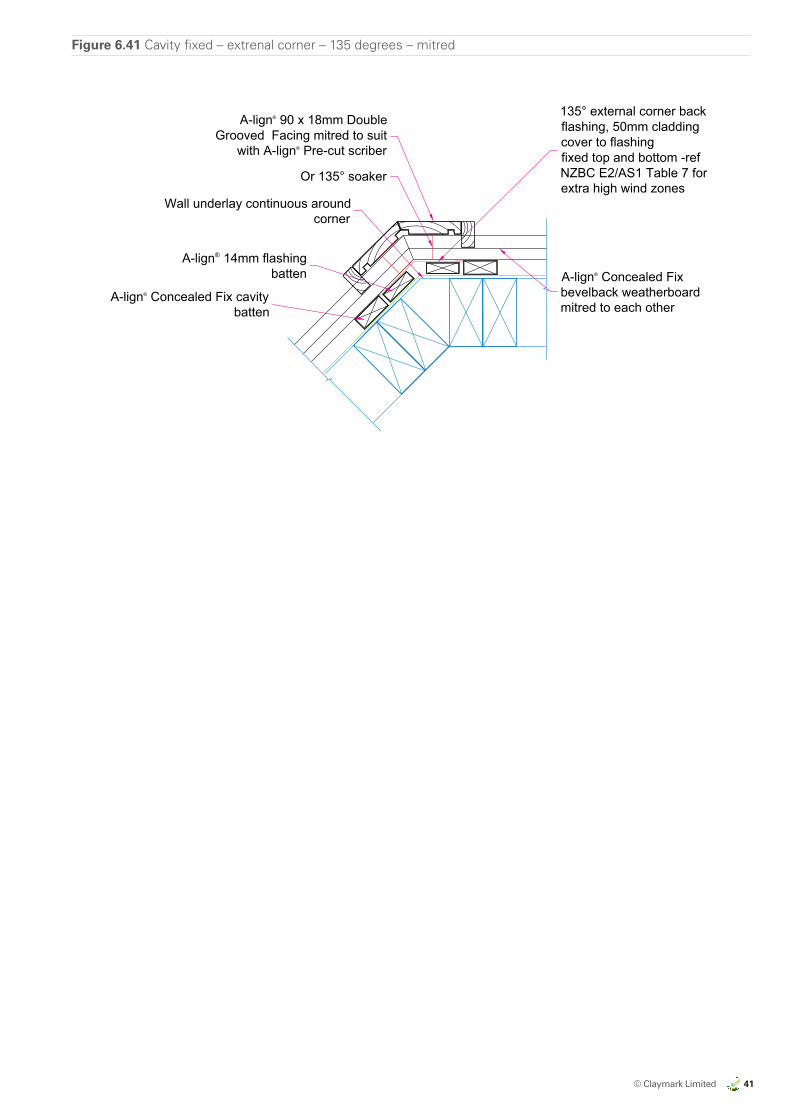
© Claymark Limited 41
ALMOND
CLAYMARKRECOMMENDED BRAND APPROACH 14/06/17
EXPORT MARKETS
US
US
US
AUSTRALIA
AUSTRALIA
NZ DOMESTIC
by claymark
Profiles Select
Tru-Pine
by claymark
Solid gold™
by claymark
Centurion™
by claymarkG
by claymark
by claymark
by claymark
Premium Pineby claymark
Figure 6.41 Cavity fixed – extrenal corner – 135 degrees – mitred
A-lign® Concealed Fixbevelback weatherboardmitred to each other
Wall underlay continuous aroundcorner
135° external corner backflashing, 50mm claddingcover to flashingfixed top and bottom -refNZBC E2/AS1 Table 7 forextra high wind zones
A-lign® 14mm flashingbatten
A-lign® 90 x 18mm DoubleGrooved Facing mitred to suit
with A-lign® Pre-cut scriber
Or 135° soaker
A-lign® Concealed Fix cavitybatten
All Dimensions are tobe site checkedbefore constructionand installation
Claymark Align® Concealed Fix Details
Concealed Fix bevelback weatherboard - cavity - external corner - 135 degrees - mitred
fig6-41_cv_ext_135_corner.dwg 19 July 2017Scale at A4 1:5
Version 2.0
Fig 6-41
42 © Claymark Limited
ALMOND
CLAYMARKRECOMMENDED BRAND APPROACH 14/06/17
EXPORT MARKETS
US
US
US
AUSTRALIA
AUSTRALIA
NZ DOMESTIC
by claymark
Profiles Select
Tru-Pine
by claymark
Solid gold™
by claymark
Centurion™
by claymarkG
by claymark
by claymark
by claymark
Premium Pineby claymark
Claymark Limited – Quality
Claymark quality assurance standardsTo constantly deliver products that perform at the highest level demands excellent standards of quality in every area of business: from the training of our people, to product improvement, to concern for the environment.
We at Claymark Limited are proud of our reputation for quality and integrity. A reputation that has been proven for generations. Our investment in quality is core to our company philosophy. Out of that dedication, innovation flows – and excellence continues year after year.
Our most recent certifications and standards are shown here. We will update these regularly. We strive to not just follow the strictest standards of our profession but to keep ahead of them. That way you, our customer, know that whenever you choose a product or service, you are choosing real quality.
Forest Stewardship Council® – chain of custodyTimber has been independently certified by Scientific Certification Systems (SCS) in accordance with the rules of the Forest Stewardship Council® A.C. (FSC®).
SCS Certification Registration Number SCS-COC-000679
Timber Preservation Quality Manual. License number 080
New Zealand Forest Industries CouncilTimber was awarded the champion training company for solid wood processing in 2001. The certificate was awarded by Forest Industries Training and Education Council.
Refer to www.claymark.co.nz for information on quality control methods.
For more information about our independent third party quality audit process contact us at:
0800 25 44 61 Monday to Friday 8am–5pm

© C
laym
ark
Ltd
2017
. All
right
s re
serv
ed. A
ll in
telle
ctua
l pro
pert
y an
d im
ages
incl
uded
in th
is Te
chni
cal M
anua
l and
in th
e A
-lign
sol
utio
n ar
e ow
ned
by C
laym
ark
Ltd
and
cann
ot b
e us
ed w
ithou
t (w
ritte
n) c
onse
nt o
f the
cop
yrig
ht o
wne
r. N
o m
ater
ial i
n th
is d
ocum
ent m
ay b
e co
pied
with
out t
he e
xpre
ss (w
ritte
n) c
onse
nt o
f Cla
ymar
k Lt
d A
ll ap
plic
atio
ns fo
r re
prod
uctio
n, in
any
form
, sho
uld
be m
ade
to C
laym
ark
Ltd
Cla
ymar
k Lt
d re
serv
es th
e rig
ht to
revi
se, w
ithou
t not
ice,
any
info
rmat
ion
cont
aine
d in
this
doc
umen
t. A
lthou
gh e
very
effo
rt h
as b
een
mad
e to
ens
ure
the
info
rmat
ion
cont
aine
d in
this
doc
umen
t com
plie
s w
ith e
xist
ing
build
ing
stan
dard
s an
d re
cogn
ised
cod
es o
f pra
ctic
e, n
o re
spon
sibi
lity
is a
ccep
ted
for
any
erro
rs a
nd o
mis
sion
s in
thi
s do
cum
ent,
nor
for
any
spe
cific
atio
ns o
r w
ork
base
d up
on t
his
info
rmat
ion.
Som
e of
the
se im
ages
dep
ict T
ru-P
ine
wea
ther
boar
ds. T
hese
boa
rds
are
near
ly id
entic
al t
o th
ose
used
in t
he A
-lign
sol
utio
n an
d di
ffer
only
slig
htly
in s
ize
to t
he A
-lign
wea
ther
boar
ds a
nd d
iffer
in c
erta
in c
onst
ruct
ion
feat
ures
whi
ch a
re n
ot
visi
ble
exte
rnal
ly.
ALMOND
CLAYMARKRECOMMENDED BRAND APPROACH 14/06/17
EXPORT MARKETS
US
US
US
AUSTRALIA
AUSTRALIA
NZ DOMESTIC
by claymark
Profiles Select
Tru-Pine
by claymark
Solid gold™
by claymark
Centurion™
by claymarkG
by claymark
by claymark
by claymark
Premium Pineby claymark
claymark.co.nz
For more information call the Claymark Helpline Toll Free
0800 25 44 61Monday to Friday 8am–5pm