a lesson in the physics of hybrid electric vehicles · a lesson in the physics of hybrid electric...
TRANSCRIPT

A Lesson in the Physics of Hybrid Electric Vehicles
Karen I. BurkePhysics 451-45227 April 2000
1
Table of Contents
Preface . . . . . . . . . . . . . . . . . . . . . . . . . . . . . . . . . . . . . . . . . . . . . . . . . . . . . . . . . . . . . . . . 2
Abstract . . . . . . . . . . . . . . . . . . . . . . . . . . . . . . . . . . . . . . . . . . . . . . . . . . . . . . . . . . . . . . . 2
Introduction to Hybrid Electric Vehicles . . . . . . . . . . . . . . . . . . . . . . . . . . . . . . . . . . . . . . 3Series Configuration . . . . . . . . . . . . . . . . . . . . . . . . . . . . . . . . . . . . . . . . . . . . . . . 3Parallel Configuration . . . . . . . . . . . . . . . . . . . . . . . . . . . . . . . . . . . . . . . . . . . . . . 4Comparison of the Two Control Systems . . . . . . . . . . . . . . . . . . . . . . . . . . . . . . . 5
Internal Combustion Engine: Fundamentals and Efficiencies . . . . . . . . . . . . . . . . . . . . . 6 Basic operating principles . . . . . . . . . . . . . . . . . . . . . . . . . . . . . . . . . . . . . . . . . . . 7Thermal Efficiency . . . . . . . . . . . . . . . . . . . . . . . . . . . . . . . . . . . . . . . . . . . . . . . . . 8Island of Minimum Brake Specific Fuel Consumption . . . . . . . . . . . . . . . . . . . . . . 9Mechanical Efficiency/Friction Work . . . . . . . . . . . . . . . . . . . . . . . . . . . . . . . . . 11Combustion Efficiency . . . . . . . . . . . . . . . . . . . . . . . . . . . . . . . . . . . . . . . . . . . . . 12Volumetric Efficiency . . . . . . . . . . . . . . . . . . . . . . . . . . . . . . . . . . . . . . . . . . . . . . 13Heat Transfer . . . . . . . . . . . . . . . . . . . . . . . . . . . . . . . . . . . . . . . . . . . . . . . . . . . . 15Emissions . . . . . . . . . . . . . . . . . . . . . . . . . . . . . . . . . . . . . . . . . . . . . . . . . . . . . . . 15
Electric Motors . . . . . . . . . . . . . . . . . . . . . . . . . . . . . . . . . . . . . . . . . . . . . . . . . . . . . . . . . 17Synchronous Motors . . . . . . . . . . . . . . . . . . . . . . . . . . . . . . . . . . . . . . . . . . . . . . . 19AC Induction Motors . . . . . . . . . . . . . . . . . . . . . . . . . . . . . . . . . . . . . . . . . . . . . . 21Motor Control . . . . . . . . . . . . . . . . . . . . . . . . . . . . . . . . . . . . . . . . . . . . . . . . . . . 24
A Generic Control Strategy . . . . . . . . . . . . . . . . . . . . . . . . . . . . . . . . . . . . . . . . . . . . . . . 26
Conclusion . . . . . . . . . . . . . . . . . . . . . . . . . . . . . . . . . . . . . . . . . . . . . . . . . . . . . . . . . . . . 28
Appendix: The Article . . . . . . . . . . . . . . . . . . . . . . . . . . . . . . . . . . . . . . . . . . . . . . . . . . . 30Preface . . . . . . . . . . . . . . . . . . . . . . . . . . . . . . . . . . . . . . . . . . . . . . . . . . . . . . . . . 30A Lesson in the Physics of Hybrid Electric Vehicles . . . . . . . . . . . . . . . . . . . . . . 30
Half Gasoline . . . . . . . . . . . . . . . . . . . . . . . . . . . . . . . . . . . . . . . . . . . . . . 33Half Electric . . . . . . . . . . . . . . . . . . . . . . . . . . . . . . . . . . . . . . . . . . . . . . . 38The Hybrid Electric Vehicle . . . . . . . . . . . . . . . . . . . . . . . . . . . . . . . . . . . 41
References . . . . . . . . . . . . . . . . . . . . . . . . . . . . . . . . . . . . . . . . . . . . . . . . . . . . . . . . . . . . 44
2
Preface
There is growing interest worldwide in the incorporation of hybrid electric vehicles in
the automotive consumer market. The U.S. government and major U.S. car companies have
united in the Partnership for a New Generation of Vehicles1, which has designated that hybrid
electric vehicles will be an important step on the way to its goal of tripling fuel economy.
Hybrid electric vehicles are appearing as prototypes in auto shows and in some neighborhood
dealerships. This paper explores, in a twofold manner, the physical principles that permit the
hybrid electric vehicle to demonstrate higher fuel economy and lower emissions than the
traditional car. Firstly, these principles receive a scientific treatment. In the article appended to
this paper, I explain these physical principles to the non-scientific audience in a less technical
way.
Abstract
A hybrid drivetrain combines two modes of propulsion to achieve results that are
unproducible with a single drivetrain. This paper explores hybrid electric vehicles that employ a
spark-ignition internal combustion engine and an electric motor. The engine demonstrates
lowest brake specific fuel consumption at only a small region of its ranges of speed and load,
and demonstrates particularly high fuel consumption and high emissions use under transient
engine operation. The electric motor demonstrates high efficiency over the entire range of its
operations, and demonstrates high torque at low speeds. The hybrid electric vehicle combines
3
these features to minimize transient engine operation, to take advantage of the electric motor’s
suitability to acceleration. Many different configurations of the system are possible.
Introduction to Hybrid Electric Vehicles
Hybridization of the automotive drivetrain attempts to combine the low emissions of
electric automobiles with the extended range of gasoline engines. A hybrid electric vehicle
(HEV) increases the fuel economy and decreases the emissions of the system when compared
to a vehicle functioning only on a gasoline engine. The greatest benefit of the gasoline engine is
the high energy density2 of gasoline, on the order of 12,000 Wh/kg, in contrast with the much
lower energy density of batteries, on the order of 500 Wh/kg. This allows the much greater
range of vehicles run on gasoline engines. The benefits of electric motors include high torque at
low speeds, the absence of on-board emissions, and regenerative braking. Traditionally, there
are two ways to configure the system, series or parallel.
Series Configuration
In a series configuration, the gasoline engine is connected via a generator to the electric
motor, and only the electric motor provides power to the wheels. Torque produced by the
gasoline engine generates electric energy in the generator, which is stored in the battery for use
by the motor. In this system, the gasoline engine often runs continually in its zone of highest
efficiency or lowest emissions, eliminating transient operation of the engine.
Numerous types of control strategies are being employed with series configuration. The
gasoline engine can be controlled to optimize either fuel consumption or emissions production.

4
Design of the generator-motor system takes into consideration whether or not the car will be
“charge-dependent” or “self-sustaining.”2 A charge-dependent car relies on external electric
input whereas a self-sustaining car does not. The charge-dependent car, thus very similar to a
pure electric vehicle, releases fewer emissions; but the self-sustaining car demonstrates a longer
running range. Of the two, the self-sustaining car requires a generator of a larger capacity and
the charge-dependent car requires a battery of a larger capacity.
There are a number of other factors to be taken into consideration in the design and
control of series hybrid electric vehicles. The engine does not have to run consistently
throughout a driving cycle; thus, the number of times that an engine is started over the cycle is
an important variable in influencing the production of emissions.3 Another factor is the relation
of the battery’s state-of-charge and the traction motor output to the input from the gasoline
engine. In a “thermostat” strategy, the gasoline engine runs at a single power level; it is started
when the battery’s state-of-charge reaches a designated minimum and stops when the state-of-
charge has reached an upper set point.4 In a “power-follower” strategy, the gasoline engine
follows the immediate demands of the motor output, and the battery’s state-of-charge remains
constant5. Because this strategy matches the engine’s torque to the motor torque second-by-
second, bypassing the need to store the torque in the batteries, battery losses are reduced,
increasing fuel economy.4
Parallel Configuration
In a parallel configuration, either the gasoline engine or the electric motor, or both can
supply torque directly to the wheels. As a general principle, the electric motor is used for
5
starting and low vehicle speeds, and the gasoline engine provides the power for steady-state
operation. This configuration presents the designer with an even greater number of design
options than the series configuration. Control and control strategy are thus very important.
Control systems function primarily to match the drivetrain with the driving conditions.
Some principles are common to most parallel control systems. For example, the gasoline
engine is never allowed to idle. When the vehicle is stopped or when it is decelerating, the
engine is shut off. Only the electric motor provides torque for all slow-moving operations. A
minimum vehicle speed is usually set to govern the entrance of the gasoline engine. Both the
gasoline engine and the electric motor are used together for operations that demand high
torque. Regenerative braking is employed.
A number of factors vary among designs. Designers must choose a minimum speed
below which the gasoline engine is turned off. They also determine a minimum operating torque
as a function of engine speed for the gasoline engine4. If the torque required to meet the trace,
which is the instantaneous torque demand on the vehicle, falls beneath this mark, the excess
torque is used to drive the motor as a generator, recharging the batteries. A parallel-configured
hybrid can run the gasoline engine in a number of ways; the gasoline engine can be used to meet
the trace, it can be used only for steady-state operation, or there can be an intermediate control
strategy.
Comparison of the Two Control Systems
Control strategy in both series and parallel configuration is a significant determining
factor for the operations and performance of hybrid electric vehicles. Variations in strategy can
6
produce large variations in emissions production and fuel economy.4 The parallel configuration
is being most commonly chosen by automobile manufacturers. The operation of parallel
hybrids more closely resembles the operation of traditional cars than does the operation of
series hybrids, thus rendering them more appealing to the consumer. Also, the parallel hybrid
has been shown to be 4% more fuel efficient than the series hybrid, primarily because the
gasoline engine supplies power directly to the wheels, converting from mechanical power to
electrical power and back again, as occurs in the series hybrid.4
Internal Combustion Engine: Fundamentals and Efficiencies6,7
The design and success of the hybrid electric vehicle depends on certain characteristics
of the internal combustion engine. The internal combustion engine demonstrates highest fuel
efficiency and lowest emissions when it is run at cruising conditions in a small domain of its
torque-speed curve. Also, the engine’s fuel efficiency is limited to a theoretical maximum of
around 60% by the 2nd law of thermodynamics.
This analysis is made for the four-stroke (Otto cycle) spark-ignition engine, the most
commonly used for automobiles today. Some hybrid electric vehicles will use diesel engines,
and these have not been treated extensively in this paper. Like spark-ignition engines, diesel
engines also operate most efficiently in a small region of their torque and speed curves - the
characteristic of engines that most justifies the hybridization of the drivetrain. Most of the
analysis applies equally; however, diesel engines have a slightly different thermodynamic cycle.
7
Basic operating principles
The purpose of internal combustion engines is the production of mechanical power from
the chemical energy contained in the fuel. Each cylinder of the engine contains a piston; it is the
movement of the piston in response to the combustion of the engine that produces work.
During one cycle, the piston moves through the cylinder four times, each of which is called a
stroke. In the first stroke, the intake stroke, the piston travels down the cylinder creating a
vacuum, which pulls air into the cylinder, and fuel is added to the air. In the second stroke, the
compression stroke, the piston travels up the cylinder to its highest point, top dead center,
compressing the fuel-air mixture. Then combustion occurs; a spark ignites the gases, and
changes the composition of the mixture, raising the pressure and the temperature to their highest
values. In the third stroke, the expansion, or power stroke, the high pressure of the gases
pushes the piston down to its lowest point in the cylinder, bottom dead center. This produces
the work output of the cycle. Then, during exhaust blowdown, the exhaust valve is opened.
The pressure within the cylinder is higher than atmospheric pressure, so the exhaust gases leave
the cylinder. In the fourth stroke, the exhaust stroke, the cylinder starts full of exhaust gases at
atmospheric pressure. The piston moves from bottom dead center to top dead center, pushing
those gases out of the exhaust valve.
The work output of the cycle is created by the movement of the piston at high pressure
over the displacement volume.
As the volume under the integral is always the displacement volume and the pressure
8
continuously changes during the cycle, another parameter is defined: mean effective pressure,
the work per unit displaced volume.
where W is the work of one cycle and is the displacement volume. The torque of the
engine, the force acting at a moment distance, is defined as
N-m
where bmep is the brake mean effective pressure, the work applied to the crankshaft per unit
displaced volume. The appears in the denominator because, for the four-stroke cycle,
there are two revolutions per cycle. The power of the engine is the rate of work of the engine,
and is defined as follows:
where N is the engine speed in revolutions per minute, rpm, and n is the number of revolutions
per cycle.
Thermal Efficiency
The thermal efficiency of the internal combustion engine, determined by the second law
of thermodynamics, is defined as follows:
where is the heat of the reaction, and is the heat released to the environment. Taking
into account some characteristics of combustion, the mass of the fuel, , the heating value of
the fuel, , and the combustion efficiency, the percentage of fuel that combusts, , the
9
equation becomes the following:
The equation that follows is an equivalent way of writing the thermal efficiency equation for the
Otto cycle engine:
where is the compression ratio and is the adiabatic compressibility of air. With typical
values of 10 for the compression ratio, and 1.4 for adiabatic compressibility, the theoretical
thermal efficiency is .60. Actual performance of the internal combustion engine is even lower
than this theoretical efficiency because of heat losses, friction, air flow, and air-fuel equivalence
ratio.
An important quantity is the brake specific fuel consumption, defined as follows:
where is the rate of fuel flow into the engine and is the brake power, the power applied
to the crankshaft.
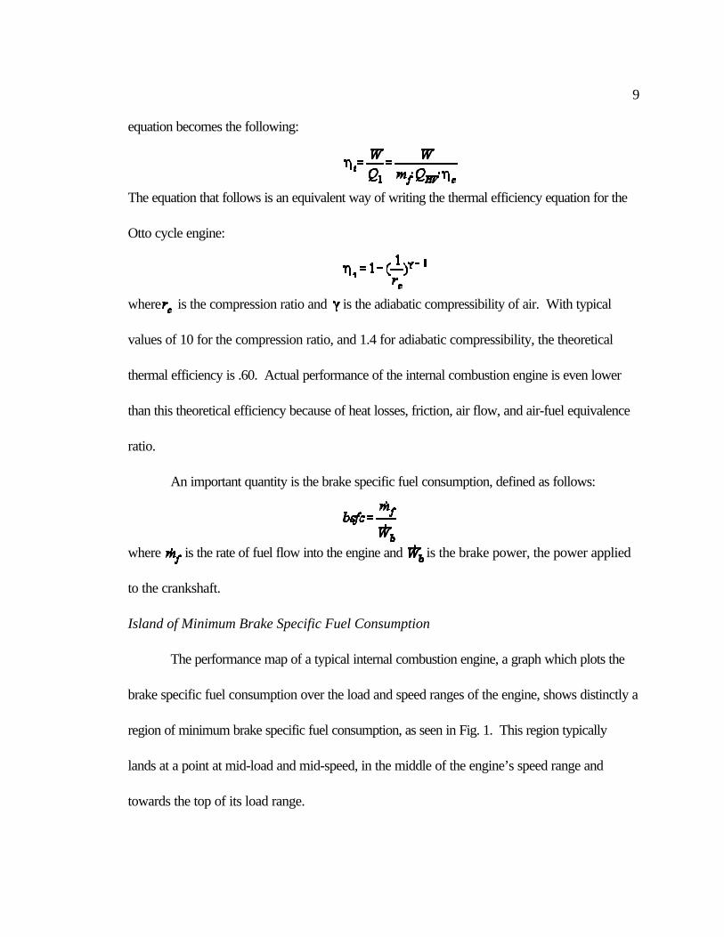
Island of Minimum Brake Specific Fuel Consumption
The performance map of a typical internal combustion engine, a graph which plots the
brake specific fuel consumption over the load and speed ranges of the engine, shows distinctly a
region of minimum brake specific fuel consumption, as seen in Fig. 1. This region typically
lands at a point at mid-load and mid-speed, in the middle of the engine’s speed range and
towards the top of its load range.
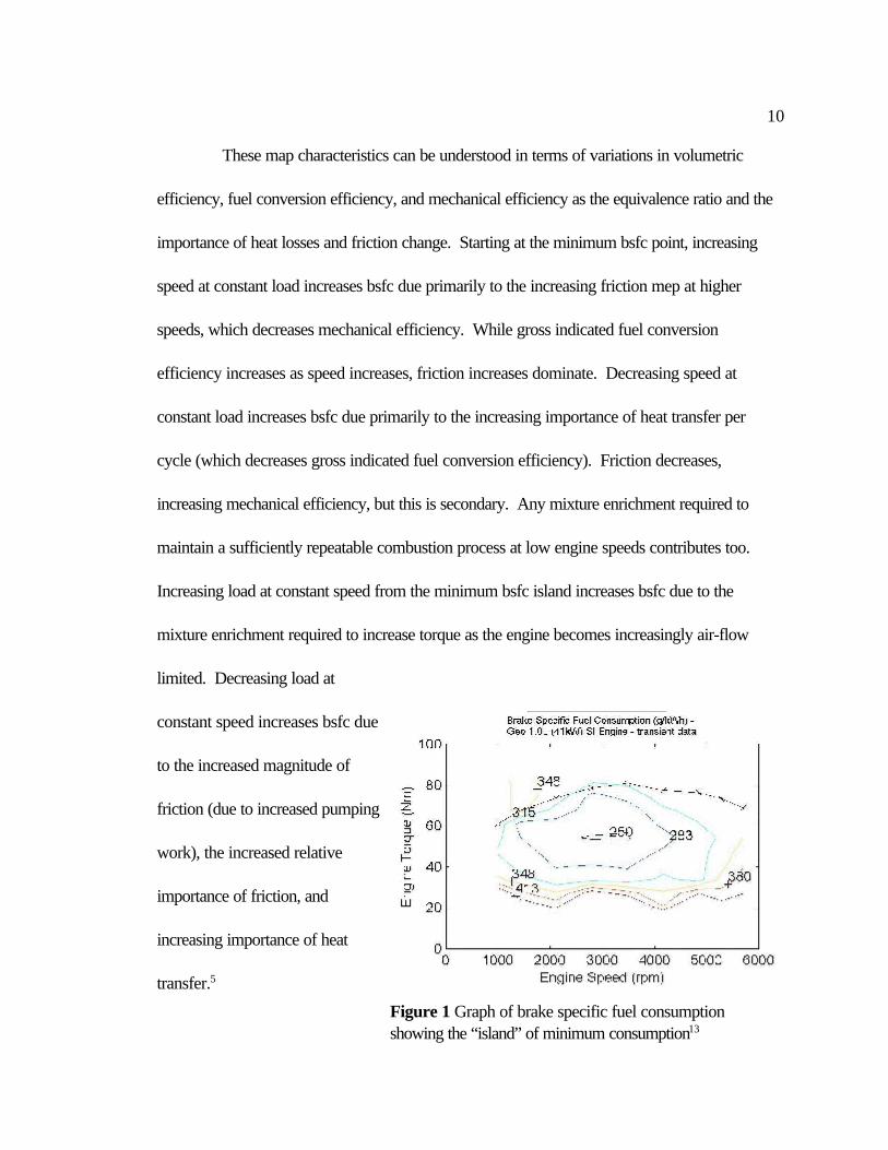
10
Figure 1 Graph of brake specific fuel consumptionshowing the “island” of minimum consumption13
These map characteristics can be understood in terms of variations in volumetric
efficiency, fuel conversion efficiency, and mechanical efficiency as the equivalence ratio and the
importance of heat losses and friction change. Starting at the minimum bsfc point, increasing
speed at constant load increases bsfc due primarily to the increasing friction mep at higher
speeds, which decreases mechanical efficiency. While gross indicated fuel conversion
efficiency increases as speed increases, friction increases dominate. Decreasing speed at
constant load increases bsfc due primarily to the increasing importance of heat transfer per
cycle (which decreases gross indicated fuel conversion efficiency). Friction decreases,
increasing mechanical efficiency, but this is secondary. Any mixture enrichment required to
maintain a sufficiently repeatable combustion process at low engine speeds contributes too.
Increasing load at constant speed from the minimum bsfc island increases bsfc due to the
mixture enrichment required to increase torque as the engine becomes increasingly air-flow
limited. Decreasing load at
constant speed increases bsfc due
to the increased magnitude of
friction (due to increased pumping
work), the increased relative
importance of friction, and
increasing importance of heat
transfer.5
11
Mechanical Efficiency/Friction Work
As engine speeds increase, the mechanical efficiency of the engine decreases, causing
the increase of brake specific fuel consumption. Mechanical efficiency is defined as the ratio of
work delivered to the crankshaft to work created in the compression and expansion strokes, or
the ratio of brake work to indicated work.
Friction work has three major components: 1) the friction work of the mechanical bearings, 2)
the pumping work to exhaust gases and induct fresh charge, and 3) the work needed to drive
the engine accessories. For all three of these components, friction work increases with
increasing engine speed.
Friction of the mechanical bearings can be approximated with the following quadratic
equation as a function of the speed of the engine, N:
is the constant for the frictional force components that are independent of speed, like
boundary friction. is the constant for the components that are proportional to speed, like
hydrodynamic friction, and is the constant for the components that are proportional to speed
squared, particularly turbulent dissipation. Hydrodynamic friction, the work needed to
overcome the viscous shear of the lubricated components, dominates. All of the following
individual mechanical bearings add to the friction work: water pump and alternator at no
charge; oil pump; valve train; pistons, rings, pins, and rods (without valves); and crankshaft and
seals.
12
Power requirements of the accessories similarly increase with increasing engine speed.
The engine fan, the engine generator, and the power-steering pump are major components.
The fan requirements are the largest and with a direct drive increase with the cube of the speed.
Mechanical efficiency, by definition, is also significantly affected by the load
requirements, independent of speed. At idling, zero load, mechanical efficiency is zero, and
increases with increasing load, from 0 to about 90%. Friction work also includes pumping
friction, the negative work of the intake and exhaust strokes. Pumping friction comprises
throttling friction and valve pumping friction, both of which increase with increasing speed at
constant load.
Combustion Efficiency
The combustion efficiency is the fraction of the energy of the fuel supplied which is
released in the combustion process.
where is the net chemical energy release. Combustion efficiency depends
primarily on the air-fuel equivalence ratio, , which is the stoichiometric air-fuel ratio divided
by the actual air-fuel ratio. For lean mixtures, when is less than unity, is approximately
98%. For rich mixtures, decreases approximately as . As the equivalence ratio is
decreased below unity, i.e. the fuel-air mixture is made progressively leaner than stoichiometric,
the efficiency increases slightly. As the equivalence ratio increases above unity, i.e. the mixture
is made progressively richer than stoichiometric, the efficiency decreases because of lack of
sufficient air for complete oxidation of the fuel.
13
The equivalence ratio is varied to adjust to the operating conditions of the vehicle.
Maximum power and load demands an increase in above stoichiometric conditions.
Maximum mean effective pressure occurs when is between 1 and 1.1, slightly rich of
stoichiometric. At wide-open throttle, maximum power occurs when is near 1.1. Mixture
requirements are different for full-load (wide-open throttle) and for part-load operation. For
full-load operation, complete utilization of the inducted air to obtain maximum power for a given
displaced volume is the critical issue. The engine runs on a rich mixture. When less than the
maximum power at a given speed is required, efficient utilization of the fuel is the critical issue,
and the engine runs lean.
Mixture requirements are usually discussed in relation to steady and transient engine
operation. Steady operation includes operation at a given speed and load over several engine
cycles with a warmed-up engine. Transient operation includes engine starting, engine warm-up
to steady state temperatures, and changing rapidly from one engine load and speed to another.
Whenever the engine operates at transient conditions, valves are adjusted to provide a rich
equivalence ratio. Therefore, operating the engine under any transient conditions necessarily
reduces its fuel economy by lowering its combustion efficiency.
Volumetric Efficiency
Volumetric efficiency is an overall measure of the effectiveness of a four-stroke cycle
engine and its intake and exhaust systems as an air-pumping device. It is defined as follows
where is the mass of the air inducted into the cylinder, is atmospheric pressure, and
14
is the displacement volume. It measures the ratio of the air mass inducted into the cylinder to
the maximum air mass possible, determined by air density and the displacement volume in the
cylinder.
Volumetric efficiency strongly depends on the speed of the engine, peaking at an
intermediate speed and falling off at the extremes, based on a number of factors which affect the
air flow rate. Independent of speed, and setting an overall maximum volumetric efficiency, are
quasi-static effects, such as fuel vapor pressure. The presence of gaseous fuel (and water
vapor) reduces the air partial pressure below the mixture pressure. At low engine speeds,
charge heating and backflow decrease volumetric efficiency. Heating of the charge in the
manifold and cylinder has a greater effect at lower engine speeds due to longer gas residence
times. Backflow becomes a problem when the inlet valve is closed late, a technique used to
boost charging at high speeds; at low speeds, backflow decreases volumetric efficiency.
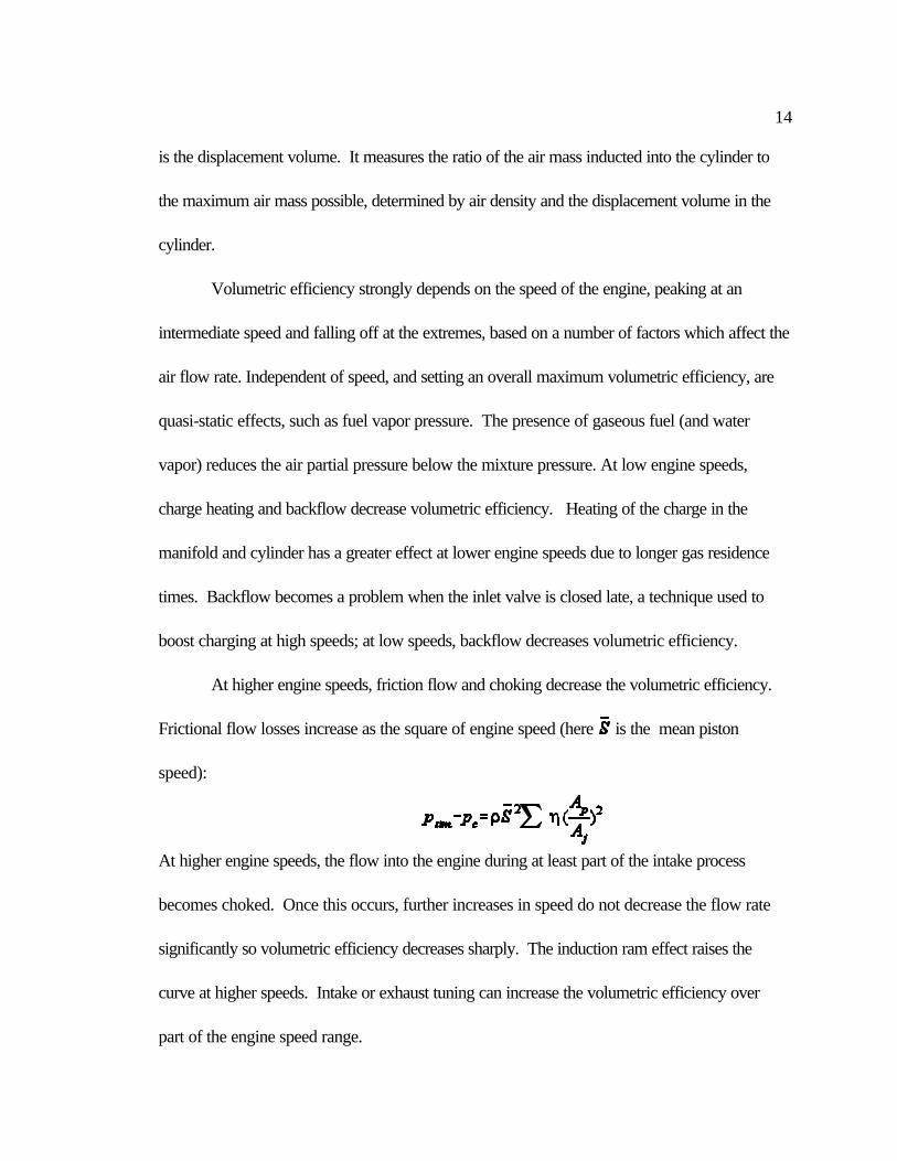
At higher engine speeds, friction flow and choking decrease the volumetric efficiency.
Frictional flow losses increase as the square of engine speed (here is the mean piston
speed):
At higher engine speeds, the flow into the engine during at least part of the intake process
becomes choked. Once this occurs, further increases in speed do not decrease the flow rate
significantly so volumetric efficiency decreases sharply. The induction ram effect raises the
curve at higher speeds. Intake or exhaust tuning can increase the volumetric efficiency over
part of the engine speed range.
15
Heat Transfer
The internal combustion engine operates at extremely high temperatures in the cylinder.
High engine temperatures are necessary to produce high work output. Heat transfer occurs
between the working fluid, the walls of the intake system, combustion chamber, and exhaust
system, and to the coolant. Three modes of heat transfer play a role in the engine: conduction,
convection, and radiation, although radiation is negligible. The magnitude of heat transfer
affects the engine’s specific power and efficiency. As you increase heat transfer per a unit of
fuel, the gas temperatures and pressure in the cylinder decrease, decreasing the work output,
and the fuel efficiency decreases. At lower engine speeds, a longer amount of time elapses per
cycle, allowing greater heat transfer. The relative importance of heat transfer is greatest at low
speeds and loads. If the engine remains at a certain speed, as you lower the load, you decrease
the maximum temperatures in the cylinder, decreasing the work load. The rate of heat transfer
also decreases, but, the relative importance of the heat transfer to the work load increases.
Heat transfer depends on a number of variables, including engine size, equivalence
ratio, speed, load, brake mean effective pressure, spark timing, compression ratio, and
materials. Of these, speed and load have the greatest effect. The peak heat flux in an SI engine
occurs at the mixture equivalence ratio for maximum power N=1.1, and decreases as N is
leaned out or enriched from this value. However, as a fraction of the fuel’s chemical energy,
the heat transfer per cycle is a maximum at N= 1.0 and decreases for richer and leaner
mixtures.
Emissions
16
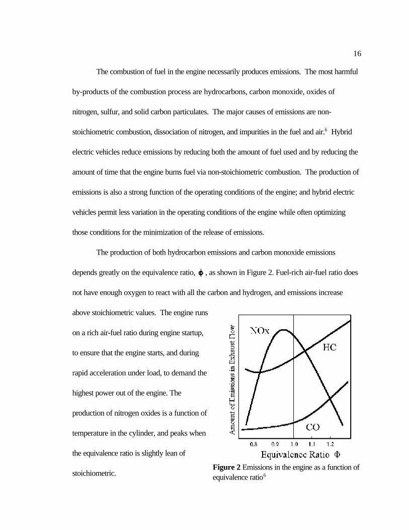
Figure 2 Emissions in the engine as a function ofequivalence ratio6
The combustion of fuel in the engine necessarily produces emissions. The most harmful
by-products of the combustion process are hydrocarbons, carbon monoxide, oxides of
nitrogen, sulfur, and solid carbon particulates. The major causes of emissions are non-
stoichiometric combustion, dissociation of nitrogen, and impurities in the fuel and air.6 Hybrid
electric vehicles reduce emissions by reducing both the amount of fuel used and by reducing the
amount of time that the engine burns fuel via non-stoichiometric combustion. The production of
emissions is also a strong function of the operating conditions of the engine; and hybrid electric
vehicles permit less variation in the operating conditions of the engine while often optimizing
those conditions for the minimization of the release of emissions.
The production of both hydrocarbon emissions and carbon monoxide emissions
depends greatly on the equivalence ratio, , as shown in Figure 2. Fuel-rich air-fuel ratio does
not have enough oxygen to react with all the carbon and hydrogen, and emissions increase
above stoichiometric values. The engine runs
on a rich air-fuel ratio during engine startup,
to ensure that the engine starts, and during
rapid acceleration under load, to demand the
highest power out of the engine. The
production of nitrogen oxides is a function of
temperature in the cylinder, and peaks when
the equivalence ratio is slightly lean of
stoichiometric.
17
Variation of the equivalence ratio facilitates the engine’s successful performance under
numerous operating conditions. For power operation at wide-open-throttle, increasing the
equivalence ratio gives maximum power. For idling and low engine speeds, when the throttle is
mostly closed, a large exhaust residual is created, which leads to poor combustion. Making the
fuel-air ratio richer helps to compensate. Start-up of a cold engine demands a very high air-fuel
ratio to ensure that there will be enough fuel vapor for combustion. This is a large source of
emissions.
Electric Motors 8,9
Electric motors demonstrate a number of features that are desirable for application to
personal transportation. Electric motors have a very high drivetrain efficiency, at least 90%.
They also produce high torque at low speeds, a feature which has many applications in the
varied driving conditions and need for quick acceleration of personal transportation.
Early electric vehicles and hybrid electric vehicles employed dc motors, but these are
rarely used anymore. Now, hybrid electric vehicles most frequently employ polyphase ac
motors, because of the several advantages they offer over dc motors, such as 1) they operate
without a commutator, and so require virtually no maintenance, 2) they are relatively small and
light in weight, for a given voltage, power and speed rating. 3) they are less expensive.7 Of
these, the permanent magnet synchronous motor and the ac induction motor are most frequently
used. As batteries provide only dc current, the use of ac motors requires a system to convert
dc current to ac current, a system of controls.

18
Electric motors operate on three fundamental laws of electromagnetism: Ampere’s
circuit law, Ampere’s force law, and Faraday’s law. Ampere’s circuit law relates a current to
the magnetic field it creates,
r rH dl∫ ⋅
where H is the magnetic field, dl is an element of length, and I is the current passing through the
bounded area. It is integrated over the path. The magnetic field circles around the current.
Ampere’s force law states,
where f is the vector force per unit length on the wire, I is the current in the wire, and B is the
vector flux density due to I. Faraday’s law describes the emf produced by changing flux. It is
as follows:
where v is the total induced voltage in the coil, n is the number of turns in the coil, is the
time-varying magnetic flux.
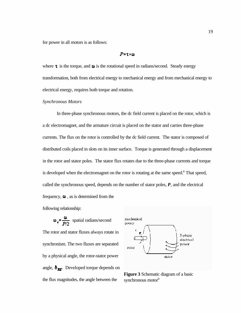
All electric motors are made of a stator, which does not rotate, and a rotor, which can
rotate, and an air gap between them to permit motion. They are composed of two circuits, the
field circuit, whose current produces the magnetic flux in the motor, and the armature circuit,
that carries the current from the battery. Depending on the type of motor, the field circuit can
be on either the rotor or the stator, and the armature is always on the opposite. Power is
created in the motor by the interaction of the magnetic flux and the current; the basic equation
19
Figure 3 Schematic diagram of a basicsynchronous motor9
for power in all motors is as follows:
where is the torque, and is the rotational speed in radians/second. Steady energy
transformation, both from electrical energy to mechanical energy and from mechanical energy to
electrical energy, requires both torque and rotation.
Synchronous Motors
In three-phase synchronous motors, the dc field current is placed on the rotor, which is
a dc electromagnet, and the armature circuit is placed on the stator and carries three-phase
currents. The flux on the rotor is controlled by the dc field current. The stator is composed of
distributed coils placed in slots on its inner surface. Torque is generated through a displacement
in the rotor and stator poles. The stator flux rotates due to the three-phase currents and torque
is developed when the electromagnet on the rotor is rotating at the same speed.8 That speed,
called the synchronous speed, depends on the number of stator poles, P, and the electrical
frequency, , as is determined from the
following relationship:
spatial radians/second
The rotor and stator fluxes always rotate in
synchronism. The two fluxes are separated
by a physical angle, the rotor-stator power
angle, . Developed torque depends on
the flux magnitudes, the angle between the
20
fluxes, and the geometry of the machine:
where R, l, and g are the air-gap radius, length, and width respectively. The general equation
for a rotating flux wave is
where is the magnetic flux on the rotor, P is the number of poles, is the angle of
maximum total flux density, and is the position of the flux maximum at t=0.
The synchronous motor has no starting torque, as it requires that the rotor and stator
both be rotating at synchronous speed in order to produce torque. Although this seems like a
major limitation of synchronous motors, this problem can be eliminated by adding circuitry to
cause the excitation of the windings to advance in step with the rotor. Use of this technique
with a synchronous motor creates the electronically commutated motor.
The synchronous machine also also functions as a generator. An external mechanical
drive provides torque to the rotor, and a dc field current must be kept on the rotor. The
electrical frequency is determined by the speed of the mechanical drive:
and the voltage of the generated power is controlled in part by the field current.
A synchronous motor runs at very high efficiencies, and has only one major source of
losses The power supplied to the dc field circuit supplies relatively small resistive losses in the
field winding. When running as a motor, all of the input electrical power, minus the ohmic
losses in the field winding, is transformed into mechanical power. Similarly, when running as a
21
generator, all of the mechanical power is transformed into electrical power except the power to
resistive losses in the field winding. This results in a very high efficiency:
The losses are very small compared to the input power, so usually has a value in the 90th
percentile.
AC Induction Motors
In induction motors, the field circuit is on the stator, the armature circuit is on the rotor,
and the rotor poles are induced by transformer action. Both the stator poles and the rotor
poles rotate at synchronous speed, but the rotor rotates physically at a speed slightly less than
synchronous speed and slows down as the load torque and power requirements increase.
The stator is identical to a stator of a synchronous machine: three phases, P poles,
sinusoidal mmf and flux distribution, and synchronous speed. In induction motors, the stator
carries the field. The rotor is much different; in induction motors, the rotor is an iron cylinder
with large embedded conductors, which are shorted to allow the free flow of current. The
stator flux induces an ac current in the each of the rotor conductors, and an ac voltage is
induced in the rotor to drive the currents. The currents in the conductor produce a magnetic
flux, , and combined with the stator flux, , they produce a third flux, , a rotor-stator
flux, which produces the developed torque, which opposes the torque used to cause rotation.
The developed torque, , is proportional to the induced currents and the sine of the power
angle, and hence varies with slip speed, , the angular velocity in the negative direction of the
rotor conductors relative to the stator flux.
22
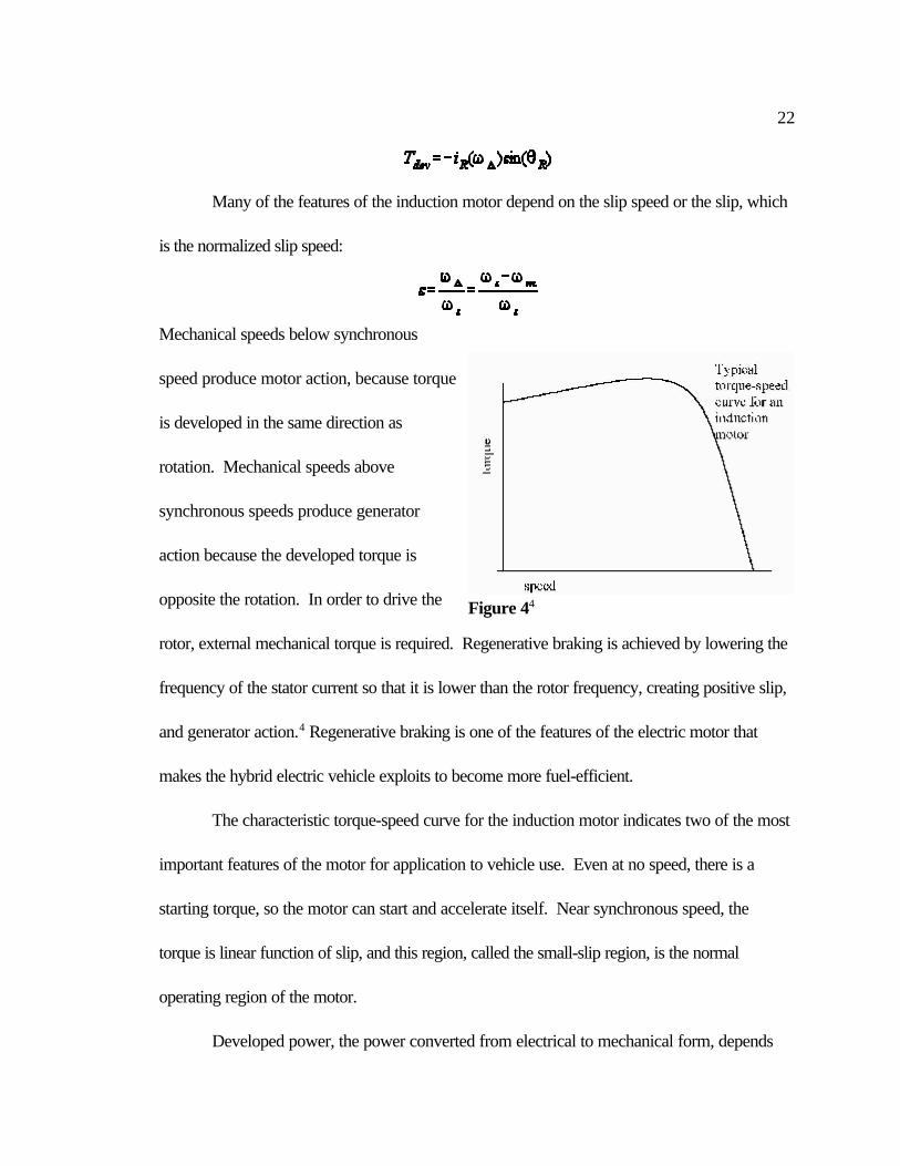
Figure 44
Many of the features of the induction motor depend on the slip speed or the slip, which
is the normalized slip speed:
Mechanical speeds below synchronous
speed produce motor action, because torque
is developed in the same direction as
rotation. Mechanical speeds above
synchronous speeds produce generator
action because the developed torque is
opposite the rotation. In order to drive the
rotor, external mechanical torque is required. Regenerative braking is achieved by lowering the
frequency of the stator current so that it is lower than the rotor frequency, creating positive slip,
and generator action.4 Regenerative braking is one of the features of the electric motor that
makes the hybrid electric vehicle exploits to become more fuel-efficient.
The characteristic torque-speed curve for the induction motor indicates two of the most
important features of the motor for application to vehicle use. Even at no speed, there is a
starting torque, so the motor can start and accelerate itself. Near synchronous speed, the
torque is linear function of slip, and this region, called the small-slip region, is the normal
operating region of the motor.
Developed power, the power converted from electrical to mechanical form, depends
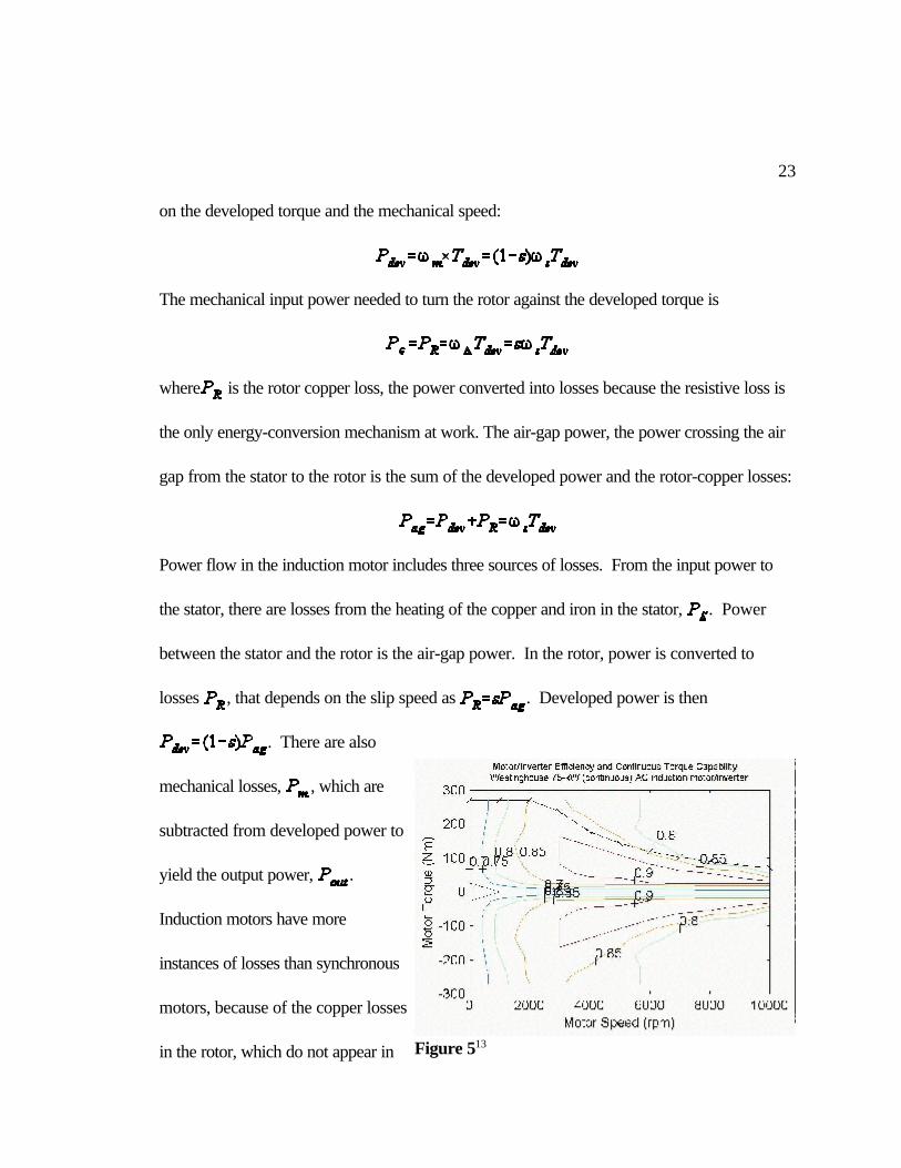
23
Figure 513
on the developed torque and the mechanical speed:
The mechanical input power needed to turn the rotor against the developed torque is
where is the rotor copper loss, the power converted into losses because the resistive loss is
the only energy-conversion mechanism at work. The air-gap power, the power crossing the air
gap from the stator to the rotor is the sum of the developed power and the rotor-copper losses:
Power flow in the induction motor includes three sources of losses. From the input power to
the stator, there are losses from the heating of the copper and iron in the stator, . Power
between the stator and the rotor is the air-gap power. In the rotor, power is converted to
losses , that depends on the slip speed as . Developed power is then
. There are also
mechanical losses, , which are
subtracted from developed power to
yield the output power, .
Induction motors have more
instances of losses than synchronous
motors, because of the copper losses
in the rotor, which do not appear in

24
synchronous motors. The efficiency of induction motors is as follows:
Even though the induction motor has more sources of losses than the synchronous motor, the
efficiency is still quite high.
Motor Control
Electronic control of motors is essential for their application to vehicle use for primary
reasons: 1) the motor must be matched to the varying load demands of vehicular operation, and
2) most motors employed in the vehicles will run off ac current, but battery current is dc,
requiring a device to transform alternating current to dc current. The advent of solid-state
devices, specifically the transistor, the silicon-controlled rectifier (SCR), and gate-turnoff
thrysistors led to the re-emergence of electric vehicles in the 1970's5. They provided the
rugged and reliable power control needed for vehicles.
Synchronous machines always run at synchronous speed, which is determined by the
electrical frequency and the number of poles. Both the rotor and the stator fluxes rotate at this
same speed. The only way to vary the synchronous speed is to vary the frequency of the
excitation of the stator windings.
The induction motor is not a constant-speed machine as the synchronous motor is. The
speed of the rotor must be less than the speed of the stator, synchronous speed, in order to
develop a torque. The speed varies with the load on the rotor; speed decreases as the load
increases. Speed can also be varied by varying the frequency of the stator excitation. In both,
25
Figure 6 Pulse-width modulation in an inverter12
torque can be increased by increasing the amplitude of the current.
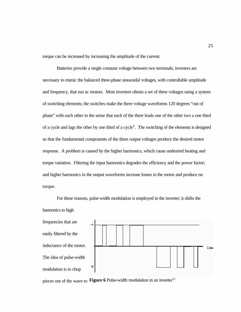
Batteries provide a single constant voltage between two terminals; inverters are
necessary to mimic the balanced three-phase sinusoidal voltages, with controllable amplitude
and frequency, that run ac motors. Most inverters obtain a set of three voltages using a system
of switching elements; the switches make the three voltage waveforms 120 degrees “out of
phase” with each other in the sense that each of the three leads one of the other two a one third
of a cycle and lags the other by one third of a cycle6. The switching of the elements is designed
so that the fundamental components of the three output voltages produce the desired motor
response. A problem is caused by the higher harmonics, which cause undesired heating and
torque variation. Filtering the input harmonics degrades the efficiency and the power factor;
and higher harmonics in the output waveforms increase losses in the motor and produce no
torque.
For these reasons, pulse-width modulation is employed in the inverter; it shifts the
harmonics to high
frequencies that are
easily filtered by the
inductance of the motor.
The idea of pulse-width
modulation is to chop
pieces out of the wave to

26
Figure 7 Schematic diagram of a generic parallel controlsystem4
control the fundamental in the output. The width of each conduction interval is equal to a large
fraction of the repetition period.7
It is also important to regulate the current. As voltage slips below the rated voltage,
current can increase significantly, causing magnetic saturation. Motor controllers thus vary
applied voltage in proportion to frequency to keep the current roughly constant; this is called
constant volts/hertz drive.
A Generic Control Strategy
Hybrid electric vehicles attempt to capitalize on the complementary characteristics of
the internal combustion engine and the electric motor in order to minimize fuel consumption and
the production of emissions. There are numerous ways to configure the system and strategize
the control system. The following is a generic control strategy. It is chosen both for its
characteristics of minimal fuel
consumption and emissions
production, and because this system
can make the HEV perform in a
very similar manner to the traditional
car, an important reason for
widespread acceptability in the
consumer market.
Figure 7 shows the
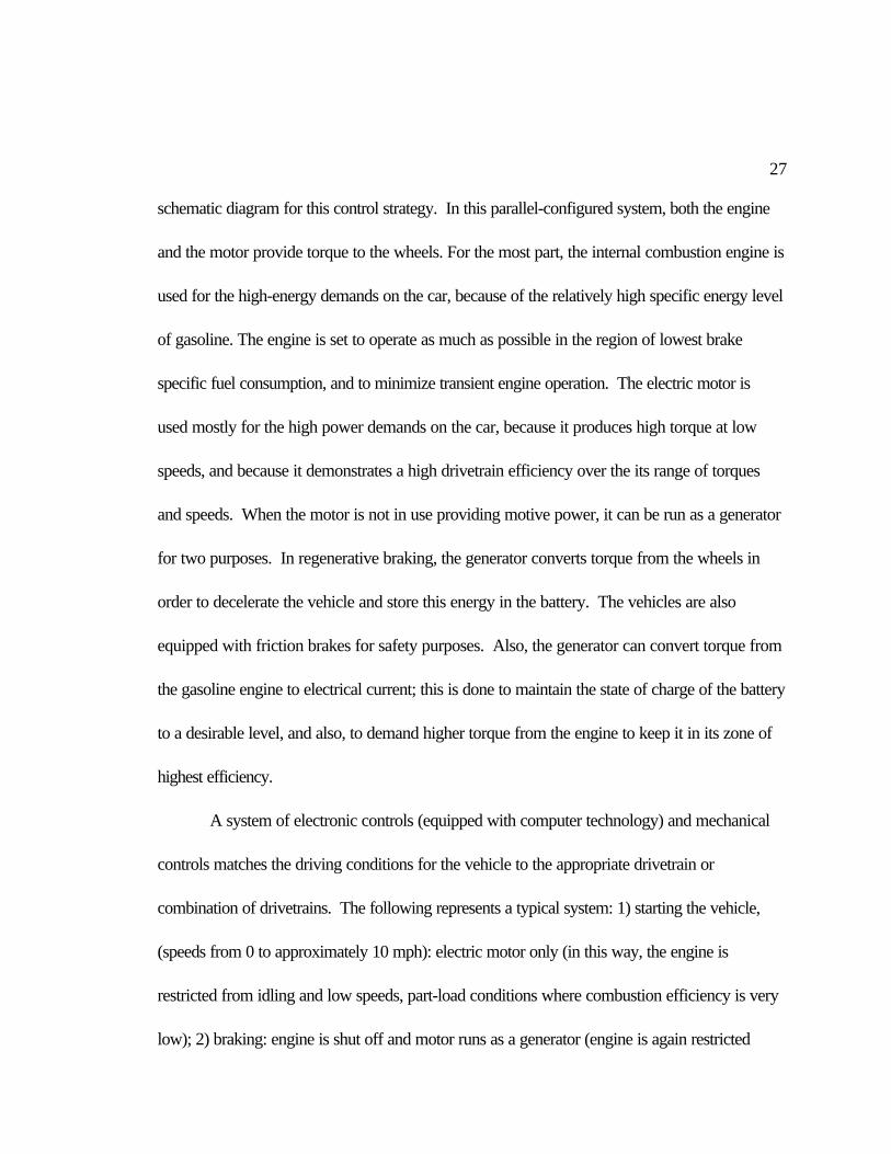
27
schematic diagram for this control strategy. In this parallel-configured system, both the engine
and the motor provide torque to the wheels. For the most part, the internal combustion engine is
used for the high-energy demands on the car, because of the relatively high specific energy level
of gasoline. The engine is set to operate as much as possible in the region of lowest brake
specific fuel consumption, and to minimize transient engine operation. The electric motor is
used mostly for the high power demands on the car, because it produces high torque at low
speeds, and because it demonstrates a high drivetrain efficiency over the its range of torques
and speeds. When the motor is not in use providing motive power, it can be run as a generator
for two purposes. In regenerative braking, the generator converts torque from the wheels in
order to decelerate the vehicle and store this energy in the battery. The vehicles are also
equipped with friction brakes for safety purposes. Also, the generator can convert torque from
the gasoline engine to electrical current; this is done to maintain the state of charge of the battery
to a desirable level, and also, to demand higher torque from the engine to keep it in its zone of
highest efficiency.
A system of electronic controls (equipped with computer technology) and mechanical
controls matches the driving conditions for the vehicle to the appropriate drivetrain or
combination of drivetrains. The following represents a typical system: 1) starting the vehicle,
(speeds from 0 to approximately 10 mph): electric motor only (in this way, the engine is
restricted from idling and low speeds, part-load conditions where combustion efficiency is very
low); 2) braking: engine is shut off and motor runs as a generator (engine is again restricted
28
from idling, and energy is recaptured and stored that would be wasted in a vehicle without
regenerative braking capacity); 3) cruising conditions: engine only; 4) rapid acceleration and
climbing hills: engine and motor together to account for elevated power demands. In this
fashion, hybrid electric vehicles have been shown to double fuel economy over a comparable
traditional automobile and halve the production of emissions.
No universal control strategy is in use. The design of HEVs permits great flexibility,
allowing the designers to optimize for a number of different benefits, such as fuel economy,
emissions, cost of the vehicle, and safety. Comparison of the three HEV concept cars
produced by the automobile manufacturers and displayed at the January, 2000 Detroit Auto
Show reveals this large variability in design. In the GM Precept, the electric motor powers the
front wheels and the gasoline engine powers the rear wheels. Toyota employs the “Prius Hybrid
System” using a continuously variable transmission, and both an electric motor and a separate
generator. Hybrids could be programmed to learn the driving patterns of its owner and adjust to
them for maximum improvements in emissions and fuel economy11. A number of other systems
are possible.
Conclusion
HEVs capitalize on the complementary characteristics of the gasoline engine and the
electric motor. Hybridization of the drivetrain combines the high efficiency of the electric motor
with the high energy density of gasoline. The HEV eliminates the idling of the engine and aims to
run the engine only in the island of minimum brake specific fuel consumption. The HEV also

29
prevents the engine from operating at transient conditions. The electric motor demonstrates
high torque at low speeds, a characteristic that makes it suitable to the variable conditions of
driving, and allows it to provide power efficiently. In a parallel-configured hybrid, the most
common configuration of the system, either the gasoline engine, the electric motor, or both can
provide torque directly to the wheels. A system of mechanical and electrical controls matches
the drivetrain to the driving conditions. This method has been shown to halve the consumption
of fuel and the production of emissions.
Although HEVs are not zero-emission vehicles, but still produce emissions and
consume gasoline, the remarkable improvements in emissions and fuel consumption that they
demonstrate will secure them a solid position on the road to more environmentally friendly
vehicles. HEV technology is the most advanced and developed out of the group of personal
transportation technology that is in the works. Many people expect that hydrogen fuel cell
technology will eventually become the best choice for environmentally friendly personal
transportation, but much research lies ahead before that can happen. HEVs are the most likely
technology to appear and make a large impact on the consumer market.
30
Appendix: The Article
Preface
This article translates the scientific treatment of the principles explained above into the
language of the non-scientific and less technical. The article is nonetheless scientifically
accurate. It’s audience is the non-scientific adult community. A generic HEV is described,
with parallel configuration, and with the performance modeled on the conventional car; this is
the type of HEV I consider the most likely to mass-produced.
A Lesson in the Physics of Hybrid Electric Vehicles
Half gas, half electric, half fuel use, half the emissions: the remarkable
characteristics of the brand-new hybrid-electric car.
But is it really brand-new? The car as we know it was not necessarily a shoo-in to be
our car. At the turn of the last century, engineers were racing to develop a personal
transportation vehicle to replace the horse-and-buggy, and a number of ideas were in the air.
Three major types of these horseless vehicles were in the race: the gasoline-engine vehicle, the
electric vehicle, and the steam-powered vehicle. For a number of years they were
neck-to-neck, each with its own particular advantages and disadvantages. Even then, the
electric vehicle suffered from the familiar problem of a much shorter range than the other two
cars. And even then, a number of engineers built hybrid-electric cars to combine the high
efficiency of the electric motor with the large energy-storage capacity of gasoline, extending the
31
range of the electric and making the entire vehicle more energy-efficient. The first one appeared
in Philadelphia as early as 1897. These hybrids offered their own particular advantage - one
that we’ve since outgrown. In the days of the cranky and difficult internal combustion engines,
and reliable electric motors, hybrids boasted a security measure - if you were out on a trip, and
the engine stalled or refused to start, you could rely on the trusty electric motor to get you
home!
The idea to incorporate both gasoline and electric under one hood is no 20th century
innovation - rather, it is a rediscovery of a century-old concept. What urged us to this
rediscovery? Design strategies during the last few decades have increasingly been influenced
by environmental considerations, specifically, the need to reduce the engine’s contribution to air
pollution, and the need to reduce automotive fuel consumption7. An electric car - which neither
releases emissions nor consumes gasoline - is often touted as the answer; but its perennial
weakness obstructs the path to wide acceptance: limited range. It renders the car too
inconvenient for most people - we need a car that can make long trips. This recalls the line of
thinking that led to the first hybrid electric, and so it leads today’s car manufacturers to the
same conclusion.
Everyone knows that the gasoline engine won that early race, and people began to
forget that there had ever been any competition. Why did it win? It was not that it was any
faster than the others. Gasoline is a very potent fuel, storing large amounts of energy in a
relatively lightweight package. However, the engine was only about 20% efficient in converting
32
this energy to the energy of motion. An electric motor is about 90% efficient is converting the
energy in batteries to mechanical energy. Choosing the gasoline engine was a choice of high
energy over high efficiency. Gasoline had become widely available and relatively cheap - it was
common enough and cheap enough to justify the engine’s inefficient conversion10. With the
enormous number of cars the earth now supports (around 600 million) the validity of this reason
has expired - since gasoline is a non-renewable energy source, the low efficiency of the engine
is no longer dismissible. So if one of the major reasons why we originally chose the
gasoline-powered vehicle no longer applies, perhaps we should be urged towards a new
choice.
The first HEV derived from a perceptive observation about the choice between the
gasoline vehicle and the electric vehicle: the two complement each other. The benefits of the
electric motor include zero emissions and high efficiency of converting energy into motion.
However, present battery technology limits the range of pure electric vehicles - even massive
batteries store relatively little energy. The strengths of the gasoline engine include the high
energy density of gasoline (300 to 400 times that of batteries), the resulting longer range, the
extensive infrastructure supporting it, and the whole century of development that has rendered it
refined and reliable. But fossil fuels are both a blessing and a curse; although they were the
preferred energy source for the 20thcentury, they cannot continue to predominate. There are
two environmental limiting factors: the production of greenhouse gases and the recognition that
fossil fuels are a non-renewable resource.
33
In an HEV, either the gasoline engine or the electric motor can be used to provide
power to the wheels directly, allowing the car to match the driving conditions to the most
suitable source of energy, either the gasoline engine, or the electric motor, or both. So, the
HEV uses the gasoline engine for the high-energy demands of cruising and long trips. It uses the
electric motor for high-power conditions of starting, accelerating, and climbing hills. And, in the
meantime, the HEV halves the consumption of fuel and the production of emissions.
Half Gasoline
In order to understand how the HEV works, it is necessary to examine each of the
components in a little more detail. An engine converts chemical energy stored in the fuel to the
mechanical energy of driving. Gasoline is combustible: in the presence of oxygen, it reacts with
it, breaking down into a number of different, smaller compounds, and releasing the energy of
the bonds. This energy takes the form of pressure and heat. The smaller compounds are the
exhaust gases; and the energy is transferred by the engine into mechanical work.
The engine capitalizes on a fundamental physical principle: the equivalence of heat and
work. Both are different forms of energy. The engine takes a large amount of heat, produced
by the combustion of gasoline, and produces useful work - mechanical movement. An
automobile engine creates this work through the movement of a piston within a cylinder. For
the spark-ignition engine, the piston sweeps down the cylinder, and air and fuel follow the
piston into the cylinder. Next, the piston moves up the cylinder, compressing the fuel-air
mixture, raising its pressure and temperature. This makes the mixture easier to combust. Next,
34
combustion: the spark-plugs send a spark through the mixture, igniting it. This explosion pushes
the piston down the cylinder. This movement creates the work of the engine: the piston is
attached to the crankshaft, which transfers this movement to the wheels. Lastly, the piston
moves back up the cylinder, pushing the exhaust gases out of the cylinder. That completes the
cycle. Since the piston has moved through the cylinder four times during the cycle, it is often
called a four-stroke cycle. In a diesel engine, the cycle is a little different, but the principles of
combustion are the same.
Any use of the engine brings along inefficiencies much greater than those in the electric
motor. The laws of physics place a strict upper limit on the efficiency of the engine - there will
never be an engine as efficient as the electric motor, for nature denies it. This is not a problem
to be fixed by clever engineering. An engine converts heat that came from the combustion of
gasoline to work to move the car forward, relying on the equivalence of heat and work. But the
2nd law of thermodynamics limits the quantity of heat that can be converted to work, and this
maximum hovers at around only 50%. Even an ideal engine can only produce half the amount
of work from a larger amount of heat. Any time you fill up the tank, about half the energy
stored in that gasoline can never be used to drive the car - half of the energy is inaccessible
because of the 2nd law! There is no way around it. Electric energy does not have such
restraints - a major reason to move away from heat engines.
A consumer, looking for a new car, notices one thing about fuel economy immediately:
every car on the market advertises two numbers for fuel economy, not one. Urban driving gets
35
Fuel consumption graph for an engine. Note theisland of minimum fuel consumption.
the lower of the two numbers, and highway driving gets a higher number. It is a universal: every
single car on the market has two different figures for these driving conditions, and urban driving
is always lower. Traffic jams, lights, pedestrians, and road-work characterize the choppy
motion of urban driving. This “stop and go” driving has lower fuel economy partially because of
the large amount of time that the engine idles. Whenever the engine is not producing power,
such as when the car is stopped or during braking, it is still running and using fuel, essentially
wasting it. In fact, braking acts as a double culprit. If the purpose of the engine is to convert
fuel energy (stored in the gasoline) to mechanical energy (the energy of movement), then
braking, by its very purpose of slowing the car, subverts that purpose. In braking the energy of
forward motion of the car is dissipated as heat in the brake pads. All this time, too, fuel is
added to the engine to keep it running.
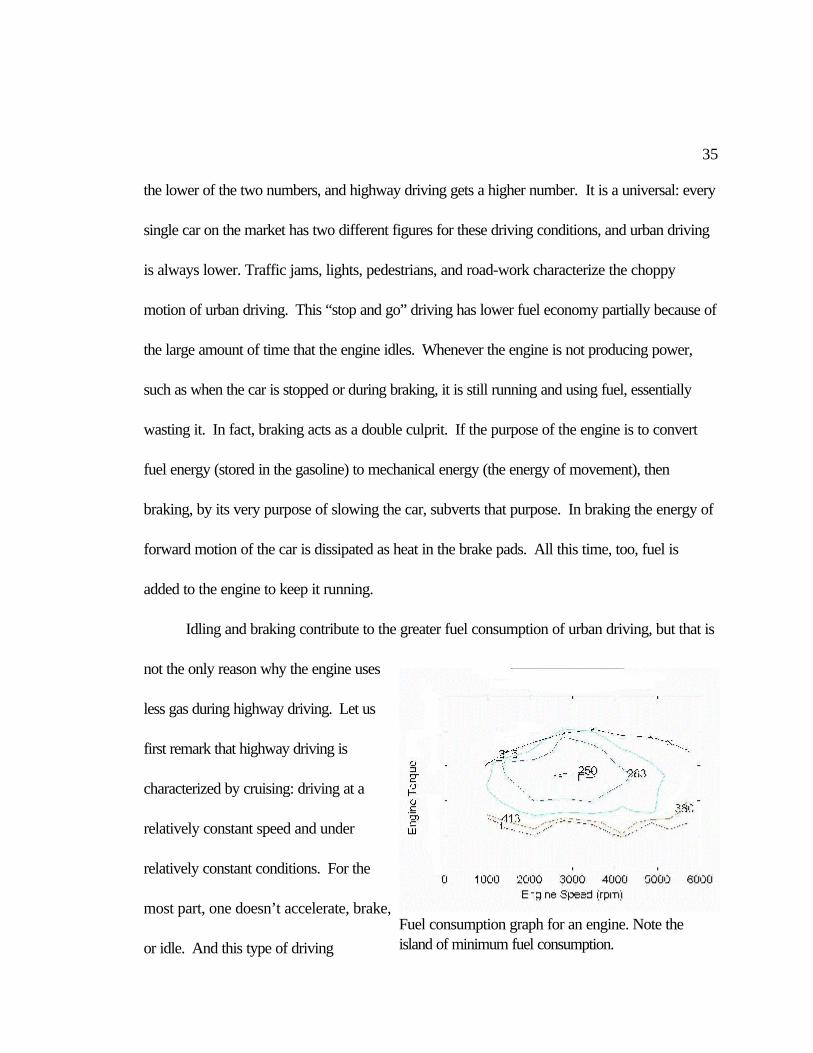
Idling and braking contribute to the greater fuel consumption of urban driving, but that is
not the only reason why the engine uses
less gas during highway driving. Let us
first remark that highway driving is
characterized by cruising: driving at a
relatively constant speed and under
relatively constant conditions. For the
most part, one doesn’t accelerate, brake,
or idle. And this type of driving
36
maximizes the engine’s fuel efficiency - the engine is designed to be most efficient on the
highway. The graph depicts the fuel consumption contours over the ranges of the engine’s
speed and load - notice that the region of lowest fuel consumption is a very distinct and small
region, “an island,” within the entire range of the engine’s operation. Furthermore, straying from
this region causes dramatic increases in fuel consumption. Thus the engine performs its job
most efficiently only under specific conditions of speed and load, which correspond to cruising
on the highway.
A peek under the hood reveals that the actual engine is a maze of pipes, wires, and
steel: all these mysterious pieces don’t relate well to the relative simplicity of the basic principles
of the engine. But the engine must also facilitate its own operation: it must have valves and
manifold for the air to enter the cylinder and for the exhaust to exit; it must have a similar system
for gasoline to enter, it must have a cooling system to keep the engine at functional
temperatures, and it must have a system for lubricating all of the moving parts. Although the
basic principle of the engine is relatively simple, the actual design of the engine is tortuously
complicated. And all of these systems bring along their own inefficiencies - a fact that limits the
engine to a small region of speed and load where it can be the most efficient. For example, the
intake manifold, the engine system that provides the air into the cylinder, tries to fill each
cylinder completely with air for each cycle of the engine. If it provides less air than the
maximum, less fuel can combust. But when a lot of power is demanded from the engine, not
enough air can move quickly enough through all the pipes, and the engine gasps for more air
37
than it can get. In this case, not all of the fuel burns, and the engine’s efficiency is lower.
Friction of all of the moving parts in the engine, and transfer of heat to the cooling systems, like
the fan and the radiator, also decrease greatly the efficiency of the car.
Even some of the engineers building the earliest gasoline-powered cars, (those with
sensitive noses) recognized a major drawback of their engines. In Detroit, in 1897, an engineer
named Barton Peck commented about his car, “There is one great obstacle that must be
overcome and this is the offensive odor from gasoline that has been burned and is discharged
into the air. It is a sickening odor and I can readily see that should there be any number of them
running on the street, there would be an ordinance passed forbidding them10.” Mr. Peck’s
prediction of a law banning cars fell through - now the world has 600 million of them - but his
observation on exhaust was full of foresight. Emissions from the world’s swelling fleet of cars
causes environmental problems such as urban air pollution and global warming - and this is the
major force in favor of electric cars. A pure electric has no tailpipe, visual evidence that it
releases no emissions. (Electric cars are not completely innocent - if the initial source of their
electricity is a fossil fuel burning electric plant, then some emissions are released into the
atmosphere. These are usually of less concern, though, because of the higher pollution controls
at power plants.)
Any combustion of fossil fuels leads to the production of emissions. But, not all types
of combustion are created equal. Different levels of emissions are created depending on the
ratio of gasoline to air that is used for combustion. Most of the time, the engine runs lean, with a
38
little more air then is necessary, because this is more fuel-efficient and creates a smaller amount
of emissions. But lean-running engines do not get the most power out of the engine. Pressing
down hard on the gas pedal to accelerate forces extra gasoline into the cylinder, speeds up the
engine, and gets more work out of it. It also bumps it out of the island of minimum fuel
consumption. Accelerating adds more gasoline to the engine than there is air, using a fuel-rich
mixture in which there is not enough air to react with all of the gasoline, and not all of it the
gasoline combusts. For acceleration, this tactic increases the power output of the engine.
Fuel-rich mixtures also coax the engine into turning over when it might want to stall, for
example, when it is first starting up or when it must suddenly do much more work. Any sort of
transient engine condition (when the demands on the engine are changing) or high-power
demand on the engine requires a fuel-rich mixture. And fuel-rich mixtures simultaneously waste
fuel and increase emissions! Any fuel that does not burn is vaporized and released in the
exhaust. This is one of the greatest sources of emissions in the car.
Half Electric
The other major component of an HEV is an electric motor. The idea to use electric
power for personal transportation dates back 120 years - and an electric vehicle (a man-sized
tricycle powered by a motor)10 predated the first gasoline vehicles. Today, this idea seems
new, but it is altogether logical. Electricity and electric motors take part inextricably in daily life
- an attempt to imagine life without electricity conjures images of barbarians, wood stoves, and
candlelight. With the advent of electric power came innumerable and clever ways to use it.
39
Electric motors, which convert electrical energy to mechanical energy, the energy of movement,
supply much of our need for mechanical energy. Electric fans, stereos, hair dryers, vacuum
cleaners (and endless others) all rely on electric motors. They have a relatively simple design,
are enormously common, and well-understood. Since the dawn of the electric age, engineers
have been striving to apply the success of the electric motor to personal transportation.
A formidable obstacle has thus far succeeded in thwarting their hopes. Electric vehicles
have a limited range - a problem of batteries, not of motors. Detached, thankfully, from the
mains, electric cars must store the electric energy they require onboard, in their batteries. But
the batteries we know and use cannot store enough energy for most people’s transportation
needs. That is a separate issue. The viability of the electric motor for personal transportation
becomes clear when the problem of batteries can be bypasses, as in the HEV, which does not
rely solely on batteries for energy storage.
The function of the gasoline engine is to convert chemical energy to mechanical energy.
Similarly, an electric motor converts electrical energy (from an electric current) to mechanical
energy. Although these are similar functions, the actual process is very different. An electric
motor is more simple, fundamental, and elegant than an engine. The electric motor runs at
about 90% efficiency, wasting very little energy. Furthermore, this high efficiency is
characteristic of the motor over the entire range of vehicle operations - a large contrast to the
gasoline engine.
The concept for the motor developed from an observation by an English scientist,
40
Michael Faraday. He discovered the fundamental connection between electricity, magnetism,
and force through an experiment involving a current-carrying wire, magnets, and a beaker full of
mercury. With the wire running down the middle of the beaker, and the magnet placed
alongside the wire in the beaker, the magnet revolved continuously around the wire, sweeping a
circular path through the mercury. Why? This mysterious movement stems from a physical
principle that links these three seemingly distinct physical processes: electricity, magnetism, and
movement. The presence of electrical current moving in one direction, plus a magnetic field
perpendicular to the current, causes a force that acts perpendicular to both of them, the force
which caused the magnet to revolve around the wire. The electric motor capitalizes on this
principle. For a car, this is the mechanical energy which can then be used to drive the wheels
and propel the car.
Electric motors have a remarkable characteristic - they are able to produce high torque
even at low speeds. That means that electric motors can turn the car’s axle quite powerfully
even when they are just starting. They do not have be turning over very quickly in order to
produce torque - in fact, they do not have to be turning over at all. Simply sending current
through a still motor starts it, almost immediately, to produce high torque. Even our present cars
take advantage of this trait - in the electric starter. The electric starter employs a motor to drive
the engine through the first low-speed revolutions, because the engine can’t start itself. Thus, in
a manner of speaking, the electric starter turns every conventional car into an HEV! The
electric motor not only starts itself, it can also produce high torque soon thereafter, making it
41
well suited to the demands of vehicle acceleration.
No engine can start with exhaust gases and convert them back to gasoline and
oxygen. If that were true, the world’s problems with both energy supply and air pollution would
be solved immediately! No engine works backwards - but an electric motor can. It works
backwards, as a generator, taking the energy of movement and returning it to electrical energy
in a current. Faraday’s experiment could have easily worked in reverse. If he had turned off
the current in the wire, making the magnet stop revolving around it, grabbed hold of the magnet
and stirred it around in the opposite direction, this would have caused a current to flow down
the wire, towards the battery, charging it! Here, mechanical energy generates electrical energy.
The presence of an electric motor in the car transforms the nature of braking from the
dissipation of energy to regenerative braking - braking that regenerates current to be stored in
the batteries. The same energy can later be used to accelerate the car. This feature greatly
enhances the efficiency of the car during urban driving with its many stops and starts. It is a
feature of electric motors, and therefore applicable to all electric cars, including HEVs.
The Hybrid Electric Vehicle
A hybrid electric vehicle (HEV) is intelligent. Not only does it balance an electric
motor and a gasoline engine, but it manages to use a minimum amount of fuel and release a
minimum amount of emissions. (And it does all of this without any effort on the part of the
driver). The HEV can turn the engine and the motor on and off, as long as one of them is
powering the car. When the engine is on, it runs, as much as possible, in its island of minimum
42
fuel consumption, getting as much energy as possible out of the gasoline. If not all of the energy
is needed to drive the car, some of it can be stored in the battery, and saved for later. The HEV
never lets the engine idle - at a stop light for instance - it just turns it off. The car runs electric
for starting, for slow-speeds, and for high-power needs, like rapid accelerating or climbing
steep hills. The electric motor is well suited to these applications, whereas the engine would use
up the most fuel and release the most emissions during high-power operations. Smart! This is
the key to the success of the HEV in reducing fuel consumption and emissions over a traditional
car. Having identified that these high-power operations cause the majority of emissions and
wasted fuel, the HEV prevents the engine from operating in these situations, turns on the motor,
and consequently eliminates the greatest chunk of emissions - wasted fuel!
An HEV intelligently gets around the individual problems associated with the gasoline
engine and the electric vehicle. It diminishes the production of emissions and the use of
fuel. The problem of batteries for the electric vehicle is conquered. An HEV charges itself - it
never has to be plugged in. When not in use providing power, the motor can run as a generator
to transfer energy from regenerative braking and from the gasoline engine to the batteries. The
only recharging necessary is refueling by going to the gas station. Also, there is not the same
demand on the batteries as there would be in an electric vehicle, where the batteries must store
all the energy the car needs. These batteries are smaller, and only have to be able to provide
for the high-power uses. Similarly, the engine for a HEV is smaller than it would be in a
traditional car, as it doesn’t have to provide as much horsepower. (Again, this makes it more

43
fuel-efficient - most engines are too big for most of their uses.)
So, in the year 2000, we are waiting for the introduction of hybrids into the mainstream
automobile market. It’s now more than a century after the first HEV was built in Philadelphia.
That car had an unfortunate fate. On its first trip, its designer got out of the car, and caught his
foot on one of the wires. This sent an arc of electric current through the gas tank, igniting all the
gas, and the first HEV was engulfed in flames! Do not take this as a sign! That disappointed
engineer lacked technology that has since been developed to carefully control electric currents
and voltages. Modern HEVs rely on this technology and the computer technology that
intelligently controls all of the different elements of the HEV to produce its remarkable results.
The HEV is the environmentally friendly car of the near future.
44
1. PNGV Program Plan, 1995. www.ta.doc.gov/pngv/goals/pp_c5.htm
2. Hayashida, M. et al. “Study on Series Hybrid Electric Commuter-Car Concept” SAE paper970197
3. Merriman, C. et al. “The Effects of Engine Performance and Engine Starts on Series HEVOperation.” SAE paper 970288.
4. Cuddy, Matthew R. and Keith B. Wipke. “Analysis of the Fuel Economy Benefit of Drivetrain Hybridization.” SAE paper 970289
5. Anderson, C. and E. Pettit. “The Effects of APU Characteristics on the Design of Hybrid Control Strategies for Hybrid Electric Vehicles.” SAE paper No. 950493
6. Pulkabek, Willard W. Engineering Fundamentals of the Internal Combustion Engine.
7. Heywood, J. B. Internal Combustion Engine Fundamentals New York: McGraw-Hill1988.
8. Murphy, G. J. “Three-Phase Induction Motors and Controls for Electric Cars.” Appendix B. in Wakefield, Ernest H. The History of the Electric Vehicle: Battery-Only Powered Cars. Society of Automotive Engineers. Warrendale, PA: 1994. 457.
9. Codgell, J. R. Foundations of Electric Power. Prentice Hall. Upper Saddle River, New Jersey:1999.
10. Wakefield, Ernest H. The History of the Electric Vehicle: Battery-Only Powered Cars. Society of Automotive Engineers. Warrendale, PA: 1994. 399.
11. www.hev.doe.gov/energman.html
12. Kaiser, Joe. Electrical Power: Motors, Controls, Generators, Transformers. TheGoodheart-Willcox Company, Inc. Tinley Park, Illinois. 1998.
References

45
13. ADVISOR, Advanced Vehicle Simulator