a laboratory manual for engineering graphics(ege)
TRANSCRIPT

A Laboratory Manual for
Engineering Graphics(EGE) (22003)
Semester- I
Diploma in Engineering
(EJ/IS/IF/CM)
BharatiVidyapeeth Institute of Technology
Navi Mumbai

BharatiVidyapeethInstitute of Technology
Navi Mumbai
Certificate
This is to certify that, Mr./ Ms. …………………………………………….Roll No. ……………… of first Semester Diploma in
Engineering of BharatiVidyapeeth Institute of Technology Navi Mumbai (Inst. code: ) has satisfactorily completed the
term work in the subject of Engineering Graphics (17001) for the academic year 20…. to 20……as prescribed in the MSBTE
curriculum.
Place: ……………………... Enrollment No. : …………………..
Date: ………………………. Exam. Seat No.: ……………………
Sign:
Name:
Subject Teacher Head of the Department Principal
Seal of
Institution

LIST OF EXPERIMENTS AND PROGRESSIVE ASSESSMENT FOR TERWORK(TW)D-3
ACADEMIC YEAR 20 - 20
Course & code :-
Sub & Code :
Name of Candidate :
Enrollment No : Roll No :
Marks : Max : Min :
Name of
Faculty :
Sr.
No.
Practical Exercise Date of
performance
Date of
submission
Marks
obtained
Signature
1 Draw horizontal, vertical, 30 degree, 45 degree, 60 and 75
degrees lines, different types of lines, dimensioning styles
using Tee and Set squares/ drafter
2 Draw alphabets and numerical (Vertical only) (do this
exercise in sketch book)
3 Draw regular geometric constructions figure (do this exercise
in sketch book) (fig. given by teacher)
4 Draw orthographic projection of the given object by first
angle projection method.
5 Draw orthographic projection of the given object by first
angle projection method.
6 Draw orthographic projection of the given object by first
angle projection method.
7 Draw orthographic projection o9f the given object by first
angle projection method
8 Draw orthographic projection o9f the given object by first
angle projection method.
9 Draw orthographic projection of the given object by first
angle projection method.
10 Draw orthographic projection of the given object by first
angle projection method.

11 To draw isometric view from the given orthographic views
12 To draw isometric view from the given orthographic views
13 To draw isometric view from the given orthographic views
14 To draw isometric view from the given orthographic views
15 To draw isometric view by using isometric scale from the
given orthographic views
16 To draw a Hex head Nut
17 To draw different types of machine screw
18 To draw different types of threads.
19 Draw basic 2D entities like: Rectangle, Rhombus, Polygon
using AutoCAD
20 Draw basic 2D entities like: Circles, Arcs, circular using
AutoCAD
21 Draw basic 2D entities like: Circular and rectangular array
using AutoCAD
22 Draw blocks of 2D entities comprises of Rectangle, Rhombus,
Polygon, Circles, Arcs, circular and rectangular array, blocks
using AutoCAD
23 Draw basic branch specific components in 2D using AutoCAD
24 Draw complex branch specific components in 2D using
AutoCAD (Print out should be a part of progressive
assessment)

OBJECTIVES:
To study the objectives of drawing.
To identify the drawing instruments and study their uses.
To make some drawings using the drawing equipment.
DRAWING OBJECTIVES:
The following are the drawing objectives that students should try to attain:
1. Accuracy: No drawing is useful if it is not accurate. Therefore, an engineer or designer must acquire the habit of
accuracy to achieve success in professional employment.
2. Speed: Time is money and so there’s no demand for a slow drafter, engineer or technician in industry; so, what
one needs to focus on is speed. However, it cannot be attained by hurrying; rather it comes with study and practice.
3. Legibility: Drafters, technicians and engineers must remember that a drawing is a means of communication to
others, and that it must be clear and legible to serve its purpose well. Care should be given to details, especially to
lettering.
4. Neatness: if a drawing is to be accurate and legible, it must also be clean. Untidy drawings are the result of
sloppy and careless methods and will be unacceptable to an instructor or employer.


DRAWING INSTRUMENTS AND THEIR USES: Drawing Instruments are used to prepare neat and accurate Drawings. To a greater extent, the accuracy of the Drawings depends on
the quality of instruments used to prepare them. The following is the list of Drawing Instruments and other materials required.
a) Drawing Board
b) T-square or Drafter (Drafting machine)
c) Set Squares
d) Protractor
e) Drawing Instrument Box
f) Drawing Sheet
g) Drawing Pencils
h) Drawing Pins/Clips/Tape
i) French curves
Drawing Boards:It is rectangular in shape and is made of strips of well-seasoned soft wood about 25mm thick. It is cleated at the
back by two battens to prevent warping. One of the edges of the board is used as a working edge, on which the T-square is made to
slide. It should, therefore be perfectly straight. For a right-hander the left-hand side of the board is the working edge whereas the
opposite is true for the left-handers.
If the left edge of the drawing table top has a straight edge and if the surface is hard and smooth, a drawing board then
becomes unnecessary and the same drawing table can be used as a board provided the drawings are fastened on it with a drafting tape
and it is also recommended to have a back-up sheet placed between the drawing and the table top.

T-Squares: It is a technical drawing instrument used by draftsmen primarily as a guide for drawing horizontal lines on a drafting table.
It is made of a long strip called the blade, fastened rigidly at right angles to a shorter piece called the head or the stock. The upper edge
of the blade and the inner edge of the head are working edges and must be straight. The working edge of the head must not be convex
or the T-square will rock when the head is placed against the board. The blade should have transparent edges and should be free of
nicks along the working edge.
Testing and correcting T-squares: to test the working edge of the head, see if the T-square rocks when the head is placed against a
straight edge, such as a drawing board working edge that has already been tested and found true. If the working edge is not straight,
the T-square should be replaced. To test the working edge of the blade, draw a sharp line very carefully with a hard pencil along the
entire length of the working edge; then turn the t-scale over and draw the line again along the same edge. If the edge is straight, the
two lines will coincide; otherwise, the space between the lines will be twice the error of the blade. it is difficult to correct a crooked T-
square blade, and if the error is considerable, it may be necessary to discard the T-square and obtain another.
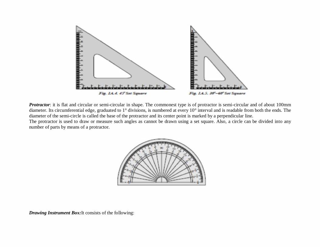
Set squares: Set squares are generally made from Plastic or celluloid material. They are triangular in shape with one corner, a right
angle triangle. They are used for drawing all straight lines except the horizontal lines which are usually drawn with the T-square.
Vertical lines can be drawn with T-square and the set square. In combination with the T-square, lines at 30° or 60° angle with vertical
or horizontal lines can be drawn with 30°-60° set square and at 45° with 45° set square. The two set squares used simultaneously along
with the T-square will produce lines making angles of 15°, 75°, 105° etc. Parallel straight lines in any position, not very far apart, as
well as lines perpendicular to any line from any given point within or outside it, can be drawn with the two squares.
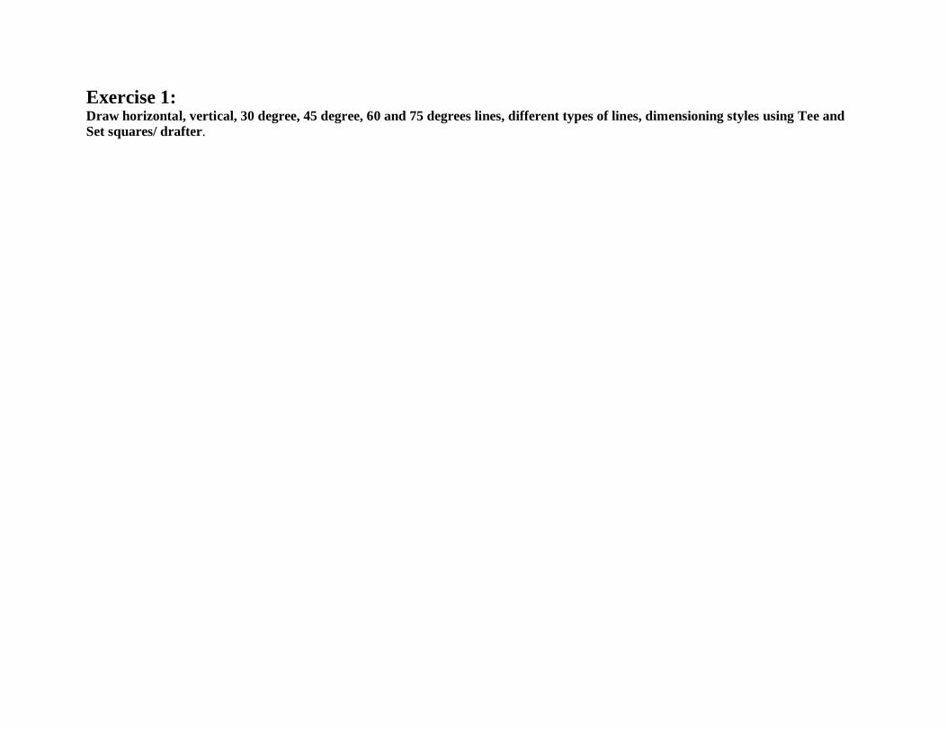
Protractor: it is flat and circular or semi-circular in shape. The commonest type is of protractor is semi-circular and of about 100mm
diameter. Its circumferential edge, graduated to 1° divisions, is numbered at every 10° interval and is readable from both the ends. The
diameter of the semi-circle is called the base of the protractor and its center point is marked by a perpendicular line.
The protractor is used to draw or measure such angles as cannot be drawn using a set square. Also, a circle can be divided into any
number of parts by means of a protractor.
Drawing Instrument Box:It consists of the following:

a) Large size compasses,
b) Large size divider,
c) Small size bow pen, bow divider, and
d) Lengthening bar
Drawing sheet:
They are available in many varieties and good quality paper with smooth surface should be selected for Drawings which are to be
preserved for longer time. Recommended sizes of Drawing Sheets are given below:
Standard sizes of drawing sheet
Designation Size (mm) Designation Size (mm)
A0 1189 × 841 A3 420 × 297
A1 841 × 594 A4 297 × 210
A2 594 × 420 A5 210 × 148
Drawing Pencils: The accuracy and appearance of a Drawing depends on the quality of Pencil used to make it. The grade of a Pencil
lead is marked on the Pencil. HB denotes medium grade. Increase in hardness is shown by value put in front of H such as 2H, 3H etc.,
Softer pencils are marked as 2B, 3B, and 4B etc. A Pencil marked 3B is softer than 2B and Pencil marked 4B is softer than 3B and so
on. Beginning of a Drawing may be made with H or 2H. For lettering and dimensioning, H and HB Pencils are used. The final fair
work however, may be done with harder pencils like 3H and upwards. For freehand sketching, where considerable erasing is required
to
be done, soft-grade pencils such as HB should be used.
Drawing Pins/clips/ tape: These are used to fix the drawing sheet on the Drawing board.
Compass: It is used for drawing circles and arcs of circles. The compass has two legs hinged at one end. One of the legs has a pointed
needle fitted at the lower end whereas the other end has provision for inserting pencil lead. Circles up to 120mm diameters are drawn
by keeping the legs of compass straight. For drawing circles more than 150 mm radius, a lengthening bar is used. It is advisable to
keep the needle end about 1mm long compared to that of pencil end so that while drawing circles, when the needle end is pressed it
goes inside the drawing sheet by a small distance (approximately 1mm).

French Curves: Drawing mechanical curves other than circles or circular arcs generally requires the use of an irregular or French
curve. An irregular or French curve is a device for the mechanical drawing of curved lines and should not be applied directly to the
points or used for
purpose of producing an initial curve. These are made in various shapes, some of which have been shown in the figure below. Some
set squares also have these curves set in their middle.

Type of Lines and their application
Symbols for method of projection
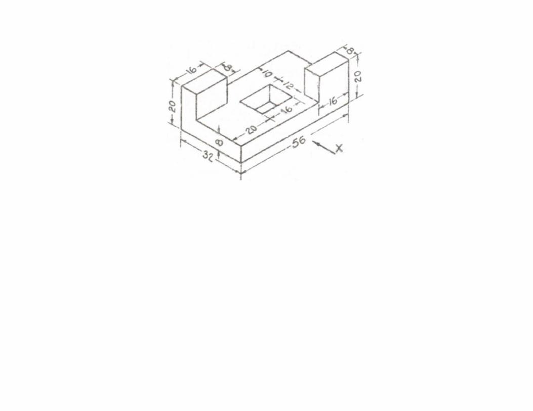
Exercise 1: Draw horizontal, vertical, 30 degree, 45 degree, 60 and 75 degrees lines, different types of lines, dimensioning styles using Tee and
Set squares/ drafter.

Exercise 2: Draw alphabets and numerical (Vertical only) (do this exercise in sketch book)

Exercise 3: a) Draw regular geometric constructions figure (do this exercise in sketch book) (fig. given by teacher)

b) Draw regular geometric constructions figure (do this exercise in sketch book) (fig. given by teacher)

Orthographic projection
OBJECTIVES:
To draw orthographic views of the given machine parts by first and third angle projection methods
Orthographic projection
Orthographic projection refers to a 2-D representation of a 3-D object in a view that shows only one side at a time. Most orthographic
drawings occur in multi-drawing sets in order to depict each side, top and bottom view. Professions in design and construction use
these types of drawings to inform the viewer of layout, size and shape.
Methods of Orthographic Projection

There are two ways of drawing in orthographic - First Angle and Third Angle. They differ only in the position of the top, front and
side views.
Exercise 4: Draw orthographic projection of the given object by first angle projection method.


Exercise 5: Draw orthographic projection of the given object by first angle projection method.


Exercise 6: Draw orthographic projection of the given object by first angle projection method.

Exercise 7 : Draw orthographic projection o9f the given object by first angle projection method.


Exercise 8 : Draw orthographic projection o9f the given object by first angle projection method.


Exercise 9 : Draw orthographic projection of the given object by first angle projection method.


Exercise 10 : Draw orthographic projection of the given object by first angle projection method.

Isometric Projection OBJECTIVE: To draw circles in oblique and isometric cubes

a) To draw circles in an isometric cube
Steps of construction:
1. Draw an isometric cube (30˚) each of whose sides measures 10 cm. Name all its verticesas A, B, C etc.
2. Bisect AF at point 1. Extend this bisector with the help of T-square, passing through Gand bisecting CD at 4.
3. Join A to C bisecting BG at 9.
4. Similarly bisect AB at point 2. Extend this bisector with the help of T-square, passingthrough G and bisecting ED at 5.
5. Join A to E bisecting FG at 7.
6. Bisect BC at point 3. Extend this bisector with the help of T-square, passing through Gbisecting EF at 6.
7. Join C to E bisecting DG at 8.
8. On face ABFG with center 10 and radius 1-10 draw an arc 1-7. Repeat this step withcenter 11.
9. With center A and radius A-7 draw an arc 7-9. Repeat this step with center G. An ellipseis obtained.
10. Complete the two ellipses on the remaining faces with the same method.
b) To draw circles in an isometric cube
Steps of construction
1. Draw an oblique cube (45˚) each of whose sides measures 10 cm. Name all its vertices as A, B, C etc.
2. Draw bisectors of all sides of the cube and mark the bisecting points as 1, 2, 3 etc.
3. Join 1-3 and 2-4 intersecting at M and extend them.

4. Withcenter M and radius M-1, draw a circle.
5. Join 5-9 intersecting the extended lines at N and R.
6. With the help of a T-square, draw a horizontal line from 8 extending towards left meeting N.
7. With the help of a set-square, draw a perpendicular from 6 on R.
8. With center N and radius N-9 and N-5, draw arcs 8-9 and 2-5 respectively.
9. Similarly with center R and radius R-5 and R-3, draw arcs 5-6 and 3-9 respectively.
10. With the help of a 45˚ set-square, draw a line through 7 intersecting the extended lines at O, P, Q and S.
11. With center O and radius O-2 draw an arc 2-7. Similarly with center S and radius S-3 draw an arc 3-7.
12. With center P and radius P-6 draw an arc 6-7. Similarly with center Q and radius Q-7 draw an arc 7-8
Exercise 11 :
To draw isometric view from the given orthographic views


Exercise 12 : To draw isometric view from the given orthographic views


Exercise 13 : To draw isometric view from the given orthographic views


Exercise 14 : To draw isometric view from the given orthographic views


Exercise 15 : To draw isometric view by using isometric scale from the given orthographic views

Free hand sketches
OBJECTIVE: To draw thread profiles, nuts, bolts, studs, set screws, washers, Locking arrangements.

Nuts:
A nut is a mechanical threaded device used on the ends of bolts, studs and machine screws. Various types of nuts are used for different
applications. The most common types are hex and square nuts.
Bolts: A mechanical threaded device with a head on one end and threads on the other end. Bolts are paired with nuts.
Studs: A rod that is threaded on both ends and joins two mating parts. A nut may be used on one side.
Cap screws: A mechanical threaded device with a head on one end and threads on the other end. They join two mating parts and have
longer threads than bolts. They can be made with slotted heads.
Machine screws: A mechanical threaded device with a head on one end and threads on the other end. The threaded end may screw into a
mating part, or may be used with a nut. A machine screw is similar to cap screw, but it is normally smaller.
Rivets
Rivets are metal pins with a head and are used to attach assembled parts permanently. Rivets are available in a variety of head styles. They
are generally used on sheet metal, such as the skin of an aircraft attached to the frame, or ship parts. The hole for the rivets are drilled or
punched, then rivet is held in place with a tool called dolly, while the other end of the rivet is hammered, pressed or forged in place.
Exercise 16 :
a) To draw a Hex head Nut

b) To draw different types of cap screws

Exercise 17 : To draw different types of machine screw


Threads: Sharp V
The 60 degree Sharp-V thread was originally called the United States Standard thread, or the Sellers thread. For purposes of certain
adjustments, the Sharp-V thread is useful with the increased friction resulting from the full thread face. It is also used on brass pipe work.

American National
The American National thread with flattened roots and crests is a stronger thread. This form replaced the Sharp-V thread for general use and
is still used for existing design.
Unified (External)
The Unified thread is the standard thread agreed upon by the United States, Canada, and Great Britain in 1948. The crest of the external
thread may be flat or rounded, and the root is rounded; otherwise, the thread form is essentially the same as the American National.
Metric
The metric thread is the new standard screw thread agreed upon for international screw thread fasteners. The crest and root are flat, but the
external thread is often rounded when formed by the rolling process. The form is similar to the American National and the Unified threads
but with less depth of thread.

Square
The Square thread is theoretically the ideal thread for power transmission, since its face is nearly at right angles to the axis, but owing to the
difficulty of cutting it with dies and because of other inherent disadvantages, such as the fact that split nuts will not readily disengage, the
square thread has been replaced to a large extent by the Acme thread. The square thread is not standardized.
Acme
The Acme thread is a modification of the square thread and has largely replaced it. It is stronger than the square thread, is easier to cut, and
has the advantage of easy disengagement from a split nut, as on the lead screw of a lathe.

Whitworth Standard
The Whitworth thread has been the British standard and is being replaced by the unified thread. Its uses correspond to those of the American
National thread.
Knuckle
The knuckle thread is usually rolled from sheet metal but is sometimes cast, and is used in modified forms in electric bulbs and sockets,
bottle tops and the like.
Buttress
The buttress thread is designed to transmit power in one direction only and is used in the breech locks of large guns, in jacks, in airplane
propeller hubs, and in other mechanisms.

Exercise 18 : To draw different types of threads.

Computer Aided Drafting ( CAD) Introduction

Computer Aided Drafting can be done by using the graphic commands available in High Level languages(HLL) like BASIC,
FORTRAN, PASCAL, C and C++ .
CAD is an important industrial art extensively used in many applications, including automotive, ship building, and aerospace
industries, industrial and architectural design, prosthetics, jewellery designing and many more. CAD is also widely used to produce
computer animation for special effects in movies, advertising and technical manuals, often called Digital content creation (DCC )
Advantages of using CAD: Increases effiency of your drawings
Time saving
Accurate, precise, & immediately alterable
Disadvantages of using CAD: Financially costs more per license
Must and should have computer basic knowledge irrespective of concept
CAD is divided in many types 2D
3D
Orthographic
Isometric
Perspective

AutoCAD Commands

Exercise 19 :

Draw basic 2D entities like: Rectangle, Rhombus, Polygon using AutoCAD
Exercise 20 :

Draw basic 2D entities like: Circles, Arcs, circular using AutoCAD
Exercise 21:

Draw basic 2D entities like: Circular and rectangular array using AutoCAD

Exercise 22: Draw blocks of 2D entities comprises of Rectangle, Rhombus, Polygon, Circles, Arcs, circular and rectangular array, blocks using
AutoCAD

Exercise 23: Draw basic branch specific components in 2D using AutoCAD

Exercise 24: Draw complex branch specific components in 2D using AutoCAD (Print out should be a part of progressive assessment)