a laboratory low temperature unit - core
TRANSCRIPT

Lehigh UniversityLehigh Preserve
Theses and Dissertations
1956
A laboratory low temperature unitJoseph Walter PasqualiLehigh University
Follow this and additional works at: https://preserve.lehigh.edu/etd
Part of the Chemical Engineering Commons
This Thesis is brought to you for free and open access by Lehigh Preserve. It has been accepted for inclusion in Theses and Dissertations by anauthorized administrator of Lehigh Preserve. For more information, please contact [email protected].
Recommended CitationPasquali, Joseph Walter, "A laboratory low temperature unit" (1956). Theses and Dissertations. 5000.https://preserve.lehigh.edu/etd/5000
.',"-' ·:,,/·~ .~. ,· . ·. ',, ..
.j
., i j
!
.J I
'l l t
·i I
A LABORATORY LOW TEMPERATURE UNIT
by
Joseph Walter Pasqual!
A THESIS
Presented to the Graduate Faculty
of Lehigh University
in Candidacy for the Degree of
Master of Science
Lehigh University 1956
I-
I
'l
:t ...
. -t .• . v
" . ·,
1 1 • ', • f ~ I •
•·'•I -J ,·,j.(
')
This thesis is accepted and approved in partial
fulfillment of the requirements for the degree of Master
of Science.
r Date ,/.~a.z<h /;:
Professor in C~
Head of the Department
I ] l .i
.... ----·_., ____ •,.
ACKNOWLEDGMENTS
The author wishes to express his thanks to ~
Dr. L.A. Wenzel of the Chemical Engineering Department
for his many suggestions and advice. In addition he
also wishes to thank the other staff members of the
Chemical Engineering Department for their adviceo
The author expresses his apprecia.tion to the
Mechanical Engineering Department for the generous loan
of the Worthington air compressor which made this project
possible. He expresses his gratitude to twos enior
students, John DeVido and Robert Ribbans, for ::i.ssistance
in preparing tho drawings and designo
11.
,. )- .
' ,)
·~·--··- ··---·- ~·-,,--,··-·--
-_l [
r
('
)
•·
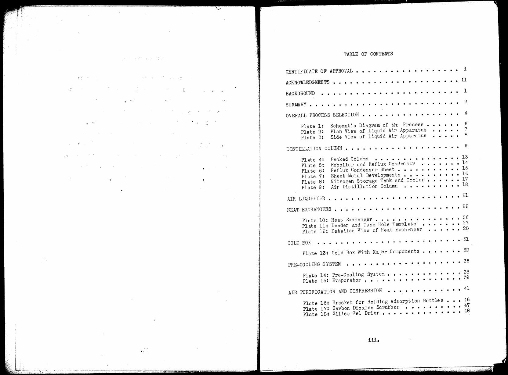
TABLE OF CONTENTS
CERTIFICATE OF APPROVAL • • • • • • • • • • • • • • • • • • i
ACKNOWLEDGMENTS •• • • • • • • • • • • • • • • • ii • • • • •
BACKGROUND • • • • • • • • • • • • • • • • • • • • • • • •
SUMMARY • • • • • • • • • • • • • • • • • • • • • • • • • •
OVERALL PROCESS SELECTION •• • • • • • • • • • • • • • • •
Plate l: Plate 2: Plate 3:
Schematic Plan View Side View
Diagram of tre Process of Liquid Air Apparatus of Liquid Air Apparatus
• • • • • • • • • • • • • • • •
DISTILLATION COLUMN. • • • • • • • • • • • • • • • • • • •
Plate 4: Packed Column • • • • • • • • • • 0 0 • 0 • Plate 5: Reboiler and Reflux Condenser • • • • • • • Plate 6: Reflux Condenser Sheet • • • • • • • • • • • Plate 7: Sheet Metal Developments • • • • • • • • • • Plate s: Nitror,en Storage Tank and Cooler • • • • • • Plate 9: Air Distillation Column • • 0 • • • • • • •
AIR LIQUEFIER • • • • • • • • • • • • • • • • • • • • • • •
1
2
4
6 7 8
9
13 14 15 16 17 18
21
HEAT EXCHANGERS • • • • • • • • • • • • • • • 22
Plate 10: Plate 11: Plate 12:
• • • • • • •
Heat Exchanger • o • • • • • •
Header and Tube Hole TemplP.te Detalled View of Heat Exchrnger
• • • • • • 0 26 • • • • • • • 27
• • • • 0 • 28
COLD BOX • • • • • • • • • • • • • • • • • • • • • • ••• 31
Plate 13: Cold Box With Major Components ••• o ••• 32
PRE-COOLING SYSTEM • • • • • • • • • • • .... • ... • 0 36
Plate 14: Pre-Cooling System. Plate 15: Evaporator •• o ••
• • • • • • • 0 • • • 0 38 • 39 0 • • • •
AIR PURIFICATION AND COMPRESSION • • • • • • • • • • • • • 41
Plate 16: Bracket for Holding Adsorption Bottles ••• 46 Plate 17: Carbon Dioxide Scrubber •••••••••• 47 Plate 18: Silica Gel Drier ••••••••••• • •• 48
iiio
. . I . .
• I •
. , .
. , I l 1 ! j ·l j
. . i
j i ·,
I . . I . ;J
. . 'l
J • n
. • . '\
• • n .
. -.-.I ...
ACCESSORIES ••••• • • • • • • • • • • • • • • • • • • • 50
Plate 19: Thermocouple Wells and Or1.fice • • • • • • • 53
OPERATION OF THE UNIT • • • • • • • • • • • • • • • • • • • 54
COST ANALYSIS
APPENDIX
• • • • • • • • • • • • • • • • • • • • • • • 56
Data • • • • • • • • • • • • • • • • • • • • • • • • • 61
Figure 1: Schematic of Column and Heat ixctanger ••• 62 Figure 2: Enthalpy Composition Graph for o2-N2 ••• o 63
SPmple Calculations • • • • 0 • • • • • • • • • • 0 , 64
Figure 3: Bent TrRntifer r1 actor ,versus 0
H ••••• Figure 4: Cooling Curves. o •••• o o ••• , •
• • • •
68 72
BIBLIOGRAPHY • • • • • • • • • • • • • • • • • • • • • • • 83
----..
iv •
,,' I
(' •l"lflll.,. .. f'.,, ............. ~ ...
0 • •
I\ 0 0 0 • 0 11 O o o a 0 . . . •o,aln•Oltft.,OOl'!>'ft II' " o o () a ,. t
J ""'oe,01"o•••n . . . )
. . OIOllltGO,_,.Gfl.
Q rt O 1J
' . . • • 0 '1 I O " IJ
. . . . . o t a 4 f'I o Ct ct r,.1>t,ooO,..o
• · .r '.
)
.. i
,j
l j '
BACKGROUND
The design presented in this thesis was suggested
by Dr. L.A. Wenzel when the author was looking for a
project for his Master of Science Degree and ex.pressed an
interest in low temperature processes. Dr. ienzel, in his
original suggestion wanted a low temperature unit that
could be used to fractionate air. This unit was to be in
the neighborhood of ten feet tall. The unit was to have
enough flexibility to allow experiments on several phases
of low temperature work to be performed.
The unit as designed provides a suitable arrange•
ment of equipment to allow experimentation to teke place on
fractionation, pressure drop in packed towers, liquefaction,
heat exchange, and air purification. In addition, the unit
can be used to provide liquid air or nearly pure liquid
nitrogen a.s a low temperature source.
I , '
[
') ( . ~ 1 (".
- I -
·l
l ·1
J
'i ·)
SUMMARY
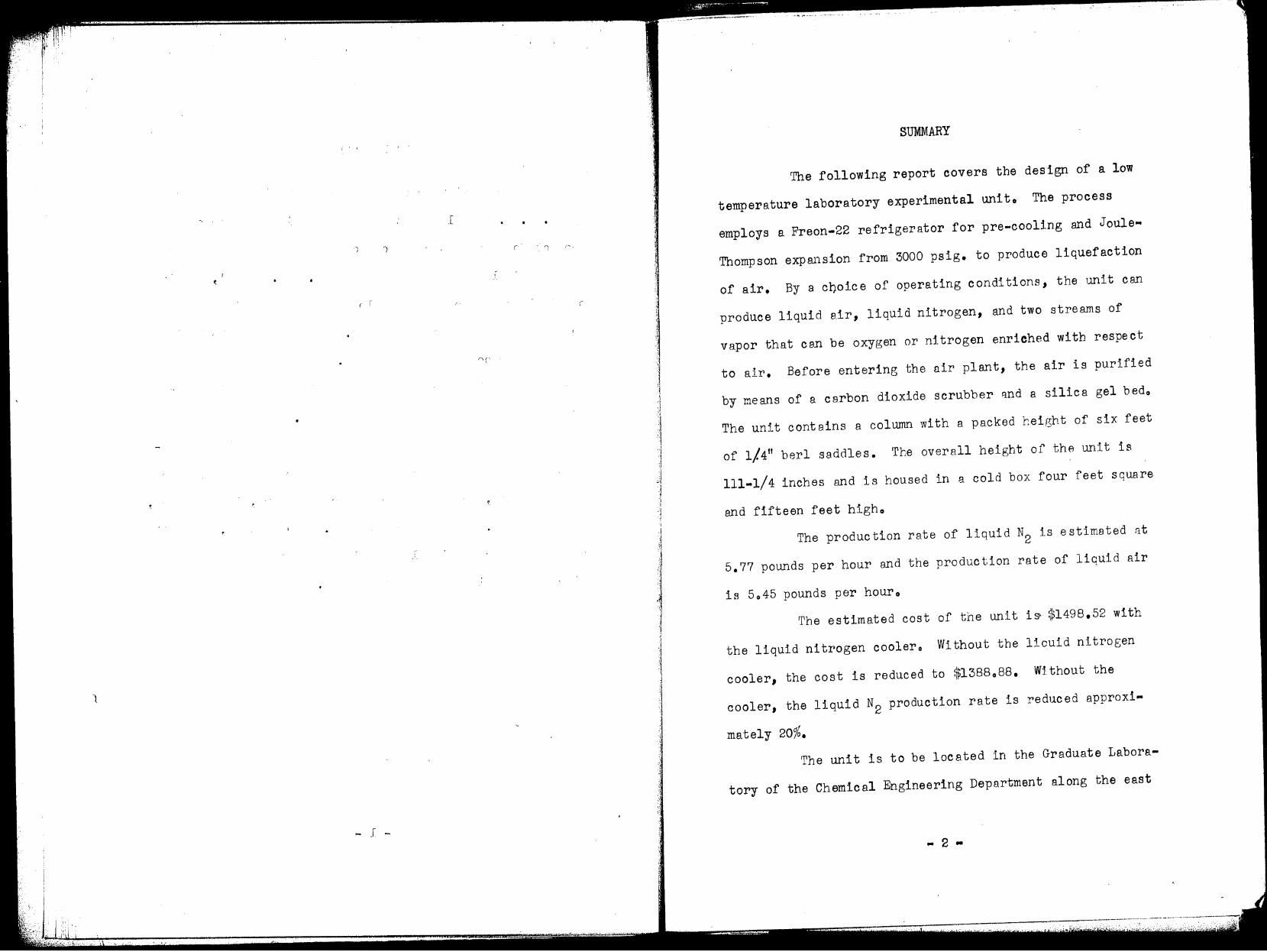
The following report eovers the design of a low
temperature laboratory experimental unito The process
employs a Freon-22 refrigerator for pre-cooling and Joule•
Thompson expansion from 3000 psig. to produce liquefaction
of air. By a c0oice of operating conditions, the unit can
produce liquid air, liquid nitrogen, and two streams of
vapor that cen be oxygen or nitrogen enriched with respect
to air. Before entering the air plant, the air is purified
by means of a ca.rbon dioxide scrubber i:i.nd a silica gel bedo
The unit contains a colwnn with a packed height of six feet
of 1/.411 berl saddles. The overall height of the unit is
111-1/4 inches and is housed in a cold box four feet square
and fifteen feet higho
The production rate of liquid N2 is estimated nt
5.77 pounds per hour and the production rate of liquid air
is 6045 pounds per houro
The estimated cost of the unit i~ $1498.52 with
the liquid nitrogen coolero Without the licuid nitrogen
cooler, the cost is reduced to $1388088. Without the
cooler, the liquid N2
production rate is reduced approxi•
mately 20%.
The unit is to be located in the Graduate Labora-
tory of the Chemical Engineering Department along the east

•.l 'I - :' r
·, . .. l
- _I~ ('
'\
.... ; ')
r
')
I.
- .
('
• r" , I
,- . C
I,
'\
\ r-s
(
. (
l '
,1 ., r '
·,1'·t· .. ./ ... ,·
wall. The cold box will be next to the door and the
apparatus will extend along the wall tow~rd the Heat Ex~
change Institute equipment for a length of thirteen feet.
... 3 ..

) ·;· r. - r . . r .
,, r
' I
;
>.
' !
·, ,'J "J l ,I 1 ;i l
.1 .,
OVERALL PROCESS SELECTION
One of the first things to consider in a low
temperature process is the source of'refrigeration. The
refrigeration can be obtained by expanding at constant
enthalpy through a valve or at constant entropy through
an expansion engine. The former process requires a large
amount of compression while the latter process requires
an expensive expandero The loan of a high pressure compres
sor from the Mechanical Engineering Department obviated
the choice of Joule-Thompson expan.sion through a VBlve for
the refrigerationo
Since pre-cooling the air before it enters the
main exhangers allows more liquid product in be made in
any ltquefaction process or allows the use of a gre9.ter
heat leak, it was desired to include a pre-cooler in the
process. This was done since the Chemical Engineering
Department owned a refrigerator compressoro
Because of height limitations, it was decided to
operate a single column rather tr.a.,.'1 r.. double column for
distillation. It can be shown that a single column can not
produce both oxygen and nitrogen in a pure state {12)o
Nitrogen was the product selected to be pure. This selection
was made because it is easier to distill nitrogen from a
,[
'\
•
')
'\
- . -
·I
·.~
' .I
'l i 'l
1 ·J 1
I
i 'I l l ·,
I :1 ., I
l i' i
! I
l 1 j 1 I ' 1 l ]
J
l
mixture of oxygen, argon, and nitrogen than it is to distill
oxygen from the same mixture. This is so because of the
close approach of the vapor pressures of argon and oxygen
(1). In addition, liquid nitrogen is colder then liquid
oxygeno
Other, more detailed, selections of process
conditions are covered in the sections on the design of the
particulnr unit in question.
/
- 5 -
I I'.
r ,- .. ·
')
l t
~- ' ....
', r t f.
1 I
..... ' ..
. :I .,
·:1
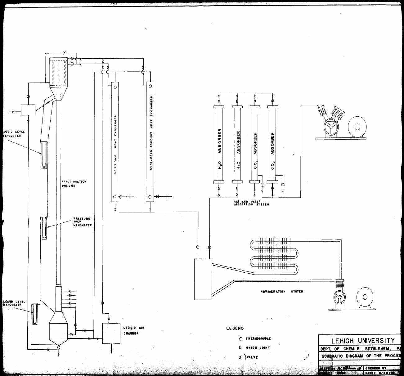
Plate 1: Schematic Diagram of the Process
IOUID LEVEL
AHOMETER
LIQUID LEVEL MANOMETER
,·~:,_•.
'1 - -r, - ,,-I I 11 I 11 I 11
11 11 11 11 11
11
II 11 I
Ii _ IL_ ~I-
FRACTIONATION
COLUMN
PREUURE DIIOP MANOMETEII
0
a: Ill C, z ,c :z: c., X
a: l&I LIi Cl I-z ,c
"' Ill :i: :z: u a: )( I- w LIi c., CD ::, I- Q a: "' 0 0 LIi a: :i: a. Cl)
Q CD
"' <{
UI l&I
:ll ':I: 0
I
a: 0 I- l&I N I- > J: 0 0
ID
0
LIQUID AIR
OHAMIIII
i·:.
a: a: a: Li.I w w m a: CD m 0
a: a: 0 0 U) Cl) Cl)
CD CD CD <{ <{ <{ I
N 0 0 "'
OI 0 J: 0 (.)
GAS AND WATER ABSORPTION SYSTEM
Rt:l'IIIHIIATION IYIT!M
LEGEND
0 T H IIIIIOOOUPLI LEHIGH UNIVERSITY D UNION JOINT DEPT .. OF CHEM. E. BETHLEHEM p
}( JYALYI / DIAGRAM OF THE PROCE
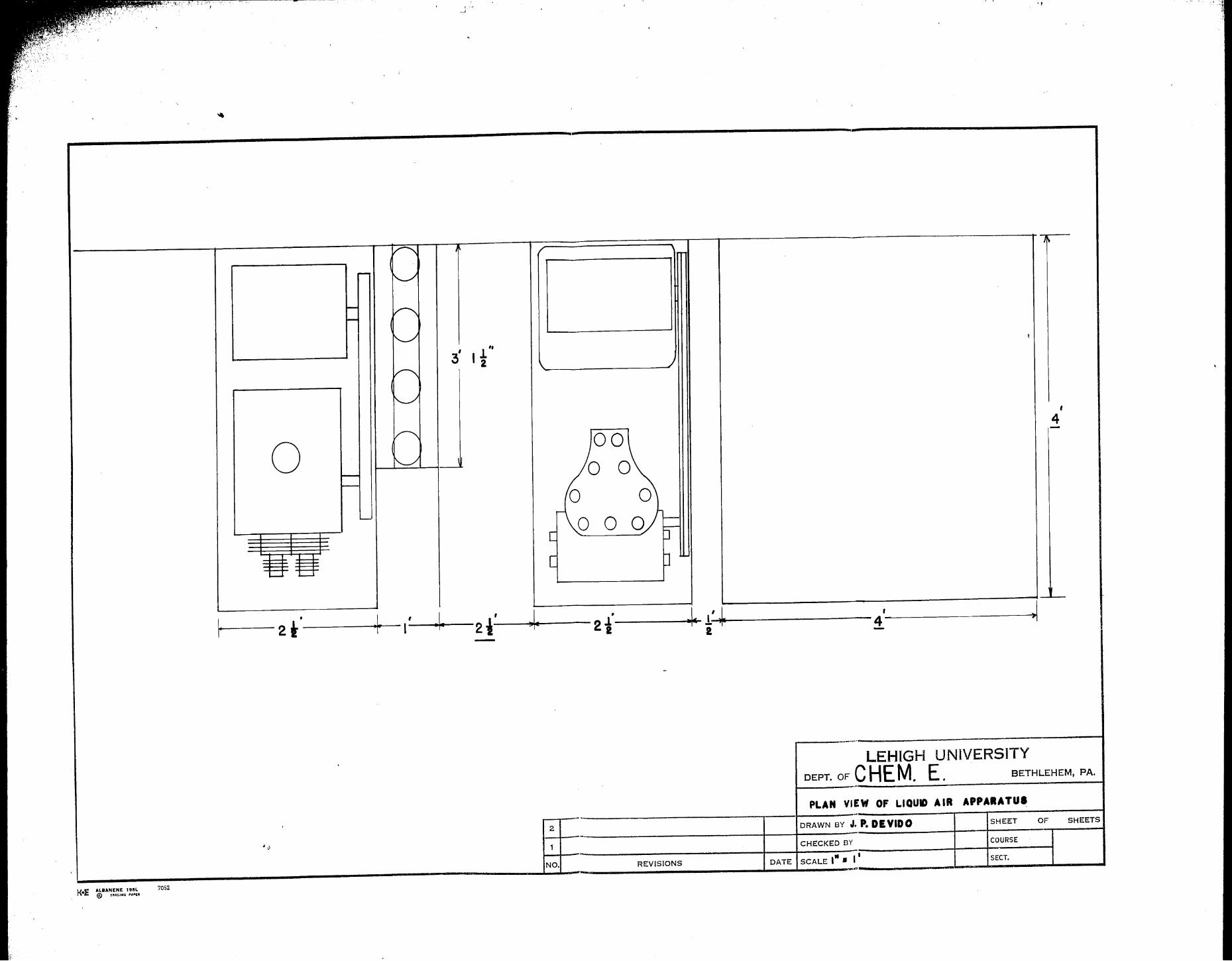
Plate 2: Plan View of Liquid Air Apparatus
/
... 7 ..
K•E ALBANENE 19SL @ TflAt.lNQ PA.,lR
7052
0
I
·-·'
! ,, I 2
00 0
0 0
i.---- 2 t ·---------1-' ___..,.~--2 -1-' ---)!--~ -- 2 ·f
2
j ..,;l 1
NO. REVISIONS
'I
' 4
-~ 1-'---~~~~~~~~~~4'~~~~~~~~~~~ 2 -
LEHIGH UNIVERSITY DEPT. OF CHEM. E. BETHLEHEM, PA.
PLAN VIEW OF LIQUIO A IR APPARATUS
DRAWN BY J.P. DEYIDO SHE!::T OF SHEETS
CHECKED BY COURSE
DATE . ,.
SCALE I • SECT.
' I
I ~ ,~:· .. 1
i:
I.! II\ I r ,,
·, Ii
\ J
j
J I I
I
I \
I
,.- ,/,
··~·'1_,~";ii•'
-,y. ii_
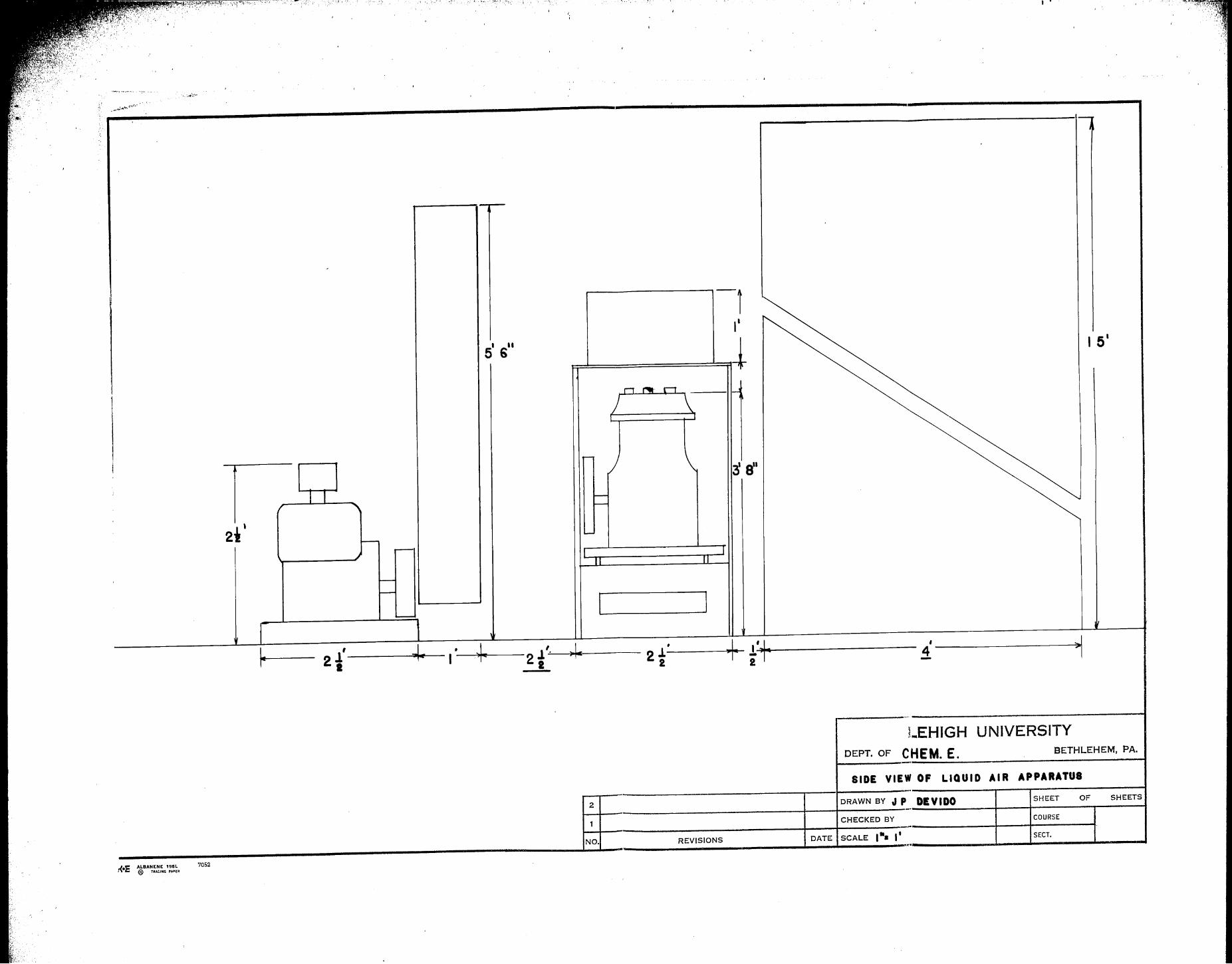
Plate 3: Side View of Liquid Air Apparatus
,; ,',
,,r
'/ i
- 8 ...
i '
. ,__ . .;..,...._ ., .... ~
I
--
' -, I'
s' 611
-!-I 5 1
r, "' r, -) \
I I
i ,..._
3 e" l I I -
r "" -
2i' - ..... ....--
,J I
II II
' -,--
- I I ' I I
V
~ i' ~ • ~ J. '· )o~
, + *'+ ' ~' 2. I 22 2l i ... ,
2
"
1.EHIGH UNIVERSITY
DEPT. OF CHEM. E. BETHLEHEM, PA.
·-SIDE VIEW OF LIQUID AIR APPARATUS
2 DRAWN BY J p DEVIDO SHEET OF SHEETS
-· 1 CHECKED BY COURSE
NO. REVISIONS DATE SCALE 1•a I' SECT. ,.
J{ E ALDANENE 195L O ® TIIAC.ING f'AlltR
7052
• 1
-
---
II
~
',~ .. ,. .... , ....... ,h.-.~~-.... .,.._~,.-~,-·-.. -· ·----~----·-···----···---·~, .--,·
1- ----- -- . . . . . . .· . . . .
• r. "'
I/
+ •
~
,-
' --
-~
\/
I
'1 · .. s -I
i---··-.. ·-··. ·~---· --·-·--··· --.-·--··---·----·---·--·-·-·----~ .. ·-···-.. -·-~ 1 YTl2S:[3VHllU Hvll'-[3_
,.._,~~,.,~-""'"" _______ ,.,. "" . -·----·~
T33HZ
--·------t---'T""'------3251UO:>
.T::>32.
'. ~- \ ••. f, ·, .••
.
I
'ts
l ~
I
l
.-. ·)
> 'r :.1 ·-·
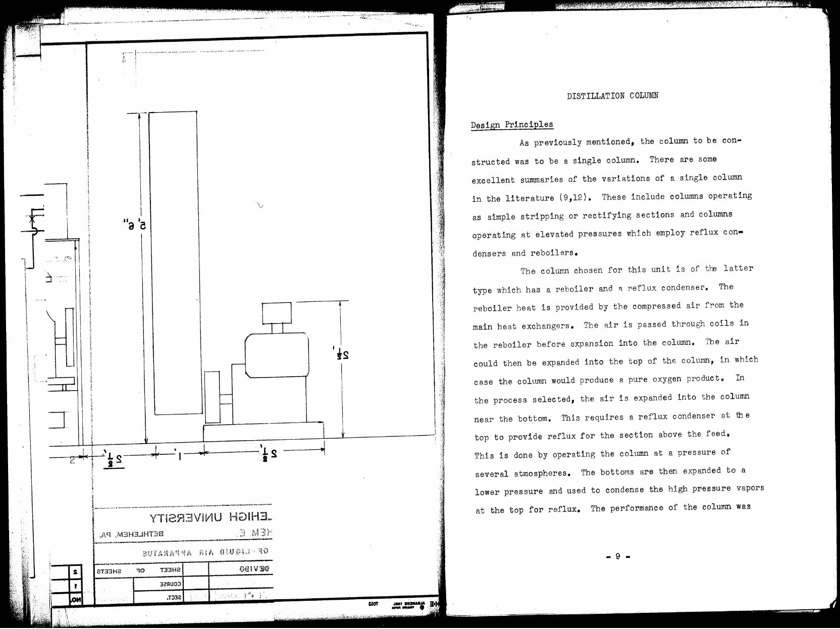
DISTILLATION COLUMN
Design Principles
As previously mentioned, the column to be con
structed was to be a single column. There are some
excellent summaries of the variations of a single column
in the literature (9,12). These include columns operating
as simple stripping or rectifying sections and columns
operating at elevated pressures which employ reflux con ..
densers and reboilers.
The column chosen for this unit is of tre latter
type which has a reboiler and 8. reflux condenser. The
reboiler heat is p11 ovided by the compressed air from the
main heat exchangers. The air is passed through coils in
the reboiler before expansion into the column. The air
could then be expanded into the top of the column, in which
case the column would produce a pure oxygen producto In
the process selected, the air is expanded into the column
near the bottom. This requires a reflux condenser at the
top to provide reflux for the section above the feedo
This is done by operating the column at a pressure of
several atmospheres. The bottoms are then expanded to a
lower pressure and used to condense the hi.gh pressure vapors
at the top for reflux. The performance of the column was
- 9 -
i t I I
I § ij I
I
I i
j -,"'l.;.\ i r I
t
~ ! I i I
I I ~ I ! i I ' i
•;:\ ~:.,
• - I
_[
·'J s -
r '
• ' n. .li • ;; ···, • - ~ ···-'' • ·,.·· ..,.,•
;
r
'' _l.' ; :,
' ,,
:~1
.
:;;'.l ,,' ,, j.,
i~
calculated by means of material balances and an enthalpy
composition chart for o2~N2, The calculations were per
formed assuming air was a binary mixture of oxygen and
nitrogen, This was not considered to have any serious
effect on the calculations because of the small !31'.Ilount of
argon present and its similarity to oxygen. For a 98%
nitrogen product, which includes both a gaseous and a
liquid product, the maximum oxygen product was 37o5%
oxygen for an infinite column. When the column was re
duced to 13 theoretical plates, the oxygen concentration
fell to 35% oxygeno
Allowing a 15 psig. drop in the vapor lines out
of the cold box, the pressure in the shell side of the
overhead condenser was establishedo The temperature 0
difference was selected at 10 F. This set the pressure in
the column at 805 atm, or 125 psia in order to allow the
nitrogen to be condensed as reflux. Equilibrium data was
available at sever Bl pressures ( 1, 9 ,12) so extrapolation
provided equilibrium data for the particular operating
pressure desired.
Heat transfer coefficients were available for
evaporator condenser units (7), boiling coefficients for
oxygen and nitrogen, and coefficients for condensing oxygen
~ 10 ..
.,,,·.,. . !
(
[ r '.-1 t 1. !, •.• ,..
·-i
r
j
-
~
-.,,, ! )
~-
I f
I .
r :-
.. ,...
r· .
)
. ' - (
('
• ('
L
J'
\.) ,, , ..
·., . /f
'~
and nitrogen vapors { 6). This data along with a knowledge
of the heat duties required enabled the reboiler and the
reflux condenser to be sized. The heat transfer coefficient
inside the tubes was obtained from the~ factor discussed
in the section titled Heat Exchangers.
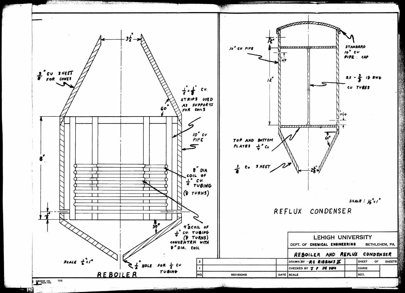
The tubes in the reflux condenser are flared at
each end. This increases the capacity of a unit over one
of similar dimensions with square edged tubes (6). The
effect without flaring seems to be that the liquid which
condensed in the tubes forms a bead at the bottom of a
square edged tube sealing it offo The vapor stream is
taken off above the tubes to prevent the accumulation of
non-condensibles. These have an appreciable effect on the
heat transfer coefficient if they are allowed to accumulate
( 7).
Data in the literature on H.E.T.P. indicate that
1/4" ceramic berl saddles are the most efficient type of
packing for this operation except Stedman packing (l,9)o
However, Stedman packing was considered too expensive for
useo The H.E.T.P. for the berl saddles varies from 2.5 to
6 inches depending on approach to flooding and column
diameter. The H.E.T.P. decreases as flooding is approached
and increases as the column diameter increases with constant
mass velocity. Ceramic rings have about the same value of
.. 11 ..
')
:,:;_,, i.
~ I
-
-._
: .._
I II
~ . ~
[ L
. r
I
\
(' ' . ' • I
' )
. . .. .
l
(· -
< r ') . . . .
.., ll -
r
. ' ') r
·'t, /·'
,·.
j ··,
~r ,., •' , -, !
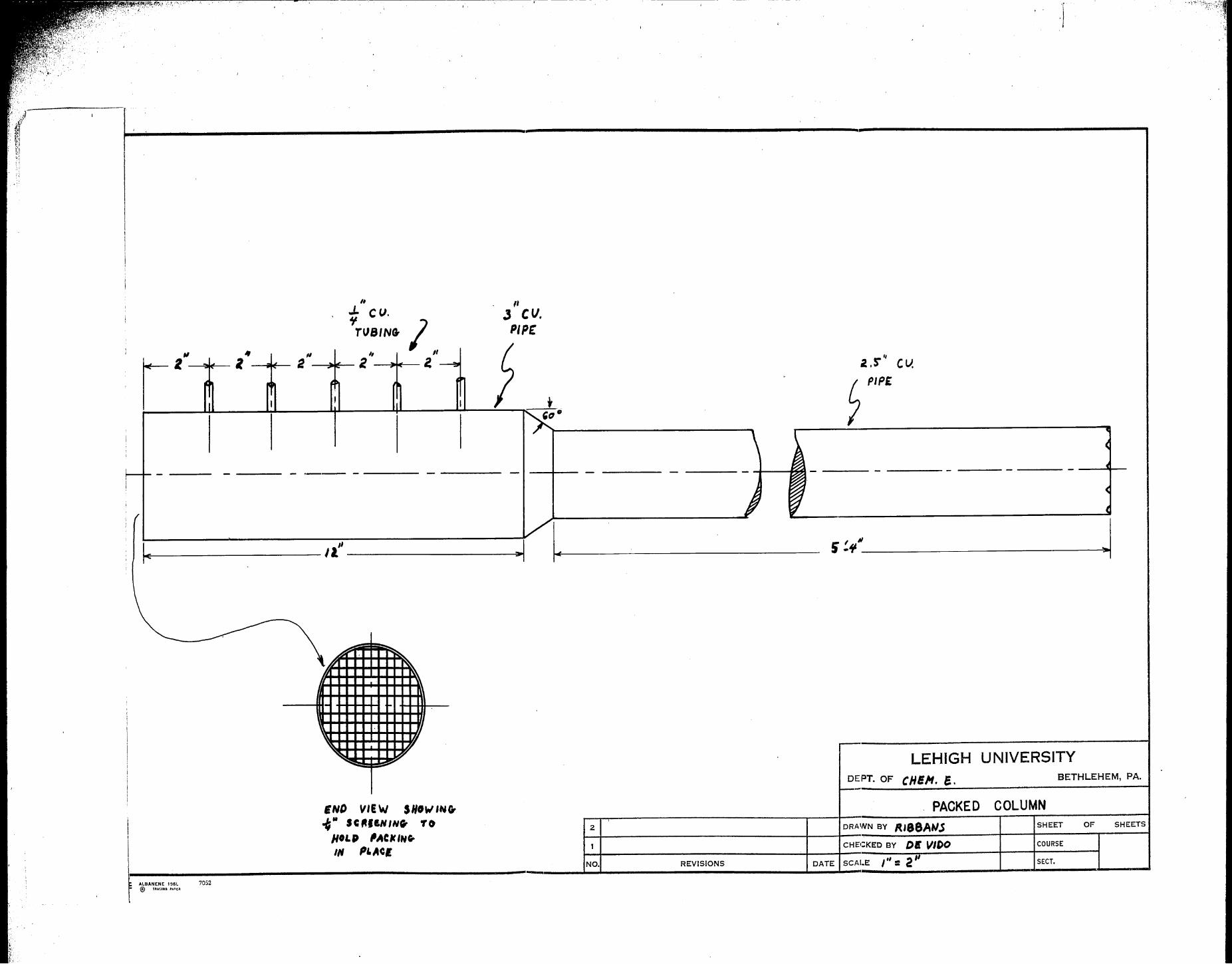
H.E.T.P. but have a lower flooding velocity. The flooding
velocity for 1/4" berl saddles is reported as ranging from
1550 to 1800 #/hr.rt2 liquid rate (1,9). The column size
is determined by choosing a size of pipe that keeps the
liquid rate below flooding yet high enough to give a low
value for the H.E.T.P. At the point where the feed is
introduced, "'.ihe column is wide·ned to allow for the extra
liquid load. The liquid and vapor rates in the colwnn Rre
calculated with the aid of the enthalpy composition charto
.. 12 ..
:'-··'1··'·,_.
I
'
i ,,
I .L i
cv. .y
lH TUBING I I ,, " "
,,
I' - l - . 2 - . 2 - 2~ -, . - ,
C
I I ' I I
'
f--- - - ·--- - -I
;
/ I
,, - 11
I -
;o: ~
' ~ "I:
I,, ~
- .
-
~ 7.
• , .... ~
ENO VIEW SHOWINCr
I {" SCl'IININ. TO I HOLP ,ACltlNG,, I IN PI.ACI \
~ ALBANENE 195L 7052 r @ TRA<IHO PA'<R
,, J CV. PIP£
' C
I ' '"" I
~ - - - - ~
) I:..
V --
2
1
NO. REVISIONS
i .s-'' CV.
~ PIPE
- - -
I II s .t;
LEHIGH DEPT. OF CHEH. S.
:.---
PACKED DRAWN BY /U88AW.S CHE1:KED BY D~ Vll>O
DATE SCAI.E ,., = 2''
~
C
-- -4
4
-
UNIVERSITY BETHLEHEM, PA.
COLUMN SHEET OF SHEETS
COURSE
SECT.
i<i
'
,, , '~t --+ V
uq ·-
.j r~
(
1
l\ 1\~~~~~~~~~~----i
~ ~ ,., ~
" ~
'
- ....
~, l
,,,...,......,...__ ... ........ ,.~ ...... ,. .... "' ... ~...-,-··-
~t~IE~ t I ~i~1IU H ,lv13H3JHT38
·-4 .. ..-.. ----·-., ... . -------. ... -----Wf1~1U901
'r,m¥111# __ .., ___ H .. d•--
.:ao\' .IHt Jll:IIIAI.IA ---.
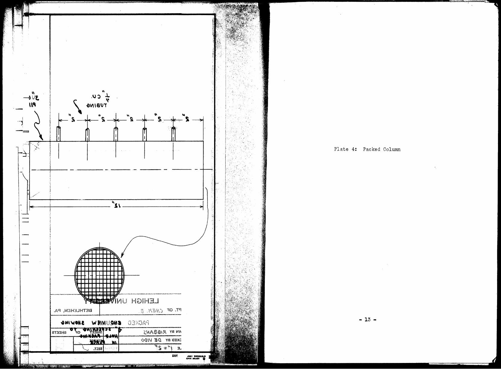
Plate 4: Packed Column
,::
,, :',./ .,,
- 13 ...

,, ., '~t ' \A~
·-""
...
\
Plate
1f J ..
.. ~ .. ···--'"..-.-.-·-, - .. -.,., .. , .. ., •... , ~r-·
..
5: Reboiler and Reflux Condenser
P!t 14 ...
• .J. cu ltlttT • ~OR
a"
7052
" .. f "t '"·
11'/ttPS tJlfl> AJ StlPPoRTS FO~ c., .. ,
,, t DIA
COi&. OF J.. t t,/.
" rve11#& · (t TCl~HS)
2
1
NO.
lo II CII /IIPI
REVISIONS
RE f LUX
JTA#OAIU> /0" Cu ,1,1.·-: CAP
T
S CAL• : )$ 11-: 1 "
CONDENSER
LEHIGH UNIVERSITY DEPT. OF CHEMICAL ENIINIIRIN8 BETHLEHEM, PA.
DRAWN::av --RC tt,1,A#J Ill . SHEET oF
CHECKED BY f' , Pf trll• COURSE
DATE SCALE SECT.
1.:· ,, ,•
HQIH3
. ,,\ \
-i' .:i!· •. I ·J.
•;
:: ~·:
Plate 6: Reflux Condenser Sheet
... 15 ...
.';11
:\
• i ·I
I II - H OL. E.
,, 2.'"i DIA.
" /0 DIA
s''o1A.
,, r DIA.--LEHIGH UNIVERSITY
.. J,/' -,, TH f!C I( C Cl 111 a r r DEPT. OF CHEMICAL ENIINEERINI BETHLEHEM, PA.
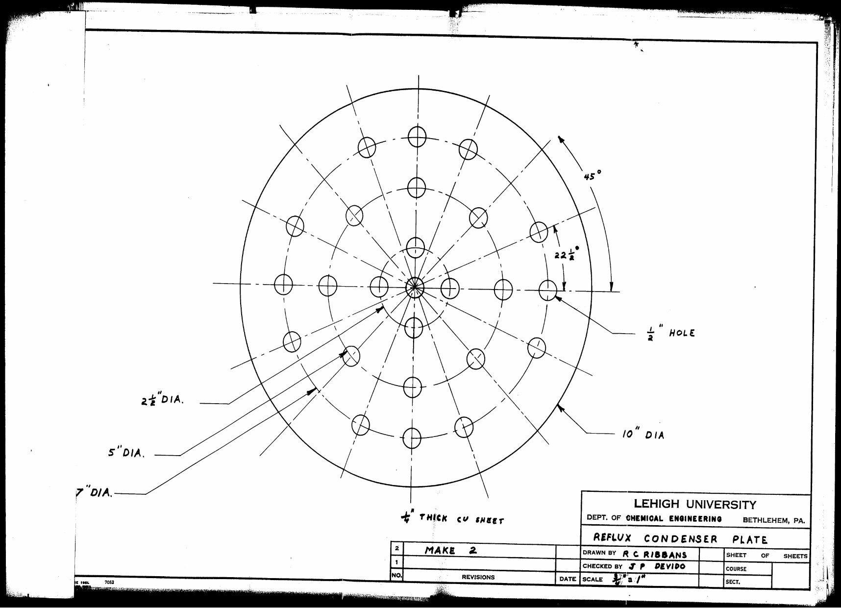
AIF1"VX CON DEN.SER Pl AT£ 2 MAI<! a. DRAWN BY R c. R ll8ANS SHEET OF 1 OIVIOO COURSE
NO. REVISIONS
l' ;c: f: 1{:i
i ~! II f r ! :.-
'·, ,' '
.--+ I
l
' ~ i
! i '
li
~-~-.. -··--b,,,,_....~ .... --1
_,,_ .... ,,._ .. , .•. ,.
f" T'"'··.
1 ' i r··-··-;----...... _ .. I ·, I r~,a, ....... i"'"""""' ___ ,._
;NO.
' 1 '! 'JI
I 'c
'\ I :l
~ j 1
·-r-'· .. \
\k,,;-. ...
-z
,, . A\ Q "2.
,;t~'' j
:-,.,_?,!t.·.·-.. , },. :.'";::
,·,
I I ).'
,!
, ~ • r
I'
Plate 7: Sheet Metal Developments
... 16 ...

-
FLANII ,011 TOP
0, 1111 OILI II
Io"
FLANIE FOIi
REFLUX CONDENIEII
. ·--~···" ~ .,,:,,_ •. ; .... ~ .• -,_;/.,;~;,.if'':! .
FLANII , OR JOINING THE
TWO IICTIONI OF THE COLUMN
FLANGE FOIi BOTTOM
Of RIIOILER
LEHIGH UNIVERSITY
DEPT. 01=" CHEMICAL ENIINEEIIINI BETHLEHEM, PA •
.--r-----------.----1---=S~HEE·T METAL DEVELOPEME.NTS
2 DRAWN BY SHEET OF SHEETS.
1 CHECKED EIY COURSE
-:1===~~7:os;-2 ------------------------....J~N,;;0·:1... ____ _::RE:;:V,:1s:•o;:N:s _____ ~o:A~T:_E .Ls:c~A~L:.E ..!'~· .:.· !~~-----..L-...1:!sE::cr~. __ .J. __ .....J: J
i· ;
; F
1 AO'=I! i&MAJ;
)µ11MOO t.: XUJ'=l'JA ,,
( ,1
/ j
CIOT RO .. JIIIAJ
RIJIOIJR t
32f!UOJ
.T:>32
·'••,'1"-;!'Jl.'"~
YI
£i10\' .
I ,l
JNI :IIIIIIHJA .. ~ .. ·--. 'I !
t,:. \,.'.:
i~ I'. I
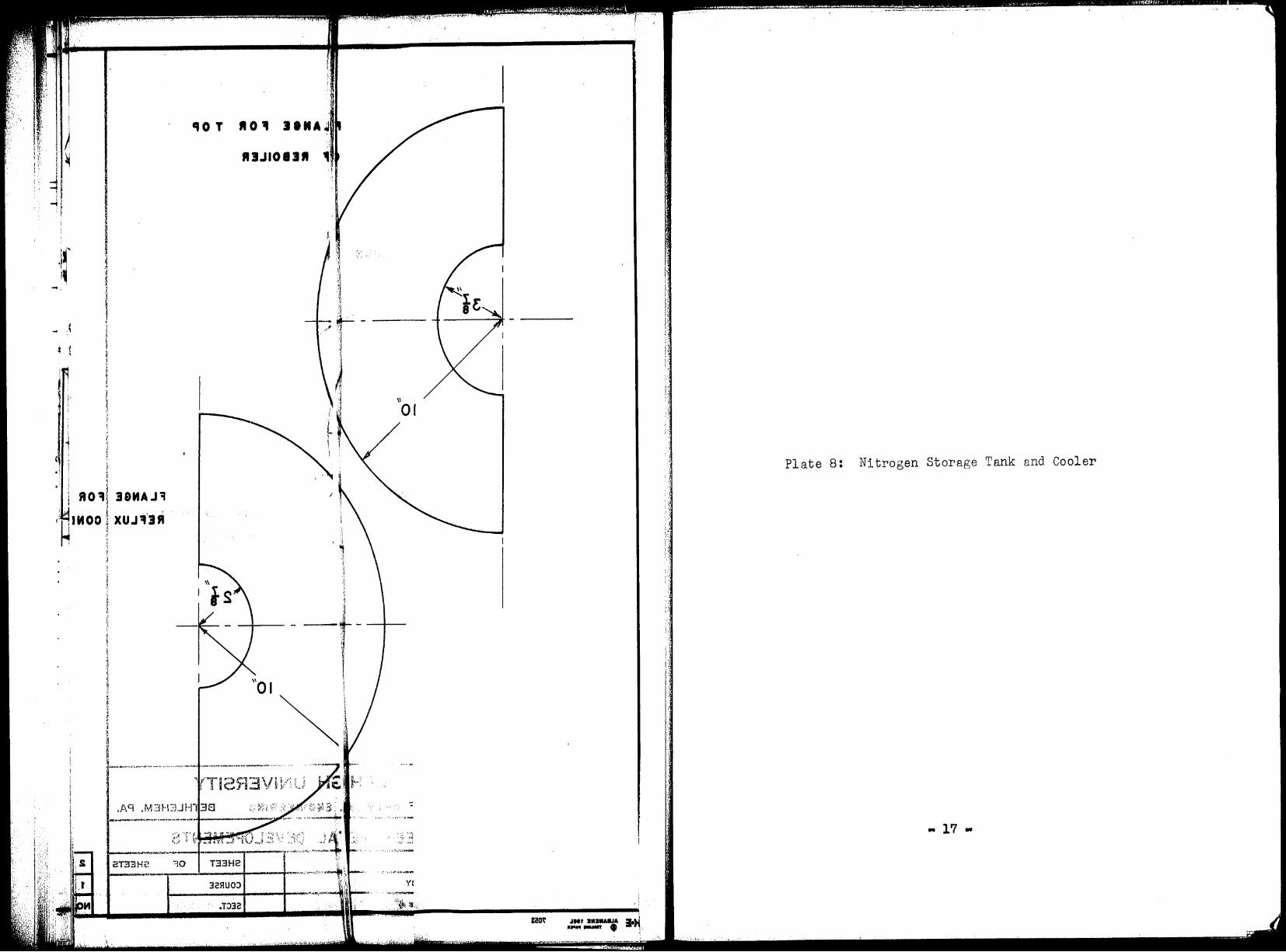
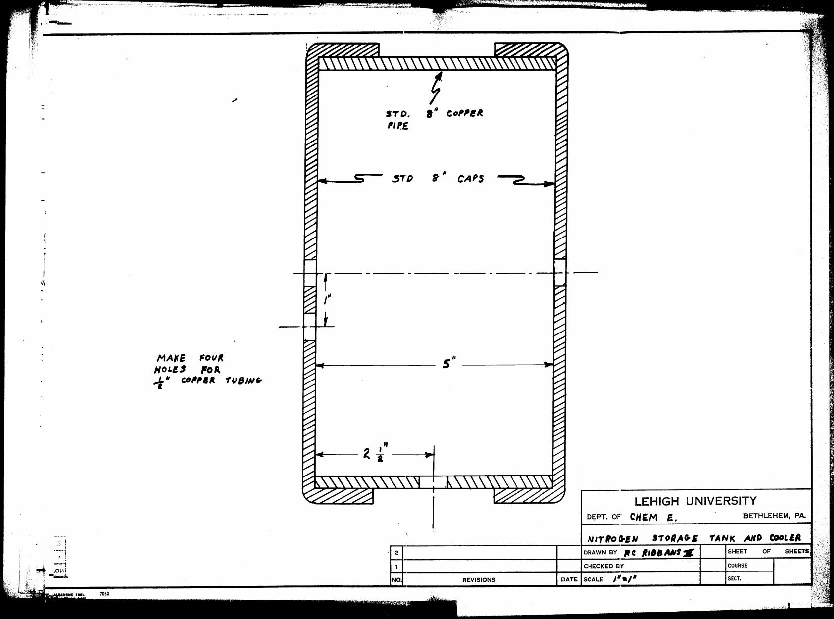
Plate 8: Nitrogen Storage Tank and Cooler
.. 17 •
r; i - I
·-··i t I
;/.·~.· ·~,, l, .... '
....... ,..,."n ... ,- -,,, ... --,--,-·.·· ... ,.
MA~E FOV" HoLi, FoA ~" co,,11. 1'1JB111•
I
STD.
'' '-E.
~TD B'" CAPS
5"
' 2
1
NO. REVISIONS
LEHIGH UNIVERSITY D.EPT. OF CH EM E. ' BETHLEHEM, PA.
DRAWN BY It C , ••• AMI.. SHEET OF
CHECKED B'f COURSE
DATE SCALE 111•1' SECT.
,·.,,.•··;··.1· ... "•'' .. , '
ii' ;I
1' ii
....
/ ''
E. I
.. , ~::·~·;,~ •• " - .• ,, ....... ,,# -~·--·,.1-· .. ! ~~ii,;a1~~i,;;.i..~i.!lli•J , r ,
"" 1
,.,, ... ~"111 ,.,,!.('''' ,::,/ 1 k.i t::. i 'J; .. .c .. ··t ;_ J';J:, -~ ; • ,,
. , ""'·' .... ~-~· .. ·----·,-,,,---·,-,,-,,·- -'-'I
'f'Af·d( MD (COLE.A ~ {',.Hr,;:Er Or ' li ,···)'!.l"'' "'· ., '~-'.. ~~l.
SECT,8MOl81V3
c::11
I J,
1~ t'' ( I' i'l
'?
!, ,. i·
f
' - .~ .. --·· '·~· ···-·· --· --. .......
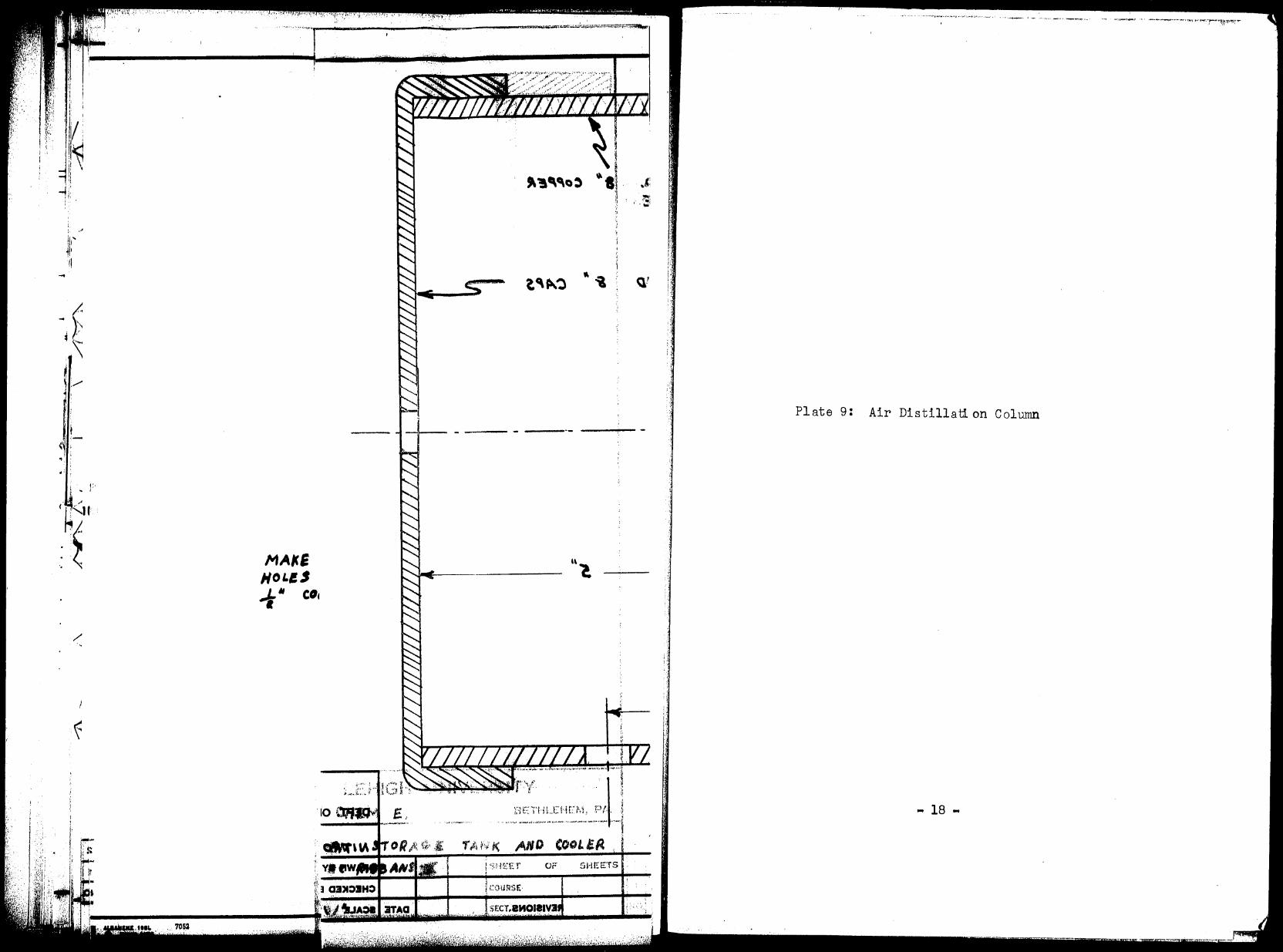
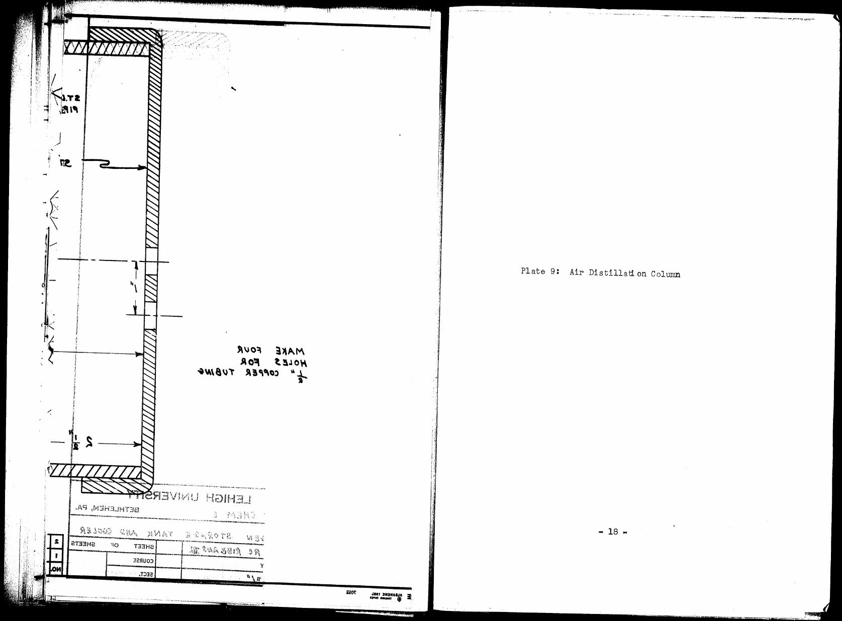
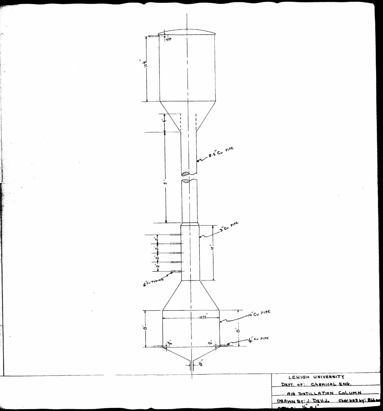
Plate 9: Air Distillatl on Column
... 18 -
:-
< ., f
• i
l ,, \
)\\JO~ 3)1~"" Ao~ t. a.1 o~
S\!,C\Ol ~ ~ I
._ ... ________ .,.« .. ,..._,_,..,.,,., ___ ,...,.,,n•~ •--.H~•·. _ ....... ,.,_,,..,..,.-._..,n,o~..-v--.,~._,...,....,.,,...
2T:33H2 ..... '" - ...... ....._....______._, _ _,_ ___ ..,._r·-,"" ..... .......,..,.._...., ... ___ • -----
, . ·1-,,-rp~ 1~} f•'h. C\. -~ r.., il ~\ ::'l- 1~\ i ,.n;ij,1_ '.t- -V~-~!,f; ~., ·:..:~ ~ t\ ,,:; l!-~l -·-·,--~--·- ~ - ••• y
i-_____ _.,. ___ 1,..,.._-QO,,,"'I .... ~
T.33H2
J2flU0:)
EaO\' JIii JIIIMAIJA :r, ·-- ($ ..,
1:
Plate 9: Air Distillatl on Column
- 18 ..
. ~". j
. f
.1 t
r- _.-10°°Cw '1-----1------10.1-~
Q'.) C I co
J._ c .. PJPE 4f'"
LEH \GH u N\VE.Q.~ITY
0 ~ ·. C:..\.\ Ill"\\"'
1·1~""!-H''.·«•• -~,~ ........ ;.-. r-c,.;,-.-, ... : .. ·
....
-,
~
~ 1 ..
~
Y-
< ,, ..
(
,· ·'·
··'
., .. · ~'". :., -·~ . _-,
f'· r. ,•:,"'..,
Construction
When the cones are rolled to the proper size, it
is recommended that the seams be welded shut with silver
solder. The cones for the reboiler and the middle section
of the column can be joined together with silver solder,
but it is recommended that the junctions of the reflux
condenser and the reboiler to the column be mHde with soft
solder. This will allow easy removal of these sections in
the event the packing must be removed.
The screen at the bottom of the column should be
made from 1/8" brass rod silver soldered in the form of a
grill. As the packing is put into the column, the column
should be tilted to prevent the packing from being crushed.
Occasionally, as the column is being filled, it should be
tilted upright to e.llow the packing to settle properly,,
The nitrogen storage tank and cooler is mounted by
the pipe running through it from the reboiler ID the overhee.d
condenser,, It should be fastened on at a level below the
liquid level of the nitrogen trough at the top of the column.
C e..re should be taken in the location of valves so that all
the valves may extend out the front of the cold boxo
When the column is finally mounted in the cold box,
care must be taken to see that it hangs vertically. If the
column is not vertical, it may have a serious effect on the
H.E.T.P. of the packing (9).
• 19 •
J .,
... < 1'
..
....
:~
< I
J
.I
·,
... ~I -
:,;'.1•,:
Lr' : ·' ,... .' .. . (' ................. , ...
.•.C
. . . .
,ri
:1 ., •I
l 4 11
:I \1
l .,
After the column is constructed, it should be
hydrostatically tested to a pressure of 300 psig. If this
is done with the column in place, care must be taken to
see that the column is thoroughly dried before operation
is attemptedo
•,20 •
" 1'
11
f' ~1 · '' If ·"1:,,J/·· l t '' l .r. :.j:•<lll· i I ,
~-
''
:: j
l
1 J ,, :i
:~ \,
r
AIR LIQUEFIER
Design Principles
When the thoroughly cooled Rir from the heat
exchangers is expanded, a portion of it will form a liquid,
the rest remaining a vapor. The liquefier is merely a tank
into which the air is allowed to expand. rrhe 1 i.quid
collects in the bottom of the tank and the vapor is used
to cool off the incoming air. The amount of liquid air
produced can be calculated by an enthalpy balance around
the apparatus. The liquid air can be allowed to ace umulate
in the tank or can be drawn off to the outside Rnd collected
in a Dew~r flasko
A stainless steel tank WAS found in the Chemical
Engineering Laboratory which fitted all the requlrements of
the liquefiero This tank is eight inches in diameter and
ten inches tall. It is equipped with two fomale outlets
on top for one inch pipe threado These cnn be used for the
vapor return line and the safety valve. The tank also has
two male outlets for 1/4" pipe threado The one on top can , '
be used for the expanded air entrance and the one on the
side near the bottom CEJl be used for the liquid air draw
off. Before use, this tank should be hydrostatically
tested to 60 psig. for operation up to 30 psig.
.. 21 "'
I
- ,. r - .
....
-)' ~"' l--1-
.. ~
j I
(
..
l 't J
J
:1 .. I
i I ) J 1 (
! ·, I
l ,1 ·I
l l
·,
('•
{:· -
•
HEAT EXCHANGERS
Design Principles
Before the purified, high-pressure air is
expanded, it is cooled by the low-pressure products from
the column or liquefier. The low pressure products will
consist of two streams which may c1iffer ln both quantity
and composition. The low pressure streEJms will of course
be put in the shell side of the exchanger while the tube
side of the exchanger contains the high pressure air. The
sizing of the exchanger involves c 1-1lc al R ting Ft film c oef
ficient, h, for the outside of the tuhes or stell side s
and a coefficient, ht' for the i.nside of the tubes or tube
sideo The arrangement must be such, however, that the
shell side pressure drop is below a maximum of five pounds
per square inch.
For the inside coefficient, h, there nre several t
correlations available. It has been recommended ( 8) that
for cooling air in helically coiled tubes, the result1s for
long straight tubes should be multiplied by the ratio
( 1)
where Dis the inside diameter of the tube and Dh is the
diameter of the helix. Giauque obtained a correlation for
high pressure air of the form (9)
ht= 0.0120 cpa0•8n-0
•2 ( 2)
• 21- I
....
')
. '
..
. t
I C Ir •
,fir, -- J,
~,
,. J.
., u
..
.I.'
•
' \ -'
'j .,i
where ht= BTU/(hr)(°FXrt2)
Cp = specific heat, fluid, BTU/(lb)(°F)
G = fluid flow, lb/(hr)(rt2)
D = I.D. tube, ft.
This correlation was derived from the Dittus-
Boelter equation by assuming average values for the Prandtl
number 8J1d viscosity of 0.78 and 0.0435 respectively. The
constRTit came out to be 0.0144 but a satisfactory correlation
did not result until the constant was reduced to 0.0120.
The use of the Dittus-Boelter equation itself was finally
recommended by the NDRC report in order to e.vo id the use
of a special correlation. The equation ~ave good results
0 until a temperature of -100 F. was reached. At temperatures
lower than this, the Dittus-Boelter equation gsve conservn•
tive resultso The report also estimated thnt the effect of
coiling the tubes was very small for most cases of interest •
The Dittus-Boelter equation was used to calculate
the inside coefficients for the tubes in this desj_gn. The
effect of the coiling of the tubes was ir..,nored bee aus e the
inside film resistance we.s far from controlling.
In general form the Dittus-Boelter equation is (13)
0.027 .J:.._ DG
0.2 2/3 0.14 l
µ.Cp µ.s k ( 3)
.I!... 0 .14 Due to the nature of the system, can be neglected.
µ.s
• 28 •
r t
... ) '
~ ")
~) #~
,.,,_ .. ~
i I
·' .
... . '
., .
'j,
( " ) ' '\
t ')
\ t
. ' t
"''"' - C, -
..
)
I-
. .
~ ;:,
' I
·':,
I l j
,1 ·l . j
ht 0.2 2/3
.J:... k - = 00027 DG µCp CpG
Rearranging, Go.a ko. 67 C o.333
where
ht = D0.2 X 0.027 J)
µ.o. 47
ht= BTU/(hr)(°F)(ft 2)
G = mass velocity, lb/(hr)(ft 2)
D = tube I.D., ft.
( 4)
Go.s nD.2 ~ ( 5) =
k = thermal conductivity of fluid, BTU/(hr)(°F)(ft2/ft)
µ = viscosity, lb/(ft)(hr)
It can
coefficient into
be seen thqt equation ( 5) breaks up the film GOoB
two parts, no.2, a function of system
geometry and throughput only and¢, a function of the fluid
temperature and pressure only. The author has calcuJ.a ted
and plotted values of¢ as a function of temperature at a
pressure of 3000 pslg. This plot was used for all subsequent
calculations of the inside coefficients of the high pressure
air.
The only correlation that seemed reliable for
shell side coefficients was one obtained by Giauque (9) •
This correlation covered a number of different sizes of
exchangers of the type considered for use in the low tempera
ture unit being designed here. The correlation obtRined was
where
o. 6 -o. 4 h
8 = 0.110 Cp Gmax D
hs = BTU/(hr)(°F)(ft2)
... 21 ...
t
( 6)
...
. i
\.

- •
( -
l
.. ~ . . I I
;
• I
(
• . r
( ) I
' _u. -
\ :--
)
CP = specific heat,
Gmax = mass velocity,
D = O.D. tube, ft •
0 fluid, BTU/(lb)( F)
lb/(hr) (ft 2)
Since it was desired to keep the two low pressure
streams separate for analysis, two shells were required.
This can be done by having concentric shells with a portion
of the tubes in each shell or by having two s ephr' A.te shell
and tube heat excha._1113ers. The lP.t ter was selected as the
system to be used bee 8Use it 2.llowed easier interpretBti on
of experimental datR. ~ach exchanger was designed to give
8 warm end approR.ch of 5°F. and handle one 1 b-::-:-101 per hour
of air in the shell and tube side. A plot of AH versus T
was prepared to see if any second-law vioJ.a tions exIB ted.
This plot was also used to obtain temperature differences
over various short sections of the exchanger, Par each
short section, the temperature difference cRlculBted was
the log-mean flt, and the heat tNrnsfer coefflcients were
evaluated at the a.rithmetic-:r.:ean temperature of the section.
The final length of bundle calculated was multiplied by a
safety factor of lo25 (8). The pressure drop in the shell
side was calculated from standa.rd Heynolds number-friction
factor relationships.
... 25 ...
'j
... --
·.l
'I
I cl
•
"
..
;,'."' f ·;~·:.Jl/,·'.c;•,,,'.!, _n0
• • •• ,,<./'• 1 ', I, )!j.·
·1 I
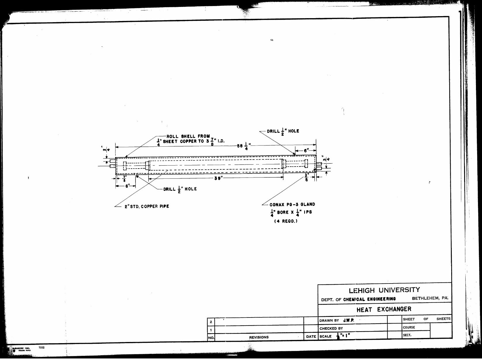
Plate 10: Excl:rnnger
I
..
... 26 •
ANINI IIIL 705:1 --·
.----ROLL SHELL FROM DRILL f" HOLE
l 11 SHEET COPPER TO 3 l 11 1.D.
~---:;r-----'------------->L-----'58 l "----~---------4
DRILL 1" HOLE 2
2" STD. COPPER pi,E
2
CONAX Pl-3 GLAND
!" BORE X i" I PS 4 4
(4 REQD,)
, ..•.. -·-··-~-~ .... _. !.. ..
LE~HIGH UNIVERSITY DEPT. OF CHEMICAL ENCUNEE RINI BETHLEHEM, PA.
HEAT EXCHANGER
DRAWN BY J;W.P. SHEET OF SHEETS
CHECKED BY COURSE
NO. DATE SCALE "• I " SECT.
(
11/ .,. . I
i .~
I
I J
1osi
3JOH II l JJlftO 9 11~CH~
ro i 11< i.·.
---------~:..-----__,..-" .!. ea"""'L~' --.. - --- --- ------ -------------.
.rr- ----- - _;.. -------·--' r"--------r•1 .
=l+--t--' :- . '-H --- - -I------- I II .:
1.r ,.1'" _ - - - - - ... - - ---··---- -- ---- ------ - --- ... - - - -~- ·-·-· -
_/
---------............................................. __ ._ ...... .
UIIIOJ!IGI trl!Sfl · r.J c --;-in. F: 1 ffJ\·1
.. ri ·'"· t ·-~, ...... , ..... "·-·-··· .. --.... ~•, .. <>.,,,,. ,, •. .-, .... ~, ""--···¥ .,-~-·- .. ·-•·<,. ..... ~·"7i
i
::1EAT NGER ~ 2
HI •"
.L-·
' ..... · ' ., .. ···-· -- -------·-····-·-........--... ~-· __ . _.· ·-· -'---Do
f
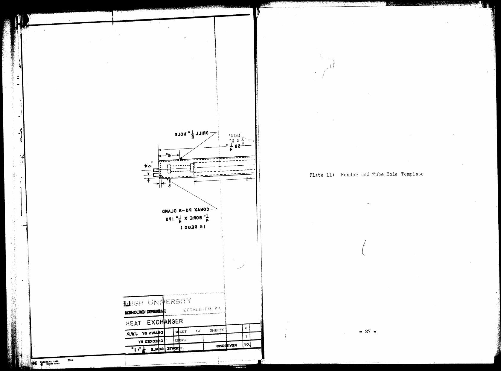
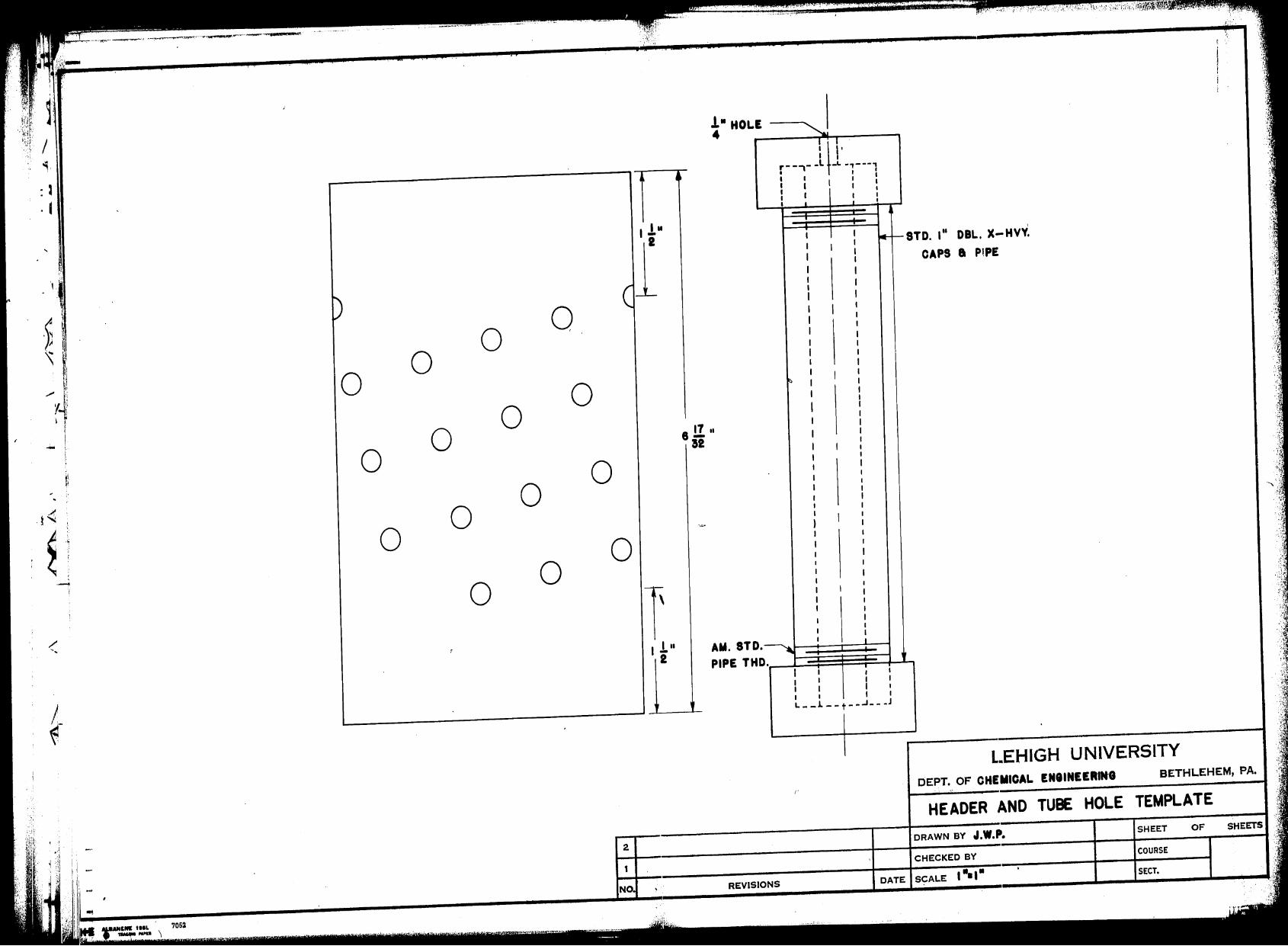
PlFJte 11: Header and Tube Hole Template
(
• 27 l!t
: J . f
A
t" ,.· ~· -!
D
0
0
0
7052
0 0
0
0 0
0
0 0
0
0 0
0
I I ! II
2
2
N
·: _-1.,: • .:r-.,. ".-. "
. ··--·-· .. ,...
-!• HOLE ~!
8 !! II
a2
AM. STD. ~ PIPE THD .
REVISIONS
.--,J lL---, : I I ;
I I l : I I I
I I I I I I • I
I
. ~'-STD. 111 DBL. X-Hvv:
CAPS a PlPE
) I
I
. I
I I : I
I I I I I I I I
I I I I
L--l--t--..J ___ J
L.EHIGH UNIVERSITY
OEPT. OF CHEMICAL ENIINEERING BETHLEHEM, PA.
HEADER AND TUBE HOLE TEMPLATE
DRAWN BY J.W.P. SHEET OF
CHECKED BY COURSE
DATE SCALE I •• ,. SECT,
:,.
~(: -~' . ·\t ')
"" ··.1 ;,,, . . ,·:~ . : ~

- ,, .) ... ~ ,-"7''.• .•.•
: J
jr·· ,.
t
0 0 0
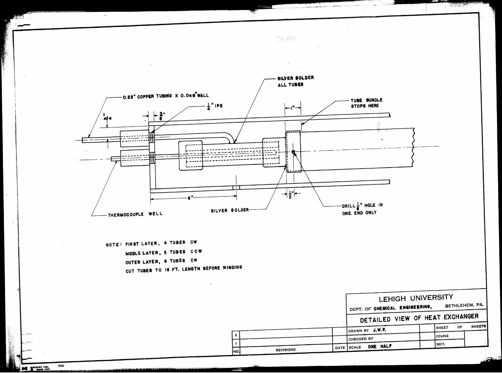
0 0 0 Plate 12: Dete.iled View of Heat Exchanger
~; 1· ·., 0 0 0 0
r 0 0
0
<
t ~
1-- -· - YTt-2H3Vi~U-HVIH3. \ .. 28"
.AG ,M3H3JHT38 (
·---~·---.. ----...----L-.. -------,-~-,-----
T!i3Hc
\
7052
,---- SILVER. IOLDER
ALL TUBII
,----0.28" COPPIA TUBING >C 0. 049.WALL
,---l"IPS 4
r-----· ----r·----· ------,
-----_J:-_-::- : :-_-::: :.:-:::.:::::: -_::: . .-1 ,- - - - .Lo----+-
t------1--t9----- ------------------ -----·J r----- -------------------- -----, L- --- -
- - ----.I
---r -e"--~
..___-THERMOCOUPLE WELL SILVER SOLDER--_,
NOTE: FIRST LAYER, 4 TUBES CW
MIDDLE LAYER, e TUB ES CC W
OUTER LAYER, 6 TUBES CW
CUT TUBES TO 18 Fi, LENGTH BEFORE WINDING
2
NO.
,'.<• ' '• I""-'., \•
REVISIONS
-- TUBE BUNDLE STOPS HERE
-----DRILL ! 11 HOLE IN 8
ONE END ONLY
LEHIGH UNIVERSITY
DEPT. OF CHEMICAL ENIINEIRINI, BETHLEHEM, PA,
DETAILED VIEW OF HEAT £)(CHANGER
DRAWN BY J, w:P. SHEET OF SHEET$
CHECKED BY COURSE
DATE SCALE ONE HAL, SECT,
t f. r i~-· w
/ /
I
I
l JJAw"e~o .o X 8M18UT RJCf'100 "a!.O
a cu r· l -----~ .. ij
--- --&-
r ·-----. ·----~---~- - - -----~ \·'
f. /. ;.·
I l• =-.::J::==:-=--==uiu: • - - - - - - --
.:..=..:::=-=: 1-- .... i - .= - - - =:- - I--+--
-·--,- - -1- -- -----~------·---,-- --r --- ---- - ,
. \ _____ J
\ ~
3Q.108--A3V.Jl2 l (
JJ3W 3J'IUOOOMll3HT _i 1
WO 838UT f. , R3YAJ TS ff Pl : 3TOH
WO~ 83 SUT e , ff3YAJ 3JQOIM
WO 838UT 8 ,R3YAJ R3TUO
HT8M3J .n 81 OT 838UT TUO
,,_ ___ , _____ 'Y"-_-,-___ .._,.. __ ~·
T:33HZ · "
32SIUO::> :
'
Construction
The location of the holes in the header for the
tubes can best be determined by preparing a template from
the unrolled view of the header. This can be rolled around
the header tube and a center punch mark made right through
the temple.te. The thermocouple well should be placed
through the header cap and silver soldered on both sides
of the cap before the thermocouple is inserted. After the
well is in place in the cap, the thermocouple should be
placed into the well and thejunction silver soldered into
the end of the well closing it offo The well should be of
such length that it extends ~t least three inches out of
the end of the heat exchangero The high pressure line which
is the inlet or outlet from the exchan8er should enter
through the Conax gland which is off center on the end and
feed into one of the holes in the middle of the header.
The headers should be silver soldered to the caps closing
the ends of the mandrel before the tubes Rre wound.
( '
The tube layers will be wound easiest .with the
aid of a wooden jig to hold the tubes 2t the proper spacingo
The tube layers should be wound in alternate directions as
eachlayer is wound over the mandrel. Solder may be applied
frequently to hold the tubes in place. Care must be ta.ken
to see that the small hole drilled in the mandrel at the
one end is not covered up. It does not matter which end of
the mandrel has the hole. When the tube layers are on, the
- 29 ... ·
' ,J
-. '
r . :·. J
L
- c~ -
I'
tubes should be cut to the proper 1 ength on the ends and
silver soldered into the holes in the header.
Roll the shell to an I.D. that gives a snug fit
when the tube bundle is inserted into it. Then the seam
should be soldered shut with silver solder. The end plates
on the shell containing the Conax glands should be soft
soldered in place in order to allow for their removal in
case the exchanger needs repair.
- 30 "
., )
\:, .,
• ,I
. . . (' '
. .
... C' . -
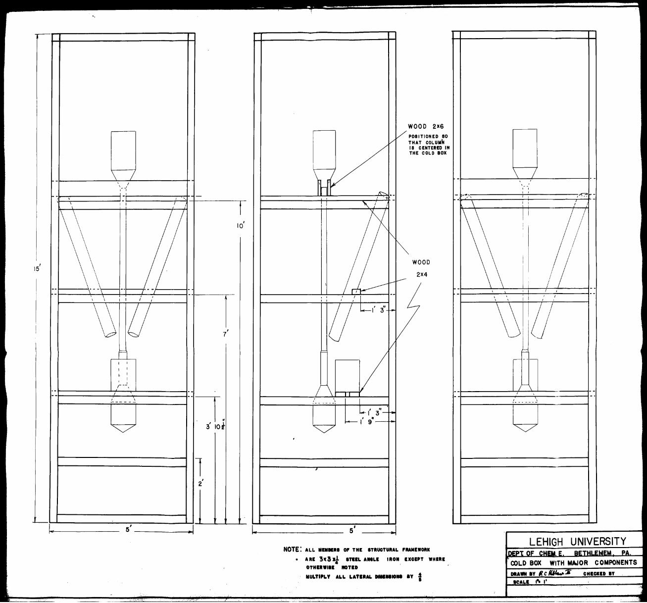
COLD BOX
Design Principles
In order to calculate the heat loss from the cold
box apparatus, the complex shape of the column and othEI'
apparatus was a.pproxime.ted by a cylinder with a. length equal
to the column length and a radius approximately equal to
tlbte average radius of the apparatus. The total heat leak
was calculated from the allowed heat leak of 3 BTU/lb. of
air handled. A correction was subtracted from this heat
leak to allow for conduction through the valve stem ex
tensions and heat leak through the ends of the box. Assum•
ing the outside of the cold box was at room temperature and
cylindrical in shape, its radius was calculated from the
allowable lateral heat leak. When the outside radius was
determined, the cold box was squared off to form a rectangle.
- 31 -
...
t '< 1 f.' ,',
r
/l. ~
Plate 13: Cold Box With Major Components
(
.. 32 ...
-'
._ _ \ I I I
\
I - -, ~- I
\ l~J I ' ·- -I
\ I I I I
t ,
IQ
I 5
-- c·, --,.._ •• -I ---' I ,
I I I I I I I
~ u I
7
=1
I I
I I
1- I
I I
I r--, . - . -I --
I \ --
-i. - -
~ I
IOt 3
1 I
2
-5'
I
0
IN
WOOD 2X6
POSITIONED 8 THAT COLUMh 18 CENTEIIED THE COLD BO X
' I I ,----·-,
s'
( 3" I 'f
I 9-~.l
.. 1
WOOD
2X4
NOTE: ALL IIIIINH o, THI ITIIUOTUIIAL ,RANHOIIIC
~ AIII 3ic3 xi ITIIL AHLI IIION IXOIPT WHIIII
OTHIIIWIII NOTID
IIULTIPLY ALL LATIIAL DIIIIHIONI IY t
-- , .. ,
' 'I -. \
~-I -
I
----
\ I . -I
, I
, - -
I I
I I
I , ---!::" --
I I I
I I I
11
!
I
- -I I I , --I , I ' I I I ' I
\S i?J -~
- __ ,_
/~ \ --I --
f--·---~
~
WITH MAJOR COMPONENTS
C R:Ma,.,.:6 CHIGHD IY
•, ! ' ·'
<
I! ,.i
i I i I I
1L. ~
\ . \
f .-,, .... ,,,•·,.-.,.., ·-•,·,· ~ ~.-·;,, ,.>•·•·· • ~•' .• ~ •. .,,., • ._,. -u~-1. .•• , .. ,,,_.~·'f""l·'•~'....,~..l. ,-:,.,·?.,,._.:;:
r-'
j \
QI
.J;
\
'/ .. ~1.i·
~.,-:---
I
! ,:, ..•• ," .,~ •.... ,
,~~·
Construction
The cold box is to be constructed by welding the
iron frame together and bolting on the plywood panels to
retain the insulation. When the frame is first constructed,
the cross pieces on the south side of the cold box should be
left offo This will permit the column to be suspended in
the cold box. The column is suspended at the top only
because of the expected contr~ction of the column as it
approaches oper8ting temperatureo Care should be taken in
the suspension of the column that the column hRngs vertical.
The back panel should, of course, be put on before the frame
is shoved against the wallo
The heat exchangers are shown in Plate 13 as being
slanted out, one into the southwest corner and one into the
southeast corner. The warm end of the exchangers is outer
most and the cold end is in toward the colmnn. After the
main components are installed and piped together, fue final
valve locations will be determined exactly. Then the proper
holes should be drilled in the operating panel, the west
wall of the cold box, for the valve stems and manometer leads.
In addition, a hole should be made for the thermocouple lead!
in this wall. The product streams from the apparatus, which
include a liquid nitrogen, a liquid air, a liquid stream
from the bottoms, and two gaseous streams from the heat ex
changers should all be brought out the west wall. The high
""33 •
• I.
., .,
r .
,· r
r·
[' ,-.) .. ,: ; , ) _:. .. . ~ . .
I .
C r : . (' .,
pressure air from the pre-cooler should be brought in the
north wall, The south wall should have nothing going into
or coming out of it, This will leave it free to be removed
if repair work has to be done to the column, Although the
panels on three of the walls cD.!l be put on full size, that
is 8 1 x 4 1 , the south wall should have a section two feet
high at the bottom, followed by a section 6 ft, high. This
can be made from the 8' x 41 panel by cutting it across two
feet from one end, Should the insulation have to be removed,
the bottom section can be unfestened and the insulation will
flow out where it can be handled by shovels.
In order to fill the cold box, the walls should
be put in placeo Then the insulation, Sa..."'1.toc el, can be
poured ino It would be easier if the box were filled up
ton height of eight feet and then the second set of ply
wood panels put on and the rest of the insulation put in.
'l1he four 1 1 x 4 1 strips left over from the sides can make
a top for the box, Care should be t e.ken when filling to
see that the insulation is evenly distributed and that the
column is not moved from the vertical,
The piping of the apparatus in the cold hox is
exactly as is shown in Plate 1, All the 3000 psig lines
have 1/411 needle valves while the remainder of the lines
have 1/211 needle valves,
• 34 ~
r.
' j
t '.
'
, r
~ ,,,, ,, J". / ' ·'' ,.i.
(' ' -:/·
.d-.,-...,_•···· ·---~--... --,··---,. .. I
The walls of the cold box should be made as air
tight as possible. This may necessitate packing the joints
in the box with a sealant. This is done to prevent both
diffusion of water vapor into the cold box and leakage of
the powdered insulation out of the cold box.
• 35 ...
\ .. {
')
.., . - '
• ,· • .... : •. !,.
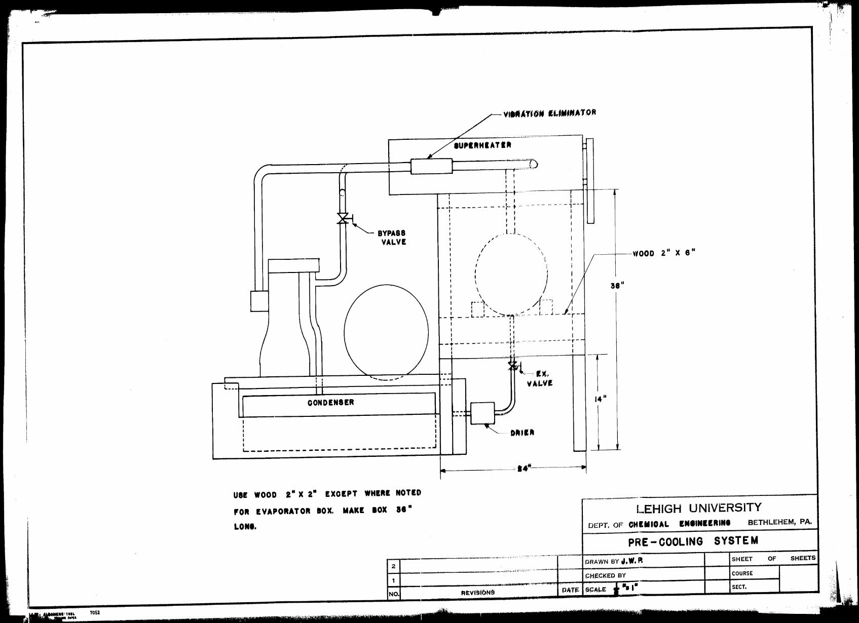
PRE-COOLING SYSTEM
Design Principles
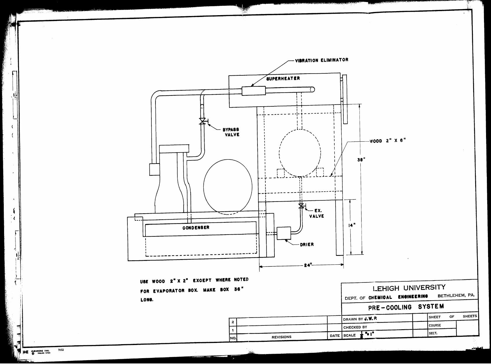
The use of a pre-cooling system is desired in a
low temperature unit because the added refrigeration
increases the yield of liquid producto Since the Chemical
Engineering Department has a Freon refrigerator compressor
available, it was decided to employ this in a pre-cooler
using a standard vapor recompression cycle.
Since it was desired to always operate the system
at a positive pressure, the suction pressure was set at a
minimum of 15 psia. It was considered that the maximum dis
charge pressure the compressor should develop would be in
the neighborhood of 160 psia. A search was conducted of the
available refrigerants and light hydrocBrbon gases to find
one that would produce the lowest temperature Rt 15 psia.
and still be condensed by the coollng water at S0°F. The
refrigerant which best fitted these conditions was found to
be Freon-22, which boils at -40°F. at 15 psia. and is con-
o densed at 80 F. at a pressure of 159 psia. Of coi,µ1se, if a
lower cooling water temperature is available, th~ discharge
pressure can be reduced accordingly.
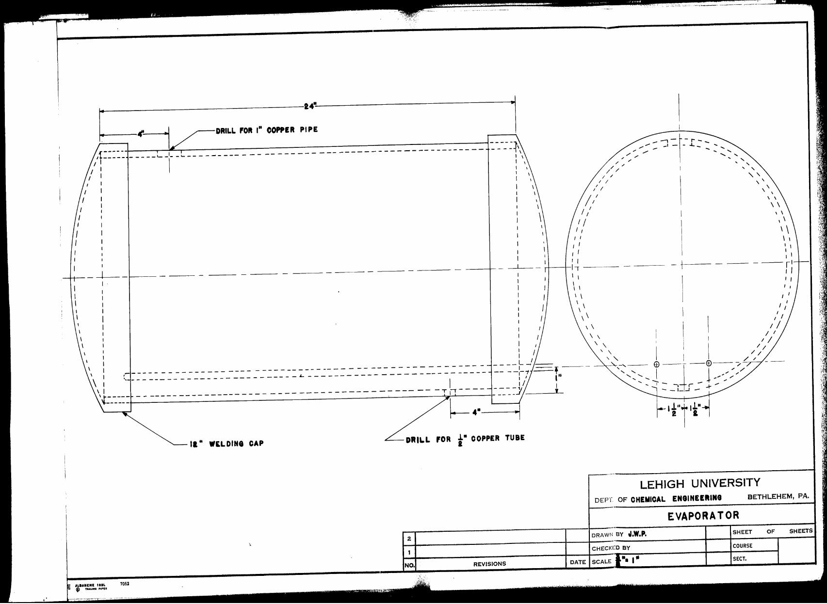
After the refrigerant was selected, an evaporator
had to be designed to cool the air. A search of the litere:,,,,.
ture revealed that little date was available on boiling heat
"36 ...
I , ~
f
_, -l. ,)
i,
('
t
_[c
, r
transfer coefficients for Freon 22 (F22). Some data was
available, however, for Freon 12 outside tubes (4). This
data indicated that the coefficient ranged from 200 to 800
BTU/hr.°F.ft2 depending on the temperature difference and
the boiling regime. For the purposes of this design a
value of 15:J BTU/hr.°F.ft2 was selected as the outside
coefficient. The inside coefficient was calculated by the
use of the¢ factor discussed in the section titled Heat
Exchangers.
The evaporator was rtesigned to cool the Pir from
0 0 100 F. to -20 F. Knowing the he8t duty, complete enthalpy
data on F22 (5) enabled the circulation rate required for
F22 to the evaporator to be determined. This circulation
rate was calculnted to be about ten percent of the circu ..
lation rate the compres3or was capable of performing. In
order to use up the extra capacity of the compressor, it
was decided to put in a bypass between the compressor dis ..
charge port and the entrance of the vapor line into the
superheat er.
The refrigerant charge was calculated from a
knowledge of the liquid and VRpor volumes of the refriger
ant in various portions of the refrigerant systemo
- 37 -
. ---~ .~ --·~,- . . . - '·.'-. ;......i_
·.~ .. i.,') ti
~i ~ /.,
' k. L ;.· l ..
r r i:.
,·
" 1 . . ,. ~ l· :;
( :r. !;: !e.
f f ~, .• 1 ~;: t'· •,; 11,,1,,
'-
r .1 ll
)
[ \
\
Plate 14: Pre-Cooling System
' I
~ I
r I
<I •
1!. ~ 12 ;
I I
t. ~
(
.. 38 •
:,•,·:·.·:,··. •, ,,. ,_,. ,,.;.,. ,,,,,
i'.'
t ·r ' fl.
[
r I
<I i I.. '
I~! I I I I
,.L : ~ I
I,
AL8ANINI IHL 7052 • fUC.IIICI ,A•I•
,,,
I I
"- BYPASS VALVE
----------: I t. ••• J---------++--------------,
I I I I I I
OONDINSER
'-------- - - -- - -- - - - - - - -- ------ _.J
VllflATION ELIMINATOR
I I I
I I I I
- - - - - - - - - - - -1- t - - - - - - - - - ,--1 I I I I I
... 1.1_ .. ... ; '
I ' I \
/ \ I \
I I I I
I I \ I
' I \ I r· • ~ /(- . . ,
I 1' I
: I I ', -" I 1
_ ,- - -L--'- --""=9ii-:..~- -L-.L-1 11 1, I 1 1
I
I '1 I I I
-'t'-- - --- - ---H---- -------r-1 1 1 I
1 I: I
EX. VALVE
DRIER
~----WOOD 2 11 X 6 11
!8"
T 14 11
----~ -2411
-~
USI WOOD 2" X 2• IXOIPT WHIIII NOTED
,011 IVAPOIIATOII IOX. MAKI BOX al"
LONI.
2
, NO. REVISIONS
LEHIGH UNIVERSITY
DEPT. OF CH!MIOAL INIINIIIIINI BETHLEHEM, PA.
PRE -COOLING SYSTEM
DRAWN BY J, W, P. SHEET OF SHEETS
CHECKED BY COURSE
DATE SCALE .. ,. SECT.
"' .. '.'..·. f' 1/·J, ' -\\
'-"i'.
'{ '----. <,
•(:i, ' .st.:: f: ' .____.._.......---.---
~ ' {!. i.---'"-~-----.;,,.• ----------
lr
,, '"
r • f : l ' 1138M301100 :
f' ,1 1 1 t ,
f , 11 : l 1 : .• - _...1. r --t -------------------..J
.• n, q , fvL:! r-L:U HT.:lt:l 'I
[ •-.., ... ~"'l"-"~'""''•~ .. --.0.•u••••"• ,«•- --··- -•••-,.,,...,,,.._, .. ,..,...._ ..... , ..... - ...... ,, ____ ,.4'_, ...... .,, .... ~.••••
:'i. .. :,·.: i' ~~.'. ',t ,,,,
" __ ,.._._ ....... ~-• .o;, ... ,,,.,., ..... ~ .... ., ·--- .... ~- ·-•·&:··--··· ... ----·'········ ··-T33H2
_...._,,, ............ .---t-~--+-·--· ,,..,._.,, .......... """"~'''-.T:>32 Rao\' JIit IIIIIIAIJA
R-1-T •
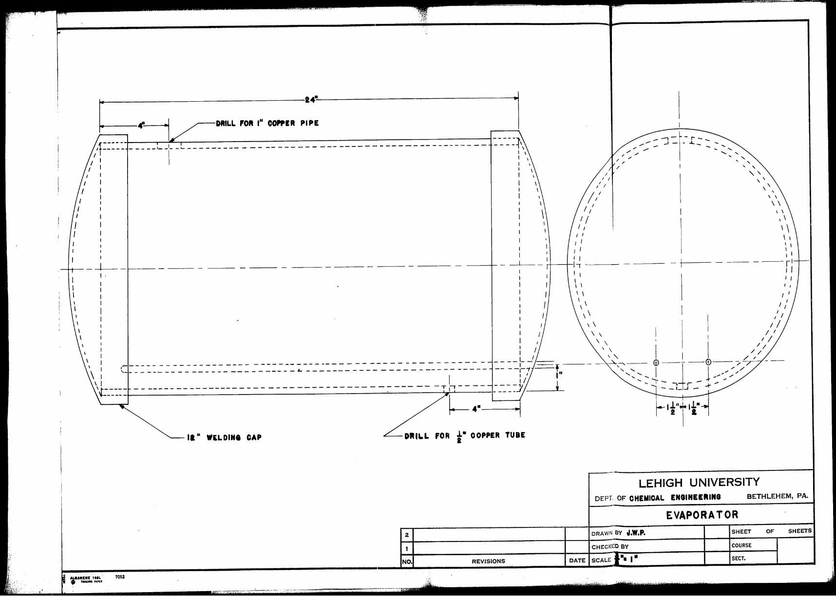
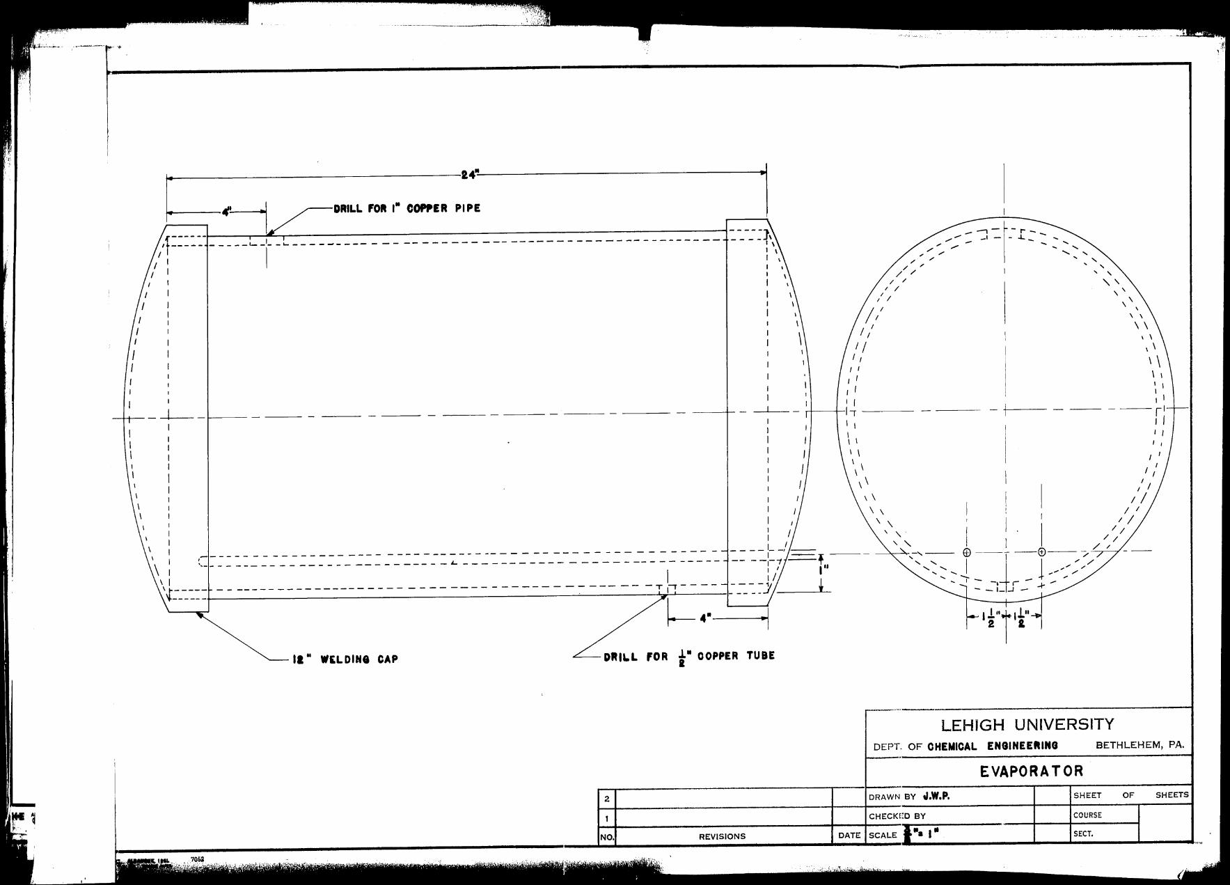
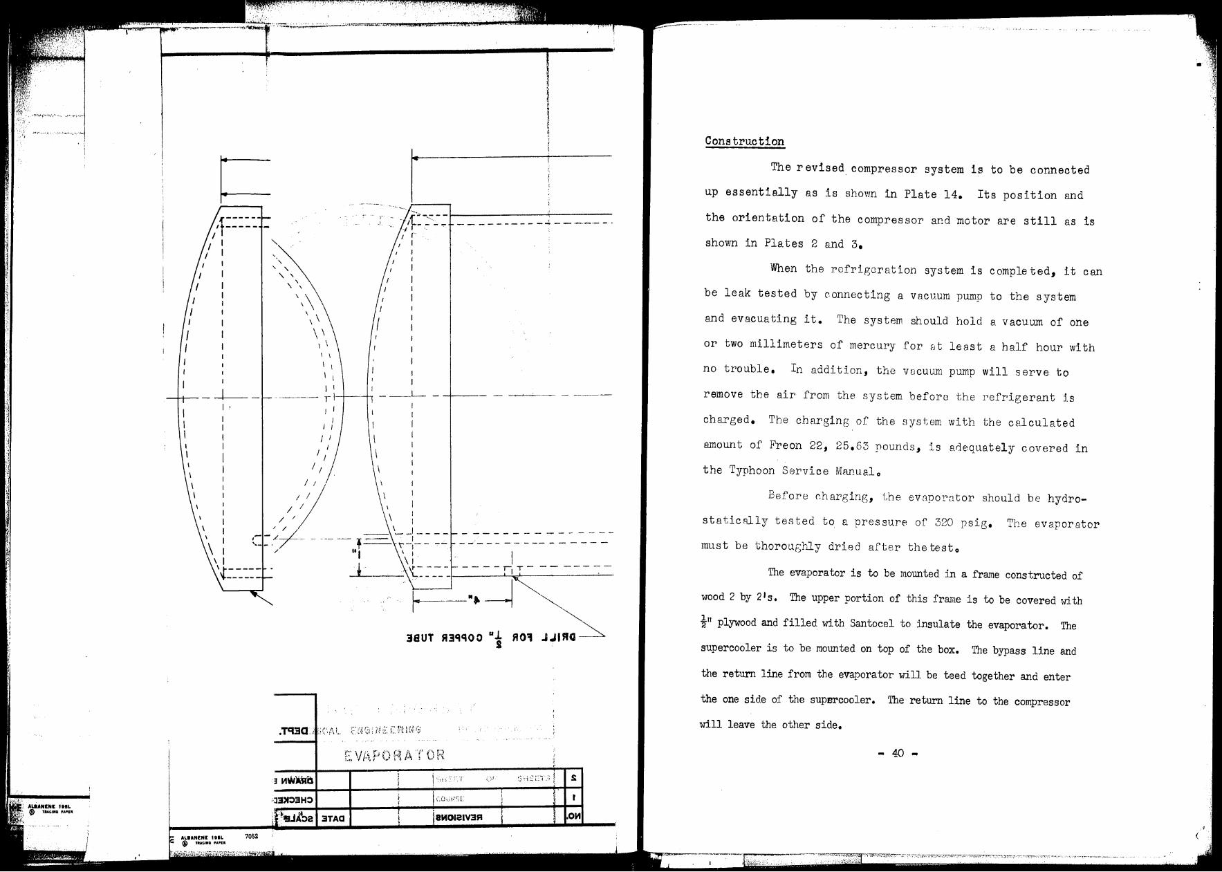
Plete 15: Evaporator
"' 39 ...
J
',. · ..
~-:-_-__ -_-_ -,-~----~~~-D-R-IL_L_,_0_11_1_" _C_O_PP_I_R_P~::"-----------------~1 /t----- --- --~-i- -~ -- ---- --- ----- ----- ---- ---------- -- -- ------- -- -::_-_-::l\
I
--- - ---- - ---
I I I /
\ ,- - - - - - - - - - - - - - - - - - - - - - - - - -- - - - - -- - - - - - - - - - - - - - - - - - - - - - -__ - -_-_:I-_~,-· :=:=- I"I ''
, .. _ - - - - - - - - - - - - - - - - - - - - - - - - - - £.. - - - - - - - - - - - - - - - - - -- - - - - - - - - I T
\ 1/
'.~----- --------------------------------------------T-.,---- ----1, I
-+-------'f---------------------------"--------':;;rl_.__ ·---,- -- - _J t
II.. WlL DING CAP
ALIANINl 1HL 7052 f 1Ut.lNO PA•UI
f-4·--- DRILL FOR .l.• COPPER TUBE
I
2
NO, REVISIONS
_--,-1-r-.,,,,..,,,,,,,,. _, - - .J... _ .... ...... ,, ..-- ...... ......
/ / .. ..... ,; / ..... '
/ ~ ' ' / ,;
' ' / / I ' '
/ ~ ' ' I I
\ II
\ I
\
// 1/
I I I I
1J.nr1.L" 2 &
LEHIGH UNIVERSITY
\ ' \ \
\ \
I I I I I
r1 I I I I
DEPT OF CHEMICAL ENGINEERING BETHLEHEM, PA.
EVAPORATOR
DRAWN BY .,,W,P. SHEET OF SHEETS
CHECl<t:O BY COURSE
SECT,
~t 1
t r- 1 3'11'1 1131"00 •• R01 JJIRO ,~ ______ :
·c I . I ______ _, __ , __ , _____ -----t\
'lt ' I \
[ . ! I \ \
- .
\
'·
\ \
\ I
;
-- --;- - -·--- -- - -------- - _J_ - ----,f-+-
/
' I
I
I I I
~ - - - - - - - - - - - - - - - - - - - -.., I
----....!--------------I
[-~-::: t = = ==: = = =---:: _-:~-----~=----=========-~:::Ji - 1
',i ! I ·-' ·I .-.
14 I ~
qA~ 8HIOJlW ••JI~
... ..,.. ........ --.. ... -.... .... __ ___ ·-------· ... ······-· -----·· -·-···----t·--~--
T:3JH2
J2f!Uo::, Yn a
&I 0 . I ~,~ .:!\.
------------·-·- -·-- ··----- ··-------,.·-·-·•»·'-""1 Rttiatz:J e
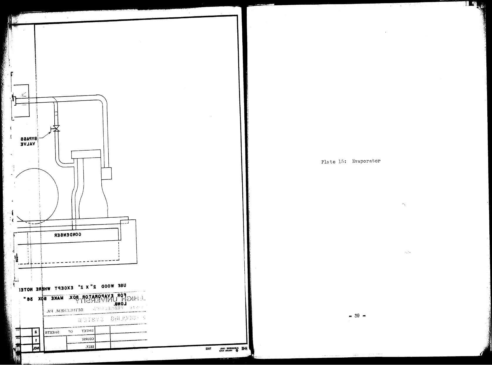
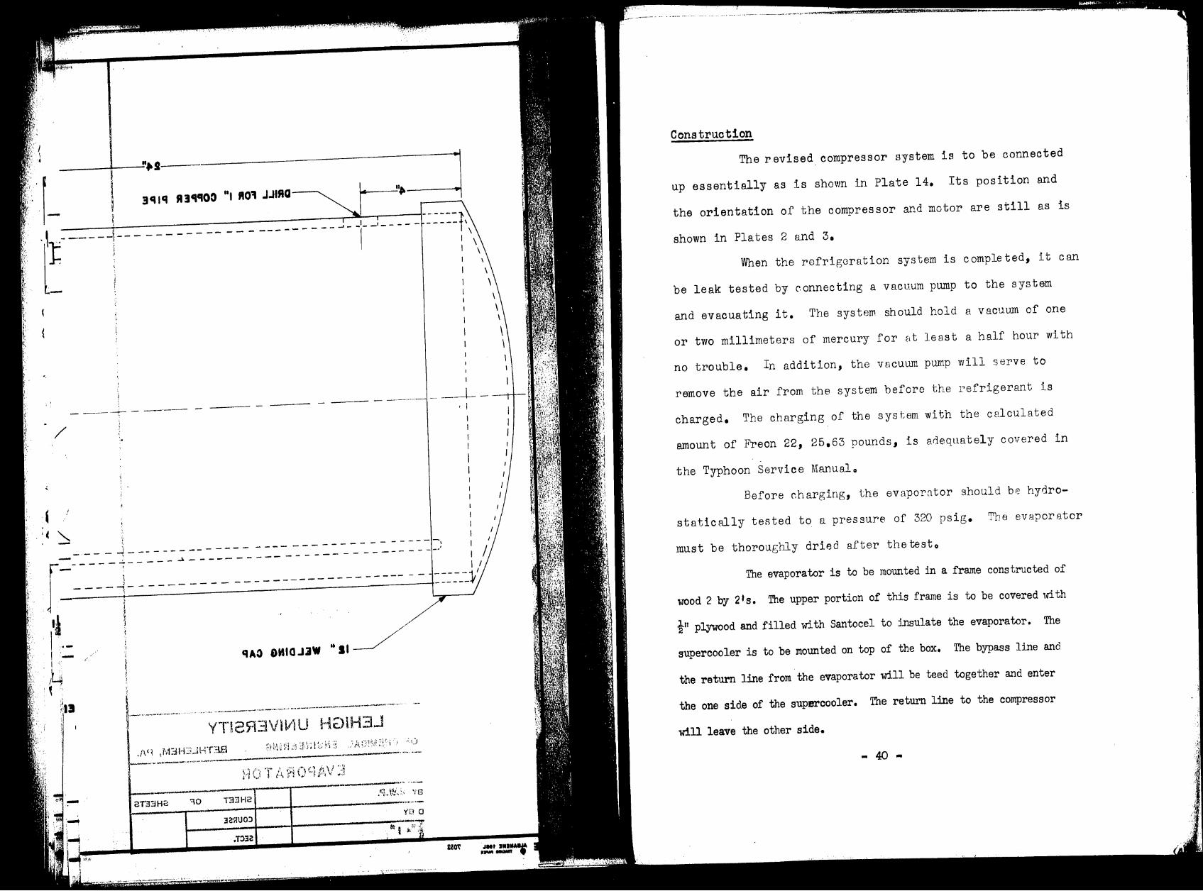
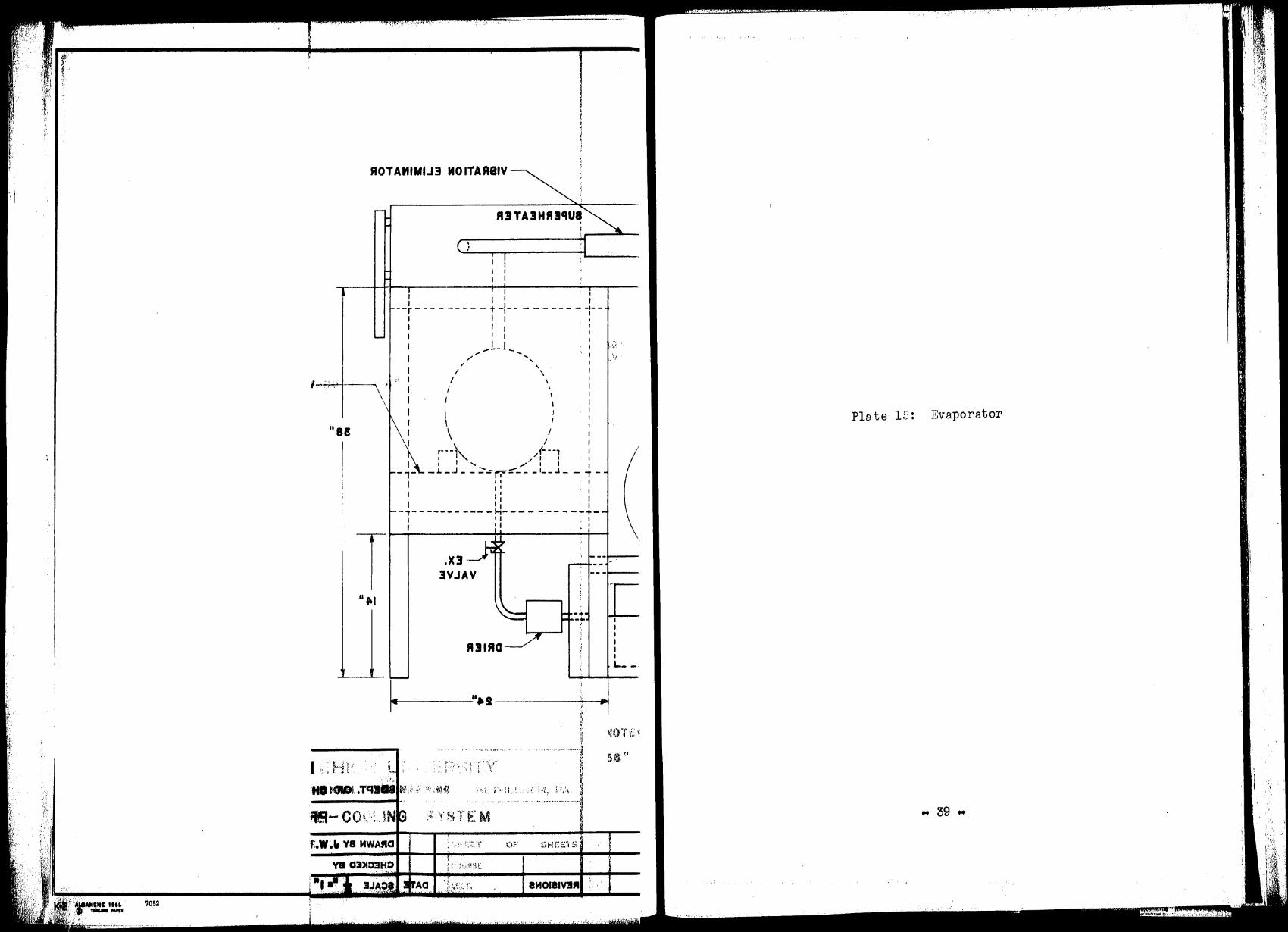
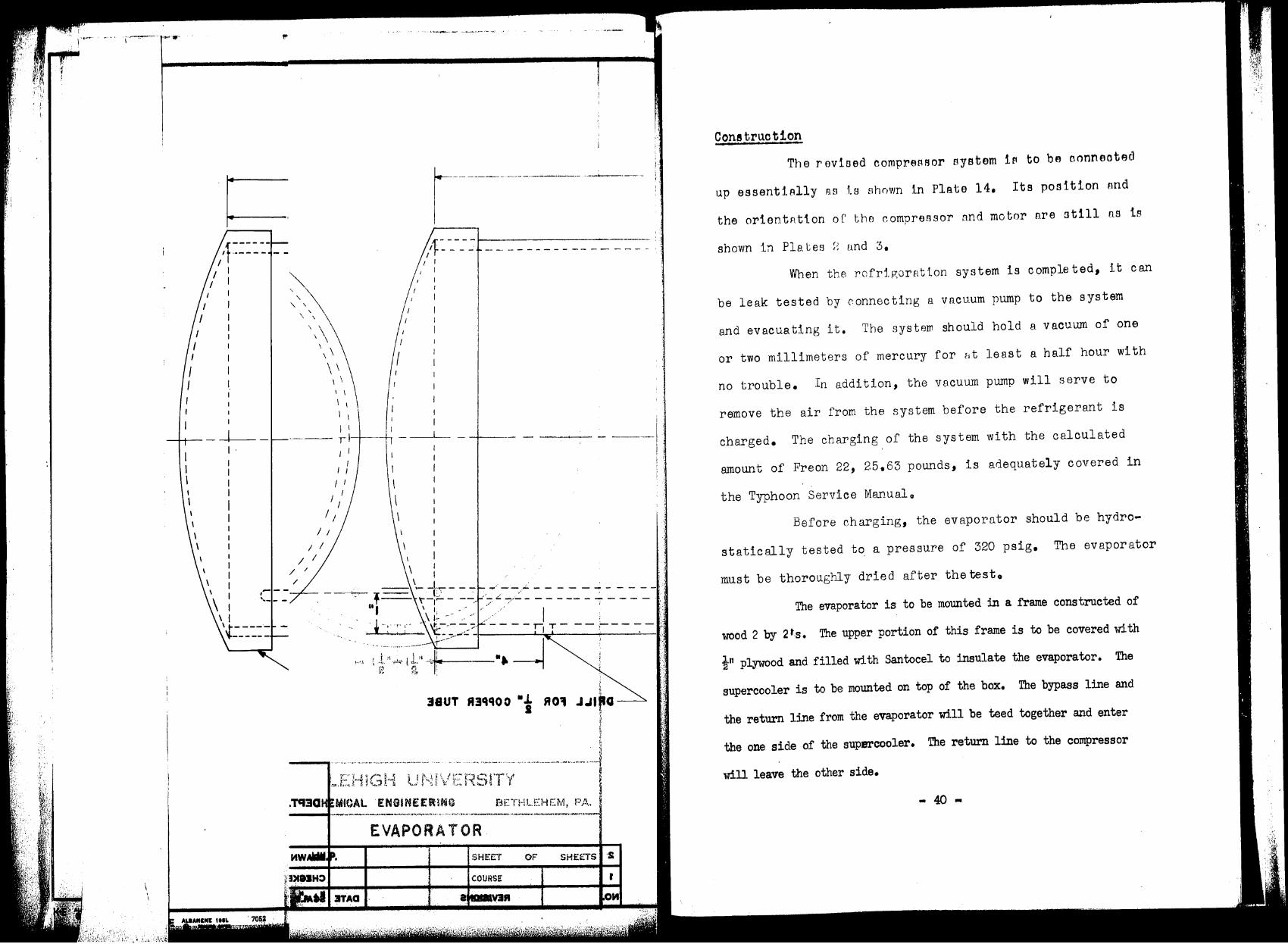
Construction
The revised_ compressor system is to be connected
up essentially as is shown in Plate 14. Its position and
the orientation of the compressor and motor are still as is
shown in Plates 2 and 3,
When the refrigeration system is completed, it can
be leak tested by connecting a vacuum pump to the system
and evacuating it. The system should hold a vacuum of one
or two millimeters of mercury for at least a half hour with
no trouble. In addition, the vacuum pump will serve to
remove the air from the system before the refrigerant is
charged. The charging of the system with the calculated
amount of Freon 22, 25,63 pounds, is arlequately covered in
the Typhoon Service Manualo
Before charging, the evaporator should be hydro
statically tested to a pressure of 320 psig, Tlrn evaporator
must be thoroui;;hly dried after the testo
The evaporator is to be mounted in a frame constructed of
wood 2 by 2 ts. The upper portion of this frame is to be covered with
! 11 plywood and filled with Santocel to insulate the evaporator. The
supercooler is to be mounted on top of the box. The bypass line and
the return line from the evaporator will be teed together and enter
the one side of the supercooler. The return line to the compressor
will leave the other side.
- 40 -
,' . I I I I I I
'--------,.....------f.-t-· t I :,
I 1
"-- BYPA88 VALVE
......... ____ .,,,,...-
', I L ••• j....--------i-+--------------1
OOND1N8ER
I I I I
I I
I I
'-------- - - - -- - - - - - - - - - -- - ----- _.J
UIE WOOD IN >C 2N EXOIPT WHIIII NOTID
,011 IVAPOIIATOII BOX. MAKI IOX II"
LONI.
I I J .I - - - - - - - - - - - --}'- -t ~- ., - - - - - ., - ,- -
I
I
' I
I
I \
I I
I
I J I
1 i I I I
,. .. LJ_-... "" "
\ \.
~. Ii
: r--\, /(---·: I : I , ,, I 1
) I L : '-....__<I\·•-<- - --!--- -'-- -r-
- T" - - - - - - - - -, ' .. I , I t
I : 1 I
I I I t I .. _tj ---· -------r--r- - ---- ----r I,, . ,
----WOOD 2 11 X 6 11
38"
I 1 1• I
-- ·=--v.--t!·-,,-~-T 14 11
- .. -·--·-------------------------1 L.EHIGH UNIVERSITY
DEPT. OF OHIMIOAL INIINIIRINI BETHLEHEM, PA.
PR£-COOLING SYSTEM
-.....------------··--·--············ ········---·------...----1-----------------r---------t DRAWN BY .J, W. P. SHEET OF SHEETS
,__2....._ ___________ · ......... · - -·--+------·-------t---t-----,,-----1 CHj::CKEO BY COURSE
.._...._ ______ ..__ .................... ____ .,,_. • .....,...,....,,41,...-.,....... ........ _____ !""'"I-I~• ·-------+----f-SE-C-T.----t
NO. REVISION§ PJffl='. ~~AI.-E
,, ,F
'7052
ROTAMIMIJ3 MO ITAflllV
I
: I I I --r - - - - - - - - - t -1- - - - - - - - ~ ---
"8!
T II J.I
~
R.W .I, YS MWAAa
va a1>1:::>3H:>
:•, .-,
I I
I I I I I \
,, ,,.
/
I I I I I I
.,.Ll_ ' ' ' \
\ \
I
I I I
I I
r··-\ (- --, I l ...... / f I I I " .,,.,. I I
- .L - .J - - .:::-..:- f'i"' ;::""_ - - '- - .J - - ' -' I I
I 1: I
I I I I , , . I
- 'T - - - - - - - - - - - H- - - - - - - - - -1- -I 1 1 I I • I ' I
.X!· 3VJAV
•'!' .... I
R31f10
"J.!
....... ,J ~
:; i. ··ri··· "~{,.· t1
r o(/ 1~1)',~ i ': ,'.~ T!·i L.1:'. ·, ,:: h•1, i ·•/~. j
................ ,. ................................ , •• 1
,~, y i;.·, ·r r.:·· u t 1 ,; ·\) t, K:r. b"\10
OF
' Aa ,,}:'-.:~> i·, 8MOl81V3fll ; · .
I I I I I I
L -·
Ple. te 15:
, '', ,,,.:1·····'
Evaporator
.'\
"' 39 "
~-~----------,-1----~~~-D-R-IL_L_f_O_fl_l_" _C_O_PP_E_R_P~::·~---------------____.1 /f----- -----~-1- -~--- ------ --- -- --- ------ ------- ----- --------- --
/
// 1/
I I I I
I I
I I I I I I
_--,-1-r-.,,,,""""' _1 - - J.... - -.. ..... .,,,,. -- ....... ......
/ - ... ' ; / ' '
/ / ... ' ; ' '
I / I , ,
'\ ' ' ' ,, ' \ \
\ \
I I I
........__,_I,~~~-I I ,,
I I I I I
11.}IIANCIH IIIL ' • tllMIIII , .....
I ,- - - - - - - - - - - - - - - - - - - - - - - - - -- - - - - -- - - - - - - - - - - - - - - - - - - - - - I
I
I
I
I
,,__ - - - - - - - - - - - - - - - - - - - - - - - - - - ~ - - - - - - - - - - - - - - - - - - - - - - - - - - - -=-= ~-=-:=;· -f
7052
I I / I" 1/
+------------------_-_-_-_-_-_-_-_-_-_-_-_-_-_-_-_-_-_-_-_-_-_-_-_-_-_-_-_-_-~---------_-_---'T,~'--'-----------1:~~~y t
II.. W,L DINI CAP
'1,1 ri::-,-.........-:"1., .. ' .. ·, • .; ·" · .. ; · ....... ,,·.·."·"
~4•-
"---- DRILL FOR .1.• COPPER TUBE a
2
NO. REVISIONS
' I I I I I \
\ \
'
I I I I
\ \
I I 1/
I I I /~~/ ©-----© /
, I J 1 .......... " ;,,/ ' - .,, ..... 1---, .-- .,,,,,,,. - _ ,_...1 - ..j,-
1.L .. r,!.· 2 I
LEHIGH UNIVERSITY DEPT. OF CHEMICAL ENGINEERING BETHLEHEM, PA.
EVAPORATOR
DRAWN BY .,,W.P, SHEET OF SHEETS
CHECK[:O BY COURSE
SECT,
' I .,,
I I
~ /t:::::- - -
~ ' \
'\ ' \\
\\ \ \
\
\ \ \ \ I I
I I
I I
I I
C .... ,,....J'M!.---- --· ~- .. -,-~ ~ ., .. , .•
I
---- 1 l~--1-. ____ ,___ - ------
I I I
I I
I I
I I I
I I
I I
I I I I
/ /
/ ---, --, ___ -
. TCl3Q
I
I
I
;~
38UT f13qqo O • t R 01 J .Ura _ __,.
EVAPORATOR
SHEET OF SHEETS ·S
COURSE r
I· I·
Conetruotion
The revised compreARor system 1~ to be oonneotad
up essentiAlly nets shown in Plate 14, Its position ond
the orientAt1.on or tho compr•essor nnd motor nre ntill ns ts
shown in Plates~ und 3,
When the rofrtgorHt ion sys tern is c omple ted 1 it can
be leak tested by connecting a v Rcuum pump to the sys tern
and evacuating it. The systern should hold a vacuum of one
or two millimeters of mercury for Bt least a half hour with
no trouble. In addition, the vacuum pump will serve to
remove the air from the system before the refrigerant is
charged, The charging of the system with the calculated
amount of Freon 22, 25,63 pounds, is adequately covered in
the Typhoon Service Manual o
Before charging, the evaporator should be hydro-
statically tested to. a pressure of 320 psig. The evaporator
must be thoroughly dried after thetesto
The evaporator is to be mounted in a frame constructed of
wood 2 by 2 ts. The upper portion of this frame is to be covered with
}" plywood and filled with Santocel to insulate the evaporator. The
supercooler is to be mounted on top of the box. The bypass line and
the return line from the evaporator will be teed together and enter
the one side of the supercooler. The return lille to the compressor
will leave the other side •
.. 40 ..
I
,, '
. ·--···-----····----- .:1
r i.----6'.~--24·~---1 ~ ,. I --DRILL ,011 ,. COPPER Pl PE
"'------'t-- --- - - - -- '- _1_ - I- - - - - - - - - - - - - - - - - - - - - - - - - - - - - - - - - - - - - - - - - - - - - - -
// 1
I
I I I
--- - ---- - ---
------ -- -------- ----\ :
, , .. _ - - - - - - - - - - - - - - - - - - - - - - - - - - L - - - - - - - - - - - - - - - - - - - - - - - - - - -
\ I '..J:" __ - -- - - - - - - - - - - - - - - - - - - - - - - - - - - - - - - - - - - - - - - . - - - - -
f.-4•-, 11 11 W&:LDING CAP DRII.L FOR t• COPPER TUBE
2
NO. REVISIONS
_ __,-,-r--.,,,,,,,,..,,,, -· - - ..l.. _ ........ '
,,,,,,. _.. ' ....... / ..... .... '
.,, / ....... ' / / ' '
/ / ' ' / / I ' '
/ / " ' I / \
II ' I \
// '\ \ / / \ \
I I I I
I I
I I
I I I I
r+----+--1, ~---
\ \
\ \
\ '. ' "
,1 .. r,.L .. 2 &
LEHIGH UNIVERSITY
. l.~-.t"•_...
I I I I I ,1 I I I I
I I
DEPT. OF CHEMICAL ENGINEERING BETHLEHEM, PA.
EVAPORATOR
DRAWN BY J.W.P, SHEET OF SHEETS
CHECKE:D BY COURSE
SECT.
' ~ ,)<
1.
' ; 1•:
i
... ,, ...... ····~~-.. ,. · I
I I I
\ \
' ·, ' ' ' ' ,\
\\ \ \
\
\ \ \ \ I I
I I
I I
I I ----- , 1·-+----t,
I /
I I I
I I
I I I
I I
I I
I I
I I / /
I :· .:. . _/t~ ~;~~-:
r I I
- - - - - - - - - - ..:;. - - ·-·-·- - .
/ /
,- - ,L , ___ ' \ ---------------.. - -- - -- - 'I ~- ,_ -, -- - - - - - - - - - - - - - -T \""-,- - -,-- - - - - -
'.t-- ---- . ~------
7052
/
,:J3>1:>3HO
" I \ I
_L--'-_'t:: :-.:-:. -_ - - - -:,~ - -- -: -
r-··-~ ,~ 38UT 113qqo:, "'i 110'1 J.11~
! ':,,,c::·.T
r
jeMOl21V3R OM
Construction
The revised. compressor system is to be connected
up essentially as is shown in Plate 14. Its position and
the orientation of the compressor and motor are still as is
shown in Plates 2 and 3,
When the refrigeration system is completed, it can
be leak tested by connecting a vacuum pump to the system
and evacuating it. The system should hold a vacuum of one
or two millimeters of mercury for at least a half hour with
no trouble. In addition, the vacuum pump will serve to
remove the air from the system before the refrigerant is
charged, The charging of the system with the calculated
amount of I<,reon 22, 25,63 pounds, is arlequately covered in
the Typhoon Service Manualo
Before ~harging, the evnporntor should be hydro
statically tested to a pressure of 320 psig. The evaporator
must be thorou.f~hly dried after the testo
The evaporator is to be mounted in a frame constructed of
wood 2 by 2•s. The upper portion of this frame is to be covered with
!11 plywood and filled with Santocel to insulate the evaporator. The
supercooler is to be mounted on top of the box. The bypass line and
the return line from the evaporator will be teed together and enter
the one side of the supercooler. The return line to the compressor
will leave the other side.
- 40 -
AIR PURIFICATION AND COMPRESSION
In addition to the three main constituents of
atmospheric air, there are present quantities of water,
carbon dioxide, hydrogen, hydrocarbons, and rare or inert
gaseso These impurities, although present in small amounts,
can accumulate in low-temperature apparatus and cause in
efficient if not hqzardous operation. Therefore, they
must be removed or the npp~ratus must be designed to mini
mize the effect of their 9resence.
Hydrogen and the rare or inert geses are extremely
difficult to remove efficiently. Because of their low
boiling points they will always remain in the ~aseous state
in this apparatus. Therefore, if the design is such that
they are not allowed to accumulate in any location, they
ci:in be allowed to reMain in the process streams as their
concentration will not build up to a harmful level.
Water can be removed by mecttmicRl means such
as regenerators or switching exchangers or by chemical
means such as solid R.dsorbents. For an apparatus of the
size and purpose proposed here, R solid adsorbent seems
more suitable. 'rhe regenerator becomes more economical ~-n
large plants which have more refrigeration to spare. The
switching exchanger•s require a.ttention of the oper•ator
during their cycle. The exchangers being switched and
... 41 •
. ,~~:;!,":,.I"',ifl ~~~~~';~r."".°7;",~~~.r;.-0~?,::;'.:;-;'•~~,-:-::~_:.~;'l~'i".~;';"'·;-_;r,: •:··,T; r~~-;,.~ ~~-, ,.,,,.. ·, •e· ·, - , · ,,; ~~-•··•
. ~·· .. ·. ···: ~ ·.
,.. ...
- ~ .
,i=,;1,,,.,i,.,_,.~ I ) -,~.~,
j
1
'1
• r
deriAfed when the pressure drop and heat transfer character ..
istics of the exchangers indicate they are being choked
with solidified water and carbon dioxide. A solid adsorbent,
on the other hand, needs attention only at the end of its
cycle. Then it is necessary to switch from one bed to
another and remove the used dessicant from the tower for
recharging.
Very little datR was available in the literature
on drying of air at the particular pressurE of thiR system.
Nurnerous data appeared in the form of plots of e,xi t gas
dew point versus weight percent moisture adsorbed in the
bed et various mass flow rates and bed depth. The majority
of this data was for air at ntmospheric pressure ~tt some
data at higher pressures. Of the various solid dessicants
available, silica gel had the highest useful capacity (11).
For this reason, silica gel was specified fo:> the air driers •
The method used for the estimation of the size of
the driers was based on experimental d&t8 of Ahlberg tF<ken
at atmospheric pressure. The overFJll heights of heRt- and
mass-transfer units were expressed as a function of the
Reynolds m.1i11ber and the surf ace Rrea of the s ilic R gel per
unit volume of bed. Hougen and Watson (2) combine this
data with heat and mass balances over differential sections
of a bed and arrive at a method of calculating the dew point
"' 42 ..
_.,.._--------,----.,-~---.-·~~ ... ·~ ·-,_, __ ,_z.:v •• . .i,, rr~.'.·.-.--· ... · ,.,?,- :: ... .. : .,.-,,
• ,;..(h':~::; .. : ·-,.:,,,:;~:,:~;;,~~'.~{~{i)

., )
C ,
.. l
of the gas leaving the bed at any time. Since higher
pressures yield lower dew points ( 11), this method should
yield conservative dew points. In some experimental work,
an inductive period or period of initially falling dew
point is noted. This, however, is attributed to the
presence of moisture between the bed 911d the test equipment
and should be ignored (10). The pressure drop through the
bed was calculated from an Allen cha.rt ( 3) v:hich wa.s pre
pared especially for granular adsorbentso This chart is a
conventional Reynolds nu~ber-friction factor type ch~rt.
The silica r,;el from the exh q_us ted bed c 8n be
regenerated by heating in an oven to drive off the adsorbed
watero In this case, a regenereti on tempera.tu.re of Z,50° to 0
450 Fo is recommended (ll)o
For the removal of c ~ITbon dioxide, two :nain
methods !ll'e in use, scrubbing rvi th solid FJdsorbe~its or
liquid 2.bsorbents111 Liquid scru.bbi:ie; requ:i.res an external
pump to circulate the LLquid absorbent, usually a solution
of caustic, through a packed bedo This system must operate
at the pressure of the gas being scrubbed. Because of the
high pressure required, a solid bed of adsorbent we.s deemed
more practical. Considerable research was done on carbon
dioxide removal by th(~ National Defense Research Com.mi ttee
during the war. Their findings indicated that the most
" 43""
'-
• J
J , 1
practical adso:rbent for tho removal of carbon dioxide from
high pressure gas was a moist grade {16% H2o) of soda-lime.
Considerable data on soda-lime was presented in their report
to the Office of Scientific Research and Development { 9).
The criterion for exhaustion of the bed was a 3 percent
breakthrough which me ant that the exit gas concentration
of carbon dioxide reached 3% of the inlet gas concentrationo
Bed life to 3% breakthrough was plotted as a function of
bed depth with the mass flow rate in SCFH per sqo in. of
bed area as a paraneter ( G). This plot en Rb led a rapid
determinntion of the bed size for a 50 hour period which
was selected 88 the mintmum time far exhqustion of either
the silica gel or sod8-lime bedso The reAction between soda.
lime and carbon dj_oxide nroduces one mole of water for each
mole of c Rrbon dioxide ad;.orbed. Ti'or this r·e ason, the CO2
scrubbers are placed nhean of the driers in the process.
Space was provided at the bottom of the soda-lime bed for
the collection of this watero Wt.en the sodR-lime is ex
hausted, it cannot be re(!;enerated but must be thrown away0
The air compression is acconpllched by a Worthington
four st11(je compressor. rrhis compressor utilizes air cooling
between the second and third sta~es and water cooling be-
tween the third and fourth s tae;es and Bfter the fourth st age.
It also has wator separators after each water cooler.
i-; 44 ""
l
• I-., I r·
., d
• ( ('
l . ') .. , :")
.. '
('
\, •• 'c",.,·. !, ,/,, .. • ,,,,•~,, ,,~•,i,;-~·, ... -,.,--.,,. ,,,...,,,~-·••¥•~-... -· ••
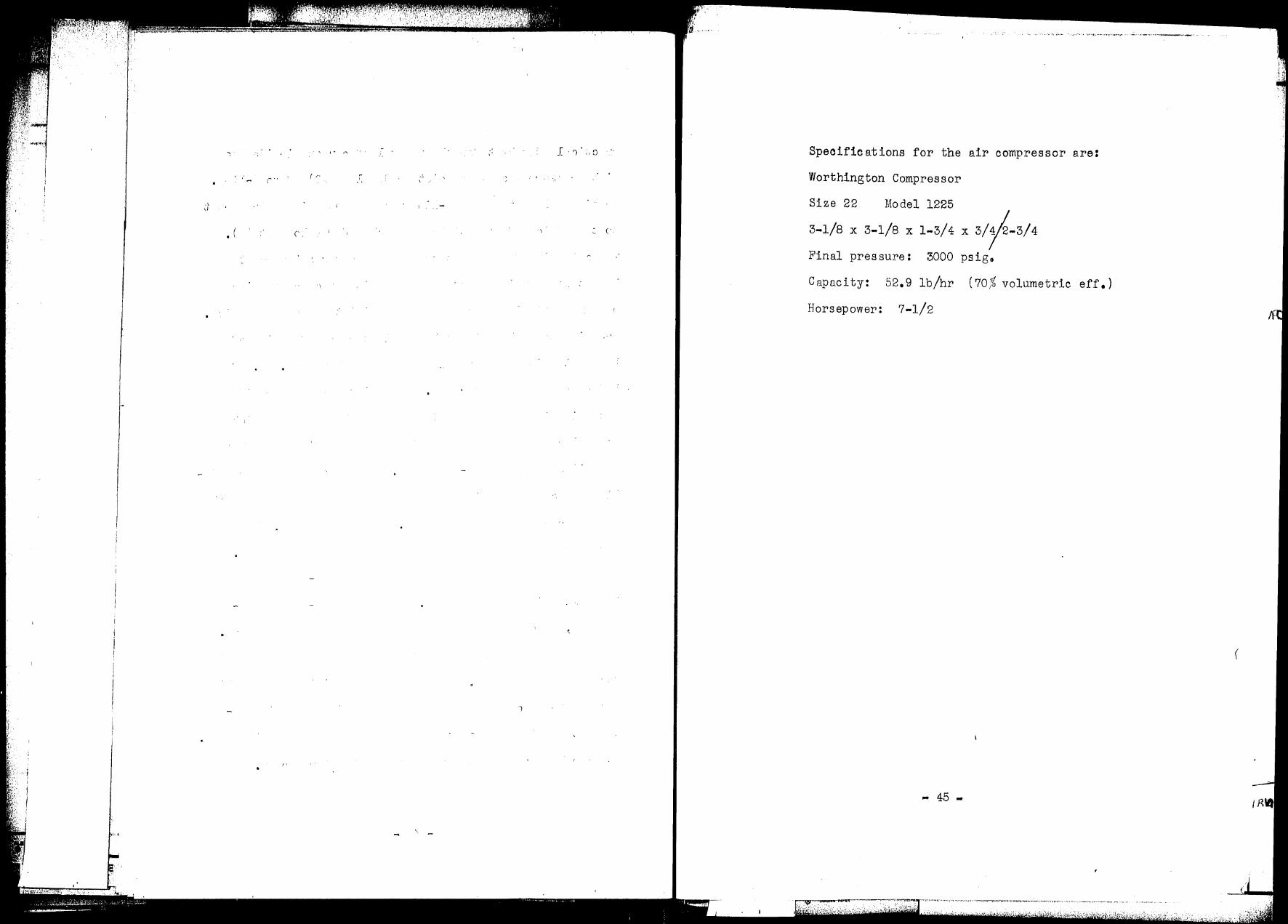
Specifications for the air compressor are:
Worthington Compressor
Size 22 Model 1225
3-1/8 X 3-1/8 X 1-3/4 X 3/~-3/4
Final pressure: 3000 psigo
Capacity: 52.9 lb/hr (70% volumetric eff.)
Horsepower: 7-1/2
... 45 -
Ii·
·1
\ \ \
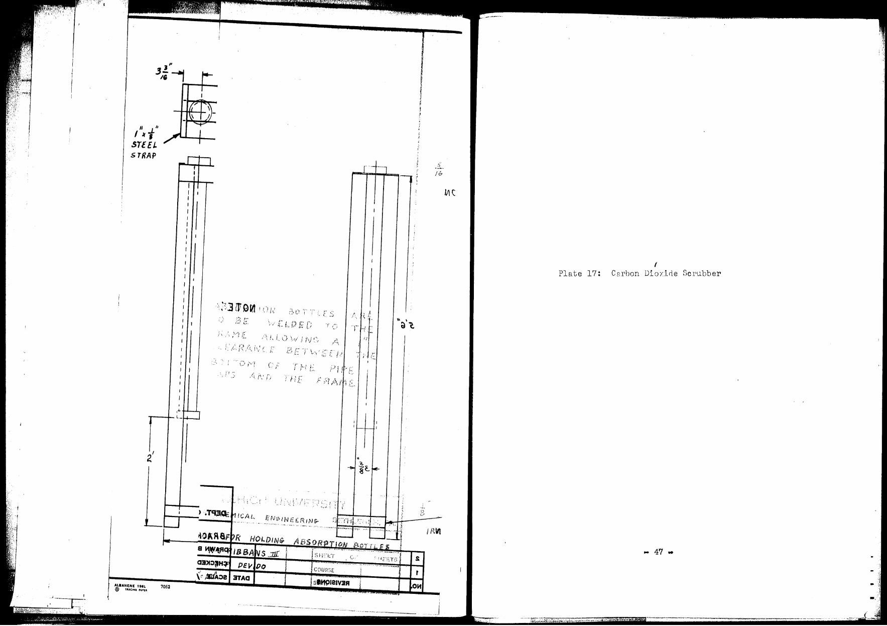
Plate 16: Bracket for ~oldi~g Adsorption Bottles
"46 M

iJ. ,.
\.
.. -.. ~r1·• .... , . . ·:: ...
• II II ' p p J 3,i -1 IOj-.-..-10 f---- IO'f t--3i,
II II
I "t STEEL STRAP
I
~
-
----+-----+-----+-----~--
,, I/ IJ ~
3X3><7i I I I I I I I I I
NfrL.E. IRON I I r-----_ A I I
I
I
~ I
I I I I
I I
I
I I
I I
I I
l I I I
I I I
I I l I
I I I
I 1
I I I I I I
I I I
I I I
I I
I I I
I I ~
I I
I I I I
I I I
I I I I I I I
I I I I I I I
I ,-'- ::J I. I I I I C - ... , L_ __,
I
~ .,
I I
~ L 2" A NGLE. IP.ON
I IJ NOTE: ABS OPT lON BOTTLES AR£ s, TO BE. WEI.DED TO THE. FAA/'1£ AL. LO \v I NG A (' CL.eARANCf BETvvEEN THE.
BOTTOM OF THE. PIP£ CAPS AND THE FRAM£
LEHIGH UNIVERSITY DEPT. OF CHEMICAi.. cN(i.lNE£1'1Nr BETHLEHEM, PA.
BRACI< ET FOR HOI.DIN~ ABSOR-.TION SoTrl.iS 2
DRAWN B'f RC RIBSANS .:11! SHEET OF SHEETS -t---+----------------+----+---COURSE t
!
C HECKE D BY J' P fJEVIDO NO, REVISIONS DATE SCALE 1'1=/0 11
SECT. , ......... -, .... '
--'·--~
,, .3.!~ ,, I
" /J
I "1 STEEL STRAP
2.'
ALUNENE IIIIL ® TltAGINQ l'A•U
---..--
)
7052
- \ ! ":, , .~
. , ,:~: G.
{ J'
- ......... ~.' ..... - ........ '-'· ._,,,.
I,
-rrr 1 s __ IJJ..
.. -·-· ----·· ·--·-··--·
/, ·, J .• ·,, < \ :··~
II
....... , ......... -... - ~,- .~---~._,~,.., __ _ r
slffl)l81V3fl OH ' . ··~
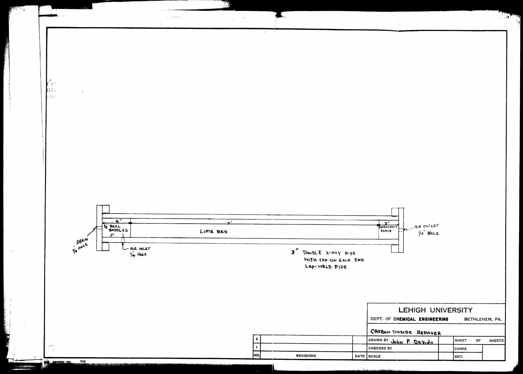
Plate 17: I
Di· ozj_rle Scrubber C9rbon
... 47 ..
:i - i!
i .·~
••. ·!
' 1 '.I 1 ·\
JI I ., . -. 1-J'· ,, \'..:,
~ ! j \ ;
,,·:".'~
'
. ,.
_____ ........ -----~.,..,..,......---,.,,,,.-._. ,,.,, ~·-·'"7"·, ..... -
I
I
L'' ='
/ - ~2 9ERL SIIDO\.ES L,me. BEt> 3'' I
Vi"'~ •': ,, ~o\. I LAIR IHL~T ·1~ 1/~ Hou. 3
2
1
NO.
I '3"
• t11Tll~1~ ,.,...,.,. ,__ ft,(~ ovTL'f=T ~ ., S~M.1i - Y4- Hole.
,, I Uau~L ~ x~ .. wy ~·?E. ~tT\.\ CAP ON E.~c.\o\ t,Nl)
LAp• Wt.\,.\) f) \ ~E
LEHIGH UNIVERSITY DEPT. OF CHEMICAL ENGINEERING BETHLEHEM, PA.
CRR-e,a~ u,~~•oe:. REM~ve.~ DRAWN BY Jo"N P. t:)1:, \hdo SHEET OF SHEETS
CHECKED BY COURSE
REVISIONS DATE SCALE SECT •
•, : 1 \ ,:
.,
.··. '
/ ...... . . :,
I , ·,
I . \
I/
I ~ .
s r k,
·-~
7052
...-~-------J _______________________ _ ,, ..__--&...... ____ , : II' .L
~,..-"'.-;'!'-.. "' ... ,A ... ,.-n...t·J'*'I".(~' -.. -, --· , .... L_,_..,.;..... ________________ _ 1 'a':,,.,qe I/ \ ·",
' .
\\ 3q,q yvH~x 3 J8voU E
allf3 HJF14 ,..,o qA, NT,V'I 39 I Cf GJ.!W •'lR..J
... ~ . ' :· '... ·~· -·~ t j J
' __ .(; i,
Ya ~3>1:::>JH:::>
3.JA:::>2 3TA SECT. 2 0121V3fl ,
f \
(_ __
\ ,,/ ./
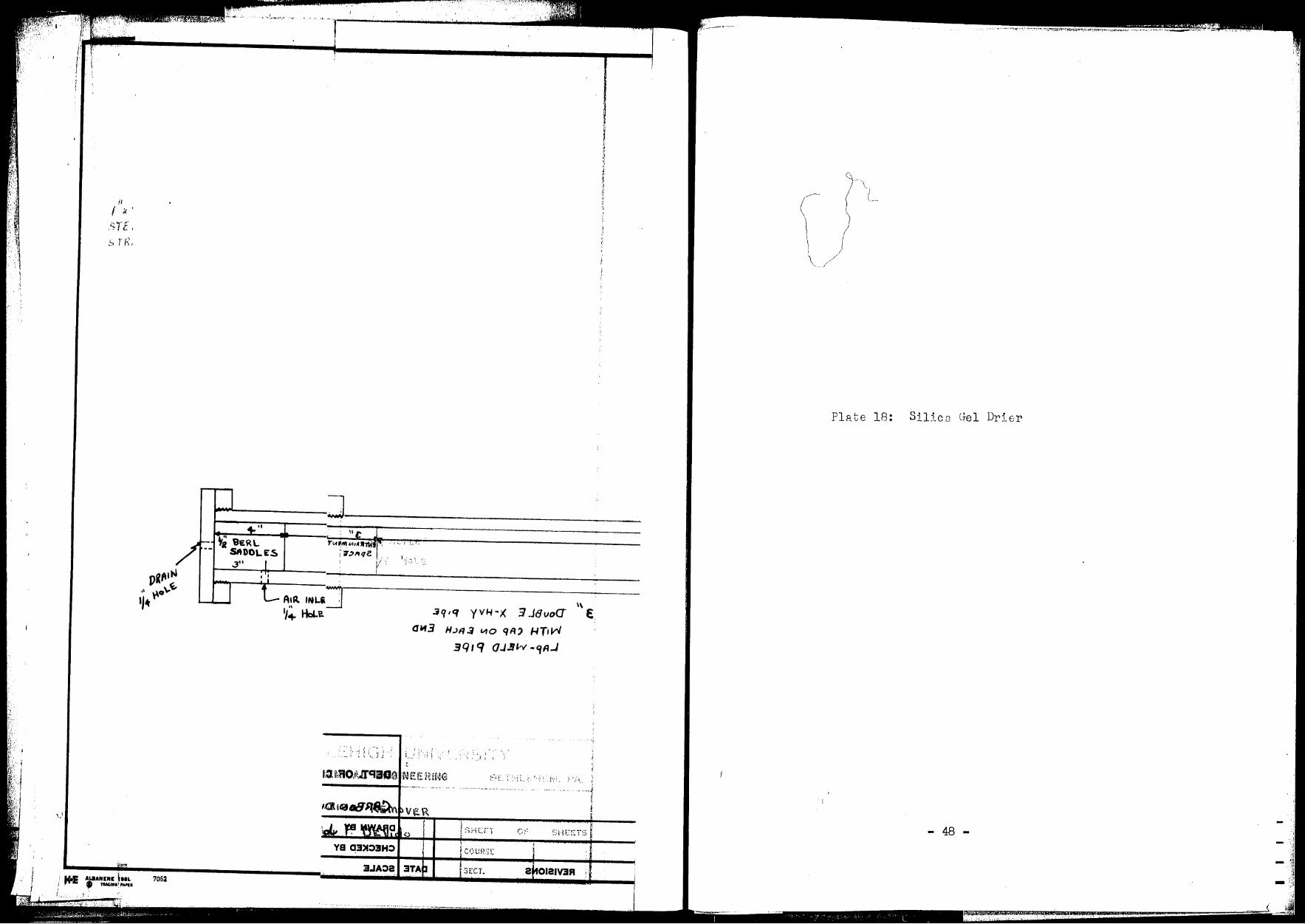
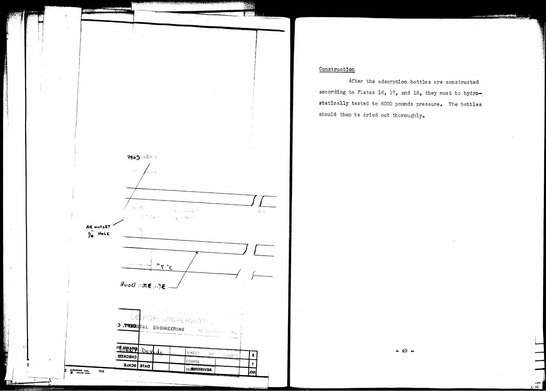
Plate 18: Silica Gel Drier
- 48 -
:¥ 4Z4. F~~+ a.
··, .) ··,1.
;j - ~a
J -i'._'.1

\ \
l i
' i
Sahe.A
Ai(( oul'-iT
~; t4olE
..
REVISIONS
31 7 ''
\
fl IR Jf\J t..E. r '/~ 1--toLE
LEHIGH UNIVERSITY DEPT. c,F CHEMICAL ENGINEERING BETHLEHEM, PA.
DRAWN BY Jo SHEET OF
CHECKED BY COURSE
DATE SCALE SECT •
.. ,.V, . , -~ ·'.,; ~ -.~-·:• ,,•,,,,,- :··.
. '·-:·:_ , .
R1(( oul ~£T /
,, ~+ ~o\.£
I ... ··---... ...J ,, t \ t..
;/ ,.·· ' , . .,.
. - ~ .. ,_ . . .. -.... ··- ~~--.
\; .... ' ... ,, . "'"•··· ........ ' ~ ,•• .
(iF •<-•.·-··-~.., ... .,., .•• ,,
COUl~SE 3.JA:>a 3TAa
ALIANENE fllL 7052
. .,, .... _ .. _,_. ···- ·-------~---------
C I
:.' .. \
.• ...... ~ .. , .. " '•" '
' ........ h ... ~ .. ,.,,
i r
·-r-.l_
Construction
After the adsorption bottles are constructed
according to Plates 16, 17, and 18, they must be hydro•.
statically tested to 6000 pounds pressure. The bottles
should then be dried out tboroughlyo
• 49 ll!f
.",'f ,.•,
·"
i
/. j '.! i D; .. ,./ ~f ·;
ACCESSORIES
In addition to the main pieces of equipment,
several items ere needed to aid in the operation and control
of the apparatus. These include valves, liquid level
gauges, thermocouple wells, pressure gauges, and orificeso
Several valves are required for the control of the
apparatuso Outside of the cold box, the valves on the
process streams noed only be rnterl at the operHting con
ditions. The valves inside the cold box will require
extensions on the valve sterns th.qt e xtm1d throut:h the
insul;1tion to the outside to en8ble the vr,J,res to be operated.
In order to prepare these valves for low temperature service,
the packing should be removed from the bonnet. If the pack
ing ls of the stranded F1Sbe~tos type it should be leached
with Bcetone to remove all lubric:::nts, graphited, ,md
replaced in the bonnet. If the packing is nob of this typo,
it should be replane~ with a braided &shestoR packing which
has been treated to remove all lubricants ::i.nd hydrocB.rbons.
In a similar manner, the VRlves them9elves should be cleAned
thoroughly to remove tmy lubricants nnd then given a l if~ht
coating of dry graphite on the threadso This ls done in
order to prevent the valves from freezing tight at their
low operating temperatures. The extensions on the valve
stems should be made from 1/4" diam. type 304 stainless steel
• 50 ...
:'1
·I . ; \
()
- - -· .. -., ... '~ ., ~ '~:' -, . :
rod because of its low thermal conductivity.
In order to completely control the distillation
column, a means of measuring the liquid level in the re
boiler and in the reflux trough was desired. The most
economical means of doing this was with manometers. Since
the pressure in the column will reach 125 psia. the manometer
glass should be thick enoLJ.gh to v;i ths tand this pres sureo The
front of the manometers should be covered with ~. 'Nire me sh
screen with holes no larger th,m a quarter inch. This is to
prevent flyin,3, cJ'ln "'S 0 (".-.....i in case of a manometer tube failureo
~ach :nanometer should be connected to the taps provided for
it on the re boiler ar1d on the reflux trough. In addition,
a manometer is to be connected to the upper tap at each
location in order to measure the pressure drop across the
column.
The trermocouple wells for the high _pressure line
con be made from short lengths of high pressure pipe. These
wells can be inserted into the high pressure line any place
a temperature is desired. The thermocouple wells for the
low pressure lines can be m~de by inserting a well directly
into the low pressure line. Tbe t:hermocouple recommended
for this apparc.tus is copper-constantan ( 1).
The pressure gauges needed for the apparatus should
be of the standard bourdon tube typeo Gauges will be needed
for the high pressure line, the column, the reflux condenser
"51 -
- ~: •..---:' . ·'
- . ' 1
'r r ,· lr .· "1 ... ) (' ~.
')
;
'·'
. r ,
1 ('
- li. -
?• •. -: . . •. ·:,~. '·
l ') r, 1
C
chest, and the liquefier with ranges of Oto 3000, 200 1 30,
and 30 pounds respectively. A gauge should be installed
in the high pressure line between the driers and the pre•
cooler and between the reboiler and the main expansion valve.
Orifices were designed to give a six inch deflection
in a manometer filled with Merri.am Oil with a specific
gravity of 0.827 when a flow rate of 1 lb-mol per hour of
air existed at -25°F. in a 3/8" type L copper water tubeo
The distillation column should be provided with
a safety valve set at 150 psiB• This must be done because
should any of the outlet lines hecOine plugged., it would be
possible to pump the column up to ~080 psig., which exceeds
its bursting pressureo The liquefier should be pro·;ided
with a safety vrlve set Bt W psir,. for the same r·eRson.
The pipes for these safety valves should extend out the top
of the cold box where the safety valves will be loc.:::itedo
- 52 •
:·.''.•, '., '.:,\ ..
, 1
[
[
r
:; ·1
Plate 19: 11 hermocouple Wells BJ1.d Orifice
'.
,.j , I
~ l
') 53 •
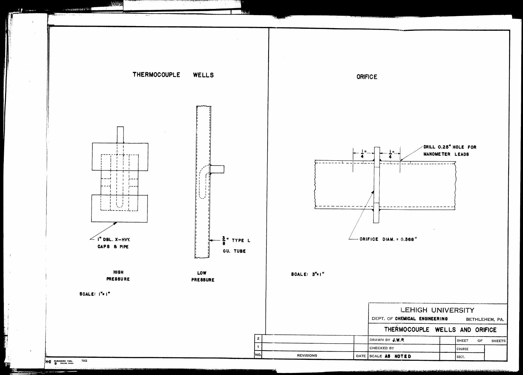
,: i
-,•;,· ·,1
• ' ... ~ ... ~ JJ• • ~~ • • - - ~
....... ------------------------------,~------------------·---------------,
THERMOCOUPLE
I I I I I
r---,- -4--+-,---• I I I I I I I I I I I I I I I I
I I I
I I __ J I
I I --, : I I
I
I I I r--1 I r--
1
: I I I I I I I
( I : I ',. ,, I L----L------L--
111 DBL. X-HVY.
CAPS a PIPE
HIGH PRESSURE
WELLS
~ I I I I I
_.J __
,, ! I ,' -·---: r I I
I I I I I ', ... _,
II - I
i.-- ! II TYPE L 8
OU. TUBE
LOW PRESSURE
ICAL E: 311• I 11
REVISIONS
ORIFICE
~ i I
DRILL 0.28" HOLE FOR MANOMETER LEADS
__ .__ __ 1 __ -·-------------·
I
--------------------
ORIFICE DIAM. = 0.368 11
LEHIGH UNIVERSITY DEPT. OF CHEMICAL ENGINEER ING BETHLEHEM, PA. ---·--------------------1
THERMOCOUPLE WELLS AND ORIFICE DRAWN BY J,W,P, SHEET OF SHEETS
CHECKED BY COURSE
DATE SCALE AS NOT ID SECT.

.. i I J
i
THEF
I I I I I
r---,- -~ -+-,---I I I I I 1 I I I I I I I I I I
I I I __ J
I r--
---1 1
I I I I
I I ( I I : I '•. •' I 1..---L------L--
l11 DBL. X-HVY. CAPS a PIPE
HIGH PRESSURE
30RIRO
---~ --r , -------
\ i c:.JAAIO 30PIIAO __ \
11 1 •"! :3 .JA08
~· ,)
I H18HlPPLr WC L LS 1t\ND GRIFH.':f:
l,
.w ,I, va HWARC '. r
YB 03)1::>3H::>
~if.CT. je1-101e1v:aR I
;
i l ! I
I
I
I
OPERATION OF THE UNIT
Before the refrigerator compressor is started,
the cooling water should be turned on to the condenser
and the superheater for about five minutes. During this
period, the compressor should be turned over by hand a few
times. This wi 11 prevent any liouid Freon slugs from
reaching the compressor. Then the refrigerator compressor
can be started and the expansion and the by-po.ss valves
adjusted to give the proper operatins conditions.
Initial start-up of the Worthington comoressor
is covered in their bulletin on three-stage angle compres
sors, type V4A3. Althou3h the compressor on hand is not
exactly this type, it is only a. modiftcation to allow 3000
psig. to be developed. Therefore, the operating instructions
should be used where applicableo
'J.1he valves on the rest of the c.p0ar8.tus should be
set so that the valves on the portion of the equipment to
be used are open. The rest of the valves should be shuto
The main expansion valve for the column should then be shut
slowly until the line pressure is built up to 3000 psigo
If the column is used, the secondary expansion valves on
the line from the bottoms to the reflux condenser and on
the overhead product should be slowly closed until the
column pressure is increased to operating pressure. This
- 54 -

I
_:.Jr: '. ;-,
t i_:,,, :·
n. r. r
• I
- .
. r r r- ,
may require a re-adjustment of the main expansion valve.
The two secondary expansion valves should be adjusted also
with the aid of the manometers so that the flow is cor
rectly proportioned between the overhead and bottoms.
Control of the column is accomplished by means of the by
pass lines on the reboiler and the reflux condenser. In
the same manner, if the liquefier is used, the vapor stream
from the liquefier to the two exchan~ers should be split
up with the aid of the manometers on Lhe warm-end vnpor
outlet lines.
Tr~e chemic al c le an-L:!) system is designed so that
switch-over from one ucit to 8nother can occur during
operation. After the pressure is relieved in the Bd3orption
bottle being changed, the charge can be removed by unscrew
ing tbe bottom cap and discharp;ing the contents into a
bucket •. , The soda-lime is to be discarded, while the silica
gel is to be regener2ted hy heating in G"l oven ::it 350 to
450°F. to a. constant weighto
- 55 ..
\
i i I
A.&.aANEIIIC ttiL;." ;., TIM.Htl PAl'Slf r,.,.
'[
('
... - {
..... --.·- .. -- ·.·····~···
COST ANALYSIS
The cost analysis is presented partly as an
itemized list and partly as a price for a group of items.
This is done because only those items are listed which
must be ordered. Other items which are obtainable in the
Chemic al Engineering Shop are not on the list but an esti
mate of their cost appears. It is intended that the
itemized lists serve as ~uides to ordering materialo The
sources named are in an effort to consolidate the ordering
to as few companies as possible 'but other sources can be
used. Where accurate cost dc,ta wn.s not ave.ilable, an
estimation of the cost was madeo These costs are indicated
as being estimatedo
- 56"
. ·,.·•,:. ,_ , ... ;.,.. : ·. . .. ~- .. ~, ..
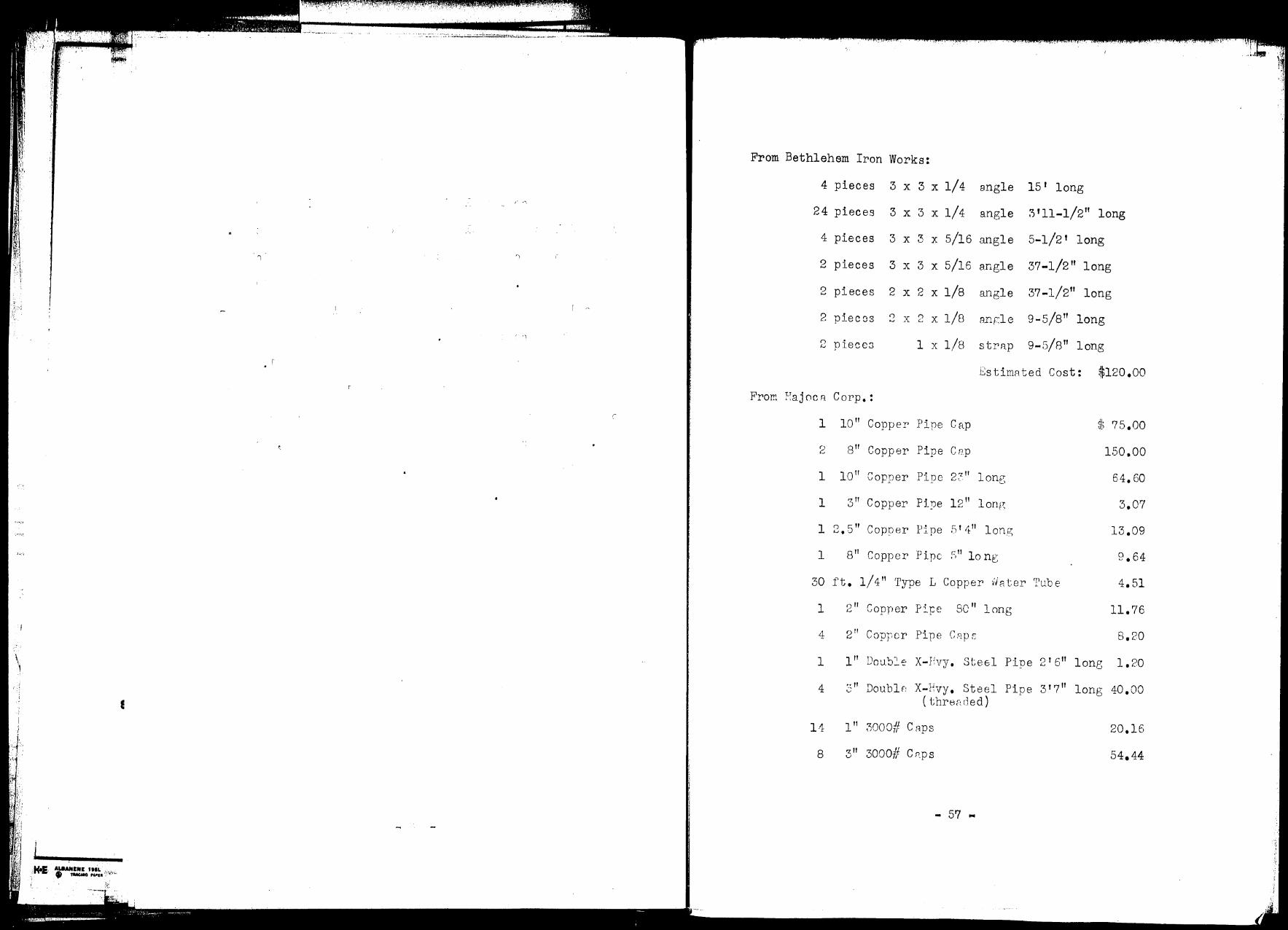
\ ·,
1
,. ---··· ···; .. _-.::...:;;;_.... ~~::~··-·- ----------
,- •"'\
From Bethlehem Iron Works:
4 pieces 3 x 3 x 1/4 angle 15 1 long
24 pieces 3 x 3 x 1/4 angle 3 111-1/2" long
4 pieces 3 x 3 x 5/16 angle 5-1/2' long
2 pieces 3 x 3 x 5/16 angle 37-1/2 11 long
2 pieces 2 x 2 x 1/8 angle 37-1/2" long
2 piec os 2 x 2 x 1/8 imrle 9-5/B" long
2 piece::; 1 x 1/8 strn.p 9-5/8" long
EstimRted Cost: $120.00
F u • C rom "aJ oc 11 orp. :
1 10'' Copper Pipe Cap
2 8 11 Copper Pipe C ep
1
1
loll ~ p. 2~ .. _.1, vopper ipe • long
3 11 C fj 12" 1 opper .pe ong
1 2, .s" Copner P:1-pe .Slit" long
1
30 ft. 1/ 4 11 Type 1 Copper ·ihi ter Tube
1 •) II r p' ,., vOpper :pe 80 11 1 ong
4 2 11 Copper Pipe C2p s
st 75.oo
1.so.00
64. 60
3.07
13.09
4.51
11.76
s.20
1 l" Dou.b2.::· X-J!vy. Stee,l Pipe 2 1 611 long 1. 20
4 3" Doublf: X-Evy. Steel Pipe 3 1 7 11 long 40.00 ( threr: ded)
11
8
l" 3000/1 C R.ps
3 11 3000# C!'.ps
20.16
54.44
- 57 ...

f/·:. I,· ,,,
I
,·r
,'/
r
I
·:·I . .-~z~(l
----- .. ~ .. · .. ,. -:--~· ·-·~-~-- --~---. __ .. __ .. _______ .._:___._,_., ...... _. ______ ,,_ .• , ... ______ ,.._ ·--·- ----~ -•-'. --
,·. r r
c- r \ I -
C
( \ -
, r
r _r \
\
L
\
l 1·
-
f' - I
\ .[
\ ~
i \
\ r
\ -
\
[
I
,-·
J
i
r J_
From Hajoca Corp.: (cont'd.)
1 12" Std, Pipe 2 1 long
2 12 11 Pipe Caps, Welding; Tube Turn
40 ft, 3/8 11 Copper Water Tube, Type L
1 Cylinder Freon-22, 22 lb, size ($12,00 returnable with cylinder)
1 Cylinder Freon-22, 9 lb, size ( ~iilO. 00 return able with cylinder)
1 6293 Fenry Expansj_on Valve
1 Drler V614C
2 Vibration Eliminator Plsxcnic or American
1 Gallon Ansul 150 Oil
2 No, 1451 Consolidated Relief Vnlve (1 set nt 30 psigo, 1 set At 150 psigo) for air
TOTAL
$ 9,58
31.36
12.46
51,72
34.58
B.25
21.90
43.12
It should be pointed out hen-: thRt ry lenvi:-1s out
the nitrogen cooler rmd storRce timk, the cost" would be
reduced by $159,G4 to a total of $514012. rr1hose prrr'ts are
the two 8" copper pipe caps end tr: e 8 11 copper pipeo
- 58 ...
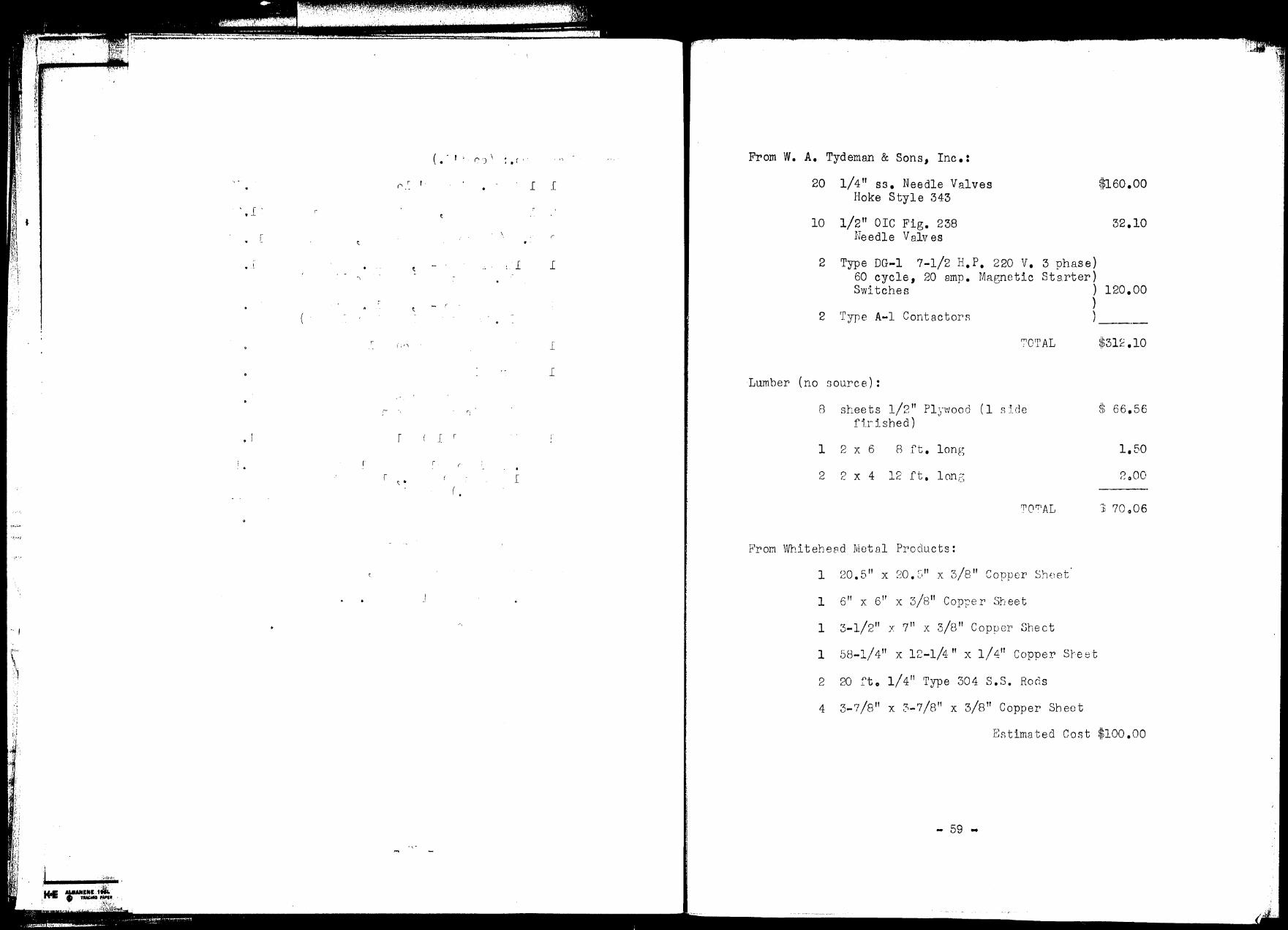
~. ' ·, ·"' ,•, - '., - -';~ .... ·. --:• ··. ( ,·, ' : . ',
l fl 'H ( • - I ' (') \ • r' .. '
~1 ·~·
0 -~ '. l l ; • ~ . , r . r
f . _,
' ~ [ \ r i'l lt·
. t . ' ~.1 .;,\:.I
l l ,.J. • . L ( ,;: J: -. .
', -,
~
(,'"\ l
.[
,- r·.
r r I ' • I
('
r ~ . I
( . , ..... :;.....
,. I
From w. A. Tydeman & Sons, Inc.:
20 1/4" ss • Needle Valves $160.00 Hoke Style 343
10 1/2 11 ore Fig. 238 32.10 Needle V a1v es
2 Type DG-1 7-1/2 H.P. 220 v. 3 phase) 60 cycle, 20 amp • Mngnetic Starter) Switches ) 120.00
) 2 Type A-1 ContactorR )
r;10TAL $312.10
Lumber (no source):
8 sheets 1/2 11 Pl ,·wood (1 s lcle cjh 66.56 J .. ~ f i.r i shed)
1 2 X 6 8 ft. long 1.50
2 2 X 4 12 ft. lon;: CJ 2o00
TO'T'AL ,.,,
70006 .D
From vVhitehe8d Metal Products:
1 20.5 11 x 20.C," x 3/8" Copper Sheet
1 6 11 x 6'' x 3/8" Copper Sheet
1 3-1/2" x 7" x 3/8" Copp er She ct
1 .SB-1/ 411 x 12-1/4" x 1/ 4" Copper Sre tit
2 20 fto 1/4" Type 304 S.S. Rods
4 3-7/8 11 x 3-7/8" x 3/8" Copper Sheet
Estimated Cost $100.00
- 59 •

'· . '
,:,,·.,.
, I
( [ .
(
0
. '
L
. .. ; 'I ,
('
• ('
') ( ,. .,
'l ,.
I
I I
r • :
r
''. ,. ~-
I
j
L
Maurice A. Knig~t:
3 0.25 fto 1/4" Ceramic berl saddles
BstimBted Cost~ 5.00
Monsanto Chemical Co.:
240 rt. 3 Santocel Estimated Cost $72.00
Conax Corp.:
B Cat. !Jo. PG-3 1/4" Gore
F'ittine;s from Lab and cost for ElE1ctr•ician
F'ro::i Copper Mill (Anacond,q):
300 rt. 1/ 4 11 x O. 049 Wn.11 r:opper Tubing
$39. 60
1•:stimn tect Cost :::.S6.00
'J'O'T.1 AL co~;T: ·:~ 120.00 cn:.56 312.10 ?0.06
100.00 5.00
?~~ aOO 09.GO 50.00 f)riaOO
:Jl, 498.52
• 60 ..
\ ·")
\ l J •
• u . ( ( (
') 0 -' ( ,.
( ( . (" [ . ' C'
r
. ( 1
\
APPENDIX
,I
.[
('
~-
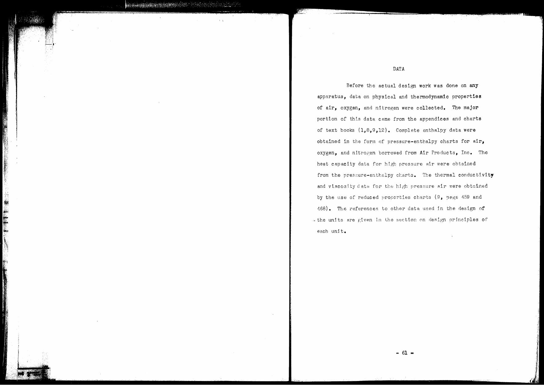
1·· ,
I I
~ ·,1,,·.1',;',,,, • •
DATA
Before the actual design work was done on any
appnratus, data on physical and thermodynamic properties
of air, oxygen, and nitrogen were collected. The major
portion of this data came from the appendices and charts
of text books (1,B,9,12). Complete enthalpy data were
obtained in the form of pressure-enthalpy charts for air,
oxygen, and nitro~en borrowed from Air Products, Inc. The
heat capacity dnta fo:r high pressure nir were obtained
from the presi:ure-enthslpy ctartn. The thermal conductivity
and vi :=ico s i. ty cl at H for thu high pres ~rnre Air were ob tnined
by the use of reduced properties charts ( 8, ;.>8ge 459 and
468). Tbe referenceR to other dat::i. used in the design of
-, the unlts Rre given in Lhe sectlon 0n de::d.gn Drh1ciples of
eri.ch unit.
- 61"

1 I i
('.
.. ., rJr,
')
')
r ')
' [
)
Figure 1
AH G jl I~
1
- c-,. ,. 'OI ~
-,_ F ~~ E
/ '\ '~
1 R
D
Ill-
1 z
c~ 0
B ( '
Scl"iemntic of Column and Heat Exchanger
- 62 •
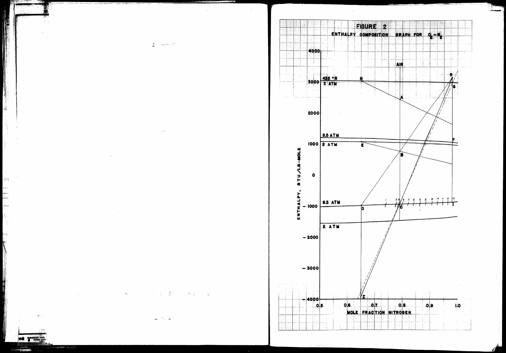
l , .. , ..
... a
' aa ~ :,
.f,:)j t-m
I'·' .. ,,,~ .. >-t"-i,.vi A, ..,
• ·n'..:~ -;,
% t-z l&I
T.~., I ·1
·, '1 '
L.
!
1-!0~0~~~+-~~~~~~~~~---4,.....,.~I-
L
2000-
8.&AlM F
1000 -2-AT!M
0
9 10 II 1a 13
8.5 ATM - 1000- D
A
2 ATM Ii
-2000
-aooo
0 8. 1- . :-~ota-i*-jl-----~----+--·- -
' I !
·1 ·;·· 1· -_ l ____ _
uo
.. ,..__·
- _____ J
~'i
t I.' I
.... ~ ........ --~·-·--···-· ...
I I
. ---·· ··- -- ,·~ • r .\
........ - ~ • -- --~---~ ~ ,4 •••• •
t , .. J' ... (" ,. ,.} .. ' .. ; .:·;
I
........ _ ....... _ .. __ :,~ -~ ,:·1 ... F· .. E:_ ... ! 1
.......... ~-· -· -----·--· ... ,., __ . - . - ....... - . -·~·· .. ··-- ..... ' ,'.·• : '~ i .~ :"_·) ~ .. .\ ; ' . ,
'_." ... ,1 :1•' ••
'
"i.t! ' {\ ,,·.
,.-...... .,
·-·· . -- ......
\ \ '
~~ I ·,' I
··········---···. ---·-···········-~·······"·-··' ...................... ,. •.••• , ..... ~~.',:·: ..................... _. ____ ._ .. ,_ ••• « .......... ..J1;,)01'• ...•
:.,j
' J ~-. ,,.
::•-::
SAMPLE CALCULATIONS
The first step was to determine the operating
pressure of the columno
Assuming the material from the reboiler is pure
oxygen and allowing a 15 psig. pressure drop in apparatus:
T = 175°R SAT.0 2,30 psia
0 Allowing a 10 F temperature difference,
T = 185°R SAT.N2,P=?
Therefore, the pressure of the colu.nm is 125 psia or B.5
atmospheres absolute.
The flow rates were then determi:ned for the various
streams by material and ener8y bal anccs o These balances
were in part performed with the use of Figure 2. The effect
of the heat leak, 3 BTU/lb., was included by raisins the
enthalpy of point A by 3 BTU/lb. or 87 BTU/# mol,
Fixing the top corcentroti on Bt the desired vs.lue
of o.98 mole fraction nitrogen, the bottoms composition was
varied until the column required a finite number of plat es o
This occurred when line RCZ had a slope greater than the
tie line through point c. In the calculations, all liquid
and vapor streams leaving the column were assumed to be
saturatedo
Assuming a bottoms concentration of 0.65 mole
fraction nitrogen, the following points are known on Figure
... 64 ..

'.:,:.·, :;;, t
. _r1.·
I ('
• I
.i: n.-'
,· r
. ,.\
.., -'· '
. [' _[r 1
_[ -C t. r
( -. t ' •
,,
1J r '
2; A, C, D, E, F, G, H, and I.
Figure 11
A=G+H+I
From an overall balance on
It is asswned in this and in all other balances
that A represents the product of the flow rate at point A
and the enthalpy of A, i.e. HAmA. The intersection of the
line from H through A and the line connecting points G and
I repreirnnts the addition point of strear.is G and I. Since
the flow rate of F' is equal to the flow nite of G, the
addition point of F nnd I cBn ~e locatedo
Writing a balance around the entire column,
B=E+F+I
'I'l::.e intersection of the line from E to the F + I
addition point with the air line locates point Bo
Wr~. tin:~ a balance 8.round the column from the
middle nf the rectifyiGB section down,
R=H+D
The intersGction of the line from D, througb B,
to the 0.98 mole fraction nitrogen line locRtes point R.
From a balance nround the middle of the column,
C = R + Z
The intersection of the line from R through C and
the 0 0 65 mole f:;:•r.;ction nitrogen line cJetermlnes z. The
next step is to determine the number of plates in the usual
- 65 ...
{+~- -· .... ······· .• - . ········-·· ........... , "" ----~·-···· .. ···-· .. , .................. _, ___ ·--··--··-···-··-··----·
::
I '
.l v
r
('
J
l
( . ' . : (' . . • •• ',• j
' ,)
. .
r C
,-.1
,..., >) l
·c
('
(· 'i
I I
)
., ("
. '
r, .. • --:- '1
(':
. . ~ . t . t '
~
t .'.
.[
rr •
manner. In Figure 2, only the traces of the plates with
the saturated liquid line are drawn in to avoid confusion.
Thirteen plates are required.
From Figure 2
ma.= 63.8 = 1.85 mr 34.5
mG = 1.85 m1
( Inverse lever arm rule)
mA = 52.9 #/hr= 1.822 # mols/hr
?roman overall m2terial balance and a nitrogen bRlance
1.s22 = m...r + 2.ssm1
1.822 x o.79 = 0.65mB + 2.85 x o.9BmI
~1 = o.516 - o.233~
1.s22 = ~ + 2.85(0.516 - o.233mH) = mH +1.470 - o.664mH
0.352 = o.336mH
o.352 = 1.048 # mols/hr = o.336
o.244 = o.272 # mols/hr
mG = lo85 X 0.272 = 0.503 # mols/hr
Reboiler duty (From Figure 2)
qr= mA(HB - He) = 1.822 (775 + 930) = 3100 BTU/hr
Reflux duty (From Figure 2)
q0
= 1~/HE ... HD) = 1.048 (1080 + 990) = 2170 BTU/hr
- 66 ..
I .r ;'· •.
• 'i r . r; r
I - • I -:-
.I=
.\ .\ 0
J
-!-
.f . )
r • J_
\
·\ ! -
I [ . I -- I - (
( '
- ·\ r I ,--- ( , ( ( ") • (' r --
.. - •),
•
• I
1 ('
Nitrogen cooler duty (From Figure 2)
qc = mI(HI + 1350) = o.272 (1350 - 920) = 118 BTU/hr
Calculation of heat
¢ = 0.027
transfer factor,~: ko.67cp0.33
µ0.47
for air: 200 atm. 500°R
k = Oe0217, k0 • 67 = 0.0768
cP = 0.325 1 Cpo. 33 = 0.688
µ = o.o5Bl, µ0
• 47 = 0.2625
¢ 0.027 X O .0768 X 0.688 = 0.2625 =
- 67 -
0.00543
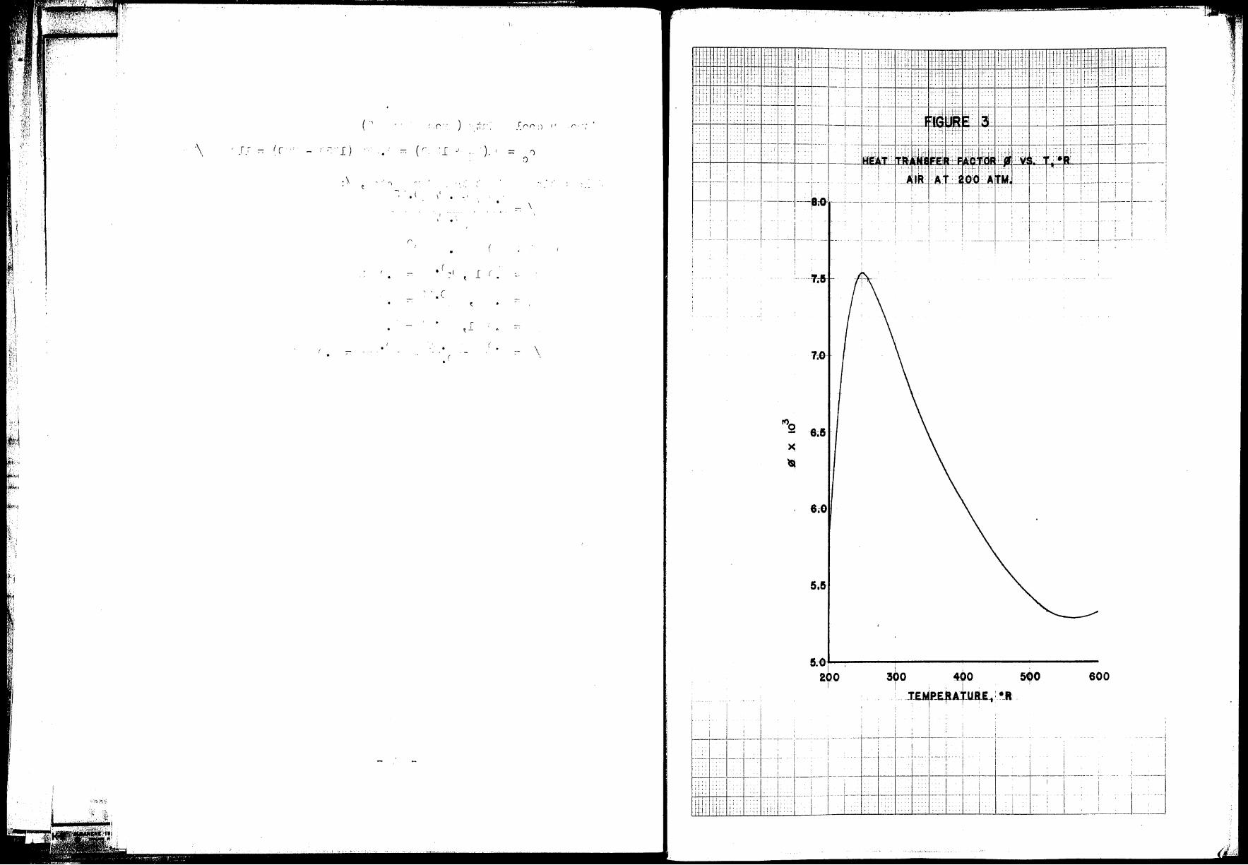
(' . .
.(' •. f.
\ rr ) ( ( J.~ ;, '.[ r· 'l ·' \ . :\
t 'i
• ( 1'
(' . • ( ~r :-
("
:- . '·
. • . :-( . '
\ .
-'· r' . Cr r :) ,,
) . ') :)
• \ ..
' I (
~ ..
r ~ J_ -·
- \
I' r'' ..
·-:T.&· -
7.8
6.8
!S.0·1 200
I
i ' 300 4,0
i , . I • . _tEMP.E.RAT_UR.E.,: •_R
5,0 600
i I . I : I .
-----1---l 1 ____ ' _ _;
1
'-- , ____ _, __ L __ ,__ J. ,__ _ _ __
I ; I I l ! ·--· -- --· · 1 ·- - I i I 1 ... - .•. : . i 1 ! I
- t--J+----~-_[ __ -_ ·;-·- !------ ' -ih-__...._-- -- ;- ----;---1----11
·-· ,·--; ' ------1 ~~L-....1.J...;..--.:..:..L---1.----'--__L~-..J-~--'----"'----'-'-'--~-'---1------L.--·_-·-1'-----_...__-_,_T___,_-_----"----'-.I ___ ! J_,_J
. 'i!f~~#~@irr,~~4*t#!til@h&;e%il.41f!i#fF.4WLF., £AJ,@f?:r:•~-t?-,i .. ..,, ··-'.
' I•' ',,._'· •~,• ,,_;,. •j
' \
I t {.:
i~ . ~-1. ; ;.
< \
,'·· ~! I.,
.. _. • .•~• I... .~
Reboiler design:
The rebeller is to consist of 1/4" x 0.049 wall
copper tubing wound in the bottom of the column.
For 1/4" tubing:
/ 0.25 TT 2/ outside lateral area ft= 12 = o.0655 ft ft
inside lateral area/ft= 0 •1f~'Ji = o.0398 rt2/rt CPoss sectional area for flow = 001522
77" = O 000126 rt2
4 X 144 •
Gt= 52 •9 4 19 X 105 #/hr.ft2
, G;08
= 3.14 X 10⁴
0.000126 = • -
D 0.152
t = 12 = 0.01267 D0
•2
= o.418 t 3.14x 10⁴ 4
Inside heat transfer coefficlent, ht' = 0041s xrf = 7.52x 10 ¢
T avg 310 + 210 260°R, ¢ == = = 2
ht = 7.48 X 10-3 X 7 o f)2
ho = 110 BTU/hr°F.ft 2
q = 3200 BTU/hr r
AT q
55.7 = 3200 = o.ol?4
X 10 4
7.48 X 10-3
= 562 BTU/hr°F.ft 2
1 l 0.01741 = 118 x 0.0655 + 562 x 0.0398 = 0.1~9 + o.045 = o.1s4
0.104 L = 000174
= 10058 ft. length of copper tubing to give
.required areao
on a 4" coil, L/turn = 4 xTf = 12.58"
on an 8 11 coil, L/turn = 8 x IT = 25.15"
If each coil has tr1 e same number of turns, n:
12.58n + 25.16n = 10.58 x 12 = 127
127 n = 37 •74 = 3.37 turns
- 69 ...
\ ( f_ -
I o
ll ' (' •
• r: l
( . --
-+' u . C I •
. \
. \ .
('
C I --
1
' r
. r
-'- . r
[ . \ [
r·
·-
l . '
[.
r - l
~ I .
: [i _; i: ' : 1. _- .. ;-, j ·. j
,-.., °' ... ' . 1. ''[, I ,., •
. ,:--:: ,· r
\ -
'j
\ _[ . r-. ..
= J ' • :- - ..L
., t
\ ("•
I t
t
• L
·\
r
I ·- l ;
J_
, . . ' -~ ( (
\ t .. c
• c l -- r I.
-- L ' .
Wind four turns :tn each of two concentric coils of 411 and
8" diameters with a pitch of one turn per inch.
Liquid nitrogen cooler:
q = 120 BTU/hr Overall U ~ 300 C
AT _ 180 - 175 5 7 2ow lm -
1 180-170 = 1n 10 = • J •
n 180-175 5 q 120 2
l·r d -0.0",i:;6 rt requ e areR = U~T = 300 x 7o2 - u,J
:81or 3/8" Type L copper water tube
A = 0.122s rt 2/rt m
(mean lateral area)
L - J • O 5 5 6 - 0 4. (~ 7- ft = 5 4 4 ' ' - 0 .1228 - 0 _,.Ju ' • 1ncnes length of 3/B" tube
to give ~equirea qren.
Reflux condenser:
For 1/4 11 Type L coprier wnter tube
2/ outside latcrPl araa = 0.0981 ft ft
in3ide lateral nren = 0.0725 ft 2/ft
log mean lnteral area= 0.0845 ft2/ft
Kcal / o ~t2 U = 770 = 105 RTU hr F.f ~c
q = 2200 B1'1J /hr 0
2200 0 l ft2 Area required= 105 x 10 = -•
Length of 1/ 411 tube 2.1
= O.OB 45 = 24,9 fto
Use 25 tubes, each one foot longo
- 70 -
, .. r ·-,._" ') . ; ·,')r-· ') r
~ . '.)' _. (. ,J.'
-\
::-'l r·l
r r
-f L
( . ( ( r.
l "
\
\ . \ -\
\ J
- \ -
r r - ::-
j
l. .. - -~
r·
• r ')
'I
')
r
. 1.-.,
rJ
Calculation of liquid rates in tower:
Above feed,
for 2.5 11 copper pipe
area for flow = 2.501
2TT 2 4 X 144 = 0.0342 ft
L/D 53.5
= -w- = 1.09 ( From Figure 2)
12 11 = 1.09 X 00503 X 28 = 15.38 #/hr
15.38 / 2 G2.5" = 0.0342 = 450 # hroft
Below feed,
f Oi'' 3" copper
a11 ea for flow
pipe 2
3.062 Tr = 4 X l44 = J.0513 rt 2
L3 11 = 47.6 + 15.4 = G3.0 #/hr
63 G-z" = = 1230 #/hr
u 0.0513
- 71 ..
= 47 oG #/hr
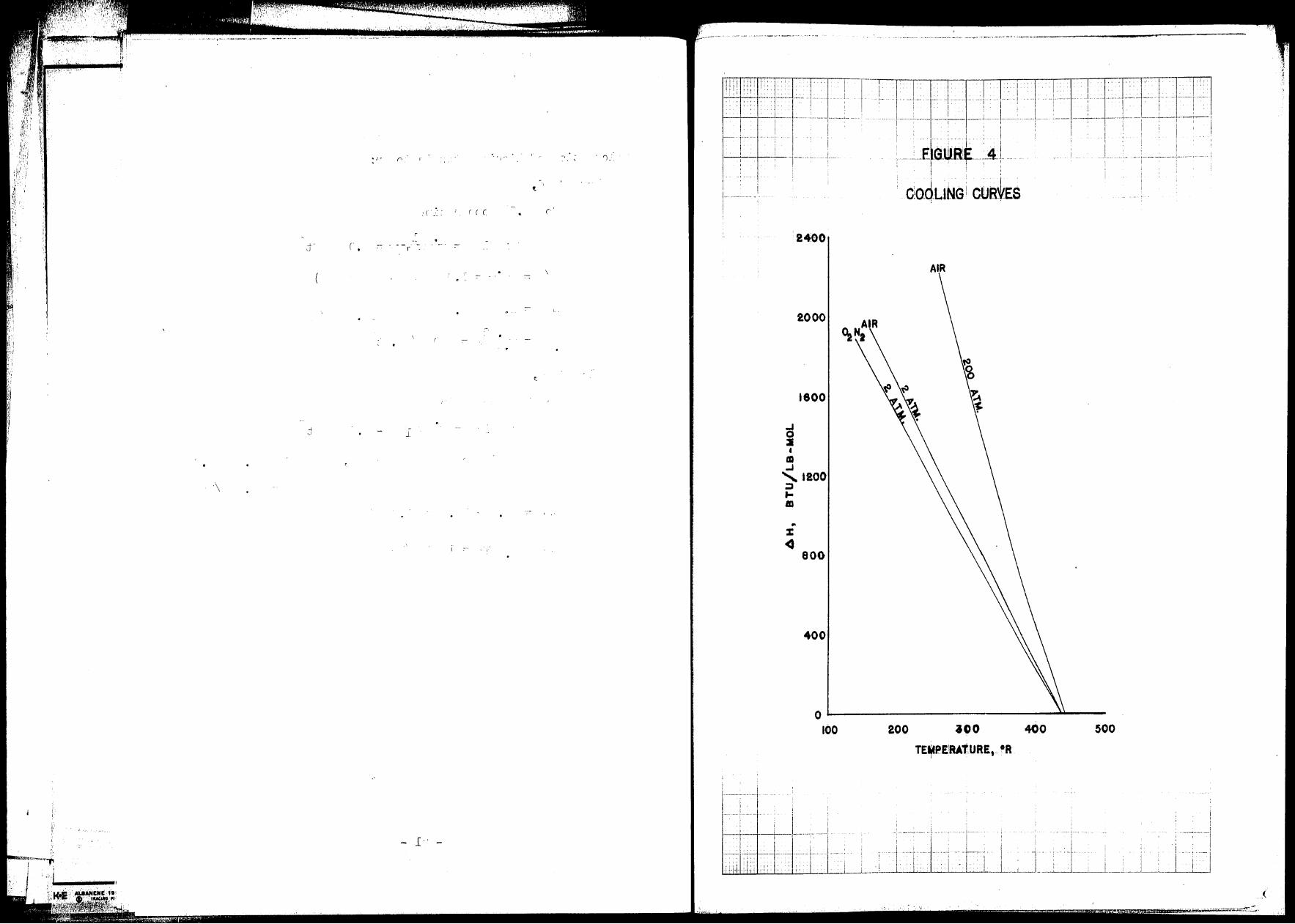
..... ('.
;( -'·. ( ( ( (
( • ..I.' d r .
I..
.:/ J.
\
l •' - -
··'.'··,1/
: ' i , _____ i __ --T I . ! I
•• ··-··--··- •• -- ··~-,-- ·--..-· --· .•..••. - -1 ..... , ~'.., '·
1 . P1l--Efl-r I 1 + ·: \ i rn ' . . . . t -f-1-+-~1··· ·-- ·1-'·· 1· C--!--'-T ~i
: . ] L. . -Efa~ Al L - i - I .
a 2 • ID
.J
2400
2000
1800
'1200 :, ... m
800
400
I I
I ' . , , i '
ctodL1NG i ctlJe~Es
o----------------------100 200 300
TEt,tP-E!RATURE, 0 R I
400 500
i I ! I ' !
~,1'--+--'1 :.i--+:,·:. _-)_-+ : :j_' ~1 l I F1 I ·_·· 11 : Ti , 1 TTJ1
U..:.~U..W.l.l-,.--!..-~_;_._J-....L--...J-j __ --' --'-'-'-----'--'-· --· .... _:__· -· . ..i..l -· • ..:..L..~' -- - ·-· I • _;___l_J____,_:___i.__....._
_(
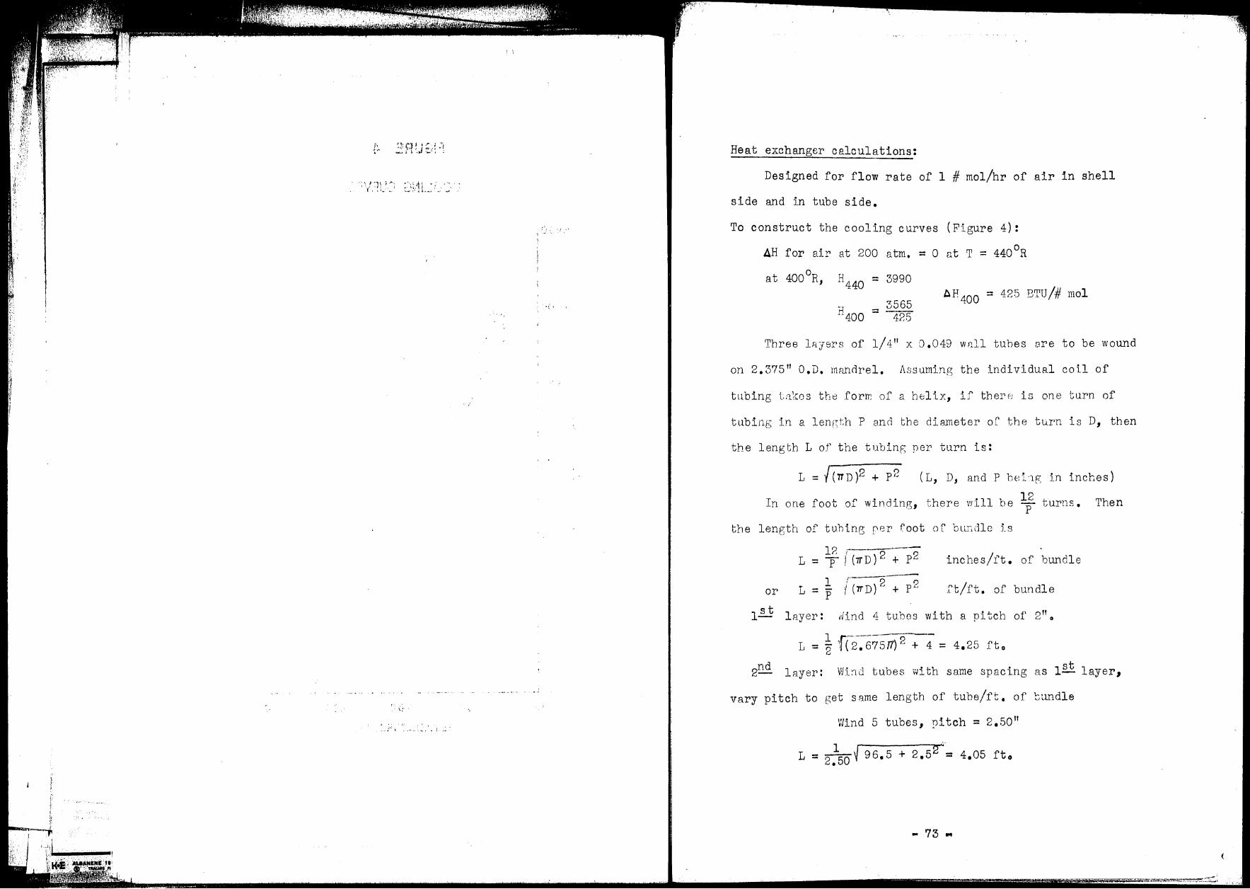
I
Heat exchanger calculations:
Designed for flow rate of 1 # mol/hr of air in shell
side and in tube side.
To construct the cooling curves (Figure 4):
AH for air at 200 atm. = 0 at T = 440°R
at 400°R, H440 = 3990
AH400 = 425 BTU/# mol 3565
H400 = 425
Three lR.yers of 1/ 4 11 x O .049 W8.ll tuhes are to be wound
on 2.375 11 O.D. mimdrel. J\ssuming the individual coil of
tllbing t:1kos the .forrr: of a helix, if theI'f: is one turn of
tu.bing in a length P and the diameter or the tu.rn is D, then
the length L of the tubing per turn is:
L = t ( TT D )2 + P 2 (L, D, and P bei~g in inches)
I f .f' • • h . 11 b 12 . n one oot OJ. winding, t ,ere V'il e p turns. Then
the length of tuhine; rer foot or bun.dlo is
l?. ;-----L = p/(11'D)2 + p2 inches/ft. of bundle
L 1
/("rrD)2 p2 tt/ft. of bundle or = p +
1~ 12.yer: Hind 4 tubes with a pitch of 2" 0
L = ! f(2-~67517) 2 + 4 = 4. 2 5 ft o
2nd layer: V1i:1d tubes with same spacing as 1st layer,
vary pitch to get same length of tuhe/ft. of tundle
Wind 5 tubes, pitch= 2.50 11
1 ··· L = 2•50 ~ 96.5 + 2.5 2 = 4.05 ft 0
• 73 ..
(
/.·,·
:t .. , w
;,, i ..
l
' . [
\
J
o•
r
" . '
\ .Cr J
. '
(
C' C
,. (
t
( .
. .-- - . ,. . .• -
'1 '
......... ,· {
:-
( '
('\
C\
. )
I ( -
I •
('
l
I
(',
( 1 (
, .
J:
,,
.'):'
After third layer was calculated, total number of tubes was 15.
o.n. of tube bundle= 3.875" = I.D. of shell
flow area of shell
area of mandrel
3.8752 tr = 4 = 11.80 in2
= 2.37527T = 4• 43 in2 flow area in empty
4 7 .37
annular space.
For a g8s flowing parallel to
tubes wound with a spacing equal
to their diameter, the fraction of
the total 2rea for flow is:
2D2
- 17D2
frrction for flow= ~~~~4-2D2
TT = 1 .. 8 = 0.607
Shell sid8 11ro P, for flow =
29 2 1" = = 97-4 # 1hr ft JS 0.03105 v 1 • ·-
7 • 37 X O • 607 144 = ·J.03105 rt 2
0 6 -0 4 0 5 D-Oo4 = 0.25-o.4
_ hS = 0.110 CpGs 0 D O G • = 60o2 ~ - 4.72
Cp = 0.24 BTU/#0 R
h3 = 0.110 X 60.2 x 4o72 X 0.24 = 7.50 BTU/hr°F.ft2
4. 8 X 10⁵
GT::: 15 =
h = 8065 X 103¢
T (inside tubes)
. 0 2 h = 7. 50 Brru /hr F. ft
Divide heat e1<:changer into steps of 400 BTlf 1 s on cooling
curve. Temperature differences are read from Figure 4.
1st step AH= 400 BTU/# mol, q = 400 BTU/hr 0
= 440 - 403 = 37 F,
- 74 -
Tt = 442 avg,
• ,-: I ~ . .. . ~ ',. ~ _,
,,,
r - _[
I
1- . (
( I
f
·\
(
('
r -·· /'\ -- ' ' (
r (' .J.C
[
-- -l:-.
Lr('
t. \
I I·
r. J
. . _( -~
_[
. r ( ' r
J
( l
..
= l
: ) \ ( _[ :-
l
(440-435) - (403-379) A Tlm = ln 440-435
403-379 = 12.1°F
r/ = 5.69 x 10³
, ht= 49.2 BTU/hr°F.ft2
AT -= q 12.1 l 400 = 0 ,0302 = UA
'Po find length of tube requJ_red for first step
0,03021 1 1
= 7.50 X 0.0655 + 49.2 X 000398 = 2. 549
2. 549 L = o.0302 = 84.5 feet for first section
1otal length of tube for all steps= 15004 fto
By multi plying the J ength of tu.bins ner foot of bundle
for e::i.ch laye1' by the nufr1,er· of tubes in thnt layer, the
total length of tubing ·:~1e::> foo~ of hLmdle can be found.
Length of tubing/foo 1-. of hnndle = 60,85 ft/ft
. 150.4 The length of t0A tube bundle 1s co. 85 x 12 = 29.65 inches
Incl1;.ding 8. srfety f::ictor of 1.25 fol" P-;RSes,
length of bundle = 29.65 x 1.25 = ~'57.l inches
To cnlculnte stell side pressure drop:
R = ~;2~ ~1~ 3~ 42 = 670, f = 0.097 (13, pase 140) e .::.,. x'-'. ()
fLG'-' 2gcDp2
2 0.097 X 37.1 X 4 X 934 X 12
= 12 x 2 x 32.2 x o.25 x o.18 x 3.62
x106
= 0. 334 #/ft2
Cold box size:
approximately 40% of column is 10 11 pipe, rest is 3
11 o.D.
0. 4 X 10 = 4
0.6 X 3 = 1.8
5.8" average diameter of column
- 75 ...
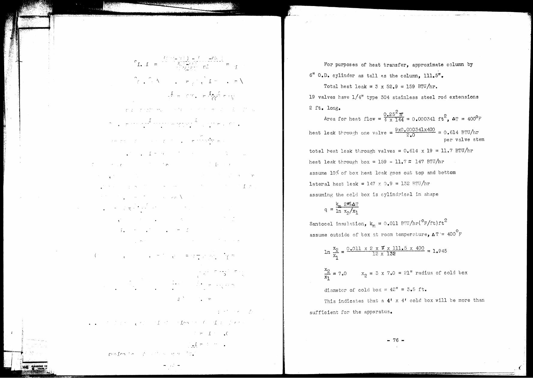
',,
ji• ~t . r
,, l··
('
l. l
I •
['I ·r,fr'I 'r
JA\i,'"
(
('
\
l
l
I ~ <
_[
,. ' ·-
. , u
\
) - (
.-
l
_[,~ '")
_r:'-
[''
l --
I. r =- ~
(( )
::-
I'
r· .l'
[
J
\
( l :
:- l .(
. . . [ :- •
' . - ·'' -
J
.. \
_[ _,
'·
( ..
For purposes of heat transfer, approximate column by
6" 0. D. cylinder as tall R.S the column, 111. 5".
Total heat leak= 3 x 52.9 = 159 BTU/hr.
19 valves have 1/ 411 type 304 stainless steel rod extensions
2 ft. long. 2 0.25 7T 2
Area for heat flow = ·1 x 144 = 0 .000341 ft , AT = 400°F
heat leak throu.ci;h one vBlve = 9x0. 00034lx400
2.0 = 0. 614 BTU/hr per valve st em
total beat leak through valves = 0.614 x 19 = llo7 BTU/hr
heat leA.k through box = 159 - 11.? ~ 147 BTU/hr
asswne 10;~ of box heA.t lc8k goes out top and bottom
lateral heat leak = 147 y: J.9 = 132 BTU/hr
asswnin?; the cold box is cylindricr,l in shape
lSu 21tLAT q = ln x2/x1
San toe el lnsu 1~,tion, ~ = O .011 BTU /hr( °F /ft) rt2
0 asswne outside of 'cox :1t room tomper2.ture, AT·= 400 F
X2 0.011 X 2 X ~ X 111.5 X 400 ln - = 12 X 132 = 1.945
xl
x2
= 3 x 7o0 = 21" radius of cold box
dio.metcr of cold bo;-: = 42" = 3.5 ft •
This indicBtes that a 4 1 x 4' cold box will be more than
sufficient for the app8ratus.
- 76 ..
(
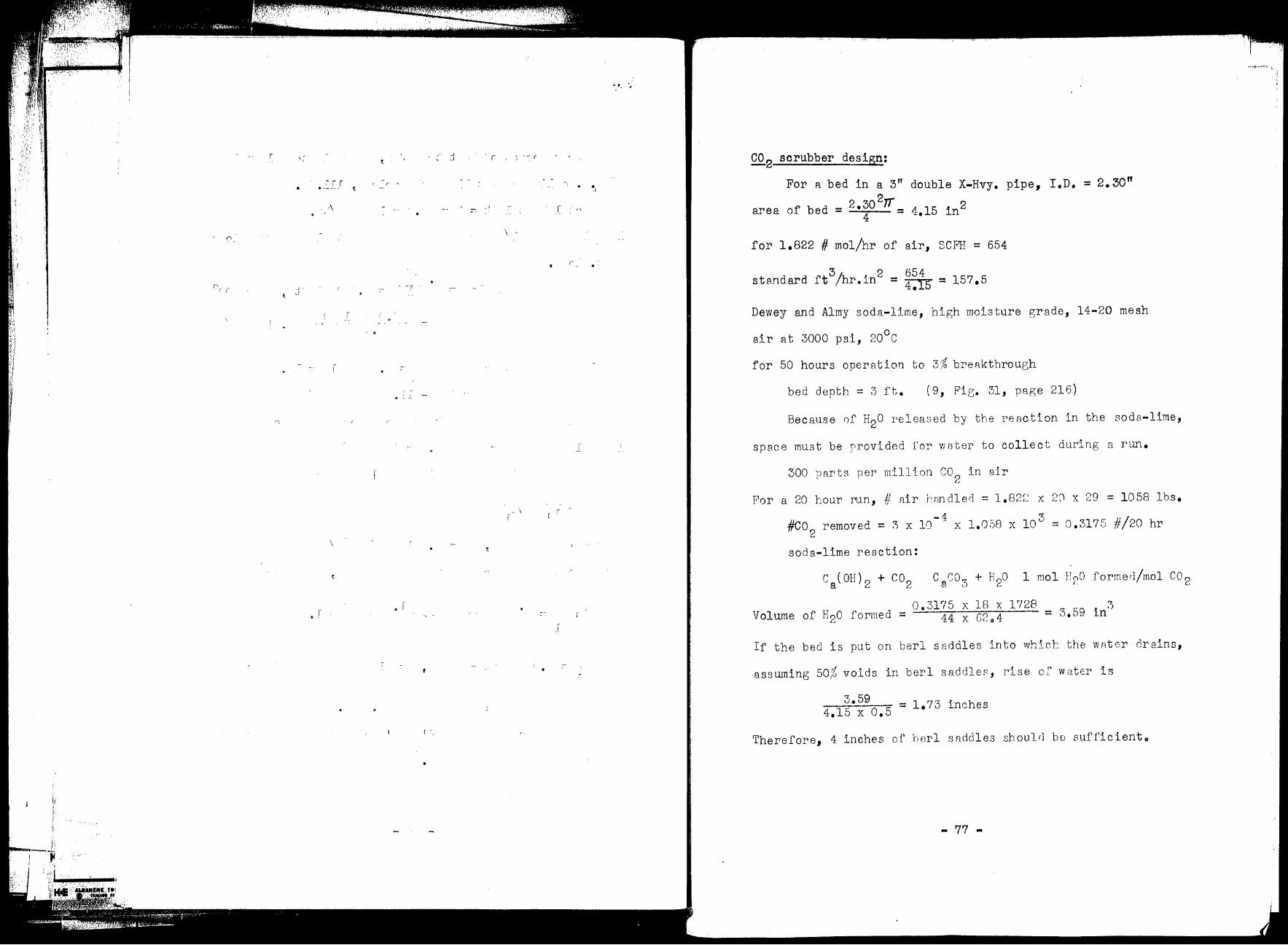
l;'. i j, ~
0
•
.. L·
l .J
.- r r . ·- -- -
I
r
\
I 0 '
·'
O - [ -
• r
l ',
) '~ (
\ .
\ I
,- ..
J:
' -
•
CO 2 scrubber design:
For a bed in a 3"
__ 2.30 2rr area of bed 4
=
double X-Hvy. pipe, I.D •
4.15 in2
for 1.822 # mol/hr of air, SCFH = 654
3/ 2 654 sts.ndard ft hr. in = 4•15 = 157. 5
= 2. 30"
Dewey and Almy soda-lime, high moisture grade, 14-20 mesh
air at 3000 psi, 20°c
for 50 hours operation to 3{ breakthrough
bed depth= 3 ft. (9, Fig. 31, page 216)
Because nf H20 released by the reaction in the soda-lime,
sp 8C e mu3 t be :-1rovi ded ror w ster to collect during a run.
300 parts per million C0 0 in air (;
For a 20 tour run, # air r,:::indled = 1.82;~ x 20 x 29 = 1058 lbs.
- 4 3 #CO2
removed= ?ix 10 x 1.058 x 10 = 0.3175 #/20 hr
soda-lime reaction:
Volume of H2o formed=
C ,./,0:z + H20 1 1 u O f 1/ 1 CO a· 0 mo 1,2 orme, mo 2
0.3175 X 18 X 1728 44 X G2o4
If the bed is put on berl saddles into whict the wAter drains,
ass wning 50% voids in ber 1 saddles, rise oF water is
3 • 59 = 1.73 inches 4.15 X 0.5
Therefore, 4 inches of rrnrl s11ddles should bo sufficiento
- 77 •

:r: .. ;. -··· ...
. r, ' \ . . ' ·"
!. . r - . ( '..
···-······-~-=-
\ r r r .. \
( .. ' = -: .. ..[.-_ --
.L
. I • r
·,
I
. - :-
t.
Drier design:
For a 3 foot bed in a 3" double X-hvy. pipe
2 area of bed= o.0288 ft
52.9 2 G = o.02ss = 1832 #/hr.ft
For 8-10 mesh silica gel, D = 0 .00634 p
µa.ir, 200 Rtm
DP G = 200.s, µ.
= o.058 #/ftohro
R O.Sl = 14.95 e
surface 8rea of gel/ft 0 of bed= a V
H = 1042 14 9h C) 0522 ~t ·do 407 X O ,J = • ... 0
p " " ~:- 29
= y lB X 200 = ..
322y"
y 1.82 wp 8 = = 0 .00565 w Ps =
322 cw, where c = o.00565p
8
PS l00°F 0 .9492 = 0 .OEA5 atm = 14.'7
1 1 = 19.15/ft " = Hao = 0 .0.122 ~~
1832 ')
G 30.55 Ji/ . ft-= 6() = ,. min._
Ge 30.55 X 0.00565 X 0.0645 b = pBHdo = Oo7 62.4 X 0.0522 = 0 .00488
X
at the end of 50 hours, bT = 0.00488 x 3000 = 14065
a Z = 19 .1.5 X
I y/y
0z 0.001( 2,1.,ig.216,p.1085) y0 = P5 MA_ 0.0645 18
PT MG - 200 x 29 = 0.0002
y = 0.001 X 0.0002 = 2 X 10-?
- 78 •
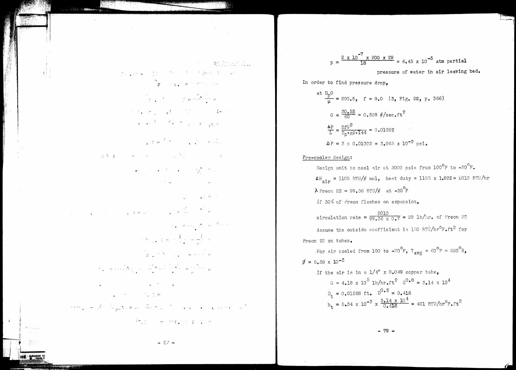
,'t I
,! ,i,
{ j, :j ','.
w r I
' I
,- ( r f
. '
\ .-J
. '
') :-
\
_j_
.J
. - - .. . - - .
. - (''
' ,- -
: r .. . -· .......... .
;f l. • . :-
r
i-
\ r (
i :- t •
\ -
., \ '.
. _'
:-
•
l
('
\
' (
('
• ct / . . \ u
i
-7 2 X 10 X 200 X 29 -5
p = 18 = 6.45 x 10 atm partial
pressure of water in air leaving bed •
In order to find pressure drop,
at DPG µ = 200.5, f = 9.0 (3, Fig. 22, p. 366)
G = 30.55
60
bp 2fG 2
= 0,509 #/sec.rt 2
L = -Dp_•_g_p-, l-4-4 = 0.01022
bP = 3 x 0.01022 = 3.065 X 10⁻² psio
Pre-cooler design:
Design unit to cool Rir at 3000 psiR fro~ l00°F to -20°F •
AH i = 1105 B1l1U/# mol, he Rt duty = 1105 x 1.822 = 2010 I3'FL1/hr a r
/\ Freon 22 = 99. 36 BTU/# 0
at -30 F
If 30°:S of r'reon flashes on expansio~,
2010 circulation rate= 99,36 x o.7 = 29 lb/·tr·. of }'reon ~:~
Assume the outside ~ocfficient ls 1:-iO RTiT/hr°F,ft2 for
Freon 22 on tubes.
For Air cooled from 100 to -?0°F,
If the 11ir is in n 1/ 411 X 0.049 copper' tube,
5 2 Go.s = 3.14 x 10⁴ r• = 4.18 X 10 lb/hr.ft u
D-1- = 0,01268 ft. D0° 2 = o. 418 V
3.14 X 10 4 ht 5.34 X 10⁻³ 401 BTU/hr°F.rt 2
= X 0.11s =
- 79 -
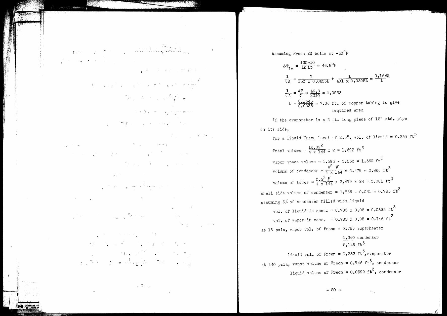
.L ,.
' • I
I J
\ _['
n
[ . l
')
( - ('
(~l O
r, .
I -
~ .
('
7. - . - - .
('
\
,.
- l
J
I 1 ..
'
Assuming Freon 22 boils at -30°F
130-10 l)Tlm = ln 13 = 46.8oF
1 l 1 UA = 150 x o 006551 + -40-1-x-=--o-.o-3_9_8.,...L =
o..1645 L
.1..... = ~ _ 46 • 8 _ U A q - 2010 - o.0233
L 0.1645 = 0
•0233
= 7.06 ft. of copper tubing to give
required area.
If the evaporator is a 2 ft. long piece of 12" std. pipe
on its side,
for a liauicl Freon level of 2.5", vol. of liauid = 0.233 ft3
rz
Total volwne 12.09 2
= 4 X 144 X 2 = 1. 593 rte.,
rz
vapor sp8.C8 volw11e = 1.593 - 0.233 = 1.360 ftv 82 1T 3
volill:1.c of coridenser = 4 x 144 x 2.479 = 0.866 ft
volume o:' tul;es o.52 Jr 3 = 4 x 144 X 2.479 X 24 = 0 0 081 ft
shell side volume of condenser 3
= o.866 - o.os1 = o.785 rt
assu..>ning 5/~ of condenser filled with liquid
vol. of liquid in cond. = 00785 x 0.05
vol. of vapor in condo = 0.785 x 0.95
3 = 0 .0392 .ft
= 0.746 ft3
at 15 psia, vapor vol. of f~eon = o.785 superheater
1.360 condenser
2.145 rt 3
3 liquid vol. of Freon= 0.233 ft ,evaporator
at 140 psia, vapor volume of Freon
liquid volume of Freon
- 80 -
= o.746 rt3, condenser
3 = 0.0392 ft, condenser
.. ,
..£· l .
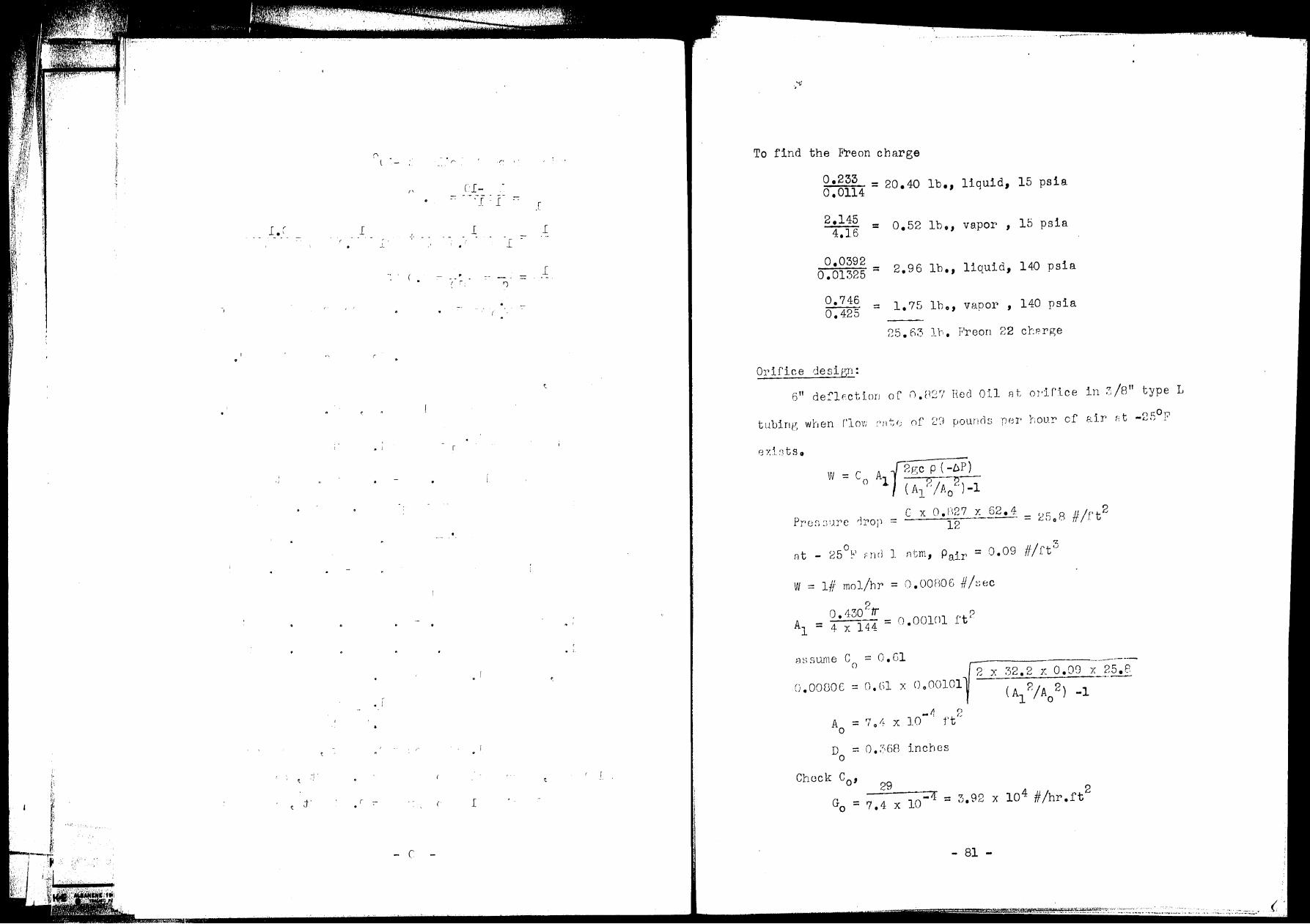
,''
'J I 1 \i I
--,
l. (
I •I
-..
_,. ·.'
('
,,
l ' - -.-
J_
(
' • I
. r
r ·-
- C
r· ('> I"
Cl--·-·--·--. '_[. l .. :
l l i
:--
.[ - = . ., i ...,
•,
. ' • i
( I
To f'ind the F'reon charge
o.233 0.0114
2.145 4.16
0.0392 0.01325
0.746 o. 425
Orifice desir;n:
= 20.40 lb., liquid, 15 psia
= o.52 lb., vapor, 15 psia
= 2. 96 lb.' liquid, 140 psia
= 1.75 lb.' vapor ' 140 psia
2s. fie, 1,-,. Freon 22 cr:rrge
6" dei'lFction of n.H2? Heel Oil 11t od.f'ice in 3/8" type L
tubin1r, when f'lov: cnt<; nf 2'J pounds per· ·hour cf .s.ir F.t -2f5°F
eY.istso
Pre;1 :,:Jre ,Jrop = C x O • H 2 7 Y. 6 2 • 4 #'- /f' t 2 ---------- = 25.8 12
( 5oi.., r . ; nt - 2, - r r10 1 ntm, ~
Pair= 0.09 #/ftu
W = 1//- mo1/hr = O.OOH06 #/~;~ic
0 .130 2
tr 0 A
1 = 4 x 144 = 0.00101 rt·
~1 ~, s urne ---------------------c = o.c1 0 2 x 32.2 x o.oa x 2s.2 --·--
o.ooeoc = o.cil x 0000101 ( Al'?/Ao 2) -1
-'1 r,
Ao = 70 11- X 10 ft(,
Do -· o.?,EiB j_nch es
29 G - -if
O - 7 .4 X 10
- 81 -
~~1::1i:~.~z:·~~ .. 3::~~!.~~:,·~:.·:_,~·,.,,·~., .. --,_ .. -····· ..... :.-· ___ ., .. ~ .. -____ .... / ... ,.:: .-.; .. :::::c.::.:;.• .\1
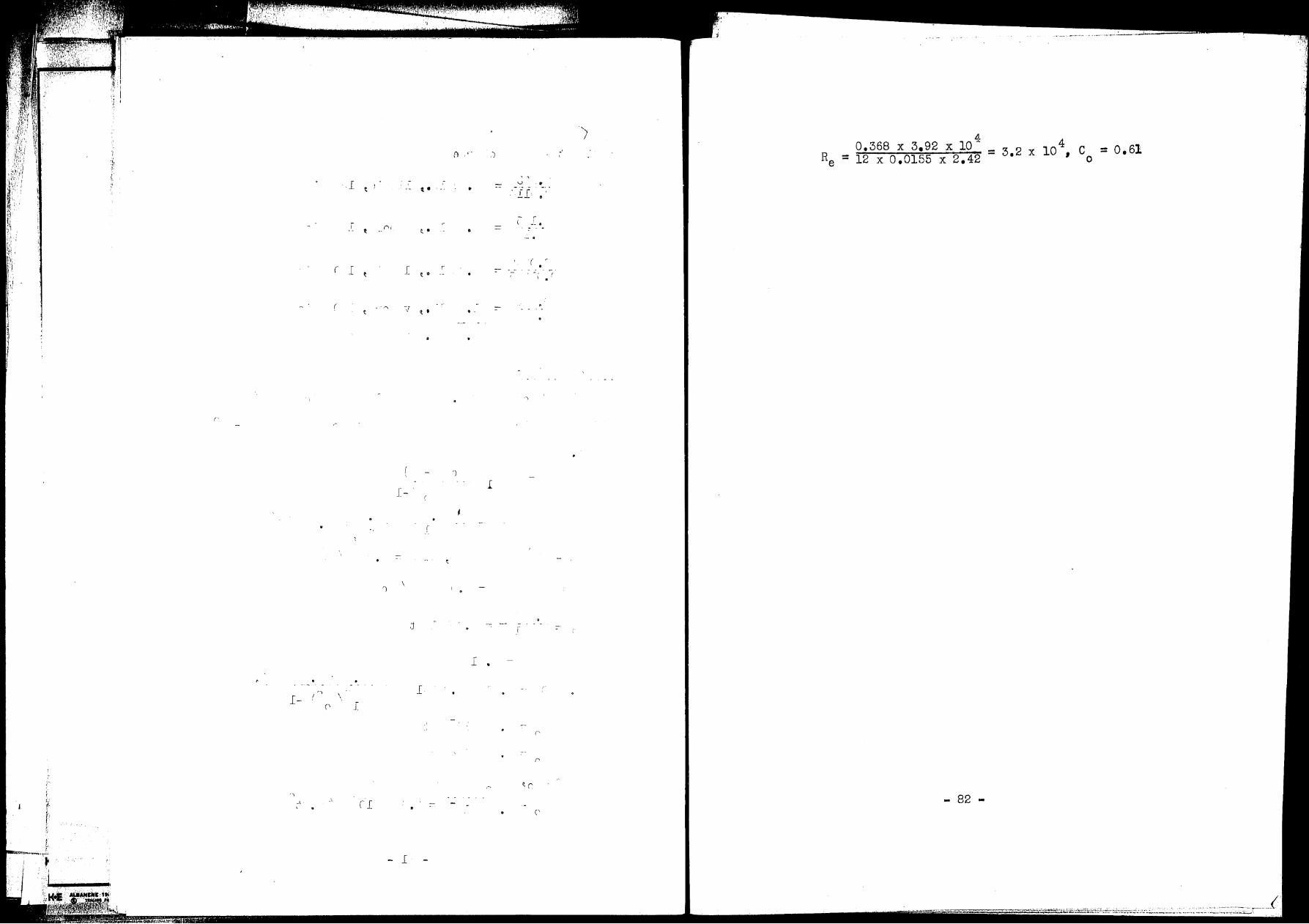
l ~
r ' "/
( l t l
( t ·:.r
r·
I-
\
j
',
I- \ (' J
·, .l
. \ ( _[ .
t ~, ..... ..__.;L ~ l
fl .)
q,. •
t • •
r ( 0 . _-
~ .
')
l
.r:
l
_[
,.. .
•
)
V ·•
_c •
(
1·
('
r,
~ ('
('
0.368 X 3.92 = 12 X 0.0155
.!1 X 10 :i:
X 2.42
82
= 3.2 X C 0
= o.61
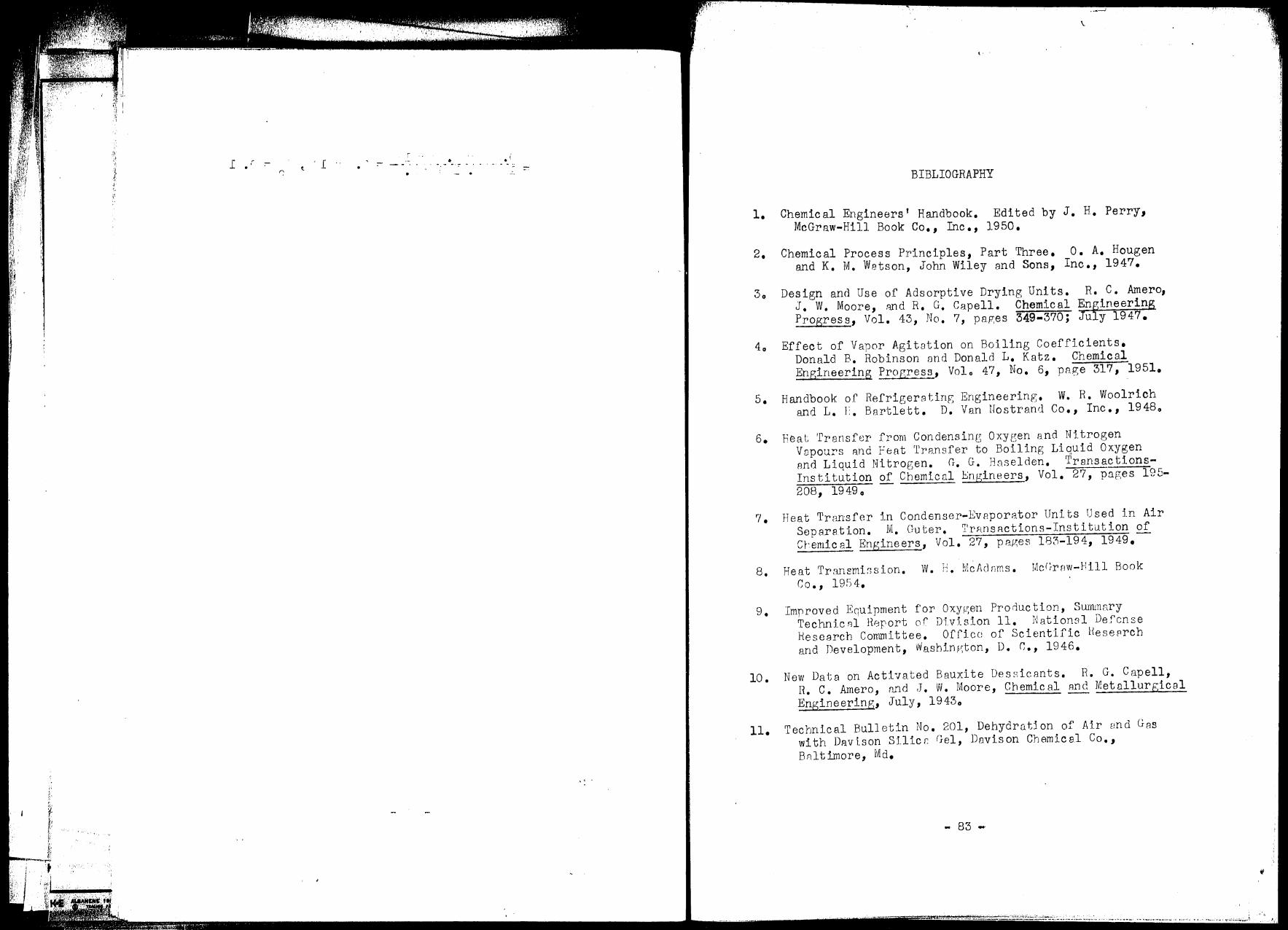
.. (
. :1 I
·.'·
·~· ,, {
!
tt , I r ..
• :- . - ·- -· - .. . -
•
,, .
\.
I· .
BIBLIOGRAPHY
1. Chemical Engineers' Handbook. Edited by J. H. Perry, McGraw-Hill Book Co., Inc., 1950.
2. Chemical Process Principles, Part Three. o. A. Hougen and K. M. Wetson, John Wiley and Sons, Inc., 1947.
3o Design and Use of Adsorptive Drying Units. R. C. Amero, J, W. Moore, :md R. G. Capell. Chemical En~ineering Progress, Vol. 43, No. 7, pap;es 349-370; Ju y 1947.
4o Effect of Vapor Agitotion on Boiling Coefficients. Donald B. Robinson nnd Donald L. Katz. Chemical Engineering Progress, Volo 47 1 No. 61 page 317, 1951.
5. Handbook of RefrigerRting Engineering. W. R. Woolrich and L. 1:. Bartlett. D. Van Hostrand Co., Inc., 19480
6. Heat ·rransfer· from Condensing Oxygen and Nitrogen V8pours R.nd Feat Transfer to Boiling Liquid Oxygen and Liquid Nitrogen. G. G. Haselden. TransactionsInstitution of Chemical Bngineers, Vol. 27, pnges 195-2081 19490
? • Heat Trrurnfer in Condenser-EvEJporator Uni ts Used 1.n Air Separation. M. Guter. TrRnsRctions-Institution of er~emical Engineers, Vol. 27, pR.ges 183-194, 1949.
8. Heat Transmi;;sion. W. H. Mcf1c1nms. Mc!~rnw-}lill Book Co., 19fi4.
9. Improved Equipment f'or Oxygen Prorluc tion, Summary TechnicRl H0r•ort of Dlvlsion 11. Nationsl Defense Hesearch Committee. Offlcc of Scientific Heseprch and Development, Vv'ashini:~ton, D. r,., 1946.
10. New Data on Activated Bauxite Dessicants. R. G. Capell, R. c. Amero, n.nd .J. W. Moore, Chemical 1md Metnllurgicel Engineering, July, 19430
11. Technical Bulletin No. 201, Dehydration of Air end Gas with Davison Silicc Gel, Davison Chemical Co., Bn.ltimore, Md.
- 83 ..
-~Ji/:" •• \~ ••.• ..! ~ .•. !::!~ . ..:..:~._::_'-''.J;.1;.i~i;.i::,.~.-;:· ,_;,,.,...,:,., .• · -- .. ·--· .•.•.• · ••... "'-···· ·-- •.• ·--.. - ............ ..
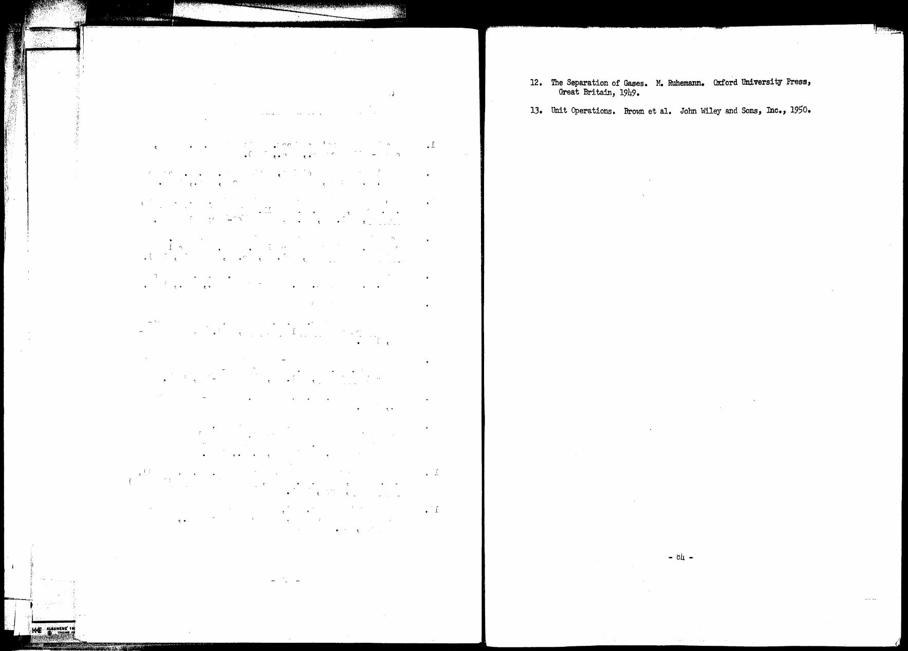
;Jr~ fF· {ii" ~~ '.
Ji ,i ,, ',\'
NI
('
• l
r_
'1
i i
. ( C • . i
'I \
,;
('
t
~ . C •
r
..
•
12. The Separation of Gases. M. Ruhemann. Oxford University Press, . J Great Britain, 1949 •
13. Unit Operations. Brown et al. John Wiley and Sons, Inc., 1950.
.l r
( . ')
t
~
r\
• ..
l
•
t •
_[
•
,!.