a hybrid simulation methodology for modeling dynamic recrystallization in uo2 lwr nuclear fuels
DESCRIPTION
2012 Journal of Nuclear Materials articleTRANSCRIPT

Author's personal copy
A hybrid simulation methodology for modeling dynamic recrystallization in UO2
LWR nuclear fuels q
Jonathan D. Madison a,⇑, Veena Tikare b, Elizabeth A. Holm a
a Computational Materials Science and Engineering, Sandia National Laboratories, PO Box 5800 MS-1411, Albuquerque, NM 87185, United Statesb Advanced Nuclear Fuel Cycle Technologies, Sandia National Laboratories, PO Box 5800 MS-0747, Albuquerque, NM 87185, United States
a r t i c l e i n f o
Article history:Available online 31 October 2011
a b s t r a c t
High burn-up, rim structures within uranium dioxide (UO2) light water reactor fuels exhibit markeddifferences in microstructure that are attributed to dynamic recrystallization. The recrystallization pro-cess has three distinct, interacting components: damage accumulation, nucleation and growth of dam-age-free regions, and subsequent evolution of recrystallized grains. In this paper, microstructural-scalesimulation techniques for all three processes are presented and assembled into a hybrid tool for modelingthe entire dynamic recrystallization process. The components of the model include a phenomenologicalmodel for damage accumulation and nucleation, a Cellular Automaton (CA) model for the growth andimpingement of recrystallized grains, and a kinetic Monte Carlo (kMC) Potts model for subsequent graingrowth. Preliminary results of the hybrid model demonstrate the evolution of a steady state grain size.Parametric simulations show the dependence of the steady state grain size on physical variables andon system size.
� 2011 Elsevier B.V. All rights reserved.
1. Introduction
Most LWR fuels are composed of UO2 with the vast majority ofthe Uranium being 238U with a small portion being enriched tohave 3–5% 235U. During reactor operation, 238U is known to capturea low energy thermal neutron, transmuting it to 239U. Subse-quently, 239U undergoes two beta decays to form 239Pu. This pro-cess enriches LWR fuels in situ to produce additional fissile fuel.A key characteristic of this reaction is the resonance neutrons thatform 239U are abundant at the outer surface of the fuel pellets, thusadditional enrichment of the fuel by in situ formation of 239Puoccurs preferentially in the fuel pellet rim as burn-up proceeds.This enrichment, in turn, leads to additional fission events occur-ring in the rim region of the fuel accompanied by marked differ-ences in microstructure and is commonly referred to as the ‘rimeffect’.
Blieberg et al. [1] and Matzke et al. [2] were among the first toreport a distinct microstructure at the rim. The development of ahigh burn-up structure has been found to occur when fuel pelletsexperience irradiation levels beyond 60–70 GWd/tU local
burn-up [3]. This burn-up structure is significant as it results inincreased yield [4,5]. The most striking feature of this region isthe tiny grain size that accompanies it. Usually these small-scalegrains are on the order of 0.2–0.3 lm in diameter when theyemerge, while the original grains are typically 10–15 lm in diam-eter. Another feature of this region, unlike the bulk of the fuel, isthat the fission gases are not contained in the fuel grains; ratherthey are present in relatively large 1–3 lm intergranular bubbles[21,23,24] with a different fission product composition and distri-bution than the bulk [6]. Other characteristics of the high burn-upregion include Xe depletion in the fuel grains, decreased hardness,and increased porosity.
While debate [3,7] exists regarding the mechanisms that governthe rim effect, the structure [3,8,9], composition [10,11] and prop-erties [5,12] of the resulting microstructures have been widelyexamined. Recrystallization is the most widely accepted explana-tion [3,5,9,11–16] for these features and is the premise upon whichthe approach reported here is developed.
Recrystallization is a process by which low free energy, damage-free material nucleates and grows to replace high free energy,damaged material. Thus, the driving force for recrystallization isthe free energy cost associated with the damage to the crystallinegrains, whether by dislocations, vacancies, or other irradiation-induced defects, and the rate of recrystallization increases withthe amount of damage. In typical metallurgical systems, plasticdeformation supplies damage in the form of dislocations. Duringrecrystallization, dislocation-free grains nucleate and consume
0022-3115/$ - see front matter � 2011 Elsevier B.V. All rights reserved.doi:10.1016/j.jnucmat.2011.10.023
q Sandia National Laboratories is a multi-program laboratory managed andoperated by Sandia Corporation, a wholly owned subsidiary of Lockheed MartinCorporation, for the US Department of Energy’s National Nuclear Security Admin-istration under contract DE-AC04-94AL85000.⇑ Corresponding author. Tel.: +1 505 284 4541; fax: +1 505 844 9781.
E-mail addresses: [email protected] (J.D. Madison), [email protected](V. Tikare), [email protected] (E.A. Holm).
Journal of Nuclear Materials 425 (2012) 173–180
Contents lists available at SciVerse ScienceDirect
Journal of Nuclear Materials
journal homepage: www.elsevier .com/ locate / jnucmat

Author's personal copy
the damaged matrix. The final structure is free of dislocations andtypically has properties (grain size, hardness, ductility) differentfrom the initial damaged system.
In nuclear fuels, the rim region is a prime candidate for recrys-tallization due to its enhanced damage accumulation, which arisesfrom two causes. First, with increased enrichment at high burn-up,it is estimated that fission events occur in the rim at a rate 2–3times that of the bulk leading to a higher rate of damage formation.Second, the temperature in this rim region is the lowest in the fuelwith a homologous temperature T/Tm � 0.2, where Tm is the melt-ing temperature. At this low temperature, the diffusive mecha-nisms available to heal damage occur very slowly; thus, damagecan accumulate to critical levels.
Since the damage accumulation and repair cycle in LWR andPWR fuels appears similar to the microstructural evolution seenin metallic systems undergoing dynamic recrystallization, theauthors suggest that simulations used to track such evolutionaryprocesses in metals can be adapted for use in nuclear fuel materi-als. While earlier recrystallization methods have focused primarilyon static recrystallization events [17–22], later efforts havebrought about hybrid models that have demonstrated the abilityto reliably capture dynamic recrystallization among a variety ofmaterial applications [23–25]. To our knowledge, such hybridmethodologies have yet to be applied in the investigation of micro-structural evolution in nuclear fuels. This paper serves as an initialadvance into such an effort.
2. Hybrid simulation methodology
The recrystallization process has three distinct, interactingcomponents: (1) Damage accumulation; (2) nucleation and growthof damage-free regions; and (3) subsequent evolution of recrystal-lized grains. In dynamic recrystallization, damage accumulation iscontinual, so that nucleation and growth of damage-free materialoccurs repeatedly. In this model, microstructural-scale simulationtools are developed for all three processes and assembled into ahybrid tool for modeling the entire dynamic recrystallizationprocess.
2.1. Hybrid model components
2.1.1. Damage accumulation and nucleationIn the current work, the rim region is modeled as a thin slice
(�50–200 lm) near the surface of the fuel pellet, with the assump-tion that rates of damage accumulation and dissipation by recrys-tallization are largely uniform over regions of this size. While thisassumption is not the most accurate globally, as damage accumu-lation decreases with increasing distance from the outer rim, theassumption of near homogenous energy accumulation and dissipa-tion over small regions of the high burn up structure are justifiedby experimental evidence [5,9,11,12]. For the purposes ofcomputation, the simulation space is meshed with N 2D-squareor 3D-cubic elements, each with its own crystal orientation andstored energy due to damage.
The model for damage accumulation and nucleation is phenom-enological. Every element begins with some initial stored energy atime zero. Fission damage accumulation is simulated by incremen-tally increasing the local stored energy over time. The functionalform for this incremental increase is given by
Xði; t þ DtÞ ¼ Xði; tÞ þ DXði; tÞ ð1Þ
where X(i, t) is the stored energy of element i at time t; DX(i, t) isthe incremental increase in stored energy; and X(i, t + Dt is thenew stored energy after time increment Dt. In these simulations,DX(i, t) is selected at random for each element and time such that
DX(i, t) e [0,DXmax], where DXmax is the maximum permittedstored energy increase in a given time increment. Note that sincethe stored energy values are used only in relative comparisons bythe cellular automaton model described below, they are dimension-less quantities.
The incremental increase in stored energy DX(i, t) is related tothe time- and position-dependent fission rate. Further, the totalenergy supplied to the system can be adjusted to match the localdensity of fission events in a real system by varying DXmax.
The physical mechanism for damage-free grain nucleation isdebated in the literature, but it is widely observed that the nucle-ation rate increases with the local stored energy [26]. Therefore, inthis model, a stored energy threshold Xt is selected, below whichnucleation cannot occur and above which it always does. Xt isdefined relative to the maximum allowed stored energy per site,Xmax, such that Xt = g Xmax, where 0 6 g 6 1.
At each timestep, nucleation events are attempted at a fractionof the elements in the system, g; hence, g scales the nucleationrate. For each nucleation attempt, if the stored energy X(i, t)exceeds the threshold energy Xt, then nucleation occurs at thatelement: the crystal orientation is set to a new value and the localstored energy is reset to zero. The nucleation threshold factor g andnucleation rate factor g are both user-defined constants.
2.1.2. Cellular automaton model for recrystallizationThe growth of the recrystallized nuclei is simulated by a Cellular
Automaton (CA) in which transformations are driven by a storedenergy value at each element [21,25,27]. CA models simulate theevolution of a system element-by-element using rules that deter-mine the status of each element based on the status of its neigh-boring elements [28,29]. While early CA models were applied tofluids and biology, cellular automata have recently been adaptedto understand microstructural evolution, particularly recrystalliza-tion [21,29–31].
For static recrystallization, the CA rule is simple: At eachtimestep, any unrecrystallized element that has at least one recrys-tallized neighbor element will recrystallize. In dynamic recrystalli-zation, the distinction between recrystallized and unrecrystallizedelements becomes blurred; at late times, all elements have recrys-tallized, often multiple times. Thus, to capture the details of dynamicrecrystallization, we modify this rule to an energetic criterion: Ateach timestep, an element with an unlike neighbor element willrecrystallize if it can decrease the system energy by doing so.
The CA recrystallization algorithm operates as follows: Eachelement is visited once per timestep. If the element i has one ormore neighbor elements that belong to a different grain, we ran-domly select one unlike neighbor element j. We then calculatethe energy for recrystallizing i such that;
DERXði; tÞ ¼ Xðj; tÞ �Xði; tÞ ð2Þ
where t is the current time, X(i, t) is the stored energy of element i,and X(j, t) is the stored energy of element j. Site i recrystallizes ifDERX(i, t) < 0.
The newly recrystallized element takes on the characteristics ofthe grain it is joining. Specifically, recrystallizing element i joins thegrain of its neighbor element j and assumes the same stored energyas j, so that X(i, t + Dt) = X(j, t). In static recrystallization, all recrys-tallized material is damage-free; therefore, immediately followingrecrystallization, element i has a stored energy X(i, t + Dt) = 0. Indynamic recrystallization, the newly recrystallized element i takesthe stored energy of its unlike neighbor element j, which may benon-zero.
Static recrystallization in a two-dimensional square lattice of ele-ments with site-saturated nucleation is shown in Fig. 1. The systemis initialized such that each element belongs to a unique grain; unre-crystallized elements have stored energy X(i, t) = 1; recrystallized
174 J.D. Madison et al. / Journal of Nuclear Materials 425 (2012) 173–180

Author's personal copy
elements have X(i, t) = 0; and stored energy does not change exceptvia recrystallization [DX(i, t) = 0 in Eq. (1)]. Fig. 1a illustrates theevolution of grain membership while Fig. 1b illustrates the evolutionof the stored energies. The nucleation and growth of low storedenergy, recrystallized grains in the initially fine-grained, high storedenergy matrix is evident in these structures.
During recrystallization, the fraction of recrystallized material fshould conform to Kolmogorov-Johnson–Mehl-Avrami (KJMA)model for phase transformations [26]. According to the KJMAmodel, for site saturated, static recrystallization, a plot oflog[�ln(1 � f)] vs. log(time) should produce a line of slope d, whered is the system dimensionality. Results from the CA recrystalliza-tion algorithm in both 2D and 3D agree with the KJMA model asshown in Fig. 2.
2.1.3. Kinetic Monte Carlo model for grain growthOnce grains have fully recrystallized and impinged, the primary
driving force for their subsequent evolution is the removal of grainboundary interface. This evolution regime is termed ‘curvature-driven grain growth’ because grain boundary motion proceedstoward each boundary’s center of curvature. The net effect is thatsome grains (typically the largest) grow at the expense of others(typically the smallest). The average grain size increases until allboundaries are eliminated and the final, equilibrium single crystalstate is achieved.
The kinetic Monte Carlo (kMC) Potts model has been success-fully employed in a variety of grain growth simulations, including
isotropic systems [32,33], texture evolution [34,35] and transfor-mation rate studies [36,37]. Just as in the CA model, each elementi, in the 2D or 3D mesh is assigned a grain membership qi. In a sys-tem with isotropic grain boundary energies, an element has oneunit of boundary energy for each interface it shares with an unlikeneighbor element. Mathematically, the total boundary energyassociated with site i, E(i), is given by
EðiÞ ¼Xn
j¼1
1� dðqi; qjÞ� �
ð3Þ
where d represents the Kronecker delta function such thatd(qi = qj) = 1 and d(qi – qj) = 0 and n is the number of neighbor ele-ments j.
The kMC Potts algorithm then proceeds as follows: An element i(with grain membership qi) and one of its neighbor elements j(with grain membership qj) are selected at random. The energychange DE(i, j) for switching the grain membership of element ito qj is calculated using Eq. (3). The switch is then performed withprobability
Pði; jÞ ¼1 if DEði; jÞ 6 0
exp � DEði;jÞKBTS
h iif DEði; jÞ > 0
(ð4Þ
where kB is the Boltzmann constant and Ts is the simulation temper-ature. After N switch attempts, the simulation time is incrementedby 1 Monte Carlo Step (MCS).
Fig. 1. Evolution of (a) grain structure at 10, 20, 30, 40, 50 and 60 timesteps and (b) stored energy distribution during static recrystallization at 10, 20, 30, 40 and 50 timestepswith scale bar indicating binary energy field. In (a), color indicates grain membership; in (b) color indicates stored energy level where blue is X(i, t) = 0 and red is X(i, t) = 1.(For interpretation of the references to color in this figure legend, the reader is referred to the web version of this article.)
(a) (b)
0.1 1 10 100
y = 0.0012x2.1
R= 0.99
-ln (
1-f )
Simulation Time (MCS)0.1 1 10
y = 0.024x2.8
R= 0.95
Simulation Time (MCS)
0.0001
0.001
0.01
0.1
1
10
0.001
0.01
0.1
1
10
-ln (
1-f )
Fig. 2. KJMA plots for (a) 2D and (b) 3D site-saturated, static recrystallization indicate agreement with the KJMA model.
J.D. Madison et al. / Journal of Nuclear Materials 425 (2012) 173–180 175

Author's personal copy
Results of a kMC Potts model grain growth simulation in a 2Dmicrostructure with initially random grain membership is shownin Fig. 3. An increase in the average grain size with time is apparentin the microstructures in Fig. 3a–d. Grain growth theory suggeststhat the average grain size should increase parabolically with time[34,36,38]; Fig. 3e indicates that the kMC Potts results agree withthat scaling.
2.2. Hybrid model for dynamic recrystallization
The complete process for dynamic recrystallization in the rimregion is simulated by coupling the three elements presented inthe previous sections: (1) Continuous energy accumulation andrepeated nucleation events, (2) CA recrystallization and (3) kMCPotts grain growth. The coupling is accomplished by initializingthe system and combining each component model at different pro-portions. For example, consider a system with a nucleation thresh-old factor g = 0.95, nucleation rate factor g = 0.20, andrecrystallization rate r = 100. In this case, each timestep wouldconsist of the following three processes:
1. Increment every element’s stored energy by DX, then attemptnucleation at 20% of the elements in the system (i.e. 0.20N ele-ments). The nucleation attempt is successful at any elementwhere X(i, t) P 0.95Xmax.
2. Perform 100 recrystallization events per element (i.e. 100 CAtimesteps).
3. Perform one grain growth event per element (i.e. 1 MCS).
By varying the system parameters g, g and r, different nucle-ation rates, nucleation success frequencies, and recrystallizationto grain growth ratios can be investigated. Note that in this formu-lation, the boundary mobility is assumed the same for both recrys-tallization and grain growth processes.
The hybrid model was programmed as a user application withinthe SPPARKS open-source stochastic parallel particle kinetic simu-lator platform [39]. Combination hybrid models of this type havebeen presented elsewhere [21,23,27] and have primarily beendeveloped for descriptions of static recrystallization [18–20]. Themethod developed here extends this approach to dynamicrecrystallization.
2.3. Effects of simulation parameters on system energy and grain size
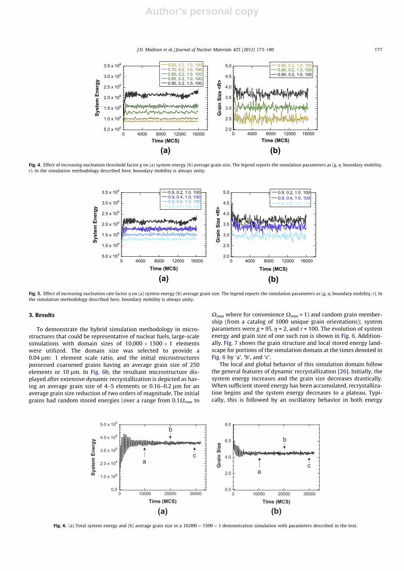
For the simulation of dynamic recrystallization, the nucleationrate factor g and nucleation threshold factor g are particularlyimportant. Combined, these factors determine the average grainsize and nominal system energy over time. Figs. 4 and 5 illustratethe effects of changing the nucleation rate and threshold factors.The initial microstructures in these cases are comprised of singleelement grains possessing random stored energies (over a rangefrom 0.1Xmax to Xmax where for convenience Xmax = 1) and randomgrain membership (from a catalog of 1000 unique grain orienta-tions). The system energies plotted in Figs. 4a and 5a are thesum of the stored energy over all elements in the system, i.e.Energy ¼
PNXði; tÞ. In Figs. 4b and 5b the grain size is the simply
the average grain radius of all the grains in the system.As seen in Figs. 4 and 5, increasing the nucleation threshold fac-
tor results in higher system energy and larger average grain sizewhile increasing the nucleation rate factor results in lower systemenergies and smaller average grain size. As the nucleation thresh-old factor increases, fewer nuclei are continuously introduced,thereby eliminating many opportunities for reductions in systemenergy by recrystallization and allowing those nuclei that areintroduced to grow larger in size. As nucleation rate increases,more nuclei are introduced, which decrease system energy andproduces a smaller average grain size.
(a) (b) (c) (d)
(e)
0 50 100 150 200 250 300 350
Simulation
k*t1/2 + 1, k = 8
Gra
in S
ize
< R
>
Simulation Time (MCS)
0
10
20
30
40
50
60
Fig. 3. kMC Potts grain growth simulation for an initially random system. Microstructures show grain coarsening behavior at (a) 0 MCS, (b) 10 MCS, (c) 50 MCS, and (d) 300MCS. (e) The average grain size increases parabolically with time as predicted by grain growth theory (solid line).
176 J.D. Madison et al. / Journal of Nuclear Materials 425 (2012) 173–180
Author's personal copy
3. Results
To demonstrate the hybrid simulation methodology in micro-structures that could be representative of nuclear fuels, large-scalesimulations with domain sizes of 10,000 � 1500 � 1 elementswere utilized. The domain size was selected to provide a0.04 lm: 1 element scale ratio, and the initial microstructurespossessed coarsened grains having an average grain size of 250elements or 10 lm. In Fig. 6b, the resultant microstructure dis-played after extensive dynamic recrystallization is depicted as hav-ing an average grain size of 4–5 elements or 0.16–0.2 lm for anaverage grain size reduction of two orders of magnitude. The initialgrains had random stored energies (over a range from 0.1Xmax to
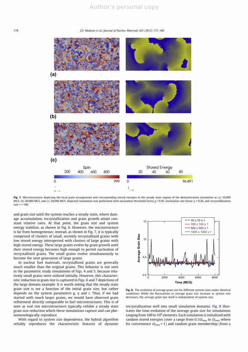
Xmax where for convenience Xmax = 1) and random grain member-ship (from a catalog of 1000 unique grain orientations); systemparameters were g = 95, g = 2, and r = 100. The evolution of systemenergy and grain size of one such run is shown in Fig. 6. Addition-ally, Fig. 7 shows the grain structure and local stored energy land-scape for portions of the simulation domain at the times denoted inFig. 6 by ‘a’, ‘b’, and ‘c’.
The local and global behavior of this simulation domain followthe general features of dynamic recrystallization [26]. Initially, thesystem energy increases and the grain size decreases drastically.When sufficient stored energy has been accumulated, recrystalliza-tion begins and the system energy decreases to a plateau. Typi-cally, this is followed by an oscillatory behavior in both energy
(a) (b)
5.0 x 10⁵
1.0 x 10⁶
1.5 x 10⁶
2.0 x 10⁶
2.5 x 10⁶
3.0 x 10⁶
3.5 x 10⁶
0 4000 8000 12000 16000
0.60, 0.2, 1.0, 1000.70, 0.2, 1.0, 1000.80, 0.2, 1.0, 1000.85, 0.2, 1.0, 1000.90, 0.2, 1.0, 100
Syst
em E
nerg
y
Time (MCS)0 4000 8000 12000 16000
0.60, 0.2, 1.0, 1000.80, 0.2, 1.0, 1000.90, 0.2, 1.0, 100
Gra
in S
ize
<R>
Time (MCS)
2.0
2.5
3.0
3.5
4.0
4.5
5.0
Fig. 4. Effect of increasing nucleation threshold factor g on (a) system energy (b) average grain size. The legend reports the simulation parameters as (g, g, boundary mobility,r). In the simulation methodology described here, boundary mobility is always unity.
(a) (b)
5.0 x 10⁵
1.0 x 10⁶
1.5 x 10⁶
2.0 x 10⁶
2.5 x 10⁶
3.0 x 10⁶
3.5 x 10⁶
0 4000 8000 12000 16000
0.9, 0.2, 1.0, 1000.9, 0.4, 1.0, 1000.9, 0.6, 1.0, 1000.9, 0.8, 1.0, 100
Syst
em E
nerg
y
Time (MCS)0 4000 8000 12000 16000
0.9, 0.2, 1.0, 1000.9, 0.4, 1.0, 1000.9, 0.8, 1.0, 100
Time (MCS)
2.0
2.5
3.0
3.5
4.0
4.5
5.0
Gra
in S
ize
<R>
Fig. 5. Effect of increasing nucleation rate factor g on (a) system energy (b) average grain size. The legend reports the simulation parameters as (g, g, boundary mobility, r). Inthe simulation methodology described here, boundary mobility is always unity.
(a) (b)
0.0
1.0 x 10⁸
2.0 x 10⁸
3.0 x 10⁸
4.0 x 10⁸
5.0 x 10⁸
0 10000 20000 30000
Syst
em E
nerg
y
Time (MCS)
a
b
c
0 10000 20000 30000
Gra
in S
ize
Time (MCS)
a
b
c
0.0
2.0
4.0
6.0
8.0
Fig. 6. (a) Total system energy and (b) average grain size in a 10,000 � 1500 � 1 demonstration simulation with parameters described in the text.
J.D. Madison et al. / Journal of Nuclear Materials 425 (2012) 173–180 177
Author's personal copy
and grain size until the system reaches a steady-state, where dam-age accumulation, recrystallization and grain growth attain con-stant relative rates. At that point, the grain size and systemenergy stabilize, as shown in Fig. 6. However, the microstructureis far from homogeneous; instead, as shown in Fig. 7, it is typicallycomprised of clusters of small, recently recrystallized grains withlow stored energy interspersed with clusters of large grains withhigh stored energy. These large grains evolve by grain growth untiltheir stored energy becomes high enough to permit nucleation ofrecrystallized grains. The small grains evolve simultaneously tobecome the next generation of large grains.
In nuclear fuel materials, recrystallized grains are generallymuch smaller than the original grains. This behavior is not seenin the parametric study simulations of Figs. 4 and 5, because rela-tively small grains were utilized initially. However, this character-istic reduction in grain size is captured in Figs. 6 and 7 depictions ofthe large domain example. It is worth noting that the steady stategrain size is not a function of the initial grain size, but ratherdepends on the system parameters g, g and r. Thus, if we hadstarted with much larger grains, we would have observed grainrefinement directly comparable to fuel microstructures. This is ofnote as real rim microstructures typically exhibit a steady stategrain size reduction which these simulations capture and can phe-nomenologically reproduce.
With regard to system size dependence, the hybrid algorithmreliably reproduces the characteristic features of dynamic
recrystallization well into small simulation domains. Fig. 8 illus-trates the time evolution of the average grain size for simulationsranging from 100 to 106 elements. Each simulation is initialized withrandom stored energies (over a range from 0.1Xmax to Xmax wherefor convenience Xmax = 1) and random grain membership (from a
Fig. 7. Microstructures depicting the local grain arrangement and corresponding stored energies in the steady state regime of the demonstration simulation at (a) 10,000MCS, (b) 20,000 MCS, and (c) 30,000 MCS. Depicted simulation was performed with nucleation threshold factor g = 0.95, nucleation rate factor g = 0.20, and recrystallizationrate r = 100.
0 2000 4000 6000 8000
500 x 500 x 1
10 x 10 x 1100 x 100 x 1
1000 x 1000 x 1
Ave
rage
Gra
in S
ize
Time (MCS)
0.0
5.0
10
15
Fig. 8. The evolution of average grain size for different system sizes under identicalconditions. While the fluctuations in average grain size increase as system sizedecreases, the average grain size itself is independent of system size.
178 J.D. Madison et al. / Journal of Nuclear Materials 425 (2012) 173–180

Author's personal copy
catalog of 1000 unique grain orientations); system parameters wereg = 90, g = 2, and r = 100. All systems consistently arrive at an aver-age grain size on the order of 3.75 elements when run under thesame initial conditions. Only when simulation domains becomesmaller than about 104 elements do the fluctuations in average grainsize approach deviations on the order of 3 times the average.
4. Discussion
While experimental investigations for improved economy,increased efficiency and heightened yield in nuclear fuels are ongo-ing [5,9,11,12], the access, cost and considerations associated withsuch studies are non-trivial at best. As such, the benefit of compu-tational approaches to the characterization and investigation ofirradiated nuclear fuels pose multiple advantages including theability to explore potential material evolution and microstructuraldevelopment beyond Nuclear Regulatory Commission (NRC)guidelines and consequently experimental observation.
While this model does provide opportunity to explore micro-structural evolution in nuclear fuels beyond experimental ranges,experiments or clearly scoped simulations are needed to informthe parameters employed in the model to realize its true effective-ness. In the model presented above, the energy associated withaccumulating lattice defects provides the driving force for nucle-ation and growth of recrystallized grains. This defect density ordamage energy can be estimated by experiments and/or simula-tion of irradiation damage in crystalline materials. In situ TEM ofmaterials being irradiated by ions can be used to estimate thenumber of defects per unit area or volume [40]. Alternately, othertechniques such as lattice parameter change [41] as a function ofirradiation can be used to estimate defect energies. Moleculardynamics have also been used to study the complete evolution ofdefect formation and annihilation over several picoseconds inUO2 as a function of ion energy [42], temperature [43,44] and localmicrostructure [45]. Experimental data of this kind combined withinsights obtained from simulation and analysis [46] can supply themodel with valuable estimates for defect energy accumulation inthe rim region and throughout a fuel cross-section.
4.1. Benefits
The importance of understanding the development and evolu-tion of this rim structure is to allow prediction of fuel performanceduring normal operation, fission product release during accidents,properties of spent fuels during long-term storage, and other per-formance characteristics. It may also prove useful for fuel designamong high burn-up fuels, MOX fuels or other advanced fuels byproviding an expectation of microstructural variations as a func-tion of burn-up, evolution and fuel life.
A model that can incorporate all the physical phenomena neces-sary to simulate dynamic recrystallization observed in the outerrim of high-burnup LWR fuels has been presented. The kinetic ratesfor grain boundary mobility driven by curvature and by recrystalli-zation can be varied relative to one another. Additionally, the nucle-ation conditions can also be varied to control the activation energyrequired for nucleation, by setting a threshold energy factor, g, andnucleation rate factor, g. These simulation parameters can beselected to match the varied conditions of different fuels and reac-tors to develop understanding and predictive capabilities foradvanced fuel design or investigation of high-burnup conditions.
4.2. Limitations
Currently, the model presented does not incorporate the effectsof porosity, fission gas bubbles or any positional dependence in the
incremental damage accumulation supplied to the system overtime. The goal here is isolate the motivating factors and resultanteffects of dynamic recrystallization in a computational frameworkapplicable to nuclear fuels. As such, it is desirable to de-couple fur-ther advanced evolutionary processes from those related to graindevelopment, grain size and irradiation damage accumulation. For-tunately, previous and ongoing work has been performed to modelthe formation of enhanced microstructural processes in fuel mate-rials [47]. Of these efforts, investigations of porosity formation andtransport [48] have been performed upon a similar framework asthe current study making future synergies with such a model, verylikely in the near future. With regard to the positional dependenceof irradiation damage, the ability to implement a time and positiondependent energy accumulation is present, however experimentaldata detailing irradiation damage profiles as functions of time andposition in the fuel material itself need further development.
4.3. Areas for future work
Next steps for this model shall include incorporation of fissiongas generation, porosity formation, and species diffusion. Addition-ally, simulation domain sizing commensurate with the globalexpectation and observations of irradiation damage with radialposition will be pursued toward a more robust application of ther-mal gradients that will, in turn, influence grain boundary mobilityand interactions.
5. Conclusions
- A hybrid simulation combining models for damage accumula-tion, nucleation of damage-free regions, recrystallization, andgrain growth has successfully demonstrated dissipation of irra-diation damage through a dynamic recrystallization and graingrowth process. The components of the model include a phe-nomenological model for damage accumulation and nucleation,a Cellular Automaton (CA) model for the growth and impinge-ment of recrystallized grains, and a kinetic Monte Carlo (kMC)Potts model for subsequent grain growth.
- During dynamic recrystallization, initial oscillations in systemenergy and grain size eventually stabilize to a steady state,where damage accumulation, recrystallization and grain growthattain constant relative rates. At this point, the grain size andsystem energy resolve to constant values that are independentof the initial state. In this regime, the microstructure is com-prised of clusters of small, recently recrystallized grains withlow stored energy interspersed with clusters of large grains withhigh stored energy.
- Parametric simulations indicate that increasing the nucleationthreshold factor (while holding all other factors constant) resultin increased total system energy and larger average grain size,while increasing the nucleation rate (while holding all otherfactors constant) result in decreased total system energy andsmaller average grain size.
- While large-scale runs are useful for capturing the scale of real-istic microstructures, the hybrid algorithm effectively providescharacteristic trends in grain size reduction, relative scalingand microstructural evolution with abbreviated domains downto 1002 elements.
References
[1] M.L. Blieberg, R.M. Berman, B. Lustman, Effects of high burn-up on oxideceramic fuels, in: IAEA, Radiation Damage in Solids and Reactor Materials,Vienna, 1963, p. 319.
[2] H. Matzke, H. Blank, M. Coquerelle, K. Lassmann, I.L.F. Ray, C. Ronchi, C.T.Walker, J. Nucl. Mater. 166 (1989) 165–178.
J.D. Madison et al. / Journal of Nuclear Materials 425 (2012) 173–180 179

Author's personal copy
[3] N. Lozano, L. Desgranges, D. Aymes, J.C. Niepce, J. Nucl. Mater. 257 (1998)78–87.
[4] K. Une, K. Nogita, T. Shiratori, K. Hayashi, J. Nucl. Mater. 288 (2001) 20–28.[5] C.T. Walker, D. Staicu, M. Sheindlin, D. Papaioannou, W. Goll, F. Sontheimer, J.
Nucl. Mater. 350 (2006) 19–39.[6] J. Noirot, I. Aubrun, L. Desgranges, K. Hanifi, J. Lamontagne, B. Pasquet, C. Valot,
P. Blanpain, H. Cognon, Nucl. Eng. Technol. 41 (2009) 155–162.[7] J. Rest, G.L. Hofman, J. Nucl. Mater. 210 (1994) 187–202.[8] J. Spino, D. Papaioannou, J. Nucl. Mater. 281 (2000) 146–162.[9] J. Spino, A.D. Stalios, H. Santa Cruz, D. Baron, J. Nucl. Mater. 354 (2006) 66–84.
[10] M.E. Cunningham, M.D. Freshley, D.D. Lanning, J. Nucl. Mater. 188 (1992)19–27.
[11] R. Manzel, C.T. Walker, J. Nucl. Mater. 301 (2002) 170–182.[12] J. Spino, J. Cobos-Sabate, F. Rousseau, J. Nucl. Mater. 322 (2003) 204–216.[13] Y.H. Koo, B.H. Lee, J.Y. Oh, K.-W. Song, Nucl. Technol. 164 (2008) 337–347.[14] I.L.F. Ray, H. Matzke, J. Nucl. Mater. 250 (1997) 242–243.[15] J. Spino, K. Vennix, M. Coquerelle, J. Nucl. Mater. 231 (1996) 179–190.[16] L.E. Thomas, C.E. Beyer, L.A. Charlot, J. Nucl. Mater. 188 (1992) 80–89.[17] A.D. Rollett, D.J. Srolovitz, R.D. Doherty, M.P. Anderson, Acta Metall. 37 (1989)
627–639.[18] D.J. Srolovitz, G.S. Grest, M.P. Anderson, Acta Metall. Mater. 34 (1986)
1833–1845.[19] D.J. Srolovitz, G.S. Grest, M.P. Anderson, A.D. Rollett, Acta Metall. Mater. 36
(1988) 2115–2128.[20] A.D. Rollett, D.J. Srolovitz, M.P. Anderson, R.D. Doherty, Acta Metall. Mater. 40
(1992) 3475–3495.[21] D. Raabe, Philos. Mag. A 79 (1999) 2339–2358.[22] V.Y. Novikov, E.A. Zalem, Y.A. Smirnova, Acta Metall. Mater. 40 (1992)
3459–3464.[23] A.D. Rollett, M.J. Luton, D.J. Srolovitz, Acta Metall. Mater. 40 (1992) 43–55.[24] P. Peczak, Acta Metall. Mater. 43 (1995) 1279–1291.[25] H.W. Hesselbarth, I.R. Gobel, Acta Metall. Mater. 39 (1991) 2135–2143.[26] F.J. Humphreys, M. Hatherly, Recrystallization and Related Annealing
Phenomena, second ed., Elsevier, Oxford, 2004.[27] A.D. Rollett, D. Raabe, Comput. Mater. Sci. 21 (2001) 69–78.[28] K. Janssens, Cellular automata, in: K.G.F. Janssens, D. Raabe, E. Kozeschnik,
M.A. Miodownik, B. Nestler (Eds.), Computational Materials Engineering: An
Introduction to Microstructure Evolution, Elsevier Inc., Burlington, MA, 2007,pp. 109–150.
[29] D. Raabe, Cellular, lattice gas, and boltzmann automata, in: D. Raabe, F. Roters,F. Barlat, L.Q. Chen (Eds.), Continuum Scale Simulation of EngineeringMaterials: Fundamentals-Microstructures-Process Applications, Wiley-VCH,Strauss GmbH, 2004, pp. 57–76.
[30] D. Raabe, Comput. Mater. Sci. 19 (2000) 13–26.[31] D. Raabe, Adv. Eng. Mater. 3 (2001) 745–752.[32] G.S. Grest, D.J. Srolovitz, M.P. Anderson, Acta Metall. 33 (1985)
509–520.[33] D.J. Srolovitz, M.P. Anderson, G.S. Grest, P.S. Sahni, Acta Metall. 32 (1984)
1429–1438.[34] A.L. Garcia, V. Tikare, E.A. Holm, Scripta Mater. 59 (2008) 661–664.[35] D.J. Srolovitz, M.P. Anderson, P.S. Sahni, G.S. Grest, Acta Metall. 32 (1984)
793–802.[36] M.P. Anderson, D.J. Srolovitz, G.S. Grest, P.S. Sahni, Acta Metall. 32 (1984)
783–791.[37] V. Tikare, E.A. Holm, D. Fan, L.Q. Chen, Acta Mater. 47 (1999) 363–371.[38] E.A. Holm, J.A. Glazier, D.J. Srolovitz, G.S. Grest, Phys. Rev. A 43 (1991)
2662–2668.[39] S. Plimpton, SPPARKS Kinetic Monte Carlo Simulator, <http://
www.cs.sandia.gov/~sjplimp/spparks.html>, 2010.[40] T. Wiss, H. Matzke, C. Trautmann, M. Toulemonde, S. Klaumunzer, Nucl.
Instrum Methods Phys. Res. B 122 (1997) 583–588.[41] K. Hayashi, H. Kikuchi, K. Fukuda, J. Nucl. Mater. 284 (1997) 191–195.[42] G. Martin, P. Garcia, L. Van Brutzel, B. Dorado, S. Maillard, Nucl. Instrum.
Methods Phys. Res. B 269 (2011) 1727–1730.[43] K. Morishita, N. Sekimura, T. Diaz de la Rubia, J. Nucl. Mater. 248 (1997)
400–404.[44] L. Van Brutzel, M. Rarivomanantsoa, J. Nucl. Mater. 358 (2006) 209–216.[45] V.V. Likhanskii, A.A. Sorokin, O.V. Khoruzhii, At. Energy 96 (2004)
102–110.[46] D. Olander, J. Nucl. Mater. 399 (2010) 236–239.[47] R. Devanathan, L. Van Brutzel, A. Chartier, C. Gueneau, A.E. Mattson, V. Tikare,
T. Bartel, T. Besmann, M. Stan, P.V. Van Uffelen, Energy Environ. Sci. 3 (2010)1406–1426.
[48] V. Tikare, E.A. Holm, J. Am. Ceram. Soc. 81 (1998) 480–484.
180 J.D. Madison et al. / Journal of Nuclear Materials 425 (2012) 173–180