a high-throughput strategy to screen 2d crystallization ... · a high-throughput strategy to screen...
TRANSCRIPT

Available online at www.sciencedirect.comJournal of
www.elsevier.com/locate/yjsbi
Journal of Structural Biology 160 (2007) 295–304
StructuralBiology
A high-throughput strategy to screen 2D crystallizationtrials of membrane proteins
Martin Vink a, KD Derr a, James Love a,b, David L. Stokes a,c,Iban Ubarretxena-Belandia d,*
a The New York Structural Biology Center, 89 Convent Avenue, New York, NY 10027, USAb New York Consortium on Membrane Protein Structure, 89 Convent Avenue, New York, NY 10027, USA
c Skirball Institute of Biomolecular Medicine and Department of Cell Biology, New York University School of Medicine,
540 First Avenue, New York, NY 10016, USAd Department of Structural and Chemical Biology, Mount Sinai School of Medicine, 1425 Madison Avenue, New York, NY 10029, USA
Received 2 May 2007; received in revised form 6 September 2007; accepted 7 September 2007Available online 14 September 2007
Abstract
Electron microscopy of two-dimensional (2D) crystals has demonstrated potential for structure determination of membrane proteins.Technical limitations in large-scale crystallization screens have, however, prevented a major breakthrough in the routine application ofthis technology. Dialysis is generally used for detergent removal and reconstitution of the protein into a lipid bilayer, and devices fortesting numerous conditions in parallel are not readily available. Furthermore, the small size of resulting 2D crystals requires electronmicroscopy to evaluate the results and automation of the necessary steps is essential to achieve a reasonable throughput. We havedesigned a crystallization block, using standard microplate dimensions, by which 96 unique samples can be dialyzed simultaneouslyagainst 96 different buffers and have demonstrated that the rate of detergent dialysis is comparable to those obtained with conventionaldialysis devices. A liquid-handling robot was employed to set up 2D crystallization trials with the membrane proteins CopA fromArchaeoglobus fulgidus and light-harvesting complex II (LH2) from Rhodobacter sphaeroides. For CopA, 1 week of dialysis yielded tubu-lar crystals and, for LH2, large and well-ordered vesicular 2D crystals were obtained after 24 h, illustrating the feasibility of thisapproach. Combined with a high-throughput procedure for preparation of EM-grids and automation of the subsequent negative stainingstep, the crystallization block offers a novel pipeline that promises to speed up large-scale screening of 2D crystallization and to increasethe likelihood of producing well-ordered crystals for analysis by electron crystallography.� 2007 Elsevier Inc. All rights reserved.
Keywords: Two-dimensional (2D) crystals; Membrane proteins; Electron crystallography; High-throughput screening; Membrane protein reconstitution;Negative staining; 96-Well format; Crystallization block; Dialysis block
1. Introduction
Integral membrane proteins (IMPs)1 comprise approxi-mately 30% of the genes encoded in eubacterial, archaebac-terial and eukaryotic genomes (Stevens and Arkin, 2000;
1047-8477/$ - see front matter � 2007 Elsevier Inc. All rights reserved.
doi:10.1016/j.jsb.2007.09.003
* Corresponding author. Fax: +1 212 849 2456.E-mail address: [email protected] (I. Ubarretxena-Belandia).
1 Abbreviations used: IMP, integral membrane protein; LPR, lipid-to-protene(8)dodecyl ether; OG, n-octyl-b-D-glucopyranoside; LDAO, n-dodecyl-N,critical micelle concentration; LH2, light-harvesting complex II; EM, electron
Wallin and von Heijne, 1998), and play essential roles in cel-lular signaling and metabolism as receptors, enzymes, chan-nels, transporters and structural proteins. IMPs are alsopivotal in medicine and constitute the target of over 50%of current therapeutic drugs (Drews, 2000; Imming et al.,
ein ratio; DDM, n-dodecyl-b-D-maltopyranoside; C12E8, polyoxyethyl-N-dimethylamine-N-oxide; DOPC, dioleoyl phosphatidylcholine; CMC,microscopy.

296 M. Vink et al. / Journal of Structural Biology 160 (2007) 295–304
2006). Despite the relevance of membrane proteins to cellbiology and to therapeutic medicine, to date only �125unique membrane protein structures have been depositedin the protein data bank (http://blanco.biomol.uci.edu/Membrane_Proteins_xtal.html). One reason for this hugeknowledge-gap is that the prevalent protein structure deter-mination methods, X-ray crystallography and NMR spec-troscopy, suffer from technical limitations when it comesto IMPs. Unlike the soluble proteins routinely studied bythese techniques, IMPs are embedded in the hydrophobicenvironment of the lipid bilayer and their amphiphilic nat-ure hinders our ability to study them. Specifically, the mainhurdles hampering membrane protein structure determina-tion are: (i) problems in the routine over-expression of IMPswith native tertiary and quaternary structure; (ii) the loss ofbiological activity when IMPs are extracted from theirnative membrane environment with detergent; (iii) the largesize of membrane protein/detergent complexes, which pre-vents the application of currently available solution NMRmethods; and (iv) the difficulty in obtaining well-diffractingthree-dimensional (3D) crystals for X-ray analysis. Theseproblems are particularly severe for large, complex mem-brane proteins from eukaryotic origin.
An alternative approach to X-ray crystallography andNMR for the determination of membrane protein structureis electron crystallography of two-dimensional (2D) crys-tals (Henderson and Unwin, 1975). Indeed, this methodol-ogy has yielded atomic structures in the case ofbacteriorhodopsin (Henderson et al., 1990), plant light-harvesting complex (Kuhlbrandt et al., 1994), human redcell aquaporin-1 (Murata et al., 2000), eye lens aquapo-rin-0 (Gonen et al., 2005), rat aquaporin-4 (Hiroakiet al., 2006), glutathione transferase (Holm et al., 2006)and acetylcholine receptor (Unwin, 2005). The 3D struc-ture of approximately 20 other unique membrane proteinshave been determined to medium-resolution (5–8 A), andcontinuing efforts are expected to produce atomic modelsin the near future (e.g. Hirai et al., 2002; Kukulski et al.,2005; Ubarretxena-Belandia et al., 2003). Electron crystal-lography is particularly well suited for IMPs that have anatural propensity to form 2D crystals within their nativemembranes. Unfortunately, these so-called ‘‘in situ’’ 2Dcrystals are quite rare and have only been found in specialcases, e.g. when the concentration of the protein within thenative membrane is high enough. Notable examples arebacteriorhodopsin from Halobacterium halobium (Hender-son and Unwin, 1975) and Ca2+-ATPase from mammaliansarcoplasmic reticulum (Dux and Martonosi, 1983; Xuet al., 2002) More generally, 2D crystals have been grownby reconstitution of purified, detergent-solubilized IMPsinto lipid bilayers under defined conditions (for reviewssee Jap et al., 1992; Kuhlbrandt, 1992; Mosser, 2001).Reconstitution involves the controlled removal of deter-gent, either by dialysis (Kuhlbrandt, 1992), controlled dilu-tion (Remigy et al., 2003), adsorption onto a hydrophobicresin (Rigaud et al., 1997) or complexation to cyclodextrins(Signorell et al., 2006) in presence of a defined lipid-to-pro-
tein ratio (LPR). By achieving high density of a single pro-tein species constrained to a 2D lipid bilayer, formation ofa regular array—or 2D crystal—within this bilayerbecomes relatively favorable.
2D crystallization of IMPs offers distinct advantages.Generally speaking, 2D crystallization can be performedat approximately 10-fold lower protein concentrations(0.4–1 mg/ml), than the concentrations required for 3Dcrystallization or for NMR data collection. Thus, only asmall amount of material is required, an important consid-eration for IMPs with low expression levels, and sampleaggregation that is common at high concentration of IMPscan be avoided. Moreover, 2D crystals provide a naturallipidic environment that is more likely to preserve thenative conformation of the protein. Still, obtaining 2Dcrystals with the size and crystalline order required forstructure determination by electron microscopy (EM)remains a challenge.
Identifying conditions for producing well-ordered crys-tals represents a significant bottleneck for any form of crys-tallography. Because these conditions are determinedempirically there is a need for comprehensive screening.Indeed, rapid screening for 3D crystallization conditionshas been critical in the recent explosion of X-ray crystallog-raphy, where a shotgun approach involving a large numberof variables is generally required to produce crystals thatdiffract to high-resolution (Rees, 2001). Such rapid screen-ing has been facilitated by the use of liquid handling robotsto set up 24- or 96-well trays for vapor diffusion that can berapidly screened by optical microscopy. In contrast, set upof dialysis trials for 2D crystallization has been neither fastnor automated. Furthermore, the small size of resulting 2Dcrystals (1–10 lm diameter and 5–10 nm thickness)requires electron microscopy to evaluate the results. In par-ticular, each trial condition must be transferred to an EMgrid, stained and inserted through an airlock into an elec-tron microscope in a holder that typically holds just onegrid at a time.
For this report, we have developed strategies for auto-mating the screening of 2D crystallization of membraneproteins. We have designed a 96-well block for paralleldialysis trials, and employed a liquid-handling robot, bothfor setting up these trials, and for staining the EM speci-mens required for evaluating the screen. Two IMPs wereused to evaluate the performance of the 96-well crystalliza-tion block and the quality of the staining procedure,namely CopA from Archaeoglobus fulgidus and light-har-vesting complex II (LH2) from Rhodobacter sphaeroides.
We also describe two alternatives for automated imagingof these samples within the electron microscope.
2. Materials and methods
2.1. Chemicals
The chemicals DDM (n-dodecyl-b-D-maltopyranoside),C12E8 (polyoxyethylene(8)dodecyl ether), OG (n-octyl-b-
M. Vink et al. / Journal of Structural Biology 160 (2007) 295–304 297
D-glucopyranoside), LDAO (n-dodecyl-N,N-dimethyl-amine-N-oxide), and DOPC (dioleoyl phosphatidylcholine)were of the highest commercially available grade and werepurchased from Anatrace (DDM, LDAO, OG), Nikkol(C12E8) and Avanti Polar Lipids (DOPC).
2.2. Quantification of detergent removal
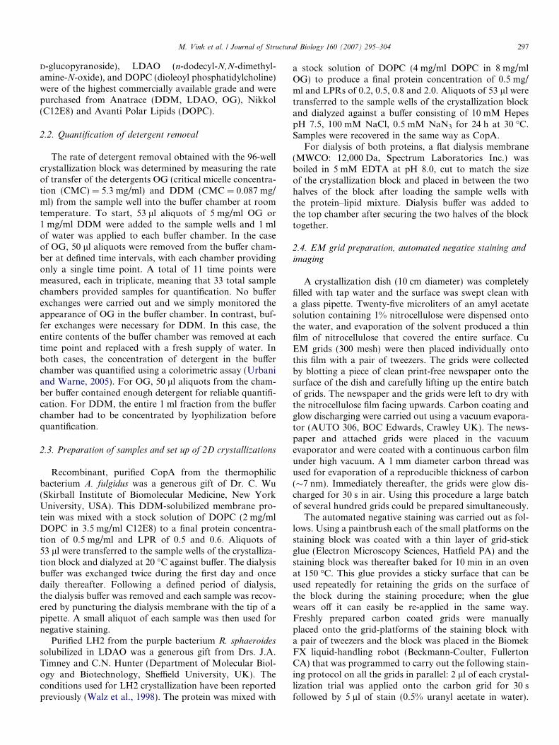
The rate of detergent removal obtained with the 96-wellcrystallization block was determined by measuring the rateof transfer of the detergents OG (critical micelle concentra-tion (CMC) = 5.3 mg/ml) and DDM (CMC = 0.087 mg/ml) from the sample well into the buffer chamber at roomtemperature. To start, 53 ll aliquots of 5 mg/ml OG or1 mg/ml DDM were added to the sample wells and 1 mlof water was applied to each buffer chamber. In the caseof OG, 50 ll aliquots were removed from the buffer cham-ber at defined time intervals, with each chamber providingonly a single time point. A total of 11 time points weremeasured, each in triplicate, meaning that 33 total samplechambers provided samples for quantification. No bufferexchanges were carried out and we simply monitored theappearance of OG in the buffer chamber. In contrast, buf-fer exchanges were necessary for DDM. In this case, theentire contents of the buffer chamber was removed at eachtime point and replaced with a fresh supply of water. Inboth cases, the concentration of detergent in the bufferchamber was quantified using a colorimetric assay (Urbaniand Warne, 2005). For OG, 50 ll aliquots from the cham-ber buffer contained enough detergent for reliable quantifi-cation. For DDM, the entire 1 ml fraction from the bufferchamber had to be concentrated by lyophilization beforequantification.
2.3. Preparation of samples and set up of 2D crystallizations
Recombinant, purified CopA from the thermophilicbacterium A. fulgidus was a generous gift of Dr. C. Wu(Skirball Institute of Biomolecular Medicine, New YorkUniversity, USA). This DDM-solubilized membrane pro-tein was mixed with a stock solution of DOPC (2 mg/mlDOPC in 3.5 mg/ml C12E8) to a final protein concentra-tion of 0.5 mg/ml and LPR of 0.5 and 0.6. Aliquots of53 ll were transferred to the sample wells of the crystalliza-tion block and dialyzed at 20 �C against buffer. The dialysisbuffer was exchanged twice during the first day and oncedaily thereafter. Following a defined period of dialysis,the dialysis buffer was removed and each sample was recov-ered by puncturing the dialysis membrane with the tip of apipette. A small aliquot of each sample was then used fornegative staining.
Purified LH2 from the purple bacterium R. sphaeroides
solubilized in LDAO was a generous gift from Drs. J.A.Timney and C.N. Hunter (Department of Molecular Biol-ogy and Biotechnology, Sheffield University, UK). Theconditions used for LH2 crystallization have been reportedpreviously (Walz et al., 1998). The protein was mixed with
a stock solution of DOPC (4 mg/ml DOPC in 8 mg/mlOG) to produce a final protein concentration of 0.5 mg/ml and LPRs of 0.2, 0.5, 0.8 and 2.0. Aliquots of 53 ll weretransferred to the sample wells of the crystallization blockand dialyzed against a buffer consisting of 10 mM HepespH 7.5, 100 mM NaCl, 0.5 mM NaN3 for 24 h at 30 �C.Samples were recovered in the same way as CopA.
For dialysis of both proteins, a flat dialysis membrane(MWCO: 12,000 Da, Spectrum Laboratories Inc.) wasboiled in 5 mM EDTA at pH 8.0, cut to match the sizeof the crystallization block and placed in between the twohalves of the block after loading the sample wells withthe protein–lipid mixture. Dialysis buffer was added tothe top chamber after securing the two halves of the blocktogether.
2.4. EM grid preparation, automated negative staining and
imaging
A crystallization dish (10 cm diameter) was completelyfilled with tap water and the surface was swept clean witha glass pipette. Twenty-five microliters of an amyl acetatesolution containing 1% nitrocellulose were dispensed ontothe water, and evaporation of the solvent produced a thinfilm of nitrocellulose that covered the entire surface. CuEM grids (300 mesh) were then placed individually ontothis film with a pair of tweezers. The grids were collectedby blotting a piece of clean print-free newspaper onto thesurface of the dish and carefully lifting up the entire batchof grids. The newspaper and the grids were left to dry withthe nitrocellulose film facing upwards. Carbon coating andglow discharging were carried out using a vacuum evapora-tor (AUTO 306, BOC Edwards, Crawley UK). The news-paper and attached grids were placed in the vacuumevaporator and were coated with a continuous carbon filmunder high vacuum. A 1 mm diameter carbon thread wasused for evaporation of a reproducible thickness of carbon(�7 nm). Immediately thereafter, the grids were glow dis-charged for 30 s in air. Using this procedure a large batchof several hundred grids could be prepared simultaneously.
The automated negative staining was carried out as fol-lows. Using a paintbrush each of the small platforms on thestaining block was coated with a thin layer of grid-stickglue (Electron Microscopy Sciences, Hatfield PA) and thestaining block was thereafter baked for 10 min in an ovenat 150 �C. This glue provides a sticky surface that can beused repeatedly for retaining the grids on the surface ofthe block during the staining procedure; when the gluewears off it can easily be re-applied in the same way.Freshly prepared carbon coated grids were manuallyplaced onto the grid-platforms of the staining block witha pair of tweezers and the block was placed in the BiomekFX liquid-handling robot (Beckmann-Coulter, FullertonCA) that was programmed to carry out the following stain-ing protocol on all the grids in parallel: 2 ll of each crystal-lization trial was applied onto the carbon grid for 30 sfollowed by 5 ll of stain (0.5% uranyl acetate in water).

298 M. Vink et al. / Journal of Structural Biology 160 (2007) 295–304
After removing 5 ll of this solution, another 5 ll of stainwas applied onto the grid followed by an immediateremoval of 5 ll of solution. This procedure was repeatedone more time and in the final aspiration step all remainingliquid was removed from the grids, which were thenallowed to dry. Samples were examined in a JEM-1230transmission electron microscope (JEOL, Tokyo Japan)at an accelerating voltage of 80 keV and images wererecorded on a 1K · 1K CCD camera (Erlangshen, GatanInc., Pleasanton CA).
3. Results and discussion
3.1. Design and construction of a 96-well 2D crystallization
block
2D crystallization involves the removal of detergent inthe presence of lipid in order to reconstitute a given IMPinto a lipid bilayer under conditions that are amenable tothe formation of a 2D crystal. Dialysis is the most commonmethod for detergent removal and has generally involvedlaborious procedures involving the use of dialysis bags, cas-settes or buttons (Kuhlbrandt, 1992), which limit the num-ber of parallel conditions that an investigator can manage.Several devices for parallel dialysis have been described for2D crystal screening but, in general, these provide a limitednumber of chambers for testing different conditions and donot interface well with liquid-handling robotic systemsoperating on a 96-well microtiter format (Engel et al.,1998; Jap et al., 1992; Paul et al., 1992). 96-well dialysisplates are also commercially available, but they are severelylimited since all 96 different protein samples have to be dia-lyzed against a common buffer (e.g. the 96-Well Dispo-Dia-lyser from The Nest Group). Ideally, a 96-wellcrystallization device should offer the possibility to dialyze96 different crystallization trials against 96 unique dialysisbuffers. Such a device will offer enhanced flexibility toscreen a given protein solution, with a defined lipid typeand LPR, against a range of dialysis buffers having variouspH’s, ionic strengths, inhibitors or substrate analogs.
We have therefore designed a crystallization block usingthe geometry and dimensions of the standard 96-well for-mat to allow for automation of crystallization trials. Thisblock can be cheaply reproduced and allows for simulta-neous dialysis against 96 different buffers (Fig. 1). Theblock consists of a lower part that accommodates the dial-ysate wells and an upper part containing the chambers forthe dialysis buffer. The dialysis membrane is placed in thespace in between the upper and lower parts. SBS standardsfor micro-plate dimensions were used for the outer dimen-sions (8.55 · 12.8 cm) of the block and for the spacing ofthe wells (9 mm center-to-center, for a full set of standarddimensions, refer to http://www.sbsonline.org/msdc/). Toallow for visual inspection during the dialysis process, theblock was made out of transparent acrylic plastic (Fig. 1c).
The sample wells were designed to optimize the contactarea between dialysate and dialysis buffer and thus maxi-
mize the rate of detergent removal. These wells were there-fore made 5 mm in diameter but only 3 mm deep, with a50 ll capacity, and with a conical bottom to facilitate sam-ple removal after completion of dialysis (Fig. 1b). Thechamber for the dialysis buffer in the upper part of the crys-tallization block has a 6 mm diameter and 37 mm heightwith a capacity of 1.1 ml. Each exchange of dialysis bufferthus dilutes the sample >20-fold. The pipette tips must ulti-mately puncture the dialysis membrane to retrieve the dial-ysate. Therefore, the standard pipette tip length used by theBiomek FX liquid handler, employed for automation ofthe dialysis process, constrains the height of the bufferchambers, and hence their capacity.
To assemble the crystallization block, samples wereloaded into the dialysate wells, the upper part was invertedand the wet dialysis membrane was placed on top. Air bub-bles and folds were carefully removed from the dialysismembrane and the upper block was placed on top of thelower block using the metal guide pins located in the oppo-site corners of the lower block (diameter 4.5 mm). Theseguide pins ensure that the block faces remain parallel dur-ing the assembly. After establishing contact, the two partswere secured with six stainless steel screws on the long sideof the block (Fig. 1a and c). Initially these screws tappeddirectly into the acrylic plastic on the lower part of theblock, but we found that tightening the screws caused theacrylic to crack. To distribute the force more evenly, theupper edge of the block was cut away and replaced by analuminum bar (6 · 6 · 100 mm) with holes to accommo-date the screws. Likewise, the edge of the lower blockwas replaced with an aluminum bar of the same dimensionsas the upper bar with threaded receptacles to receive thescrews (Fig. 1a and c). The aluminum bars were glued ontothe block by the use of 5-min epoxy.
Initially, we did not use the silicone gaskets shown inFig. 1 and despite parallel and level surfaces on both theupper and lower faces of the block and care in sealingthe blocks, leakage between adjoining wells was substan-tial. When grease was applied onto the upper and lowerblock faces, leakage was significantly reduced. However,the grease had a tendency to spread into the wells andpartly cover the dialysis interface, thus diminishing the rateof dialysis. Furthermore, the use of grease made the partsslippery and difficult to handle. Next, we applied a smallring of silicone caulk around the circumference of eachwell—both upper and lower block faces—and allowed tocure. The compressibility and inertness of the silicone pro-duced an ideal seal and almost no leakage was observedbetween the wells. However, fresh silicone rings had to bereapplied for each new dialysis trial and this process wastime-consuming. In our final design, a soft silicone sheet(McMaster-Carr, #9010K811) has been fashioned into agasket on either side of the dialysis sheet. Having a thick-ness of only 0.8 mm, this sheet is very flexible yet robustand possesses both the compressibility and inertness ofthe silicone caulk. The silicone sheet was cut to the sizeof the crystallization block and holes corresponding to

metal guide
tightening screws
lower blockwith sample wells
upper blockwith buffer chambers
6mm
5mm3mm
37mm
dialysismembrane
silicone sheet
silicone sheet
Buffer chamber
Sample well
silicone sheet
dialysismembrane
37mm
silicone sheet
silicone sheet
18mm
aluminium bar
metal guide
Fig. 1. The 96-well 2D crystallization block. (a) A schematic representation of the crystallization block is shown. The metal guides are positioneddiagonally in two of the corners of the lower block to aid the assembly of the upper and lower block parts, and the six screws are used to keep the blocktightly sealed after assembly. Note that the silicone sheets are necessary both above and below the dialysis membrane to prevent leakage. (b) View of anindividual dialysis unit illustrating dimensions of the sample well and the buffer chamber. (c) Photo of the crystallization block prior to assembly in whichvarious parts are shown. The dialysis membrane and one of the silicone sheets are omitted for clarity.
M. Vink et al. / Journal of Structural Biology 160 (2007) 295–304 299
the buffer chambers and/or sample wells were punched inthe sheet using a custom-made cork-borer with the upperblock as a template for the positions of the holes. The sil-icone is intrinsically sticky and, once centered over theholes, remains tightly stuck to the surfaces of the crystalli-zation block. Furthermore, the silicone is easy to clean andreusable. Most importantly, leakage between adjoiningwells was undetectable when the silicone sheets were usedon both sides of the dialysis membrane (Fig. 1).
During assembly of the crystallization block it was dis-covered that small air bubbles formed in the sample wellsin the contact area between the chambers and the dialysismembrane. However, optimizing the volume in the samplewell minimized these air bubbles. With the added thicknessof the silicone gasket, the optimal volume of loaded samplewas 53 ll. Undoubtedly, air bubbles hamper dialysis sincethey reduce the contact area between sample and buffer,however, due to the miniscule size of the bubbles underoptimal loading conditions, their effect on the rate of dial-ysis is probably very limited.
The Biomek FX liquid-handling robot allows for auto-mation of crystallization trials using the crystallizationblock. This robot loads protein samples in the dialysis wellsand, after assembly of the block, carries out buffer addi-tion, exchange and removal. At the end of the crystalliza-tion period, the robot retrieves the dialysate by punchinga hole through the dialysis membrane transferring the sam-
ples either to another microtiter plate for storage ordirectly onto EM grids for staining. Moreover, in betweenthe buffer exchange steps, the robot can be used to mix orto exchange the dialysis buffer, thus minimizing gradientsfrom building up and slowing down the rate of dialysis.
3.2. Design and implementation of a negative staining
procedure in a 96-well format
A high-throughput workflow for the screening of 2Dcrystals includes not only dialysis, but also procedures forpreparing EM grids and for staining samples in a reproduc-ible and parallelized way. Using a thin plastic layer as asupport for carbon film is a common strategy for preparingrobust carbon substrates for negative staining, and can befaster than floating evaporated carbon off a mica surface(Harris, 1997). Preparation of a batch of grids withattached plastic can be accomplished within minutes bypipetting nitrocellulose dissolved in amyl acetate onto aclean water surface, and allowing the amyl acetate to evap-orate. The resulting plastic film provides a resilient sub-strate for supporting Cu EM grids on the water surface,which can then be picked up tout ensemble with a pieceof newspaper. Since the ensuing carbon evaporation andglow discharge are performed using the same vacuum evap-orator operated in different modes, the throughput for car-bon-coated grid production is high.

300 M. Vink et al. / Journal of Structural Biology 160 (2007) 295–304
Unlike detergent removal by dialysis, negative stainingof samples is not innately time consuming. Nevertheless,negative staining requires multiple steps of pipetting andblotting and thus constitutes a significant bottleneck in ahigh-throughput screen. However, these steps are amenableto automation with a liquid-handling robot. A grid-stain-ing plate (Fig. 2) made up from 96 cubical platforms, cutfrom aluminum and spaced according to standard micro-plate dimensions (http://www.sbsonline.org/msdc/) wasdeveloped. EM grids were placed atop these cubical plat-forms, whose 2 mm dimension was slightly smaller thanthe 3 mm diameter of a conventional EM grid. These plat-forms allow easy placement of grids with forceps and alsominimize the wicking of solution to the backside of thegrids. The robot was then used to apply specimens andto stain the grids (see Section 2). We note that althoughwe used forceps, a suction pipette (Vacuum Pick Up Sys-tem, Electron Microscopy Sciences) for handling the gridsrepresents a good alternative that should be considered andthat could lend itself to further automation with a roboticarm.
Early trials with the grid-staining plate focused on thetask of attaching the grids onto the platform. If the inter-action was too strong the grids became deformed or torewhen trying to remove them after staining. On the otherhand without an adhesive, the grids were displaced or evenremoved by capillary action during the pipetting steps
9mm2mm
2mm2mm
EM grid
Fig. 2. The 96-grid staining block. (a) A diagram of the negative stainingblock displaying the cubical platforms supporting the grids during thestaining process. The carbon-coated EM grids are attached onto theplatform one-by-one using Grid Stick Glue as adhesive. (b) A close-up ofthe staining block (white arrow) during one of the pipetting steps by theBiomek FX liquid-handling robot. Microtiter trays holding samples andnegative stain surround the block (black arrows).
needed in the staining protocol. Glycerol and vacuumgrease (Fomblin) were evaluated as adhesives, but theirgreasy texture made the grids difficult to handle. A solutionof 2% sorbitol in distilled water performed well as an adhe-sive and did not affect carbon film quality. For adhesion, asmall amount of sorbitol solution was spread onto eachplatform using a paintbrush, grids were placed on the plat-forms and the solvent was allowed to evaporate, thusattaching the individual grids to their staining platforms.However, a fresh application of sorbitol was required forevery round of staining and the evaporation step took aconsiderable amount of time, thus detracting from our goalof high-throughput. A more effective alternative is to applya thin layer of Grid-Stick Glue (Electron Microscopy Sci-ences), which has been specifically developed to act as tem-porary adhesive for EM grids during negative staining.Like the sorbitol solution, this glue was applied to the plat-forms with a paintbrush and the staining plate was thenbaked at 150 �C for 10 min according to the manufacturerinstructions. The glue retained its adhesiveness for severalrounds of negative staining, and when it wore off, it waseasily replenished by administering a new layer of glue. Itshould be noted that our original staining block was madeof plastic, which shrank slightly after baking and prompt-ing us to switch to aluminum.
After loading all the grids onto the staining platformsthe grid-holder was transferred to the robot. The robot car-ried out sample application and staining with uranyl ace-tate on all grids in parallel (see Section 2). Results usingthis automated method for negative staining were compa-rable to manual methods (Figs. 4 and 5).
3.3. Rate of detergent removal
2D crystallization by detergent dialysis is intrinsicallyslow due to the fact that only detergent monomers, butnot higher order micelles, can pass through a dialysis mem-brane. Thus, the chemical potential for detergent dialysis islimited by the CMC (Helenius et al., 1979). This limit isextreme for detergents with low CMC that are often usedfor membrane protein solubilization. Therefore, the effi-ciency of detergent removal is an important considerationfor our 96-well crystallization block. We therefore mea-sured the rate of dialysis for the high CMC detergent OGas well as for the low CMC detergent DDM at room tem-perature. Starting from an OG concentration equal to theCMC (5.3 mg/ml), approximately 50% of the detergentwas removed from the sample well after 2.5 h and equilib-rium between the two chambers was reached after approx-imately 24 h of dialysis (Fig. 3a). For OG, thesemeasurements were carried out without exchanging thedialysis buffer and values plotted in Fig. 3a correspond tothe concentration measured in the dialysis buffer, whichhad 20 times the volume of the sample.
In contrast, the rate of dialysis of DDM was signifi-cantly slower due to its very low CMC (0.087 mg/ml) rela-tive to the concentration effective for membrane protein

Fig. 4. Negative stain electron microscopy of CopA crystallization. (a)Dialysis performed at 20 �C for four days at an LPR of 0.6. Left, amedium-magnification image of negatively stained CopA after 4 days ofdialysis at 20 �C illustrates that CopA has been reconstituted intoproteoliposomes. Right, a high-magnification image of the same sampleshows very thin, elongated, tubular crystals beginning to grow. (b)Dialysis performed at 20 �C for 1 week at an LPR of 0.6. (Left) In themedium-magnification image, elongated tubular crystals were foundinterspersed among proteoliposomes. (Right) A high magnification imageof one of the CopA tubular crystals. The scale bar represents 200 nm in themedium-magnification left panel and 50 nm in the right panel. (c) A close-up of one of the CopA crystals where the helical crystalline lattice can beseen. (d) The calculated diffraction pattern (without unbending) from thearea displayed in C. Although the pattern from helical crystals is expectedto have mirror symmetry, uneven staining is likely responsible for the non-symmetric pattern seen in these sample.
Time (h)
OG
(mg/
ml)
0.00
0.05
0.10
0.15
0.20
0.25
0.30
0 20 40 60 80 100
Buffer exchanges
%D
DM
rem
oved
0
20
40
60
80
100
0 5 10 15 20
Time (h)
%D
DM
rem
oved
0
20
40
60
80
100
0 50 100 150 200 250 300
Fig. 3. Rate of detergent removal using the 96-well crystallization block.(a) The time-dependent increase in OG concentration in the bufferchamber illustrates the kinetics of OG dialysis. The data fits to ahyperbolic saturation curve and error bars indicate the standard deviationbetween three parallel samples. The initial concentration of OG in thesample well was 5 mg/ml and the final measured concentration in thebuffer chamber was 0.24 mg/ml. Considering the 20-fold difference involumes, these values indicate that equilibrium had been achieved after�24 h. (b) DDM removal was plotted as function of buffer exchange. Therate of removal was linear for the first 7 exchanges, after which it leveledoff slightly as the concentration in the sample well decreased. (c) The samedata for DDM removal displayed in (b) is now plotted against time. Thisshows that the overall rate of DDM removal depends strongly on thefrequency of buffer exchange. All detergent dialysis experiments werecarried out at room temperature.
M. Vink et al. / Journal of Structural Biology 160 (2007) 295–304 301
solubilization (1 mg/ml). To speed up dialysis of DDM, wesystematically refreshed the dialysis buffer. The corre-sponding plots (Fig. 3b and c) do not, therefore, reflectan equilibrium and are strongly influenced by the fre-quency of the buffer exchange. Note that Fig. 3b plotsDDM removal as a function of buffer exchange, whereasFig. 3c plots the same data as a function of time. Afterthe first buffer exchange (20 h), �10% of the total DDM
was removed, reflecting virtually complete equilibrationof the CMC across the dialysis membrane. This situationapplied to the first 7 buffer exchanges, when the concentra-tion gradient across the membrane was at its highest(Fig. 3b). Thereafter, the removal rate decreased, such that�20 buffer exchanges were required to fully deplete DDMfrom the sample well (Fig. 3b). The ability to completelyremove DDM over 12–13 days compares favorably withconventional dialysis devices, emphasizing the suitabilityof our 96-well crystallization block for detergent removal.
The dialysis rate of DDM was strongly dependent onthe frequency of buffer exchange. The time intervalbetween buffer exchanges plotted in Fig. 3b and c variedbetween 5 h and 24 h, both of which appeared to offer suf-ficient time to equilibrate the concentration of DDM acrossthe dialysis membrane. Thus, after 190 h of dialysis, thecurve in Fig. 3c steepens as the rate of buffer exchange isincreased. This implies that it is possible to control the rateof dialysis of a low CMC detergent via the frequency ofbuffer exchanges, as long as the interval between two con-

Fig. 5. Negative stain electron microscopy of 2D crystals of LH2. (a)Negatively stained micrographs of vesicular 2D crystals of LH2 formedafter a 24 h dialysis at 30 �C. The left panel shows the crystals in low-magnification mode with the LPR indicated. Note the differences in crystalsize observed between the different LPRs. The right panel shows amedium-magnification of the crystals from each of the LPRs displayed inthe left panel. 2D crystal lattices were found at all LPRs. (b) A high-magnification image of one of the crystals shows the square lattice formedby LH2 complexes. (c) The calculated diffraction pattern (withoutunbending) from the LH2 crystal reveals two sets of diffraction spotsoriginating from the proximal and distal 2D lattices of the collapsedvesicular crystal. The scale bars represent 2 lm, 100 nm and 50 nm forlow-, medium- and high-magnification, respectively.
302 M. Vink et al. / Journal of Structural Biology 160 (2007) 295–304
secutive changes is >5 h. Thus, a plausible strategy for 2Dcrystallization would be to rapidly deplete the bulk deter-gent at the start of dialysis with frequent buffer exchanges;once detergent levels reach the critical level for reconstitut-ing a bilayer, intervals between buffer changes could beincreased to allow sufficient time for crystallization.
3.4. 2D crystallization trials on CopA and LH2
To test the efficacy of our 96-well crystallization andgrid staining devices, CopA from the thermophilic bacte-rium A. fulgidus and LH2 from the purple bacteria R. sph-
aeroides were used for exploratory 2D crystallization trials.For CopA, 2D crystallization has not yet been reported,whereas for LH2, crystallization conditions have beendescribed previously (Walz et al., 1998). Since the mainpurpose of this report is to demonstrate the design and via-bility of the crystallization block and the automated stain-ing procedure, we set up dialysis under a relatively narrowset of conditions designed as a proof of principle, and didnot set up extensive crystallization screens necessary tooptimize crystallization conditions for either of these twoproteins.
CopA is an ATP-dependent Cu+ pump that is responsi-ble for the cellular export of Cu+ from the thermophile A.
fulgidus. It is a member of the P-type ATPase family, whichalso includes related Cu+ pumps responsible for Wilsonand Menkes diseases in humans (Sazinsky et al., 2006).CopA has eight transmembrane helices and has a molecu-lar weight of 86 kDa. For crystallization trials, CopA wassolubilized in 0.01% DDM and mixed with DOPC andC12E8 at a final protein concentration of 0.5 mg/ml withLPRs of 0.5 and 0.6 (final C12E8 concentration of 0.5and 0.6 mg/ml). Both DDM and C12E8 are detergentswith low CMCs that generally require dialysis periods of1–2 weeks for 2D crystallization (Kuhlbrandt, 1992; Mos-ser, 2001). Dialysis was performed at 20 �C and the dialysisbuffer was exchanged twice the first day and daily thereaf-ter. After four days, protein reconstitution into vesicularstructures was evident in both LPRs (Fig. 4a left panel)and characteristic tubular structures started to appear inthe sample with an LPR of 0.6 (Fig. 4a right panel). Afteran additional three days of dialysis at 20 �C, these tubularproteosomes had increased both in length and in abun-dance in the sample with an LPR of 0.6 (Fig. 4b) and couldat this point be detected also in the sample with an LPR of0.5 (not shown). At closer inspection, many of the tubeswere found to contain crystalline lattices that displayedsome diffraction (Fig. 4c and d). These results for CopAare comparable to those obtained using dialysis buttons(C. Wu and D.L. Stokes, unpublished results).
Next we employed the light-harvesting protein LH2from the purple bacterium R. sphaeroides, to test the 96-well crystallization block using an IMP with well-estab-lished 2D crystallization conditions and a detergent witha higher CMC (Walz et al., 1998). LH2 is a heterodimermade up of two pigment binding subunits a and b, eachapproximately 5 kDa in weight and with a single trans-membrane helix topology (Olsen et al., 1997). It constitutesthe external, mobile antenna that surrounds the photosyn-thetic core reaction center/light-harvesting complex I and ispresent with variable stoichiometry depending on lightconditions (Scheuring and Sturgis, 2005). The LH2 is orga-nized into large ring-like complexes comprised of nine ab

M. Vink et al. / Journal of Structural Biology 160 (2007) 295–304 303
heterodimers, the structure of which was determined at 6 Aresolution by electron crystallography (Walz et al., 1998).
For screening the crystallization behavior of LH2, wechose to use a defined dialysis buffer that is known to pro-duce 2D crystals and to explore the effect of LPR on crystalmorphology. LH2 was purified in the detergent LDAO andmixed with DOPC dissolved in OG with a final proteinconcentration of 0.5 mg/ml and LPRs of 0.2, 0.5, 0.8 and2.0. After incubation in the crystallization block for 24 hat 30 �C, specimens were harvested, stained and imagedin the electron microscope. In all conditions, vesicular crys-tals containing 2D ordered arrays could be observed. Asexpected, the crystals had different morphologies depend-ing on the LPR (Fig. 5a): LPR of 0.2 produced only small2D crystals and much aggregated protein, whereas LPR of2.0 produced large lipid sheets with small areas containing2D protein crystals. Crystals from intermediate LPRs hadintermediate morphologies with an LPR of 0.8 producingan optimal combination of large 2D crystalline arrays withminimal protein aggregation. The original detergent-solu-bilized LH2 solution contained only solubilized proteinsand was completely devoid of either protein aggregates,membrane sheets or 2D crystalline arrays (not shown). Cal-culated diffraction patterns from the LH2 arrays displayedtwo sets of diffraction spots originating from 2D square lat-tices on the proximal and distal sides of the collapsed vesic-ular crystal (Fig. 5c). These results are comparable to thosepreviously reported using traditional dialysis methods(Walz et al., 1998). The reproducibility of 2D crystalliza-tion was tested by running these conditions in triplicatewells and by repeating the crystallization with the sameprotein batch on different days. In both cases, we observedthe same effects of LPR on crystallization and consistentlyobtained 2D protein arrays. This outcome also indicatesthat the small air bubbles present at the dialysis membraneinterface, despite variability in size and number, do notpresent any significant impediment to the dialysis process.
The shorter time period for crystallization of LH2 com-pared to CopA (24 h vs. 7 days) reflects the faster rate ofdetergent removal for the higher CMC detergents likeOG compared to low CMC detergents like DDM andC12E8. The successful reconstitution and crystallizationof both CopA and LH2 illustrates the suitability of our96-well block for membrane protein 2D crystallization,both for low and high CMC detergents.
4. Conclusions
In this communication we have presented tools that webelieve will facilitate the process of screening conditions for2D crystallization. Experience in X-ray crystallographyshows that a comprehensive screen over a wide range ofconditions is imperative for increasing the applicability ofany crystallographic technique, especially when the meth-ods for structure determination, in this case electron crys-tallography, are well established. Experience shows that,if the crystals are suitable, electron crystallography is capa-
ble of achieving atomic resolution. Indeed, the 96-well for-mat for dialysis and negative stain EM grid preparationprovides a platform for testing a wide range of crystalliza-tion factors, including lipid composition, LPR, pH, andphysiological ligands. Initially, this screen should bedesigned to sample a broad range of the multifactorial crys-tallization space. After identifying a specific number ofpositive ‘‘hits’’, a process of optimization is inevitable inorder to obtain large, well-ordered crystals that will pro-duce the highest resolution structure. This latter step ofoptimization would also benefit from the high-throughputstrategy offered by our 96-well screening device but, giventhe ambiguities of crystallization, more conventional meth-ods of dialysis or biobeads addition should also be consid-ered. Results will certainly be case-specific, andconsiderably more experience will be required before arriv-ing at any general conclusions.
One important aspect of the screening process that hasnot yet been mentioned is imaging of these crystallizationtrials in an efficient and rapid way. Loading of grids inand out of a microscope followed by imaging and evalua-tion, are all processes that require significant time andeffort. There have been advances in automating these pro-cesses. Notably, a robot has been developed by Potter andcolleagues at the National Resource for Automated Molec-ular Microscopy at Scripps that is able to pick up gridsone-by-one and to load them into the microscope for imag-ing (Potter et al., 2004; Stagg et al., 2006). When combinedwith the Leginon software for automated imaging of EMgrids (Potter et al., 1999; Suloway et al., 2005), this robotis able to work through samples in an unattended manner,presenting the researcher with a series of digital images forlater evaluation. Alternatively, the laboratory of Dr. Subr-amaniam (National Cancer Institute of National Institutesof Health, Bethesda MD) has collaborated with a commer-cial vendor (Gatan Inc.) to develop a cartridge-based spec-imen holder that simultaneously holds 100 samples withinthe electron microscope (Lefman et al., 2007). This systemalso includes software for automated imaging. Althoughwe have not used either system, we estimate that 20–30 min would be required to image each sample, so thatimaging an entire 96-well screen will require 32–48 h. Bycombining our screening approach with recent efforts toincrease the user-friendliness and to reduce the timerequired for image processing of 2D crystals (Gipsonet al., 2007), we hope that electron crystallography willassume its rightful place as a viable and complementaryalternative to X-ray crystallography and NMR spectros-copy in membrane protein structure determination.
Acknowledgments
We are indebted to Dr. C. Wu at the Skirball Institute ofBiomolecular Medicine (New York, USA) for his generousgift of CopA and to Drs. J.A. Timney and C.N. Hunter atSheffield University (Sheffield, UK) for their kind gift ofLH2 complexes. We also wish to thank Mr. R. Hinchliffe

304 M. Vink et al. / Journal of Structural Biology 160 (2007) 295–304
at the City College of New York (New York, USA) forhelp with manufacturing the crystallization block and thestaining plate, and Dr. K. Mitra at the Wadsworth Center(Albany, USA) and Mr. J. Riley at the New York Struc-tural Biology Center for help with their design. We are alsograteful to Drs. A. Siebert and W. Rice at the New YorkStructural Biology Center for fruitful discussions. NationalInstitutes of Health Grants U54 GM075026 to the NewYork Consortium on Membrane Protein Structure, R01GM56960 and R01 GM081817 to DLS, and National Sci-ence Foundation Grant MCB-0546087 to IU-B supportedthis work.
References
Drews, J., 2000. Drug discovery: a historical perspective. Science 287,1960–1964.
Dux, L., Martonosi, A., 1983. Two-dimensional arrays of proteins insarcoplasmic reticulum and purified Ca2+ATPase vesicles treated withvanadate. J. Biol. Chem. 258, 2599–2603.
Engel, A., Holzenburg, A., Stauffer, K., Rosembusch, J., Aebi, U., 1998.Proceedings of the 46th Annual Meeting of the Electron MicroscopicalSociety of America. San Francisco Press, San Francisco, pp. 152–153.
Gipson, B., Zeng, X., Zhang, Z.Y., Stahlberg, H., 2007. 2dx—user-friendly image processing for 2D crystals. J. Struct. Biol. 157, 64–72.
Gonen, T., Cheng, Y., Sliz, P., Hiroaki, Y., Fujiyoshi, Y., Harrison, S.C.,Walz, T., 2005. Lipid-protein interactions in double-layered two-dimensional AQP0 crystals. Nature 438, 633–638.
Harris, J.R., 1997. Negative staining and cryoelectron microscopy BIOSscientific publishers.
Helenius, A., McCaslin, D.R., Fries, E., Tanford, C., 1979. Properties ofdetergents. Methods Enzymol. 56, 734–749.
Henderson, R., Unwin, P.N.T., 1975. Three-dimensional model of purplemembrane obtained by electron microscopy. Nature 257, 28–32.
Henderson, R., Baldwin, J.M., Ceska, T.A., Zemlin, F., Beckmann, E.,Downing, K.H., 1990. Model for the structure of bacteriorhodopsinbased on high-resolution electron cryo-microscopy. J. Mol. Biol. 213,899–929.
Hirai, T., Heymann, J.A., Shi, D., Sarker, R., Maloney, P.C., Subraman-iam, S., 2002. Three-dimensional structure of a bacterial oxalatetransporter. Nat. Struct. Biol. 9, 597–600.
Hiroaki, Y., Tani, K., Kamegawa, A., Gyobu, N., Nishikawa, K., Suzuki,H., Walz, T., Sasaki, S., Mitsuoka, K., Kimura, K., Mizoguchi, A.,Fujiyoshi, Y., 2006. Implications of the aquaporin-4 structure on arrayformation and cell adhesion. J. Mol. Biol. 355, 628–639.
Holm, P.J., Bhakat, P., Jegerschold, C., Gyobu, N., Mitsuoka, K.,Fujiyoshi, Y., Morgenstern, R., Hebert, H., 2006. Structural basis fordetoxification and oxidative stress protection in membranes. J. Mol.Biol. 360, 934–945.
Imming, P., Sinning, C., Meyer, A., 2006. Drugs, their targets and the natureand number of drug targets. Nat. Rev. Drug Discov. 5, 821–834.
Jap, B.K., Zulauf, M., Scheybani, T., Hefti, A., Baumeister, W., Aebi, U.,Engel, A., 1992. 2D crystallization: from art to science. Ultramicros-copy 46, 45–84.
Kuhlbrandt, W., 1992. Two-dimensional crystallization of membraneproteins. Q. Rev. Biophys. 25, 1–49.
Kuhlbrandt, W., Neng Wang, D., Fujiyoshi, Y., 1994. Atomic model ofplant light-harvesting complex by electron crystallography. Nature367, 614–621.
Kukulski, W., Schenk, A.D., Johanson, U., Braun, T., de Groot, B.L.,Fotiadis, D., Kjellbom, P., Engel, A., 2005. The 5A structure ofheterologously expressed plant aquaporin SoPIP2;1. J. Mol. Biol. 350,611–616.
Lefman, J., Morrison, R., Subramaniam, S., 2007. Automated 100-position specimen loader and image acquisition system for transmis-sion electron microscopy. J. Struct. Biol. 158, 318–326.
Mosser, G., 2001. Two-dimensional crystallogenesis of transmembraneproteins. Micron 32, 517–540.
Murata, K., Mitsuoka, K., Hirai, T., Walz, T., Agre, P., Heymann, J.B.,Engel, A., Fujiyoshi, Y., 2000. Structural determinants of waterpermeation through aquaporin-1. Nature 407, 599–605.
Olsen, J.D., Sturgis, J.N., Westerhuis, W.H., Fowler, G.J., Hunter, C.N.,Robert, B., 1997. Site-directed modification of the ligands to thebacteriochlorophylls of the light-harvesting LH1 and LH2 complexesof Rhodobacter sphaeroides. Biochemistry 36, 12625–12632.
Paul, A., Engelhardt, H., Jakubowski, U., Baumeister, W., 1992. Two-dimensional crystallization of a bacterial surface protein on lipidvesicles under controlled conditions. Biophys. J. 61, 172–188.
Potter, C.S., Pulokas, J., Smith, P., Suloway, C., Carragher, B., 2004.Robotic grid loading system for a transmission electron microscope. J.Struct. Biol. 146, 431–440.
Potter, C.S., Chu, H., Frey, B., Green, C., Kisseberth, N., Madden, T.J.,Miller, K.L., Nahrstedt, K., Pulokas, J., Reilein, A., Tcheng, D.,Weber, D., Carragher, B., 1999. Leginon: a system for fully automatedacquisition of 1000 electron micrographs a day. Ultramicroscopy 77,153–161.
Rees, D.C., 2001. Crystallographic analyses of hyperthermophilic pro-teins. Methods Enzymol. 334, 423–437.
Remigy, H.W., Caujolle-Bert, D., Suda, K., Schenk, A., Chami, M.,Engel, A., 2003. Membrane protein reconstitution and crystallizationby controlled dilution. FEBS Lett. 555, 160–169.
Rigaud, J.L., Mosser, G., Lacapere, J.J., Olofsson, A., Levy, D., Ranck,J.L., 1997. Bio-Beads: an efficient strategy for two-dimensionalcrystallization of membrane proteins. J. Struct. Biol. 118, 226–235.
Sazinsky, M.H., Mandal, A.K., Arguello, J.M., Rosenzweig, A.C., 2006.Structure of the ATP binding domain from the Archaeoglobus fulgidus
Cu+ATPase. J. Biol. Chem. 281, 11161–11166.Scheuring, S., Sturgis, J.N., 2005. Chromatic adaptation of photosynthetic
membranes. Science 309, 484–487.Signorell, G.A., Kaufmann, T.C., Kukulski, W., Engel, A., Remigy,
H.W., 2006. Controlled 2D crystallization of membrane proteins usingmethyl-beta-cyclodextrin. J. Struct. Biol. 157, 321–328.
Stagg, S.M., Lander, G.C., Pulokas, J., Fellmann, D., Cheng, A., Quispe,J.D., Mallick, S.P., Avila, R.M., Carragher, B., Potter, C.S., 2006.Automated cryoEM data acquisition and analysis of 284742 particlesof GroEL. J. Struct. Biol. 155, 470–481.
Stevens, T.J., Arkin, I.T., 2000. Do more complex organisms have agreater proportion of membrane proteins in their genomes? Proteins39, 417–420.
Suloway, C., Pulokas, J., Fellmann, D., Cheng, A., Guerra, F., Quispe, J.,Stagg, S., Potter, C.S., Carragher, B., 2005. Automated molecularmicroscopy: the new Leginon system. J. Struct. Biol. 151, 41–60.
Ubarretxena-Belandia, I., Baldwin, J.M., Schuldiner, S., Tate, C.G., 2003.Three-dimensional structure of the bacterial multidrug transporterEmrE shows it is an asymmetric homodimer. EMBO J. 22, 6175–6181.
Unwin, N., 2005. Refined structure of the nicotinic acetylcholine receptorat 4A resolution. J. Mol. Biol. 346, 967–989.
Urbani, A., Warne, T., 2005. A colorimetric determination for glycosidicand bile salt-based detergents: applications in membrane proteinresearch. Anal. Biochem. 336, 117–124.
Wallin, E., von Heijne, G., 1998. Genome-wide analysis of integralmembrane proteins from eubacterial, archaean, and eukaryoticorganisms. Protein Sci. 7, 1029–1038.
Walz, T., Jamieson, S.J., Bowers, C.M., Bullough, P.A., Hunter, C.N.,1998. Projection structures of three photosynthetic complexes fromRhodobacter sphaeroides: LH2 at 6 A, LH1 and RC-LH1 at 25 A. J.Mol. Biol. 282, 833–845.
Xu, C., Rice, W.J., He, W., Stokes, D.L., 2002. A structural model for thecatalytic cycle of Ca(2+)-ATPase. J. Mol. Biol. 316, 201–211.