a gyro-free system for measuring the parameters of moving ... · pdf filea gyro-free system...
TRANSCRIPT
MEASUREMENT SCIENCE REVIEW, Volume 14, No. 5, 2014
263
A Gyro-Free System for Measuring the Parameters
of Moving Objects
Dimitar Dichev1, Hristofor Koev
1, Totka Bakalova
2, Petr Louda
3
1Department of Machine and Precision Engineering, Faculty of Machine and Precision Engineering,
Technical University of Gabrovo, 4 Hadji Dimitar Street, 5300 Gabrovo, Bulgaria,
[email protected], [email protected] 2Institute for Nanomaterials, Advanced Technologies and Innovation, Technical University of Liberec,
Studentska st. 2, 461 17 Liberec, Czech Republic, [email protected] 3Department of Material Science, Technical University of Liberec, 2 Studentska Street,
46117 Liberec, Czech Republic, [email protected]
The present paper considers a new measurement concept of modeling measuring instruments for gyro-free determination of the
parameters of moving objects. The proposed approach eliminates the disadvantages of the existing measuring instruments since it
is based, on one hand, on a considerably simplified mechanical module, and on the other hand, on the advanced achievements in
the area of nanotechnologies, microprocessor and computer equipment. A specific measuring system intended for measuring the
trim, heel, roll, and pitch of a ship has been developed in compliance with the basic principles of this concept. The high dynamic
accuracy of this measuring system is ensured by an additional measurement channel operating in parallel with the main channel.
The operating principle of the additional measurement channel is based on an appropriate correction algorithm using signals from
linear MEMS accelerometers. The presented results from the tests carried out by means of stand equipment in the form of a
hexapod of six degrees of freedom prove the effectiveness of the proposed measurement concept.
Keywords: Gyro-free measuring system, Kalman filter, micro-electro-mechanical system (MEMS), dynamic errors.
1. INTRODUCTION
HE CURRENT STAGE of development of metrology and
measuring equipment is distinguished for the transition
from measuring quantities constant within time to
measuring variable quantities. This transition is caused by a
number of reasons but there are two main reasons [1]. The
first one is related to the advanced level of science and
technology today and the possibilities for using the high-
tech achievements in the area of microprocessor and
computer equipment for real measuring procedures. The
second one refers to the continuous improvement of present
means of transport (ships, aircrafts, road transport, etc.) in
relation to their speed, safety, comfort, and so on.
In this regard the development and improvement of the
measuring equipment for determining the parameters that
characterize the time-space position, the motion mode, etc.
of the above means of transport are very topical. The control
effectiveness of these moving objects depends on the quality
(accuracy, reliability, form, and rate of presentation) of the
measurement information [2]. To ensure a specific orientation of the above moving
objects and to control their motion, measuring instruments providing the required information must be mounted onboard. These instruments must include devices modeling the basic coordinate system [3, 4]. This allows us to determine the position of the moving object when rotating around its center of mass, as well as when moving along with the latter. In addition, it enables us to keep the motion direction set. Therefore, part of the measuring instruments mounted on moving objects must possess properties that ensure continuous storage of particular directions connected with the Earth.
One of those characteristics, which is mandatory for the
orientation system of most moving objects, is the local
vertical. There are different methods and tools for building
and keeping the local vertical in measurement mode [5, 6].
The functional elements constituting the vertical play a
secondary role in organizing the overall metrological
structure of the measuring instruments. Hence, they are
considerably important when forming the qualitative
characteristics of the measuring instruments and systems in
this area.
Measuring instruments built on the properties of the
gyroscope are widely spread in metrology [7]. This is
mainly due to the physical nature of the gyroscope that
ensures its stability in relation to the inertial actions caused
by the motion of the object. Therefore the dynamic accuracy
of the measuring instruments built on this method is
guaranteed by stabilizing the vertical in the inertial space.
Under the conditions of dynamic actions these instruments
provide relatively high accuracy, which reaches dynamic
error values up to several tenths of a degree for the best
samples [5]. On the other hand, the measuring instruments
built on the basis of gyro-verticals are distinguished for a
number of disadvantages such as a sophisticated design, less
reliability under extreme conditions, requirement of special
systems ensuring the gyro-vertical operation; large sizes,
high prices, etc. [6], thus limiting, to a great extent, their
application.
Current achievements in science and technology provide
good perspectives for developing measuring instruments of
a new generation, that possess better qualitative features and
metrological characteristics. The actual development and
improvement of such measuring instruments is first and
T
10.2478/msr-2014-0036
MEASUREMENT SCIENCE REVIEW, Volume 14, No. 5, 2014
264
foremost based on the fast advancement of nanotechnologies
[8], microprocessor and computer equipment.
Therefore, today new measuring systems whose improved
accuracy parameters in dynamic measurement mode are
formed on the basis of new measurement concepts and
signal processing algorithms can be implemented. On the
basis of their improved characteristics, they can more
effectively replace the current measuring instruments based
on the gyroscopic principle of vertical stabilization.
2. A CONCEPT OF MODELING MEASURING INSTRUMENTS
The proposed measurement concept can be successfully
used for modeling instruments that measure the angular
position of moving objects in relation to the basic coordinate
system, as well as their dynamic fluctuations around their
instantaneous axis of rotation. It is designed for developing
new measuring instruments in this area since it is based on a
different approach targeting the elimination of the dynamic
error caused by the deviation of the inertial components that
model the vertical from the inertial space in real time rather
than their stabilization. This modeling concept can
overcome the disadvantages of the existing measuring
instruments as it is based, on one hand, on a very simplified
mechanical module, and on the other hand, on the
possibilities of modern measuring equipment in the area of
dynamic measurements. In addition, it is based on
successfully integrated processing algorithms [8, 9, 10]
intended for eliminating the dynamic error [9, 11].
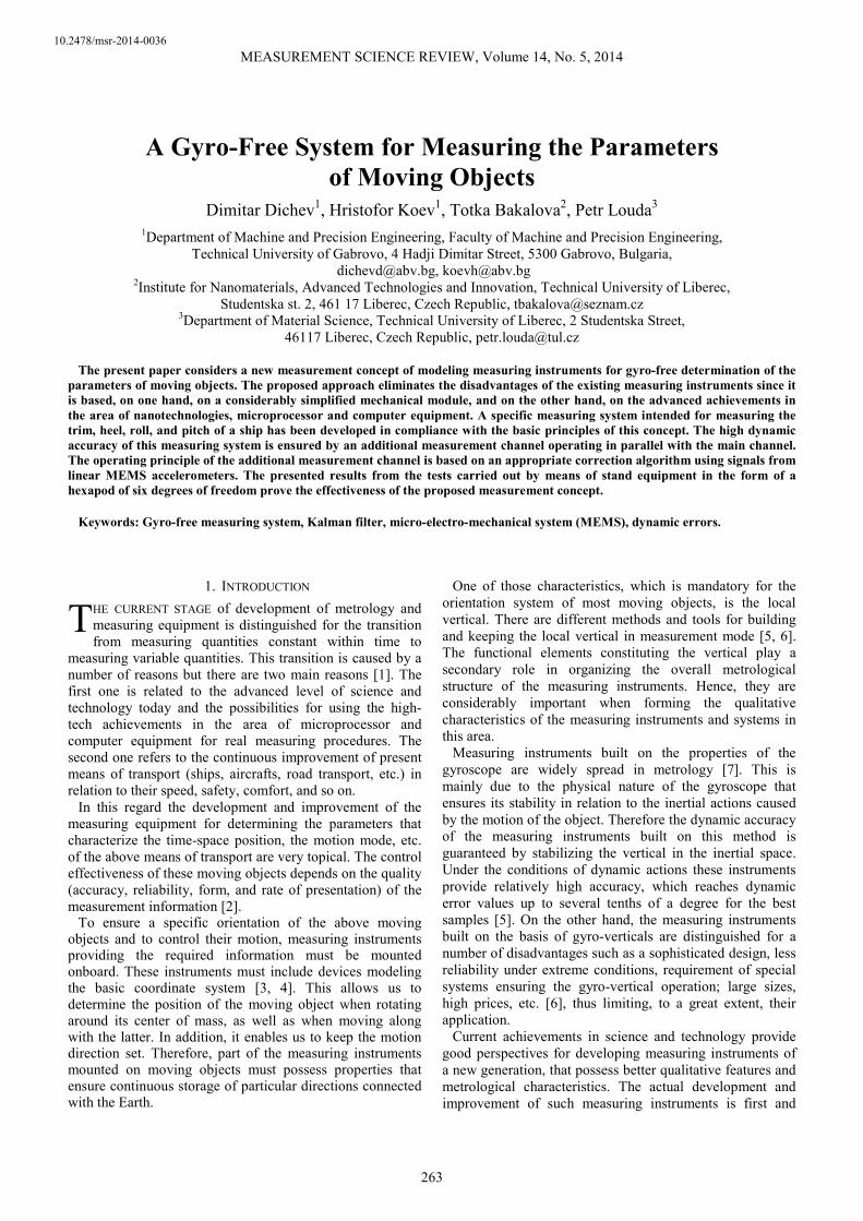
The block diagram illustrating the operating principle of
the measuring systems developed according to the concept
of the present approach is shown in Fig.1. In general, it
consists of a main measurement channel, an additional
channel, interfaces to connect with a computer, and program
modules for processing and presenting measurement
information.
The main channel is used for measuring the current values
of the angles determining the position of the moving object
in the basic coordinate system. It is based on the gyro-free
principle of vertical modeling and a very simplified design,
which results in considerably reducing the magnitude of the
instrumental errors.
However, this way of modeling the vertical leads to its
instability in the inertial space. Under inertial actions caused
by the motion and fluctuations of the object, this instability
determines the deviation of the elements modeling the
vertical from the actual direction of the vertical. All this
results in a dynamic error which in some cases can reach
inadmissibly high values [12]. Therefore, the proposed
concept envisages a procedure eliminating the current values
of the dynamic error from the measurement result.
The procedure related to the obtaining of the measurement
information required for determining the current values of
the dynamic error is implemented in the additional channel
(Fig.1.). The latter operates in parallel with the main
channel, which provides an opportunity to eliminate the
dynamic error from the measurement result in real time. The
structure of the additional channel and the type of devices
constituting it are specified on the basis of the selected
model for determining the current values of the dynamic
error and the algorithm for correcting the signal from the
main measurement channel.
Measuredquantity
Disturbancequantities
Basic measurement channel
Mecha-nicalmodule
A systemfor buildingthe vertical
meas
uri
ng
tran
sducer
s
Additional measure-ment channel
Meas. instr. n
Meas. instr. 2
Meas. instr. 1
Meas.chain
Output/result
Dat
a p
roce
ssin
g m
od
ule
Connect
ion
Inte
rfac
eC
onnec
tion
Inte
rfac
e
Computer
Use
r In
terf
ace
Fig.1. Block diagram illustrating the principle of modeling of measuring systems.
MEASUREMENT SCIENCE REVIEW, Volume 14, No. 5, 2014
265
3. A MEASURING SYSTEM FOR DETERMINING THE HEEL AND
TRIM OF A MOVING OBJECT
To illustrate the characteristics of the proposed concept, a
specific measuring system developed in compliance with the
principles of this concept is presented. The system is
designed for measuring the roll, pitch, heel, and trim of a
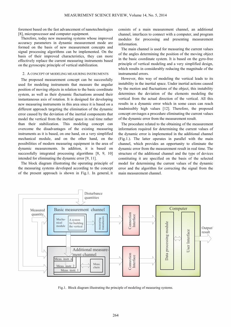
ship. Its block diagram is shown in Fig.2.
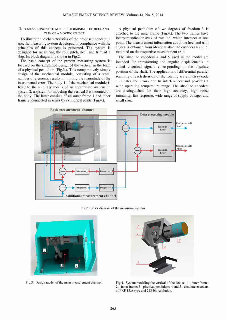
The basic concept of the present measuring system is
focused on the simplified design of the vertical in the form
of a physical pendulum (Fig.3.). This comparatively simple
design of the mechanical module, consisting of a small
number of elements, results in limiting the magnitude of the
instrumental error. The body 1 of the mechanical module is
fixed to the ship. By means of an appropriate suspension
system 2, a system for modeling the vertical 3 is mounted on
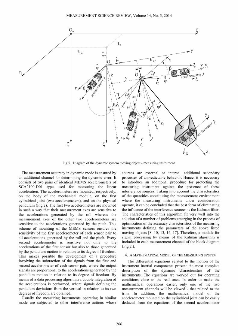
the body. The latter consists of an outer frame 1 and inner
frame 2, connected in series by cylindrical joints (Fig.4.).
A physical pendulum of two degrees of freedom 3 is
attached to the inner frame (Fig.4.). The two frames have
interperpendicular axes of rotation, which intersect at one
point. The measurement information about the heel and trim
angles is obtained from identical absolute encoders 4 and 5,
mounted on the respective measurement axis.
The absolute encoders 4 and 5 used in the model are
intended for transforming the angular displacements in
coded electrical signals corresponding to the absolute
position of the shaft. The application of differential parallel
scanning of each division of the rotating scale in Gray code
eliminates the errors due to interferences and provides a
wide operating temperature range. The absolute encoders
are distinguished for their high accuracy, high noise
immunity, fast response, wide range of supply voltage, and
small size.
Integrator_1 Integrator_2
Integrator_1 Integrator_2
Kalmanfilter
Kalmanfilter
Acce
lero
m .1
Acc
elero
m 2.
Acce
lero
m .3
Acc
eler
om
.4
Basic measurement channel
Additional measurement channel
Data processing module
PitchOutput/result
Roll
Output/result
Fig.2. Block diagram of the measuring system.
13
2
Fig.3. Design model of the main measurement channel.
1
2
3
4
5
Fig.4. System modeling the vertical of the device. 1 – outer frame;
2 – inner frame; 3 - physical pendulum; 4 and 5 - absolute encoders
of FKP 13.A type and 213-bit resolution.
MEASUREMENT SCIENCE REVIEW, Volume 14, No. 5, 2014
266
1
O
o
O
ζ
ξ
x
y
z
ψ
θ
αβ
η
ζ
ξ
ξ
ξ
ζ
ζ
η
η
o
o
o
η
θ
θ
θ.
ψ θ
.
ψθ
z
x
x1
x1
.
α
α
z
p
z
,x
p
θ
θ
1
1
yψ
.
z
y
y
C
y, p
ψ
ψ
β
.
z
z
1y
accelerometer_1
acce
lerom
eter_2
acce
ler o
met
er_
3
acce
lero
met
er_4
O
Fig.5. Diagram of the dynamic system moving object - measuring instrument.
The measurement accuracy in dynamic mode is ensured by
an additional channel for determining the dynamic error. It
consists of two pairs of identical MEMS accelerometers of
SCA2100-D01 type used for measuring the linear
acceleration. The accelerometers are mounted, respectively,
on the body of the mechanical module, on the first
cylindrical joint (two accelerometers), and on the physical
pendulum (Fig.2). The first two accelerometers are mounted
in such a way that their measurement axes are sensitive to
the accelerations generated by the roll whereas the
measurement axes of the other two accelerometers are
sensitive to the accelerations generated by the pitch. This
scheme of mounting of the MEMS sensors ensures the
sensitivity of the first accelerometer of each sensor pair to
all accelerations generated by the roll and the pitch. Every
second accelerometer is sensitive not only to the
accelerations of the first sensor but also to those generated
by the pendulum motion in relation to its degree of freedom.
This makes possible the development of a procedure
involving the subtraction of the signals from the first and
second accelerometer of each sensor pair, where the output
signals are proportional to the accelerations generated by the
pendulum motion in relation to its degree of freedom. By
means of a data processing algorithm a double integration of
the accelerations is performed, where signals defining the
pendulum deviations from the vertical in relation to its two
degrees of freedom are obtained.
Usually the measuring instruments operating in similar
mode are subjected to other interference actions whose
sources are external or internal additional secondary
processes of unpredictable behavior. Hence, it is necessary
to introduce an additional procedure for protecting the
measuring instrument against the presence of these
interference sources. Taking into account the characteristics
of the quantities constituting the measurement environment
where the measuring instruments under consideration
operate, it can be concluded that the best form of eliminating
the influence of the interference sources is the Kalman filter.
The characteristics of this algorithm fit very well into the
solution of a number of problems emerging in the process of
optimization of the accuracy characteristics of the measuring
instruments defining the parameters of the above listed
moving objects [8, 10, 13, 14, 17]. Therefore, a module for
signal processing by means of the Kalman algorithm is
included in each measurement channel of the block diagram
(Fig.2.).
4. A MATHEMATICAL MODEL OF THE MEASURING SYSTEM
The differential equations related to the motion of the
instrument inertial components present the most complete
description of the dynamic characteristics of the
instruments. The equations are worked out for operating
conditions close to the real ones. In order to make the
mathematical operations easier, only one of the two
measurement channels will be viewed - that related to the
trim. In addition, the mathematical model of the
accelerometer mounted on the cylindrical joint can be easily
deduced from the equations of the second accelerometer

MEASUREMENT SCIENCE REVIEW, Volume 14, No. 5, 2014
267
positioned on the instrument pendulum, due to which it will
not be taken into account when working out the differential
equations.
The differential equations are worked out on the basis of a
dynamic system shown in Fig.5. The motions of a ship are
defined as angular and linear fluctuations of a rigid body
around or along its center of gravity. The moving object (the
ship), to which the coordinate system Oxyz is connected,
changes its position randomly in relation to the supporting
system Ооξηζ. The measuring instrument is mounted on the
ship and its sensor (the physical pendulum) is connected to
the coordinate system Cx1y1z1. The suspension point О1 of
the instrument sensor coincides with the diametral plane of
the ship and its position with regard to the center of gravity
of the moving object О is defined by the z and y
coordinates. The position of the moving object in relation to
the supporting system Ооξηζ is set by the three coordinates
of its center of gravity О - ξо, ηо, ζо and the matrix ijaA =
(i,j=1,2,3) of the given angle cosines of the trim ψ and the
heel θ, defining the angular displacement between the axes
of the systems Ооξηζ and Оxyz. The mechanical system
consists of two bodies - a physical pendulum which is free
to rotate with regard to the coordinate axes О1x1 and О1y1,
and an accelerometer mounted in the center of gravity С of
the physical pendulum. The accelerometer inertial body of a
mass m2 stays at an equilibrium position in relation to the y1
coordinate by means of two horizontal springs of an elastic
constant с.
Therefore, the mechanical system has three degrees of
freedom and the generalized coordinates are, respectively,
α, β and y1. The α and β coordinates define the angular
displacement of the physical pendulum from the vertical in
relation to, respectively, О1y1 and О1x1 axes whereas y1
determines the relative motion of the inertial mass m2. By
means of the β coordinate the inertial component of the
dynamic error for the measurement channel under
consideration is defined. The latter determines the trim
values of a ship.
Upon working out the differential equations, the
Lagrangian method is used. Their matrix form is of the
following type:
,.....
....y..
.y...y..
.....
1
11
432
10
04
321
zRzPNzF
zEzSUyK
HyQGxM
DxCxBxJ
++++
++=++
+++++
++++
ψθ
βα
αβ
βα
&&
&&
&&&&
&&
(1)
where J is a 3×3 square matrix with the inertial
characteristics of the measuring system; T
1y&&&&&& βα=1x ; B – a 3×3 matrix with the kinematic
parameters of the system; T2
1
22y&&& βα=2x ; С – a
3×3 matrix with the damping parameters of the system; T
1y&&& βα=3x ; D – a column vector 3×1; М – a 3×3
matrix with the mass characteristics of the system;
T
1yβα=4x ; G - a column vector 3×1; Q – a 3×3
matrix with parameters characterizing the dynamics of the
measuring system; T
1111 y.y.y.y &&&&&& βα=0y ; H - a
column vector 3×1; K – a 3×3 matrix with parameters
characterizing the dynamics of the measuring system; T2
11
2
1
2
1 y.y.y.y &&& βα=y ; U - a column vector 3×1; S
– a 3×3 matrix with parameters characterizing the dynamics
of the ship; T
ooo ζξη &&&&&&=0z ; Е – a 3×2 matrix
characterizing the inertial parameters of the “ship-measuring
instrument” system; T
ψθ &&&&=1z ; N - a column vector
3×1.
The differential equations (1) are worked out by taking
into consideration the most complete and precise model of
quantities, defining the measurement environment.
Therefore, these differential equations describe in the most
appropriate way the properties and characteristics of the
measuring system. The availability of the mathematical
model (1) allows us to forecast the measurement results
when the system runs under different operating conditions,
as well as to optimize its structure and parameters so as to
satisfy the condition of a minimum error in the measurement
result.
Reducing the equations (1) to a simplified form by means
of linearization and inclusion of only small first-order
quantities provides a clear picture of the concept used in the
metrological procedure of the measuring system, i.e.
( )
( )
( )
( )
( ),.z.l.m2
1
y.cy.ky.m
;.l.z.mJ.l.m
.l.g.m.k.l.mJ
;.z.l.mJ.l.m
.l.g.m.k.l.mJ
02
11y12
1xo1
1
2
1x
1yo1
1
2
1y
1
1
1
1
1
ψξβ
ψξ
βββ
θη
ααα
β
α
&&&&&&
&&&
&&&&
&&&
&&&&
&&&
++−=
=++
+−−=
=+++
+−=
=+++
(2)
where kα, kβ and
1yk are damping factors along the three
generalized coordinates α, β and y1; l – the length of the
physical pendulum.
The third equation in (2) defines the link between the
readings of the accelerometer mounted on the physical
pendulum and the quantities entering at the input of the
instrument. A differential equation representing the motion
of the sensitive element of the second accelerometer can be
easily worked out from this equation, taking into account the
identical design characteristics of the two sensors and the
fact that this accelerometer is not sensitive to the motion of
the physical pendulum. Then the differential equation
sought will be:
( )ψξ &&&&&&& .z.m2
1y.cy.ky.m 02ppyp2 p
+−=++ , (3)

MEASUREMENT SCIENCE REVIEW, Volume 14, No. 5, 2014
268
where yp is the coordinate of the motion of the sensitive
element of the second accelerometer.
It can be seen in the third equation in (2) and (3) that the
difference between the readings of the two accelerometers
will be proportional to the function )t(β&& , by means of
which we can easily determine the quantity β(t) defining the
dynamic error. Namely this mathematical model serves as a
basis of the above proposed structure of the additional
channel and the processing algorithm using the signals from
two pairs of identical MEMS accelerometers.
5. EXPERIMENTS
To carry out the experiments, the required stand
equipment has been developed. It is a hexapod of six
degrees of freedom, which makes possible the reproduction
of the fluctuations of the ship in a form close to the real
operating conditions [15, 16, 18]. To ensure accuracy, the
equipment is calibrated and metrological traceability of its
unit to the length standard is provided. The equipment is
shown in Fig.6.
1
2
3
4
5
Fig.6. Stand equipment. 1 – operating platform; 2 - actuators; 3 –
immobile base; 4 – connection and control interface; 5 – computer.
Fig.7. illustrates the results from the investigation of the
dynamic accuracy of the measuring system in its two
operating modes. Within the first operating mode a Kalman
filter is not used. Unlike within the second operating mode a
module processing the measurement signals in compliance
with the Kalman algorithm is used. The curves in Fig.7.
show the dynamic errors for both operating modes in a
graphic format. The errors, respectively, without )t(deε and
with )t(kf
deε a module using a Kalman filter, are determined
by the expressions
)t()t()t( mrde ψψε −= ; (4)
)t()t()t( kf
mr
kf
de ψψε −= , (5)
where )t(mrψ and )t(kf
mrψ are the functions obtained as a
result of the measurement of the platform motion,
respectively, without and with a Kalman filter; ψ(t) – the
function defining the motion of the operating platform in
relation to the trim coordinate.
Errors )t(deε and )t(kf
deε are time functions since
according to (4) and (5) both the measurement result and the
referent quantity are dynamically changing processes.
Function ψ(t) defining the referent motion of the operating
platform along the trim coordinate is obtained as a result of
the constitutive motions of the platform along its six degrees
of freedom. The specific motion of the operating platform,
upon measuring of which errors )t(deε and )t(kf
deε in Fig 7.
are determined, is shown in Fig.8.
0 4 8 12 16 202.5− 10
3−×
1.175 103−
×
1.5 104−
×
1.475 103−
×
2.8 103−
×
Dynamic error
[rad]
Time [s]
ε(t)
de
ε(t)
de,
kf
ε (t)dekf
ε (t)de
Fig.7. Results from the investigation of the dynamic accuracy.
Time [s]
0 4 8 12 16 200.2−
0.0975−
5 103−
×
0.1075
0.21
Pitchψ(t)[rad]
Fig.8. Motion of the operating platform along the angular
coordinate ψ.
As it can be seen in Fig.7. (the red curve), the measuring
system is stable enough in relation to its dynamic accuracy
even without using the Kalman algorithm. In this case the
maximum values of the dynamic error are within a range of
0.15° - 0.16°. The experiments show that even under the
most severe conditions caused by the fluctuations of the ship
the error does not exceed 0.2° - 0.3°. The Kalman algorithm considerably improves the dynamic
accuracy of the measuring system, which is illustrated in
Fig.7. (the blue curve). It can be seen that the maximum
values of the dynamic error )t(kf
deε vary within a range of
0.05° - 0.07°.

MEASUREMENT SCIENCE REVIEW, Volume 14, No. 5, 2014
269
6. CONCLUSIONS
The proposed measurement concept is designed for
developing gyro-free measuring systems that determine the
parameters of moving objects. This modeling approach
overcomes the disadvantages of the existing measuring
instruments since it is based, on one hand, on a very
simplified mechanical module, and on the other hand, on the
advanced achievements in the area of nanotechnologies,
microprocessor and computer equipment.
The high dynamic accuracy of the proposed measuring
system is ensured by an additional measurement channel
operating in parallel with the main channel. The
metrological procedures in the additional channel are based
on an appropriate correction algorithm using signals from
linear MEMS accelerometers.
The experimental results confirm the effectiveness of the
proposed measurement concept in relation to the dynamic
accuracy of systems measuring moving objects. As a result
of the operation of the additional channel and the Kalman
algorithm the accuracy characteristics of the measuring
system under conditions of dynamic influences are
improved to a great extent. This can be implemented
without using expensive elements and stabilization systems.
ACKNOWLEDGMENT
The research reported in this paper was supported in part
by project LO1201 funded by the Ministry of Education,
Youth and Sports in the framework of the targeted support
of the "National Programme for Sustainability I" and the
OPR&DI project Centre for Nanomaterials, Advanced
Technologies and Innovation CZ.1.05/2.1.00/01.0005, as
well as by Project M1309/2014 financed by the Scientific
Research Fund at the Technical University of Gabrovo.
REFERENCES
[1] Dichev, D.A., Koev, H.C. (2012). Increase of dynamic
accurasy in measurement systems of parameters of
moving objects. In Metrology and Metrology
Assurance : XXII National Scientific Symposium.
Sazopol, Bulgaria, 57-64.
[2] Rivkin, S.S. (2002). Definition of Dynamic Errors of
Gyro-Instruments on a Moving Base. Moscow:
Azimut.
[3] Ivanov, Y.V. (2000). Autonomous sensors for heal,
trim and vertical displacements of underwater and
above-water objects. Sensors and Systems Magazine, 5
(1), 33-37.
[4] Pelpor, D.S. (1982). Orientation and Stabilization
Gyroscopic Systems. Moscow: Mashinostroene.
[5] Belyanin, L.N., Yakimova, Е.V. (2000). Vertical
accelerometer plotter. In Electronic and
Electromechanical Systems and Devices : XVI
Scientific Symposium. Tomsk, 148-153.
[6] Danilov, А.Т. (2001). A gyroscopic measuring system
for parameters of moving objects. Problems of Special
Machinebuilding Magazine, 4 (1), 178-181.
[7] Ivanov, Y.V. (2003). Inertial measurements in
dynamic mode by means of high-frequency physical
pendulums. Precision Engineering Magazine, 46 (9)
56-60.
[8] Albarbar, A., Badri, A., Sinha, J., Starr, A. (2009).
Performance evaluation of MEMS accelerometers.
Measurement, 42 (5), 790-795.
[9] Dichev, D., Koev, H., Louda, P. (2014). A measuring
system with an additional channel for eliminating the
dynamic error. Journal of Theoretical and Applied
Mechanics, 44 (1), 3-20.
[10] Zhu, R., Sun, D., Zhou, Z., Wang, D. (2007). A linear
fusion algorithm for attitude determination using low
cost MEMS-based sensors. Measurement, 40 (3), 322-
328.
[11] Dichev, D., Koev, H., Bakalova, T., Louda, P. (2014).
A model of the dynamic error as a measurement result
of instruments defining the parameters of moving
objects. Measurement Science Review, 14 (4), 183-
189.
[12] Sveshnikov, A.A., Rivkin, S.S. (1974). Probability
Methods in the Applied Gyroscope Theory. Moscow:
Nauka.
[13] Venkatesh, K. Arun, Mathivanan, N. (2013). CAN
network based longitudinal velocity measurement
using accelerometer and GPS receiver for automobiles.
Measurement Science Review, 13 (3), 115-121.
[14] Bohner, M., Wintz, N. (2013). The Kalman filter for
linear systems on time scales. Journal of Mathematical
Analysis and Applications, 406 (2), 419-436.
[15] Balchanowski, J. (2014). Some aspects of topology
and kinematics of a 3D of translational parallel
mechanism. International Journal of Applied
Mechanics and Engineering, 19 (1), 5-15.
[16] Kazakoff, A. (2012). Advances in engineering
software for lift transportation system. Journal of
Theoretical and Applied Mechanics, 42 (1), 3-22.
[17] Dichev, D., Koev, H., Bakalova, T., Louda, P. (2013).
An algorithm for improving the dynamic accuracy in
systems for measuring the parameters of moving
objects. International Journal of Engineering,
Business and Enterprise Applications, 5 (2), 1-9.
[18] Pendar, H., Mahnama, M., Zohoor, H. (2011).
Singularity analysis of parallel manipulators using
constraint plane method. Mechanism and Machine
Theory, 46 (1), 33-43.
Received April 23, 2014.
Accepted October 02, 2014.