a guide to working with electricity - … · cherie k. berry commissioner of labor osha state plan...
TRANSCRIPT

A Guide to
Working With Electricity
Bobby R. DavisSeries Editor
N.C. Department of LaborDivision of Occupational Safety and Health
1101 Mail Service CenterRaleigh, NC 27699-1101
Cherie K. BerryCommissioner of Labor

N.C. Department of LaborOccupational Safety and Health Program
Cherie K. BerryCommissioner of Labor
OSHA State Plan Designee
Allen McNeelyDeputy Commissioner for Safety and Health
Kevin BeauregardAssistant Deputy Commissioner for Safety and Health
Acknowledgments
This edition of A Guide to Working with Electricity has been updated to include material as prepared by the L. A.Weaver Company; U.S. Department of Labor, Occupational Safety and Health Administration; U.S. Department ofHealth and Human Services; and OSHNC personnel.
This guide is intended to be consistent with all existing OSHA standards; therefore, if an area is considered bythe reader to be inconsistent with a standard, then the OSHA standard should be followed.
To obtain additional copies of this book, or if you have questions about North Carolina occupational safety and health stan-dards or rules, please contact:
N.C. Department of LaborBureau of Education, Training and Technical Assistance
1101 Mail Service CenterRaleigh, NC 27699-1101
Phone: (919) 807-2875 or 1-800-NC-LABOR (1-800-625-2267)
____________________Additional sources of information are listed on the inside back cover of this book.
____________________
The projected cost of the OSHNC program for federal fiscal year 2003–2004 is $13,190,191. Federal funding provides approximately 39 percent ($5,162,000) of thistotal.
Printed 5/04

ContentsPart Page
Foreword . . . . . . . . . . . . . . . . . . . . . . . . . . . . . . . . . . . . . . . . . . .1iiv
1 Electrical Accidents . . . . . . . . . . . . . . . . . . . . . . . . . . . . . . .1ii1
2 Static Electricity . . . . . . . . . . . . . . . . . . . . . . . . . . . . . . . . . ii10
3 Ground-Fault Circuit Protection . . . . . . . . . . . . . . . . . . . . . . . . ii13
4 OSHA Standards Related to Lockout/Tagout or the Control of EnergyDuring Maintenance . . . . . . . . . . . . . . . . . . . . . . . . . . . . . . . ii23
5 Self-Inspection Checklist for the Electrician . . . . . . . . . . . . . . . . . . ii32
Terms and Definitions . . . . . . . . . . . . . . . . . . . . . . . . . . . . . . ii36
References . . . . . . . . . . . . . . . . . . . . . . . . . . . . . . . . . . . . ii38
iii

ForewordEveryone identifies electricity by what it does. Electricity gives us light, heat and power. It brings us
radio, television, motion pictures and the telephone. Modern industry could not exist without electricity.Electric motors run drills, milling machines, lathes and other tools. These tools mass-produce parts thatare quickly assembled on electrically operated conveyer belts. Powerful electric cranes lift huge loads.Electricity runs elevators and escalators in stores and office buildings. Electric signs advertise productsand businesses. Adding machines, computers and other electrical devices save office workers time andeffort.
Electricity is a very potent energy form. Used carelessly, it can deliver deadly shocks and injuries.During the past decade, the National Center for Health Statistics has reported about 1,000 accidentalelectrocutions annually in the United States. About a fourth of these deaths happen in industries or onfarms.
In North Carolina, state inspectors enforce the federal OSHA laws through a state plan approved bythe U.S. Department of Labor. The N.C. Department of Labor’s Division of Occupational Safety andHealth is charged with this mission. OSHNC enforces all current OSHA standards. It offers many educa-tional programs to the public and produces publications, including this guide, to help inform people abouttheir rights and responsibilities regarding OSHA.
When looking through this guide, please remember OSHA’s mission is greater than the enforcement ofregulations. An equally important goal is to help people find ways to create safe workplaces. This booklet,A Guide to Working with Electricity, like the other educational materials produced by the N.C. Departmentof Labor, can help.
Cherie K. BerryCommissioner of Labor
iv

1Electrical Accidents
The Effects of Electricity Upon the Human BodyElectricity is essential to modern life. Commonly used at both home and on the job, benefits offered by
electricity are realized every day through its use. Many workers in different occupations and industriesare exposed to electrical energy daily during the performance of their duties. Some employees work withelectricity directly, as is the case with engineers, electricians, electronic technicians and power line work-ers. Others, such as office workers and salespeople, work with it indirectly. Although you cannot taste orsmell electricity, inadvertent contact can surely make one aware of its presence. Dangers posed by elec-tricity are apparent, particularly when contact occurs accidentally or otherwise that can be felt and itsaffect noted on the human body. There are two kinds of electricity—static (stationary) and dynamic (mov-ing). Dynamic electricity is characterized by the flow of electrons through a conductor. As a source ofpower, electricity is accepted without much thought to the hazards encountered. Perhaps because it hasbecome such a familiar part of our surroundings, it often is not treated with the respect it deserves.
OSHA’s electrical standards address concerns that electricity has long been recognized as a seriousworkplace hazard, exposing employees to such dangers as electric shock, electrocution, burns, fires andexplosions. In 1992, the Bureau of Labor Statistics reported that 6,210 work-related deaths occurred inprivate sector workplaces having 11 or more workers. Approximately 6 percent of the fatalities, 347deaths, were the direct result of electrocutions at work. OSHA’s electrical standards help minimize thesepotential hazards by specifying safety aspects in the design and use of electrical equipment and systems.
To handle electricity safely, it is necessary to understand how it acts, how it can be directed, what haz-ards it presents, and how these hazards can be controlled. Operating an electric switch may be consideredin comparison to turning on a water faucet. Behind the faucet or switch there must be a source of wateror electricity, with something to transport it and with pressure to make it flow. In the case of water, thesource is a reservoir or pumping station; the transportation is through pipes; and the force to make it flowis pressure, provided by a pump. For electricity, the source is the power generating station; current trav-els through electric conductors in the form of wires; and pressure, measured in volts, is provided by a gen-erator.
When you turn on an electrical power tool or device, such as your circular saw or throw a circuit break-er, you allow current to flow from the generating source, through conductors (wiring), to the area ofdemand or load (i.e., equipment or lighting). A complete circuit is necessary for the flow of electricitythrough a conductor. A complete circuit is made up of a source of electricity, a conductor and a consumingdevice (load), such as a portable drill. The equation known as Ohm’s law (volts = current x resistance;or V = IR) shows the relationship between three factors. This relationship makes it possible to changethe qualities of an electrical current but keep an equivalent amount of power.
Resistance to the flow of electricity is measured in ohms and varies widely. It is determined by threefactors: the nature of the substance itself, the length and cross-sectional area (size) of the substance, andthe temperature of the substance. Some substances, such as metals, offer very little resistance to the flowof electric current and are called conductors. Other substances, such as porcelain, pottery and dry wood,offer such a high resistance that they can be used to prevent the flow of electric current and are calledinsulators. Dry wood has a high resistance, but when saturated with water its resistance drops to thepoint where it will readily conduct electricity. The same is true of human skin. When it is dry, skin has afairly high resistance to electric current; but when it is moist, there is a radical drop in resistance. Purewater is a poor conductor, but small amounts of impurities, such as salt and acid (both of which are con-tained in perspiration), make it a ready conductor. When water is present either in the environment or onthe skin, anyone working with electricity should exercise even more caution than they normally would.
1

Current Reaction
1 mA Perception level. Just a faint tingle.
5 mA Slight shock felt; not painful by disturbing.
6–25 mA (Women) Painful shock; muscular control is lost.
9–30 mA (Men) Called the freezing current or “let-go” range.
50–150 mA Extreme pain, respiratory arrest, severe muscular contractions.Individual cannot let go. Death is possible.
1,000–4,300 mA Ventricular fibrillation. (The rhythmic pumping action of the heart ceases.)Muscular contraction and nerve damage occur. Death is most likely.
10,000 mA Cardiac arrest, severe burns and probable death.
How Shocks OccurElectricity travels in closed circuits, and its normal route is through a conductor. Electric shock occurs
when the body becomes a part of the electric circuit. The current must enter the body at one point andleave at another. Electric shock normally occurs in one of three ways. The individual, while in contactwith the ground, must come in contact with both wires of the electric circuit, one wire of an energized cir-cuit and the ground, or a metallic part that has become “hot” by contact with an energized conductor.
The metal parts of electric tools and machines may become energized if there is a break in the insula-tion of the tool or machine wiring. The worker using these tools and machines is made less vulnerable toelectric shock when there is a low-resistance path from the metallic case of the tool or machine to theground. This is done through the use of an equipment grounding conductor, a low-resistance wire thatcauses the unwanted current to pass directly to the ground, thereby greatly reducing the amount of cur-rent passing through the body of the person in contact with the tool or machine. If the equipment ground-ing conductor has been properly installed, it has a low resistance to ground, and the worker is protected.
Controlling Electrical HazardsThe severity of the shock received when a person becomes a part of an electric circuit is affected by
three primary factors: the amount of current flowing through the body (measured in amperes), the path ofthe current through the body and the length of time the body is in the circuit. Other factors that mayaffect the severity of shock are the frequency of the current, the phase of the heart cycle when shockoccurs and the general health of the person.
The effects of electric shock depends upon the type of circuit, its voltage, resistance, current, pathwaythrough the body and duration of the contact. Effects can range from a barely perceptible tingle to imme-diate cardiac arrest. Although there are no absolute limits or even known values that show the exactinjury from any given current, table 1 shows the general relationship between the degree of injury andamount of current for a 60-cycle hand-to-foot path of one second’s duration of shock.
The table also illustrates that a difference of less than 100 milliamperes exists between a current thatis barely perceptible and one that can kill. Muscular contraction caused by stimulation may not allow thevictim to free himself or herself from the circuit, and the increased duration of exposure increases thedangers to the shock victim. For example, a current of 100 milliamperes for 3 seconds is equivalent to acurrent of 900 milliamperes applied for .03 seconds in causing ventricular fibrillation. The so-called lowvoltages can be extremely dangerous because, all other factors being equal, the degree of injury is propor-tional to the length of time the body is in the circuit. Low voltage does not imply low hazard! A severeshock can cause considerably more damage to the body than is visible. For example, a person may sufferinternal hemorrhages and destruction of tissues, nerves and muscles. In addition, shock is often only thebeginning in a chain of events. The final injury may well be from a fall, cuts or burns.
Table 1
Effects of Electric Current on Body
2
Electrical injuries may occur in various ways: direct contact with electrical energy, injuries that occurwhen electricity arcs (an arc is a flow of electrons through a gas, such as air) to a victim at ground poten-tial (supplying an alternative path to ground), flash burns from the heat generated by an electrical arc,and flame burns from the ignition of clothing or other combustible, nonelectrical materials. Direct contactand arcing injuries produce similar effects. Burns at the point of contact with electrical energy can becaused by arcing to the skin, heating at the point of contact by a high-resistance contact or higher voltagecurrents. Contact with a source of electrical energy can cause external as well as internal burns.Exposure to higher voltages will normally result in burns at the sites where the electrical current entersand exits the human body. High voltage contact burns may display only small superficial injury; however,the danger of these deep burns destroying tissue just beneath the skin exists. In addition, internal bloodvessels may clot, nerves in the area of the contact point may be damaged, and muscle contractions maycause skeletal fractures either directly or in association with falls from elevation. It is also possible tohave a low-voltage electrocution without visible marks to the body of the victim.
Flash burns and flame burns are actually thermal burns. In these situations, electrical current doesnot flow through the victim, and injuries are often confined to the skin. Contact with electrical currentcould cause a muscular contraction or a startle reaction that could be hazardous if it leads to a fall fromelevation (ladder, aerial bucket, etc.) or contact with dangerous equipment. The NEC describes high volt-age as greater than 600 volts AC. Most utilization circuits and equipment operate at voltages lower than600 volts, including common household circuits (110/120 volts); most overhead lighting systems used inindustry or office buildings and department stores; and much of the electrical machinery used in industry,such as conveyor systems, and manufacturing machinery such as weaving machines, paper rollingmachines or industrial pumps.
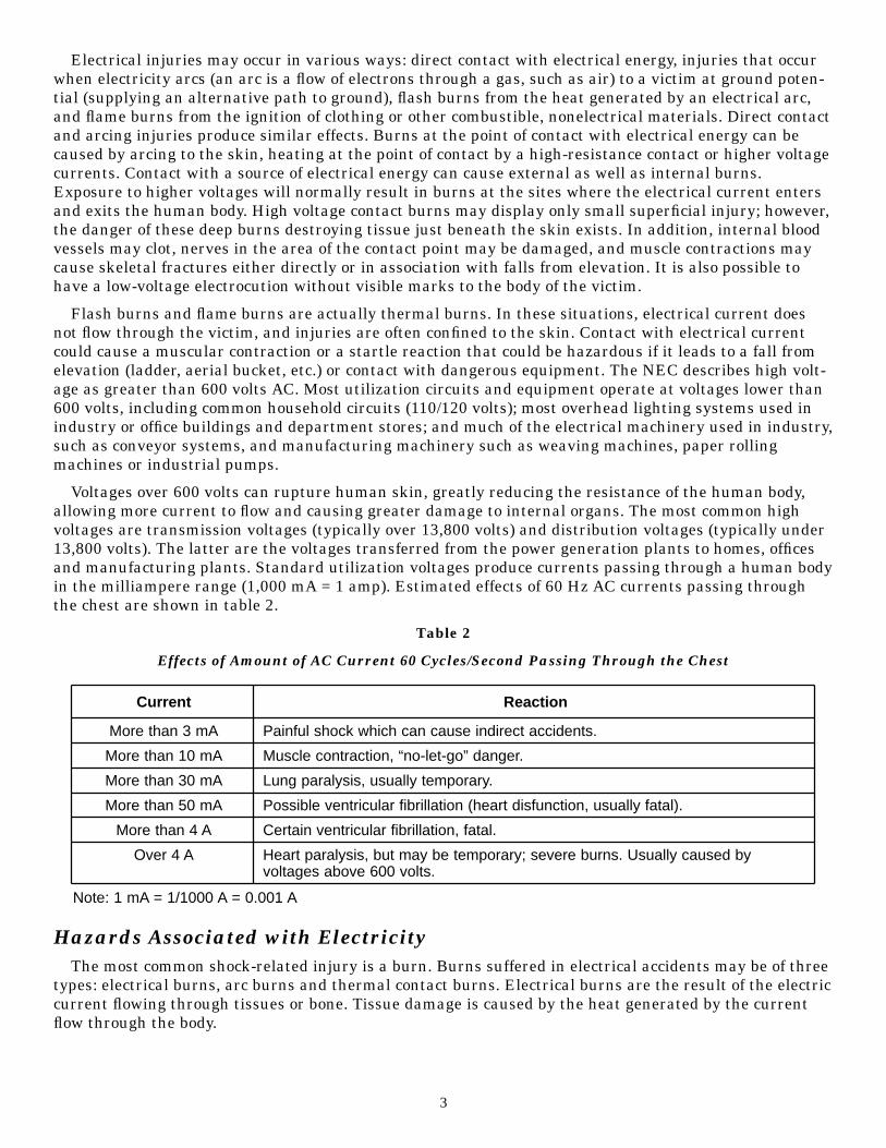
Voltages over 600 volts can rupture human skin, greatly reducing the resistance of the human body,allowing more current to flow and causing greater damage to internal organs. The most common highvoltages are transmission voltages (typically over 13,800 volts) and distribution voltages (typically under13,800 volts). The latter are the voltages transferred from the power generation plants to homes, officesand manufacturing plants. Standard utilization voltages produce currents passing through a human bodyin the milliampere range (1,000 mA = 1 amp). Estimated effects of 60 Hz AC currents passing throughthe chest are shown in table 2.
Table 2
Effects of Amount of AC Current 60 Cycles/Second Passing Through the Chest
Hazards Associated with ElectricityThe most common shock-related injury is a burn. Burns suffered in electrical accidents may be of three
types: electrical burns, arc burns and thermal contact burns. Electrical burns are the result of the electriccurrent flowing through tissues or bone. Tissue damage is caused by the heat generated by the currentflow through the body.
3
Current Reaction
More than 3 mA Painful shock which can cause indirect accidents.
More than 10 mA Muscle contraction, “no-let-go” danger.
More than 30 mA Lung paralysis, usually temporary.
More than 50 mA Possible ventricular fibrillation (heart disfunction, usually fatal).
More than 4 A Certain ventricular fibrillation, fatal.
Over 4 A Heart paralysis, but may be temporary; severe burns. Usually caused byvoltages above 600 volts.
Note: 1 mA = 1/1000 A = 0.001 A

Electrical burns are one of the most serious injuries you can receive and should be given immediateattention. Arc or flash burns, on the other hand, are the result of high temperatures near the body andare produced by an electric arc or explosion. They should also be attended to promptly. Finally, thermalcontact burns are those normally experienced when the skin comes in contact with hot surfaces of over-heated electric conductors, conduits or other energized equipment. Additionally, clothing may be ignitedin an electrical accident and a thermal burn will result. All three types of burns may be produced simul-taneously.
Electric shock can also cause injuries of an indirect or secondary nature in which involuntary musclereaction from the electric shock can cause bruises, bone fractures, and even death resulting from colli-sions or falls. In some cases, injuries caused by electric shock can be a contributory cause of delayed fatal-ities. In addition to shock and burn hazards, electricity poses other dangers. For example, when a shortcircuit occurs, the arcs can cause injury or start a fire. Extremely high-energy arcs can damage equip-ment, causing fragmented metal to fly in all directions. Even low-energy arcs can cause violent explosionsin atmospheres that contain flammable gases, vapors or combustible dusts. Electrical accidents appear tobe caused by a combination of three possible factors - unsafe equipment and/or installation, workplacesmade unsafe by the environment, and unsafe work practices. There are various ways of protecting peoplefrom the hazards caused by electricity. These include insulation, guarding, grounding, electrical protec-tive devices and safe work practices.
InsulationOne way to safeguard individuals from electrically energized wires and parts is through insulation. An
insulator is any material with high resistance to electric current. Some examples of insulators includeglass, mica, rubber and plastic. These are put on conductors to prevent shock, fires and short circuits.Before employees prepare to work with electric equipment, it is always a good idea for them to check theinsulation before making a connection to a power source to be sure there are no exposed wires. The insu-lation of flexible cords, such as extension cords, is particularly vulnerable to damage. The insulation thatcovers conductors is regulated by subpart S of the Safety and Health Standards for General Industry (29Code of Federal Regulations Part 1910.302, Design Safety Standards for Electrical Systems). Subpart Kcontains the Safety and Health Standards for the Construction Industry (29 Code of Federal RegulationsPart 1926.404, Installation Safety Requirements).
Subpart S generally requires that circuit conductors (the material through which current flows) beinsulated to prevent people from coming into accidental contact with the current. Also, the insulationshould be suitable for the voltage and existing conditions, such as temperature, moisture, oil, gasoline orcorrosive fumes. All these factors must be evaluated before the proper choice of insulation can be made.Conductors and cables are marked by the manufacturer to show the maximum voltage and AmericanWire Gage size, the type letter of the insulation, and the manufacturer’s name or trademark.
Insulation is often color coded. In general, insulated wires used as equipment grounding conductors areeither continuous green or green with yellow stripes. The grounded conductors that complete a circuit aregenerally covered with continuous white or natural gray-colored insulation. The ungrounded conductors,or “hot wires,” may be any color other than green, white or gray. They are often colored black or red.
GuardingLive parts of electric equipment operating at 50 volts or more must be guarded against accidental con-
tact. Guarding of live parts may be accomplished by:
• Location in a room, vault or similar enclosure accessible only to qualified persons;
• Use of permanent, substantial partitions or screens to exclude unqualified persons;
• Location on a suitable balcony, gallery or platform elevated and arranged to exclude unqualified per-sons; or
• Elevation of 8 feet (2.44 meters) or more above the floor.
4

Entrances to rooms and other guarded locations containing exposed lives parts must be marked withconspicuous warning signs forbidding unqualified persons to enter. Indoor electric wiring more than 600volts and that is open to unqualified persons must be made with metal-enclosed equipment or enclosed ina vault or area controlled by a lock. In addition, equipment must be marked with appropriate cautionsigns.
GroundingGrounding is another method of protecting employees from electric shock; however, it is normally a sec-
ondary protective measure. The term “ground” refers to a conductive body, usually the earth, and meansa conductive connection, whether intentional or accidental, by which an electric circuit or equipment isconnected to earth or the ground plane. By grounding a tool or electrical system, a low-resistance path tothe earth is intentionally created. When properly done, this path offers sufficiently low resistance and hassufficient current carrying capacity to prevent the buildup of voltages that may result in a personnel haz-ard. See figure 1. This does not guarantee that no one will receive a shock, be injured or be killed. It will,however, substantially reduce the possibility of such accidents, especially when used in combination withother safety measures discussed in this booklet.
Figure 1
System and Equipment Grounding
There are two kinds of grounds required by Design Safety Standards for Electrical Systems (SubpartS). One of these is called the “service or system ground.” In this instance, one wire—called “the neutralconductor” or “grounded conductor”—is grounded. In an ordinary low-voltage circuit, the white (or gray)wire is grounded at the generator or transformer and again at the service entrance of the building. Thistype of ground is primarily designed to protect machines, tools and insulation against damage.
5
TransformerSecondary
Primary
GroundedConducted orNeutral
SystemGrounding
Equipment Grounding
EquipmentGroundingConductor
Electrical Symbolfor Ground
ServiceEntrance
Most metallic raceways, cable sheaths andcable armor that are continuous and utilizeproper fittings may serve as the equipmentgrounding conductor. A separate groundingconductor is needed when plastic conduit,non-metallic sheathed cable or other wiringmethods are used that are not approvedas grounding methods.

To offer enhanced protection to the workers themselves, an additional ground, called the “equipmentground,” must be furnished by providing another path from the tool or machine through which the currentcan flow to the ground. This additional ground safeguards the electric equipment operator in the eventthat a malfunction causes the metal frame of the tool to become accidentally energized. The resultingheavy surge of current will then activate the circuit protection devices and open the circuit. See figures 2aand 2b.
Figure 2a
Cord- and Plug-Connected Equipment Without a Grounding Conductor
Figure 2b
Cord- and Plug-Connected Equipment With a Grounding Conductor
6
Source of SupplyService Entrance
Bonded
A Short Circuit Insidethe Drill will Energize
the Case
Source of SupplyService Entrance
BondedEquipment Grounding
Conductor
Short CircuitInside Drill

Electrocutions From Contact With High Voltage Transmission Lines
Anyone who works in the vicinity of electrical power lines should be aware of the consequences of con-tacting energized lines. Anyone working on or around electrically energized conductors should:
1. Ensure adequate clearance between power lines and cranes, booms, measuring rods, boat masts, irri-gation pipes, radio and TV antennas, or any other metal object or structure.
2. Consider all overhead wires to be energized unless they have been visibly grounded and tested.
3. Designate a person to observe clearance of equipment and give timely warning of all operationswhere it is difficult for the operator to observe the required clearance.
4. Use nonmetallic ladders, insulated tools, nonconductive equipment and appropriate personal protec-tive equipment.
5. Never depend solely on cage-type boom guards, insulating links or proximity devices to ensurerequired distance between a crane and power lines.
6. Ensure that all electrical work safety practices and procedures are thoroughly reviewed and dis-cussed prior to beginning a job.
7. Instruct new workers and retrain others who work with energized conductors and/or equipment,regardless of voltage level (one-tenth ampere flowing through the human body for only two seconds canbe fatal).
8. Use the buddy system with at least one member of each pair of workers trained in basic first aid andcardiopulmonary resuscitation (CPR).
9. Until the current has been cleared, refrain from touching the victim of an electrocution or the electri-cal apparatus that caused the injury, or use appropriate electrical protective equipment to remove the vic-tim.
In addition to the preceding measures recommended for preventing electric shock and electrocutions,one should conduct a thorough and frequent review of all applicable Occupational Safety and Health Actstandards.
Electrocutions From the Use of Portable Metal Ladders Near Overhead Power Lines
Workers using portable metal ladders, including aluminum ladders, near overhead power lines are atrisk of electrocution. From 1980 through 1985, the contact of metal ladders with overhead power linesaccounted for 4 percent of all work-related electrocutions in the United States. The lack of compliancewith existing OSHA regulations regarding portable metal ladders suggests that many employers areunaware of the regulations, misinterpret the requirements or fail to inform their workers about the dan-gers of using metal ladders near power lines.
OSHA requirements prohibit the use of portable metal or conductive ladders for electrical work or inlocations where they may contact electrical conductors. Nonconductive ladders, such as those made ofwood or fiberglass, should be used instead.
If portable metal ladders are used in the vicinity of energized power lines, all employers and workersshould strictly adhere to OSHA standards requiring the proper balancing and securing of ladders and main-tenance of safe working distances to avoid contact with electrical conductors. To ensure proper protection foranyone working near electrical power lines, arrangements should be made with the power company to de-energize the lines or to cover the lines with insulating line hoses or blankets.
Employers should fully inform workers about the hazards of using portable metal ladders near ener-gized power lines. Fatalities may be prevented by prompt emergency medical care. Workers should betrained in emergency medical procedures such as CPR.
7
Preventing Fatalities of Workers Who Contact Electrical EnergyNational Institute for Occupational Safety and Health recommendations for helping to save the lives of
workers who contact electrical energy call for the use of a buddy system. That system ensures that no oneworks alone with electrical energy and makes first aid and CPR immediately available.
Incidents studied by NIOSH revealed that electrocution victims can be revived if immediate CPR ordefibrillation is provided. While immediate defibrillation would be ideal, CPR given within approximatelyfour minutes of the electrocution, followed by advanced cardiac life support (ACLS) measures withinapproximately eight minutes, can be lifesaving.
An estimated 700 occupational electrocutions occur each year. Therefore, a primary goal of occupation-al safety programs is to prevent workers from contacting electrical energy. Effective means of preventioninclude safe work practices, job training, proper tools, protective equipment and lockout/tagout proce-dures. A secondary goal is the ensuring of appropriate emergency medical care to workers who contactelectrical energy.
The National Electrical Code divides voltages into two categories: greater than 600 volts (high voltage)and less than or equal to 600 volts (low voltage). Momentary contact with low voltages produces no ther-mal injury but may cause ventricular fibrillation (very rapid, ineffective heartbeat).
In contacts with high voltage, massive current flows may stop the heart completely. When the circuitbreaks, the heart may start beating normally. Supporting respiration by immediate mouth-to-mouth tech-niques may be required, even if heartbeat and pulse are present. If extensive burns are present, deathmay result from subsequent complications.
Standards and Guidelines for Medical Care for Workers Who Contact Electrical Energy
The National Conference on CPR and ECC [Emergency Cardiac Care] produced revised standards andguidelines for medical care for workers who contact electrical energy. There are two parts: CPR andACLS. A lay person can be trained in CPR to support circulation and ventilation of the victim of cardiac orrespiratory arrest, until ACLS (provided by medical professionals using special equipment) can restore nor-mal heart and ventilatory action.
Speed is critical to resuscitation. The highest success rate has been achieved with patients for whomCPR followed cardiac arrest within approximately four minutes and ACLS was begun within approxi-mately eight minutes of the arrest. CPR often must be initiated immediately by lay individuals at thescene of the incident. CPR skills can be gained in four-hour courses taught by the American HeartAssociation, American Red Cross and other agencies.
Recommendations Regarding Employees Who Work Around or With Electrical Energy
For employees who work around or with electrical energy, the following safeguards are recommended:
1. Prevention. Prevention must be the primary goal of any occupational safety program. Since contactwith electrical energy occurs even in facilities that promote safety, safety programs should provide for anappropriate emergency medical response.
2. Safe Work Practices. No one who works with electrical energy should work alone, and in manyinstances, a buddy system should be established. It may be advisable to have both members of the buddysystem trained in CPR, as one cannot predict who will contact electrical energy.
Every individual who works with or around electrical energy should be familiar with emergency proce-dures. This should include knowing how to de-energize the electrical system before rescuing or beginningresuscitation on a worker who remains in contact with an electrical energy source.
All workers exposed to electrical hazards should be made aware that even low voltage circuits can befatal and that prompt emergency medical care can be lifesaving.
8

3. CPR and ACLS Procedures. CPR and first aid should be immediately available at every worksite.This capability is necessary to provide prompt (within four minutes) care for victims of cardiac or respira-tory arrest from any cause.
Employers may contact the local office of the American Heart Association, the American Red Cross, orequivalent groups or agencies to set up a course on CPR for employees.
Provision should be made for the availability of ACLS at each worksite. ACLS should be availablewithin eight minutes. ACLS may be available through an ambulance staffed with paramedics. Signsshould be placed on or near telephones to provide the correct emergency number for the area. Workersshould be educated regarding the information to give when a call is made. For large facilities, a pre-arranged place should be established where company personnel are to meet paramedics in an emergency.
9

2Static Electricity
The material universe is composed of atoms, and the outermost parts of atoms are composed of elec-trons. There are many ways in which an outer electron may be detached from an atom. Detached elec-trons appear in electrical occurrences—static electricity. Static electricity is extremely commonplace, aselectrons can be detached and transferred from surface atoms through mere contact and separation ofmaterial bodies. Fortunately, however, in the majority of cases, contact is made only at a few points, andas there is often little resistance to the return of electrons at the moment the contacting bodies are sepa-rated, the external effects are feeble and pass unnoticed.
In certain materials, notably metals, electrons can move from atom to atom with considerable naturalfreedom. This makes these materials good conductors of electricity. Other materials, such as glass, stone,rubber, plastics and textiles, have molecular structures that offer great resistance to the flow of electrici-ty, and, consequently, these are called nonconductors or insulators. Materials that are neither good con-ductors nor good insulators are sometimes called semiconductors. Moderate opposition to the flow of elec-tricity is expressed in units called ohms. A larger unit, the megohm (1,000,000 ohms), is generallyemployed in high-resistance measurements.
When dissimilar materials are pressed together, free electrons from the surface structure of one mater-ial may shift across the contact, or interface, to the other. If the materials are separated, the new distrib-ution of electrical entities probably will persist if one or both of the materials are conductors. The extentand direction of the electrical shift between contacting surfaces depend largely upon the nature of thematerials and are usually in accord with their position in tabulations known as tribo-electric series. Theobject that acquires extra electrons is said to have a negative (–) charge and the one that loses electrons,a positive (+) charge. Considered minutely, a normal atom or molecule that gains an electron is a negativeion, and one that loses an electron is a positive ion. The transfer of electrons or ions by contact and sepa-ration is often facilitated by rubbing and friction, whence the name “friction electricity.” Positive and neg-ative charges (quantities) of electricity produced and kept apart by nonconductors are virtually at rest:that is, they are static. Owing to their difference of potential, they are acted upon by a force that tends tounite them. This reunion will take place instantly if a low-resistance circuit is provided. It will occur inany event because there are no perfect insulators. Charges acquire voltage or potential in proportion tothe amount of work or energy required to separate them. Stress in the electrical field or region aroundcharged bodies is seen not only in the attraction of opposite charges but also in the repulsion of charges oflike kind. As this effect is elemental, static charges in the aggregate are self-repellent and, thus, normallyreside only on the external surfaces of electrified objects.
The quantities of electricity dealt with in electrostatics are generally so small that it is convenient toemploy the terms picofarad (10–12 farad), picocoulomb (10–12 coulomb) and millijoule (10–3 joule). Staticelectric potentials are conveniently expressed either in volts or kilovolts (103 volts).
General Control MethodsHumidification
The addition of water vapor does not make air electrically conductive; however, the leakage resistanceof most substances (with the exception of a few waxes and resins) decreases greatly as the atmospherichumidity increases, owing to absorption of moisture from the air.
Humidification has long been employed in industrial processes for controlling static. This is particular-ly true of the textile industry, where attraction and repulsion of charged fibers and strands can affect thequality of the manufactured products. Control of humidity has frequently been proposed as a means ofeliminating static electricity in hospital operating suites.
To be effective in reducing static to a nonhazardous level, the relative humidity must be at least 60 per-cent and probably considerably higher owing to the present extensive use of nonconductive rubber. In the
10

textile industry reference is made to a standard atmosphere of 65 percent relative humidity and 70degrees Fahrenheit, at which practically no static will develop.
Since several hours may be necessary for materials to come to moisture equilibrium in changed atmos-phere, safety from static cannot be ensured unless proper humidity has been maintained for a long periodbefore activities begin. Probably the system should be run continuously. No enduring protection is afford-ed when the system is shut down for repairs or servicing or when its operating schedule is irregular.
Bonding and Grounding
Static sparking does not occur between objects at the same potential. Bonding is the term used to indi-cate the equalization of potential between two conductive bodies by connecting them together by means ofa conductive wire. Objects bonded together have a zero potential difference with each other but may stillretain a charge and have a potential difference with respect to adjacent unbonded objects.
Grounding is the connecting of a conductive body to the earth by a conductive wire. It is assumed thatthe potential of the ground is invariant. Therefore, objects connected to the ground by conductive wireswill have zero potential difference with respect to each other. When a charged object is grounded, it issaid to have a positive potential if electrons flow from the object to the ground and a negative potential ifelectrons flow from the ground to the object.
Bonding and grounding are usually effective if the objects so treated are good conductors. They areeffective as a control measure for semiconductors if the rate of charge accumulation is less than the rateof charge dissipation. A rapid neutralization of a poor conductor will probably not occur, or may occuronly at the area of contact of the ground wire and the object.
A bond or ground wire should have adequate mechanical strength, be corrosion resistant and have thenecessary flexibility for the service intended. Size No. 8 or No. 10 AWG copper wire is about the minimumsuitable size. Permanent connections should be welded or brazed. Temporary connections may be madeusing tight battery clamps or screw clamps. Any ground wire suitable for power circuits is more than ade-quate for static grounding; however, it is not wise to use the same ground for the two purposes simultane-ously. Insulated or noninsulated wires may be used for bonding or grounding. If insulated wire is used,more frequent tests for electrical continuity should be made.
Ionization
Ionization of the air in immediate contact with a charged body provides a conducting path throughwhich the charge may dissipate. Methods by which such ionization can be accomplished form the basis fora variety of control measures.
Static charges on a conducting surface are free to flow and, due to repulsion between like charges, tendto distribute themselves as uniformly as possible. On a spherical body, this distribution is uniform. If theobject is not spherical, the charge will concentrate on the surface with the least radius of curvature. If thesurface has an almost zero radius of curvature such as the needle point, the charge concentration on thissurface can become great enough to cause ionization of the surrounding air.
A static comb is a metal bar equipped with rows of needle points or a metal wire wrapped with metallictinsel. When a grounded static comb is brought close to an insulated charged object, ionization of the airsurrounding the points of the comb will provide a conductive path over which the charge on the object dis-sipates to the ground.
The ionizing charge on a simple static comb is induced by the close proximity of a charged object.Such an induced charge is not constant in intensity nor uniform along the length of the bar. In order toimprove the efficiency of such static control bars, a constant high voltage may be impressed upon the barby some outside source such as an AC transformer. The points on these high voltage electrostatic elimi-nators are arranged to act as capacitors. The bar itself is grounded. Figure 3 illustrates a high voltagestatic eliminator.
11

Figure 3
High Voltage Static Eliminator
12
250V
AC Transformer
10,000–15,000V
Point
Insulator
Ground
3Ground-Fault Circuit Protection
Circuit Protection DevicesCircuit protection devices are designed to automatically limit or shut off the flow of electricity in the
event of a ground-fault, overload or short circuit in the wiring system. Fuses, circuit breakers andground-fault circuit interrupters are three well-known examples of such devices.
Fuses and circuit-breakers are over-current devices that are placed in circuits to monitor the amount ofcurrent that the circuit will carry. They automatically open or break the circuit when the amount of cur-rent flow becomes excessive and therefore unsafe. Fuses are designed to melt when too much currentflows through them. Circuit breakers, on the other hand, are designed to trip open the circuit by electro-mechanical means. Fuses and circuit breakers are intended primarily for the protection of conductors andequipment. They prevent overheating of wires and components that might otherwise create hazards foroperators. They also open the circuit under certain hazardous ground-fault conditions.
The ground-fault circuit interrupter, or GFCI, is designed to shut off electric power within as little asone-fortieth of a second. It works by comparing the amount of current going to electric equipment againstthe amount of current returning from the equipment along the circuit conductors. If the current differ-ence exceeds 6 milliamperes, the GFCI interrupts the current quickly enough to prevent electrocution.The GFCI is used in high-risk areas such as wet locations and construction sites.
The GFCI contains a special sensor that monitors the strength of the magnetic field around each wire inthe circuit when current is flowing. The magnetic field around a wire is directly proportional to the amountof current flow, thus the circuitry can accurately translate the magnetic information into current flow.
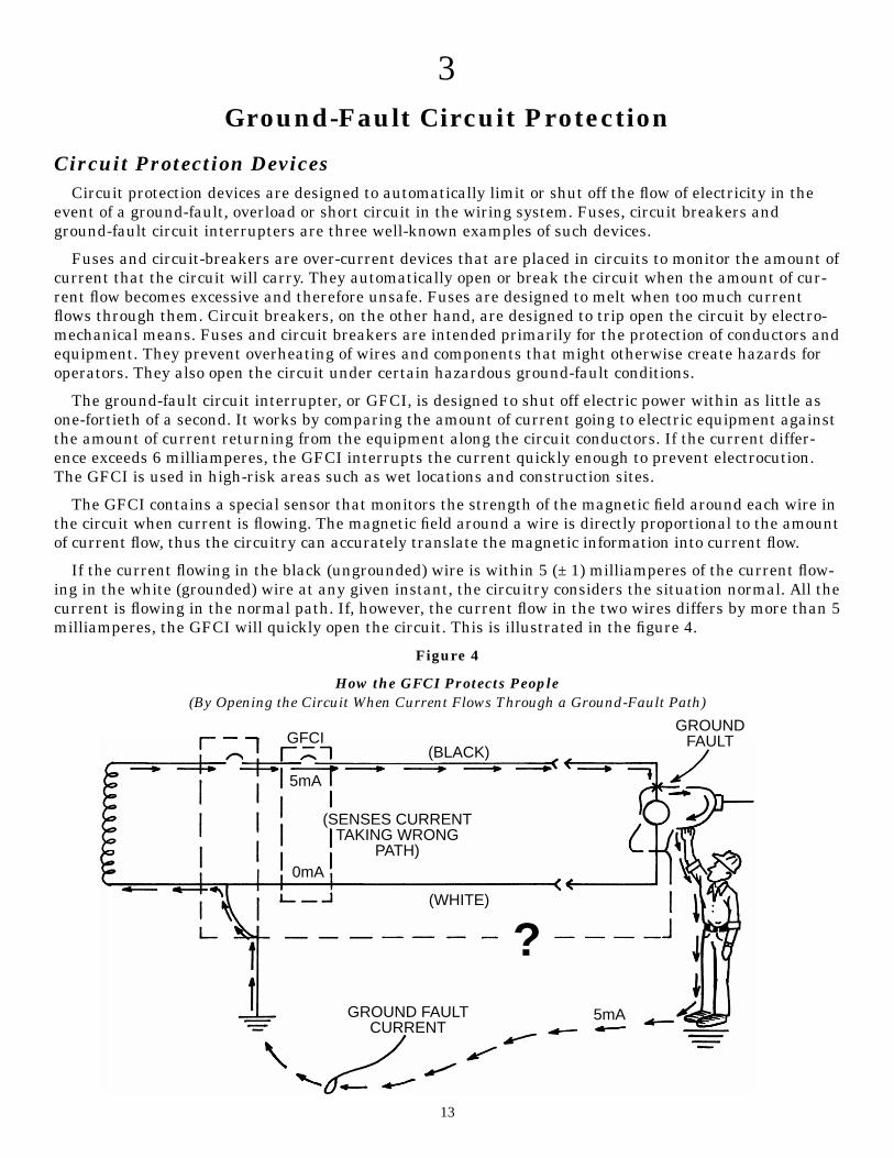
If the current flowing in the black (ungrounded) wire is within 5 (± 1) milliamperes of the current flow-ing in the white (grounded) wire at any given instant, the circuitry considers the situation normal. All thecurrent is flowing in the normal path. If, however, the current flow in the two wires differs by more than 5milliamperes, the GFCI will quickly open the circuit. This is illustrated in the figure 4.
Figure 4
How the GFCI Protects People(By Opening the Circuit When Current Flows Through a Ground-Fault Path)
13
GFCI
5mA
0mA
(BLACK)
(WHITE)
GROUNDFAULT
5mAGROUND FAULTCURRENT
?
(SENSES CURRENTTAKING WRONG
PATH)

Note that the GFCI will open the circuit if 5 milliamperes or more of current returns to the serviceentrance by any path other than the intended white (grounded) conductor. If the equipment groundingconductor is properly installed and maintained, this will happen as soon as the faulty tool is plugged in. Ifby chance this grounding conductor is not intact and of low-impedance, the GFCI may not trip out until aperson provides a path. In this case, the person will receive a shock, but the GFCI should trip out soquickly that the shock will not be harmful.
Safe Work PracticesEmployees and others working with electric equipment need to use safe work practices. These include
deenergizing electric equipment before inspecting or making repairs, using electric tools that are in goodrepair, using good judgment when working near energized lines, and using appropriate protective equip-ment. Electrical safety-related work practice requirements are contained in Subpart S of 29 CFR Part1910, in sections 1910.331–1910.335.
TrainingTo ensure that they use safe work practices, employees must be aware of the electrical hazards to
which they will be exposed. Employees must be trained in safety-related work practices as well as anyother procedures necessary for safety from electrical hazards.
Polarity of Connections• No grounded conductor may be attached to any terminal or lead so as to reverse designated polarity.
• A grounding terminal or grounding-type device on a receptacle, cord connector or attachment plugmay not be used for purposes other than grounding.
The above two subparagraphs dealing with polarity of connections and use of grounding terminals anddevices address one potentially dangerous aspect of alternating current: many pieces of equipment willoperate properly even though the supply wires are not connected in the order designated by design or themanufacturer. Improper connection of these conductors is most prevalent on the smaller branch circuittypically associated with standard 120 volt receptacle outlets, lighting fixtures, and cord- and plug-con-nected equipment. When plugs, receptacles and connectors are used in an electrical branch circuit, cor-rect polarity between the ungrounded (hot) conductor, the grounded (neutral) conductor and the ground-ing conductor must be maintained.
Reversed polarity is a condition when the identified circuit conductor (the grounded conductor or neu-tral) is incorrectly connected to the ungrounded or hot terminal of a plug, receptacle or other type of con-nector. Correct polarity is achieved when the grounded conductor is connected to the correspondinggrounded terminal and the ungrounded conductor is connected to the corresponding ungrounded termi-nal. The reverse of the designated polarity is prohibited. Figure 5 illustrates a duplex receptacle correctlywired. Terminals are designated and identified to avoid confusion. An easy way to remember the correctpolarity is “white to light”—the white (grounded) wire should be connected to the light or nickel-coloredterminal; “black to brass”—the black or multi-colored (ungrounded) wire should be connected to the brassterminal; and “green to green”—the green or bare (grounding) wire should be connected to the greenhexagonal head terminal screw.
14

Figure 5
Duplex Receptacle Correctly Wired to Designated Terminals
Deenergizing Electrical Equipment. The accidental or unexpected sudden starting of electricalequipment can cause severe injury or death. Before any inspections or repairs are made—even on low-voltage circuits—the current must be turned off at the switchbox and the switch padlocked in the “off”position. At the same time, the switch or controls of the machine or other equipment being locked out ofservice must be securely tagged to show which equipment or circuits are being worked on.
Maintenance employees should be qualified electricians who have been well instructed in lockout pro-cedures. No two locks should be alike; each key should fit only one lock, and only one key should be issuedto each maintenance employee. If more than one employee is repairing a piece of equipment, each shouldlock out the switch with his or her own lock and never permit anyone else to remove it. The maintenanceworker should at all times be certain that he or she is not exposing other employees to danger.
Overhead LinesIf work is to be performed near overhead power lines, the lines must be deenergized and grounded by
the owner or operator of the lines, or other protective measures must be provided before work is started.Protective measures (such as guarding or insulating the lines) must be designed to prevent employeesfrom contacting the lines.
Unqualified employees and mechanical equipment must stay at least 10 feet (3.05 meters) away fromoverhead power lines. If the voltage is more than 50,000 volts, the clearance must be increased by 4 inch-es (10 centimeters) for each additional 10,000 volts.
When mechanical equipment is being operated near overhead lines, employees standing on the groundmay not contact the equipment unless it is located so that the required clearance cannot be violated evenat the maximum reach of the equipment.
Protective Equipment. Employees whose occupations require them to work directly with electricitymust use the personal protective equipment required for the jobs they perform. This equipment may consistof rubber insulating gloves, hoods, sleeves, matting, blankets, line hose and industrial protective helmets.
15
GroundedContactOpening
WhiteWire
Nickel or LightColored Terminals
Green or BareGroundingConductor
Green Hexagonal HeadTerminal Screw
UngroundedContactOpening
BlackWire
GroundingContactOpening
Brass-coloredTerminals

Tools. To maximize his or her own safety, an employee should always use tools that work properly.Tools must be inspected before use, and those found questionable, removed from service and properlytagged. Tools and other equipment should be regularly maintained. Inadequate maintenance can causeequipment to deteriorate, resulting in an unsafe condition. Tools that are used by employees to handleenergized conductors must be designed and constructed to withstand the voltages and stresses to whichthey are exposed.
Good Judgment. Perhaps the single most successful defense against electrical accidents is the contin-uous exercising of good judgment or common sense. All employees should be thoroughly familiar with thesafety procedures for their particular jobs. When work is performed on electrical equipment, for example,some basic procedures are:
1. Have the equipment deenergized.
2. Ensure that the equipment remains deenergized by using some type of lockout and tag procedure.
3. Use insulating protective equipment.
4. Keep a safe distance from energized parts.
Protection is generally available as a GFCI/circuit breaker or GFCI receptacle. The breaker has aground fault sensing circuit breaker body. The same breaker or interrupting mechanism is used for bothground faults and overloads. GFCI receptacles are located at the point of use; the receptacle opens thecircuit.
Insulation and Grounding DeficienciesInsulation and grounding are two recognized means of preventing injury during electrical equipment
operation. Conductor insulation may be provided by placing nonconductive material such as plasticaround the conductor. Grounding may be achieved through the use of a direct connection to a knownground such as a metal cold water pipe.
Consider, for example, the metal housing or enclosure around a motor or the metal box in which electri-cal switches, circuit breakers and controls are placed. Such enclosures protect the equipment from dirtand moisture and prevent accidental contact with exposed wiring; however, there is a hazard associatedwith housings and enclosures. A malfunction within the equipment—such as deteriorated insulation—may create an electric shock hazard. Many metal enclosures are connected to a ground to eliminate thehazard. If an energized wire contacts a grounded enclosure, a ground fault results, which normally willtrip a circuit breaker, blow a fuse or trip a GFCI. Metal enclosures and containers are usually groundedby connecting them with a wire going to the ground. This wire is called an equipment grounding conduc-tor. Most portable electric tools and appliances are grounded by this means. There is one disadvantage togrounding: a break in the grounding system may occur without the user’s knowledge, thus producing anunsuspected hazard.
Insulation may be damaged by hard usage on the job or by aging. If this damage causes the conductorsto become exposed, the hazards of shocks, burns, and fire will exist. Double insulation may be used asadditional protection on the live parts of a tool, but double insulation does not provide protection againstdefective cords and plugs or against heavy moisture conditions.
The use of a ground-fault circuit interrupter is one method used to overcome grounding and insulationdeficiencies.
GFCI Operation PrincipleIn most cases, insulation and grounding are used to prevent injury from electrical wiring systems or
equipment. However, there are instances when these recognized methods do not provide the degree ofprotection required. To help appreciate this, let’s consider a few examples of where ground fault circuitinterrupters would provide additional protection.
16

Many portable hand tools, such as electric drills, are now manufactured with non-metallic cases. Ifapproved, we refer to such tools as double insulated. Although this design method assists in reducing therisk from grounding deficiencies, a shock hazard can still exist. In many cases, people must use such elec-trical equipment where there is considerable moisture or wetness. Although the person is insulated fromthe electrical wiring and components, there is still the possibility that water can enter the tool housing.Ordinary water is a conductor of electricity. Therefore, if the water contacts energized parts, a path willbe provided from inside the housing to the outside, bypassing the double insulation. When a person hold-ing a hand tool under these conditions touches another conductive surface in the work environment, anelectric shock will result.
Double-insulated equipment or equipment with nonmetallic housings that does not require groundingunder the National Electrical Code is frequently used around sinks or in situations where the equipmentcould be dropped into water. Frequently, the initial human response is to grab for the equipment. If a per-son’s hand is placed in the water and another portion of their body is in contact with a conductive surface,a serious or deadly electric shock can occur.
In construction work and regular factory maintenance work, it is frequently necessary to use extensioncord sets with portable equipment. These cords are regularly exposed to physical damage. Although safework procedures require adequate protection, it is not possible to prevent all damage. Frequently, the dam-age is only to the insulation, exposing energized conductors. It is not unusual for a person to handle the cordoften with the possibility of contacting the exposed wires while holding a metal case tool or while in contactwith other conductive surfaces. The amount of current which flows under such conditions will be enough tocause serious human response. This can result in falls or other physical injury and in many cases death.
Since neither insulation (double insulation) nor grounding can provide protection under these condi-tions, it is necessary to use other protective measures. One acceptable method is a ground-fault circuitinterrupter, commonly referred to as a GFCI.
Figure 6
Ground-Fault Circuit Interrupter
17
120-v 60 HzElectric SupplyService
GFCI
“Hot”Conductor
11/2 amperes“going” to tool
Fault developedwithin tool from“hot” conductor tometallic tool case
1 ampere“returning”from tool
Groundedneutral
Equipmentgroundingconductor
Ground
Leakagecurrent
Leakage current
MOTOR
GFCI monitors the difference in current flowing into the energized and out to thegrounded neutral conductors. The difference (1/2 ampere in this case) will flow backthrough any available path, such as the equipment grounding conductor, andthrough a person holding the tool, if the person is in contact with a grounded object.

Many employees are not fully aware of the hazards involved in using electric tools. Employees havereceived shocks from equipment they were using, but continued using them and were subsequently elec-trocuted. The majority of such electrocutions are caused by a malfunction of a part of the equipmentgrounding conductor. Frequently, for example, a defect in the grounding conductor, such as a break, allowsit to come into direct contact with the ungrounded conductor. An equipment grounding conductor alonecannot provide complete protection under all circumstances. If a fault current of about three or four timesthe rating of the circuit breaker occurs during the use of the tool, sufficient fault current may flow throughthe person holding the tool and cause electrocution before the circuit breaker could open.
Most fatal fault currents through people will never trip the circuit breakers. As noted earlier, double-digit milliamps kill people; however, a circuit panel circuit breaker will not trip until its rated value isexceeded. People can never rely on circuit breakers to protect them from electrocution. Standard circuitbreakers are only for equipment and fire protection. Since grounding conductors are, in many cases, notadequately maintained, equipment grounding regulations alone are inadequate to provide necessary pro-tection. Accordingly, there is a need to supplement the existing equipment grounding conductor require-ments to protect employees from ground fault accidents resulting in injuries and fatalities.
The GFCI will not protect the employee from line-to-line contact hazards (such as a person holding twoenergized wires or an energized and a neutral wire in each hand). It does provide protection against themost common form of electrical shock hazard—the ground fault. It also provides protection against fires,overheating and destruction of insulation on wiring.
Flexible Electrical Cords—Another Reason for Added Protection
With the wide use of portable tools, the use of flexible cords often becomes necessary. Hazards are cre-ated when cords, cord connectors, receptacles, and cord- and plug-connected equipment are improperlyused and maintained, or are used in a hazardous environment (such as around water).
Generally, flexible cords are more vulnerable to damage than is fixed wiring. Flexible cords must be soconnected to devices and to fittings as to prevent tension at joints and terminal screws. Because a cord isexposed, flexible and unsecured, joints and terminals become more vulnerable. Flexible cord conductorsare finely stranded for flexibility, but the strands of one conductor may loosen from under terminal screwsand touch another conductor, especially if the cord is subjected to stress or strain.
A flexible cord may be damaged by normal activities, by door or window edges, by staples or fastenings,by abrasion from adjacent materials, by high temperature, or by aging. If the electrical conductorsbecome exposed, there is danger of shocks, burns or fire.
When a cord connector is wet, hazardous leakage can occur to the equipment grounding conductor andto humans who pick up that connector if they also provide a path to ground. Such leakage is not limitedto the face of the connector but also develops at any wetted portion of it.
When the leakage current of tools is below 1 ampere and the grounding conductor has a low resistance,no shock should be perceived. Should the resistance of the equipment grounding conductor increase, thecurrent through the body will also increase; thus, if the resistance of the equipment grounding conductoris significantly greater than 1 ohm, tools with even small leakages become hazardous.
GFCIs can be used successfully to reduce electrical hazards on construction sites. Tripping of GFCIs—interruption of current flow—is sometimes caused by wet connectors and tools. It is good practice to limitexposure of connectors and tools to excessive moisture by using watertight or sealable connectors.Providing more GFCIs or shorter circuits can prevent tripping caused by the cumulative leakage fromseveral tools or by leakages from extremely long circuits.
Discussion of the OSHA StandardFollowing is a discussion of the major aspects of OSHA standard 29 CFR 1926.404(b)(1) for GFCIs.
Employers are required by the standard to use either ground-fault circuit interrupters as specified inparagraph (b)(1)(ii) or an assured equipment grounding conductor program as specified in paragraph(b)(1)(iii), to protect employees on construction sites. These requirements are in addition to any otherrequirements for equipment grounding conductors. Each method is discussed separately.
18

Ground-Fault Circuit Interrupters
The employer must provide GFCI protection for all 120-volt, 15- and 20-ampere, single-phase recepta-cles on construction sites that are not a part of the permanent wiring of the building or structure andwhich are in use by employees. As noted, this protection is required in addition to, not in lieu of, the equip-ment grounding conductor requirements of 29 CFR 1926.
The GFCIs used must be approved, as that term is defined by OSHA. Various types of approved GFCIssuitable for use on construction sites are available, including circuit-breaker, receptacle and portabletypes. Most of today’s approved GFCIs have trip levels of 5 milliamperes ± 1 milliamperes. PortableGFCIs are acceptable if they are connected to the receptacle outlet in use.
On generators where the supply wires are not required to be grounded, and are in fact not grounded, thereturn path for a ground-fault current to flow is not completed, and the hazard that a GFCI would protectagainst is not present. Consequently, the rule does not require the use of GFCIs on portable or vehicle-mounted generators of 5 kilowatts capacity or less if the output is a two-wire, single-phase system andtheir circuit conductors are insulated from the generator frame and all other grounded surfaces. It shouldbe noted that receptacles on all small portable generators are not exempt from the GFCI requirements.The standard clearly states that receptacles on such generators must have the circuit conductors insulatedfrom the generator frames and all grounded surfaces to be exempt.
Assured Equipment Grounding Conductor Program
If the employer selects this option, the employer must provide an assured equipment grounding con-ductor program covering all cord sets, receptacles that are not a part of the permanent wiring of thebuilding or structure, and equipment connected by cord and plug that is available for use by employees.Though it is not required to be posted, a written procedure for the program must be kept at the jobsiteand made available to the Division of Occupational Safety and Health and any affected employee.
The employer must designate one or more competent people to implement the program. A competentperson is defined in 29 CFR 1926.32(f) as one who is capable of identifying existing and predictable haz-ards in the surroundings or working conditions which are unsanitary, hazardous or dangerous to employ-ees, and who has authorization to take prompt corrective measures to eliminate them. This person maybe the employer, an employee of the employer or another person.
Inspections
Equipment, except cord sets and receptacles that are fixed and not exposed to damage, must beinspected for visible damage or defects before each day’s use. Examples of possible damage would bedeformed or missing pins, insulation damage, or indications of possible internal damage. Any equipmentfound to be damaged or defective may not be made available for use or used by employees.
Periodic Tests
Two tests are required to be performed to ensure the safe condition of the equipment grounding conduc-tor. The first test is a continuity test—the equipment grounding conductor must be electrically continuous.This test is required to be performed on all cord sets, receptacles that are not a part of the permanentwiring of the building or structure, and cord- and plug-connected equipment that is required to be ground-ed. It may be performed by an ohmmeter for cord sets and cord- and plug-connected equipment and by areceptacle tester for receptacles or by any other testing device that can ascertain electrical continuity.
In addition to the continuity test, a test must be performed on receptacles and attachment caps andplugs to ascertain that the equipment grounding conductor is connected to its proper terminal. This testcan be performed by the same equipment used to perform the first test.
Both of these tests are required to be performed: 1. before first use, 2. after any repairs, 3. after dam-age can be reasonably suspected to have occurred and 4. at three-month intervals. For cord sets andreceptacles that are fixed and not exposed to damage that rough handling or abuse is most likely tocause, the testing frequency may be reduced to once every six months. The basis for the different testing
19

interval is that this latter type of equipment, once it is in place, is not subject to the same abuse, and thehazards thereby created, as equipment that is constantly moved around on construction sites. Cord setsthat we would consider fixed would only be those which, once they are put in place, remain stationaryand not those cord sets that are being constantly moved around on construction sites.
Recording of Testing
The testing must be recorded. To record the tests, color coding, logs or other effective means may beused. The record must indicate which equipment passed the test and the date it was tested or the inter-val for which it was tested. Any equipment that fails to pass the required tests may not be made availablefor use by employees until the defect has been repaired and the equipment successfully retested.
The NEC also requires GFCI protection for residential bathrooms and outdoor receptacles, construc-tion sites, and electrical equipment on swimming pools (and between 10 and 15 feet of pools and in under-water lighting). In addition, any other place where a hazardous condition might develop should haveGFCI protection.
Specific Standard Requirements
All 120-volt, single-phase, 15- and 20-ampere receptacle outlets on construction sites that are not a partof the permanent wiring of the building or structure and which are in use by employees must haveapproved GFCIs for protection of personnel. Receptacles on a two-wire, single-phase portable or vehicle-mounted generator rated not more than 5 kilowatts, where the circuit conductors of the generator areinsulated from the generator frame and all other grounded surfaces, need not be protected with ground-fault circuit interrupters. The employer must establish and implement an assured equipment groundingconductor program on construction sites covering all cord sets, receptacles that are not a part of the perma-nent wiring of the building or structure, and equipment connected by cord and plug that is available foruse or used by employees. This program must comply with the following minimum requirements:
1. A written description of the program, including the specific procedures adopted by the employer,must be available at the jobsite for inspection and copying by OSHA and by any affected employee.
2. The employer must designate one or more competent people (as defined by OSHA) to implement theprogram.
3. Each cord set, attachment cap, plug and receptacle of cord sets, and any equipment connected bycord and plug, except cord sets and receptacles that are fixed and are not exposed to damage, mustbe visually inspected before each day’s use for external defects, such as deformed or missing pins orinsulation damage, and for indication of possible internal damage. Equipment found damaged ordefective may not be used until repaired.
4. The following tests must be performed on all cord sets, receptacles that are not a part of the perma-nent wiring of the building or structure, and cord and plug-connected equipment required to begrounded:
a. All equipment grounding conductors must be tested for continuity and must be electrically con-tinuous.
b. Each receptacle and attachment cap or plug must be tested for correct attachment of the equip-ment grounding conductor. The equipment grounding conductor must be connected to its properterminal.
5. All required tests must be performed:
a. Before first use
b. Before equipment is returned to service following any repairs
c. Before equipment is used after any incident that can be reasonably suspected to have causeddamage (for example, when a cord set is run over) and
d. At intervals, not to exceed three months, except that cord sets and receptacles that are fixed andnot exposed to damage must be tested at intervals not exceeding six months
20

6. The employer may not make available or permit the use by employees of any equipment that hasnot met these requirements.
7. Tests performed as required must be recorded. This test record must identify each receptacle, cordset, and cord- and plug-connected equipment that passed the test and must indicate the last date itwas tested or the interval for which it was tested. This record must be kept by means of logs, colorcoding or other effective means and must be maintained until replaced by a more current record.The record must be made available on the jobsite for inspection by Division of Occupational Safetyand Health and by any affected employee.
Program Evaluation
In evaluating an assured equipment grounding conductor program method of ground-fault protection,at least the items listed below must be considered. All of these items are necessary for an effectiveassured equipment grounding conductor program, and the weakness or absence of any specific item maymake the program ineffective and unacceptable.
1. The program must cover all cord sets, receptacles (not part of permanent wiring), and cord- andplug-connected equipment available for use by the employees.
2. There must be a written description of the program, including specific details, present at the jobsite.This program must represent what is actually being carried out.
3. A competent person or people must be responsible for implementing the program. One person mayhave the overall responsibility for the program and the actual cord and equipment testing and recordingfor several sites, while other competent persons may conduct daily visual inspections and remove question-able or unsafe equipment from service on each individual site.
4. A competent person must conduct visual inspections and carry out procedures intended to preventthe use of damaged or defective tools.
5. Appropriate test equipment and procedures must be used in conducting the continuity tests and thewiring attachment evaluations of the equipment grounding conductors on cords, plugs and temporaryreceptacles.
6. Appropriate test intervals must be established in accordance with the provisions of the standardsand additional tests must be made following suspected damage before returning repaired cords or equip-ment to service and before first use of a new cord or tool.
7. Effective procedures or policies must be instituted to prevent the use of untested cords and equip-ment on the site.
8. An effective method of recordkeeping and identification of equipment and test intervals must be estab-lished. The methods may range from detailed records to a simple color coding system with the code beingincluded in the written program.
Summary
Electrical hazards represent a serious, widespread occupational danger; practically all members ofthe workforce are exposed to electrical energy during the performance of their daily duties, and electro-cutions occur to workers in various job categories. Many workers are unaware of the potential electri-cal hazards present in their work environment, which makes them more vulnerable to the danger ofelectrocution.
The Occupational Safety and Health Administration addresses electrical safety in Subpart S 29 CFR1910.302 through 1910.399 of the General Industry Safety and Health Standards. The standards con-tain requirements that apply to all electrical installations and utilization equipment, regardless ofwhen they were designed or installed. Subpart K of 29 CFR 1926.402 through 1926.408 of the OSHAConstruction Safety and Health Standards contain installation safety requirements for electricalequipment and installations used to provide electric power and light at the jobsite. These sectionsapply to both temporary and permanent installations used on the jobsite.
21
The National Electrical Code and the National Electrical Safety Code comprehensively address elec-trical safety regulations. The purpose of the NEC is the practical safeguarding of people and propertyfrom hazards arising from the use of electricity. The NEC contains provisions considered necessary forsafety and applies to the installation of electric conductors and equipment within or on public or pri-vate buildings or other structures, including mobile homes, recreational vehicles and floating build-ings; and other premises such as yards; carnival, parking and other lots; and industrial substations.The NEC serves as the basis for electrical building codes across the United States.
The NESC contains rules necessary for the practical safeguarding of people during the installation,operation or maintenance of electric supply and communication lines and associated equipment. Theserules contain the basic provisions that are considered necessary for the safety of employees and thepublic under the specified conditions. Unlike the NEC, the NESC contains work rules in addition toinstallation requirements.
Controlling electrical hazards is an important part of every safety and health program. The mea-sures suggested in this booklet should be of help in establishing such a program of control. The respon-sibility for this program should be delegated to individuals who have a complete knowledge of electrici-ty, electrical work practices and the appropriate OSHA standards.
22

4OSHA Standards Related to Lockout/Tagout
or the Control of Energy During MaintenanceThe information below was adapted from standards promulgated under the federal Occupational
Safety and Health Act. The information relates each standard as it applies to lockout/tagout or the con-trol of electrical energy during maintenance. (It does not attempt to quote each standard verbatim orrelate each standard in its entirety.) Consult the standard for specific language.
The standards were first published in the Federal Register, then codified in the Code of FederalRegulations. Each standard was adopted through the Occupational Safety and Health Act of NorthCarolina. The standards can be found in OSHA Standards for General Industry and OSHA Standards forthe Construction Industry. For copies of the standards, consult the Bureau of Education, Training andTechnical Assistance, Division of Occupational Safety and Health, N.C. Department of Labor (see theinside back cover of this publication for the address and telephone number).
General IndustryGeneral
29 CFR 1910.147. This standard covers the servicing and maintenance of machines and equipment inwhich the unexpected energization or start up of the machines or equipment or release of stored energycould cause injury to employees. This standard establishes minimum performance requirements for thecontrol of such hazardous energy.
NOTE: This standard helps safeguard employees from the unexpected startup of machines or equipmentor release of hazardous energy while they are performing servicing or maintenance. The standard identi-fies the practices and procedures necessary to shut down and lock out or tag out machines and equip-ment, requires that employees receive training in their role in the lockout/tagout program, and mandatesthat periodic inspections be conducted to maintain or enhance the energy control program.
Accident Prevention Signs and Tags
29 CFR 1910.145(f)(1). The tags are a temporary means of warning all concerned of a hazardous condi-tion, defective equipment, radiation hazards, etc. The tags are not to be considered as a complete warningmethod, but should be used until a positive means can be employed to eliminate the hazard; for example,a “Do Not Start” tag on power equipment shall be used for a few moments or a very short time until theswitch in the system can be locked out; a “Defective Equipment” tag shall be placed on a damaged ladderand immediate arrangements made for the ladder to be taken out of service and sent to the repair shop.
29 CFR 1910.145(f)(3). Use. Tags shall be used as a means to prevent accidental injury or illness toemployees who are exposed to hazardous or potentially hazardous conditions, equipment or operationswhich are out of the ordinary, unexpected, or not readily apparent. Tags shall be used until such time asthe identified hazardous operation is completed.
29 CFR 1910.145(f)(5). Danger Tags. Danger tags shall be used in major hazard situations where animmediate hazard presents a threat of death or serious injury to employees.
29 CFR 1910.145(f)(6). Caution Tags. Caution tags should be used only to warn against potential hazardsor to caution against unsafe practices.
Powered Industrial Trucks
29 CFR 1910.178(q)(4). Trucks in need of repairs to the electrical system shall have the battery discon-nected prior to such repairs.
23

Overhead and Gantry Cranes
29 CFR 1910.179(g)(5)(i). The power supply to the runway conductors shall be controlled by a switch orcircuit breaker located on a fixed structure, accessible from the floor and arranged to be locked in theopen position.
29 CFR 1910.179(g)(5)(ii). On cab-operated cranes a switch or circuit breaker of the enclosed type, withprovision for locking in the open position, shall be provided in the leads from the runway conductors. Ameans of opening this switch or circuit breaker shall be located within easy reach of the operator.
29 CFR 1910.179(g)(5)(iii). On floor-operated cranes, a switch or circuit breaker of the enclosed type, withprovision for locking in the open position, shall be provided in the leads from runway conductors. Thisdisconnect shall be mounted on the bridge or footwalk near the runway collectors. [See the provision foracceptable types of floor-operated disconnects.]
29 CFR 1910.179(l)(2)(i). Before adjustments and repairs are started on a crane the following precautionsshall be taken:
(b) All controllers shall be at the off position.
(c) The main or emergency switch shall be open and locked in the open position.
(d) Warning or “out of order” signs shall be placed on the crane, also on the floor beneath or on thehook where visible from the floor.
Derricks
29 CFR 1910.181(f)(2)(i). Maintenance procedure. Before adjustments and repairs are started on a der-rick, the following precautions shall be taken:
(a) The derrick to be repaired shall be arranged so it will cause the least interference with other equip-ment and operations in the area.
(c) The main or emergency switch shall be locked in the open position, if an electric hoist is used.
(d) Warning or “out of order” signs shall be placed on the derrick and hoist.
Woodworking Machinery Requirements
29 CFR 1910.213(a)(10). It is recommended that each power-driven wood working machine be providedwith a disconnect switch that can be locked in the off position.
29 CFR 1910.213(b)(3). On applications where injury to the operator might result if motors were torestart after power failures, provision shall be made to prevent machines from automatically restartingupon restoration of power.
29 CFR 1910.213(b)(5). On each machine operated by electric motors, positive means shall be provided forrendering such controls or devices inoperative while repairs or adjustments are being made to themachines they control.
Mechanical Power Presses
29 CFR 1910.217(b)(8)(i). A main power disconnect switch capable of being locked only in the off positionshall be provided with every power press control system.
29 CFR 1910.217(d)(9)(iv). The employer shall provide and enforce the use of safety blocks for use when-ever dies are being adjusted or repaired in the press.
Forging Machines
29 CFR 1910.218(a)(3)(iii). Means shall be provided for disconnecting the power to the machine and forlocking out or rendering cycling controls inoperable.
29 CFR 1910.218(a)(3)(iv). The ram shall be blocked when dies are being changed or other work is beingdone on the hammer. Blocks or wedges shall be made of material the strength and construction of whichshould meet or exceed the specifications and dimensions shown in Table O-11. (See the table at the end ofthis section.)
24

29 CFR 1910.218(d)(2). Shutoff valve. Steam hammers shall be provided with a quick closing emergencyvalve in the admission pipe line at a convenient location. This valve shall be closed and locked in the offposition while the hammer is being adjusted, repaired, or serviced, or when the dies are being changed.
29 CFR 1910.218(e)(1)(ii). Air-lift hammers shall have an air shutoff valve as required in paragraph (d)(2)of this section and should be conveniently located and distinctly marked for ease of identification. (See 29CFR 1910.218 (d)(2) above.)
29 CFR 1910.218(e)(1)(iii). Air-lift hammers shall be provided with two drain cocks: one on the main headcylinder and one on the clamp cylinder.
29 CFR 1910.218(f)(1). Mechanical forging presses. When dies are being changed or maintenance is beingperformed on the press, the following shall be accomplished:
(i) The power to the press shall be locked out.
(ii) The flywheel shall be at rest.
(iii) The ram shall be blocked with a material the strength of which shall meet or exceed the specifica-tions or dimensions shown in Table O-11. (See the table at the end of this section.)
29 CFR 1910.218(f)(2). Hydraulic forging presses. When dies are being changed or maintenance is beingperformed on the press, the following shall be accomplished:
(i) The hydraulic pumps and power apparatus shall be locked out.
(ii) The ram shall be blocked with a material the strength of which shall meet or exceed the specifica-tions or dimensions shown in table O-11. (See the table at the end of this section.)
29 CFR 1910.218(g)(1). Hot trimming presses. The requirements of paragraph (f)(1) of this section shallalso apply to hot trimming presses. (See the previously listed standard 29 CFR 1910.218(f)(1).)
29 CFR 1910.218(h)(2). Lockouts. Upsetters shall be provided with a means for locking out the power atits entry point to the machine and rendering its cycling controls inoperable.
29 CFR 1910.218(h)(5). Changing dies. When dies are being changed, maintenance performed, or anywork done on the machine, the power to the upsetter shall be locked out, and the flywheel shall be at rest.
29 CFR 1910.218(i)(1). Boltheading. The provisions of paragraph (h) of this section shall apply to bolthead-ing. This includes lockouts, manually operated controls, tongs, changing dies and regular requirements.
29 CFR 1910.218(i)(2). Rivet making. The provisions of paragraph (h) of this section shall apply to rivetmaking.
29 CFR 1910.218(j)(1). Billet shears. A positive-type lockout device for disconnecting the power to theshear shall be provided.
Table O-11
Strength and Dimensions for Wood Ram Props
25
MaximumMinimum MaximumSize of Square Maximum static recommendedallowable crushing Safety allowabletimber, inches in load within short weight of forgingstrength parallel factor length ofinches1 cross section column range3 hammer for timberto grain, p.s.i.2 timber, inchesused
4 X 4 16 5,000 80,000 10 8,000 446 X 6 36 5,000 180,000 10 18,000 668 X 8 64 5,000 320,000 10 32,000 88
10 X 10 100 5,000 500,000 10 50,000 10012 X 12 144 5,000 720,000 10 72,000 132
1 Actual dimension.2 Adapted from U.S. Department of Agriculture Technical Bulletin 479. Hardwoods recommended are those whose ultimate crushing
strengths in compression parallel to grain are 5,000 p.s.i. (pounds per square inch) or greater.3 Slenderness ratio formula for short columns is L/d = 11, where L = length of timber in inches and d = least dimension in inches; this
ratio should not exceed 11.
Welding, Cutting and Brazing
29 CFR 1910.255(a)(1). Resistance welding installation. All equipment shall be installed by a qualifiedelectrician in conformance with subpart S of this part. There shall be a safety-type disconnecting switchor a circuit breaker or circuit interrupter to open each power circuit to the machine, conveniently locatedat or near the machine, so that the power can be shut off when the machine or its controls are to be ser-viced.
29 CFR 1910.255(b)(2). Resistance welding. Capacitor welding. Stored energy or capacitor discharge typeof resistance welding equipment and control panels involving high voltage (over 550 volts) shall be suit-ably insulated and protected by complete enclosures, all doors of which shall be provided with suitableinterlocks and contacts wired into the control circuit (similar to elevator interlocks). Such interlocks orcontacts shall be so designed as to effectively interrupt power and short circuit all capacitors when thedoor or panel is open. A manually operated switch or suitable positive device shall be installed, in addi-tion to the mechanical interlocks or contacts, as an added safety measure assuring absolute discharge ofall capacitors.
Pulp, Paper and Paperboard Mills
29 CFR 1910.261(b)(1). Lockouts. Devices such as padlocks shall be provided for locking out the source ofpower at the main disconnect switch. Before any maintenance, inspection, cleaning, adjusting or servic-ing of equipment (electrical, mechanical or other) that requires entrance into or close contact with themachinery or equipment, the main power disconnect switch or valve, or both, controlling its source ofpower or flow of material, shall be locked out or blocked off with padlock, blank flange or similar device.
29 CFR 1910.261(e)(2). Slasher tables. Saws shall be stopped and power switches shall be locked out andtagged whenever it is necessary for any person to be on the slasher table.
29 CFR 1910.261(e)(10). Stops. All control devices shall be locked out and tagged when knives are beingchanged.
29 CFR 1910.261(e)(12)(iii). Continuous barking drums. Whenever it becomes necessary for a workman togo within a drum, the driving mechanism shall be locked and tagged, at the main disconnect switch, inaccordance with paragraph (b)(4) of this section. (Note: Refer to paragraph (b)(1) of this section; para-graph (b)(4) was removed from this section of the standard.)
29 CFR 1910.261(e)(13). Intermittent barking drums. In addition to motor switch, clutch, belt shifter orother power disconnecting device, intermittent barking drums shall be equipped with a device that maybe locked to prevent the drum from moving while it is being emptied or filled.
29 CFR 1910.261(f)(6)(i). Rag cookers. When cleaning, inspection or other work requires that people enterrag cookers, all steam and water valves, or other control devices, shall be locked and tagged in the closedor “off ” position. Blank flanging of pipelines is acceptable in place of closed and locked valves.
29 CFR 1910.261(g)(4)(ii). Chemical processes of making pulp. Tanks (acids). A person shall be stationedoutside to summon assistance if necessary. All intake valves to a tank shall be blanked off or disconnected.
29 CFR 1910.261(g)(15)(i). Inspecting and repairing digester. Valves controlling lines leading into adigester shall be locked out and tagged. The keys to the locks shall be in the possession of a person or per-sons doing the inspecting or making repairs.
29 CFR 1910.261(g)(16)(i). Chemical processes of making pulp. Pressure tanks-accumulators (acid). Safetyregulations governing inspection and repairing of pressure tanks-accumulators (acid) shall be the sameas those specified in subparagraph (15) of this paragraph.
29 CFR 1910.261(g)(19)(iii). When blow lines from more than one digester lead into one pipe, the cock orvalve of the blow line from the tank being inspected or repaired shall be locked or tagged out, or the lineshall be disconnected and blocked off.
29 CFR 1910.261(g)(21). Inspection and repair of tanks. All piping leading to tanks shall be blanked off orvalved and locked or tagged. Any lines to sewers shall be blanked off to protect workers from air contami-nants.
26
29 CFR 1910.261(j)(1)(iii). Stock preparation. Pulp shredders. Repairs for cleaning of blockage shall bedone only when the shredder is shutdown and control devices locked.
29 CFR 1910.261(j)(4)(iii). Beaters. When cleaning, inspecting or other work requires that people enterthe beaters, all control devices shall be locked or tagged out, in accordance with paragraph (b)(4) of thissection.
29 CFR 1910.261(j)(5)(iii). Pulpers. When cleaning, inspecting or other work requires that people enterpulpers, all steam, water or other control devices shall be locked or tagged out. Blank flanging and tag-ging of pipe lines are acceptable in place of closed and locked or tagged valves. Blank flanging of steamand water lines shall be acceptable in place of valve locks.
29 CFR 1910.261(j)(6)(i). Stock chests. All control devices shall be locked or tagged out when people enterstock chests, in accordance with paragraph (b)(4) of this section. (Note: Refer to paragraph (b)(1) of thissection; paragraph (b)(4) was removed from this section of the standard.)
29 CFR 1910.261(k)(2)(i). Machine room. Drives. All drives shall be provided with lockout devices at thepower switch which interrupts the flow of current to the unit.
Textiles
29 CFR 1910.262(c)(1). Means of stopping machines. Every textile machine shall be provided with individ-ual mechanical or electrical means for stopping such machines. On machines driven by belts and shaft-ing, a locking-type shifter or an equivalent positive device shall be used. On operations where injury tothe operator might result if motors were to restart after failures, provision shall be made to preventmachines from automatically restarting upon restoration of power.
29 CFR 1910.262(n)(2). Protection for loom fixer. Provisions shall be made so that every loom fixer canprevent the loom from being started while he is at work on the loom. This may be accomplished by meansof a lock, the key to which is retained in the possession of the loom fixer, or by some other effective meansto prevent starting the loom.
29 CFR 1910.262(p)(1). J-box protection. Each valve controlling the flow of steam, injurious gases or liq-uids into a J-box shall be equipped with a chain, lock and key, so that any worker who enters the J-boxcan lock the valve and retain the key in his possession. Any other method which will prevent steam, inju-rious gases or liquids from entering the J-box while the worker is in it will be acceptable.
29 CFR 1910.262(q)(2). Kier valve protection. Each valve controlling the flow of steam, injurious gases orliquids into a kier shall be equipped with a chain, lock and key, so that any worker who enters the kiercan lock the valve and retain the key in his possession. Any other method which will prevent steam, inju-rious gases or liquids from entering the kier while the worker is in it will be acceptable.
Bakery Equipment
29 CFR 1910.263(k)(12)(i). Where pan cooling towers extend to two or more floors, a lockout switch shallbe provided on each floor in order that mechanics working on the tower may positively lock the mecha-nism against starting. Only one start switch shall be used in the motor control circuit.
29 CFR 1910.263(l)(3)(iii)(b). Safeguards of mechanical parts. Main shutoff valves shall be locked in theclosed position when people must enter the oven or when the oven is not in service.
29 CFR 1910.263(l)(8)(iii). Electrical heating equipment. A main disconnect switch or circuit breaker shallbe provided. This switch or circuit breaker shall be so located that it can be reached quickly and safely.The main switch or circuit breaker shall have provisions for locking it in the open position if any work onthe electrical equipment or inside the oven must be performed.
Sawmills
29 CFR 1910.265(c)(13). Hydraulic systems. Means shall be provided to block, chain or otherwise secureequipment normally supported by hydraulic pressure so as to provide for safe maintenance.
29 CFR 1910.265(c)(26)(iii). Blocking hoisting platform. Means shall be provided to positively block thehoisting platform when employees must go beneath the stacker or unstacker hoist.
27

29 CFR 1910.265(c)(26)(v). Mechanical stackers and unstackers. Locking main control switches. Main con-trol switches shall be so designed that they can be locked in the open position.
29 CFR 1910.265(e)(1)(iv). Log breakdown. Carriage control. A positive means shall be provided to pre-vent unintended movement of the carriage. This may involve a control locking device, a carriage tie-downor both.
29 CFR 1910.268(l)(2). Cable fault locating and testing. Before the voltage is applied, cable conductorsshall be isolated to the extent practicable. Employees shall be warned, by such techniques as briefing andtagging at all affected locations, to stay clear while the voltage is applied.
29 CFR 1910.268(m)(7)(i). Antenna work-radio transmitting stations 3–30 mHz. Prior to grounding aradio transmitting station antenna, the employer shall insure that the rigger in charge: (A) Prepares adanger tag signed with his signature, (B) Requests the transmitting technician to shutdown the transmit-ter and to ground the antenna with its grounding switch, (C) Is notified by the transmitting technicianthat the transmitter has been shutdown, and (D) Tags the antenna ground switch personally in the pres-ence of the transmitting technician after the antenna has been grounded by the transmitting technician.
Construction IndustryGeneral Safety and Health Provisions
29 CFR 1926.20(b)(3). The use of any machinery, tool, material or equipment that is not in compliancewith any applicable requirement of this part is prohibited. Such machine, tool, material or equipmentshall either be identified as unsafe by tagging or locking the controls to render them inoperable or shallbe physically removed from its place of operation.
Nonionizing Radiation
29 CFR 1926.54(e). Beam shutters or caps shall be utilized, or the laser turned off, when laser transmis-sion is not actually required. When the laser is left unattended for a substantial period of time, such asduring lunch hour, overnight or at change of shifts, the laser shall be turned off.
Fire Protection and Prevention
29 CFR 1926.150(d)(1)(ii). During demolition or alterations, existing automatic sprinkler installationsshall be retained in service as long as reasonable. The operation of sprinkler control valves shall be per-mitted only by properly authorized persons. Modification of sprinkler systems to permit alterations oradditional demolition should be expedited so that the automatic protection may be returned to service asquickly as possible. Sprinkler control valves shall be checked daily at close of work to ascertain that theprotection is in service.
29 CFR 1926.200(h)(1). Accident prevention tags shall be used as a temporary means of warning employ-ees of an existing hazard, such as defective tools, equipment, etc. They shall not be used in place of, or asa substitute for, accident prevention signs.
29 CFR 1926.200(h)(2). Specifications for accident prevention tags similar to those in table G-1 shallapply.
29 CFR 1926.304(a). Disconnect Switches. All fixed power driven woodworking tools shall be providedwith a disconnect switch that can either be locked or tagged in the off position.
28

Table G-1
Welding and Cutting
29 CFR 1926.352(g). For the elimination of possible fire in enclosed spaces as a result of gas escapingthrough leaking or improperly closed torch valves, the gas supply to the torch shall be positively shut offat some point outside the enclosed space whenever the torch is not to be used or whenever the torch is leftunattended for a substantial period of time, such as during the lunch period. Overnight and at the changeof shifts, the torch and hose shall be removed from the confined space. Open end fuel gas and oxygenhoses shall be immediately removed from enclosed spaces when they are disconnected from the torch orother gas-consuming device.
Lockout and Tagging of Circuits.
1926.417(a) Control. Controls that are to be deactivated during the course of work on energized or deen-ergized equipment or circuits shall be tagged.
1926.417(b) Equipment and circuits. Equipment and circuits that are deenergized shall be renderedinoperative and shall have tags attached at all points where such equipment or circuits can be energized.
1926.417(c) Tags. Tags shall be placed to identify plainly the equipment or circuits being worked on.
Base-Mounted Drum Hoists
29 CFR 1926.553(a)(3)(i). Electric motor operated hoists shall be provided with a device to disconnect allmotors from the line upon power failure and not permit any motor to be restarted until the controllerhandle is brought to the “off ” position.
29 CFR 1926.553 (a)(3)(iii). Electric motor operated hoists shall be provided with a means wherebyremotely operated hoists stop when any control is ineffective.
Conveyors
29 CFR 1926.555(a)(7). Conveyors shall be locked out or otherwise rendered inoperable and tagged outwith a “Do Not Operate” tag during repairs and when operation is hazardous to employees performingmaintenance work.
Motor Vehicles, Mechanized Equipment and Marine Operations
29 CFR 1926.600(a)(3)(i). Heavy machinery, equipment or parts thereof, which are suspended or heldaloft by use of slings, hoists or jacks, shall be substantially blocked or cribbed to prevent falling or shift-ing before employees are permitted to work under or between them. Bulldozer and scraper blades, end-loader buckets, dump bodies, and similar equipment shall be either fully lowered or blocked when beingrepaired or when not in use. All controls shall be in a neutral position, with the motors stopped andbrakes set, unless work being performed requires otherwise.
29
OUT OF ORDER
DO NOT USE
White tag—Whiteletters on red square
White tag—Whiteletters on red oval with
a black square
Yellow tag—Yellowletters on a black
background
White tag—Whiteletters on black
background
CAUTIONDO NOT
OPERATEDANGER

29 CFR 1926.600(a)(3)(ii). Whenever the equipment is parked, the parking brake shall be set. Equipmentparked on inclines shall have the wheels chocked and the parking brake set.
29 CFR 1926.601(b)(10). Trucks with dump bodies shall be equipped with positive means of support, per-manently attached, and capable of being locked in position to prevent accidental lowering of the bodywhile maintenance or inspection work is being done.
29 CFR 1926.601(b)(11). Operating levers controlling hoisting or dumping devices on haulage bodies shallbe equipped with a latch or other device that will prevent accidental starting or tripping of the mecha-nism.
29 CFR 1926.603(a)(5). Pile driving equipment. A blocking device, capable of safely supporting the weightof the hammer, shall be provided for placement in the leads under the hammer at all times while employ-ees are working under the hammer.
Initiation of Explosive Charges—Electric Blasting
29 CFR 1926.906(j). In underground operations when firing from a power circuit, a safety switch shall beplaced in the permanent firing line at intervals. This switch shall be made so it can be locked only in the“Off ” position and shall be provided with a short-circuit arrangement of the firing lines to the cap circuit.
29 CFR 1926.906(l). When firing from a power circuit, the firing switch shall be locked in the open or“Off ” position at all times, except when firing. It shall be so designed that the firing lines to the cap cir-cuit are automatically short-circuited when the switch is in the “Off ” position. Keys to this switch shallbe entrusted only to the blaster.
Power Transmission and Distribution
29 CFR 1926.950(d)(1). When de-energizing lines and equipment operated in excess of 600 volts, and themeans of disconnecting from electric energy is not visibly open or visibly locked out, the provisions ofparagraphs (d)(1)(i) through (vii) of this section shall be complied with.
29 CFR 1926.950(d)(1)(i). The particular section of line or equipment to be de-energized shall be clearlyidentified, and it shall be isolated from all sources of voltage.
29 CFR 1926.950(d)(1)(ii). Notification and assurances from the designated employee shall be obtainedthat:
(a) All switches and disconnectors through which energy may be supplied to the particular section ofline or equipment to be worked have been de-energized;
(b) All switches and disconnectors are plainly tagged indicating that men are at work;
(c) And that where design of such switches and disconnectors permits, they have been rendered inop-erable.
29 CFR 1926.950(d)(1)(iii). After all design switches and disconnectors have been opened, rendered inop-erable and tagged, visual inspection or tests shall be conducted to insure that equipment or lines havebeen de-energized.
29 CFR 1926.950(d)(1)(iv). Protective grounds shall be applied on the disconnected lines or equipment tobe worked on.
29 CFR 1926.950(d)(1)(v). Guards or barriers shall be erected as necessary to adjacent energized lines.
29 CFR 1926.950(d)(1)(vi). When more than one independent crew requires the same line or equipment tobe de-energized, a prominent tag for each such independent crew shall be placed on the line or equipmentby the designated employee in charge.
29 CFR 1926.950(d)(1)(vii). Upon completion of work on de-energized lines or equipment, each designatedemployee in charge shall determine that all employees in his crew are clear, that protective groundsinstalled by his crew have been removed, and he shall report to the designated authority that all tagsprotecting his crew may be removed.
30

29 CFR 1926.950(d)(2). When a crew working on a line or equipment can clearly see that the means ofdisconnecting from electric energy are visibly open or visibly locked-out, the provisions of paragraphs(d)(1)(i) and (ii) of this section shall apply.
29 CFR 1926.950(d)(2)(i). Guards or barriers shall be erected as necessary to adjacent energized lines.
29 CFR 1926.950(d)(2)(ii). Upon completion of work on de-energized lines or equipment, each designatedemployee in charge shall determine that all employees in his crew are clear, that protective groundsinstalled by his crew have been removed, and he shall report to the designated authority that all tagsprotecting his crew may be removed.
29 CFR 1926.951(c)(1). Ladders. Portable metal or conductive ladders shall not be used near energizedlines or equipment except as may be necessary in specialized work such as in high voltage substationswhere nonconductive ladders might present a greater hazard than conductive ladders. Conductive ormetal ladders shall be prominently marked as conductive and all necessary precautions shall be takenwhen used in specialized work.
29 CFR 1926.957(b). Construction in energized substations. De-energized equipment or lines. When it isnecessary to de-energize equipment or lines for protection of employees, the requirements of paragraph1926.950(d) shall be complied with.
31

5Self-Inspection Checklist for the Electrician
(A “yes” response equals proper protection.) Yes No
Electrical insulation adequate ___ ___Splices1. Conductors properly spliced or joined with splicing devices ___ ___
Arcing parts1. Arcing/sparking equipment isolated from combustibles ___ ___
Marking1. Manufacturer, voltage, current, wattage and other ratings listed ___ ___
Identification of disconnecting means and circuits1. Disconnecting means for motors/appliances legibly marked ___ ___2. Service, feeder and branch circuit, at its disconnecting means or overcurrent device
legibly marked ___ ___600 volts, nominal or less1. Working space about electrical equipment
a. Sufficient access and working space provided/maintained about all electrical equipment ___ ___b. At least one entrance provided to working space ___ ___c. Illumination adequate ___ ___d. Minimum head room 6 feet 3 inches ___ ___e. Live parts of electrical equipment operating at 50+ volts guarded against accidental
contact or elevated at 8 feet or more above working surface ___ ___f. Entrances to rooms and other guarded locations containing exposed live parts marked
with conspicuous warning signs ___ ___Over 600 volts, nominal1. Electrical installations with exposed live parts accessible only to qualified persons ___ ___2. Kept locked and guarded ___ ___3. Access to electrical installations to unqualified persons prohibited ___ ___
Work space about equipment1. Sufficient space provided/maintained to permit safe operation/maintenance ___ ___
Wiring design and equipment1. Use/identification of grounded/grounding conductors
a. Grounded conductors identifiable and distinguishable from other conductors ___ ___b. Equipment grounding conductor identifiable and distinguishable from other
conductors ___ ___2. Clearance from ground/other
a. Open conductors: 10 feet above finished grade ___ ___b. 12 feet over areas subject to vehicles ___ ___c. 15 feet if subject to truck traffic ___ ___d. 18 feet over public streets and driveways ___ ___e. Minimum of 3 feet clearance from windows, doors, fire escapes or similar locations ___ ___f. Conductors 8 feet from highest point of roofs over which they pass ___ ___
Services1. Means provided to disconnect all conductors from service entrance conductors ___ ___2. Disconnecting means indicates whether it is open or closed ___ ___3. Disconnecting means installed at a readily accessible location ___ ___4. Each service disconnecting means indicates whether it is open or closed ___ ___5. Service entrance conductors installed as open wires guarded to make them accessible
only to qualified persons ___ ___
32

High voltage warning signs postedOvercurrent protection1. Conductors and equipment protected from overcurrent ___ ___2. Cartridge fuses on circuits over 150 volts to ground ___ ___3. Overcurrent devices accessible to employees ___ ___4. Overcurrent devices located away from physical damage or combustibles ___ ___5. Breakers indicate whether open (off) or closed (on) ___ ___6. Feeders and branch circuits over 600 volts have short-circuit protection ___ ___
Grounding1. Neutral conductor grounded on 3-wire DC systems ___ ___2. Path to ground permanent and continuous ___ ___3. Metal cable trays, metal raceways and metal enclosures for conductors grounded ___ ___4. Noncurrent-carrying metal parts of fixed equipment grounded ___ ___5. Noncurrent-carrying metal parts of cord- and plug-connected equipment grounded ___ ___6. Fixed equipment, grounding conductors in same raceway, cable or cord, as circuit
conductor ___ ___7. Equipment grounding conductor separate from circuit conductors for DC currents ___ ___
Wiring Methods1. Metal raceways, cable armor and other metal enclosure make continuous electric
conductor ___ ___2. So connected to all boxes, fittings and cabinets as to provide electrical continuity ___ ___3. 600 volt or less temporary wiring used only during/for remodeling, maintenance or repair ___ ___4. Temporary wiring use limited to 90 days ___ ___5. Feeders originate in distribution center ___ ___6. Conductors run as multi-conductor cord cable assemblies ___ ___7. Open conductors on insulators not more than 10 feet apart ___ ___8. Branch circuits originate in power outlet or panelboard ___ ___9. Open conductors fastened at ceiling height every 10 feet ___ ___
10. Grounding type receptacles ___ ___11. Branch circuits contain separate equipment grounding conductor ___ ___12. Receptacles electrically connected to grounding connector ___ ___13. Bare conductors and earth returns avoided ___ ___14. Disconnecting switches or plug connectors on ungrounded conductors ___ ___15. Lamps protected from accidental contact or breakage ___ ___16. Flexible cords and cables protected from accidental damage ___ ___17. Sharp corners and projections avoided ___ ___18. Flexible cords and cables protected against damage ___ ___Flexible nonmetallic tubing1. In dry locations not exposed to severe physical damage ___ ___2. Tubing in continuous lengths not exceeding 15 feet and secured to surface by straps at
intervals not exceeding 4 feet 6 inches ___ ___Cabinets, boxes and fittings1. Conductors entering boxes, cabinets or fittings protected from abrasion ___ ___2. Openings effectively closed ___ ___3. Unused openings effectively closed ___ ___4. Pull boxes, junction boxes and fittings provided with covers ___ ___5. Metal covers grounded ___ ___6. Outlet boxes have cover face plates ___ ___7. Outlet boxes with flexible cords provided with bushings or smooth, well-rounded surfaces ___ ___
Pull/junction boxes over 600 volts1. Covers permanently marked “HIGH VOLTAGE” ___ ___2. Marking readily visible and legible ___ ___
33
Yes No

Switches1. Knife switches have blades dead when switch is in open position ___ ___2. Single-throw knife switches not capable of being closed by gravity ___ ___3. Single-throw knife switches in inverted position have locking device to keep blades open ___ ___
Face plates for flush-mounted snap switches1. Flush snap switches in ungrounded metal boxes and within reach of conducting floors or
surfaces have face plates of nonconducting noncombustible material ___ ___2. Switchboards with exposed live parts in permanently dry locations ___ ___3. Panelboards mounted in cabinets, cutout boxes or enclosures approved with dead front ___ ___4. Panelboards accessible only to qualified persons ___ ___5. Exposed blades of knife switches dead when open ___ ___6. Switches, circuit breakers and switchboards enclosed in weatherproof enclosures ___ ___7. Conductors for general wiring insulated ___ ___8. Conductor insulation approved for voltage, operating temperature and location of use ___ ___9. Insulated conductors colored/identified as to type ___ ___
Flexible cords and cables1. Not used as substitute for fixed wiring ___ ___2. Not run through holes in walls, ceilings or floors ___ ___3. Not run through doorways, windows or similar openings ___ ___4. Not attached to building surfaces ___ ___5. Not concealed behind building walls, ceilings or floors ___ ___6. Flexible cords used without splice or tap ___ ___7. Flexible cords provided with strain relief ___ ___
Motor disconnecting means1. Means in sight from controller location ___ ___2. If out of sight, is controller marked, giving the location and identification of the disconnect ___ ___3. If motor and machinery not in sight from controller, is controller locked in open position ___ ___
Equipment for general use1. Manually operable switch in sight from motor ___ ___2. Disconnect indicate whether it is open (off) or closed (on) ___ ___3. Disconnect readily accessible ___ ___4. Individual disconnect provided for each motor ___ ___
Motor overload, short circuit and ground fault protection1. Motors, motor-control apparatus and motor branch-circuit conductors protected against
overheating short circuits and ground faults ___ ___Electric welders—disconnecting means1. Disconnect provided in supply circuit for arc welder ___ ___2. Ampere rating of disconnect not less than supply conductor ___ ___
Data processing systems—disconnecting means1. Disconnect provided to power all electronic equipment in data processing/computer rooms ___ ___2. Disconnect controlled from locations accessible to operator at principal exit ___ ___3. Disconnect to air conditioning serving area ___ ___
Hazardous locations1. Equipment and wiring used in classified locations are intrinsically safe, approved or safe
for the location ___ ___2. Equipment marked to show class, group and operating temperature for which it is approved ___ ___3. Temperature marking exceeds ignition temperature of specific gas or vapor ___ ___
Conduits1. Conduits threaded and wrench tight ___ ___2. Bonding jumpers utilized where not threaded joint tight ___ ___
Emergency power systems1. Emergency circuit wiring independent of other wiring and equipment ___ ___2. Kept from same raceway, cable, box or cabinet of other wiring ___ ___
34
Yes No

3. Emergency lighting arranged so that failure of individual lighting element cannot leaveany space in total darkness ___ ___
Date __________Signature_____________________________________________________________
Forwarded to__________________________________________Date__________________________
35
Yes No

Terms and DefinitionsAmpacity—The current, in amperes, that a conductor can carry continuously under the conditions of
use without exceeding its temperature rating.
Ampere—The rate of electron flow. (One ampere equals one coulomb per second.)
AC Transformer—A device that transfers electric energy from one alternating current circuit toanother.
Alternating Current—Current that reverses at regularly recurring intervals of time and that hasalternately positive and negative values.
AWG—American Wire Gauge, which establishes thickness of wire.
Bonding (Bonded)—The permanent joining of metallic parts to form an electrically conductive paththat will ensure electrical continuity and the capacity to conduct safely any current likely to be imposed.
Branch Circuit—The circuit conductors between the final overcurrent device protecting the circuitand the outlet(s).
Capacitor—A device that stores an electric charge (the value of which is expressed in farads, micro-farads or picofarads).
Coulomb—The charge transported through a conductor by a current of one ampere flowing for onesecond. (Also equals one farad times one volt.)
Current—The flow or rate of flow of electricity in a conductor expressed in amperes.
Damp Location—Partially protected locations under canopies, marquees, roofed open porches andlike locations, and interior locations subject to moderate degrees of moisture, such as some basements,some barns and some cold-storage warehouses.
Direct Current—The flow of electricity of constant magnitude and direction in a conductor.
Double Insulation—A protective design that incorporates two layers of insulation and eliminatesgrounding of the equipment.
Electromotive Force—The force that causes a current to flow in a circuit, expressed in volts.
Electrostatics—The area of physics that covers static electricity.
Farad—A unit of capacitance that equals one coulomb of charge for each volt of applied potential.
Fibrillation—A rapid series of contractions of the heart, causing weak, irregular heartbeats.
Ground—A conducting connection, whether intentional or accidental, between an electrical circuit orequipment and the earth, or to some conducting body that serves in place of the earth.
Grounded—Connected to earth or to some conducting body that serves in place of the earth.
Grounded, Effectively—Intentionally connected to earth through a ground connection or connectionsof sufficiently low impedance and having sufficient current-carrying capacity to prevent the buildup ofvoltages that may result in undue hazards to connected equipment or to people.
Grounding—Connecting a conductor with the ground completing a circuit.
Hertz—A unit of frequency equal to one cycle per second.
Ion—An electrically charged atom or group of atoms as a result of the loss or gain of one or more elec-trons.
Ionization—To dissociate into ions or become electrically charged.
Kilovolt—A unit equal to one thousand volts.
Microfarad—A small, more useful measurement of capacitance on the order of 10 to the minus six.
36

Milliampere—A unit of measurement equal to one-thousandth of an ampere.
Ohm—The SI unit of resistance equal to one volt per ampere.
Outlet—A point on the wiring system at which current is taken to supply utilization equipment.
Overcurrent—Any current in excess of the rated current of equipment or the ampacity of a conductor.It may result from overload, short circuit or ground fault.
Overload—Operation of equipment in excess of normal, full-load rating, or of a conductor in excess ofrated ampacity that, when it persists for a sufficient length of time, would cause damage or dangerousoverheating. A fault, such as a short circuit or ground fault, is not an overload.
Static Electricity—Electricity normally generated by contact and separation of dissimilar objects.
Tribo-electric—A charge of electricity generated by friction.
Voltage—Electromotive force expressed in volts.
Volt—The unit of electromotive potential difference equal to one coulomb per farad; (also equal to oneamp times one ohm.)
Wet Location—Installations underground or in concrete slabs or masonry in direct contact with theearth and locations subject to saturation with water or other liquids, such as vehicle washing areas andlocations exposed to weather and unprotected.
37

ReferencesNational Conference on Cardiopulmonary Resuscitation (CPR) and Emergency Cardiac Care (ECC),
1985. Standards and Guidelines for Cardiopulmonary Resuscitation (CPR) and Emergency CardiacCare (ECC). Journal of American Medical Association. 255(21):2905–89. June 1986.
National Fire Protection Association. National Electrical Code 1999. NFPA 70-1999. Quincy, MA.
NIOSH (1998). NIOSH Alert: Worker Deaths by Electrocution; A Summary of NIOSH Surveillance andInvestigative Findings. U.S. Department of Health and Human Services, Public Health Service,Centers for Disease Control and Prevention, National Institute of Occupation Safety and Health.
Straatsma, Glen W. Electrical shock syndrome. Alaska Medicine. 129–130. November 1973.
U.S. Department of Labor, OSHA 3075, 1997 (Revised), Controlling Electrical Hazards.
Wright, R.K., and J.H. Davis. The investigation of electrical deaths: A report of 220 fatalities. Journal ofForensic Sciences. 25(3):514–521. 1980.
38

The following industry guides are available from the N.C. Department of Labor’s Division of OccupationalSafety and Health:1#1. A Guide to Safety in Confined Spaces1#2. A Guide to Procedures of the Safety and Health Review Board of North Carolina1#3. A Guide to Machine Safeguarding1#4. A Guide to OSHA in North Carolina1#5. A Guide for Persons Employed in Cotton Dust Environments1#6. A Guide to Lead Exposure in the Construction Industry1#7. A Guide to Bloodborne Pathogens in the Workplace1#8. A Guide to Voluntary Training and Training Requirements in OSHA Standards1#9. A Guide to Ergonomics#10. A Guide to Farm Safety and Health#11. A Guide to Radio Frequency Hazards With Electric Detonators#12. A Guide to Forklift Operator Training#13. A Guide to the Safe Storage of Explosive Materials#14. A Guide to the OSHA Excavations Standard#15. A Guide to Developing and Maintaining an Effective Hearing Conservation Program#17. A Guide to Asbestos for Industry#18. A Guide to Electrical Safety#19. A Guide to Occupational Exposure to Wood and Wood Dust#20. A Guide to Crane Safety#21. A Guide to School Safety and Health#23. A Guide to Working With Electricity#25. A Guide to Personal Protective Equipment#26. A Guide to Manual Materials Handling and Back Safety#27. A Guide to the Control of Hazardous Energy (Lockout/Tagout)#28. A Guide to Eye Wash and Safety Shower Facilities#29. A Guide to Safety and Health in Feed and Grain Mills#30. A Guide to Working With Corrosive Substances#31. A Guide to Formaldehyde#32. A Guide to Fall Prevention in Industry#33. A Guide to Office Safety and Health#34. A Guide to Safety and Health in the Poultry Industry#35. A Guide to Preventing Heat Stress#36. A Guide to the Safe Use of Escalators and Elevators#37. A Guide to Boilers and Pressure Vessels#38. A Guide to Safe Scaffolding#39. A Guide to Safety in the Textile Industry#40. A Guide to Emergency Action Planning#41. A Guide to OSHA for Small Businesses in North Carolina
Occupational Safety and Health (OSH)Sources of Information
You may call 1-800-NC-LABOR (1-800-625-2267) to reach any division of the N.C. Department of Labor; or visit theNCDOL home page on the World Wide Web, Internet Web site address: http://www.nclabor.com.N.C. Division of Occupational Safety and Health
Mailing Address: Physical Location:1101 Mail Service Center 111 Hillsborough St.Raleigh, NC 27699-1101 (Old Revenue Building, 3rd Floor)Local Telephone: (919) 807-2900 Fax: (919) 807-2856
For information concerning education, training and interpretations of occupational safety and health standards contact:Bureau of Education, Training and Technical Assistance
Mailing Address: Physical Location:1101 Mail Service Center 111 Hillsborough St.Raleigh, NC 27699-1101 (Old Revenue Building, 4th Floor)Telephone: (919) 807-2875 Fax: (919) 807-2876
For information concerning occupational safety and health consultative services and safety awards programs contact:Bureau of Consultative Services
Mailing Address: Physical Location:1101 Mail Service Center 111 Hillsborough St.Raleigh, NC 27699-1101 (Old Revenue Building, 3rd Floor)Telephone: (919) 807-2899 Fax: (919) 807-2902
For information concerning migrant housing inspections and other related activities contact:Agricultural Safety and Health Bureau
Mailing Address: Physical Location:1101 Mail Service Center 111 Hillsborough St.Raleigh, NC 27699-1101 (Old Revenue Building, 2nd Floor)Telephone: (919) 807-2923 Fax: (919) 807-2924
For information concerning occupational safety and health compliance contact:Safety and Health Compliance District Offices
Raleigh District Office (313 Chapanoke Road, Raleigh, NC 27603)Telephone: Safety (919) 662-4597 Fax: (919) 662-4709
Health (919) 662-4711Asheville District Office (204 Charlotte Highway, Suite B, Asheville, NC 28803-8681)Telephone: (828) 299-8232 Fax: (828) 299-8266Charlotte District Office (901 Blairhill Road, Suite 200, Charlotte, NC 28217-1578)Telephone: Safety (704) 342-6163 Fax: (704) 342-5919Winston-Salem District Office (901 Peters Creek Parkway, Winston-Salem, NC 27103-4551)Telephone: Safety (336) 761-2700 Fax: (336) 761-2326
Health (336) 761-2700 Fax: (336) 761-2130Wilmington District Office (1200 N. 23rd St., Suite 205, Wilmington, NC 28405-1824)Telephone: (910) 251-2678 Fax: (910) 251-2654
***To make an OSHA Complaint, OSH Complaint Desk: (919) 807-2796***For statistical information concerning program activities contact:Planning, Statistics and Information Management
Mailing Address: Physical Location:1101 Mail Service Center 111 Hillsborough St.Raleigh, NC 27699-1101 (Old Revenue Building, 2nd Floor)Telephone: (919) 807-2950 Fax: (919) 807-2951
For information about books, periodicals, vertical files, videos, films, audio/slide sets and computer databases contact:N.C. Department of Labor Library
Mailing Address: Physical Location:1101 Mail Service Center 111 Hillsborough St.Raleigh, NC 27699-1101 (Old Revenue Building, 5th Floor)Telephone: (919) 807-2848 Fax: (919) 807-2849
N.C. Department of Labor (Other than OSH)1101 Mail Service CenterRaleigh, NC 27699-1101Telephone: (919) 733-7166 Fax: (919) 733-6197