a guide to environmental aspect of chp
TRANSCRIPT
CHP – Environmental
A detailed guide for CHP developers – Part 3

2
© Crown copyright 2008
Version 1
You may re-use this information (not including logos) free of charge in any format or medium, under the terms of the Open Government Licence.
To view this licence, visit www.nationalarchives.gov.uk/doc/open-government-licence/ or write to the Information Policy Team, The National Archives, Kew, London TW9 4DU, or email: [email protected].
Any enquiries regarding this publication should be sent to us at [email protected] .

3
Contents
1. Introduction ......................................................................................................................... 5
2. Atmospheric Emissions ....................................................................................................... 5
Fossil Fuels Combustion .......................................................................................................... 5
Carbon Dioxide ..................................................................................................................... 5
Sulphur Dioxide .................................................................................................................... 6
Carbon Monoxide.................................................................................................................. 7
Nitrogen Oxides .................................................................................................................... 7
Particulates ........................................................................................................................... 7
Other Compounds................................................................................................................. 8
Conventional Energy Supply Emissions ................................................................................... 8
Industrial & Commercial Boilers ............................................................................................ 8
Centralised Electricity Generation ......................................................................................... 9
CHP Emissions ...................................................................................................................... 10
Gas Turbines ...................................................................................................................... 10
Compression-ignition Engines ............................................................................................ 11
Spark-ignition Gas Engines ................................................................................................ 12
Heat Recovery Boilers ........................................................................................................ 12
CHP Emission Reductions ..................................................................................................... 12
Operation & Maintenance Requirements................................................................................ 14
3. CHP Design: Environmental Aspects................................................................................ 14
Combustion Products Dispersal ............................................................................................. 14
Noise ...................................................................................................................................... 15
Exhaust Noise ..................................................................................................................... 16
Ambient Noise .................................................................................................................... 16
Visual Impact .......................................................................................................................... 17
Liquid Effluents Disposal ........................................................................................................ 17
Containment & Storage .......................................................................................................... 17
Natural Gas ......................................................................................................................... 18
Oils & Chemicals................................................................................................................. 18
Coal storage & handling ...................................................................................................... 18
4. Legislation ......................................................................................................................... 18
Combustion Processes: UK Legislation .................................................................................. 19

4
CHP Pollution Control............................................................................................................. 20
Part A Processes/Installations ............................................................................................ 21
Part B Processes / Installations .......................................................................................... 21
5. Meeting Environmental Requirements .............................................................................. 22

5
1. Introduction
For any given CHP plant and operating pattern, annual energy consumption/production can be used as the basis for calculating reductions in primary energy consumption and emissions that arise from the installation and operation of the CHP unit.
The main environmental issues, including current legislation, relevant atmospheric emissions data, and the environmental aspects of CHP installation and meeting environmental requirements are discussed in the linked sections.
2. Atmospheric Emissions
Combined heat and power is a highly efficient energy process that produces significantly fewer combustion products per unit of energy output than traditional discrete heat and power generation systems. This, in turn, has a beneficial effect on air pollution and its consequences. Although installing a CHP system usually increases the fuel consumption on-site, the use of cleaner combustion plant often results in a reduction in some of the pollutants produced. By generating electricity on-site, CHP also displaces the larger amounts of fuel otherwise used at central power generating stations, significantly reducing their emissions of pollutants. Included are sections dealing in depth with fossil fuels combustion, conventional energy supply emissions, CHP emissions, CHP emissions reductions, operations & maintenance requirements.
Fossil Fuels Combustion
Fossil fuel combustion is a reaction between oxygen and the constituents of the fuel. The combustion process gives off heat, which is usually the required and beneficial product of the process. However, fossil fuel combustion emits pollutant gases into the atmosphere, and these have damaging effects on the environment.
All fossil fuels contain carbon which is the main combustible constituent. Hydrogen is the other significant energy source. The combustion of carbon and hydrogen produces large amounts of carbon dioxide and water vapour in the exhaust products. Combustion processes also produce other gaseous pollutants such as sulphur dioxide, carbon monoxide, nitrogen oxides and particulates depending on the composition of the fuel and the type of combustion process.
Carbon Dioxide
Carbon dioxide is the gas produced in the greatest quantity by combustion processes. The aim
of any combustion process is to convert all the available carbon to carbon dioxide to release the maximum available energy. Burning a carbon-bearing fuel produces carbon dioxide by combining atmospheric oxygen (O2) with the carbon in the fuel.
Carbon dioxide is an inert gas that is present in the atmosphere as part of the earth’s natural carbon cycle. However, increasingcarbon dioxide levels enhances the ‘greenhouse effect’ and increases the risk of long-term climate change. There are now global agreements in place to reduce carbon dioxide emissions. The amount of carbon dioxide produced depends on the carbon content of the fuel concerned and the rate at which that fuel is used. Only by burning

6
less carbon can carbon dioxide output be reduced. Any technique that improves the efficiency with which fuel is used reduces the level of emissions per unit of heat or power output.
The following table gives approximate carbon dioxide emissions from the combustion of major fossil fuels. In some documents,carbon dioxide emissions are expressed in terms of the carbon content of the gas. This can be calculated by applying the ratio of the weights of the elements.
Fuel Typical % carbon in fuel
Tonnes of carbon dioxide produced per tonne of fuel
CO2 content (kg) per MWh thermal input
Industrial Coal 58% 2.1 285
Fuel oil 88% 3.2 267
Gas-oil 87% 3.2 254
Natural gas 74% 2.7 185
Data based on the document: 2012 Guidelines to Defra / DECC's GHG Conversion Factors for Company Reporting
To calculate the quantity of carbon in CO2 gas, multiply the weight of CO2 by 12/44, or 0.273.
Example: 50 tonnes of CO2 contain 50 x 12/44 = 13.64 tonnes of carbon.
Sulphur Dioxide
One kilogram of sulphur in a fuel results in two kilograms of sulphur dioxide in the exhaust. Sulphur dioxide is produced by the combustion of sulphur in the fuel. Further complex chemical reactions in the atmosphere can result in the production of acidic compounds such as sulphuric acid (H2SO4). These compounds are a major cause of ‘acid rain’ which can have damaging effects on the ecology of the earth’s surface as well as causing corrosion damage to surfaces on which condensation occurs. Typical sulphur content and sulphur dioxide emissions are shown in the following table.
Sulphur content in fuels and typical SO2 emissions
Fuel Typical % sulphur in fuel
Kilograms of sulphur dioxideproduced per tonne of fuel
Sulphur dioxide content (kg) per GJ 'available' energy (GCV)†
Sulphur dioxide content (kg) per MWh thermal input
Coal 1.2 24 1.08 3.47
Heavy fuel oil
2.0 40 1.16 3.33
Gas-oil 0.15 3 0.08 0.24
Natural gas
nil nil nil nil
†Assumes 80% of total energy is 'available' from combustion.
The most effective way of reducing sulphur dioxide emissions is to reduce the amount of sulphur burned in combustion processes; the maximum permitted sulphur content of commercial fuels has been reduced in recent years, and further reductions are scheduled.

7
Pollution abatement techniques are available, and a process known as flue gas desulphurisation (FGD) can extract sulphur dioxide from combustion process exhaust.
Carbon Monoxide
Carbon monoxide is produced by the incomplete combustion of carbon, which can be caused by a number of different factors in a combustion process. The rate of production (parts of carbon monoxide per million parts of exhaust gas) is usually small, but is significantly increased as a result of poor combustion. Carbon monoxide is a toxic gas in high concentrations, and quantities of any significance in the atmosphere can contribute to local smog and respiratory problems. Its production can usually be limited by properly maintaining and controlling combustion equipment.
Nitrogen Oxides
The high-temperature reaction of oxygen (O2) with nitrogen (N2) in the combustion process causes the formation of nitric oxide (NO) and nitrogen dioxide (NO2). A typical combustion process generates more than 90% NO and less than 10% NO2. However, during atmospheric cooling, some of the NO reacts with ozone (O3) to form more NO2.
Unlike CO2 and SO2,which vary with the carbon and sulphur contents of the fuel used, NOX can be generated in two ways:
Thermal NOX is formed by a reaction between oxygen and atmospheric nitrogen and
occurs to a greater or lesser extent in all combustion processes.
Fuel NOX is formed by a reaction involving the nitrogen in the fuel and is associated
with the combustion of oils and solid fuels that contain chemically bound nitrogen.
The rate of NOX formation is determined by several factors within the combustion
process, including combustion temperature, residence time in the combustion zone,
and the concentrations of oxygen and nitrogen present.
There are several adverse environmental impacts of NOX formation:
NO2, particularly when associated with atmospheric cooling, contributes to smog
formation at ground level.
NO2 is considered harmful to the respiratory system.
Atmospheric reactions involving NO result in the formation of nitric acid (HNO3), which
contributes to acid rain.
Particulates
Where unburned carbon particles or inert materials such as ash are present in the combustion exhaust, they are usually visible as coloration or ‘smoke’. Any combustion process that uses solid or liquid fuels can generate solid particles if incorrectly designed or operated, and the
degree to which particles are visible in the exhaust is often a warning sign that the combustion process is not being controlled correctly.
Most particles ultimately settle on surfaces around the point of discharge to atmosphere. They cause environmental damage only if they are toxic, corrosive or produced in large quantities. However, while airborne, they present a hazard to respiratory systems, and the sight of airborne smoke is frequently regarded as an intrusion on the local environment.

8
Other Compounds
Combustion processes can produce small quantities of various organic and chemical compounds which may include gases of unburned hydrocarbons (UHC). These compounds often occur alongside particle and carbon monoxide emissions and, therefore, tend to be associated with poorly controlled combustion or inadequate maintenance. However, under normal circumstances, the emissions levels of these compounds are not considered a major concern.
In CHP schemes that incorporate the combustion of by-product or waste fuels, there may be other compounds such as dioxins, furans, heavy metals etc. in the exhaust gases. Most plants of this type are regulated under the EP Regulations as incineration installations, and often incorporate techniques for cleaning exhaust gases before discharge to atmosphere.
Conventional Energy Supply Emissions
To assess the benefits that a CHP plant offers in relation to atmospheric emissions, it is
necessary to examine those emissions arising from the operation of conventional energy plant – industrial and commercial boilers and centralised electricity generation.
Industrial & Commercial Boilers
It is important to be aware of the emission levels from industrial boiler plant as a part of the assessment of the overall environmental benefits that CHP can achieve. The heat recovered from a CHP plant replaces the fuel consumption and emissions from these boilers.
Most of the heat required by industrial sites and commercial premises comes from steam or hot water raised in boilers that burn a carbon-based fuel – usually natural gas, oil or coal. In general, carbon monoxide and NOX emissions are determined by the combustion characteristics of the burner and by the fuel used. Carbon dioxide and sulphur dioxide emissions are entirely dependent on, respectively, the carbon and sulphur contents of the fuel.
The following table shows typical NOx emission levels calculated from a survey of UK industrial boilers. The survey data are in kilograms of emissions per tonne of fuel used.
Average emissions of NOx from industrial boilers
Fuel NOx (kg/tonne of fuel)
Coal 4.65
Heavy fuel oil 7.54
Gas-oil 3.46
Natural gas 4.74
The above data clearly shows the higher NOX emissions from heavy fuel oil (HFO), which has a higher nitrogen content and usually burns at higher temperatures. The average NOX emissions from coal firing have fallen significantly in recent years, mainly because of the decommissioning of older types of boiler, together with improvements in equipment maintenance and control.
The next table uses the average NOx emissions level for each data group and summarises these emissions in grams per kWh of boiler heat output. The values assume typical fuel compositions and a boiler efficiency of 80%. The clear trend shown is that coal and HFO

9
generate the highest emissions levels, and levels decline progressively with the use of lighter oils and gas fuels.
Typical emissions from industrial boilers
Coal-fired boilers HFO-fired boilers
Gas-oil-fired boilers
Gas-fired boilers
NOx (g/kWh)
0.75 0.79 0.34 0.40
CO2 (g/kWh)
425 328 313 241
SO2 (g/kWh)
3.89 (1.2% sulphur in
fuel)
4.17 (2.0% sulphur in
fuel)
0.29 (0.15% sulphur in
fuel)
nil (no sulphur in
fuel)
Most boiler installations aim to be energy efficient and to minimise levels of particles in the exhaust, in some cases using filtration or other techniques. However, most boiler design and operation does not include specific provisions for limiting SO2,NOX and CO emissions but relies on the maintenance and adjustment of burner equipment to keep emissions to a minimum.
To calculate the carbon in CO2 gas, multiply the weight of CO2 by 0.273.
Centralised Electricity Generation
Around 70% of the electricity consumed in the UK is produced by burning fossil fuels in central power stations. The remainder is generated in nuclear power stations, from renewable sources such as hydro power, wind and biofuels, or in on-site facilities – mainly by CHP plant. Some electricity is also imported from/exported to Europe.
Of the fossil fuel consumed in central power stations, almost 60% is pulverised coal. This is burned in boilers, and the resulting heat is used to raise high-pressure steam for steam turbine electricity generation. Coal-fired power stations typically have an efficiency of up to 38%, with the remaining energy content of the coal being rejected to atmosphere through large cooling systems. The average supply efficiency figure is around 35% at the point of use, allowing for losses during electricity transmission and distribution. A significant proportion of coal-fired plant has now been fitted with low-NOX burners to minimise NOX emissions, and some units have been fitted with flue gas desulphurisation equipment. The coal-fired power generation sector has also progressively closed down its older power stations as more efficient plant has come on-stream.
A limited number of oil-fired generating stations are still used for stand-by and peak-lopping duties. This has represented around 2% of fossil fuel use in recent years.
The use of gas turbines for power generation is continuing to increase, with many combined
cycle gas turbine (CCGT) power stations opened in recent years. This type of power station uses gas turbines to generate electricity, but increases the power output from the station by using heat recovered from the gas turbine exhaust to raise steam for use in a steam turbine. The generating efficiency of CCGT power plant ranges from 40% to 50%, depending on the mode of operation of the plant, with the remaining energy rejected to the environment. Supply efficiencies of up to 48% are considered achievable. Large gas-fired turbines that incorporate the latest combustion technology can achieve low-NOX emissions levels – typically around 50 mg/Nm3 at 15% O2 .
10
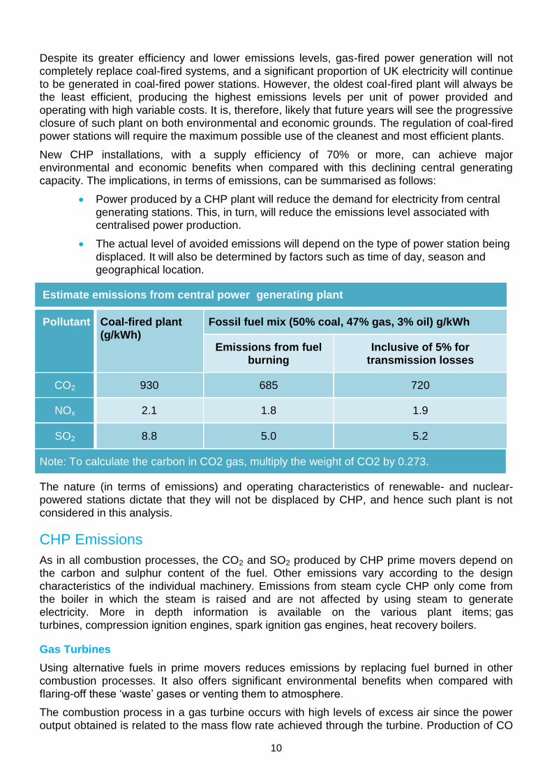
Despite its greater efficiency and lower emissions levels, gas-fired power generation will not completely replace coal-fired systems, and a significant proportion of UK electricity will continue to be generated in coal-fired power stations. However, the oldest coal-fired plant will always be the least efficient, producing the highest emissions levels per unit of power provided and operating with high variable costs. It is, therefore, likely that future years will see the progressive closure of such plant on both environmental and economic grounds. The regulation of coal-fired power stations will require the maximum possible use of the cleanest and most efficient plants.
New CHP installations, with a supply efficiency of 70% or more, can achieve major environmental and economic benefits when compared with this declining central generating capacity. The implications, in terms of emissions, can be summarised as follows:
Power produced by a CHP plant will reduce the demand for electricity from central generating stations. This, in turn, will reduce the emissions level associated with centralised power production.
The actual level of avoided emissions will depend on the type of power station being displaced. It will also be determined by factors such as time of day, season and geographical location.
Estimate emissions from central power generating plant
Pollutant Coal-fired plant (g/kWh)
Fossil fuel mix (50% coal, 47% gas, 3% oil) g/kWh
Emissions from fuel burning
Inclusive of 5% for transmission losses
CO2 930 685 720
NOx 2.1 1.8 1.9
SO2 8.8 5.0 5.2
Note: To calculate the carbon in CO2 gas, multiply the weight of CO2 by 0.273.
The nature (in terms of emissions) and operating characteristics of renewable- and nuclear-powered stations dictate that they will not be displaced by CHP, and hence such plant is not considered in this analysis.
CHP Emissions
As in all combustion processes, the CO2 and SO2 produced by CHP prime movers depend on the carbon and sulphur content of the fuel. Other emissions vary according to the design characteristics of the individual machinery. Emissions from steam cycle CHP only come from the boiler in which the steam is raised and are not affected by using steam to generate electricity. More in depth information is available on the various plant items; gas turbines, compression ignition engines, spark ignition gas engines, heat recovery boilers.
Gas Turbines
Using alternative fuels in prime movers reduces emissions by replacing fuel burned in other combustion processes. It also offers significant environmental benefits when compared with flaring-off these ‘waste’ gases or venting them to atmosphere.
The combustion process in a gas turbine occurs with high levels of excess air since the power output obtained is related to the mass flow rate achieved through the turbine. Production of CO

11
and UHC is very low under normal conditions. NOX emissions are normally low. Gas turbines that cannot meet the appropriate levels are sometimes fitted with water or steam injection systems to reduce NOX output.
The NOX emissions shown in the table below are based on turbines complying with the current guidance value, and many units are capable of even lower NOx output. For turbines with a net thermal input of 50 MW and above, are 60 mg/m3 on gas firing and 125 mg/m3 on oil firing. For turbines with a net thermal input of 20-50 MW, the values are 125 mg/m3 on gas firing and 165 mg/m3 on oil firing .
Emissions from gas turbines
NOx (g/kWh) CO2 (g/kWh) SO2 (g/kWh)
Gas turbines of 50MW thermal input or greater
Firing on natural gas 0.5 510 nil
Firing on gas-oil 1.0 670 1.2
Gas turbines of less than 50MW thermal input
Firing on natural gas 1.1 610 nil
Firing on gas-oil 1.6 800 1.4
These data represent typical values based on the emissions criteria set in the relevant Guidance Notes and typical efficiencies of 35% for turbines with a thermal input of 50 MW and above, and 30% for turbines with a thermal input of 20-50 MW.
Gas turbines for CHP can also use other gaseous fuels:
Methane-based fuel gases from landfill sites, sewage treatment works and mine
ventilation systems contain high levels of inert constituents such as nitrogen and
CO2. However, using these fuels in place of natural gas reduces NOX emissions by
more than 50% because of the lower combustion temperatures involved.
Refinery gases have a high hydrogen content and their use results in NOX
emissions that are up to 2.5 times higher than those obtained with natural gas,
although the lower carbon content of the fuel reduces CO2 emissions.
Compression-ignition Engines
Compression-ignition engines generally operate with lower air-to-fuel ratios and higher
combustion temperatures than gas turbines. The aim is to maximise efficiency but the result in environmental terms is to give relatively high NOX emissions levels per unit of power generated. Actual NOX emissions vary widely between different engine designs: in some cases, it is possible to reduce NOX emissions by operating at a lower engine efficiency, albeit with a small increase in CO2 emissions.
Compression-ignition engines can operate on gas fuels if a small quantity of ‘pilot oil’ is injected to ignite the gas. This fuel option gives lower NOX emissions than fuel oil but usually reduces the power output of the engine.

12
Emissions from compression-ignition engines
NOx (g/kWh) CO2 (g/kWh) SO2 (g/kWh)
Firing on natural gas (with pilot oil) 5-10 500-600 0.1
Firing on heavy fuel oil 8-15 700-800 10.8
Spark-ignition Gas Engines
Spark ignition gas engines are now a viable option for industrial CHP applications, thanks to recent advances in the manufacture of larger and more efficient engines. These engines operate on natural gas and are based on lean-burn combustion technology to enable them to meet the strict NOX emissions limits that apply in most European countries. Typical emissions from spark-ignition gas engine CHP units are given below.
Emissions from spark-ignition gas engines
NOx (g/kWh) CO2 (g/kWh) CO (g/kWh) SO2 (g/kWh)
Firing on natural gas
5-20 500-600 1-2 Negligible
Note: These data represent typical values based on the emissions criteria set in the relevant Guidance Notes and typical engine efficiencies of 35% to 40%.
Heat Recovery Boilers
Replacing conventional boilers with the supplementary firing of a heat recovery boiler increases the environmental benefits of a CHP installation.
The heat recovery boiler in a CHP installation is where heat is recovered from the prime mover exhaust and used to raise steam or hot water. Heat recovery has no effect on the composition of the prime mover exhaust gases, although it can result in acid condensation if temperatures fall too low.
However, a heat recovery boiler can incorporate supplementary firing to improve boiler output. This uses the prime mover exhaust in place of ambient air and is a more energy-efficient way of raising additional heat than using a conventional boiler. Carbon dioxide emissions are up to 10% less than CO2 emissions from conventional boilers.
Because the exhaust gases used in supplementary firing contain less oxygen than ambient air, the NOx emissions level is typically about half that produced by a conventional boiler burning
the same quantity and type of fuel. Furthermore, tests have shown that, under certain firing conditions, supplementary firing adds no further NOx to the prime mover exhaust gases.
CHP Emission Reductions
A CHP plant that is well designed and operated will always improve energy efficiency and significantly reduce CO2 emissions. Where power from a CHP plant replaces electrical power from older coal-fired power stations, there is also a significant reduction in SO2 and NOX emissions because of the lower sulphur content of the fuel and the use of more modern combustion equipment.

13
Typical emissions from a range of CHP installations, based on emissions from the prime movers and boilers, enable emissions savings to be calculated for a range of CHP options and existing boiler types. Such data are indicative of the benefits that can be achieved using CHP. The actual benefits in respect of emissions reductions will depend on the specific characteristics and operating conditions of a plant. The principles can, however, be applied to determine the predicted benefits of a scheme once the major components are selected. Actual benefits can be determined through plant monitoring once the system is operational.
The following table summarises typical emissions from a range of CHP installations. It is based on emissions from the prime movers and boilers. The table also shows the typical heat to power ratio for each scheme.
Typical emissions from CHP systems
A B C D E F G H
CHP system
type
Gas
turbine
with heat
recovery
boiler
Gas
turbine
with heat
recovery
boiler and
back-
pressure
steam
turbine
Boiler and
back-
pressure
steam
turbine
Boiler and
back-
pressure
steam
turbine
Boiler and
back-
pressure
steam
turbine
CI engine
with heat
recovery
boiler
CI engine
with heat
recovery
boiler
Lean-burn
SI engine
with heat
recovery
boiler
Fuel type Natural
gas
Natural
gas
Natural
gas HFO Coal
Natural
gas HFO
Natural
gas
Emissions in g/kWh of electrical power produced
CO2 610 510 1,510 2,220 2,700 570 800 500
NOx 1.1 0.9 1.5 5.3 5.2 5-10 8-15 3
SO2
nil nil nil
28.2 (2.0%
sulphur in fuel)
20.6 (1.2%
sulphur in fuel)
nil
8.4 (2.0%
sulphur in fuel)
nil
Ratio of recovered heat to power
generated
1.6:1 1.1:1 5.5:1 5.5:1 5.5:1 1.4:1 1.4:1 1.6:1
Note 1: NOx emission/kWh from gas turbines increase/decrease in proportion to the turbine emissions rate expressed in parts/million (ppm)
Note 2: Datum used is 60ppm for natural gas firing
Note 3: So2 emissions from all plant increase/decrease in proportion to sulphur content of fuel
14
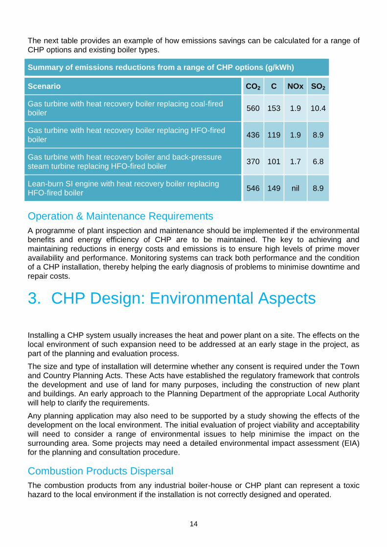
The next table provides an example of how emissions savings can be calculated for a range of CHP options and existing boiler types.
Summary of emissions reductions from a range of CHP options (g/kWh)
Scenario CO2 C NOx SO2
Gas turbine with heat recovery boiler replacing coal-fired boiler
560 153 1.9 10.4
Gas turbine with heat recovery boiler replacing HFO-fired boiler
436 119 1.9 8.9
Gas turbine with heat recovery boiler and back-pressure steam turbine replacing HFO-fired boiler
370 101 1.7 6.8
Lean-burn SI engine with heat recovery boiler replacing HFO-fired boiler
546 149 nil 8.9
Operation & Maintenance Requirements
A programme of plant inspection and maintenance should be implemented if the environmental benefits and energy efficiency of CHP are to be maintained. The key to achieving and maintaining reductions in energy costs and emissions is to ensure high levels of prime mover availability and performance. Monitoring systems can track both performance and the condition of a CHP installation, thereby helping the early diagnosis of problems to minimise downtime and repair costs.
3. CHP Design: Environmental Aspects
Installing a CHP system usually increases the heat and power plant on a site. The effects on the local environment of such expansion need to be addressed at an early stage in the project, as part of the planning and evaluation process.
The size and type of installation will determine whether any consent is required under the Town and Country Planning Acts. These Acts have established the regulatory framework that controls the development and use of land for many purposes, including the construction of new plant and buildings. An early approach to the Planning Department of the appropriate Local Authority will help to clarify the requirements.
Any planning application may also need to be supported by a study showing the effects of the development on the local environment. The initial evaluation of project viability and acceptability
will need to consider a range of environmental issues to help minimise the impact on the surrounding area. Some projects may need a detailed environmental impact assessment (EIA) for the planning and consultation procedure.
Combustion Products Dispersal
The combustion products from any industrial boiler-house or CHP plant can represent a toxic hazard to the local environment if the installation is not correctly designed and operated.

15
Environmental legislation requires the installation to minimise the production of airborne pollutants, and those that are released must be adequately dispersed within the atmosphere. The UK Government and the devolved administrations published the latest Air Quality Strategy for England, Scotland, Wales and Northern Ireland in July 2007 - setting out a way forward for work and planning on air quality issues and the air quality standards and objectives to be achieved; introducing new policy framework for tackling fine particles and identifying potential new national policy measures which modelling indicates could give further health benefits and move closer towards meeting the Strategy’s objectives
Adequate pollutant dispersion can be achieved by ensuring that atmospheric discharge occurs at a sufficient height above the surrounding area. The required chimney height for any installation is determined by a wide range of factors, including the content of the exhaust and its temperature and velocity, the quality of the background air, and the topography and climate of the local area. Details are given in two documents:
Technical Guidance Note (Dispersion) D1, Guidelines on Discharge Stack Heights
for Polluting Emissions.
Chimney Heights: Third Edition of the 1956 Clean Air Act Memorandum.
Erecting a new chimney has a visual impact on the surrounding area. However, chimney height can be minimised by combining the cleanest practicable combustion technology with low-sulphur fuel. Modern computer modelling systems can assess ground level impact by predicting the local concentration of pollutants that will arise from any combustion plant and any chimney height for specified local conditions.
Noise
All CHP systems have a prime mover/electrical generator which emits ambient noise into the adjacent area and exhaust noisefrom the exhaust stream. Most CHP systems also have items of auxiliary equipment which generate noise either continually or intermittently.
The following table gives typical noise levels for a range of sources and locations
Typical noise levels for a range of sources and locations
Source Typical noise level dB(A)
Public library 35-40
Business premises/offices 55-65
Passing vehicle 75-90
Pneumatic road-breaking drill 95-110
Jet aircraft on take-off 110-125
CHP plant with normal acoustic equipment Around 80
In practice, all noise sources emit sounds over a range of audible frequencies. The ‘A’ scale of measurement simulates the sensitivity of the human ear to different frequencies.
Although the human ear is less sensitive to sound below 1,000Hz, noise at lower frequency is attenuated less by acoustic shielding. It is, therefore, important to consider the characteristics of different noise sources and the effect of acoustic insulation on sound reduction over the full frequency range detected by the human ear.

16
Both intermittent noise and noise sources that emit discrete tones can cause a nuisance. CHP installations usually operate continuously, but care must also be taken to shield sources of intermittent noise such as safety vents, pumps and compressors.
Designing a CHP installation often involves investigating the effects of the plant on the existing local noise profile. This should include surveying existing noise levels at relevant points around the site and assessing how each part of the system contributes to the total level.
Noise levels that damage health, or are a nuisance, are classified as ‘statutory nuisances’ under the Environmental Protection Act 1990, and Local Authorities have a duty to investigate any complaints.
Exhaust Noise
Engines and gas turbines frequently require a silencer in the ductwork or chimney to reduce exhaust noise. Factors that determine this requirement include chimney height, the type of engine or turbine, and the design of the waste heat recovery system. However, it may be possible to reduce the size or specification of a silencer where a heat recovery boiler attenuates the sound of the prime mover.
The following table illustrates typical exhaust noise profiles for gas turbines and reciprocating engines. It clearly shows that, in general, all prime movers give out more noise at lower frequencies, particularly reciprocating engines. The noise level from gas turbines is less variable over the spread of frequencies examined.
Typical exhaust noise levels from CHP prime movers
Frequency (Hz)
125 250 500 1,000 2,000 4,000 8,000
Gas turbine (dB) 120 120 116 112 110 105 95
Reciprocating engine (dB) 125 126 120 112 100 92 82
To meet local environmental requirements, exhaust silencer design for prime mover exhausts must consider the sound level profile. Silencers are available that reduce noise levels to 80 dB(A) at the chimney outlet. However, such a unit must operate without creating an excessive pressure drop across the silencer, as this can affect the prime mover’s performance and efficiency.
Irrespective of whether the waste heat recovery system acts as an effective noise attenuator or incorporates its own silencer, most CHP systems include an exhaust bypass, sometimes with a separate stack, so that the prime mover can operate for short periods without any heat recovery. These bypass arrangements must incorporate a silencer if noise levels at the stack
exit are to be acceptable.
Ambient Noise
An acoustic enclosure is usually installed around the CHP prime mover/electrical generator to reduce ambient noise levels, and the plant itself is often installed in a building that has been specially designed to attenuate noise.
The design of the acoustic enclosure should take into account the fact that, at low frequencies, reciprocating engines tend to make more noise than gas turbines. Foundations and engine mountings therefore need to control engine vibrations, particularly from the larger low-speed

17
machines. Gas turbines do not vibrate as much, but the design of a turbine’s combustion air intake requires acoustic control. The ventilation inlet and outlet ducts on the acoustic enclosures of both engines and gas turbines will probably require small silencers.
The range of auxiliary equipment associated with a CHP system – fans, pumps and motors – may also require noise attenuation. Fuel or air compression systems, in particular, require acoustic enclosures or buildings to suppress the noise they generate.
Visual Impact
A CHP installation requires buildings for the prime mover and boiler, and for auxiliary equipment such as pumps and compressors. These buildings are often constructed on the edge of an industrial site to be close to gas and electricity systems. The design should, therefore, take into account the building’s visual impact on the local area, particularly where it can be seen by the public.
Local Authority planning requirements may place restrictions on building design and require
trees or other barriers to screen the site. The relevant Local Authority departments should be able to provide the necessary advice. Early consultation with these departments and with other community organisations is essential to identify possible problem areas that might otherwise delay the project.
Liquid Effluents Disposal
A CHP plant does not generate large quantities of liquid effluent. However, the following effluents can cause environmental damage if not controlled, and appropriate account should be taken of these at the system design stage:
Boiler blowdown and drain effluent contain suspended solids and quantities of the
chemicals used for treating boiler feed-water. The total water content of the boiler
needs to be drained through the system for boiler maintenance and inspection
purposes. There are limits on the temperature at which any effluent can be
discharged.
Effluent is generated by plant cleaning procedures such as turbine washing systems.
Where periodic washing and system regeneration has necessitated the installation
of a water treatment plant, this will also give rise to effluent.
Pipework flushing and the chemical cleaning of equipment during installation and
commissioning produces effluent.
Disposing of any liquid effluent to a public sewerage system or into the environment must have approval from the appropriate authority. Some form of treatment may be required for these effluents, and some sites have a suitable existing effluent treatment system. In some cases, effluent will need to be put in containers, removed from site, and disposed of by specialist contractors.
Containment & Storage
A range of potentially environmentally damaging materials is used in operating CHP plant and its auxiliary equipment. Precautions must be taken both at the design stage and during operation to prevent accidental releases. This may mean incorporating detection and alarm systems.

18
There are numerous design and engineering standards and codes of practice to improve safety and reduce the risk to the environment of accidental leaks or spills of hazardous substances such as natural gas, oils & chemicals and coal.
Natural Gas
All fittings and pipework must be designed, and installed, to meet specifications and
regulations.
The system must be specified and tested for soundness throughout its service life.
Oils & Chemicals
In areas of risk, gas leakage detection systems are recommended, together with an automatic supply shut-off facility in the event of a leakage.
All liquid substances used in bulk by a CHP plant, for example, fuels, lubricants and
chemicals, should be stored in tanks.
All tanks should be located within a catchment bund (secondary containment
system) that is large enough to contain 110% of the tank's maximum capacity.
Unloading points for bulk delivery vehicles should be designed to contain any
spillages in a safe area.
Water treatment plant and similar facilities should be sited in a bunded area to
contain spillages.
A bunded area should be available for storing materials supplied in portable
containers, together with procedures and equipment for safe handling.
It is advisable to incorporate a sump to contain any liquids from surface drains in and around the CHP plant. This ensures that all types of liquid can be disposed of safely.
Coal storage & handling
Coal must be delivered into a safe and secure storage area.
The coal storage area must be ventilated to prevent a build-up of methane gas.
Coal should be handled in a way that minimises the creation of airborne dust and
particles. It may be necessary to install water sprinklers to dampen down material
prior to handling.
Run-off water must be collected and treated to meet appropriate discharge
requirements.
4. Legislation
Legislation and regulations are subject to frequent change. The contents of this section are not, therefore, definitive and are intended for guidance purposes only. Readers must make their own judgements and take responsibility for how they use the information. Incuded are sections on:
UK legislation for combustion processes and

19
CHP Pollution Control
Combustion Processes: UK Legislation
Environmental regulation in the UK is based on a number of Acts of Parliament enacted for the benefit of the UK, together with legislation designed to meet EU environmental requirements.
The Environmental Protection Act 1990 (EPA) was introduced as the main legislation controlling atmospheric emissions and other types of pollution in the UK. It established an integrated system to control pollution from industry, and encompassed many of the diverse requirements of previous pieces of legislation such as the Public Health Acts, the Alkali Act and the Control of Pollution Act. It was also the means by which the UK complied with the EU Directive on Large Combustion Plant.
The EPA introduced a formal system of permits and reviews to ensure acceptable levels of environmental performance for a wide range of industrial processes. For each environmental medium, the EPA defined ‘prescribed' substances, i.e. substances that are potentially harmful and need to be controlled to prevent, or minimise, their discharge into the environment. The Act also introduced the principle of Best Available Techniques Not Entailing Excessive Cost (BATNEEC) as the criterion for regulating the release of these prescribed substances.
The EPA does not apply in Northern Ireland, where pollution control is regulated by the Environment and Heritage Service.
The Environment Act 1995 created a unified Environment Agency (EA) in England and Wales, and the Scottish Environment Protection Agency (SEPA) in Scotland.
The Act made provision for a National Air Quality Strategy, under which the Government has set out its policies regarding the assessment and management of air quality. The implementation of EC legislation and international agreements is included within the scope of the strategy. This strategy is required to determine:
Standards relating to air quality.
Objectives for restricting the levels at which particular substances are present in the
air.
Measures to be taken by local authorities and other persons for the purposes of
achieving these objectives.
The Environment Act 1995 also places a requirement on Local Authorities to carry out air quality reviews.
The Pollution Prevention and Control Act 1999 made changes in environmental legislation with effect from 1 November 1999. These changes were initiated by the EU Directive on Integrated Pollution Prevention and Control (IPPC), and the new Act replaced Part 1 of the Environmental Protection Act 1990. Under this new Act, the Pollution Prevention and Control (PPC) Regulations 2000 formed the basis for the new IPPC regime for the UK.
The IPPC directive required operators of regulated plants to use Best Available Techniques (BAT), which is very similar in principle to the BATNEEC defined in earlier UK legislation; the issue of both economic and technical feasibility is contained within both definitions. The Act confirmed the role of the UK's Environment Agencies and Local Authorities as the regulators/enforcers of pollution control for a widened range of commercial and agricultural activities.

20
The Environmental Permitting Regulations (EPR) came into force on 6 April 2008. These new regulations will make existing legislation more efficient by combining Pollution Prevention and Control (PPC) and Waste Management Licensing (WML) regulations.
Following a review of existing European industrial emissions legislation, the European Commission adopted a proposal for a Directive on Industrial Emissions on the 21st December 2007. The Industrial Emissions Directive (IED) is a recast of the following seven existing directives into a single clear and coherent directive:
Large Combustion Plant Directive Directive (LPC)
Integrated Pollution Prevention Control Directive (IPPC)
Waste Incineration Directive (WID)
Solvents Emissions Directive (SED)
Three Titanium Dioxide Directives
The IED aims to remove the ambiguities and uncertainties in the component directives which it replaces but does not change the underlying principles.
The IED was adopted by the European commission on 24th Novemeber 2010 and came into force on the 6th January 2011. Member states must transpose the IED into national legislation by the 6th January 2013. The IED will then be implemented from:
6th January 2013 for any new installation from this date onwards
6th January 2014 for installations in existence prior to 6th January 2013
6th January 2015 for installations not subject to current IPPC
In England and Wales the IED will be implemented though a revision of the EPR. DEFRA has recently undertaken a consultation on the transposition of the IED in England and Wales, the results of which are expected imminently.
CHP Pollution Control
For CHP plants, the regulatory system takes no account of whether heat is recovered from a prime mover, or whether steam from a boiler is used to drive a turbine; it is the fuel-burning components, i.e. the gas turbines, the engines and the boilers, that are regulated as combustion processes. The only aspect of CHP that may be treated as a different case is that of supplementary firing.
The degree of environmental regulation that applies to CHP plants depends on the size and type of the plant. Within the Pollution Prevention and Control (PPC) Regulations, a thermal input capacity of 50MW was retained as the threshold above which a combustion process or installation will be regulated as a ‘Part A’ plant under either IPPC or IPC. These plants are regulated by the EA in England and Wales, and by SEPA in Scotland.
In addition, a CHP plant that is part of any industrial installation regulated under IPPC is considered as being part of that installation, since it is a directly associated activity that is technically connected to the main installation. The CHP plant must therefore be included in the operator’s IPPC application; if the CHP plant is under the control of a separate operator, then that operator must submit a separate IPPC application in conjunction with the one submitted by the operator of the main installation. Combustion plant that is rated at 20-50MW thermal input is regulated as ‘Part B’ plant in terms of emissions. In England and Wales, Part B regulation is the responsibility of the Local Authority, and is known as Local Authority Pollution Prevention and Control (LAPPC). In Scotland, SEPA are responsible for Part B plants.

21
All CHP plants, including plants that do not fall into either of the above two categories, are required to comply with any general legislation on pollution control (and in particular the Clean Air Acts), and the remaining sections of the EPA which cover nuisance to neighbours and the public.
The Environmental Permitting (EP) Regulations came into force on 6 April 2008. These new regulations will make existing legislation more efficient by combining Pollution Prevention and Control (PPC) and Waste Management Licensing (WML) regulations.
Since the introduction of Part A processes/ installations and Part B processes/installations under the EPA in 1990, a series of Process Guidance Notes has been produced to give information and guidance on the operation of combustion plant to both the regulatory organisations and to the operators of regulated sites. These have been produced and updated since 1990, and are now the responsibility of the EA/SEPA.
Part A Processes/Installations
CHP plants with a thermal input capacity of more than 50MW are regulated as Combustion
Activities (as are any CHP plants that are part of a broader industrial installation) within the Environmental Permitting (EP) Regulations that came into force on 6 April 2008. The thermal input of all plant items is aggregated for comparison with the 50MW threshold. For example, a plant that consists of three gas turbines, each with a thermal input of 18MW, will be considered as a single gas turbine plant of 54MW and will be subject to Part A regulation. Likewise, a boiler-house containing five boilers, each with a thermal input of 12MW, will be regulated as a 60MW boiler plant. A plant consisting of one gas turbine with a thermal input of 18MW, with two boilers each of 20MW thermal input, will be regulated as a 58MW combustion installation.
Defra has produced a series of guidance documents including Core Guidance which describes the general permitting and compliance requirements and guidance on the European directives which are implemented through the Environmental Permitting Regulations. The documents also include guidance on the Large Combustion Plant Directive (Article 6 covers CHP permitting requirements).
In addition to Defra's guidance, the EA have produced guidance on the parts of the regulations that they are responsible for (Part A(1) activities and Waste Operations). Their guidance includes Technical Guidance Notes, risk assessment tool, application form and form guidance.
These documents are intended as guidance to the regulators and to plant operators in general, and provide a basis for the conditions and environmental performance that will be required under a permit from the EA/SEPA.
One of the key legislative issues that affects authorisations is the Air Quality Strategy and the need for the UK to achieve its targets on Ambient Air Quality, so plants located in areas with a risk of poor air quality may be expected to achieve tighter emission limits.
Part B Processes / Installations
Combustion plant with a thermal input capacity of 20-50MW will generally be regulated by Local Authorities in England and Wales (under LAPPC) and by SEPA in Scotland.
The relevant Guidance Notes issued by Defra, are:
PG1/3 Boilers and Furnaces, 20-50MW Net Rated Thermal Input.
PG1/4 Gas Turbines, 20-50MW Net Rated Thermal Input.
PG1/5 Compression-ignition Engines, 20-50MW Net Rated Thermal Input.

22
These Guidance Notes are issued as a guide to local enforcing authorities on the techniques appropriate for the control of air pollution for the process.
In the case of Part B plants, it is the rated input of the individual gas turbine, engine or boiler that is compared with the 20-50MW threshold and regulated accordingly. Aggregation of the rating of multiple units of plant is not carried out.
5. Meeting Environmental Requirements
Increasing levels of environmental regulation will encourage the more efficient use of primary fuels and energy, and the replacement of older equipment and techniques. Any organisation considering the viability of CHP should therefore make a quantitative assessment of the reduction in emissions that CHP can achieve.
When assessing the viability of a CHP scheme, an early approach to the Local Authority
Planning and Environmental Departments should give an indication of the potential environmental sensitivity of the scheme. In particular, it should be possible to assess the design aspects required to meet air quality targets and other local requirements. It may be appropriate at this stage to prepare a brief initial statement defining the extent of the scheme and assessing its environmental effects. This can be published early on for consultation with local interest groups.
Once the size and type of scheme have been defined, it is important – if appropriate – to discuss the proposals with the regulatory authority. This should confirm which pollution control authority will regulate the operation of the CHP scheme and give firm guidance on the environmental performance conditions that will be applied.
As a general rule:
If the CHP scheme proposed has a fuel input of 50MW or more, contact the
Environment Agency, the Scottish Environment Protection Agency or, for Northern
Ireland, the Environment and Heritage Service.
If the CHP scheme proposed has a fuel input of 20-50MW, contact the Local
Authority Environmental Health Department or the Scottish Environment Protection
Agency.
If the CHP scheme proposed has a fuel input below 20MW, refer to the Clean Air Act
1993 requirements and contact the Local Authority.

23

© Crown copyright 2008
Department of Energy & Climate Change
3 Whitehall Place
London SW1A 2AW
www.gov.uk/decc
Version 1