a gui application for controlling handheld radar devices ...439145/fulltext02.pdf · a gui...
TRANSCRIPT

A GUI Application for Controlling Handheld
Radar Devices via Bluetooth and a Suitability
Study of ZigBee
Master Thesis in Communication Systems
by
Ragnar Wichers
LiTH-ISY-EX--11/4384--SE
2011-09-05


A GUI Application for Controlling Handheld Radar Devices
via Bluetooth and a Suitability Study of ZigBee
Master Thesis in Communication Systems
at Linköping Institute of Technology
by
Ragnar Wichers
LiTH-ISY-EX--11/4384--SE
Examiner : Associate Professor Mikael Olofsson
Dept. of Electrical Engineering
Linköping 2011-09-05


Presentationsdatum 2011-08-22
Publiceringsdatum 2011-09-05
Institution och Avdelning Institutionen för Systemteknik Avdelningen för Kommunikationssystem
Division and Department Department of Electrical Engineering Division of Communication Systems
URL för elektronisk version http://www.ep.liu.se
Publikationens titel En GUI-applikation för styrning av handhållna radarenheter via Bluetooth samt en lämplighetsstudie av ZigBee
Författare Ragnar Wichers
Sammanfattning CPR3 är en handhållen radarenhet. Denna enhet är kapabel att detektera rörelse genom väggar och är huvudsakligen menad för polis och militär. Den är utrustad med en Bluetooth-modul vars uppgift är att möjliggöra fjärrstyrning. För att öka användarnas mobilitet så utvecklas en Windows Mobile-applikation. Denna applikation är menad att ersätta en redan existerande Windows-applikation som används för att fjärrstyra dessa radarenheter. Det utförs även en mindre utvärdering av applikationsramverket. Dessutom utförs en teoretisk prestanda analys av ZigBee-standarden. Målet är att visa om ZigBee är en lämplig ersättare för Bluetooth som det primära kommunikationsmedlet inom systemet.
Nyckelord Windows Mobile, Qt, Bluetooth, ZigBee
Språk
Svenska X Annat (ange nedan) Engelska
Antal sidor 36
Typ av publikation
Licentiatavhandling X Examensarbete C-uppsats D-uppsats Rapport Annat (ange nedan)
ISBN
ISRN LiTH-ISY-EX--11/4384--SE
Serietitel
Serienummer/ISSN


Abstract
The CPR3 is a handheld radar device. This device is capable of detecting movement
through walls and is mainly intended for police and military use. It is equipped with
a Bluetooth module that enables remote control. To enhance the mobility of the users
that utilize this functionality, a Windows Mobile application is developed. This appli-
cation is meant to replace the already existing Windows application used for remotely
controlling these radar devices. Furthermore, a small evaluation of the framework used
for the development of the application is performed.
Also, a theoretical performance analysis is performed on the ZigBee standard. The
goal is to find out whether or not ZigBee is a suitable replacement technology for
Bluetooth as the primary means of communication within the system.


Acknowledgement
First of all, I would like to thank my supervisor, Associate Professor Mikael Olofsson,
for all the support and patience throughout this ordeal. Furthermore, I would like to
thank everyone at Cinside for the opportunity to work on the CPR3 project. Also,
I am eternally grateful to Christian Vestlund for his helpful comments on the report.
Lastly, I would like to thank my parents who never gave up on me. Who says nagging
does not work?


Contents
1 Introduction 1
1.1 Problem Background . . . . . . . . . . . . . . . . . . . . . . . . . . . . . . . . . . . . . 1
1.2 Definition of Problem . . . . . . . . . . . . . . . . . . . . . . . . . . . . . . . . . . . . 1
1.3 Methodology . . . . . . . . . . . . . . . . . . . . . . . . . . . . . . . . . . . . . . . . . 2
1.4 Delimitations . . . . . . . . . . . . . . . . . . . . . . . . . . . . . . . . . . . . . . . . . 2
1.5 Disposition . . . . . . . . . . . . . . . . . . . . . . . . . . . . . . . . . . . . . . . . . . 2
2 Background 3
2.1 Bluetooth Programming . . . . . . . . . . . . . . . . . . . . . . . . . . . . . . . . . . . 3
2.1.1 Essential Concepts . . . . . . . . . . . . . . . . . . . . . . . . . . . . . . . . . . 3
2.1.2 Choosing a Target Device . . . . . . . . . . . . . . . . . . . . . . . . . . . . . . 3
2.1.3 Choosing a Transport Protocol . . . . . . . . . . . . . . . . . . . . . . . . . . . 6
2.1.4 Communicating via Sockets . . . . . . . . . . . . . . . . . . . . . . . . . . . . . 7
2.1.5 Bluetooth Stacks . . . . . . . . . . . . . . . . . . . . . . . . . . . . . . . . . . . 9
2.2 Introduction to Qt . . . . . . . . . . . . . . . . . . . . . . . . . . . . . . . . . . . . . . 9
2.2.1 Signals and Slots . . . . . . . . . . . . . . . . . . . . . . . . . . . . . . . . . . . 9
2.2.2 Layout Methods . . . . . . . . . . . . . . . . . . . . . . . . . . . . . . . . . . . 10
2.3 Introduction to ZigBee . . . . . . . . . . . . . . . . . . . . . . . . . . . . . . . . . . . . 10
2.3.1 Architecture . . . . . . . . . . . . . . . . . . . . . . . . . . . . . . . . . . . . . 10
2.3.2 Frequencies of Operation and Data Rate . . . . . . . . . . . . . . . . . . . . . . 11
2.3.3 Device Types . . . . . . . . . . . . . . . . . . . . . . . . . . . . . . . . . . . . . 12
2.3.4 Device Roles . . . . . . . . . . . . . . . . . . . . . . . . . . . . . . . . . . . . . 12
2.3.5 Network Topology . . . . . . . . . . . . . . . . . . . . . . . . . . . . . . . . . . 12
2.3.6 ZigBee and IEEE 802.15.4 Communication Basics . . . . . . . . . . . . . . . . 13
2.3.7 ZigBee Self-Forming and Self-Healing . . . . . . . . . . . . . . . . . . . . . . . 14
2.4 CPR3 Transport Protocol . . . . . . . . . . . . . . . . . . . . . . . . . . . . . . . . . . 14
2.4.1 Structure for Messages to CPR3s . . . . . . . . . . . . . . . . . . . . . . . . . . 14
2.4.2 Structure for Messages from CPR3s . . . . . . . . . . . . . . . . . . . . . . . . 14
3 CiTerm 17
3.1 Use-Case Scenario . . . . . . . . . . . . . . . . . . . . . . . . . . . . . . . . . . . . . . 17
3.2 Software Requirements . . . . . . . . . . . . . . . . . . . . . . . . . . . . . . . . . . . . 17
3.3 Application Design . . . . . . . . . . . . . . . . . . . . . . . . . . . . . . . . . . . . . . 17
3.4 Graphical Interface . . . . . . . . . . . . . . . . . . . . . . . . . . . . . . . . . . . . . . 20

4 ZigBee Suitability Evaluation 234.1 Range . . . . . . . . . . . . . . . . . . . . . . . . . . . . . . . . . . . . . . . . . . . . . 234.2 Data Rate . . . . . . . . . . . . . . . . . . . . . . . . . . . . . . . . . . . . . . . . . . . 234.3 Network Latency . . . . . . . . . . . . . . . . . . . . . . . . . . . . . . . . . . . . . . . 264.4 Power Profile . . . . . . . . . . . . . . . . . . . . . . . . . . . . . . . . . . . . . . . . . 27
5 Conclusions 29
A Development Environment 33A.1 Applications and SDKs . . . . . . . . . . . . . . . . . . . . . . . . . . . . . . . . . . . 33A.2 Qt Related Issues . . . . . . . . . . . . . . . . . . . . . . . . . . . . . . . . . . . . . . . 33A.3 Debug Alternatives . . . . . . . . . . . . . . . . . . . . . . . . . . . . . . . . . . . . . . 34

List of Figures
2.1 The major steps for programming an outgoing connection [1, fig 1.1]. . . . . . . . . . . 42.2 The major steps for programming an incoming connection [1, fig 1.2]. . . . . . . . . . 52.3 The steps needed to obtain a connected socket [1, fig 1.6]. . . . . . . . . . . . . . . . . 82.4 The ZigBee wireless networking protocol layers [2, fig 1.14]. . . . . . . . . . . . . . . . 11
3.1 A use-case for the CiTerm application. . . . . . . . . . . . . . . . . . . . . . . . . . . . 183.2 An example of a message from a CPR3 containing radar data. . . . . . . . . . . . . . . 193.3 The available tabs that are found in the CiTerm application. . . . . . . . . . . . . . . 21
4.1 An example of a node constellation in a mesh network. The colored node being thenetwork coordinator and the rest being regular devices. The arrows showing the routefor radar data to be transmitted. . . . . . . . . . . . . . . . . . . . . . . . . . . . . . . 24
4.2 The configuration of the experiments [3, fig 8]. . . . . . . . . . . . . . . . . . . . . . . 254.3 Effictive data rate of CSMA-CA with varied traffic load in a nonbeacon-enabled network
[3, fig 11]. . . . . . . . . . . . . . . . . . . . . . . . . . . . . . . . . . . . . . . . . . . . 254.4 Delivery ratio of CSMA-CA with varied traffic load in a nonbeacon-enabled network
[3, fig 12]. . . . . . . . . . . . . . . . . . . . . . . . . . . . . . . . . . . . . . . . . . . . 264.5 Effictive data rate of CSMA-CA with varied data payload size in a nonbeacon-enabled
network [3, fig 13]. . . . . . . . . . . . . . . . . . . . . . . . . . . . . . . . . . . . . . . 27


List of Tables
2.1 Describes the Inquiry Scan and Page Scan options [1, tab 1.1]. . . . . . . . . . . . . . 62.2 Circumstances under which operations on a blocking socket return [1, tab 1.4]. . . . . 92.3 Commands that are accepted by a CPR3. . . . . . . . . . . . . . . . . . . . . . . . . . 152.4 Commands that are issued by a CPR3. . . . . . . . . . . . . . . . . . . . . . . . . . . . 15
3.1 A collection of the functional requirements. . . . . . . . . . . . . . . . . . . . . . . . . 183.2 A collection of the non-functional requirements. . . . . . . . . . . . . . . . . . . . . . . 18
A.1 Emulator images that are included in the Windows Mobile 6 Professional SDK [4]. . . 34


Nomenclature
AODV Ad hoc On-Demand Distance Vector
APL Application Layer
APS Application Support Sublayer
CCA Clear Channel Assessment
CR Carriage Return
CS Carrier Sense
CSMA-CA Carrier Sense Multiple Access with Collision Avoidance
DLL Dynamic-Link Library
ED Energy Detection
FFD Full-Function Device
GTS Guaranteed Time Slot
GUI Graphical User Interface
L2CAP Logical Link Control and Adaptation Protocol
MAC Machine Address Code
NWK Network
PAN Personal Area Network
PHY Physical
POS Personal Operating Space
RFCOMM Radio Frequency Communication
RFD Reduced-Function Device
SCO Synchronous Connection-Oriented
SDK Software Development Kit
SDP Service Discovery Protocol
SOH Start of Heading
17

UUID Universally Unique Identifier
VS Visual Studio
ZC ZigBee Coordinator
ZDO ZigBee Device Object
ZED ZigBee End-Device
ZR ZigBee Router

Chapter 1
Introduction
The focus of this thesis is firstly the development of an application for the Windows Mobile plat-form. The application has received the name CiTerm and its purpose is to enable remote control ofmultiple handheld radar devices, also known as CPR3s, via Bluetooth. Furthermore, the applicationis constructed with the help of Qt which is a cross-platform development framework. This leads toa discussion about the frameworks relevance when handheld devices are concerned. Lastly, a theo-retical evaluation of the ZigBee standard is done to determine its suitability to replace Bluetooth asthe primary means of communications with the CPR3. Section 1.1 gives a brief motivation for thethesis. Section 1.2 describes the problems at hand. Section 1.3 describes the methodology for thedevelopment of the application but also for the theoretical evaluation of the ZigBee standard. Section1.4 explains the delimitations for the thesis. Finally, Section 1.5 describes the structure of the thesis.
1.1 Problem Background
Cinside is a company that offers handheld radar devices meant to enhance the personal safety ofpolice and military forces. At present, there is a way to supervise deployed radar devices through theuse of an application that runs on a computer. However, the present solution does not support fullmobility. Furthermore, this solution requires direct contact with each of the radar devices which isrestricting movement for users.
1.2 Definition of Problem
Cinside desires an application on the Windows Mobile platform for supervision and remote controlof their handheld radar devices. Additional conditions are that the Qt cross-platform frameworkshould be used when creating the application and that it should use Bluetooth to communicate withthe radar devices. Furthermore, Cinside requests a small evaluation regarding Qt and its relevancewhen handheld devices are concerned. It is also requested that a theoretical study be made regardingwhether ZigBee would be a suitable replacement technology for Bluetooth. This would allow theusers to move more freely in the environment due to the fact that the ZigBee specification includesthe forming of mesh networks.
1

2
1.3 Methodology
The first step was to read related literature in order to obtain a basic understanding of the differenttechnologies involved. Then, the requirement specification for the prototype was created. Next, thedevelopment environment was installed so that the development of the prototype could begin. Oncethe prototype was done, the search for additional information began. This information would bethe foundation of the ZigBee and Qt evaluation. The last step was to summarize the study and itsfindings into this thesis.
1.4 Delimitations
The application Cinside desires is meant to be a prototype. Its purpose is to show that Cinside’s needsmentioned in Section 1.2 can be met. Also, Qt is the only cross-platform development frameworkdiscussed in this thesis. Furthermore, the evaluation of the ZigBee specification is done theoretically.
1.5 Disposition
The thesis is outlined as follows:
Chapter 1 presents the introduction, problem statements and the methodology used for this thesis.
Chapter 2 provides background and basic concepts which is necessary for the understanding of thethesis.
Chapter 3 provides information about the CiTerm application.
Chapter 4 provides an evaluation of the ZigBee specification.
Chapter 5 concludes the thesis and presents suggestions for future work.

Chapter 2
Background
This section is to give the reader basic understanding of the different elements concerning this thesis.
2.1 Bluetooth Programming
In this section the essentials for Bluetooth programming will be discussed.
2.1.1 Essential Concepts
In the process of establishing a connection between two Bluetooth devices, there must always be aclient and a server present [1, ch 1]. The main difference between the two is that only one of themsends the first data packet that initiates communications. Important to understand is that this hasnothing to do with the Client-Server model of network programming [1, ch 1]. This means that aninitiating device, i.e. a client, can function as a server in the Client-Server model sense, and vice versa.
Before a device can establish an outgoing connection and transfer data, it needs to choose a targetdevice and a transport protocol [1, ch 1]. Similarly, a device that wants to establish an incomingconnection needs to choose a transport protocol and then listen before accepting a connection andtransferring data. These basic concepts are illustrated in Figures 2.1 and 2.2.
2.1.2 Choosing a Target Device
When a Bluetooth chip is manufactured it is given a globally unique 48-bit address, also calledBluetooth address or device address [1, ch 1]. This address serves the same purpose as the MachineAddress Code (MAC) address does in the case of Ethernet communication. The main difference isthat while the Bluetooth address is used in all layers of the Bluetooth communication process theMAC address is discarded at higher layers of the Ethernet communication process. That aside, theyboth work as a unique identifying address of the target device and must therefore be known in orderto communicate with it.
In some cases the client application needs the user to provide the user-friendly name of the targetdevice [1, ch 1]. This is then translated to a numerical address and compared to all the names ofnearby Bluetooth devices. These user-friendly names (also called the display names) exist to helpusers by not forcing them to remember 48-bit long Bluetooth addresses. There is nothing stopping twodevices from having the same name, which can cause confusion when they are in the vicinity of eachother [1, ch 1]. However, ultimately it is the Bluetooth address that is used during communication.During the Bluetooth lookup process a device searches for its neighbors and compiles a list of their
3

4
Query each device
for its display name
Choose device with
user-specified name
Hard-code a protocol
RFCOMM, L2CAP, or SCO
Search target device for
SDP records matching a
predefined identifier
(e.g. UUID, name, etc.)
Choose port number
on matching record
socket( … )
connect( … )
send( … ), recv( … )
close( … )
Search for nearby
devices (Device Inquiry)
Choose a target device
Choose a transport
protocol and port number
Transfer data
Establish a connection
Disconnect
Network
programming
Bluetooth
programming
Outgoing connections
Figure 2.1: The major steps for programming an outgoing connection [1, fig 1.1].

5
Choose a hard-coded or
dynamically assigned
port number
socket( … )
bind( … )
listen( … )
Advertise service with
local SDP server optional, but recommended
listen( … )
accept( … )
send( … ), recv( … )
close( … )
Hard-code a protocol
RFCOMM, L2CAP, SCO, etc.
Choose a transport
protocol and port number
Reserve local resources
and enter listening mode
Transfer data
Wait for and accept
incoming connections
Disconnect
Network
programming
Bluetooth
programming
Incoming connections
Figure 2.2: The major steps for programming an incoming connection [1, fig 1.2].

6
Table 2.1: Describes the Inquiry Scan and Page Scan options [1, tab 1.1].
Inquiry Scan Page Scan Description
On On The device can be detected by other devices and will acceptincoming connection requests. On many devices this is thedefault setting.
Off On The device is not detectable by other devices but will still ac-cept incoming connection requests from devices that alreadyhave the Bluetooth address. In some cases this is the defaultsetting.
On Off The device is detectable but will not accept incoming connec-tion requests.
Off Off The device is not detectable and will not accept incoming con-nection requests. This combination can be useful if the devicestrictly establishes outgoing connections.
addresses [1, ch 1]. It then contacts each nearby device individually and queries it for its displayname.
When a device needs to detect nearby Bluetooth devices it can perform a so called device discovery,also known as a device inquiry [1, ch 1]. Basically, it broadcasts a ”discovery” message and waits forreplies from nearby devices. Each reply consists of the address of the responding device and an integeridentifying the general class of the device (e.g., cell phone, desktop PC, headset, etc.) [1, ch 1]. Moredetails, like the name of the device, can then be obtained by contacting each device individually [1,ch 1].
Privacy and power concerns might arise when using a Bluetooth device [1, ch 1]. There are twooptions to determine whether or not the device should respond to a device inquiry (Inquiry Scan) andaccept a connection attempt (Page Scan) [1, ch 1]. These options are described in table 2.1.
2.1.3 Choosing a Transport Protocol
Applications that send/receive data with Bluetooth have different needs, therefore different transportprotocols exist [1, ch 1]. In order to choose the correct one, the developer needs to consider theguarantees and semantics of the protocols. The guarantees of a protocol state how hard it tries todeliver a packet [1, ch 1]. First, we have the reliable protocols that take the ”deliver-or-die” approach.In other words, these protocols try to deliver the packets or terminate the connection. Then we havethe ones that take the ”best-effort” approach. They make a reasonable attempt to deliver the packets.This means that if the packet transmission is ultimately a failure it is ignored. The semantics of aprotocol can be either packet-based or stream-based [1, ch 1]. A packet-based protocol sends data inindividual datagrams of fixed maximum length. On the other hand, a stream-based protocol sendsdata without worrying about where one packet ends and the next one starts. As explained, Bluetoothcontains many transport protocols and almost all of them are special purpose. In this report only theRFCOMM protocol is mentioned, the reason being that the Microsoft Bluetooth stack on WindowsMobile lacks the support for other protocols [5].
The Radio Frequency Communications (RFCOMM) protocol is a general-purpose transport pro-tocol, which is a reliable stream-based protocol that works well for emulating serial ports [1, ch 1].The protocol is ideal for manufacturers that want to add Bluetooth capabilities to their serial portdevices. The downside is the low number of open ports it allows, which is 30. This has a considerableimpact when it comes to choosing a port number for a server application.

7
2.1.4 Communicating via Sockets
A few things are needed before any connection can be made, namely [1, ch 1]: the transport protocol,the port, and the address of the target device. When these things are known, a connection can bemade with the help of a socket. So, what is a socket? Well, in network programming it representsthe endpoint of a communication link [1, ch 1]. This means that all the data being transmitted ineither direction will pass through the socket. A created socket can have different roles [1, ch 1]. Itwill either act as a server by create an outgoing connection, or as a client and accept an incomingone.
2.1.4.1 Client Sockets
After the socket is created, only one step remains before it is connected [1, ch 1][6]. By using theconnect command and specifying both the address and port of the target device, a connected socketis obtained. It is fairly simple to use sockets because the operating system takes care of all the lowerlevel detail such as reserving resources on the local Bluetooth adapter, searching for the remote device,forming a piconet, and establishing a connection [1, ch 1][6]. The only thing that remains is to starttransferring the data.
2.1.4.2 Server/Listening Sockets
Figure 2.3 illustrates the three steps involved in obtaining a connected server socket [1, ch 1]. First,the bind command joins the socket together with the local Bluetooth resources, specifying the localBluetooth adapter and port number. This is normally not that difficult to accomplish because mostcomputers only have one Bluetooth adapter to choose from. Second, the socket is places in listeningmode with the listen command. With this the operating system now accepts incoming connectionrequests on the selected adapter and port number that the socket was bound to during the first step.Finally, through the accept command a connected socket is obtained.
The main difference between a server socket and a client socket it that a server socket is neverused for actual communication [1, ch 1]. Every time a connection request is accepted by the serversocket, it gives birth to a brand new socket that represents the newly established connection [1, ch1]. This newly created socket should now be used to communicate with the client socket. The serversocket then continues to listen for more incoming connection requests.
2.1.4.3 Communicating Using a Connected Socket
After achieving a connected socket, using it for communication is easy [1, ch 1]. The transmission ofdata is controlled by the send/receive commands [1, ch 1][5]. When a send command is executed, thereturn indicates whether it was successful or not [1, ch 1][7]. If successful, this means that the datawas moved from the application address space to the buffer of the operating system. In other words,the application never knows whether or not the data is on the device after the send command hasbeen successfully executed. The receive command has a different return, namely the received data inbytes [1, ch 1][8]. In the case of getting 0 bytes as a return, the connection has been lost. The mostcommonly used commands are collected in Table 2.2.
When the application is finally finished with the connection it invokes the close command todisconnect the socket [1, ch 1][9]. By calling this command on a listening server socket, the portbecomes unbound and any incoming connections are dismissed.
When creating a Bluetooth socket, it is by default a blocking socket [1, ch 1]. This means thatwhen using for example the receive routine mentioned above, the thread blocks (waits) for incomingdata. When this happens, and the application is single threaded, it freezes and the user can notinteract with it until new data is received. This problem can be avoided by using multiple threads in

8
Client
Socket
Client
Socket
Server
Server socket
Bound Server
Server socket
Connecting Client
Socket
Listening Server
Server socket
Accepted Socket
Server socket
New socket
Connected Client
Socket
Figure 2.3: The steps needed to obtain a connected socket [1, fig 1.6].

9
Table 2.2: Circumstances under which operations on a blocking socket return [1, tab 1.4].
Operation Returns When
accept An incoming connection has been establishedconnect Successfully connected, or a timeoutsend The local operating system accepts responsibility
for delivering a packet (not necessarily on success-ful delivery)
receive New data has arrived, or when disconnected
the application but this method might get complicated fast. An alternate way of dealing with thisis by switching the socket to a nonblocking mode [1, ch 1]. This means that when a function call isdone to the socket it returns immediately no matter what.
2.1.5 Bluetooth Stacks
The term Bluetooth stack refers to a Bluetooth software environment, which in turn refers to acollection of device drivers, development libraries, together with user-level tools [1, ch 1]. TheseBluetooth stacks are provided by organizations that want software developers to create Bluetoothapplications, and enable users to utilize the Bluetooth capabilities of a device. In most cases, thereis one dominant Bluetooth stack per operating system [1, ch 1]. However, Microsoft Windows XPand Pocket PC are the two major exceptions. Both of these operating systems have two competingBluetooth stacks each. On computers it is fairly easy to change drivers so that a specific SDK will becompatible but on cell phones it is harder if not impossible to switch [1, ch 1]. This forces a developerof cell phone applications to know about the target hardware early in the development.
2.2 Introduction to Qt
Qt is a cross-platform application development framework initially produced by the Norwegian com-pany Trolltech [10, preface]. Nokia, the Finnish mobile giant, acquired Trolltech in 2008 and has sincethen been the producer of Qt [11].
Another way of looking at Qt is as a widget toolkit [10, preface]. This is true when using it for GUIapplication development. There are a couple of important mechanisms and methods that are essentialand therefore need explaining. In subsection 2.2.1 the signals and slots mechanism is described. Insubsection 2.2.2 the different methods of constructing a layout are introduced.
2.2.1 Signals and Slots
An important part of Qt programming is the signals and slots mechanism [10, ch 1][12]. With thisit is possible to bind objects together. Please note that this is done without the objects knowinganything about each other.
Slots are almost identical to ordinary C++ member functions [10, ch 2]. The difference is thatthey can be connected to signals. A slot is automatically called when a connected signal is emitted.The object binding connect() statement takes four arguments [10, ch 2][12]. First and third argumentsare QObject pointers to the sender and receiver respectively. The second and fourth arguments aremacros that convert their arguments, which would be function signatures without parameter names,to a string.

10
There are a lot of different choices a software developer should be aware of when it comes toconnecting signals and slots. One signal can be connected with several slots [10, ch 2][12]. When thesignal is emitted, the slots are called one after the other, in an unspecified order. Another option isthat many signals can be connected to the same slot [10, ch 2][12]. The slot is called when eithersignal is emitted. Also, we have the possibility that a signal is connected to another signal [10, ch2][12]. When the first signal is emitted, the second signal is emitted as well. Apart from that, signal-signal connections are indistinguishable from signal-slot connections [10, ch 2][12]. Finally it shouldbe mentioned that connections can be removed [10, ch 2][12]. However, this is rarely needed becauseQt automatically removes all related connections upon object deletion.
To successfully connect a signal to a slot (or to another signal), they must have the same parametertypes in the same order [10, ch 2]. Exceptionally, if a signal has more parameters than the slot it isconnected to, the additional parameters are simply ignored. Furthermore, Qt will give a warning ifparameter names are included in the signal or slot signatures [10, ch 2]. A warning will also be givenif the parameter types are incompatible.
2.2.2 Layout Methods
When managing the layout of child widgets, the developer needs to make a decision about whichmethod to use. The developer has a choice between the three following methods [10, ch 6][13]:absolute positioning, manual layout and layout managers.
The first and most unrefined method of laying out widgets is absolute positioning [10, ch 6][13].This is when the developer assigns hard-coded sizes and positions to the widgets in order to get thedesired component placement. There are many disadvantages to this method, such as the user notbeing able to resize the window [10, ch 6]. Another one would be the hardship that comes withmaintaining such a system. Even a small design modification such as a font change can lead totruncated text which then demands repositioning of the components.
Next is the manual layout method, which has a lot in common with absolute positioning [10, ch 6].The placement is still hard-coded but the component size is proportional to the size of the window.
The most practical solution for positioning widgets is to use Qt’s layout managers [10, ch 6][13].These layout managers can handle every type of widget and takes into account each widget’s size hint,which in turn typically depends on the widget’s font, style and contents. One of the most importantthings about these managers is that they automatically make adjustments to the layout when thereis a font change, content change and window resizing [10, ch 6]. Qt offers a wide spread of layoutmanagers in order to help the developer position widgets [10, ch 6][13]. The most important ones areQBoxLayout and QGridLayout [10, ch 6]. These concrete classes are derived from QLayout whichis the abstract base class. A QBoxLayout can either hold widgets vertically or horizontally whileQGridLayouts, as suggested by the name, holds its widgets in a grid [10, ch 6][13]. By combiningthese layout managers, any desired look can be achieved [10, ch 6]. Sublayouts are automaticallyreparented when they are added to a parent layout [10, ch 6]. Then, when the main layout is installedin a QObject, it becomes a child of that QObject. Additionally, all widgets in the main layout andin the underlying layouts are reparented to become children of that QObject.
2.3 Introduction to ZigBee
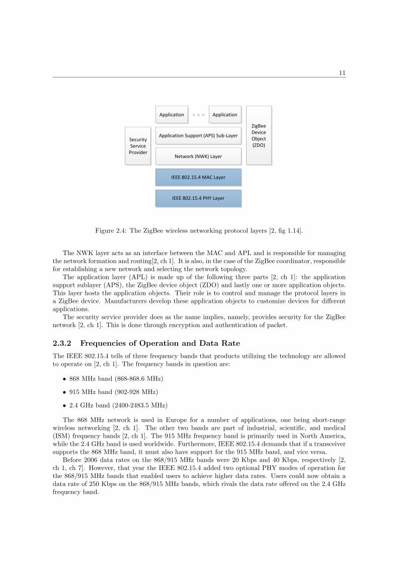
2.3.1 Architecture
The ZigBee network protocol is divided into several layers [2, ch 1]. These layers can be seen in Figure2.4. The bottom two layers, i.e. the PHY and MAC layers, are defined by the IEEE 802.15.4 standardand adopted by the ZigBee networking protocol. The ZigBee standard defines the remaining layerswhich are the networking, application and security layers.
11
Application Support (APS) Sub-Layer
Network (NWK) Layer
IEEE 802.15.4 MAC Layer
IEEE 802.15.4 PHY Layer
ZigBee Device Object (ZDO)
SecurityService
Provider
ApplicationApplication
Figure 2.4: The ZigBee wireless networking protocol layers [2, fig 1.14].
The NWK layer acts as an interface between the MAC and APL and is responsible for managingthe network formation and routing[2, ch 1]. It is also, in the case of the ZigBee coordinator, responsiblefor establishing a new network and selecting the network topology.
The application layer (APL) is made up of the following three parts [2, ch 1]: the applicationsupport sublayer (APS), the ZigBee device object (ZDO) and lastly one or more application objects.This layer hosts the application objects. Their role is to control and manage the protocol layers ina ZigBee device. Manufacturers develop these application objects to customize devices for differentapplications.
The security service provider does as the name implies, namely, provides security for the ZigBeenetwork [2, ch 1]. This is done through encryption and authentication of packet.
2.3.2 Frequencies of Operation and Data Rate
The IEEE 802.15.4 tells of three frequency bands that products utilizing the technology are allowedto operate on [2, ch 1]. The frequency bands in question are:
• 868 MHz band (868-868.6 MHz)
• 915 MHz band (902-928 MHz)
• 2.4 GHz band (2400-2483.5 MHz)
The 868 MHz network is used in Europe for a number of applications, one being short-rangewireless networking [2, ch 1]. The other two bands are part of industrial, scientific, and medical(ISM) frequency bands [2, ch 1]. The 915 MHz frequency band is primarily used in North America,while the 2.4 GHz band is used worldwide. Furthermore, IEEE 802.15.4 demands that if a transceiversupports the 868 MHz band, it must also have support for the 915 MHz band, and vice versa.
Before 2006 data rates on the 868/915 MHz bands were 20 Kbps and 40 Kbps, respectively [2,ch 1, ch 7]. However, that year the IEEE 802.15.4 added two optional PHY modes of operation forthe 868/915 MHz bands that enabled users to achieve higher data rates. Users could now obtain adata rate of 250 Kbps on the 868/915 MHz bands, which rivals the data rate offered on the 2.4 GHzfrequency band.

12
Transceivers operating on the 2.4 GHz ISM band may support 868/915 MHz bands, but it is notrequired by the IEEE 802.15.4 [2, ch 1]. The 2.4 GHz band has room for a total of 16 channels, whichis more than the other two bands have together [2, ch 1]. The 915 MHz band has 10 channels (notcounting the optional channels), while the 868 MHz band only has room for one channel.
Many manufacturers choose to develop their transceivers for the 2.4 GHz band because it isaccepted worldwide [2, ch 1]. There are of course other reasons for this decision such as the maximumdata rate that it enables and the number of channels available [2, ch 1]. However, all transceivers thatfollow the IEEE 802.11b standard operate on the 2.4 GHz band, making it a very crowded frequencyband [2, ch 1]. Also, the lower the frequency band is, the better the signal penetrates walls andvarious objects [2, ch 1, ch 7]. For these reasons some may find the 868/915 MHz bands a better fit.
2.3.3 Device Types
The IEEE 802.15.4 standard defines two types of devices [2, ch 4]: full-function devices (FFDs) andreduced-function devices (RFDs). An FFD can perform all the duties described in standard and canaccept any role in the network. An RFD, on the other hand, is more limited. For example, while aFFD can communicate with any other device in the network, a RFD can only talk with an FFD.
2.3.4 Device Roles
There are three roles that a ZigBee network node can assume: the ZigBee Coordinator (ZC), theZigBee Router (ZR) and lastly the ZigBee End-Device (ZED) [2, ch 4]. The ZC and ZR are bothFFDs while the ZED is a RFD.
The Coordinator is the only device that can form networks [2, ch 4]. If the network is secure theZC must be present to add new nodes to the network [2, ch 4]. This has to do with the fact that theZC contains the networks Trust Center. Only the Trust Center can decide whether or not to granta node access to the network. On the other hand, if the network is unsecure, once the network isformed the ZC is basically a router.
The ZigBee Router is used to enhance the mesh in the network [2, ch 4]. Routers can extend therange of the network and increase its reliability [2, ch 4]. ZRs like the ZC route packets within thenetwork [2, ch 4]. They are also permitted to grant other nodes access to the network (unsecure).However, in the case of a secure network, the ZR still needs to ask the ZC for permission beforegranting access to the network.
The ZigBee End-Device is a node that often is battery-operated and therefore has the ability toenter sleep-mode during network inactivity [2, ch 4]. Normally, when a ZED wakes up, it transmitsits data, poll its parent to see if any messages are waiting for it and then returns to sleep-mode whilewaiting for its next active state.
2.3.5 Network Topology
The network formation is managed by the ZigBee networking layer [2, ch 7]. There are two types ofnetworking topologies defined by the IEEE 802.14.5 [2, ch 7]: star and peer-to-peer.
In the star topology nodes in the network communicate strictly with the PAN (Personal AreaNetwork) coordinator [2, ch 7]. In the case that nodes want to send data to each other, the coordinatortakes on the role of a network router.
In a peer-to-peer topology devices can communicate directly with each other if they are placedclose enough together to establish a successful communication link [2, ch 7]. Any full-function device(FFD) can assume the role of the PAN coordinator [2, ch 7]. One way to decide which device willbe the PAN coordinator is to pick the first FFD that has the need to transmit data, i.e. breaks radiosilence [2, ch 7]. Another way would be to have a designated FFD device that always takes on the

13
role of the PAN coordinator. A peer-to-peer network can take on different shapes [2, ch 7]. This isdone by defining restrictions on the devices that can communication with each other. If there is norestriction, the peer-to-peer network has what is called a mesh topology [2, ch 7]. Another form ofpeer-to-peer network ZigBee supports is a tree topology [2, ch 7]. In this case, a ZigBee coordinator(PAN coordinator) forms the initial network. ZigBee routers act as the branches. One of their maintasks is to route messages. ZigBee end-devices act as leaves of the tree and do not participate inmessage routing.
2.3.6 ZigBee and IEEE 802.15.4 Communication Basics
2.3.6.1 CSMA-CA
A channel access mechanism is needed when multiple devices use the same frequency channel [2, ch7]. The mechanism included in the IEEE 802.15.4 goes by the name of Carrier Sense Multiple Accesswith Collision Avoidance also known as CSMA-CA [2, ch 7][14, ch 1]. It performs a clear channelassessment (CCA) whenever a device wants to transmit data [14, ch 1]. This basically means that itchecks whether or not the channel is free. After finding that the channel is clear the device begins totransmit its own data. The decision to declare a channel clear or not can be based either on measuringthe spectral energy in the frequency channel of interest or detecting the type of the occupying signal[14, ch 1].
Before a device starts to transmit a signal, it first enters receive mode to detect and estimate thesignal energy level in the desired channel [14, ch 1]. This act is know as an energy detection (ED). Thereceiver never decodes a detected signal or tries to determine whether or not it is an IEEE 802.15.4signal [14, ch 1]. When the receiver performs an ED, it is merely interested in the energy level of thesignal.
There is an alternative method to declaring a frequency channel clear or not, namely a carriersense (CS) [14, ch 1]. Contrary to the ED, the receiver is interested in the type of the signal occupyingthe channel [14, ch 1]. If it is an IEEE 802.15.4 signal, the device may decide to consider the channelbusy even if the signal energy is below the user-defined threshold.
Regardless of the method being used, if the channel is declared busy, the device will back off arandom period of time and performs a new scan of the channel [14, ch 1]. The maximum number ofretries is configurable [14, ch 1].
2.3.6.2 Beacon-Enabled vs. Nonbeacon Networking
There are two basic concepts for channel access, namely contention based and contention free [14, ch1]. Contention-based channel access is when multiple devices compete for a transmission slot on thesame frequency, by using the CSMA-CA mechanism [14, ch 1]. In the contention-free channel access,the PAN coordinator assigns individual time slots for each of the devices in the network [14, ch 1].This is known as a guaranteed time slot (GTS). Due to these time slots, a transmitting device knowswhen the channel is clear without using the CSMA-CA mechanism.
There is one primary criterion that needs to be met in order for the PAN coordinator to be able toprovide a GTS [14, ch 1]. The PAN coordinator needs to synchronize with all devices in the network.This is done by transmitting a beacon signal that synchronizes the clocks of the nodes in the network.This is called a beacon-enabled PAN. Having a beacon-enabled PAN comes with a price, namely, alldevices in the network must wake up on a regular basis, listen for the beacon, synchronize their clock,and go back to sleep [14, ch 1]. This results in unnecessary power usage for devices that wake up onlyto synchronize and not perform any other task while active. Therefore, the battery life of a devicein a beacon-enabled network is normally less than the battery life of a device deployed in a networkwith no beaconing.

14
A nonbeacon network is a network with a PAN coordinator that does not transmit beacons, i.e.an unsynchronized network [14, ch 1]. This leads to an absence of GTSs and therefore contention-freeperiods. Nodes in nonbeacon networks wake up less, and in so doing prolong their battery life [14, ch1].
2.3.7 ZigBee Self-Forming and Self-Healing
As mentioned in Subsection 2.3.5, a ZigBee network starts to take form as soon as the devices becomeactive. ZigBee networks are considered self-forming due to the fact that no additional supervision isneeded to establish a network [2, ch 7][14, ch 1].
When a mesh network is formed, there is normally more than one way to route a message betweendevices [2, ch 7]. The most optimized route is selected with the help of a route discovery [2, ch 7]. Aroute discovery is basically a broadcast from the initializing device that spreads across the network[2, ch 7]. When it finally reaches the target device a total path cost has been accumulated [2, ch 7].This total path cost is based on the total number of hops (links) and their individual path cost. Theindividual path cost of a link is a reflection of the quality of a link (if retries were needed between twonodes). Because of the nature of route discoveries the target device will most likely receive multiplealternative routes [2, ch 7]. The best route, i.e. the route with the lowest total path cost, will beselected and a reply will be sent along that route back to the initializing device [2, ch 7]. During thisreply all affected devices update their routing tables with the new route [2, ch 7].
Sometimes routes break. It might be because obstacle blocks the message route or maybe a routerstops functioning due to power failure [2, ch 7]. In any case, a new route discovery is called upon [2,ch 7]. This is an example of the self-healing characteristic of a ZigBee mesh network.
In an ad hoc network, such as ZigBee, some wireless nodes are willing to forward data for otherdevices [2, ch 7]. The route is selected dynamically based on the network connectivity [2, ch 7]. Ifthe node condition changes, it might be necessary to perform a route discovery in order to heal thenetwork [2, ch 7]. Other networking technologies are not as agile with their infrastructure in place,together with some designated devices for message routing [2, ch 7].
2.4 CPR3 Transport Protocol
The CPR3 transport protocol has two types of over-the-air frames. It all depends on the direction ofthe communication.
2.4.1 Structure for Messages to CPR3s
A message consists of four bytes. Each byte holds an 8-bit ASCII character. The first byte containsthe character # which tells the CPR3 that it is the start byte. This is followed by the second bytethat contains information about which setting to change. The characters and their descriptions canbe found in Table 2.3. The third byte contains the settings value in the form of an ASCII character.They range from the character for space (minimum value equal to zero) all the way up to the charactera (maximum value equal to a hundred). The last byte contains the CR (Carriage Return) characterwhich lets the CPR3 know that it is the end of the message.
2.4.2 Structure for Messages from CPR3s
Messages from the CPR3 all have the same basic format but their length varies depending on themessage type. The first byte contains 0x01 which corresponds to SOH (Start Of Heading) in ASCII.The second byte holds the length of the message not counting the two first bytes. Next in the messageis the command byte with its five possible commands as seen in Table 2.4. The consequent section,

15
Table 2.3: Commands that are accepted by a CPR3.
Command Description
R SensitivityV VolumeB Display light enable/disableL Display light level
Table 2.4: Commands that are issued by a CPR3.
Command Description
0x15 Radar reading0x16 Sensitivity0x25 CPR3 movement0x28 Volume0x29 Display light status
contain either radar readings or a settings value, varies in length. If the message contains a settingschange the sections size is one byte but if it contains radar readings the size would be two bytes. Thefinal byte is for storing a checksum calculated by the CPR3 before transmission.

16

Chapter 3
CiTerm
This section contains information about the application by the name of CiTerm.
3.1 Use-Case Scenario
The CiTerm application is meant to enable remote threat assessments conducted by police and/ormilitary forces. First, one or more CPR3s are placed on desired locations. Figure 3.1 depicts ause-case for the application. A normal scenario would be to place the devices against walls of roomsthat need searching. Then, for example, a police officer starts the CiTerm application on his or hercell phone. By having the application on a cell phone, the officer is free to move around without anyhindrance from wires or power cords. He or She performs a quick search for any CPR3 devices withinBluetooth range of the cell phone. He or she then connects to the desired CPR3 devices. The officercan now, with the help of the CiTerm application, obtain a complete picture of the situation. Theapplication also gives the operator some control over the connected CPR3s. In other words, if anysettings need adjusting, it can be done remotely.
3.2 Software Requirements
In this section the requirements for the CiTerm application are defined. They are divided into twocategories which are functional and non-functional requirements. The functional requirements can befound in Table 3.1 while the non-functional requirements can be found in Table 3.2.
3.3 Application Design
When launching the CiTerm application, it instantiates a TabDialog object that inherits from theQDialog class. This TabDialog object instantiates three tab objects namely OverviewTab, SettingsTaband SearchTab. These tab objects all inherit from the QWidget class. Each of the tabs has its ownlayout specific for the functionality offered by the tab.
The RadarDevice class was defined to help with the CPR3 data management within the CiTermapplication. Every time a CPR3 connection is made, an instance of the class is created and storedin a vector. An object holds a reference to a device specific communication socket. Also stored inthe RadarDevice object is the Bluetooth address, the name of the CPR3 together with all relevantsettings.
17

18
User
CiTerm Application
«uses»
Change settings
«extends»
View sensorinformation
«uses»
«uses»
Disconnect CPR3
«uses»
Search for CPR3Connect CPR3
Change brightness
Change sensitivity
Change volume
«extends»
«extends»
Figure 3.1: A use-case for the CiTerm application.
Table 3.1: A collection of the functional requirements.
ID No. Requirement
1 The application shall be able to display unconnected CPR3s operating within Blue-tooth range of the cell phone.
2 The application shall not display unconnected Bluetooth devices operating withinBluetooth range of the cell phone, other than the devices mentioned in requirementNo. 1.
3 The application shall be able to establish a Bluetooth connection to a CPR3 withinBluetooth range of the cell phone.
4 The application shall be able to close the connection established according to require-ment No. 3.
5 The application shall be able to maintain a maximum of six Bluetooth connectionsat the same time.
6 The application shall be able to change the volume setting on a selected CPR3. Onlyconnected CPR3s can be selected.
7 The application shall be able to change the sensitivity setting on a selected CPR3.Only connected CPR3s can be selected.
8 The application shall be able to change the brightness setting on a selected CPR3.Only connected CPR3s can be selected.
9 The application shall be able to display the detection status of all the connectedCPR3s.
10 The application shall run on the Windows Mobile 6.0 platform.
Table 3.2: A collection of the non-functional requirements.
ID No. Requirement
11 The application shall be built with the Qt framework.

19
0010 0011 0000 0010 0001 01000001 0101 0001 0110
START COMMAND VALUE CHECKSUM
0011 0100
LENGTH
Figure 3.2: An example of a message from a CPR3 containing radar data.
Upon establishing a Bluetooth connection with a CPR3, the application sends a message that tellsthe radar device to start sending radar readings and notifications regarding settings back to CiTerm.That message consists of the word connect (all uppercase letters) followed by \n, commonly knownas a character sequence for newline. When the CPR3 receives this message it sends several messagesback to CiTerm. These messages each contain a CPR3 setting. This is done so that CiTerm canacquire the starting values for each CPR3 setting. This action is a onetime occurrence. Normally,messages containing this type of data are only sent when a user, on either side, manually changesa setting. After the initial message passing between the devices, the CPR3 starts to periodicallysend radar readings back to CiTerm. Figure 3.2 depicts an example of such a message as it reachesCiTerm’s application layer. The message begins with a start byte which contains the binary sequencecorresponding with the hexadecimal number 0x01, also known as the ASCII character SOH. Thesecond byte contains the length of the message - or rather, the length of the rest of the message.While the length byte contains a binary sequence equal to the ASCII character 4, the actual sizeof the message is six bytes. The third byte in the message is the command byte. In this exampleit contains the binary sequence equivalent to the hexadecimal number 0x15 which means that themessage contains radar data. Thus far all bytes have been interpreted as ASCII chars by CiTerm.This changes when the application is processing the two bytes containing the radar data. The sixteenbits are interpreted as the lower half of a thirty-two bit integer. The last byte included in the messageis a checksum. In order to verify the integrity of the message, CiTerm compares the received checksumwith a self calculated value. This was just one example of the messages that are sent between CiTermand a CPR3. All message structures, except the initial connect message, can be found in Section 2.4.
Every second, the application iterates over the storage vector while reading each object’s socketinbuffer. If a message is found, its integrity is checked by calculating a checksum and comparingit to the one incorporated in the received message. On a positive integrity check, the data fromthe message is stored in the RadarDevice object. After all the socket inbuffers have been checkedfor received messages, the GUI is updated. Each of the objects stored in the vector contain a boolvariable that basically tells the application which device is showing on the settings tab. While theapplication iterates over the storage vector in order to update all the alert icons on the overview tab,it also checks the visibility bool. CiTerm then updates the relevant GUI components (buttons, labelsetc.) upon finding the visible device. All the interactive Qt components (buttons, spinboxes etc.)used in the CiTerm application are connected, through Qt’s signal and slot mechanism, to differentfunctions depending on the nature of the component. When a component associated with a CPR3setting changes value, a function is called that constructs an update message and subsequently sends itto the device. The message includes information about the changed setting. When the CPR3 receivesthe message, it updates the setting in question. Every time a CiTerm connected CPR3 updates asetting, either through a button push or a message from CiTerm, it sends a confirmation messageback to the application containing the current value. It is worth mentioning that both the CPR3 andthe CiTerm application (if connected) have the same basic need to inform the other one if a setting

20
changes value. This shared behavior caused some problems during the early stages of development.The main problem was update messages bouncing back and forth between the CiTerm applicationand the connected CPR3. The first improvement made to the application was to let CiTerm performa control before updating any Qt components related to CPR3 settings. If the newly received settingdiffers from the one kept in the component, the new value is accepted otherwise it is discarded. Thesecond improvement to CiTerm was to let it perform a control before sending an update message toa CPR3. The message is approved for transmission if its value differs from the value found in thestorage vector, otherwise it is discarded. It is important to understand that these improvements didnot completely remove the problem. However, it did help minimize the risk of it occurring.
3.4 Graphical Interface
The CiTerm application’s functionality is split up onto three tabs. The first tab, with the descriptionlabel Overview, contains a summary of all the connected devices and their status. The second tab,with the description label Settings, lets the user change settings on one of the connected devices. Thethird tab, with the description label Search, lets the user search for deployed unconnected devicesnearby.
The overview tab, seen in Figure 3.3, consists mainly of a list containing all connected CPR3devices. To the left of the device names each CPR3 has a status icon. These icons come in threedifferent colors which are green, yellow and red. A green icon tells the user that the CPR3 does notdetect any movement and that the device itself is still while a yellow icon indicates that the CPR3 ismoving and no readings are dependable. Lastly, the red icon tells the user that the CPR3 is detectingmovement.
The settings tab, seen in Figure 3.3, has many different components but they all have one thingin common, they enable the user to change settings on a connected CPR3. The first thing the userneeds to do is to select the desired device from the drop down menu. When doing this, the applicationupdates the values of the spinboxes, the checkbox and the labels. There are three main settings thatcan be changed and they are as follows: sensitivity, volume and display light. The sensitivity settinghas five different levels and each of them has a designated threshold value. These threshold values,starting with level 1, are: 500, 250, 120, 60 and lastly 30. When changing the level on the sensitivityspinbox the corresponding threshold is shown directly above. If the readings from the CPR3 (displayeddirectly beneath the drop down menu) are higher than the threshold the radar device is detectingmovement. The volume setting has seven levels ranging from 0 (mute volume) up to 6 (max volume).The display light setting has two components which are the spinbox and the checkbox located beneaththe two other spinboxes. The display light spinbox can hold values ranging from 2 up to 100. It isworth mentioning that the checkbox needs to be checked before the display light with its desired levelis enabled. The last component on the tab is the button for disconnecting a CPR3. It works like theother components, i.e. the device selected in the drop down menu is the one that is affected.
The search tab, seen in Figure 3.3, consists of a list and two buttons. The first button is forsearching for nearby unconnected CPR3 devices. The search result is then displayed in the list. Thesecond button is for connecting to a nearby unconnected CPR3. Note that the CPR3’s list entryneeds to be highlighted before pushing the connect button. When the connection is successful thatdevice is automatically removed from the search results.

21
Figure 3.3: The available tabs that are found in the CiTerm application.

22

Chapter 4
ZigBee Suitability Evaluation
First off, ZigBee and Bluetooth have different technology objectives [15]. Bluetooth is targetingmarkets containing short range and mobile products [15]. The IEEE defines its ”Personal OperatingSpace” (POS) to a 10 meter radius and allowing for mobility [15]. At first glance, ZigBee seemed tohave a similar mission statement. However, the ZigBee Alliance adds some statements like low powerconsumption and open standard [15]. The IEEE 802.15.4 standard, which is the foundation of theZigBee standard, also speaks of a 10 meters POS but recognizes the possibility for greater range atlower data rates [15]. At present Bluetooth is the technology responsible for transferring data betweennodes in a CPR3 network. The question that needs answering is whether or not ZigBee is a suitablereplacement technology for Bluetooth. This chapter will focus on some key areas that are importantwhen determining whether or not ZigBee is a viable substitute.
4.1 Range
The transmission range of a ZigBee module has little to do with the ZigBee specification [14, ch5]. What does matter is the transmitter’s output power together with the way the receiver and theantennas are designed [14, ch 5]. Furthermore, the range normally mentioned in product white papersare in terms of clear line of sight [14, ch 5]. It is safely assumed that there was a minimum amountof interference from the environment and naturally no obstacles in the way of the transmissions whenthe companies did their measurements [14, ch 5]. All this makes white papers an uncertain sourceof information when transmission range is concerned. Therefore, the best way to evaluate a ZigBeemodule’s transmission range is to field test it in the desired deployment environment.
4.2 Data Rate
If occasional command messages are excluded from the approximation, then for each node in thenetwork an average of 6 bytes of data per second (48 bps) is to be transmitted. These messages areall destined for the network coordinator. The demands on the data rate are different depending onthe network topology being used. An example of a network configuration can be seen in Figure 4.1.Some of the nodes need to route messages to the coordinator. This increases the demand on the datarate. The node closest to the network coordinator needs to be able to transmitt 18 bytes per second(144 bps). This means that the demand on a network node’s data rate increases linearly when thenumber of nodes that it needs to route messages for increases.
Bluetooth version 1.2 with its guaranteed transmission time-slots has a data rate of 1 Mbit/s (laterversions of the specification have much higher data rates) between the network coordinator and the
23

24
Figure 4.1: An example of a node constellation in a mesh network. The colored node being thenetwork coordinator and the rest being regular devices. The arrows showing the route for radar datato be transmitted.
other (up to) seven network nodes [15]. ZigBee on the other hand uses a CSMA-CA mechanism that isan asynchronous technology [3]. This follows the service policy first come, first served [2, ch 7]. Whentransmission collisions do occur, the transmitting nodes back off a random amount of time [2, ch 7].The number of back offs a node is permitted is configurable [2, ch 7]. All this points to that the datarate should be dependent on the network load i.e. there should be a correlation between the number ofnodes within the network and the amount of data they are transmitting. This correlation has alreadybeen researched by another academic [3]. The experiment configuration he used is depicted in Figure4.2. All devices were placed 1 meter from the network coordinator [3]. Three of the network deviceswere traffic load generators while the forth device had the role of main transceiver [3]. The maintransceiver’s purpose was to continuously send 10000 data packets to the coordinator while the trafficload generators took up bandwidth [3]. The experiment included twelve runs where a combinationof two variables made each run unique [3]. First, the number of active traffic load generators wasgradually increased from zero to three. For each of these steps, three runs where performed, each witha different traffic load. The traffic loads used in the experiment were 10, 50 and 100 kbps [3]. Also, thedevices were all stationary during the experiment [3]. The packet size was 20 bytes and the numberof back offs was set to four together with the back off exponent set to three [3]. The results from theexperiment are reflected in Figures 4.3 and 4.4. The results were as suspected. With the increasingnumber of devices, both the effective data rate and delivery ratio decrease due to the presence ofcollisions and random back offs [3]. Moreover, with the larger traffic load from other devices, both theeffective data rate and delivery ratio were also reduced because the collision possibility increased [3].The required data rate for nodes in a CPR3 star network is 48 bps, much lower than what was usedby the traffic load generators used in the experiments. With this, it is safely assumed that ZigBeewith its CSMA-CA mechanism does support at least four stationary CPR3 nodes in a star or meshnetwork. The results also points to that the network could sustain at least three additional nodeswhich would bring the grand total to seven nodes (excluding the coordinator), the same node numberthat Bluetooth supports.
The same study also revealed that increasing the payload size leads to increased data rate dueto the reduction in overhead [3]. The configuration of the experiment was as above but with onedifference. In this case the traffic load generators were transmitting with a data rate of 100 kbps[3]. The results, i.e. how much the payload size affects the effective data rate, can be seen in Figure4.5. So, is the payload size something that needs changing? Seeing as how seldom messages are sentand their size along with the number of nodes in a standard configured CPR3 network, the answer isno. But this will change as soon as more nodes are introduced to the system and/or the connectednodes begin to take on a highly mobile property. There is a way to slightly improve the bandwidthusage through changing the payload size. This is done by buffering all CPR3 issued messages notcontaining radar data and combining them with a message that does. It would result in a hybridmessage that contains both types of data. This is possible due to the fact that the radar data messagesare transmitted periodically (one message per second). This means that any message that bears aCPR3 setting is at most delayed by one second. The total size of the hybrid message would dependon the number of messages it is replacing, i.e. the number of messages residing in the buffer when

25
Coordinator
Traffic Load Generator
Network Device
Figure 4.2: The configuration of the experiments [3, fig 8].
0
10
20
30
40
1 2 3 4
Effective da
ta ra
te (k
bps)
Number of devices
10 kbps
50 kbps
100 kbps
Traffic loadper device
Figure 4.3: Effictive data rate of CSMA-CA with varied traffic load in a nonbeacon-enabled network[3, fig 11].

26
0
20
40
60
80
100
120
1 2 3 4
Delivery ratio
(%)
Number of devices
10 kbps
50 kbps
100 kbps
Traffic loadper device
Figure 4.4: Delivery ratio of CSMA-CA with varied traffic load in a nonbeacon-enabled network [3,fig 12].
the CPR3 is about to transmit a radar data message. Combining a message carrying a CPR3 settingwith a radar data message will result in a hybrid message 8 bytes in size. This means that it couldbe possible to reduce at least 3 bytes of overhead per constructed hybrid message. These reductionsoriginate from the fact that there will not be a need for more than one start byte, one length byteand one checksum byte per hybrid message.
Another interesting fact about ZigBee networks is that they degrade when comprising of an in-creasing number of ZigBee end devices [3]. Moreover, the delivery ratio also degrades when there aremore instances of mobility within the network (in highly mobile scenarios) [3]. Furthermore, com-paring to the AODV routing results, when all nodes are capable of routing (node homogeneity in thenetwork), reveals a significant difference in routing performance [3]. A ZigBee network using AODVrouting has a much higher delivery ratio in highly mobile scenarios than a node heterogeneous ZigBeenetwork [3]. Also, it is revealed that ZigBee end devices tend to perform worse than ZigBee routersin both sending and receiving packets, since the end devices incur much overhead in associating withnew parents when there is network mobility [3]. On the other hand, ZigBee router typically sufferless packet loss when there are intensive amount of mobility in the ZigBee network, yet the additionalservice overhead of ZigBee (such as association with children devices) still degrade the performanceof ZigBee routers in almost all scenarios [3]. So, the need for node homogeneity in the network, withfull function devices, not only originates from the fact that it makes the network more flexible andincreases the chance of network stability through self-healing, but also offers better performance inthe terms of data ratio and delivery ratio [3].
4.3 Network Latency
The low-latency application that is going to run on the network coordinator should get radar dataevery second from each of the nodes connected to the network. The received data should not be olderthan a few seconds. There are two main factors that affect the network latency in a CPR3 ZigBee

27
0
20
40
60
80
100
120
140
1 2 3 4
Effective da
ta ra
te (k
bps)
Number of devices
20 bytes
60 bytes
102 bytes
Data payload(MSDU)
Figure 4.5: Effictive data rate of CSMA-CA with varied data payload size in a nonbeacon-enablednetwork [3, fig 13].
network. These factors are node movement and network traffic [14, ch 3]. If a node moves aroundenough so that a desired transmission route breaks, a route discovery is called on [14, ch 3]. Thisroute discovery is broadcasted across the network and in so doing halts any other transmissions withinthe network [14, ch 3]. The time a route discovery takes is dependent on the number of nodes in thenetwork and their constellation [14, ch 3]. As previously mentioned, the second thing that determinesthe network latency is the amount of network traffic [14, ch 3]. That means that the latency is affectedby the number of nodes within the network together with the traffic these nodes generate. There isno network latency estimation that can be done straightly from examining the ZigBee specification.The only way is to run simulations and/or field tests and from that come to a conclusion whether ornot the network latency is acceptable.
4.4 Power Profile
All network devices are mobile and therefore battery powered. Because of this, power consumptionbecomes an important issue. Bluetooth devices are constantly alert for available networks for themto join [15]. To do that they have to be awake [15]. The power profile is ”always on” to maximizethis ad hoc networking functionality with days of battery life and regular recharging required [15].ZigBee has been developed specially to permit low power consumption and years of battery life [2, ch1][15]. An end device (ZED) on a ZigBee network does not need to keep in constant contact with theparent to remain on the network [2, ch 4]. It has the option to enter sleep mode in order to conserveenergy which is desirable in some cases [2, ch 4]. A CPU interrupt is triggered (by a switch, timeretc.) causing the radio to wake up [2, ch 4]. It takes approximately one millisecond for the node tocomplete this process [2, ch 4]. Upon completion, it then sends its message (if needed) to the parent(ZR) and returns to sleep after polling the parent for messages [2, ch 4]. The parent has the ability tobuffer messages for sleeping children, delivering them when the children wake up [2, ch 4]. However,the message is not buffered forever [2, ch 4]. The messages are kept a maximum of seven seconds
28
(may vary depending on which ZigBee stack is used) before they are discarded. There is a way towake a sleeping child node upon receiving a valid ZigBee packet [2, ch 4]. However, if a radio is awakeenough to decode a signal, it is awake. This means that it is consuming full power which would bearound 20-23 mA (may vary depending on the silicon vendor) [2, ch 4]. Sadly, ZigBee’s power savingfeature is not relevant for this application. The dynamic nature of the application forces all the nodesconnected to the ZigBee network to be routers (ZR). There is no way of knowing which node will bean end device and which node needs to route messages. This means that ZigBee has lost its upperhand against Bluetooth when it comes to power consumption. It all boils down to the transmitter’soutput power along with the design of the modules.

Chapter 5
Conclusions
This chapter is divided into three parts, each representing a vital area of the study. The first partdiscusses the CiTerm application while the second part summarizes some thoughts about the Qtframework. The last part presents the findings from the theoretical evaluation regarding the use ofZigBee as a means of sending data between CPR3s.
The CiTerm application meets all the requirements mentioned in Section 3.2. That makes ita successful prototype. However, some minor changes to the system are needed to eliminate theproblem mentioned in Section 3.3. It would be desirable to introduce a more defined master/slaverelationship between the CiTerm application and the connected CPR3s. If the same setting is changedsimultaneously at both ends, which device has the final say as to what the setting should be. In thecase where the device running the CiTerm application would be the master, all incoming messages froma CPR3 would be ignored if CiTerm was awaiting a confirmation message (i.e. a message confirmingthat the CPR3 has updated the setting demanded by CiTerm). It would probably be a good ideato include some sort of sequence number into the transport protocol. This would help to match thetransmitted update message with the received confirmation message. The sequences used by the twosides should not intersect. This would help to eliminate any confusion over the origin of the message(i.e. which device initially demanded the change). Another advantage of using sequence numbers isthat it is very easy to detect messages that were lost during transmission.
Qt is a powerful cross-platform application development framework, and therefore used by manydevelopers. For example, the Linux-based Skype client uses the Qt framework [16]. This makesit easy to support various desktops and distributions, and integrate into the user’s desktop themes[16]. Since the CiTerm application is meant to be used on handheld devices such as smartphones,Qt’s support for such platforms is particularly interesting. The platforms for handheld devices thatNokia’s Qt supports are Symbian, Windows CE/Mobile, Embedded Linux and Maemo [17]. Thereexists several external Qt ports for other platforms but many of them are in the experimental stagesand therefore not relevant. Recent events have made Qt’s future uncertain. Nokia announced thatthey will be adopting Windows Phone as its primary smartphone strategy [18][19]. Microsoft willbe providing its free Windows Phone Developer Tools (Visual Studio 2010, Expression, Silverlightand the XNA Framework) to developers interested in developing for Nokia Windows Phones whileproviding ”guidance” to anyone wishing to port their applications to WP7 [18][19]. This basicallymeans that Qt will not be adapted for Windows Phone 7 APIs. However, Nokia states that Qt willcontinue to be the development framework for Symbian as they are planning to sell around 150 millionmore Symbian devices [18][19]. So to summarize, Qt does not support Android, Windows Phone 7or iOS (also known as iPhone OS). Furthermore, it does not seem that the support will be addedany time soon, if ever. This means that Qt fails as a suitable cross-platform development frameworkfor handheld devices, at least when the CiTerm application is concerned. Therefore, further study is
29

30
needed to find a more suitable cross-platform development framework.Many factors need to be taken into account before a recommendation can be made. Sure, not
everything has to do with the ZigBee specification. A couple of examples would be the transmissionrange of a ZigBee module and its power profile. They both are directly linked to the transmitter’soutput power and module design. This creates a need for individual evaluations of the ZigBee modulesin order to determine their worth. However, a more pressing matter is the impact the route discoveryhas on the network latency along with the network throughput. It would be hard, if not impossible,to determine through a theoretical study. Therefore, the recommendation is to conduct simulationsand/or field tests in order to ensure that route discoveries do not hinder CPR3 data transmissions.The parameters for these tests should be taken from actual CPR3 deployment scenarios in order tohelp make a correct recommendation.

Appendices
31


Appendix A
Development Environment
In this appendix issues related to the development environment are discussed. Subsection A.1 goesthrough all the components needed for the development of a Windows Mobile application. SubsectionA.2 describes the needed steps to configure Qt. Finally, Subsection A.3 presents debug alternativeswhen developing for the Windows Mobile platform.
A.1 Applications and SDKs
Qt comes in different releases [20]. There are releases that contain the complete Qt developmentenvironment and others that only contain the Qt framework. The Qt SDK 2010.01, which is aframework only release, was chosen for the development of the CiTerm application. The obvious choiceof development environment, when working with Windows Mobile applications, is Visual Studio withits extensive emulator support and its powerful remote debugging features [21]. So, Visual Studio2008 was the version selected for the task. Furthermore, Windows Mobile 6 Professional SDK wasalso installed on the development computer. It contains many useful things for developing WindowsMobile 6 applications, such as a collection of emulator images [4]. Also installed on the developmentcomputer was a Qt4 Visual Studio Add-in (version 1.1.3) which helps to configure Visual Studiofor the use of the Qt framework [22]. The last component that was installed on the developmentcomputer was Windows mobile device center 6.1 which helps the computer to synchronize with themobile device [23]. Without this application no remote debugging can take place.
A.2 Qt Related Issues
An early design decision was if Qt should be configured for dynamic or static linking. The firstoption, dynamic linking, basically means that the application executable will be distributed alongsideneeded Qt DLLs [24]. The second option, static linking, would mean that the application would bedistributed such that all necessary files are built into the executable [24]. This would make handlingthe application easier when not having to worry about any separate Qt DLLs [24]. Since there wereno immediate advantages with dynamic linking, the decision was made to go with static linking.
Static linking is achieved by executing three commands in the Visual Studio 2008 CommandPrompt [25]. The reason why it needs to be this particular command prompt is because it makes surethat all the environment variables for the compiler are found [25]. The first command line containssome flags that might need some explaining. The static flag basically says to create and use static Qtlibraries [25]. The platform flag says what operating system and compiler the developer is buildingon [25]. And lastly, the xplatform flag says what operating system and compiler the developer is cross
33

34
Table A.1: Emulator images that are included in the Windows Mobile 6 Professional SDK [4].
Name Resolution
Windows Mobile 6 Classic 240x320 pixels (96 dpi)Windows Mobile 6 Professional 240x320 pixels (96 dpi)Windows Mobile 6 Professional Square 240x240 pixels (96 dpi)Windows Mobile 6 Professional Square QVGA 320x320 pixels (128 dpi)Windows Mobile 6 Professional Square VGA 480x480 pixels (192 dpi)Windows Mobile 6 Professional VGA 480x640 pixels (192 dpi)
compiling to [25]. Next command line updates the PATH, INCLUDE and LIB paths to point to thecorrect resources for the target platform [25]. And finally, the last command line builds Qt [25].
1. C:\Qt\2010.01\qt>configure -static -platform win32-msvc2008 -xplatform wincewm60professional-msvc2008
2. C:\Qt\2010.01\qt\bin>setcepaths wincewm60professional-msvc2008
3. C:\Qt\2010.01\qt>nmake
A.3 Debug Alternatives
There are two primary methods to debug a Windows Mobile application, either by using a WindowsMobile emulator or remotely on the target device [21][26].
Microsoft has released numerous SDKs containing very practical emulator images [4]. All of themcan be found on MSDN and are free of charge [4]. There is one minor annoyance regarding Microsoft’semulator images. Instead of naming the emulators by the OS along with the resolution of the graphicsdisplay, many are named by the OS along with an acronym that describes the dimensions [4]. TableA.1 lists the emulator images that are included in the Windows Mobile 6 Professional SDK alongwith their display resolution. In order to use the emulator images from the SDKs, some minorconfigurations of Visual Studio are needed. In VS, under configuration manager, the active solutionplatform needs to be set to Windows Mobile 6 Professional SDK (ARM4I) [26]. This will enablethe selection of the SDK emulators for debug purposes. The only thing that remains is to select thecorrect emulator and start debugging.
Debugging on a remote device is a very powerful method of testing an application. In many waysremote debugging is superior to using an emulator since it enables the use of the device’s hardware.Emulators are practical and fast for debugging the graphical part of an application. However, whenthe communication part of an application needs testing, debugging on the target device is the onlyway to go. The only thing that could pose a small problem is memory shortage. Admittedly, it mightbe a small risk but it is a risk nonetheless. Now, the first thing to do when enabling remote devicedebugging is to connect the device to the computer with a USB cable [27]. Next, start WindowsMobile Device Center and let it synchronize the device with the computer [27]. Finally, in VS, selectWindows Mobile 6 Professional Device from the devices list (same list as the emulator images reside)and push the Connect to Device button [27]. After the connection is successful established, everythingis ready for remote device debugging [27].

Bibliography
[1] G. Bradski and A. Kaehler, Bluetooth Essentials for Programmers. Cambridge University Press,2007, ISBN: 978-0-521-70375-8.
[2] D. Gislason, ZigBee Wireless Networking. Elsevier, 2008, ISBN: 978-0-7506-8597-9.
[3] J.-S. Lee, “An experiment on performance study of ieee 802.15.4 wireless networks,” 10th IEEEConference on Emerging Technologies and Factory Automation, vol. 2, 2005.
[4] Microsoft Corporation, “Windows Mobile 6 Professional and Stan-dard Software Development Kits Refresh,” Website, May 2007.[Online]. Available: http://www.microsoft.com/downloads/en/details.aspx?familyid=06111A3A-A651-4745-88EF-3D48091A390B&displaylang=en [Accessed: 2011-05-14].
[5] ——, “Socket (Windows Sockets),” Website, April 2010. [Online]. Available: http://msdn.microsoft.com/en-us/library/aa916640.aspx [Accessed: 2011-06-03].
[6] ——, “Connect,” Website, April 2010. [Online]. Available: http://msdn.microsoft.com/en-us/library/aa923167.aspx [Accessed: 2011-06-03].
[7] ——, “Send,” Website, April 2010. [Online]. Available: http://msdn.microsoft.com/en-us/library/aa923132.aspx [Accessed: 2011-06-03].
[8] ——, “Recv,” Website, April 2010. [Online]. Available: http://msdn.microsoft.com/en-us/library/aa922642.aspx [Accessed: 2011-06-03].
[9] ——, “Close,” Website, April 2010. [Online]. Available: http://msdn.microsoft.com/en-us/library/aa917514.aspx [Accessed: 2011-06-03].
[10] J. Blanchette and M. Summerfield, C++ GUI Programming with Qt 4, 2nd ed. Prentice Hall,2008, ISBN: 0-13-235416-0.
[11] L. Knoll, “Nokia to acquire Trolltech,” Website, January 2008. [Online]. Available:http://labs.qt.nokia.com/2008/01/28/nokia-to-acquire-trolltech/ [Accessed: 2011-06-05].
[12] Nokia Corporation, “Signals & slots,” Website. [Online]. Available: http://doc.qt.nokia.com/latest/signalsandslots.html [Accessed: 2011-06-05].
[13] ——, “Layout management,” Website. [Online]. Available: http://doc.qt.nokia.com/latest/layout.html [Accessed: 2011-06-05].
[14] S. Farahani, ZigBee Wireless Networks and Transceivers. Elsevier, 2008, ISBN: 978-0-7506-8393-7.
35

36
[15] N. Baker, “Zigbee and bluetooth strengths and weaknessess for industrial applications,” Com-puting & Control Engineering Journal, vol. 16, 2005.
[16] Nokia Corporation, “Skype,” Website. [Online]. Available: http://qt.nokia.com/qt-in-use/story/app/skype/ [Accessed: 2011-06-05].
[17] ——, “Supported platforms,” Website. [Online]. Available: http://developer.qt.nokia.com/wiki/Platform Support [Accessed: 2011-06-05].
[18] S. Elop and S. Ballmer, “Open Letter from CEO Stephen Elop, Nokia and CEO SteveBallmer, Microsoft,” Website, February 2011. [Online]. Available: http://conversations.nokia.com/2011/02/11/open-letter-from-ceo-stephen-elop-nokia-and-ceo-steve-ballmer-microsoft/[Accessed: 2011-05-14].
[19] P. Kochikar, “Letter to Developers about Today’s News,” Website, February 2011.[Online]. Available: http://blogs.forum.nokia.com/blog/nokia-developer-news/2011/02/11/letter-to-developers [Accessed: 2011-05-14].
[20] Nokia Corporation, “Download Qt, the cross-platform application framework,” Website.[Online]. Available: http://qt.nokia.com/downloads [Accessed: 2011-06-14].
[21] Microsoft Corporation, “Debugging Windows Mobile Applications,” Website,April 2010. [Online]. Available: http://msdn.microsoft.com/en-us/library/bb158521.aspx [Accessed: 2011-06-14].
[22] Nokia Corporation, “Qt Visual Studio Add-in,” Website. [Online]. Available: http://developer.qt.nokia.com/wiki/QtVSAddin [Accessed: 2011-06-14].
[23] Microsoft Corporation, “Description of Windows Mobile Device Center,” Website, November2010. [Online]. Available: http://support.microsoft.com/kb/931937 [Accessed: 2011-06-14].
[24] Nokia Corporation, “Qt Performance Tuning,” Website. [Online]. Available: http://doc.qt.nokia.com/latest/qt-performance.html [Accessed: 2011-06-14].
[25] ——, “Installing Qt for Windows CE,” Website. [Online]. Available: http://developer.qt.nokia.com/doc/qt-4.7/install-wince.html [Accessed: 2011-06-14].
[26] Microsoft Corporation, “What’s New for Developers in Windows Mobile 6,” Web-site, April 2010. [Online]. Available: http://msdn.microsoft.com/en-us/library/bb278115.aspx [Accessed: 2011-06-14].
[27] ——, “Windows Vista Mobile Device Center Step by Step Guide,” Website. [Online]. Available:http://technet.microsoft.com/en-us/library/cc722321(WS.10).aspx [Accessed: 2011-06-14].