a graph-based semantics for uml class and object diagrams
TRANSCRIPT

A Graph-Based Semantics for UML Class and ObjectDiagrams
Anneke Kleppe? and Arend Rensink
[email protected], [email protected] of Computer Science
University of Twente, Enschede, The Netherlands
Abstract. In this paper we propose a formal extension of type graphs with no-tions that are commonplace in the UML and have long proven their worth inthat context: namely, inheritance, multiplicity, containment and the like. We be-lieve the absence of a comprehensive and commonly agreed upon formalisationof these notions to be an important and, unfortunately, often ignored omission.Since our eventual aim (shared by many researchers) is to give unambiguous, for-mal semantics to the UML using the theory of graphs and graph transformation,in this report we propose a set of definitions to repair this omission. With respectto previous work in this direction, our aim is to arrive at more comprehensive andat the same time simpler definitions.
1 Introduction
Software industry is showing an increasing interest in model-driven development. In-deed, we have little doubt that the future lies in higher-level models to take the placeof code, in all but the most performance critical domains. With this trend, however, thequality of those models is of increasing importance. By this we do not mean the qualityof the product being modelled (which obviously is the final consideration) but ratherof the modelling paradigm. Good models may not guarantee good software, but on theother hand, a bad (ambiguous, inconsistent or unclear) model can never be expected toyield a good end product, in particular if the transformation from model to software islargely automatic.
The quality of models is determined by many aspects, among we believe precision,consistency and completeness to be paramount. The precision of a model correspondsto the lack of ambiguity, or in other words, the degree to which the model will beunderstood in exactly the same way by different persons and tools during the softwaredevelopment process. Consistency formally means the existence of an (i.e., at least one)instance, or implementation, of the model, whereas completeness means the inclusionof all relevant aspects, or (in other words) the ability to predict the behaviour of thesystem under all circumstances.
The above “quality criteria” have a clear, universally agreed-upon interpretation inthe world of mathematics. To make the benefits of the mathematical interpretation avail-able for everyday use in the world of software modelling, however, it is imperative that? The research in this paper was carried out in the GRASLAND project, funded by the Dutch
NWO (project number 612.063.408).

there be a translation from the latter to the former; in other words, a formal semanticsof the modelling language. For instance, it is commonly agreed that a natural interpre-tation of (UML-type) diagrams is in terms of graphs — essentially, just nodes withconnecting edges. Indeed, many authors use UML class (and object) diagrams claimingthat they are representations of type graphs. Unfortunately, few provide an actual for-mal underpinning of this claim, or when they do, the semantics covers only a relativelysmall part of UML; for instance, [1, 3, 11, 18]. The most comprehensive is [19], buteven there such basic notions as multiplicities are missing.
We see the absence of a more complete semantics as an important and regrettableomission, but there is little doubt in our minds about the reason for it. Namely, froma purely formal standpoint, there is no challenge at all in providing the necessary def-initions; in particular, they do not give rise to new results, in the mathematical senseof proved theorems. Instead, getting the semantics right is an engineering effort, wherechoices about how to formalise various UML concepts are not dictated by rock-hardmathematical arguments, but rather by a balance between simplicity and expressiveness,between understandability and conciseness. Carrying out this effort requires a knowl-edge and facility with the required mathematical concepts that is outside the scope ofmost software engineers who would otherwise, by strength of their knowledge of themodelling discipline, be ideally positioned for this task.
Like the papers cited above, in this paper we distinguish the type and instance lev-els, or in other words, type graphs and instance graphs. We see a type graph as anintensional definition of a set of instance graphs, namely, those instance graphs forwhich it is a correct type. Type graphs are then enriched with constraints that captureUML concepts such as bi-directional associations, multiplicities, collection types, in-heritance, redefinition of associations, and composition relationships. In this, we havebased ourselves on the (verbal) descriptions in the UML 2.0 specification [14].
In searching for the aforementioned balance between simplicity and expressivenessof the semantics, we have used the following guidelines:
– Instance graphs should be as simple and straightforward as we can make them, ifnecessary at the price of increasing their sizes. In other words, where there is achoice between enriching the formalism (resulting in more concise but more com-plex graphs) or using larger (sub-)graphs to encode complexity, we have tended tochoose in favour of the latter.This consideration has led to the choice of simple, edge-labelled binary graphs,with as only non-standard feature that edges are numbered, and the numbers are(sometimes) used to reflect an ordering.
– Type graphs should be as close to instance graphs as we can make them; the numberof special features or decorations should be minimised.We have achieved this by using the concept of a graph constraint, which is es-sentially a template for a logical formula on top of an ordinary (type) graph. Thenumber of such templates is small but extensible. Apart from this, the only notionthat we have found to be indispensable is that of inheritance: this cannot be formu-lated as a graph constraint, but is captured instead by an explicit partial orderingover the type graph nodes.
2

The remainder of this paper is structured as follows: after providing the basic defi-nitions to set the stage in Section 2, we discuss the graph constraints in Section 3. Weconsider these to be the heart of our contribution. In Section 4 we relate our constraintsto the standardised UML concepts. Finally, in the conclusion (Section 5) we come backto the above considerations and re-evaluate our choices.
2 Basic concepts
UML class diagrams are, in the terminology of this paper, visualisations of models in agraphical format; likewise, object diagrams are visualisations of model instances. Be-fore we can define these concepts formally, we need to introduce a number of auxiliarynotions.
2.1 Names and namespaces
UML is a visual language; its “sentences” are diagrams. However, a major part of anydiagram is still text, and so we need conventions for visualising text inside diagrams.Here we are especially interested in text used to name things; however, let us first recallthe usual (often unspoken) agreements on the visualisation of text.
Formally speaking, any piece of text is a string of letters from some alphabet. For thepurpose of this paper we fix an alphabet Alpha not containing white space characters;then we can visualise any non-empty string in Alpha+ unambiguously. (Note that wecannot visualise the empty string. Of course we can put quote symbols around it, butthen the visualised text is not the actual string but a transformation of it to a non-emptystring — and the transformation needs to be defined with care to make the visualisationunambiguous.)
Within the set of non-empty strings Alpha+, we furthermore assume a fixed set ofnames Name . For most purposes it is sufficient to think of names as words conformingto the usual scheme of a letter followed by any number of letters, digits and (maybe)underscores and other special symbols; however, also the usual operation and constantsymbols used in arithmetic will be names in our sense. In general, one may assumeName to be defined by some regular expression over Alpha .
However, for a practically usable naming scheme this is not yet enough. In manycases it has been shown to be useful to identify things only partially, leaving it up tothe context in which the identification takes place to disambiguate the name. In order totake this into account, we rely on the (well-known) concept of namespace.
Definition 1 (namespace). Let Name be some globally fixed set of names. The set IDof identifiers, and the set NS of namespaces are the smallest sets such that
ID = NS ×NameNS = {>} ∪ ID .
Less cryptically, NS and ID are built up as follows:
– An identifier is a pair 〈ns,name〉 of a namespace ns and a name name;
3

– There is a root or top namespace > ∈ NS ;– For every ns ∈ NS and name ∈ Name , the identifier 〈ns,name〉 is again a
namespace.
For a given identifier id (∈ ID), we use ns(id) (∈ NS ) to denote the name space andname(id) (∈ Name) to denote the name.
To visualise an identifier we use a well-known notation, which is less cumbersomethan the angular brackets: the name space and name are separated by a dot, and thetop namespace is omitted altogether. Thus, 〈ns,name〉 is actually written ns.name . Atthe same time we assume that this dot (which is in Alpha) is not used any element ofName , so as to avoid ambiguity in the notation.
For instance, the identifier a.name.space consists of the name space in the names-pace a.name, which itself is an identifier with namespace a and name name. The iden-tifier a, finally, consists of the name a in the top name space.
In this setup, we can identify things unambiguously by just giving the name, pro-vided that the intended name space is clear, either implicitly or explicitly. This makesfor a more open-ended and flexible naming scheme than relying on globally uniquenames.
2.2 Signatures and algebras
For our definition of model we use the notion of attributed type graph, as defined in[4]. We repeat the definition here; for a discussion see op. cit.. We also need the formalconcept of an algebra, which we likewise repeat here, for the sake of completeness andto introduce the notations.
Definition 2. A data signature is a tuple Sig = 〈Sort ,Oper , type〉, where
– Sort is a set of data sorts;– Oper a set of operation symbols;– type:Oper → Sort+ is a mapping that associates to every operation op ∈ Oper
a non-empty string of sorts type(op) = s0 · · · sn for n ≥ 0, of which the elementss0 · · · sn−1 constitute the parameter sorts of the operation, and sn constitutes theresult sort.
A Sig-algebra is a tuple Alg = 〈Data,Func〉, where
– Data is a set of disjoint carrier sets, one per sort s ∈ Sort , denoted Ds;– Func is a set of functions, one per operation op ∈ Oper , denoted fop;– The type of the functions in Func should be consistent with type, in the sense that
fop :Ds0 × · · · ×Dsn−1 →Dsnwhenever type(op) = s0 · · · sn.
In practice it is typically the case that Sort ,Oper ⊆ ID and Sort ∩ Oper = ∅. Thisguarantees that we can refer to the sorts and operations unambiguously by identifier.For this paper we make the same assumptions.
Note that an operation op with no parameters (i.e., such that |type(op)| = 1) repre-sents a constant value, which in a Sig-algebra is given by fop().
4

2.3 Graphs
One of the core concepts of this paper is that of graphs. We start by repeating the usualdefinition of a directed, multi-sorted graph.
Definition 3 (graph).
– A graph is a tuple G = 〈Node,Edge, src, tgt〉 where Node is a set of nodes, Edgea set of (directed) edges, and src, tgt :Edge→Node are source and target functions,respectively.
– A path through a graph G is a sequence e1 · · · en ∈ Edge+, such that consecutiveedges in the path are connected in the graph, i.e., tgt(ei) = src(ei+1) for 1 ≤ i <n.
– A set of edges E ∈ Edge is cycle-free if there is no path e1 · · · en in G , such thatei ∈ E for all 1 ≤ i ≤ n, and tgt(en) = src(e1). E is a forest if it is cycle-freeand for all e ∈ E, there is at most one e′ ∈ E such that tgt(e′) = src(e).
Note that although this definition does not yet specify node or edge labels, the nodes andedges do have identities. In some circumstances it will be the case that Node,Edge ⊆ID and the identities are actually meaningful to the reader; it then makes sense to in-clude them in a visualisation of the graph. In particular, this is the case for type graphs— see below.
We will use two kinds of graph: instance graphs and type graphs. Both extend thenotion of graph with some further structure. To start with instance graphs: these havean additional labelling function that associates an identifier with every node and edge.Furthermore, edges have indices, which are chosen from the set of natural numbers insuch a way that the combination of source node, index and label together completelydetermine the edge.
Definition 4 (labelled graph). A labelled graph is a tuple IG =〈Node,Edge, src, tgt , ix , lab〉 where 〈Node,Edge, src, tgt〉 is a graph and
– ix :Edge → IN is an indexing function assigning a natural number to every edge;– lab: (Node ∪ Edge)→ ID is a labelling of nodes and edges;– For e1, e2 ∈ Edge , if src(e1) = src(e2), ix (e1) = ix (e2) and lab(e1) = lab(e2),
then e1 = e2.
For a given node n ∈ Node and label a ∈ ID , the set of outgoing edges is defined by
out(n, a) = {e ∈ Edge | src(e) = n, lab(e) = a} .
The indices assigned by the function ix are used for two purposes:
– To distinguish edges. Graphs may have distinct edges going out of the same nodeand bearing the same label, and even going to the same node (sometimes calledparallel edges). These are useful to represent some UML concepts; in particular,ordered associations and bags. The indices serve to distinguish such edges, i.e.,give them their own identity. In fact, as can be seen from the definition, the identityof an edge is completely determined by its source node, index, and label.
5

– To order edges. One of the more powerful UML concepts is that of an orderedassociation; this does not only define a one-to-many relation between objects ofone type to objects of another, but also establishes a local ordering over the set of(target) objects related to a single (source) object. (The ordering is local in the sensethat it is defined with respect to the source object; another source object, or anotherordered association, may contain the same target objects in a different order.)
In contrast to edges, the encoding of node identities is not fixed by the above definition.It should, however, be understood that there is indeed some distinguishing mechanism,apart from the labelling function, that tells nodes apart. On the implementation level,for instance, this mechanism is typically based on memory addresses, or, for nodes inNode ∩Data , by the data value. On the modelling level, the position within a diagramin principle suffices as the distinguishing mechanism. On the other hand, for ease ofreference it is very common to use symbolic names for nodes. Thus, we arrive at agraphical representation of labelled graphs based on the following conventions:
– Nodes are drawn as boxes with inscribed labels. The labels are preceded by a colon(‘:’). In front of a colon, there may either be a symbolic name, which is in factitself an element of Name , but which plays no role in the formal meaning of thegraph and in fact has no counterpart in Definition 4; or, in the case of nodes that areactually data values, the string representation of the data value may be displayed.(We will see below that the label is typically the type, which for data values v ∈Data is given implicitly by type(v).)If a node has either a symbolic name or a data value indicating its identity, thenthere is no objection against having this node occur multiple times in the graphicalrepresentation: these multiple occurrences still represent the same node, withoutambiguity.
– Edges are drawn as arrows with superimposed labels. The labels may be precededby a number representing the edge index, separated from the label by a colon; inparticular, this is necessary if there is more than one outgoing edge with that labeland the numbering is needed to determine an ordering.
– As an important special case, edges pointing to nodes that are explicitly identified,either by data values or by symbolic names, may be represented by inscribed equa-tions of the form “label = id” or “label:Type = id” instead of arrows. Here, label isthe edge label, Type the label of the target node, and id the target node identifier;i.e., either the string representation of some data value or a symbolic name definedby some node label elsewhere in the graph. In either case, id actually stands for anode of the graph.This special equational edge representation is used only if there is a singular out-going edge with the given label; i.e., there are no distinct e1, e2 with src(e1) =src(e2) and lab(e1) = lab(e2). This way, it is never necessary to include edgeindices in the equation.
Labelled graphs are used to represent concrete systems; in other words, they are onthe level of individual programs or object diagrams. An example showing all of thegraphical representation features is given in Figure 1. Here, y and z are symbolic nameshaving no formal meaning within the graph, whereas 10 and “yes” are data values of
6

Fig. 1: Example graphical representation of a labelled graph
type Int and String, respectively, and 88, 45 etc. are edge indices. The graph representedby this figure is formally (though not uniquely) captured by the following tables:
Node lab namen1 A zn2 Cn3 A yn4 A10 Int
“yes” String
Edge src lab ix tgt(n1, nh, 1) n1 nh 1 10(n2, xyz, 45) n2 xyz 45 n1
(n2, kl, 19) n2 p1 19 n3
(n2, abc, 45) n2 abc 45 n3
(n2, abc, 88) n2 abc 88 n4
(n4, n, 8) n4 n 8 “yes”
These tables should be read as follows:
– The first table defines the nodes and their labelling. Note that the node identities n1
through n4 are not part of the graphical representation and hence are not uniquelydetermined by it; instead, they can be picked at random from a pool of node identi-fiers (or, in an implementation, allocated dynamically). The node identities 10 and“yes”, on the other hand, are data values: they are fixed by the graph. The nodelabels are always shown in the graph. The third row captures the symbolic namesintroduced in the graph. These names are not properly part of the graph as it is de-fined in Definition 4, but are used to refer to nodes without relying on their identity— which, as we have seen above, may be randomly chosen. For instance, sym-bolic node names can be used to represent edges as equations written in (a secondcompartment) of a node, rather than as arrows. (Note that this notation is tradi-tionally used for attributes only, but can be extended uniformly and without risk ofconfusion to other types of edges.)
– The second table defines the edges, by listing each edge as a triple of source node,label, and index. Due to the third clause of Definition 4 this indeed uniquely iden-tifies every edge. The source node and label are always part of the graphical rep-resentation; the edge index, on the other hand, may be omitted, in which case (asfor the node identities) it may be chosen at random. The table furthermore lists thefunctions required for edges in Definition 4; clearly, the first three of these merelyselect the appropriate elements from the edge structure, whereas the fourth is takenfrom the graph itself, taking the choice of node identities into account.
7

Fig. 2: Different graphical representations for attributes in labelled graphs
As a further illustration, Figure 2 shows two different ways to depict one and the samegraph, which has a single non-data node with a single String-type attribute. Whereasthe first representation coincides with the usual one and will probably be preferable inpractice, the second notation makes clear that data values are, formally, graph nodes.
2.4 Graph morphisms
With respect to our aim of providing a sound and comprehensive formalisation of UMLconcepts, one aspect is not yet completely covered, namely the fact that node identitiesand edge indices are not uniquely determined by the diagrams. In this sense, the formalinterpretation of the diagrams remains ambiguous.
The reason why we are nevertheless content with this solution is that this ambiguityis not harmful, because the choice in no way matters to the actual meaning. Put differ-ently, it is allowed to abstract away from the precise identities, provided the nodes andedges remain distinguishable. The standard way to formalise this type of argument isby interpreting the structures under consideration — here, our graphs — up to or mod-ulo some equivalence. In this particular case, the standard way to define an appropriateequivalence is through the notion of graph isomorphism.
Definition 5 (graph (iso)morphism). Given two graphs G, H , a morphism from G toH is a pair of mappings f = (fNode :NodeG→NodeH , fEdge :EdgeG→EdgeH) suchthat
– Node and edge labels are preserved: labH ◦ (fNode ∪ fEdge) = labG;– Sources and targets are preserved: srcH◦fEdge = fNode◦srcG and tgtH◦fEdge =
fNode ◦ tgtG
f is an isomorphism if fNode and fEdge are bijective, i.e., provide a one-to-one map-ping between NodeG and NodeH , resp. EdgeG and EdgeH . We write G ∼= H (G isisomorphic to H) to denote that there is an isomorphism from G to H .
It is especially important to realise that (iso)morphisms are not required to eitherrespect node identities or edge indices, symbolic names, or diagram layout. Thus, forinstance, the two graphs in Figure 3 are isomorphic, despite the fact that their edgeindices and symbolic names are different, as is their layouting.
To be even more precise, assuming that the node identities of both graphs are chosensuch that each X-labelled node has identity nX , the following is the fEdge part of the
8

Fig. 3: Different yet isomorphic graphs
isomorphism from the left hand side graph to the right hand side graph of Figure 3:
(xC , abc, 45) → (xC , abc, 18)(xC , abc, 88) → (xC , abc, 7)(xC , qp, 45) → (xC , qp, 93)(xB , kl, 27) → (xB , kl, 2)
In general, we will set up all our definitions in such a way that they are insensitive toisomorphism; (meaning that a property holds for a graph G if and only if it holds for allH ∼= G).
For one particular purpose we will later on strengthen the requirements on mor-phisms, in such a way that the ordering on edge indices is sometimes required to bepreserved; namely, when we use the index to reflect an ordering over the edges them-selves.
2.5 Type graphs
For purposes of documentation, structuring and correctness, it is common to impose adiscipline over labelled graphs, comparable to the grammar of programming languages,or more to the point here, comparable to a class diagram. In particular, we use a typegraph to impose local constraints on the allowed labels and connections between edgesand nodes, and associated constraints to impose other, more sophisticated or less local,properties.
Definition 6 (type graph). A type graph is a tuple TG =〈NType,EType, src, tgt , inh〉 where
1. NType ⊆ ID is a set of node types and EType ⊆ ID a set of edge types;2. 〈NType,EType, src, tgt〉 is a graph, with NType as node set and EType as edge
set, such that src(e) = ns(e) for any e ∈ EType;3. inh ⊆ NType×NType is a reflexive partial ordering relation expressing that some
node types inherit from others. (Reflexivity here means that T inh T holds for allnode types T ∈ NType.)
We typically use capital letters (T,E) to range over node and edge types. We also useext ⊆ inh to denote extension, which is a sub-relation of inheritance, defined such thatX ext Y if and only if (i) X inh Y and (ii) there is no Z with Z /∈ {X, Y } andX inh Z inh Y . (Formally, ext is the direct predecessor relation inside inh , or inother words, the smallest relation generating inh .)
9

Fig. 4: Example type graph
The condition on the source function of edges (clause 2 in the definition) states thatthe source type of an edge is at the same time its name space. Since edge types areidentifiers and identifiers are pairs of names and namespaces(Definition 1) , it followsthat edge types are uniquely determined by their source type and name. This setupallows us to use edge types with the same name, but only for distinct source types —which is consistent with the situation in most, if not all, object-oriented paradigms.
Also note that inh is a partial order, but not necessarily a forest: this implies that anode type can extend more than one other node type (in common terminology, our typegraphs support multiple inheritance). At the same time, the partial order nature of inhimplies that there can be no inheritance cycles.
For “node type” in the definition above, one may for most purposes read “class;” theonly difference is that the node types typically include data sorts. We say that TG buildson a signature Sig (or is a Sig-type graph), if Sort ⊆ NType. The operations of Sigare not included in the type graph. In this paper we assume that there is no inheritances ext t with s ∈ Sort and no edge e with src(e) ∈ Sort .
A visual representation of a type graph can be given by drawing every node type asa box with the type identifier inscribed, every edge type as a “normal” arrow with theedge name as label, and every extension (i.e., from ext , not inh!) as an unlabelled arrowwith triangular arrow head. Figure 4 shows an example type graph. This is very closeto the traditional class diagram view, except that the data sorts are not treated as specialcases (i.e., data type attributes are not distinguished from associations). Formally, thistype graph is captured by the following tables of nodes and edges:
2.6 Typing and instance graphs
The meaning of a type graph is defined by the set of its (correctly typed) instances.1 Theidea is that the instances of a type graph TG are labelled graphs with labels chosen fromthe types of TG , and consistent with the graph structure of TG modulo inheritance. Toformalise it, we use the following auxiliary notation for arbitrary nodes n and nodetypes T , resp. edges e and edge types E:
n:T :⇔ lab(n) inh T
e:E :⇔ lab(e) = E .
1 Strictly speaking, the meaning is defined by the category of instances and valid morphisms: asmentioned above, in one case we need to impose additional requirements on the morphismsrather than the graphs.
10

Fig. 5: Instance graph for the type graph in Figure 4
In words, n:T expresses that the label of the node n (in the instance graph under consid-eration) is a node type that inherits from T . Note that it follows that, for a given n, therecan easily be more than one node type T such that n:T , ranging from T = lab(n) to allgeneralisations of T . On the other hand, in case of edges, e:E expresses that lab(e) isexactly the edge type E.
Definition 7 (instance graph). Let TG be a type graph. A labelled graph IG is typedby TG , or an instance graph of TG , if for every node n ∈ Node and every edgee ∈ Edge:
– lab(n) ∈ NType and lab(e) ∈ EType;– src(e):src(lab(e)) and tgt(e):tgt(lab(e)).
The set of instance graphs of TG is denoted Inst [TG ] (but see Footnote 1).
For instance, the labelled graph in Figure 1 is not an instance graph of the type graph inFigure 4, since it contains several edge labels that are not present in the type graph. Anexample of an instance graph for Figure 4 is shown in Figure 5.
3 Constraints
The concepts introduced in the previous section are, in the sense of existing graph the-ory, straightforward; in fact, the only non-standard concepts are the structure we havechosen for identifiers, and the fact that we are using indexed edges in labelled (instance)graphs. In this section, we introduce a way to enrich type graphs, and so constrain theset of valid instance graphs, in ways that formalise the concepts found in UML.
First of all, we give a general definition of a constraint set over a graph; then, wedefine a series of special types of constraints tuned towards UML concepts.
Definition 8 (graph constraint). Let TG be a type graph. A constraint set over TG isa tuple 〈Con, sat〉 where
– Con is a set of graph constraints;– sat ⊆ Inst [TG ]× Con is a satisfaction relation over the instances of TG .
We denote IG sat c to denote that an instance graph IG satisfies a constraint c.
11

Table 6: A classification of constraints
Category ConstraintsNode type AbstractnessAssociation Bidirectionality, Multiplicities, Indexing, UniquenessContainment Acyclicity, UnsharednessSpecialisation Subsetting, Redefinition, UnionGeneral OCL
This definition only specifies that a graph constraint is something for which there existsan interpretation, expressed in terms of the graphs that satisfy the constraint. The inter-pretation is embodied in the satisfaction relation, sat . The real question is how sat isdefined. By combining type graphs with a constraint set, we arrive at the concept of amodel, which is our equivalent to a UML class diagram.
Definition 9 (model). A model is a pair Mod = 〈TG ,Con〉 where
– TG is a type graph;– Con is a constraint set over TG , consisting of constraints of the types listed below.
We say that a labelled graph G is an instance of Mod if G ∈ Inst [TG ], and G sat cfor all c ∈ Con .
The main contribution of this work, apart from the selection of the appropriate type andinstance graph definitions, lies in the definition of a number of useful graph constraint“templates” and the corresponding satisfaction relations. The constraints can be sub-divided into a number of categories, listed in Table 6. The constraints are collected inTable 17.
3.1 Abstractness constraints
A fairly common constraint is that a given class in a class diagram is abstract, meaningthat it may have no direct instances; instead, only proper subclasses can be instantiated.In terms of type and instance graphs, this means that the node type may not itself beused as a label.
Definition 10 (abstractness constraint). Let TG be a type graph. An abstractnessconstraint over TG is a predicate abstract(T ) where T ∈ NType is a node in TG .Satisfaction is defined for all G ∈ Inst [TG ] by
G sat abstract(T ) :⇔ @n ∈ NodeG . lab(n) = T .
Figure 7 shows an example of an abstractness constraint. The type graph (left handside) has an associated constraint abstract(A), visualised by the annotation {abstract}at the type node. The centre graph does not satisfy this constraint, as it contains a nodelabelled A. This is repaired in the right hand side graph.
12
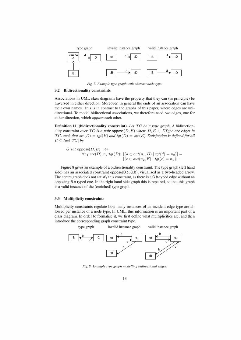
Fig. 7: Example type graph with abstract node type.
3.2 Bidirectionality constraints
Associations in UML class diagrams have the property that they can (in principle) betraversed in either direction. Moreover, in general the ends of an association can havetheir own names. This is in contrast to the graphs of this paper, where edges are uni-directional. To model bidirectional associations, we therefore need two edges, one foreither direction, which oppose each other.
Definition 11 (bidirectionality constraint). Let TG be a type graph. A bidirection-ality constraint over TG is a pair oppose(D,E) where D,E ∈ EType are edges inTG , such that src(D) = tgt(E) and tgt(D) = src(E). Satisfaction is defined for allG ∈ Inst [TG ] by
G sat oppose(D,E) :⇔∀n1:src(D), n2:tgt(D). |{d ∈ out(n1, D) | tgt(d) = n2}| =
|{e ∈ out(n2, E) | tgt(e) = n1}| .
Figure 8 gives an example of a bidirectionality constraint. The type graph (left handside) has an associated constraint oppose(B.c, C.b), visualised as a two-headed arrow.The centre graph does not satisfy this constraint, as there is a C.b-typed edge without anopposing B.c-typed one. In the right hand side graph this is repaired, so that this graphis a valid instance of the (enriched) type graph.
3.3 Multiplicity constraints
Multiplicity constraints regulate how many instances of an incident edge type are al-lowed per instance of a node type. In UML, this information is an important part of aclass diagram. In order to formalise it, we first define what multiplicities are, and thenintroduce the corresponding graph constraint type.
Fig. 8: Example type graph modelling bidirectional edges.
13

Fig. 9: Example type graph with multiplicities
Formally, multiplicities are defined as ordered pairs of natural numbers, where thesecond (higher) number may take the special value ? to indicate unboundedness. Anumber is considered to be within the range of the multiplicity if it is higher than orequal to the lower bound and smaller than or equal to the upper bound.
Definition 12 (multiplicity). A multiplicity is a pair [i, j] ∈ IN× (IN∪{∗}) with i ≤ jor j = ∗. The set of multiplicities is denoted Mult . The special value ∗ indicates thatthe maximum number is not constrained.
To retrieve the lower and upper bounds of multiplicities, we use mappingslow , upp:Mult → (IN ∪ {∗}); i.e., if µ = [i, j] then low(µ) = i and upp(µ) = j.For an arbitrary number n and multiplicity µ ∈ Mult , we write n ∈ µ if low(µ) ≤ nand either upp(µ) = ∗ or n ≤ upp(µ).
In UML, multiplicities can be attached to both the source and the target end of associ-ations; a multiplicity at the source end represents the potential degree of sharing of anode. We will restrict ourselves to target multiplicities, and refer to them simply as themultiplicity of an edge.
Definition 13 (multiplicity constraint). Let TG be a type graph. A multiplicity con-straint over TG is a pair mult(E,µ) with E ∈ EType and µ ∈ Mult . Satisfaction isdefined for all G ∈ Inst [TG ] by
G sat mult(E,µ) :⇔ ∀n:src(E). |out(n, E)| ∈ µ .
Figure 9 gives an example of a multiplicity constraint. The type graph (left handside) has an associated constraint mult(C.b, [2, 5]), visualised by writing the pair [2, 5],without the brackets, near the head of the arrow. The centre graph does not satisfy thisconstraint, as there is a C-typed node (call it n) with only a single outgoing C.b-typededge (i.e., out(n, C.b) = 1 /∈ [2, 5]). In the right hand side graph this is repaired, sothat this graph is a valid instance of the (enriched) type graph.
3.4 Indexing constraints
To capture the notion of an ordered collection from class diagrams, we need to formalisewhat it means for a set of graph nodes to be ordered. To capture this correctly is actuallyquite involved, even though it is conceptually straightforward. Here we make use of theedge indices that are part of the instance graphs (see Definition 7): if an edge type isdeclared as indexed, the edge indices have to be picked from a consecutive range from 1upwards; and moreover (in fact, more importantly), morphisms are required to respectthe edge indices.
14

Fig. 10: Example type graph with an indexing constraint
Definition 14 (indexing constraint). Let TG be a type graph. An indexing constraintover TG is a predicate indexed(E), with E ∈ EType. Satisfaction is defined for allG ∈ Inst [TG ] and all morphisms f between instance graphs G, H ∈ Inst [TG ] by
G sat indexed(E) :⇔ ∀n:src(E),∀e ∈ out(n, E). 1 ≤ ix (e) ≤ |out(n, E)|f sat indexed(E) :⇔ ∀e : E ⇒ ix (fEdge(e)) = ix (e) .
In the context of (type graphs with) indexing constraints, we will always implicitlyrestrict the (iso)morphisms under consideration to those satisfying the constraints.
Figure 10 gives an example of an indexing constraint. The type graph (left handside) has an associated constraint indexed(C.b), visualised by the annotation {indexed}near the arrow head. The centre graph does not satisfy this constraint, as it has two out-going C.b-typed edges with indices {54, 129}, which do not form a consecutive range.This is repaired in the right hand side graph. More importantly, where ordinarily theright hand side graph would be considered symmetric (having two interchangeable B-typed nodes), this is no longer true in the presence of the indexing constraint: the sym-metry (formally, an isomorphism from the graph to itself) maps (n, C.b, 1) to (n, C.b, 2)(where n is the C-typed node in the graph) and hence does not satisfy the constraint,since it does not preserve edge indices.
It follows that, in instance graphs, the edge indices for indexed edge types have tobe included in the diagram, in order for the visual representation to be unambiguous.
3.5 Uniqueness constraints
In general, there may be more than one edge of the same type between the same nodes(as long as they are distinguished by their indices). In many cases, however, this isactually undesirable: one would like to ensure that target nodes occur at most once —in other words, they are unique in the context of the source node and edge type.
Definition 15 (uniqueness constraint). Let TG be a type graph. A uniqueness con-straint over TG is a predicate unique(E), where E ∈ EType is an edge type. Satisfac-tion is defined for all G ∈ Inst [TG ] by:
G sat unique(E) :⇔∀n:src(E).∀e1, e2 ∈ out(n, E). tgt(e1) = tgt(e2) ⇒ e1 = e2 .
Figure 11 shows an example of a uniqueness constraint. The type graph (left handside) has an associated constraint unique(C.b), visualised by the annotation {unique}
15

Fig. 11: Example type graph showing a uniqueness constraint.
near the arrow head. The centre graph does not satisfy this constraint since there aretwo distinct C.b-labelled edges from the right hand side node to the left hand side node.This is repaired in the right hand side graph.
3.6 Acyclicity constraints
Another notion from UML class diagrams that has proved to be quite useful in practiceis that of aggregation or containment. Whereas ordinary edges may impose an arbitrarystructure on the nodes they connect, containment is intended to reflect a hierarchy ofthings. Therefore, when edges in a type graph are declared to be acyclic, the intentionis that the edges in the corresponding instance graphs do not form a cycle.
This type of constraint is in fact quite powerful if the edge types in the hierarchy doform a cycle in the type graph. In that case, there could in principle be instance graphswith arbitrarily large cycles, all of which are ruled out by a single acyclicity constraint.From this it can be seen that the acyclicity constraint is a non-local property, and henceoutside the class of first-order logic.
Definition 16 (acyclicity constraint). Let TG be a type graph. An acyclicity constraintover TG is a tuple acyclic(E1, . . . , En) where E1, . . . , En ∈ EType is a collection ofedge types. Satisfaction is defined for all G ∈ Inst [TG ] by
G sat acyclic(E1, . . . , En) :⇔ {e:Ei | 1 ≤ i ≤ n} is cycle free.
It should be noted that the edge types E1, . . . , En should be read as a set, in which theordering is irrelevant; hence, there are many ways to write down the same constraint.
Figure 12 shows an example of an acyclicity constraint. The type graph (left handside) has an associated constraint acyclic(C.b, B.c) visualised by diamond-shaped dec-orations at the sources of the edge types. (This visualisation always specifies a singleacyclicity constraint, consisting of all diamond-decorated edge types. The case where
Fig. 12: Example type graph showing an acyclicity constraint.
16
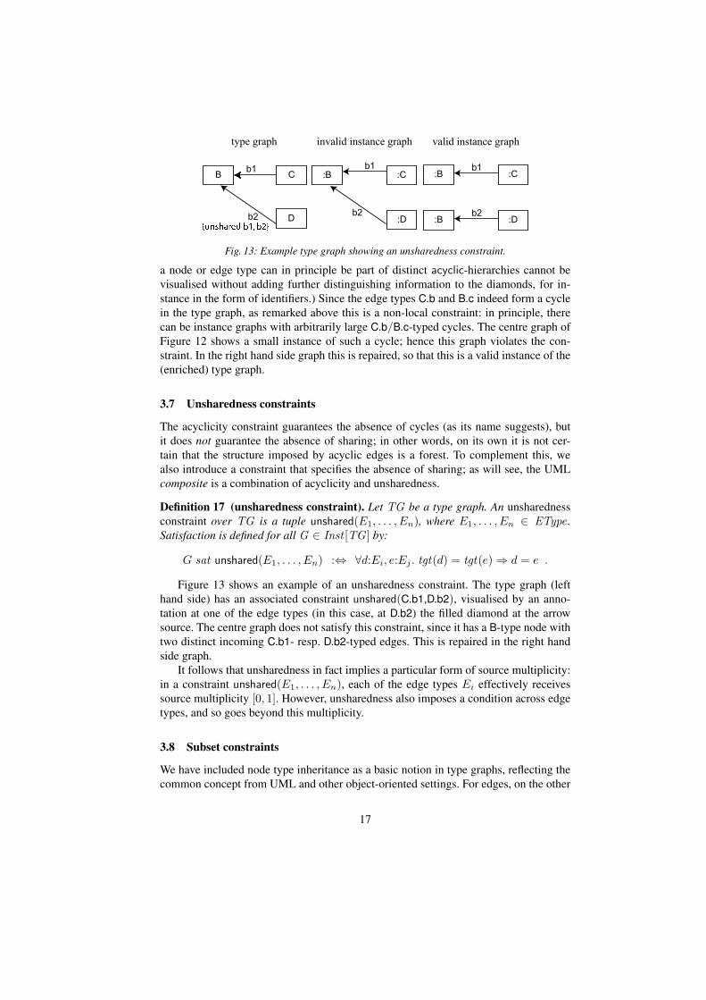
Fig. 13: Example type graph showing an unsharedness constraint.
a node or edge type can in principle be part of distinct acyclic-hierarchies cannot bevisualised without adding further distinguishing information to the diamonds, for in-stance in the form of identifiers.) Since the edge types C.b and B.c indeed form a cyclein the type graph, as remarked above this is a non-local constraint: in principle, therecan be instance graphs with arbitrarily large C.b/B.c-typed cycles. The centre graph ofFigure 12 shows a small instance of such a cycle; hence this graph violates the con-straint. In the right hand side graph this is repaired, so that this is a valid instance of the(enriched) type graph.
3.7 Unsharedness constraints
The acyclicity constraint guarantees the absence of cycles (as its name suggests), butit does not guarantee the absence of sharing; in other words, on its own it is not cer-tain that the structure imposed by acyclic edges is a forest. To complement this, wealso introduce a constraint that specifies the absence of sharing; as will see, the UMLcomposite is a combination of acyclicity and unsharedness.
Definition 17 (unsharedness constraint). Let TG be a type graph. An unsharednessconstraint over TG is a tuple unshared(E1, . . . , En), where E1, . . . , En ∈ EType.Satisfaction is defined for all G ∈ Inst [TG ] by:
G sat unshared(E1, . . . , En) :⇔ ∀d:Ei, e:Ej . tgt(d) = tgt(e) ⇒ d = e .
Figure 13 shows an example of an unsharedness constraint. The type graph (lefthand side) has an associated constraint unshared(C.b1,D.b2), visualised by an anno-tation at one of the edge types (in this case, at D.b2) the filled diamond at the arrowsource. The centre graph does not satisfy this constraint, since it has a B-type node withtwo distinct incoming C.b1- resp. D.b2-typed edges. This is repaired in the right handside graph.
It follows that unsharedness in fact implies a particular form of source multiplicity:in a constraint unshared(E1, . . . , En), each of the edge types Ei effectively receivessource multiplicity [0, 1]. However, unsharedness also imposes a condition across edgetypes, and so goes beyond this multiplicity.
3.8 Subset constraints
We have included node type inheritance as a basic notion in type graphs, reflecting thecommon concept from UML and other object-oriented settings. For edges, on the other
17

Fig. 14: Example type graph with a subset constraint
hand, although there is likewise a notion of specialisation, but no single commonly ac-cepted way to capture this. Instead, UML knows several ways to define specialisation-like relationships between edges, which we here formalise through edge type con-straints.
The first of these is subsetting. An edge type can be declared as a subset of anotherif both its source type and its target type specialise those of the other; its meaning isthen that an edge of the supertype should exist whenever an edge of the subtype exists.
Definition 18 (subset constraint). Let TG be a type graph. A subset constraint overTG is a pair subset(D,E), where D,E ∈ EType are edges in TG , such thatsrc(D) inh src(E) and tgt(D) inh tgt(E). Satisfaction is defined for all G ∈Inst [TG ] by
G sat subset(t, u) :⇔ ∀d:D. ∃e:E. src(e) = src(d) ∧ tgt(e) = tgt(d) .
Figure 14 shows an example of a subset constraint. The type graph (left hand side)has an associated constraint subset(F.b, A.d), visualised by annotating the arrow headof F.b (the “subtype”) with {subsets d}. (Note that d here is just the name, and notthe entire identifier, of the edge type A.d; the namespace A can either be derived fromthe context — in particular the fact that it must be a supertype of F — or, if it is am-biguous, it should be included in the visualisation.) The centre graph does not satisfythe constraint, since it has a F.b-type edge between two nodes without a correspondingA.d-type edge. In the right hand side graph this is repaired, so that this graph is a validinstance of the (enriched) type graph. Note that the stand-alone d-named edge is actu-ally of type A.d, and needs no corresponding F.b-edge; in other words, the implicationin Definition 18 works in one direction only.
3.9 Redefinition constraints
Another specialisation-type relation between edges is that of redefinition. This is inits intention quite similar to subset, but (loosely formulated) instead of implying thepresence of an edge of the “supertype”, redefinition forbids the presence of such anedge. More precisely, if an edge type D redefines another type E, then a node of D’ssource type may no longer have an outgoing E-type edge — instead, this should be aD-type edge.
Definition 19 (redefinition constraint). Let TG be a type graph. A redefinition con-straint over TG is a pair redefine(D,E), where D,E ∈ EType are edges in TG ,
18

Fig. 15: Example type graph with a redefinition constraint
such that src(D) inh src(E) and tgt(D) inh tgt(E). Satisfaction is defined for allG ∈ Inst [TG ] by:
G sat redefine(D,E) :⇔ @e:E. src(e):src(D) .
Figure 15 shows an example of a redefinition constraint. The type graph (left handside) has an associated constraint redefine(F.b, A.d), visualised just like the subset con-straint (see above) but with the keyword redefines rather than subset. The centre graphdoes not satisfy the constraint, since there is an A.d-type edge going out of an F-typenode. In the right hand side this is repaired, by changing the offending edge into anF.b-type; as a result, this instance graph satisfies the redefinition constraint.
3.10 Union constraints
Both subset and redefinition constraints impose consequences on the existence on a“subtype” edge — in one case, the existence and in the other case, the absence of a“supertype” edge. To complement this capability, the union works in the other direction:in this case, the existence of a “supertype” edge implies the existence of a “subtype”edge.
Definition 20 (union constraint). Let TG be a type graph. A union constraint overTG is a tuple union(D,E1, . . . , En), where D,E1, . . . , En ∈ EType are edges in TG ,such that src(Ei) inh src(D) and tgt(Ei) inh tgt(D) for all 1 ≤ i ≤ n. Satisfactionis defined for all G ∈ Inst [TG ] by:
G sat union(D,E1, . . . , En) :⇔∀1 ≤ i ≤ n : subset(Ei, D) ∧∀d:D. ∃1 ≤ i ≤ n, e : Ei. src(e) = src(d) ∧ tgt(e′) = tgt(e) .
Figure 16 shows an example of a union constraint. The type graph (left hand side)has an associated constraint union(A.d, F.b, F.c), visualised by an annotation at the “su-pertype”, that is, at the edge type A.d. The centre graph does not satisfy this constraintsince there is an F.b-edge without a corresponding “supertype” edge, but also an A.d-edge without a corresponding “subtype” edge. This is repaired in the right hand sidegraph by adding both of those edges; as a result, this instance graph satisfies the redefi-nition constraint.
19
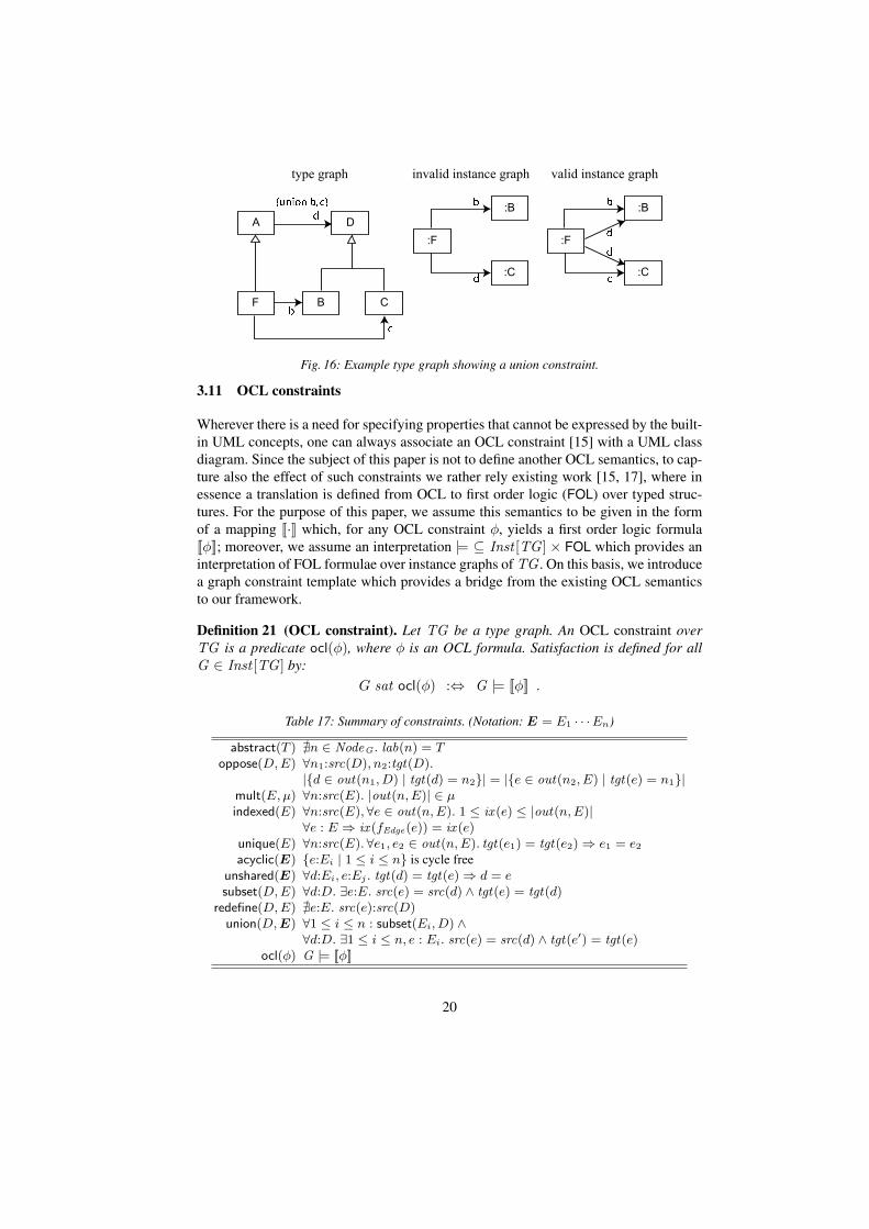
Fig. 16: Example type graph showing a union constraint.
3.11 OCL constraints
Wherever there is a need for specifying properties that cannot be expressed by the built-in UML concepts, one can always associate an OCL constraint [15] with a UML classdiagram. Since the subject of this paper is not to define another OCL semantics, to cap-ture also the effect of such constraints we rather rely existing work [15, 17], where inessence a translation is defined from OCL to first order logic (FOL) over typed struc-tures. For the purpose of this paper, we assume this semantics to be given in the formof a mapping [[·]] which, for any OCL constraint φ, yields a first order logic formula[[φ]]; moreover, we assume an interpretation |= ⊆ Inst [TG ] × FOL which provides aninterpretation of FOL formulae over instance graphs of TG . On this basis, we introducea graph constraint template which provides a bridge from the existing OCL semanticsto our framework.
Definition 21 (OCL constraint). Let TG be a type graph. An OCL constraint overTG is a predicate ocl(φ), where φ is an OCL formula. Satisfaction is defined for allG ∈ Inst [TG ] by:
G sat ocl(φ) :⇔ G |= [[φ]] .
Table 17: Summary of constraints. (Notation: E = E1 · · ·En)
abstract(T ) @n ∈ NodeG . lab(n) = Toppose(D, E) ∀n1:src(D), n2:tgt(D).
|{d ∈ out(n1, D) | tgt(d) = n2}| = |{e ∈ out(n2, E) | tgt(e) = n1}|mult(E, µ) ∀n:src(E). |out(n, E)| ∈ µindexed(E) ∀n:src(E),∀e ∈ out(n, E). 1 ≤ ix (e) ≤ |out(n, E)|
∀e : E ⇒ ix (fEdge(e)) = ix (e)unique(E) ∀n:src(E).∀e1, e2 ∈ out(n, E). tgt(e1) = tgt(e2) ⇒ e1 = e2
acyclic(E) {e:Ei | 1 ≤ i ≤ n} is cycle freeunshared(E) ∀d:Ei, e:Ej . tgt(d) = tgt(e) ⇒ d = esubset(D, E) ∀d:D. ∃e:E. src(e) = src(d) ∧ tgt(e) = tgt(d)
redefine(D, E) @e:E. src(e):src(D)union(D, E) ∀1 ≤ i ≤ n : subset(Ei, D) ∧
∀d:D. ∃1 ≤ i ≤ n, e : Ei. src(e) = src(d) ∧ tgt(e′) = tgt(e)ocl(φ) G |= [[φ]]
20

4 UML Semantics
So far, we have set up a general framework of definitions regarding two special formsof graphs: type graphs and labeled graphs. This is then extended to the notion of model,which is a combination of a type graph and a constraint set. Furthermore, we havedefined a number of types of constraints, and we have defined what it means for alabeled graph to be an instance of a model. In this section we will apply this generalframework to UML class and object diagrams, thus providing a formal, graph-basedsemantics for these diagrams.
4.1 Class Diagrams
The formal meaning of a UML class diagram is that it is a model. An overview of themapping of UML class diagram concepts to the concepts in our framework can be foundin Table 18. The model’s type graph can be easily recognized: each class in the diagramis a node and each directed association is an edge. Non-directed associations translateto pairs of edges with a bi-directionality constraint, where the edge labels correspondto the names of the association ends. Note that our semantics does not provide thepossibility to add a name to the association, i.e. to the pair of edges.
Taking into account the abbreviated notation for attributes as presented in Figure 2,an attribute is an edge to a node from the data signature. In the case of UML the datasignature consists of the four primitive types (String, Real, Int and Boolean). UML isnot very strict in demanding that the type of each attribute should be a primitive type.Therefore, an attribute whose type is non-primitive (i.e. another class) is an edge to anode that is not part of the data signature. In other words, its meaning is exactly thesame as a directed association.
4.2 Constraint Types
Most of the constraint types in our graph-based framework can also be easily recognizedin a class diagram, for instance a multiplicity or bidirectionality constraint is shown ina class diagram in the same manner as we have shown in Figures 8 and 9. However, inclass diagrams a number of constraint types are often used in combination. The UMLnotation is such that there are separate symbols for certain combinations of constrainttypes.
First, we have defined indexing and unique separately, whereas in UML there arefour forms of notation for each combination of these constraints.
1. The default situation in a UML class diagram is that the unique constraint holdsfor every association, whereas the indexing constraint does not, i.e. an associationend represents a set. Whenever no adornment is attached to the association end, thedefault applies.
2. The notation for the situation where both unique and indexing hold, is to adornthe association with ordered, which according to the UML specification [14] shows“that the end represents an ordered set.”
21

Table 18: Mapping of UML class diagram concepts to graphs
Category UML class diagram Graph modelGeneral class type node
primitive type attribute type edge E with tgt(E) ∈ Sortnon-primitive type attribute type edge E with tgt(E) /∈ Sort
Association directed association type edgenon-directed/bi-directional pair of type edges with opposemultiplicity mult-constraintset (default for mult > 1) unique but not indexedbag neither indexed nor uniquesequence indexed but not uniqueordered set both indexed and uniqueaggregation acycliccomposition both acyclic and unsharedOCL constraint ocl
Specialisation inheritance inh-relation on type nodessubset subset constraintredefines redefine constraintunion union constraintUML object diagram Labelled graph
General object nodeobject type node labellink edgelink type edge labelinstance name symbolic id
3. The UML notation bag as adornment to an association means that neither theunique nor the indexing constraint type hold.
4. Finally, when an association end is adorned with sequence, this means that theunique constraint does not hold, but the indexing constraint does.
The second combination of constraints that is commonly denoted by one symbol ina UML class diagram, is acyclic with unshared. The case were both hold, is knownin UML as a composition or composite aggregation, which is denoted using a blackdiamond at the source end of the association edge. When acyclic holds, but unsharednot, the case is known in UML as an aggregation, which is denoted by a white diamondat the source end of the association edge.
4.3 OCL Constraints over Class Diagrams
UML class diagrams can be accompanied by OCL constraints. In our semantics, as wehave seen, these are also translated to graph constraints, of the type ocl(φ), by relyingon the existing OCL semantics (which essentially provides a translation to first orderlogic). In other words, a class diagram together with its OCL constraints is translatedto a model, in the sense of Definition 9. This illustrates the fact that OCL constraintscannot be seen as separate from the class diagram. The base of every OCL expressionlies in the type system defined by a class diagram.
22

4.4 Object Diagrams
Finally we need to address object diagrams. It will be no surprise that we define anobject diagram to be a labeled graph. When a labeled graph satisfies a certain model,for instance a class diagram or a class diagram combined with constraints, it is a validinstance of that model. An overview of the mapping of UML object diagram conceptsto the concepts in our framework can be found in Table 18.
4.5 Evaluation
The semantics presented here should, as any semantics, uphold the commonly knowncharacteristics of UML diagrams, even those that have (unfortunately) not been madeexplicit in the UML specification. A few such characteristics are listed below. This(incomplete) list should provide some confidence in the correctness of our semanticswith respect to the common intuition. Let 〈TG , C〉 be the model representing the classdiagram under consideration.
– The common sense that the {bag}, {sequence}, and {ordered} annotations shouldalways be used in combination with a multiplicity larger than one, can be obtainedfrom our semantics in the following way. Suppose we have mult(E,µ) ∈ C withupp(µ) ≤ 1 for some edge type E, meaning that any instance graph G satisfies
∀n : src(E), |out(n, E)| ≤ 1 .
It immediately follows that also G sat unique(E), so adding unique(E) to C doesnot change the model. This can also be formulated as an implication:
mult(E,µ) ∧ upp(µ) ≤ 1 ⇒ unique(E) .
Furthermore, without loss of generality (since all choices lead to isomorphicgraphs) we can assume ix (e) = 1 for all e ∈ out(n, E). This in turn impliesthat
∀n : src(E),∀e ∈ out(n, E). 1 ≤ ix (e) ≤ |out(n, E)| ≤ 1 .
and hence G sat indexed(E); so, the same implication holds with respect toindexed(E).
– A commonly known characteristic of UML class diagrams is that if the one end ofa bi-directional association is marked {bag} then the other end should be marked{bag} or {sequence}. Likewise, if one end is an (ordered) set, the other end mustbe a set as well.In our semantics, this situation arises when the bi-directionality constraint is com-bined with the uniqueness constraint. This UML characteristics then translates tothe following “law” of graph constraints:
oppose(D,E) ⇒ (unique(D) ⇔ unique(E))
23

– According to the UML specification, the acyclicity constraint should always becombined with bi-directionality: “Only binary associations can be aggregations”([14], page 37). At the same time, only one end of this association can be marked asaggregate. This is in accordance with common sense, which says that a part cannotcontain its container. In our framework this forbidden situation would occur whenthe acyclicity constraint is defined for both edges of a bi-directional association,i.e.:
oppose(D,E) ∧ acyclic(D) ∧ acyclic(E) .
In our semantics, there are no instances that would satisfy such a model; in otherwords, this combination of constraints is inconsistent (i.e., a contradiction).
– Again according to the UML specification “a multiplicity on an aggregate end ofa composite aggregation must not have an upper bound greater than 1” [14], page119). In terms of graph constraints, this means that the following must hold:
oppose(D,E) ∧ acyclic(E) ∧ unshared(E) ⇒ mult(D,µ)with upp(µ) ≤ 1.
In our semantics, unshared(E) implies that for any n:tgt(E) there can be at mostone incoming edge e1:E such that n = tgt(e1). Because of the bi-directionalityconstraint there can then also be at most one edge e2:D with src(e2) = n, namelythe one paired with e1. Thus, the informal characteristic is confirmed by our formal,graph-based semantics.
These cases give confidence that the presented semantics really conforms to theintuition behind UML. On the other hand, our semantics does not support all UMLaspects; in particular, the following are not included:
– Names of associations. Only the role names associated with the association endsare taken into account, because we consider these to be more important.
– N-ary associations, i.e. associations between more than two classes. These tend tooccur very rarely in class diagrams; moreover, the UML specification itself treatsthem more like classes than like associations.
– Derived attributes or association ends. As the name suggests, these are derivedvalues and need not be explicitly part of the formal representation.
– Navigability of associations. We feel that the directionality of the edges in the as-sociation pair provides enough information.
– Operations. These cannot be expressed by a static structure.
5 Conclusions
In this paper we present an elegant and simple semantics of UML class and object dia-grams based on graph structures that are as close as possible to familiar notions in graphtheory. The main insight used is that a UML class diagram cannot be treated as a simpletype graph. It is a much richer structure, which is embodied in our framework by the useof (graph) constraints. The use of constraints also makes it possible to change the givensemantics to include or exclude certain semantic elements. For instance, by disallowingthe abstract class constraint type one can easily define class diagrams without abstract
24

classes. Furthermore, our definitions do not only provide a semantics for both diagramtypes, but for the relationship between them as well.
As stated in the introduction, simplicity was one of our main guidelines. The onlyaddition we made to the familiar notion of labelled graph is the edge indexing function,in order to capture ordered associations. We investigated (and rejected) several alterna-tives. The use of special “collection node types” makes the definition of instance graphmuch more complex. Another possibility is to use hypergraphs, but that in itself makesthe model much more complex. A third option is to use special edges between the targetnodes of an ordered association to represent the ordering, as we have done before in [9].The problem with this solution is that the ordering needs to be local not only to all edgesof the given type, but also to the source node. For instance, in Figure 10 one could adda “next”-edge between the two B-typed nodes, but when another C-typed node wouldin the same manner be connected to the two B-typed nodes there would be no way todistinguish between the two “next”-edges.
In the introduction we stated that the quality of models is determined by precision,consistency, and completeness. Our semantics provide a precise meaning to class andobject diagrams. Furthermore, the consistency of a model, i.e. the existence of instances,can be checked using the given definitions. For instance, we can prove that a model witha bi-directional association that is an aggregate in both directions is inconsistent. Re-search into this “logic of UML models” has so far been scarce (see e.g. [13]). Thecompleteness of a model cannot be guaranteed by our semantics. However, the seman-tics themselves are more complete than any other graph-based semantics that we havefound in the literature. For instance, [1, 11, 3] only visualise a type graph with inheri-tance as a UML class diagram, thus implying a graph-based meaning for class diagramswithout actually defining an UML semantics. [19] includes attributes, associations, andinheritance, but not containment, multiplicity, abstract classes, or edge specialisation.
As a next step, we intend to investigate the integration of our framework with the ex-isting theory of graph transformation. An important issue is to reconciliate our encodingof indexed edges with the requirements of algebraic graph transformations.
A final point we would like to make goes back to the introduction, and concernsthe (scientific) merit of the type of effort we have undertaken in this paper. We believeto have achieved a simple, intuitive and workable graph-based semantics. The fact thatUML was conceived over a decade ago and still no graph-based semantics with thisdegree of completeness had been presented (in contrast to other theoretical bases, e.g.,[12, 7, 16, 10, 5, 2, 8]), indicates that our undertaking was not trivial. Moreover, thereis a great need for such semantics, if ever model-driven engineering is to become adependable method. We know that many of the ideas brought together in this work havebeen presented earlier; however, the strength of this contribution lies in the particularcombination of these ideas. All in all, we believe that the result should be judged notonly on novelty, but on completeness, adaptability, and usability as well. If there is nowell-defined forum where this type of effort can receive recognition, there will be noincentive, and the gap between theory and practice may remain with us forever.
25
References
[1] R. Bardohl, H. Ehrig, J. de Lara, and G. Taentzer. Integrating meta-modelling aspects withgraph transformation for efficient visual language definition and model manipulation. InM. Wermelinger and T. Margaria, editors, FASE, volume 2984 of LNCS, pages 214–228.Springer, 2004.
[2] W. Damm, B. Josko, A. Pnueli, and A. Votintseva. Understanding uml: A formal semanticsof concurrency and communication in real-time uml. In F. S. de Boer, M. M. Bonsangue,S. Graf, and W. P. de Roever, editors, FMCO, volume 2852 of LNDS, pages 71–98. Springer,2002.
[3] J. de Lara, R. Bardohl, H. Ehrig, K. Ehrig, U. Prange, and G. Taentzer. Attributed graphtransformation with node type inheritance. Theoretical Computer Science, 376(3):139–163,May 2007.
[4] H. Ehrig, U. Prange, and G. Taentzer. Fundamental theory for typed attributed graph trans-formation. In H. Ehrig, G. Engels, F. Parisi-Presicce, and G. Rozenberg, editors, ICGT,volume 3256 of LNCS, pages 161–177. Springer, 2004.
[5] A. Evans and S. Kent. Core meta-modelling semantics of uml: The puml approach. InFrance and Rumpe [6], pages 140–155.
[6] R. B. France and B. Rumpe, editors. UML’99: The Unified Modeling Language - Beyondthe Standard, volume 1723 of LNCS. Springer, 1999.
[7] R. Geisler. Precise UML semantics through formal metamodeling. In L. Andrade, A. Mor-eira, A. Deshpande, and S. Kent, editors, Proceedings of the OOPSLA’98 Workshop onFormalizing UML. Why? How?, 1998.
[8] Y. Hammal. A formal semantics of uml statecharts by means of timed petri nets. In F. Wang,editor, FORTE, volume 3731 of LNCS, pages 38–52. Springer, 2005.
[9] H. Kastenberg, A. G. Kleppe, and A. Rensink. Defining object-oriented execution semanticsusing graph transformations. In R. Gorrieri and H. Wehrheim, editors, FMOODS, volume4037 of LNCS, pages 186–201, London, June 2006. Springer Verlag.
[10] A. Knapp. A formal semantics for uml interactions. In France and Rumpe [6], pages 116–130.
[11] S. Kuske, M. Gogolla, R. Kollmann, and H.-J. Kreowski. An integrated semantics for UMLclass, object and state diagrams based on graph transformation. In M. J. Butler, L. Petre,and K. Sere, editors, Integrated Formal Methods (IFM), volume 2335 of Lecture Notes inComputer Science, pages 11–28. Springer, 2002.
[12] K. Lano and J. Bicarregui. Semantics and transformations for uml models. In J. Bezivinand P.-A. Muller, editors, UML, volume 1618 of LNCS, pages 107–119. Springer, 1998.
[13] A. Maraee and M. Balaban. Efficient reasoning about finite satisfiability of uml class dia-grams with constrained generalization sets. In D. H. Akehurst, R. Vogel, and R. F. Paige,editors, ECMDA-FA, volume 4530 of LNCS, pages 17–31. Springer, 2007.
[14] OMG. Unified modeling language: Superstructure. Technical Report formal/05-07-04,OMG, 2005.
[15] OMG. Object constraint language specification, version 2.0. Technical Report formal/06-05-01, OMG, 2006.
[16] G. Overgaard. A formal approach to collaborations in the unified modeling language. InFrance and Rumpe [6], pages 99–115.
[17] M. Richters and M. Gogolla. Ocl: Syntax, semantics, and tools. In T. Clark and J. Warmer,editors, Object Modeling with the OCL, volume 2263 of LNCS, pages 42–68. Springer,2002.
[18] G. Taentzer and A. Rensink. Ensuring structural constraints in graph-based models withtype inheritance. In M. Cerioli, editor, FASE, volume 3442 of LNCS, pages 64–79. Springer,April 2005.
26

[19] G. Varro, K. Friedl, and D. Varro. Implementing a graph transformation engine in relationaldatabases. Journal of Software and Systems Modelling, 5(3):313–341, Sept. 2006.
27