a general model for vhf aeronautical multipath propagation ... working groups...
TRANSCRIPT

AMCP/WG-D/ /WP6
AERONAUTICAL MOBILE COMMUNICATIONS PANEL (AMCP)
Working Group DHonolulu, HAWAII19-28 January 1999
A GENERAL MODEL FOR VHF AERONAUTICALMULTIPATH PROPAGATION CHANNEL
Presented by Arnaud DEDRYVERE
Prepared by Benoît ROTURIER1, Beatrice CHATEAU
Agenda Item:2
SUMMARY
In this paper a general model dedicated to large scale and small scale fading on the aeronautical VHFmultipath channel is introduced. This model is based on previous theoretical and experimental multipathstudies developed in the context of VHF Digital Link (VDL) system validation by MITRE, FAA, DLRand DGAC. This model may be used as a reference model for different scenarios including ground-ground, air-ground and air-air links.
It is shown that a particularity of the aeronautical VHF multipath channel is that in many situations, thelarge scale fluctuation of the mean power is due to the deterministic combination of direct and groundreflected rays. On the contrary, small scale fluctuations are governed by the same mechanisms as inclassical systems, hence it is proposed to use similar modeling techniques.
The proposed model shows a good agreement with measurements in several scenarios.
1 CNS Research Laboratory, Ecole Nationale de l'Aviation Civile, 7 avenue Edouard Belin, BP 4005,31055 TOULOUSE Cedex 4 FRANCE

2
I. Introduction
Propagation channel modeling is an essential task to assess the performance of any digital mobilecommunication system. It is well known that fundamental limitations of communication systems are dueto the propagation channel effect on the signal. In general, these limitations may be due to eithertropospheric propagation, ionospheric propagation or multipath.
In Aeronautical VHF band, ionospheric effects may usually be neglected. Although communications linkscan be established in the low VHF band using sporadic ionospheric reflection or ionised trails left bymeteorites, the signal levels involved are quite weak when compared to nominal aeronautical VHF levels[AGA88]. Problems due to tropospheric propagation exist, in particular ducting problems, and arediscussed in [CHA98].
Multipath signal distortion is the main source of disturbances for VHF Digital Link (VDL) system sinceground and aircraft antennas are non-directional. The ground as well as almost all scattering bodies in thevicinity of an antenna are illuminated, generating multipath.
For any digital mobile communication multipath channel modeling, it is important to have a soundunderstanding of the large scale mean signal power variations as well as the small scale amplitude/phasefluctuations of the signal around the mean value. Both average signal power and fluctuations knowledgeis necessary to compute the bit error rate (BER) of the digital link which is often the most appropriateparameter to assess the effect of the propagation channel on the digital link.
With these objectives in mind, several theoretical and/or experimental studies have been devoted to VDLmultipath propagation channel modeling recently.
Some of these studies have dealt with large scale variations of the signal using either:• a stochastic model (MITRE [DAR96], FAA [DYE97]),• a deterministic model (DGAC [ROT97], [CAL97], [CHA98]). These theoretical models have been compared to experimental results. Some of these studies have focused on small scale variations of the signal using again:• a stochastic model (MITRE [DAR96], FAA [DYE97], DLR [HOE98], DGAC [CHA98]),• a deterministic model (DGAC [ROT97]). These theoretical model, except DLR's, have also been compared to experimental results. Another interesting classification is the domain of application of these studies. The VDL multipathchannel is non-unique and usually different scenarios involving ground - ground with or without line ofsight (LOS), air - ground and air - air links with different mobile speed must be taken into account in ageneral model: • Ground - ground scenario without LOS between transmitter and receiver antenna has been dealt in
DGAC [ROT97], [CHA98] and DLR [HOE98] reports,• ground - ground scenario with LOS between transmitter and receiver antenna has been dealt in
MITRE [DAR96], DGAC [ROT97], [CHA98], DLR [HOE98] reports,• air - ground scenario has been dealt in FAA [DYE97], DGAC [CAL97], [CHA98], DLR [HOE98]
reports,• air - air scenario has been dealt in DLR [HOE98] report.

3
Although an extensive description of all the possible practical situations has not yet been done, the abovelisting of previous studies shows that an appreciable amount of work involving theoretical analysis aswell as experiments has been done so that a deep understanding of the VDL multipath channel existtoday. However, since some models have been applied to a restricted set of scenario, and since thetheoretical studies use different (deterministic or stochastic) models both for large and small scalevariations, the description of this channel may seem a little bit confuse.
The aim of this paper is to present a synthesis of the above mentioned studies to obtain a general modelfor VDL multipath propagation channel. This numerical general model is shown to be simple,computationally efficient and general enough to handle the different scenarios. This model could be usedto refine the existing VDL budget links neglecting multipath (e.g. [RTC97]) but could also be used in anumerical simulator (e.g. SPW) including VDL transmitter and receivers models in order to have arealistic description of the whole VDL physical layer as shown in Figure 1. Although in some peculiarsituations this model may not be adequate, most of the time and for most scenarios it should provide amultipath signal distortion close to reality.
Figure 1. Digital Communication System / Physical Layer
The main feature of this model is to combine a deterministic method as proposed in DGAC [ROT97],[CAL97], [CHA98] reports to model large scale variations and a stochastic method as proposed inMITRE [DAR96], FAA [DYE97], DLR [HOE98], DGAC [CHA98] reports to model small scalevariations of the multipath propagation channel.
This description is original when compared to classical ground - ground or satellite - air/groundcommunication systems where the whole large scale and small scale multipath model is usuallystochastic, but theoretical analysis and experimental results show that the combination of VHF band, non-directional antennas, antennas at important height above the ground and finally airport configurationmake this deterministic description of the large scale variations the most adequate for a general model. Onthe other side, since the physical phenomena governing small scale variations are the same for VDLpropagation channel than for classical ground - ground or satellite - air/ground propagation channel, theproposed stochastic models for small scale variations are in close correspondence to those used inclassical communication systems.

4
II. Multipath Propagation Channel Model
II.A. General considerationsA huge amount of work has been done in the past in the context of mobile ground - groundcommunications as well as in satellite - ground/air mobile communications and many papers andtextbooks address these subjects (e.g. [BEL73], [PRO95]). It is often considered that a complete blockdiagram description of the multipath propagation channel including the different effects which have to becharacterized looks like the one shown in Figure 2 [SKL97].
Figure 2. Multipath propagation channel characterization
Before going further into details of the description of large and small scale fading blocks for VDL, wehave to introduce a set of fundamental functions representing the multipath propagation channel, as theywill be the reference for the following considerations in this paper.
First of all, we introduce e(t) which is the time varying VDL signal supplied by the RF transmitter to thetransmitting antenna and s(t) which is the time varying VDL signal affected by the propagation channel atthe receiver antenna terminal (cf. Figure 1). Since usually power is a relevant quantity, it is interesting togive to real valued functions e(t) and s(t) physical dimensions of (watts)1/2 so that the average suppliedpower to the transmitter antenna as well as the average available power at the receiving antenna terminalare proportional to some time averaging of e(t)2 and s(t)2 .
Clearly, the proposed multipath propagation channel will involve transmitter and receiver antennascharacteristics as well as electromagnetic scattering yielding multipath. The advantage of this descriptionincluding antennas is to be able to work with scalar e(t) and s(t) functions rather than intricate timevarying vector fields which have to be used if antennas are excluded of the propagation channel model. Insome situations it could also be interesting to include transmitter and/or receiver filters. It has not beendone here, but it would be very easy to modify the proposed model to do so.

5
Now, if we further suppose that there is a common time reference to all mobiles and that the channel islinear, it is possible to introduce a general convolution relationship between e(t) and s(t):
s t e t h t d( ) ( ) ( , )= −−∞
∞
∫ τ τ τ (1)
In Equation 1 h(τ,t) is the time varying impulse response of the propagation channel and e(t-τ) is thetransmitted signal at time t-τ. Equation 1 shows that the channel is completely characterized when thefunction h(τ,t) is known.When the multipath propagation channel may be described with a time varying sum of attenuated αk anddelayed τk replicas of the transmitting signal, h(τ,t) may be written as:
( ) ( )( )h t t tk kk
N t
( , )( )
τ α δ τ τ= −=
∑1
(2)
Where δ(.) is the Dirac distribution. Equation 2 is valid when the signal is delayed on each path withoutbeing distorted. This is usually the case when the spectral width of the signal is not too important and isvalid for VHF aeronautical channel.
As stated above, the multipath propagation channel characterization is usually divided between largescale and small scale fading, hence it is interesting to make this distinction clear and rewrite Equation 2:
( ) ( )( ) ( ) ( )( )h t t t
h t
t t
h t
LSk
LSk
k
N LS t
Large Scale
SSk
SSk
k
NSS t
Small Scale
( , )
( , ) ( , )
( ) ( )
τ α δ τ τ
τ
α δ τ τ
τ
= − + −= =
∑ ∑1 11 24444 34444 1 24444 34444
(3)
In Equation 3, the time varying impulse responses governing large scale (LS) and small scale (SS) fadingare introduced. For this distinction to have a physical meaning, the number of paths in the large scale partmust be low (usually 1 or 2), while the number of paths in the small scale part must be high. Asmentioned before, the parameters of these impulse responses are usually determined using deterministicor stochastic methods.
The propagation channel characteristics may equivalently be defined in the frequency domain. The timevarying transfer function of the channel H(f,t) is simply the Fourier Transform in τ of h(τ,t), that is:
( ) ( ) ( ) ( )H f t t e j k t f
H f t
t e j k t f
H f t
LSk
LS
k
N LS t
Large Scale
SSk
SS
k
NSS t
Small Scale
( , )
( , ) ( , )
( ) ( )
= − + −= =
∑ ∑α πτ α πτ2 2
1 11 244444 344444 1 244444 344444(4)
Equations 3 and 4 show that the multipath propagation channel acts as a linear time varying filter on thesignal. It may also be convenient, especially in numerical simulations, to work with the equivalentcomplex baseband signals of e(t) and s(t). In this case, one may prefer to use the equivalent low passtransposed filter which may be easily derived from (3) and (4) [PRO95].

6
II.B. Large Scale Fading
II.B.1 DiscussionLarge scale fading is due to motion over large areas, involving distances much larger than wavelength. Itis often convenient to describe independently the mean value of the large scale fading (block 2) and thelarge scale variations around this mean value (block 3), although block 2 alone is sufficient in some cases.There is a large number of practical situations where such a description is adequate [PAR92] and someimportant cases are summarized below:
1.For a satellite - ground system with directional antennas, it may be considered that only one direct pathis involved and the mean signal power variation may be described with the usual inverse squaredistance law with negligible large scale variations around the mean.
2.For a high frequency (no ground wave) ground - ground system involving non-directional antennas inline of sight over an approximately smooth dielectric earth, it may be shown that a direct + reflectedpath combination yield a 4th power inverse distance law with negligible large scale variations aroundthe mean.
3.For an air - ground system involving omnidirectionnal antennas in line of sight over an approximatelysmooth dielectric earth in the vicinity of the ground antenna, it may be shown that direct + reflectedpath combination yield a large scale oscillation with distance around the free space mean power.
4.For ground - ground mobile systems involving shadowing and large scale ground roughness, the directand/or ground reflected path often do not exist. Usually the mean signal power variation is describedstochastically with a nth power inverse distance law and large scale variations around the mean areconveniently described with a log-normal stochastic law.
Models 1, 2 and 3 of the large scale variations are deterministic, that is they are totally determined oncethe parameters of the scene are fixed. This deterministic description using one (case 1) or two (case 2,3)rays is very interesting in practice when it is valid since no experimentation is necessary and thecomputational burden is negligible. On the contrary, model 4 is entirely stochastic and its parameters haveto be determined from experimentation, which may be difficult and expensive to set up.
In the context of VHF Digital Link (VDL) data link, these large scale description have been used inprevious attempts of multipath propagation channel characterization:
• Model 1 is used in RTCA [RTC97] to assess budget link margin, although it is recognized in the samedocument to be not realistic enough.
• Model 2 has been shown [ROT97], [CHA98] to be in close correspondence with a large database ofmeasured VHF mean power for ground-ground communications at Toulouse-Blagnac Airport(France).
• Model 3 has been shown [CAL97], [CHA98] to be in close correspondence of measured VHF meanpower for air -ground communications around Toulouse-Blagnac Airport (France).
• Model 4 has been used in [DAR96] to fit ground - ground measurements at Hanscom Civil Airport(USA) and in[DYE97] to fit measured air - ground VHF mean power at Duluth and Aspen Airports(USA).
Model 1 has to be considered for VHF aeronautical channel as a mean value only (block 2 of Fig.2) verysimple model, giving no information to characterize the large scale variations (block 3 of Fig.2). Althoughmodel 4 may be of interest in some specific situations as discussed later, theoretical analysis andexperimental results show that the deterministic models 2 or 3, both based on the combination of direct +
7
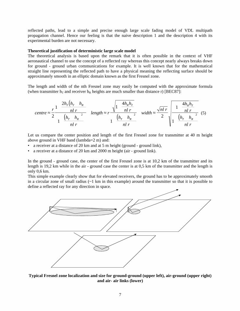
reflected paths, lead to a simple and precise enough large scale fading model of VDL multipathpropagation channel. Hence our feeling is that the naive description 1 and the description 4 with itsexperimental burden are not necessary. Theoretical justification of deterministic large scale model The theoretical analysis is based upon the remark that it is often possible in the context of VHFaeronautical channel to use the concept of a reflected ray whereas this concept nearly always breaks downfor ground - ground urban communications for example. It is well known that for the mathematicalstraight line representing the reflected path to have a physical meaning the reflecting surface should beapproximately smooth in an elliptic domain known as the first Fresnel zone. The length and width of the nth Fresnel zone may easily be computed with the approximate formula(when transmitter hT and receiver hR heights are much smaller than distance r) [BEC87]:
( )
( ) ( ) ( )centre
rh h h
n r
h h
n r
length r
h h
n r
h h
n r
widthn r
h h
n r
h h
n r
T T R
T R
R T
T R
R T
T R
≈+
+
++
≈+
++
≈+
++2
12
1
14
12
14
1
2 2 2λ
λ
λ
λ
λ λ
λ
(5)
Let us compare the center position and length of the first Fresnel zone for transmitter at 40 m heightabove ground in VHF band (lambda=2 m) and:• a receiver at a distance of 20 km and at 5 m height (ground - ground link),• a receiver at a distance of 20 km and 2000 m height (air - ground link).
In the ground - ground case, the center of the first Fresnel zone is at 10,2 km of the transmitter and itslength is 19,2 km while in the air - ground case the center is at 0,5 km of the transmitter and the length isonly 0,6 km.This simple example clearly show that for elevated receivers, the ground has to be approximately smoothin a circular zone of small radius (~1 km in this example) around the transmitter so that it is possible todefine a reflected ray for any direction in space.
Typical Fresnel zone localization and size for ground-ground (upper left), air-ground (upper right)and air- air links (lower)

8
On the contrary, for low height receivers such as in ground - ground communications, virtually the wholeground distance between transmitter and receiver has to be approximately smooth for the concept of areflected ray to have a physical meaning. This condition will often exist in a propagation media such as anairport where by nature most of the area is devoted to approximately smooth surfaces such as runways,taxiways, parking, but certainly not in an urban propagation media where large buildings of differentheights and shapes may exist on most of the link between transmitter and receiver.
Finally for air - air links if transmitter and receiver heights are 2000 m high and separated by 20 km, thelength of the first Fresnel zone located at the mid-point is also roughly 1 km, hence the ground surfacealso needs to be approximately smooth only on a restricted part of the path between the ground projectionof the transmitter and receiver.
The term "approximately smooth" introduced in the above examples means here smooth in the sense ofRayleigh criterion. Electromagnetic analysis and experiments on rough surfaces show that ([BEC87]chap. 14) if
4 1πα
λ∆hsin
<<(6)
where ∆h is the standard deviation of Gaussiandistributed irregularities above the mean groundplane, α the grazing angle and λ the wavelength,the concept of a specular reflected ray still holdswith a reduction of reflection coefficientmagnitude. It may also be shown that thisreduction may be computed with the relation:
R R with e
h
Approx Smooth Smooth.
sin
= =−
ρ ρπ
αλ
1
24
2∆
(7)
The smooth reflection coefficient is reduced sincethe surface roughness also creates an incoherentdiffuse electromagnetic field whose energy istaken from the coherent reflected field, as shownqualitatively in Figure 3(b). It may be shown[BEC87] that this incoherent diffuse field createssmall scale fading. Due to inverse wavelengthdependency, equations 6 and 7 show that a roughsurface will seem less rough to lower wavelength.Hence, the use of VHF band rather than UHF orL band is also a factor which makes moreimportant the ground reflection.Figure 3 (a) Smooth surface,
(b) Approximately Smooth surface,(c) Rough surface

9
II.B.2 Large scale fading proposed model
Line of sight (LOS) scenariosIn accordance with the previous discussion, for the air - ground, air - air and ground - ground with line ofsight scenarios we finally propose to write the time varying transfer function of large scale fading as thedeterministic sum of a direct and a reflected path:
( ) ( ) ( ) ( )H f t t e j t f t e j t f
LS DD
RR( , ) = − + −α πτ α πτ2 2
(8)
Where D (resp. R) index stands for Direct (resp. Reflected). The four parameters αD, τD, αR, τR may beexplicitly computed once the geometry is fixed, leading to a deterministic description of HLS.
Figure 4. Geometrical and ground parameters for large scale model
If we adopt the conventions of figure 4 and if both transmitter and receiver antennas are polarizationmatched, we have the simple expression for the large scale transfer function:
H f t g g f fe jkr
rR f f
e jkr
rLS T R T
DirRDir
D
DVert Smooth T
RefRRef
R
R
( , ) max max .=−
+−
λπ
ρ4
(9)
Where gTmax, gRmax are the maximum field gains of transmit and receive antennas, and fT, fR are complexvalued functions inferior to 1 in module describing amplitude/phase variation of the field radiationdiagram of these antennas. RVert.Smooth is the smooth earth reflection coefficient in vertical polarizationdepending upon grazing angle, and dielectric (ε,σ) parameters of the ground. Rvert as well as a set ofrepresentative dielectric parameters valid in VHF band are discussed in [CHA98]. ρ is the reductionfactor due to ground roughness given in equation 7.

10
The time dependency is not explicit in equation (9) but it has to be noted that once the (xT(t), yT(t), zT(t),xR(t), yR(t), zR(t)) coordinates of the phase center of possibly mobile transmit and receive antennas areknown, all the parameters intervening in equation (9) are easy to calculate and fixed.
From (8) and (9) it is easy to obtain the large scale time varying impulse response:
( ) ( )( ) ( ) ( )( )h t t t t tLS D D R R( , )τ α δ τ τ α δ τ τ= − + − (9bis)
From (8) and (9), one may also derive the complex baseband large time varying impulse response whichwill be used later (f0 is the central frequency of a VDL channel):
( ) ( ) ( )( ) ( ) ( ) ( )( )~( , )h t t e j f t t t e j f t t
LS DD
D RR
Rτ α π τ δ τ τ α π τ δ τ τ= − − + − −2 20 0 (9ter)
In (9bis) and (9ter) αD, τD, αR, τR are derived from (9) with:
αλπ
τ
αλπ
ρ τ
DD
T R T
DirRDir
DD
RR
T R TRef
RRef
Vert Smooth RD Vert Smooth
rg g f f
r
c
rg g f f R
r
cArg
R
kc
= =
= = −
4
4
max max
max max ..( )
In practice the main difficulty lies in determining the radiation properties (i.e. gTmax, gRmax, fT, fR ) oftransmit/receive antennas but the experiments/theoretical formula comparison presented in [ROT97],[CAL97], [CHA98] show that it is a good approximation for a general model to use the axisymetricradiation diagram functions fT, fR of a vertical half-wavelength dipole:
( )fT R,
cos( cos( ))
sin( )θ
πθ
θ= 2
And maximum gain gmax of transmitter and receiver such as defined in [RTC97], that is:
20 4 20 21510 10log ( ) log ( ) .max maxg dBi g dBiaircraft ground= − =
Without line of sight scenarioIn the case of less frequent, but still to be considered for a complete model, of ground - ground withoutline of sight communication, a deterministic attempt has been done in [ROT97] to compute large scalefading with Uniform Theory of Diffraction (UTD), and the experiment/theoretical model comparisonshowed errors between 5 and 15 dB. This error was attributed to the necessary simplifications of theshape and constitutive parameters of the several shadowing buildings introduced in the UTD software,and it was concluded that a stochastic approach would give an order of error of the same magnitudewithout the need of lengthy simulations.The nth power law with log-normal variations should give adequate results in this case, but there is a needof further experimental investigations on representative airport shadowing situations to obtain confidencein the parameters of these laws.

11
II.B.3. Large Scale Fading Examples
Ground-ground and air -ground scenarios large scale fading deterministic models have been experimentedat Toulouse Blagnac Airport (France). A larger number of theoretical/experimental results based on thesimultaneous measurement at 1 Hz of VHF power and precise (~1m, 95%) position using ToulouseBlagnac experimental DGPS have been presented in [ROT97], [CAL97], [CHA98] both for vertical andhorizontal polarization. These results show that, in accordance with the above discussion, except in thecase of air-ground links with a very low receiver height, the deterministic large scale model yields closecorrespondence with measurements.
Ground-ground scenario
In this experiment, the receiving vehicle was running around the airport runways as shown on the 2Dairport plan (Fig. 5) starting from the point of x,y coordinates (0,0) (DGPS station), following the upperpart of the path up to x = 1000 mm (5Km) and coming back along the lower part of the path. Thetransmitter was at the remote transmitter station shown with a (+) sign on fig. 5.
Figure 5. Toulouse Blagnac Airport plan view (up)Ground-ground measurements in the line-of-sight of the transmitter (down)
In this experiment most of the transmitter/receiver parameters where known:• the frequency was f0=118MHz, the transmitter power was PT = 15 W, the transmitter antenna was at
40 m above the airport ground, the receiver antenna was at 3.2 m above the ground,• the transmitter antenna vertical electric dipole (with reflector) maximum gain was assessed at gTmax =
3dB from the manufacturer gain curves, the mismatch loss was 0.1 dB, the cable loss was 1.3dB andthe splitter loss was 2dB, hence the global transmitter losses were LT= -3.4 dB,

12
• the receiver vertical electric half wavelength dipole antenna maximum gain was the theoretical gRmax =2.14dB, the mismatch loss was 0.5 dB, the cable loss was 1.5dB, hence the global receiver losses wereLR= -2 dB.
Once the transmitter and receiver losses are known, the received power may be calculated with the budgetlink formula:
P P L L HR T T R LS=2
Where HLS is given by equation (9). In the following figures, by measurement point is meant the index ofthe receiver position, or equally the index of the power data acquisition, during each experiment. In Fig. 6 we can see that the large-scale variation of the received power decreases as the vehicle getsfarther from the transmitter and increases as the vehicle gets closer. It may also be observed that themeasured power fluctuates around the large scale mean value as a noise-like process which correspondsto small-scale variations. As discussed above, the free-space attenuation does not agree well with themeasured power whereas the direct + reflected two-ray model on smooth wet ground (εr = 12, σ = 0.4S/m,∆h = 0), which corresponded to experimental conditions, gives a much better prediction of the large-scalefading.
0 500 1000 1500 2000-75
-70
-65
-60
-55
-50
-45
-40
-35
-30
-25
measurement point
power dBm
Figure 6. Power measurements and predictions for receiver on ground in the line-of-sight of the
transmitter
measurements
free-space large-scale model
direct+reflected large-scale model

13
Air-ground scenario In this experiment, a Beechcraft 90 was flying along the runway axis from 20NM north to 20NM south atdifferent flight levels (1Nm = 1852m). The transmitter was still at the remote transmitter station and thefrequency was 118MHz. The receiver antenna gain, the SWR, the splitter and cable loss were set to unitysince their values as well as the airborne antenna maximum gain were unknown. A global loss parameterwas experimentally determined by using the measured results in Fig. 7. For FL200 (Flight Level 200 = 6000m), Fig. 7 shows that, as anticipated the free-space model is stillinadequate for predicting the large-scale fading. The direct + reflected ray prediction is in very goodagreement with the large-scale measured fading. The nature of the ground was adjusted empirically in themodel so that the nulls of the model and experimental results were at the same location. The groundmodel was found to be smooth (∆h = 0) and dry ((εr = 2, σ = 0.05 S/m) which was in accordance with theexperimental conditions.
-20 -10 0 10 20-90
-85
-80
-75
-70
-65
-60
-55
distance from transmitter South => North Nm
power dBm
Figure 7 Power measurements and predictions for in flight receiver at FL200
measurements
free-space large-scale model
direct+reflected large-scale model
The same experiment was carried out at FL100 (2000m) and good agreement was also found betweenmeasured and predicted large-scale fluctuations. Finally, since the limits of the model are expected to be determined by the accuracy of the groundreflection prediction, an experiment at lower FL was also performed. Fig. 8 shows the powermeasurements and predictions for a receiver altitude of 1500ft (460m). Direct + reflected predictions areless precise than at FL 200 but still in rather good agreement with measured results. Also, a greaterazimuthal asymmetry between the left side and the right side of the measured curve than with the FL200experiment may be observed.

14
This greater discrepancy, as discussed above, may probably be due to the greater extension of the firstFresnel zone as FL decreases. This larger Fresnel zone may include asymmetric south/north terrainfeatures. In effect, the length of the first Fresnel zone computed from equation (5) is found to be only323m for a receiver at FL200, 1.7km for a receiver at FL100 but 13.5km for a receiver at an altitude of1500ft.
-20 -10 0 10 20-90
-85
-80
-75
-70
-65
-60
-55
-50
-45
-40
distance from transmitter South => North Nm
power dBm
Figure 7. Power measurements and predictions for in flight receiver at FL 1500ft
measurements
free-space large-scale model
direct+reflected large-scale model

15
II.C. Small scale fading
II.C.1 Discussion Small scale fading involves variation of the signal on very short distances (typically half of awavelength). This small scale fading results from a large number of scattered rays incident on the receiverantenna, as shown in figure 8.
Figure 8. Small scale fading due to some Toulouse Blagnac airport buildings In a mobile system, the rapid delay/phase variation of each ray with small displacements causes theamplitude and phase of the received signal to vary over short distances. Since a large number of rays isusually involved, although this scattering process is basically deterministic and may be modeled withdeterministic methods such as UTD as shown in e.g. [ROT97], the small scale fading looks like astochastic signal and is best modeled as such. The starting point is equation (10):
( ) ( )( )h t t t
stochastic model
Small ScaleSS
kSS
kk
NSS t
( , )( )
τ α δ τ τ= −=
∑11 24444 34444
(10)
When N is large2 and since the mean value terms (usually direct+reflected paths) have been included inthe large scale part of the impulse response, it is well known that in many practical cases the amplitude ofthe received signal s(t) delivered by the small scale propagation channel has zero mean and is Rayleighdistributed. However it is usually not sufficient to label the small scale propagation channel as a Rayleighfading channel, more information on the statistics has to be given to obtain a precise model.
2 In practice N greater than 6

16
A complete small scale stochastic model is usually based upon the classical wide sense stationaryuncorrelated scattering (WSSUS) hypothesis [BEL73], [PRO95], which has been widely used in thecontext of mobile communication channel characterisation. With the WSSUS hypothesis it may be shown that it is sufficient to specify: • the delay spread of the channel, that is the probability distribution of delays (block 5 of fig. 2),• the time variance of the channel, that is the Doppler distribution on the set of delayed rays or
otherwise equivalently the probability density function of the direction of arrival of rays and themobile speeds (block 6 of fig. 2).
Two extreme cases for the channel delay spread are known as flat fading and frequency selective fading:• in the flat fading case, the maximum value τmax of significant delays is very small as compared to the
symbol duration Ts, hence it may be considered that intersymbol interferences (ISI) are negligible. Inthe frequency domain this condition means that the function H(f,t) has negligible variations with f inthe frequency band occupied by the signal, hence the flat fading denomination,
• on the contrary, when ISI exist, the H(f,t) transfer function has significant variations in the frequencyband of the signal and the multipath propagation channel is said to be frequency selective.
Two extreme cases for the channel time variance also exist and are known as slow fading and fast fading:• in the slow3 fading case, the maximum Doppler frequency is very small when compared to the spectral
width of the signal. In the time domain, it means that the channel characteristics are constant on a timescale of at least the duration of one symbol4,
• on the contrary, in the fast fading case the channel characteristics are changing during the transmissionof a symbol so that it is distorted when it reaches the receiver.
It is not obvious a priori to assess to which class belongs a given signal on a given channel since theabove definitions are purely qualitative and many parameters are involved. In [CHA98], heuristicconsiderations led to classify the small scale ground-ground and air ground channel as flat and slowfading, i.e. negligible ISI exist and the channel is invariant during the transmission of a few consecutivesymbols. In [HOE98/2], simulations reproducing the VDL physical layer showed that for D8PSK, thetime variance of the channel may be considered as slow fading, but that even with low maximum delayspread of 7 µs, the channel has to be considered as frequency selective since an effect on the BER exist.In air-air links, larger maximum delay spread may occur due to ground scattering for elevated aircraft,hence for a general model valid for ground-ground with/without LOS, air-ground, air-air links it is wise toassume that the channel is frequency selective in general.
3 The term slow (resp. fast) fading is sometimes used in some multipath papers (e.g. [PAR92], [DAR96],[ROT97]) to reference large scale (resp. small scale) variations of the signal. To avoid confusion, it isproposed to use these terms with the definitions given in this paper which are also in accordance with[SKL97], [DYE97], [HOE98], [CHA98].4 For differential transmission schemes such as D8PSK, the channel should be invariant on a time scale ofat least two symbols for slow fading.

17
II.C.2. Small Scale Fading Proposed Model
Such a slow fading/frequency selective model has been described in [HOE98]. In this model the low passfilter equivalent to h(τ,t) is first introduced:
( ) ( ) ( )( )~( , )
( )
h t t e j f t tSSSS
k
SSk SS
k
k
NSS t
τ α π τ δ τ τ= − −=
∑ 2 0
1
(11)
where f0 is the center frequency of a VDL channel. It is then be showed that equation (11) may beapproximated with:
( ) ( )~( , )h t
C
Ne
j f tSS
k Dkk
k
N
τθ π
δ τ τ≈+
−=
∑2
1
(12)
Where each path has an individual random null-phase θk, a delay τk, a Doppler frequency fDk and aconstant amplitude C/N1/2. The C/N1/2 normalization term ensures that the average energy of the smallscale fading process is C2. The random numbers fDk (-fDmax<fDk<fDmax ) and τk (0<τk<τmax) have to begenerated in accordance with the probability density functions describing the time variance and the delayspread of the channel while θk (0<θk<2π) only needs to be uniformly distributed.
In this model it is important to note that some parameters have to be defined a priori:1) adequate probability distribution functions for the time variance and delay spread of the channel,2) parameters of these distributions such as τmax and fDmax,3) the value of C, which is the square root of the average power of the small scale fading process.
Several proposition exists in previous studies:1) Probability distribution functions taking into account the different scenarios as realistically as possible
have been proposed in [HOE98] for the time variance and delay spread of the channel. On thecontrary, in [CHA98] the simple Jake model5 [PAR92] is used for the time variance of air-ground andground-ground scenarios. Since the computational burden of more realistic [HOE98] probabilitydensity functions seems to be low ([CHA98] model is a subset of these models) in our opinion theyshould be considered as the reference for future studies.
2) In [RTC97] fDmax is estimated by taking into account the maximum relative speed ofreceiver/transmitter mobile. In the same document τmax is also estimated but with values which seem tobe very large: for air-ground paths τmax = 200 µs and for air-air paths τmax = 1 ms . It has to be notedthat if in some configuration these delays could exist, the difference in path loss (200 µs ↔ 60 km, 1ms ↔ 300 km) would lead to considerable attenuation. One of the aim of the FAA study [DYE97] wasto measure the channel delay spread around airport with different topographical environments(suburban with rolling hills and mountainous). The preliminary results show that for both sites τmax isinferior to 10 µs. In [HOE98], values of τmax have been extrapolated heuristically at 33 µs for air-ground scenario and at 66 µs for air-air scenario, without experimental validation.
3) In [CHA98], C has been estimated from measurements of the small scale fading average power onground - ground and air - ground scenarios.
5 In this model it is assumed that the direction of arrival of the multiple paths are uniformly distributedaround the mobile in the horizontal plane and zero delay spread is assumed.

18
While the point 1) seems to be quite mature by now, it appears that they are a large number of differentevaluations in propositions 2) for the maximum delay spread of the VDL channel. Values extrapolatedfrom ground mobile communication systems such as GSM may be of some help for ground- groundscenario, but are useless for air-ground and air-air scenarios. It is proposed that future theoretical orexperimental studies efforts should be devoted to assess realistic maximum values of τmax. This point isespecially important, because intersymbol interference, when it exists, might be one of the major sourceof the VDL BER degradation.
II.C.3. Small Scale Fading Example
In this experiment, the vehicle was moving in the vicinity of buildings and was no longer in the LOS ofthe transmitter located at the remote transmission center of the airport. Fig. 9 shows the path followed bythe vehicle on a 2D area of Toulouse Blagnac airport as well as the power measurements on this path.
600 700 800 900 1000 110050
100
150
200
250
x-axe mm
y-axe mm
scale 1/5000
0 100 200 300 400-90
-80
-70
-60
-50
measurement point
power dBm
Figure 9. Toulouse Blagnac Airport plan view (up)Ground-ground power measurements with the transmitter screened by buildings (down)
In this case since no direct and ground reflected paths exist, the amplitude distribution of the fluctuationsis Rayleigh distributed. As discussed above, small scale Rayleigh fading shown in figure 9 may bemodeled with equation (12). Figure 10 shows a sequence of small scale fading using Jakes modelapproximation of equation (12):

19
430 435 440 445 450 455 460 465 470 475 480-15
-10
-5
0
5
Normalized time (fm*t) or distance (d/lambda)
Hss
(f0,
t) (
dB)
Rayleigh simulator with Jake's method, 32 oscillators
Figure 10. Small scale fading model example
It may be seen that the autocorrelation characteristic length of the small scale fading function when thereceiver is moving is of the order of half-wavelength. This means that the mean distance between amaximum and a minimum is roughly of this magnitude and is a well known characteristic of small scalefading.
This may lead, in the static parking scenario, to large differences in received field strength for smalldifference in position (1 or 2 m) if no spatial diversity (that is several uncorrelated receiving antennas)exist.
In the dynamic slow fading case, which has been shown to be a reasonable assumption for VDL, it maybe considered that each symbol suffers a gain or a reduction in amplitude (shown in figure 10) as well asa phase rotation (not shown in figure 10). The global effect of these instantaneous gain and phasevariations due to small scale fading is that the BER is degraded. This degradation may be preciselyquantified for a given system (see e.g. [HOE98/2] for VDL D8PSK).

20
II.D. Combination of Large Scale and Small Scale model
II.D.1 Discussion
Finally, it is interesting to combine in a single expression the above proposed models of large scale andsmall scale fluctuations of the signal. This global model could be used in a numerical simulator of theVDL physical layer, in this case the time domain equivalent baseband filter is the most interestingquantity and is obtained in combining (9ter) and (12):
( ) ( ) ( )( ) ( ) ( ) ( )( )
( ) ( )
~( , )h t t e j f t t t e j f t t
Deterministic Large Scale Fading
C
Ne
j f t
Stochastic Small Scale Fading
DD
D RR
R
k Dkk
k
N
τ α π τ δ τ τ α π τ δ τ τ
θ πδ τ τ
= − − + − −
++
−=
∑
2 2
2
0 0
1
1 2444444444444 3444444444444
1 2444444 3444444
(13)
This global model is proposed for scenarios with line of sight (LOS) between transmitter and receiver,hence it may be applied to most practical cases execpt the ground-ground without LOS scenario whereformula (12) alone is sufficient.
Within this global model intersymbol interferences due to large delays of the deterministic groundreflected path, which may occur for example in the air-air scenario, as well as the simultaneous effect ofstochastic small scale fading are taken into account, hence it should give a realistic evaluation of theaeronautical multipath propagation channel on a given digital link scheme.
An important particularity of this global model is that it is a Rice model, but the K6 coefficient of this Ricedistribution varies with time (or equivalently position of mobiles) through the evolution of the meanpower of the deterministic large scale fading. This remark could seem of no interest since this is the casein reality for all Rice distributions, but the unique feature of the VDL multipath channel, that is the highlyprobable combination of a direct and a reflected path, yields fast variations of the large scale mean valuewhile the power of small scale variations remain approximately constant. This is different from classicalground - ground communications systems such as GSM, where for a given scenario, both large scale andsmall scale average power remain approximately constant and where a unique K factor for a givenscenario may be defined.
Due to large scale fading variation, the K factor of the global Rice model may be assessed to vary over a30 dB interval for scenarios shown in figure 6 and 7 (since C is assumed to be constant). Hence, asdiscussed above, it seems unphysical to try to affect a single value of K factor at a given scenario as wasproposed in previous studies ([DAR96], [DYE97], [HOE98]).
The strategy developed in this paper is different and may be summarized as follow:
1. Try to assess (with experimental results or diffraction/rough surface scattering models) the constant C(the average power of small scale fluctuations),
6 K may defined as the ratio of the large and small scale average power.

21
2. Define a scenario with given transmitter/receiver 3D time varying position as well as the otherparameters intervening in equation (9), then compute the mean power of large scale fluctuations,
3. The varying K factor may then be computed at each position of the mobile(s). If desired, likely-to-happen worst cases K factor may be identified by looking at the areas where the large scale power islow. Then, the K factor corresponding to these areas may be then computed and defined as a referenceworst case K factor for the scenario.
II.D.2 Complete Model Example
Two examples are shown using ground - ground and air - ground scenarios introduced in paragraph II.B.3.In figure 11 and 12, a small scale fading similar to the one shown in Fig. 10 is superposed with anexperimentally determined constant power level (C parameter of equation (12)) over the large scale meanvalue. It may be seen that in both cases the global large + small scale fading model developed in thispaper (dark line) is very close to the real world measured signal (gray line), yielding good confidence inthe validity of the models as well as the underlying hypothesis.
Figure 11. Ground-ground Line Of Sight scenario, theoretical/experimental comparison

22
0 10 20 30 40 50 60 70-95
-90
-85
-80
-75
-70
-65
-60
-55
Transmitter Aircraft distance (Nm)
VHF Power (dBm)
Figure 12. FL 200 air-ground scenario, theoretical/experimental comparison
In figure 11 and 12, it is easy to identify the areas of worst case K factor. In figure 11 it will occur aroundmeasurement point 800 while in figure 12 it will occur around Transmitter/Aircraft distance of 47 NM.With this method, as discussed above, realistic worst case situations may be assesses for the definedscenarios.
23
III. Conclusion and recommendations
• In this paper a general model adequate for large and small scale fading on the aeronautical VHFmultipath channel has been introduced. This model may be used for a large number of practicalsituations including ground - ground, air - ground and air - air links.
• It has been shown that a particularity of the aeronautical VHF multipath channel is that in many
situations, the large scale fluctuation of the mean power is due to the deterministic combination ofdirect and ground reflected rays. This combination of rays leads to rapid mean power variation even onrestricted areas (e.g. on an airport), hence large scale modeling techniques derived from classicalground - ground or satellite - ground systems where this phenomenon does not exist do not seem to bereally appropriate.
• On the contrary, small scale fluctuations are governed by the same mechanisms as in classical systems,
hence it is proposed to use similar stochastic modeling techniques. However appropriate parametershave to be agreed on, especially for air - ground and air - air scenarios. This should be the aim offurther studies on this subject.
• This model may be used to refine existing budget links for VDL taking into account realistically large
scale as well as small scale multipath effect on the signal. This model may also be used to check, at thedesign or validation level, different modulations, error coding techniques and transmission protocolson VHF multipath channel.
• The members of the group are invited to take into consideration the aeronautical VHF multipath
propagation model introduced in this paper and, after discussion and amending, possibly adopt it as areference for future studies on VDL multipath.

24
IV. Bibliography
[AGA88] "Propagation effects and circuit performance of modern military radio systems with particularephasis on those employing bandspreading", AGARD conference proceedings N°442, ElectromagneticWave Propagation panel Symposium, Arcueil, France, 17-21 October 1988.[BEC87] P. Beckmann, A. Spizichinno, "The scattering of electromagnetic waves from rough surfaces",Artech House Inc. 1987.[BEL73] P.A.Bello, "Aeronautical channel characterization,'' IEEE Trans. Com., vol COM-21, no 5, pp548-563, May 1973.[CAL97] P. Calmejane, B. Roturier, B. Château, "Data Broadcast Power Budget", EUROCAE, London,16-17 December 1997.[CHA98] B. Château, "VHF Propagation Channel Modeling for Aeronautical Mobile Communications",PhD report (in French), Toulouse, 07 Oct. 98.[DAR96] L. Darian, W. Wilson, "VHF Channel Propagation Measurements", RTCA SC-172/WG2/WP147, 14 - 16 Aug. 1996.[DYE97] G. Dyer, T. Gaudette Gilbert, "Channel Sounding Measurements in the VHF A/G RadioCommunications Channel", AMCP WG/D8, WP/19, Oberpfafenhoffen Germany, Dec. 2-11 1997.[HOE98] P. Hoeher; E. Haas, "Aeronautical Channel Modeling at VHF Band", DLR note, 22/07/98,Oberpfaffenhofen, Germany.[HOE98/2] P. Hoeher; E. Haas, "Comparison of 4DPSK versus 8DPSK for VDL mode 3", DLR note,22/07/98, Oberpfaffenhofen, Germany.[PAR92] J.D; Parsons "The mobile radio propagation channel", Pentech Press Publishers, London, 1992.[PRO95] G.Proakis, Digital Communications. New York: McGraw-Hill, 3rd ed., 1995.[ROT97] B. Roturier, B. Chateau, B. Souny, P. Combes, H. Chevalier 'Experimental and theoretical fieldstrength evaluation on VHF propagation channel for aeronautical mobiles' Aeronautical MobileCommunication Panel WG-D Madrid, Spain, 7th April to the 12th 1997.[RTC97] RTCA DO224, chap. 3, draft 04/97[SKL97] B. Sklar, "Rayleigh Fading Channels in Mobile Digital Communication Systems", IEEECommunications Magazine, Sept. 97, pp 136-155.