a framework for wireless sensor networks management for precision viticulture and agriculture
TRANSCRIPT

This article appeared in a journal published by Elsevier. The attachedcopy is furnished to the author for internal non-commercial researchand education use, including for instruction at the authors institution
and sharing with colleagues.
Other uses, including reproduction and distribution, or selling orlicensing copies, or posting to personal, institutional or third party
websites are prohibited.
In most cases authors are permitted to post their version of thearticle (e.g. in Word or Tex form) to their personal website orinstitutional repository. Authors requiring further information
regarding Elsevier’s archiving and manuscript policies areencouraged to visit:
http://www.elsevier.com/authorsrights

Author's personal copy
A framework for wireless sensor networks management for precision viticulture and agriculture based on IEEE 1451 standard
Miguel A. Fernandes a,e, Samuel G. Matos b,e, Emanuel Peres f,e, Carlos R. Cunha c,a, Juan A. López d,P.J.S.G. Ferreira b, M.J.C.S. Reis b,e, Raul Morais f,e,⇑a CITAB — Centre for the Research and Technology of Agro-Environment and Biological Sciences, Quinta de Prados, 5001-801 Vila Real, Portugal b IEETA — Signal Processing Laboratory, Dept. Electrónica, Telecomunicações e Informática, Universidade de Aveiro, 3810-193 Aveiro, Portugal c IPB — Instituto Politécnico de Bragança, Campus de Santa Apolónia, 5301-854 Bragança, Portugal d DSIE — División de Sistemas e Ingenierı́a Electrónica, Technical University of Cartagena, Campus Muralla del Mar s/n, Cartagena E-30202, Spain e UTAD — Universidade de Trás-os-Montes e Alto Douro, Quinta de Prados, 5001-801 Vila Real, Portugal f INESC TEC (formely INESC Porto) and UTAD, University os Trás-os-Montes e Alto Douro, Vila Real, Portugal
a r t i c l e i n f o
Article history:Received 24 September 2012 Received in revised form 21 March 2013 Accepted 1 April 2013
Keywords:IEEE 1451 Precision agriculture Precision viticulture Wireless sensor networks GatewayIEEE 802.15.4
a b s t r a c t
Precision viticulture (PV) and precision agriculture (PA) requires the acquisition and proce ssing of a vast collection of data coming typically from large scale and heterogeneous sensor networks. Unfortunately,sensor integration is far from being simple due to the number of incompatible netwo rk specifications and platforms. The adoption of a common, standard communication interfa ce would allow the engineer toabstract the relation between the sensor and the network. This would reduce the development efforts and emerge as an important step towards the adoption of ‘‘plug-and-play’’ technology in PA/PV sensor networks. This paper explores this need and introduces a framework for smart data acquisition in PA/ PV that relies on the IEEE 1451 family of standards, which addresses the transducer-to -network interop- erability issues. The framework includes a ZigBee end device (sMPWiNodeZ), as an IEEE 1451 WTIM (Wireless Transducer Interface Module), and an IEEE 1451 NCAP (Network Capable Application Proces- sor) that acts as gateway to an information service provider and WSN (Wireless Sensor Network) coordi- nator. The paper discusses the proposed IEEE 1451 system architecture and its benefits in PA/PV and closes with results/lessons learned from in-field trials towards smarter WSN.
� 2013 Elsevier B.V. All rights reserved.
1. Introductio n
PA and PV practices depend on the acquisition, transmission and processin g of a vast collection of data coming from a large scale, heteroge neous sensor network (Camilli et al., 2007 ). These characterist ics and the obvious need for wireless data transmis sion immediatel y raises two issues. The first is energy-related. The chal- lenge is how to obtain sufficient energy and how to manage it, sothat all electronic devices can enjoy virtually uninterrupt ible oper- ation. Previous work (Morais et al., 2008a,b ) gave valuable infor- mation on how to support devices that communicate with each other in an IEEE 802.15.4/Zig Bee mesh network with energy har- vesting techniques to power data acquisition devices with multiple sensors.
The second issue has to do with the normalization and interop- erability related to the multiplicity of sensors, sensor output types,multi-vendor data acquisition platforms and network support. In
PA/PV practices there are many sensors with different types of out- put: voltage, current, wired digital (RS-485, SDI-12) and many other types. This diversity affects the way sensors are integrated in a data acquisition network.
The multiplicity of incompatible network specifications and dis- tinctive data acquisition platforms make the integration of hetero- geneous sensors far from simple (Tani and Cugnasca, 2005 ). The adoption of a common and standard communicati on interface toabstract the sensor/network /user relation would cut down devel- opment efforts, reduce installation and configuration complexi ty,and facilitate the ‘‘plug-and-play’’ of sensors to a network (Oostdyket al., 2006; Hu et al., 2007; Lee, 2008 ), improving interoperab ility and reducing the implementati on, deploym ent and maintenanc ecosts.
Solutions to meet these challenges would contribute decisively to improve precision viticulture practices. The need for a frame- work for interoperabilit y to accommodate these systems and sup- port heterogeneous sensor applications using consensus -based standards to connect sensor networks has been noted before (Songand Lee, 2007 ). Chen and Helal (2008, 2009) had reviewed and ana- lyzed the standards developed to normalize the process of acquir-
0168-1699/$ - see front matter � 2013 Elsevier B.V. All rights reserved.http://dx.doi.org/10.1016/j.compag.2013.04.001
⇑ Corresponding author at: UTAD — Universidade de Trás-os-Montes e Alto Douro, Quinta de Prados, 5001-801 Vila Real, Portugal.
E-mail address: [email protected] (R. Morais).
Computers and Electronics in Agriculture 95 (2013) 19–30
Contents lists available at SciVerse ScienceDi rect
Computers and Electr onics in Agricu lture
journal homepage: www.elsevier .com/locate /compag

Author's personal copy
ing and handling data from transduc ers (Echonet, SensorML,DeviceKit, Device Description Language, IEEE Transducer ML and IEEE 1451), and concluded that the IEEE1451 family of standards arises as the most comprehensive . Besides ensuring the appropri- ate standardization of data and procedures for data acquisition, italso normalizes the process of communicati ons between devices which, in itself, may represent a huge benefit provided that the implementati on of these standards is adequately structured with the necessary services support.
Our perspective is that the combination in a framework of stan- dards such as IEEE 1451 and IEEE 802.15.4/Zig Bee will effectively simplify the integration of devices and equipment in a distributed PA/PV environment, which is characterized by heteroge neous data acquisition systems. This will free farmers from the technical is- sues often met in such systems (Song and Lee, 2007 ).
In line with this perspective, the present paper describes the architecture and implementation of a comprehens ive framework that transforms data acquisition platforms and makes possible the ‘‘plug-and-play’’ connection of various sensors. In our opinion,the need for and usefulness of such a framework has been felt for long, but its implementation has been left behind mainly due tothe complexity of the IEEE 1451 family of standards.
This article is organized as follows: After introducing the prob- lem of interoperab ility in Section 1, Section 2 presents a brief over- view of IEEE 1451 and what benefits can be extracted from the simplification of configuration and use procedures of wireless sen- sor networks in PA/PV practices. Section 4 presents the hardware and software that have been used and how the MPWiNodeZ plat- form described in Morais et al. (2008a) has been upgraded to be- come fully IEEE 1451 compliant. Regarding the WSN sink node,the functiona l architecture of an in-field gateway, where all ser- vices necessary for the implementation of a complete IEEE 1451 system have been incorporate d, is also described . Section 5 de-scribes the IEEE 1451 impleme ntation and the sequence of opera- tions needed to interact with a data acquisition platform. Inaddition, we present a brief description of the IEEE 1451 manage- ment tool, developed in Java language, which accesses the in-fieldgateway and allows to configuring the devices and collect all data from a proof-of-con cept WSN. It ends with lessons learned from this research and valuable information on how to implement acomplex but comprehensive standard that can be effectively used to create smarter PA/PV technologie s.
2. Overview of IEEE 1451 standard
Important efforts have been concentrated on the definition,functionality and communicati on standards for smart sensors.The goal is interoperab ility for a wide range of applications . The smart sensor, with appropriate local decision-making capability,can act as an intelligent node in a network, with interoperab ility aimed as the key argument for an obvious need to support various data acquisition platforms across different networks for network independen t operation. Such effort would help expedite the devel- opment of networked smart transducers. Towards this goal, the IEEE and the National Institute for Standards and Technology (NIST) have pioneere d the development of a set of standards known as IEEE 1451.
The IEEE 1451, a family of Smart Transduc er Interface Stan- dards, describes a set of open, common, network-indep endent communicati on interfaces for connecting transduc ers (sensors oractuators) to microprocesso rs, instrumenta tion systems, and con- trol/field networks. The key feature of these standards is the defi-nition of Transducer Electroni c Data Sheet (TEDS), fully described in IEEE Std 1451.0-2007, which stores transduc er identification,calibration, correctio n data, measure ment range, manufacture-re-
lated information , and other information , which can be remotely retrieved through a common set of interfaces enabling a ‘‘plug- and-play ’’ procedure for transducer handling. The characteristics of self-configuration and self-descrip tion provided by TEDS help to minimize human errors and by manually entering of data for configuration reduce the need for technical expertise for setting up and maintaining a monitoring system (Oostdyk et al., 2006 ).
A simplified functional structure of a IEEE 1451–based system isdepicted in Fig. 1. IEEE 1451 divides a sensor network system into two general categories of devices, the Network Capable Application Processo r (NCAP) and Transducer Interface Module (TIM). NCAP isa processor -based device that acts as a gateway between two levels of a sensor network with two different interfaces.
To the lower level, the NCAP exchanges data with a set of TIM devices where transducers are attached through Transducer Chan- nels (TC). To this effect, NCAP incorporates a communicati ons sup- port to ensure connectivity with the TIM according to the communi cations technolo gies adopted by the IEEE 1451 family.To the higher level, the NCAP represents the interface of a distrib- uted monitoring system to a higher level of a network where IEEE Std 1451.1-199 9 specifies a simple, complete object model for building smart sensor and actuator-based systems. Remote access to WSN data is thus facilitated by a set of standard services and functiona lities that form a layer of middlew are services for net- work managemen t applications .
Support communi cations between NCAP and TIM is normalized and described separately by a subset of IEEE 1451, regardless of the subset IEEE 1451.0, where several possibilities exist: point-to- point (IEEE 1451.2), approved wireless radios (IEEE 1451.5), and RFID systems (IEEE 1451.7). The subset IEEE 1451.5 introduce sthe Wireless Transducer Interface Module (WTIM), a particular case of TIM where communi cation is based on an approved wire- less radio (IEEE 802.11, IEEE 802.15.4/6LoW PAN, Bluetooth or IEEE 802.15.4 /ZigBee). In any case all the specifications for effective communi cations are containe d in the structure s of Physical TEDS (format, fragmentation and packaging methods for the messages used in communicati ons technology).
Each TIM includes the TEDS associated with each transduc erwhich completely defines it. Furthermore, the NCAP may request the TIM’s TEDS, in order to interpret correctly each sensor reading,or send TEDS to be stored in each TIM by using any approved com-
Fig. 1. Under IEEE 1451, a sensor/actuator system is divided into two parts: aTransducer Interface Module (TIM) containing the sensing or actuating element and including signal-conditioning circuits, and a Transducer Electronic Data Sheet (TEDS), digital data that identifies the type of sensor, its calibration information,scale factor, and more. Each TIM is connected to a network-capable applications processor (NCAP), which provides an interface to any network, by a subset of the IEEE 1451 standard.
20 M.A. Fernandes et al. / Computers and Electronics in Agriculture 95 (2013) 19–30
Author's personal copy
munications medium. More information on all TEDS can be found in IEEE Std 1451.0-2007.
3. IEEE 1451 in PA/PV environments
PA/PV applicati ons often depend on spatial and temporal vari- ability studies and employ variable rate technolo gy (VRT) to man- age crop inputs. Not surprisingly, they show one of the highest rates of adoption of information technology and communications technology in agricultu re.
In these studies and/or techniques, an enormous amount of data is collected in real-time by sensors that measure a wide variety ofparameters related to crop growth. The wide diversity and heteroge- neity of available sensors for this purpose places serious difficultiesboth for end users and manufactur ers. The end users have to struggle with the configuration of the recording equipme nt, and manufac tur- ers need to worry about making their sensors compatib le with the majority of the data collection equipment. The adoption of the IEEE 1451 in PA/PV applications aims to simplify these procedures across all distributed and heterogeneous environments .
Since the publication of the IEEE 1451 family of standards, sev- eral studies have been carried out (Wei et al., 2005; Oostdyk et al.,2006; Nemeth-Johan nes et al., 2007; Song and Lee, 2008; Wobsc- hall et al., 2009; Higuera and Polo, 2010; Seng et al., 2011; Barrero et al., in press ). Higuera et al. (2009) described an IEEE 1451 imple- mentation of a WSN based on IEEE WSN 802.15.4/ZigBee where WTIMs were implemented using Tmote Sky modules (Moteiv Cor- poration, USA). NCAP was implemented over the same Tmote Sky module with a USB connection to a computer. The application interface to the sensor network was developed in LabVIEW and itallows the sending of commands to the WTIM and data storage in a database. This work contributes to the enhancement of IEEE Std 1451.5 ZigBee PHY TEDS by adding eleven new registers for ZigBee support. However, it does not take into account PA/PV spec- ificities and only works on transactions initiated by the NCAP, anoption that makes impossibl e sending out data from the WTIM to the NCAP at periodic intervals without the need for pooling the WTIM.
Tani and Cugnasca (2005) in turns analyzed the application ofIEEE 1451 in PA and how it could help to improve the processes of adoption of WSN and how the various players could benefit from the introduction of standards with interoperabilit y characterist ics,and exchange data independently of the communications network.They point out that the various services provided by the IEEE 1451 network element allow for the implementation of two aspects con- sidered essential: the integration of sensors and data acquisition platforms on the same network communicati ons standard and availability of data in SI units.
Specifically for PA, Wei et al. (2005) describe a weed sensing system based on IEEE 1451 and ISO 11783, a communicati on pro- tocol used in many agricultu ral machines and based on the SAE J1939 protocol (which includes CANbus). The NCAP is connected to other devices using the ISO 11783 bus, which enables connec- tion to non–IEEE 1451–systems. However, only part of the soft- ware module that handles the NCAP interface was based on the IEEE 1451.1. It also described the hardware and software of the implemented TIM (IEEE Std 1451.2-199 7) and its TEDS. It con- cludes that IEEE 1451 provides a flexible solution for the integra- tion of embedded systems from different manufactur ers. The modular design and ‘‘plug-and-p lay’’ capability are attractive and so IEEE 1451 may be a major help to speed up further developmen tof PA technologies.
In the context of IEEE 1451 and its integration into PA/PV envi- ronments, we associate the data acquisition network with WTIM devices and their TC, which correspond to the deployed transduc-
ers (sensors and/or actuators). On the other hands, network coordi- nation is left to a NCAP as a part of an in-field gateway, which manages the WTIM devices and performs basic data integration and aggregat ion. The adoption of the IEEE 1451 viewpoint brings several advantages:
� Uniform device description — every device has a correspondi ngdescription in the TEDS. As a result, it is always possible toobtain informat ion about any transduc er: physical variable,response time and operating modes, among others.� Easier installation and maintenanc e — incorporation of addi-
tional devices is greatly simplified, in a step towards ‘‘plug- and-play ’’ capability. The TEDS incorporate d in the WTIM sup- ply all the required information in a transparent way to the acquisition system. Replacing or upgrading sensors (for exam- ple, to improve accuracy) becomes a simple matter.� Heteroge neity support — IEEE 1451 was conceived with diver-
sity in mind, and in concept it is well suited to the PA/PV sce- nario, in which the monitoring of a variety of physical variables is the rule.� Data integrati on and aggregation — the values of the physical
variables acquired in the field (temperature, solar irradiance,relative humidity, etc.) can be transmitted in SI units. This dis- tributes the overall required processing and greatly simplifiesthe processin g, integration and aggregation of data.� Diagnost ic — The state registers associated with the TIM and
their TC allow detecting and report any malfuncti ons to subse- quently carry out any correctio n.
To the best of our knowled ge, there is no implementation of this standard in the universe of PA/PV as comprehens ive as the one re- ported in the next sections. For example, we are not aware of any other work in which a WTIM can start a data transacti on over anIEEE 802.15.4/Zig Bee network by its own initiative, i.e., without the need for polling by the NCAP.
4. Material s and methods
The scenario chosen to incorporate the set of IEEE 1451 stan- dards in a PA/PV environment, and serve as a testbed for develop- ing and testing intelligent data acquisition devices, comprises a set of data acquisition units with all hardware resources needed toimpleme nt all IEEE 1451 services over a WSN based on the IEEE 802.15.4 /ZigBee, and an in-field sink node responsible to manage all the data gathering process. Since each analog sensor is not com- pliant with IEEE 1451, the sMPWiN odeZ data acquisition platform was upgraded to become an IEEE 1451.5 WTIM, where the at- tached sensors have their TEDS/TC stored in the WTIM memory.In the following sections, the functional architecture of the net- work used in this research and the most relevant aspects of the impleme ntation are described.
4.1. Architecture overview
The solution that we propose to address several frequently occurring problems in WSN for PA/PV applicati ons relies on the sMPWiN odeZ platform and iPAGAT gateway (Peres et al., 2011 ).A number of sMPWiN odeZ nodes are deployed throughout the area of interest, to monitor and acquire data from a number of possible heteroge neous data sources. The incorporation of IEEE 1451 ser- vices in the sensor network yields a new view of it in terms ofNCAP and WTIM entities. On one hand, the iPAGAT gateway be- comes (or incorporate s) the IEEE 1451 NCAP, allowing external data access using IEEE 1451 services through the iPAGAT data inte- gration system. On the other hand, the data acquisition platforms
M.A. Fernandes et al. / Computers and Electronics in Agriculture 95 (2013) 19–30 21

Author's personal copy
become WTIM entities that operate under IEEE 802.15.4/Zig Bee.Fig. 2 illustrates the functional architecture of a WSN operating un- der IEEE 802.15.4/ZigBee and IEEE 1451.5, from the point of view ofthe application considered in this work: monitoring a large num- ber of heterogeneous data sources in PA/PV.
A set of WTIM is deployed in the field, operating under a net- work configuration determined by IEEE 802.15.4/Zig Bee. The infor- mation about the associated sensors is described in TEDS,eliminating the need to configure the remote system for the correct interpretation of the stored data. The iPAGAT thus becomes one ofthe central components of this distributed data acquisition system.Firstly, it coordinates all the WTIM to which it is connected over IEEE 802.15.4 /ZigBee, allowing data collection by category. Sec- ondly, it offers an internal set of services that allow data storage in a local database, which can be accessed subsequent ly by means of external queries. Finally, the network becomes fully scalable since an arbitrary number of iPAGATs is allowed. This brings toour distribut ed architecture a normalization of the configuration and insertion procedures of the platforms and sensors in the net- work, greatly simplifying tasks such as sensor upgrading, and therefore cutting down system and maintenanc e efforts.
4.2. Functional description of the in-field gateway and network nodes
The software structure of the iPAGAT gateway was deeply chan- ged to accommod ate all necessary IEEE 1451 NCAP services to cre- ate a smart, distributed monitoring network. Fig. 3 overviews the inclusion of IEEE 1451 family of standards over an existent IEEE 802.15.4/Zig Bee WSN accordin gly to Fig. 2.
As can be seen in this architectur e, the NCAP is seen essentially as a gateway between the external network and the remaining ele- ments of the IEEE 1451 system, the WTIM (Wiczer and Lee, 2005 ).From the point of view of the external network, the WSN manager uses the NCAP IEEE 1451.1 API to access and manage WSN data tofill the iPAGAT local database. To accomplish these goals, the iPA- GAT implements the following NCAP services:
� IEEE 802.15.4/ZigBee physical interface — Hardware device that supports IEEE 802.15.4/ZigBee and, being part of iPAGAT, oper- ates as a ZigBee coordinator for creating and managing the
WSN. It must also implement the services to add and remove devices from the ZigBee network, manage the communication paths, ensure data exchange, among other;� IEEE 1451.5 services — Software layer that impleme nts IEEE
1451.5 subset responsible for all processing and exchange ofmessages between NCAP and WTIM when communicati ons are performed on IEEE 802.15.4 /ZigBee;� IEEE 1451.0 services — Software layer that deals with all IEEE
1451.0 services. The NCAP must be able to interpret all informa- tion received from each WTIM and sending commands and TEDS for the WTIM and associate d TC. It is also required that the NCAP can identify all sensors attached to each WTIM, inter- pret essential information about sensing units, measurement limits, acquisition times, modes of operation, and other related informat ion;� IEEE 1451.1 services — This layer is an example of an external
network interface, allowing remote access to information con- tained in the NCAP. There are other alternatives including the HTTP protocol described in IEEE 1451.0 subset and a set ofSmart Transducer Web Services proposed by Song and Lee (2007).
In the architecture represented in Fig. 2, three managemen t lev- els are shown. At the WSN level, a set of sMPWiNode Z devices incorporate the necessary IEEE 1451 services to become a WTIM on IEEE 802.15.4/ZigBee communi cation technology. Despite being a mesh-typ e network, i.e., some devices operate as routers, the connectio n between each WTIM and its NCAP is a logical star which illustrate s the abstraction layer that covers all IEEE 802.15.4 /ZigBee network devices. Each sMPWiN odeZ unit can operate as a ZigBee router in which case, as it is only required totransmit network packets, does not require IEEE 1451 services since there is no need to interpret the data. The iPAGAT represents the second level, the entity responsible for in-field collecting and processin g data before making them available to the managemen tlevel, which can coordinate and centraliz e data from one or more iPAGATs in a distributed architecture.
As can be inferred from the observati on of Fig. 3, iPAGAT gate- way had seen its software structure grow with the inclusion of IEEE 1451 services that builds the NCAP. Its core is now built around a
Fig. 2. Illustration of an IEEE 1451 WSN compliant network deployed over a vineyard, emphasizing IEEE 1451 concepts and entities. Each WSN node is a WTIM device while the NCAP acts as a sink node (gateway) to collected data.
22 M.A. Fernandes et al. / Computers and Electronics in Agriculture 95 (2013) 19–30

Author's personal copy
data aggregat ion engine, a real-time alert system (RTAS) and aWSN manager that makes MySQL data inserts into a local database.Access to iPAGAT, and consequently to the NCAP, is accomplished through its data integration system that grant access to data stored in local database and enables remote gateway configuration.
4.3. The sMPWiNodeZ platform and WTIM services
The sMPWiN odeZ platform, illustrated in Fig. 4, is an upgrade version of the MPWiNodeZ (Morais et al., 2008a ) and implements all functions to turn it into a WTIM IEEE 802.15.4/Zig Bee.
It has a 32-bit RISC microcontro ller with IEEE 802.15.4 /ZigBee support (JN5148, Jennic, UK) with 128 KB RAM, 128 KB ROM and 4 MB flash memory. In order to meet the energy needs for perpet- ual operation (when operating as a router) the sMPWiNode Z plat- form can use three independen t power sources: solar, wind and moving water in irrigation pipes, as described in Morais et al.(2008b), allowing its internal LiPo battery to charge even when the system is in sleep mode. These energy transducers were also specified as IEEE 1451 transducers, where their TC were character- ized within the WTIM structure. The protection against excessive discharge of the battery is also carried out by hardware. The sys- tem power is provided by a high efficiency DC-DC converter
(MAX1673, Maxim Integrate d Products, USA) and a second con- verter is used exclusively for sensors power supply, being activated only when needed for readings. Analog inputs are provided allow- ing the connection of sensors with voltage output, an input for sen- sors with frequency output and a digital input for sensors with embedde d digital protocol (SPI, I2C). A separate EEPROM (25LC020A, Microchip, USA) has been included for storing all WTIM TEDS. A real-time clock (DS1343, Maxim Integrated Prod- ucts, USA) provides all timing signals needed for scheduling tasks and time stamps associated with sensor readings.
The sMPWiNode Z platform is ruled by a set of software struc- tures responsib le for energy, communicati ons and peripherals managemen t, with special emphasis on reducing energy consump- tion. Fig. 5 illustrate s the structure of software services with emphasis on IEEE 1451 and its relations with the main application.The interface block called Sensors and actuators HW interface isresponsib le for physical interaction with the transducers, such astheir powering, signal conditionin g and analog-to-d igital conversio n.
Fig. 4. Picture of the sMPWiNodeZ platform, an IEEE 1451 WTIM.Fig. 5. sMPWiNodeZ platform software structure, which ensures its operation inaccordance with IEEE 1451.0 and IEEE 1451.5 IEEE 802.15.4/ZigBee.
Fig. 3. Functional architecture of the iPAGAT gateway acting as a IEEE 1451 NCAP and related WTIM data acquisition platforms, based on sMPWiNodeZ. iPAGAT core uses IEEE 1451 NCAP services to access WSN data and store it into a local MySQL database using a WSN manager.
M.A. Fernandes et al. / Computers and Electronics in Agriculture 95 (2013) 19–30 23
Author's personal copy
The sMPWiNode Z platform implements all IEEE 1451.0 services (defines TEDS structure, command and response messages formats and state registers) and IEEE 1451.5 services (responsible for data exchange between a WTIM and NCAP on IEEE 802.15.4/ZigBee net- works). Two types of messages are defined: set and setRsp.Thefirst one is used to send all kinds of data between devices, i.e.,TEDS, sensor readings, the register readings, and others, while setRsp messages are used to confirm delivery of data packets and to identify potential errors during the communication process.During data reception several operations are performed (unpack-ing, error checking and messages defragmentation) before it can be handled by the IEEE 1451.0 layer. When a WTIM sends a mes- sage, this layer is responsible for the generation of the appropriate response, i.e., receive data from the lower layer (IEEE 1451.0) and execute the processes needed for it to be sent to the NCAP in the correct format, ensuring their delivery to the recipient.
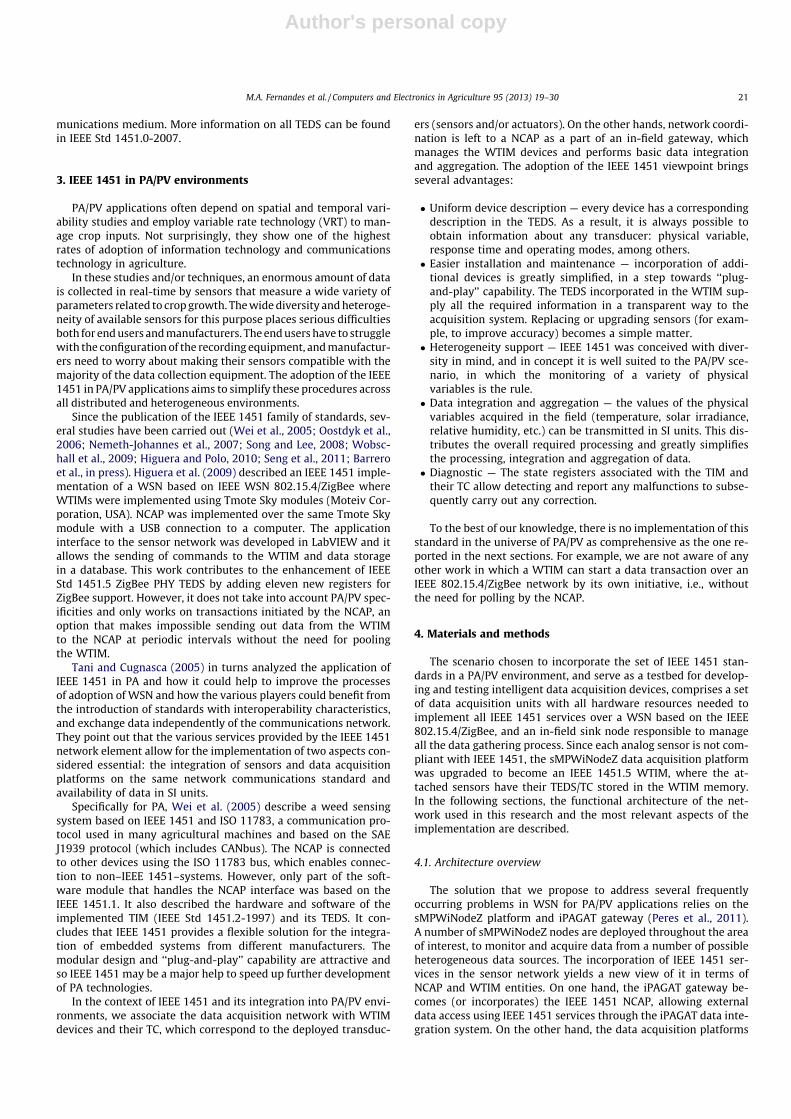
Fig. 6 illustrates the simplified state machine of the sMPWiNo- deZ application, illustrating the relationship between IEEE 1451 states, IEEE 802.15.4 /ZigBee management and power management.
After hardware initializatio n, it is necessary to search for anIEEE 802.15.4/Zig Bee network and connect to its coordinator.Afterwards, all IEEE 1451 layers can be initiated in the state WTIM-initializ ation . During this state, the IEEE 1451.0 and IEEE 1451.5 services are configured and all existing TC are checked and added to the data structure of the IEEE 1451.0 layer. This pro- cess involves the initializatio n of the state registers , attributes, aswell as reading and verification of the TEDS for all WTIM’s and their TC. In its normal operation, the WTIM periodically comes out from WTIMSleep state, checks the available energy and ifpassed it goes to the WTIMActive state during which the sMPWi- NodeZ can receive command messages from the NCAP. The TCassociated with each sensor uses a free running sampling mode and the data transmis sion mode has been set to streaming at fixedintervals. This configuration enables the autonomous sending ofreadings to the NCAP at regular intervals, without the need for any NCAP polling. If requests from the NCAP are pending, these are processed as soon as the WTIM enters its active state.
4.4. The iPAGAT gateway and NCAP services
We consider the iPAGAT to be the key element of the proposed architecture in Fig. 2, since it performs a set of in-field operation sand manages simultaneou sly a set of devices for heteroge neous data gathering. As such, in addition to all the services needed tocreate a distribut ed IEEE 1451 system, the iPAGAT implements a
set of additional services available to level 3, referred to, in this work, as the farm managemen t level.
The iPAGAT can be remotely accessed through the services pro- vided by its embedded data integration system for gateway man- agement , WSN monitoring and configuration. In addition, itprovides access to IEEE 1451 NCAP services, such as WTIM discov- ery, TEDS management, transduc er access, transducer manage- ment and WSN collected data. The data integration system also enables data queries to the NCAP data as well as iPAGAT aggre- gated data. It is also possible to monitor each WSN node including traffic, link quality indicator, and available energy using NCAP services.
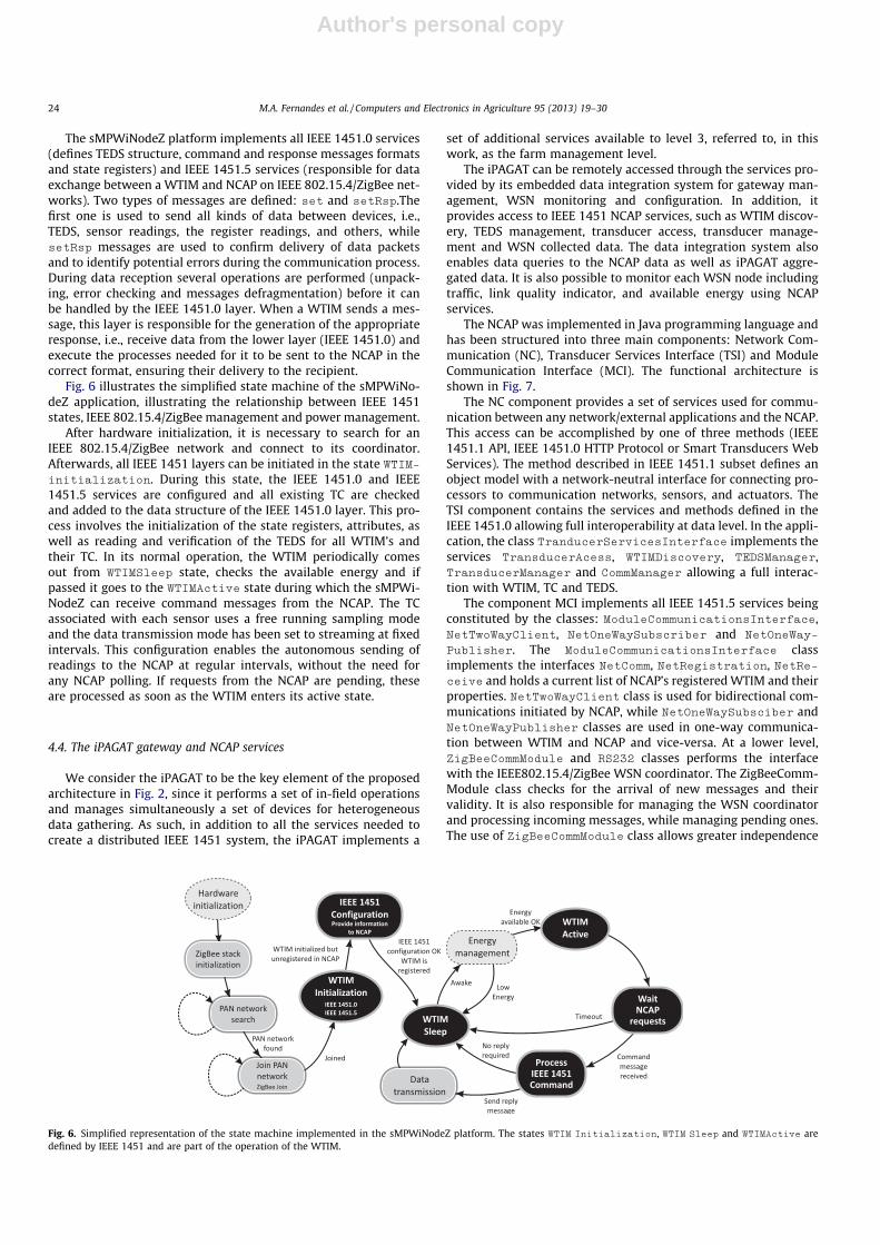
The NCAP was implemented in Java programmin g language and has been structured into three main components : Network Com- municati on (NC), Transducer Services Interface (TSI) and Module Communi cation Interface (MCI). The functional architecture isshown in Fig. 7.
The NC component provides a set of services used for commu- nication between any network/external applicati ons and the NCAP.This access can be accomplished by one of three methods (IEEE1451.1 API, IEEE 1451.0 HTTP Protocol or Smart Transducers Web Services). The method described in IEEE 1451.1 subset defines anobject model with a network- neutral interface for connectin g pro- cessors to communicati on networks , sensors, and actuators. The TSI component contains the services and methods defined in the IEEE 1451.0 allowing full interoperab ility at data level. In the appli- cation, the class TranducerServi cesInterf ace implements the services TransducerAces s, WTIMDiscovery, TEDSManager,Transduce rManager and CommManag er allowing a full interac- tion with WTIM, TC and TEDS.
The component MCI implements all IEEE 1451.5 services being constituted by the classes: ModuleCom municationsInt erface ,NetTwoWay Client , NetOneWay Subscriber and NetOneWay-
Publisher. The ModuleCom municatio nsInterface classimpleme nts the interfaces NetComm, NetRegist ration , NetRe-ceive and holds a current list of NCAP’s registered WTIM and their propertie s. NetTwoWay Client class is used for bidirectional com- municati ons initiated by NCAP, while NetOneWaySubsc iber andNetOneWay Publisher classes are used in one-way communi ca- tion between WTIM and NCAP and vice-versa. At a lower level,ZigBeeCom mModule and RS232 classes performs the interface with the IEEE802.15.4/Z igBee WSN coordina tor. The ZigBeeCo mm- Module class checks for the arrival of new messages and their validity. It is also responsible for managing the WSN coordinator and processing incoming messages, while managing pending ones.The use of ZigBeeCom mModule class allows greater independen ce
Fig. 6. Simplified representation of the state machine implemented in the sMPWiNodeZ platform. The states WTIM Initialization , WTIM Sleep and WTIMActive are defined by IEEE 1451 and are part of the operation of the WTIM.
24 M.A. Fernandes et al. / Computers and Electronics in Agriculture 95 (2013) 19–30
Author's personal copy
between the MCI component and radio technology adopted. The RS232 class consists of two separate processes responsible for receiving and sending messages to and from the WSN coordinator through an RS232 serial interface. In Section 5, these events are illustrated.
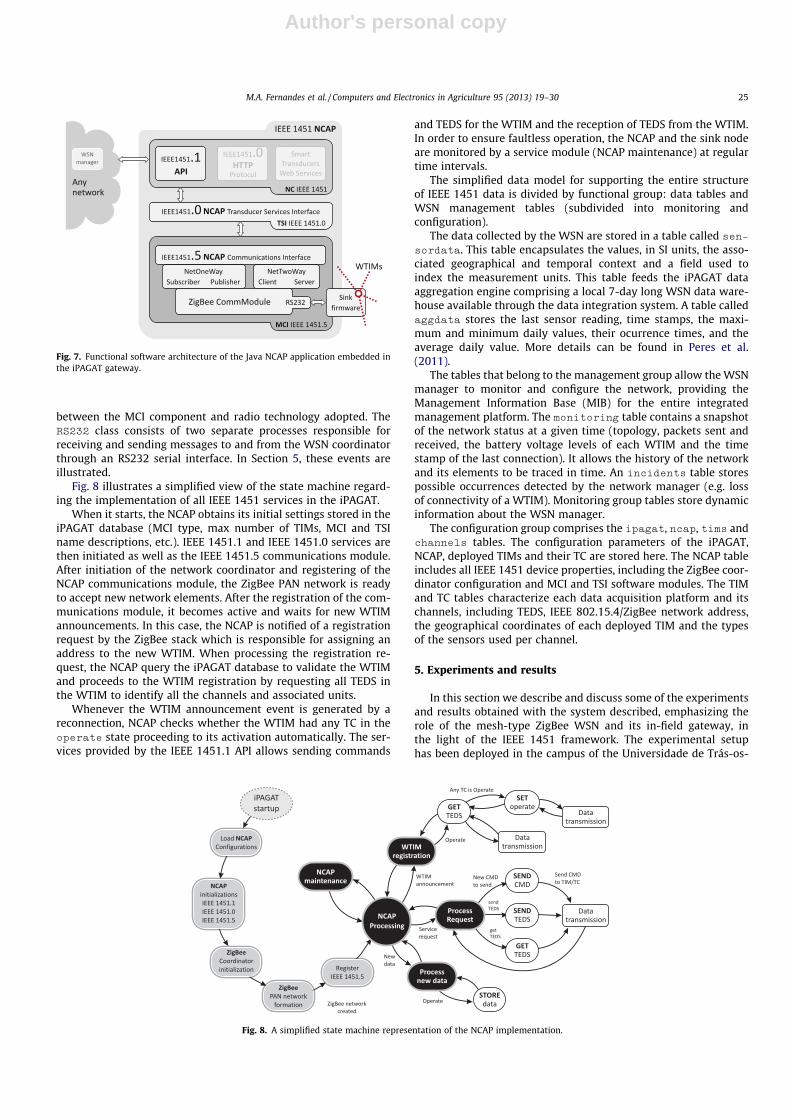
Fig. 8 illustrates a simplified view of the state machine regard- ing the implementation of all IEEE 1451 services in the iPAGAT.
When it starts, the NCAP obtains its initial settings stored in the iPAGAT database (MCI type, max number of TIMs, MCI and TSI name descriptions, etc.). IEEE 1451.1 and IEEE 1451.0 services are then initiated as well as the IEEE 1451.5 communi cations module.After initiation of the network coordinator and registering of the NCAP communications module, the ZigBee PAN network is ready to accept new network elements . After the registration of the com- munications module, it becomes active and waits for new WTIM announcement s. In this case, the NCAP is notified of a registrati onrequest by the ZigBee stack which is responsib le for assigning anaddress to the new WTIM. When processing the registration re- quest, the NCAP query the iPAGAT database to validate the WTIM and proceeds to the WTIM registration by requesting all TEDS inthe WTIM to identify all the channels and associated units.
Whenever the WTIM announcement event is generate d by areconnectio n, NCAP checks whether the WTIM had any TC in the operate state proceeding to its activation automaticall y. The ser- vices provided by the IEEE 1451.1 API allows sending commands
and TEDS for the WTIM and the reception of TEDS from the WTIM.In order to ensure faultless operation, the NCAP and the sink node are monitored by a service module (NCAP maintenanc e) at regular time intervals.
The simplified data model for supportin g the entire structure of IEEE 1451 data is divided by functional group: data tables and WSN management tables (subdivided into monitoring and configuration).
The data collected by the WSN are stored in a table called sen-sordata. This table encapsulates the values, in SI units, the asso- ciated geographical and temporal context and a field used toindex the measurement units. This table feeds the iPAGAT data aggregat ion engine comprising a local 7-day long WSN data ware- house available through the data integrati on system. A table called aggdata stores the last sensor reading, time stamps, the maxi- mum and minimum daily values, their ocurrence times, and the average daily value. More details can be found in Peres et al.(2011).
The tables that belong to the managemen t group allow the WSN manager to monitor and configure the network, providing the Managem ent Informati on Base (MIB) for the entire integrated managemen t platform. The monitorin g table contains a snapshot of the network status at a given time (topology, packets sent and received, the battery voltage levels of each WTIM and the time stamp of the last connectio n). It allows the history of the network and its elements to be traced in time. An incidents table stores possible occurrences detected by the network manager (e.g. loss of connectivity of a WTIM). Monitoring group tables store dynamic informat ion about the WSN manager.
The configuration group comprise s the ipagat, ncap, tims andchannels tables. The configuration parameters of the iPAGAT,NCAP, deployed TIMs and their TC are stored here. The NCAP table includes all IEEE 1451 device properties, including the ZigBee coor- dinator configuration and MCI and TSI software modules. The TIM and TC tables characterize each data acquisition platform and its channels, including TEDS, IEEE 802.15.4/Zig Bee network address,the geographical coordinates of each deployed TIM and the types of the sensors used per channel.
5. Experim ents and results
In this section we describe and discuss some of the experiments and results obtained with the system described , emphasizi ng the role of the mesh-type ZigBee WSN and its in-field gateway, inthe light of the IEEE 1451 framework. The experimental setup has been deployed in the campus of the Universidad e de Trás-os-
Fig. 8. A simplified state machine representation of the NCAP implementation.
Fig. 7. Functional software architecture of the Java NCAP application embedded inthe iPAGAT gateway.
M.A. Fernandes et al. / Computers and Electronics in Agriculture 95 (2013) 19–30 25
Author's personal copy
Montes e Alto Douro, Vila Real, Portugal, since May 2009. In refer- ence to the present paper, it consists of six nodes, one of which isthe NCAP (iPAGAT). The remaining nodes are WTIMs (sMPWiNo-deZ). At the ZigBee network level, four devices operate as end-de- vices and one device as a router. Fig. 9 illustrates all devices in the WSN.
The WTIMs were fitted with four TC sensors and four embedded TC actuators to configure the period of time between data acquisi- tions. The TC includes a temperature sensor LM50B, the battery voltage, the solar irradiance obtained through the solar panel and a channel used to transmit management data (battery voltage, Link Quality Indicator (LQI), bytes sent/received , parent and status bits)to the NCAP. In order for the sMPWiNodeZ platform to operate as aWTIM, we configured it with the appropriate MetaTEDS, Xdcr-
Name and PHYTEDS. For each of the TC, the corresponding ChanT-EDS and XdcrName were also configured, with the help of the TEDSMan ager application (Matos et al., 2012 ).
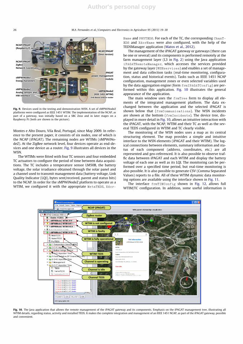
The managemen t of the iPAGAT gateway or gateways (there can be one or several) and its components is performed remotely at the farm managemen t layer (L3 in Fig. 2) using the Java application iPAGATRem oteManage r, which accesses the services provided by the gateway layer (WSNservices) and enables a set of manage- ment and data collection tasks (real-time monitoring, configura-tion, status and historical events). Tasks such as IEEE 1451 NCAP configuration, management zones or even selected variables used by the data aggregation engine (form frmIPAGAT Config ) are per- formed within this application. Fig. 10 illustrates the general appearan ce of the application.
The main window uses the frmTree form to display all ele- ments of the integrated managemen t platform. The data ex- changed between the application and the selected iPAGAT isshown below that (frmCommun ications ). The WSN incidents are shown at the bottom (frmIncide nts ). The device tree, dis- played in more detail in Fig. 10, allows an intuitive interaction with the iPAGAT, with the NCAP, WTIM and their TC as well as the sev- eral TEDS configured in WTIM and TC clearly visible.
The monitoring of the WSN nodes uses a map as its central structuring element. The map provides a simple and intuitive interface to the WSN elements (iPAGAT and their WTIM). The log- ical connections between elements, summary information and sta- tus of each component (address, coordinates , etc.) are all represented and geo-referenced . It is also possible to observe traf- fic data between iPAGAT and each WTIM and display the battery voltage of each one as well as its LQI. The monitoring can be per- formed over a specified time period, but real-time monitoring isalso possible. It is also possible to generate CSV (Comma Separated Values) reports to a file. All of these WTIM dynamic data monitor- ing options are available using the interface shown in Fig. 11.
The interface frmTIMConfig shown in Fig. 12, allows full WTIM/TC configuration. In addition, some useful information is
Fig. 9. Devices used in the testing and demonstration WSN. A set of sMPWiNodeZ platforms were configured as IEEE 1451 WTIM. The implementation of the NCAP, aspart of a gateway, was initially based on a SBC Zeus and in later stages on aRaspberry Pi (both are shown in the picture).
Fig. 10. The Java application that allows the remote management of the iPAGAT gateway and its components. Emphasis on the iPAGAT management tree, illustrating all WTIM details, regarding status, activity and installed TEDS. It makes the complete integration and management of an IEEE 1451 NCAP, as part of the iPAGAT gateway, possible and convenient.
26 M.A. Fernandes et al. / Computers and Electronics in Agriculture 95 (2013) 19–30

Author's personal copy
Fig. 11. Real time data visualization interface for each WTIM. Traffic bytes, WTIM battery voltage levels as well as LQI are displayed. Data can also be exported to other officetools.
Fig. 12. Java interface used to configure all WTIM parameters.
M.A. Fernandes et al. / Computers and Electronics in Agriculture 95 (2013) 19–30 27

Author's personal copy
presented such as WTIM network address, location and date of the last connection, and TEDS/TC of selected WTIM. It is also possible to display all mandator y IEEE 1451.0 (MetaTEDS, XdcrName,ChanTEDS) and IEEE 1451.5 (PHYTEDS) TEDS. There is an addi- tional feature that we have found useful: it is possible to send TEDS for a specific WTIM and/or TC; activate (operate state) or deacti- vate (idle state) a specific channel, or even change the TC acqui- sition time period.
In the case of sensors that may be added by the user to a sMPW- iNodeZ platform, their TEDS and TC may be remotely configuredusing the iPAGATRem oteManage r and download ed to the WTIM through the network or be programmed through the TEDSManager tool.
Two distinct transactions types between the NCAP and a WTIM may occur. The transmission of a command to each WTIM for con- figuration or actuation purposes is one type. The other type is the periodic transmission of acquired data by each WTIM, an impor- tant capability because it avoids the need for the NCAP to poll each WTIM in the network (as described by Higuera et al. (2009)).
Fig. 13 illustrate s in a precise way the timing of the sequence ofoperations needed to send a command from the NCAP to a WTIM following the IEEE 1451.0 specification. Examples of such remote configuration command s are WTIM configuration, calibration, en- abling/disabl ing TC and setting acquisition period. For instance,in order to instruct a sensor to perform periodic readings, one sim- ply needs to activate its TC by sending an operate command tothe WTIM. Besides the associated TC/sensor, an embedded pair ofvirtual TC/actuator was created as an IEEE 1451.0 control group.This procedure enables the setting of the sampling acquisition per- iod using the same procedure, i.e., by sending a command to the embedded virtual actuator where the paramete r is the desired time period. This is an important improvement because it normal- izes all WSN related procedures , an important step towards interoperab ility.
Once configured, the TC proceeds to trigger sensor readings atperiodic time intervals and sends each sample value to the NCAP without any need for polling. The diagram in Fig. 14 illustratesthe process of receiving a new sensor data from the WTIM. Once received, decoded and processed by the several NCAP modules,data are stored in the iPAGAT database through the module WSNmanag er.
The command /response pairs and message formats are de- scribed in Fig. 15 as an example when a temperature sensor con-
nected to a WTIM sends data with a sampling interval set to300 s. The first three pairs describe WTIM configuration operations and the last one illustrates the transmis sion of the sensor reading to the NCAP. If the sensor is associated with channel 1 (TC) ofthe WTIM, then, to start collecting data, the correspondi ng TC must be activated, that is, placed in the operate state. To change the state of the TC, a sequence of events must take place. Among other functions, this allows switchin g on and off the sensor, define the period of time between readings, and, in the case of an actuator,to change its output status.
Fig. 13. Operations sequence for sending a command from NCAP to a WTIM accordingly to IEEE 1451.0 specification. This sequence is used, for instance, toprogram the TC of a WTIM to operate on every sampling period.
Fig. 14. Operations sequence for receiving incoming data from a sensor attached toWTIM operating in the free running mode. For instance, this sequence is used toretrieve data from a WTIM that is transmitting temperature readings every 5 min.
Fig. 15. Command/response pairs and message formats used to describe WTIM’s TCconfiguration operations. The last pair illustrates the transmission of a sensor reading to the NCAP without the need of NCAP polling.
28 M.A. Fernandes et al. / Computers and Electronics in Agriculture 95 (2013) 19–30

Author's personal copy
These sequences of events clearly show that normalization ofthe command sending procedures and data reception by all net- work elements is an enormous advantage that follows from the application of the IEEE 1451 family of standards. The implementa- tion of TC in the WTIM considerably simplifies the tasks of design- ing, implementi ng and managing heterogeneous sensor networks ,such as those used in PA/PV.
The implementati on of the NCAP as part of iPAGAT made avail- able all of its services and potential . An example is the iPAGAT alarm or warning system. We explored it to implement a message service that allows the automatic sending of e-mail reports about the iPAGAT activities. This may include issues reported by the 1451 subsystem or ZigBee. Fig. 16 illustrates two such warning messages: one is triggered when the iPAGAT is powered up, the other is when the communication with a WTIM is lost.
6. Discussion
The IEEE 1451 family of standards is very comprehens ive but also very complex, a fact that has not always helped to make itquickly and widely adopted. However, despite the perceived com- plexity of these standards, they do provide a number of important advantages which make the impleme ntation effort worthwhile.
We have already discussed some of the IEEE 1451 advantag es inthe context of PA/PV. The authors have a long term interest in PA/ PV, mainly targeted to the Douro region in the Northeast of Portu- gal, one of the oldest (if not the oldest) demarcated wine-produc- ing regions in Europe. The unique characterist ics of the region, the technical challenges set by PA/PV and its important benefits (envi-ronmental, economical, etc.) have made our task both difficult and interesting.
This article is one in a series of works that the group has carried out (Morais et al., 2008a,b; Cunha et al., 2010; Peres et al., 2011 ).The technological solutions that we have described provide added value in PA/PV, particular ly in reference to the study of variability in PA/PV practices. We have considered topics ranging from power issues (energy harvesting, power managemen t, etc.) to networki ngissues (overall architecture, software, hardware). More recently,increasingly aware of the complexi ty and costs hidden in the deployment, managemen t and maintenance of heterogeneous WSN, we came to appreciate normalized procedures that could
simplify these tasks. This work is considered by its authors as the first practical, full IEEE 1451 application in PA/PV and a privileged framewor k under which new applications can be easily tried.
As far as we know, this is the first time that the IEEE 1451 stan- dards are incorporate d in already existing devices, as a way of cre- ating an open framewor k for interoperabilit y. Although analog sensors are not intrinsically compatib le with the IEEE 1451 stan- dards, the combination iPAGAT/NCA P allows the creation of smart,easy-to-con figure systems. Each wireless data acquisition platform becomes a sensor node (WTIM) with a smart TC, replacing multiple isolated sensors. The addition or removal of sensors or actuators ina totally automatic way is still limited by the WTIM hardware, but with products in which sensors are already embedde d, the entire configuration process can proceed according to the IEEE 1451 stan- dard. This allows for the development of software components (drivers) for sensor networks. As a result of the lessons learned from this work, we are now consideri ng the specification of aninterface of reconfigurable hardware under the command of the WTIM, which might allow the connection of an analog sensor and the remote configuration of the system for its incorporati on.
7. Conclusi ons
One of the conclusions that can be extracted from our study isthat IEEE 1451 is powerful when correctly integrated in devices that acquire, store and process heterogeneous data. The incorpora- tion of IEEE 1451 services in the data acquisition devices allows the use of TEDS in all sensors, significantly simplifying the configura-tion procedures. The selection, at the NCAP level, of the sensors associate d with each WTIM is enough to make ‘‘plug-and-p lay’’ areality.
In our implementati on, we have found that the module that interacts with the transducers is very important. It complemen tsthe work very well since it allows the automatic configuration ofthe interfaced devices. Depending on the TEDS of the transduc er,the hardware of the acquisition platform can be configured toaccommodate the selected sensor. We have found that this prop- erty is particularly useful and important, given the wide range ofoutput types that sensors in PA/PV may exhibit.
Another important conclusion extracted from this work is that afull impleme ntation of the complex set of IEEE 1451 standards is
Fig. 16. Examples of automatic warning messages sent by iPAGAT and triggered when specific conditions occur. The messages can be sent by e-mail.
M.A. Fernandes et al. / Computers and Electronics in Agriculture 95 (2013) 19–30 29
Author's personal copy
possible for WSN based on 802.11, 802.15.4, Bluetooth, ZigBee, and 6LoWPAN as cited in the references, but may be difficult for today’s ultra-low power embedded system technology. This may change inthe near future as the technology evolves. However, the standard- ization is still crucial for the managemen t of heteroge neous data.The simplicity in handling the data collected by WSN that support IEEE 1451 over IEEE 802.15.4/ZigBee networks shows very clearly that the IEEE 1451 family of standards is very well suited to the universe of PA/PV and to meet its needs.
Acknowledgeme nts
The authors would like to acknowledge the Portuguese Founda- tion of Science and Technology (FCT) that partially sponsors this research work through the scholarshi p reference SFRH/BD/3875 9/2007.
References
Barrero, F., Guevara, J.A., Vargas, E., Toral, S., Vargas, M., in press. Networked transducers in intelligent transportation systems based on the IEEE 1451 standard. Computer Standards & Interfaces, (Corrected Proof).
Camilli, A., Cugnasca, C.E., Saraiva, A.M., Hirakawa, A.R., Corrêa, P.L., 2007. From wireless sensors to field mapping: anatomy of an application for precision agriculture. Computers and Electronics in Agriculture 58 (1), 25–36.
Chen, C., Helal, A., Julu 2009. Device integration in SODA using the device description language. In: Ninth Annual International Symposium onApplications and the Internet, 2009. SAINT ’09. pp. 100–106.
Chen, C., Helal, S., 2008. Sifting Through the Jungle of Sensor Standards. IEEE Pervasive Computing 7 (4), 84–88.
Cunha, C.R., Peres, E., Morais, R., Oliveira, A.A., Matos, S.G., Fernandes, M.A., Ferreira,P., Reis, M., 2010. The use of mobile devices with multi-tag technologies for anoverall contextualized vineyard management. Computers and Electronics inAgriculture 73 (2), 154–164.
Higuera, J., Polo, J., February 2010. Understanding the IEEE 1451 standard in6loWPAN sensor networks. In: Sensors Applications Symposium (SAS), 2010 IEEE, pp. 189–193.
Higuera, J., Polo, J., Gasulla, M., February 2009. A Zigbee wireless sensor network compliant with the IEEE1451 standard. In: Sensors Applications Symposium,2009. SAS 2009. IEEE. pp. 309–313.
Hu, P., Robinson, R., Indulska, J., December 2007. Sensor standards: overview and experiences. In: 3rd International Conference on Intelligent Sensors, Sensor Networks and Information, 2007. ISSNIP 2007, pp. 485–490.
Lee, K., 2008. From the editor’s bench – smart and wireless sensor standards for distributed measurements. IEEE Instrumentation Measurement Magazine 11(2), 6.
Matos, S., Fernandes, M.A., López, J.A., Soto, F., Reis, M.J.C.S., Morais, R., July 2012. An interactive GUI tool to create and validate IEEE 1451 Smart Sensors TEDS. In: Proceedings of de Seminario Anual de Automática,Electrónica Industrial e Instrumentación 2012, SAAEI’2012. Guimarães,Portugal, pp. 510–515.
Morais, R., Fernandes, M.A., Matos, S.G., Serôdio, C., Ferreira, P., Reis, M., 2008a. AZigBee multi-powered wireless acquisition device for remote sensing applications in precision viticulture. Computers and Electronics in Agriculture 62 (2), 94–106.
Morais, R., Matos, S.G., Fernandes, M.A., Valente, A.L.G., Soares, S.F.S.P., Ferreira,P.J.S.G., Reis, M.J.C.S., 2008b. Sun, wind and water flow as energy supply for small stationary data acquisition platforms. Computers and Electronics inAgriculture 64, 120–132.
Nemeth-Johannes, J., Sweetser, V., Sweetser, D., September 2007. Implementation ofan IEEE-1451.0/1451.5 compliant wireless sensor module. In: Autotestcon,2007 IEEE. pp. 364–371.
Oostdyk, R., Mata, C., Perotti, J., 2006. A Kennedy Space Center implementation ofIEEE 1451 networked smart sensors and lessons learned. In: Aerospace Conference, 2006 IEEE. pp. 1–20.
Peres, E., Fernandes, M.A., Morais, R., Cunha, C.R., López, J.A., Matos, S.R., Ferreira, P.,Reis, M., 2011. An autonomous intelligent gateway infrastructure for in-fieldprocessing in precision viticulture. Computers and Electronics in Agriculture 78(2), 176–187.
Seng, R., Lee, K., Song, E., May 2011. An implementation of a wireless sensor network based on IEEE 1451.0 and 1451.5 6LoWPAN standards. In:Instrumentation and Measurement Technology Conference (I2MTC), 2011 IEEE. pp. 1–6.
Song, E., Lee, K., 2007. Smart transducer web services based on the IEEE 1451.0 standard. In: Instrumentation and Measurement Technology Conference Proceedings, 2007. IMTC 2007. IEEE, pp. 1–6.
Song, E., Lee, K., 2008. Sensor Network based on IEEE 1451.0 and IEEE p1451.2- RS232. In: Instrumentation and Measurement Technology Conference Proceedings, 2008. IMTC 2008.. IEEE, pp. 1728–1733.
Tani, F.K., Cugnasca, C.E., 2005. Agriculture and the IEEE 1451 smart transducer interface standard. In: EFITA/WCCA 2005 JOINT CONFERENCE, Proceedings.University of Trás-os-Montes and Alto Douro, pp. 1341–1348.
Wei, J., Zhang, N., Wang, N., Lenhert, D., Neilsen, M., Mizuno, M., 2005. Use of the ‘‘smart transducer’’ concept and IEEE 1451 standards in system integration for precision agriculture. Computers and Electronics in Agriculture 48 (3),245–255.
Wiczer, J., Lee, K., 2005. A Unifying Standard for Interfacing Transducers toNetworks — IEEE 1451.0. Presented at ISA Expo 2005, Chicago, IL.
Wobschall, D., Stepanenko, A., Maykiv, I., Kochan, R., Sachenko, A., Kochan, V.,2009. A multi-port serial NCAP using the I EEE 1451 smart transducer standard. In: Sensors Applications Symposium, 2009. SAS 2009. IEEE, pp.293–297.
30 M.A. Fernandes et al. / Computers and Electronics in Agriculture 95 (2013) 19–30