a framework for early design and prototyping of service ... · a framework for early design and...
TRANSCRIPT

A framework for early design and prototyping ofservice-oriented applications with design patterns
Steven Capelli, Patrizia Scandurra∗
Universita degli Studi di Bergamo, Dept. of Managment, Information and ProductionEngineering, Dalmine (BG), Italy
Abstract
Service-oriented computing is playing an important role in several domains. To-day the biggest shift in mainstream design and programming is toward service-oriented applications. However, the service paradigm raises a bundle of problemsthat did not exist in traditional component-based development where abstrac-tion, encapsulation, and modularity were the only main concerns. Due to theirdistributed, dynamic, and heterogeneous nature, service-oriented software ap-plications require us to discover, document, and share new design patterns atthe service- and architecture- level. Moreover, service-oriented applications arehard to design and validate, and demand for new foundational theories, model-ing notations and analysis techniques.
In line to such a vision, this article presents a framework, called SCA-PatternBox, to design and prototype service-oriented applications with designpatterns. The framework relies on the OASIS standard Service Component Ar-chitecture (SCA) and on SCA component implementation types, such as SCA-Java, for supporting an “implementation-oriented” approach to service-orientedarchitecture modeling and to the definition and instantiation of design patterns.Moreover, in order to provide formally verified design patterns, SCA-PatternBoxallows the formal specification and analysis of the functional behavioral aspectsof a design pattern using a formal service specification language called SCA-ASM (Service Component Architecture - Abstract State Machine). As majorevaluation of the framework, two case studies and lessons learned are presented.A final comparison of existing design pattern languages is also reported.
Keywords: service modeling and prototyping, design pattern languages,service component architectures, formal pattern specification
∗Corresponding author.Email addresses: [email protected] (Steven Capelli),
[email protected] (Patrizia Scandurra)
Preprint submitted to Elsevier and published in COMPUTER LANGUAGES, SYSTEMS & STRUCTURES

1. Introduction
Today the biggest shift in mainstream programming and design is towardservice-oriented applications. Service-oriented applications are playing so faran important role in several domains (e.g., information technology, health care,robotics, defense and aerospace, to name a few). Cloud service providers, in par-ticular, are expanding their offerings to include the entire traditional IT stack,ranging from foundational hardware and platforms to application components,software services, and whole software applications.
Service-oriented Computing (SoC) is a paradigm for developing loosely-coupled, interoperable, dynamic systems relying on the basic unification prin-ciple that “everything is a service”. Services are intended as loosely-coupledautonomous and heterogeneous1 computational components that are offered byservice providers in a distributed environment via publish/discovery protocols.The architectural foundation for SOC is provided by the Service-Oriented Ar-chitecture (SOA), which states that applications expose their functionality asservices in a uniform and technology-independent way such that they can bediscovered and invoked over a network and clouds.
Such a paradigm shift relies on interface-based design, composition, andreuse; but, differently from traditional component-based design where abstrac-tion, encapsulation, and modularity were the only main concerns, the serviceparadigm raises a bundle of problems which did not exist previously. Early de-signing, prototyping, and testing of the functionality of such assembled service-oriented applications is hardly feasible since services are discoverable, loosely-coupled, and heterogeneous components that can only interact with others oncompatible interfaces. Moreover, this paradigm shift requires us to discover,formally define, document, and share new design patterns. A SOA design pat-tern provides a solution in support of successfully applying service orientationand establishing a quality service-oriented architecture. SOA patterns describecommon architectures, implementations, and their areas of application to helpin the planning, implementation, deployment, management, and maintenanceof complex systems. According to the SOA principles[1], design patterns play afundamental role to support the engineering of service-oriented applications andthe attainment of the strategic goals of SoC. In particular, a special emphasishas been put so far on the development of a catalog of SOA design patterns2.
In line to such a vision, this article proposes a framework, SCA-PatternBox,for modeling service-oriented applications with design patterns. The frameworkrelies on the OASIS open standard Service Component Architecture (SCA) [2]as modeling language for heterogeneous service assembly in a technology ag-nostic way, and on the Java implementation for SCA. A supporting prototypetool based on the Eclipse environment is also available at [34]. It was devel-oped by extending the Eclipse plug-in PatternBox [3], an existing design pat-
1Services are in general, heterogeneous, i.e. they differ in their implementation/middlewaretechnology.
2http://www.soapatterns.org/
2

tern editor for Java code, and by integrating it with the Eclipse-based SCAComposite Designer and the SCA runtime platform Tuscany [4]. Through anXML template-based mechanism, SCA-PatternBox allows the definition of de-sign patterns and their instantiation from a scratch SCA design to be furthercustomized depending on the application needs, or from an SCA component as-sembly of an existing service-oriented application to generate automatically thecorresponding compound SCA component assembly and the SCA-Java skeletoncode (indeed, Java classes and interfaces with appropriate annotations for SCA).The template-based approach for the pattern instantiation and code generationmakes SCA-Patterbox higher usable than wizard-based approaches where youhave to complete the whole design pattern instance at once. Moreover, SCA-PatternBox can be easily extended. New design patterns and code generatorscan be introduced by defining new XML templates depending on the targetimplementation platform and application domain.
Since patterns have two complementary aspects (structural and behavioral),for patterns that have a significant behavioral aspect, it is necessary to under-stand how service components collaborate to achieve the expected behavior.To this purpose, in addition to a Java-like implementation of design patterns,SCA-PatternBox allows also the formal specification and analysis of the func-tional behavioral aspect of design patterns using a formal service specificationlanguage called SCA-ASM [6, 7]. SCA-ASM is based on the formal method Ab-stract State Machine [8] that allows the definition of executable and state-basedspecifications of systems behavior. The main goal is to provide formally verifieddesign patterns by producing precise and unambiguous functional descriptionsof design patterns in SCA-ASM and then to validate and verify these formalspecifications (e.g. through simulation and model checking).
The proposed framework offers several advantages with respect to the cur-rent state of art (see Sect. 6 for a detailed comparison with related works). Inthe literature, design patterns are typically described using a combination ofnatural language, UML class and sequence diagrams, and program code (seerelated work in Sect. 6.1). Such descriptions lack design pattern-specific visualformalisms, leading to pattern descriptions that are hard to understand, hardto incorporate into tool support, and therefore hard to be machine-processablein order to automate their instantiation and application in the current designand then in the software code. The proposed framework was conceived insteadwith automation in mind and to this purpose a template-based approach wasadopted. The purpose of this work is to facilitate the construction of a service-oriented application and to help engineers understand alternative means forachieving alternative architectures in the applications design and code. More-over, existing approaches are specific to object-oriented system design and donot address SOA design patterns. Instead, our approach addresses also designpatterns related to the SOA domain. Finally, some existing approaches that usea mathematical formalism for defining design patterns formally require strongmathematical background to the user and lack of good tool support. Basedon the practical and scientifically well-founded ASM formal method, SCA-ASMmodels are instead executable and without mathematical overkill. SCA-ASM
3

allows modeling both structure and behavior of service components in a uniqueframework integrating architectural and behavioral views. By exploiting theprototyping/validation environment for SCA-ASM [7], patterns and componentscan be executed already at high level of formalization, without caring about im-plementation details. Early validation by model simulation is a great meansfor evaluating architectural choices and alternative designs with limited imple-mentation effort. The mathematical foundation of the method also facilitatesreasoning about component behavior in order to guarantee their correctness.
A first prototype of the SCA-PatternBox environment was presented as atool demo at the Eclipse Italian workshop [9], while a preliminary overview ofthe framework was presented in [10]. This article extends these preliminaryworks in several aspects. First, this article provides a more accurate descriptionof the pattern definition language adopted by the SCAPatternBox frameworkand its use through concrete patterns examples. Formal analysis techniques sup-ported by SCAPatternBox for validating and verifying the functional behavioralaspects of patterns and applications are presented. The article introduces also asupporting methodology for a general and agile prototyping of a service-orientedapplication with the SCA-PatternBox framework, and illustrates the methodol-ogy through two case studies – the Order system and the Stock Trading System(STS). Lessons learned that we gained through our experience in developingthe case studies and that should be retained for future use are also reported.Moreover, a comparison of existing design pattern languages is also presentedaccording to some specific criteria.
The remainder of this article is organized as follows. Section 2 provides back-ground concepts on SCA, SCA-Java and SCA-ASM. Section 3 introduces theSCA-PatternBox language and alternative notations for editing design patternsand instantiating them automatically. Section 4 describes the SCA-PatternBoxframework and a supporting design/development methodology for prototyp-ing service-oriented applications with design patterns. Section 5 illustrates themethodology with two case studies and provides some lessons learned during thedevelopment of the framework and its use for the case studies. Section 6 surveysthe main existing design pattern languages and provides a comparison of themand of our proposed SCA-PatternBox language. Finally, Section 7 concludesthe article and sketches some future directions of our work.
2. Background concepts
Service Component Architecture (SCA) [2] is an XML-based componentmodel used to develop service-oriented applications independently from SOAplatforms and middleware programming APIs. SCA is also endowed with a vi-sual notation and supported by an Eclipse-based design tool and runtime plat-forms (like Apache Tuscany, FRAscaTI, IBM WebSphere Application ServerV7, etc.) for the development and deployment of service-oriented applications.
Fig. 1 shows an SCA composite (or assembly) as a composition of SCAcomponents. An SCA component is a piece of configured software that provides
4

Figure 1: An SCA composite (adapted from the SCA Assembly Model V1.00 spec.)
Figure 2: SCA-Java component shape
business functions (operations) for interaction with the outside world. This in-teraction is accomplished through: services that are externally visible functionsprovided by the component; references (functions required by the component)wired to services provided by other components; properties allowing for theconfiguration of a component implementation and bindings that specify accessmechanisms used by services and references according to some technology/pro-tocol (e.g., WSDL binding to consume/expose web services, JMS binding toreceive/send Java Message Service, etc.). Services and references are typed byinterfaces. An interface describes a set of related operations (or business func-tions) which as a whole make up the service offered or required by a component.The provider may respond to the requester of an operation with zero or moremessages. Message exchange may be synchronous or asynchronous.
The SCA-Java Component Implementation [2] defines how to implement anSCA component using Java. Fig. 2 shows the SCA component A of Fig. 1 and itsJava implementation class AImpl. Java annotations (@Property,@service,etc.)are used to augment Java classes with SCA concepts.
5

The SCA-ASM specification type [6, 7] complements the SCA componentmodel with the ASM model of computation to provide ASM-based formal andexecutable description of services internal behavior, orchestration and interac-tions. An open framework, the ASM toolset ASMETA (ASM mETA-modeling)[11, 12], based on the Eclipse/EMF platform and integrated with the SCA run-time Tuscany, is also available for editing, simulating, validating, and potentiallymodel checking SCA-ASM models [6, 7].
ASMs [8] are an extension of FSMs where states are arbitrary complex data(multi-sorted first-order structures) and the transition relation is specified byrules describing how functions change from one state to the next. The basicrule has the form of guarded update “if Cond then Updates” where Updates isa set of function updates of the form f(t1, . . . , tn) := t which are simultaneouslyexecuted when Cond is true. Rule constructors express parallel actions (par), se-quential actions (seq), iterations (iterate, while, recwhile), non-determinism (ex-istential quantification choose) and unrestricted synchronous parallelism (uni-versal quantification forall). Distributed computation is modeled by meansof multi-agent ASMs: multiple agents interact in a synchronous/asynchronousway, each executing a program specified by an ASM rule.
In SCA-ASM, a service-oriented component is an ASM endowed with (atleast) one agent (a business partner or role). Components’ agents interact withother agents by providing and requiring services. The service behaviors en-capsulated in an SCA-ASM component are captured by ASM transition rules.Fig. 3 shows the shape of the SCA-ASM component A of Fig. 1 and the cor-responding ASM modules for the provided interface AService (on the left) andthe skeleton of the component itself (on the right) using the textual notationASMETA/AsmetaL and the @annotations to denote SCA concepts. ASM ruleconstructors and predefined ASM rules (i.e., named ASM rules in a model li-brary) are used as SCA-ASM behavioral primitives. These rules are recalled inTable 1 by separating them according to the separation of concerns computa-tion, communication and coordination. In particular, communication primitivesprovide both synchronous and asynchronous interaction styles (corresponding,respectively, to the request-response and one-way interaction patterns of theSCA standard). Communication relies on a dynamic domain Message that rep-resents message instances managed by an abstract message-passing mechanism:components communicate over wires according to the semantics of the com-munication commands reported above and a message encapsulates informationabout the partner link and the referenced service name and data transferred.We abstract, therefore, from the SCA notion of binding3. Rules for fault/com-pensation handling are also supported [7].
3Indeed, we adopt the default SCA binding (binding.sca) for message delivering, i.e. theSOAP/HTTP or the Java method invocations (via a Java proxy) depending if the invokedservices are remote or local, respectively.
6

Figure 3: SCA-ASM component shape
3. The SCA-PatternBox pattern language
This section describes the SCA-PatternBox language supporting the specifi-cation of architectural design patterns and their instantiation into SCA assem-bly models of service-oriented applications. The section also provides concreteexamples of design patterns.
The SCA-PatternBox language consists of a metamodel (the abstract syn-tax ) providing a set of modeling constructs to define and reuse design patterns,and of XML-based notations (the concrete syntax ) for modeling design patternsolutions and solution instances within SCA models. The XML-based concretenotations are both human- and machine- comprehensible.
The SCA-PatternBox language can be used as a stand-alone modeling no-tation for design patterns or in conjunction with SCA to model design patterninstances within SCA assembly models of service-oriented applications. A de-sign pattern instance describes the relationships between the design patternelements modeled in the SCA-PatternBox language and the design elements(service-oriented components and interfaces) in the SCA assembly of a specificapplication.
The proposed language is intended to be used only to model the generalizedsolutions proposed by design patterns and facilitate their application and reuse.Further details, such as when the solution should be applied and consequencesof using the pattern, are not included. The SCA-PatternBox language has been
7

Table 1: SCA-ASM rule constructors for computation, coordination, communicationcomputation and coordination
Skip rule skip do nothingUpdate rule f(t1, . . . , tn) := t update the value of f at t1, . . . , tn to tCall rule R[x1, . . . , xn] call rule R with parameters x1, . . . , xnLet rule let x = t in R assign the value of t to x and then execute
RConditional it φ then R1 else R2 if φ is true, then execute rule R1,rule endif otherwise R2
Iterate rule while φ do R execute rule R until φ is trueSeq rule seq R1 . . . Rn endseq rules R1 . . .Rn are executed in sequence
without exposing intermediate updatesParallel rule par R1 . . . Rn endpar rules R1 . . .Rn are executed in parallelForall rule forall x with φ do R(x) forall x satisfying φ execute RChoose rule choose x with φ do R(x) choose an x satisfying φ and then execute
RSplit rule forall n ∈ N do R(n) split N times the execution of RSpawn rule spawn child with R create a child agent with program R
communicationSend rule wsend[lnk,R,snd ] send data snd to lnk in reference to rule R
(no blocking, no acknowledgment)Receive rule wreceive[lnk,R,rcv ] receive data rcv from lnk in reference to
R (blocks until data are received, no ack)SendReceive wsendreceive send data snd to lnk in reference to Rrule [lnk,R,snd,rcv ] waits for data rcv to be sent back (no ack)Reply rule wreply[lnk,R,snd ] returns data snd to lnk, as response of R
request received from lnk (no ack)
designed with automated tool support in mind. It is relatively easy to learn,particularly in conjunction with SCA.
3.1. Design pattern specification
Typically, an architectural design pattern describes components and detailstheir roles and interactions. All components together solve the problem thatthe pattern addresses.
Fig. 4 shows the SCA-PatternBox language’s metamodel capturing the veryessence of a design pattern independently of its domain. A design pattern inSCA-PatternBox is to be intended as an instance of this metamodel. Essen-tially, a design pattern (the class Pattern) defines roles (the class Role), roledependencies (the class Dependence), and an informal description (the attributecomment) in natural language. Roles are played by the participants of a patternsolution. A role has, among other things, an attribute type to tailor the typeof architectural design elements (a component or interface) that can play therole, a multiplicity (the attributes min and max) that constrains the numberof elements that can play the role, an attribute property to denote a set ofmandatory properties, and an attribute operation to denote a set of manda-tory service operations. The default multiplicity interval (min,max) in the classRole is 1..*, specifying that there must be at least one element playing the role.Dependencies are typically between a component role and a provided/required
8

Figure 4: SCA-PatternBox design pattern metamodel
interface role, but not necessarily. There can be also dependencies betweencomponents themselves to denote, for example, wires connecting a compositecomponent with a sub-component. In this last case the attribute type of the de-pendence is not present. This is enforced by the following OCL invariant (i.e.,a constraint that must always be met by all instances of a class) introducedwithin the context of the class Dependence:
context Dependence
inv targetRoleType: not self.type.isNull implies self.role.type=interface
Some other OCL constraints not reported here have been defined to constrainthe number of valid instances of this metamodel. These constraints are embed-ded in the SCAPatternBox editor and checked during pattern instantiation.
As concrete textual syntax associated to the metamodel, a pattern is de-fined in an XML file conforming to a DTD manifest.dtd. Code 1 reportsthe XML file for the definition of a service interaction micro-pattern4 calledRequest-Response. In this interaction schema, a component ClientRequest-
Response invokes a service of the component Server and waits for the resultto be returned before continuing with its processing. Request-response is thedefault mode of invoking a service in a synchronous way.
As complementary concrete syntax, a pattern can be also defined in termsof an SCA assembly model thus exploiting the SCA graphical notation. ThisSCA assembly consists of service components and reference-to-service wires cor-responding, respectively, to roles and role dependencies. Exploiting the SCA(graphical) notation provides a much higher expressive power, but it is tied toa specific design language. Fig. 5 shows the SCA assembly for the Request-Response micro-pattern.
4Micro-patterns are prime candidates of “units of design” to look for and are the “basis”of more complex SOA patterns.
9

Code 1: Request-Response micro-pattern
1 <!DOCTYPE pattern SYSTEM ”manifest.dtd”>2 <pattern id=”requestresponse” name=”RequestResponse”3 topCategorie=”SCA” subCategorie=”Micro Pattern”>4 <role name=”RequestResponseService” min=”1” max=”1” type=”Interface” operation=”request”>5 <comment>6 <li>defines a service interface.</li>7 </comment></role>8 <role name=”Server” min=”1” max=”1” type=”Component”>9 <comment>
10 <li>implements the RequestResponseService interface.</li></comment>11 <dependence role=”RequestResponseService”/ type=”provided”></role>12 <role name=”ClientRequestResponse” min=”1” max=”1” type=”Component”>13 <comment>14 <li> maintains a reference to a RequestResponseService;</li>15 <li> makes a request to a RequestResponseService and waits for the result. </li></comment>16 <dependence role=”RequestResponseService” type=”required”/></role>17 </pattern>
Figure 5: Request-Response micro-pattern in SCA
3.2. Design pattern instantiation
Instantiating a design pattern means creating a new piece of design called“design pattern instance” by mapping the design elements and relationships ofthe design pattern with elements and relationships of the domain (application)knowledge. After applying (instantiating) a pattern into an existing design,the resulting software architecture should include a particular structure thatprovides for the roles specified by the pattern, but adjusted and tailored to thespecific needs of the problem at hand.
SCA-PatternBox instantiates a pattern by generating from scratch an SCA-assembly and a skeleton SCA-Java code to be further re-factored and refined tothe specific application needs. The generation process is template-based : theremust exist a template for each design pattern supported. Such a template isan XML file conforming to a DTD called templates.dtd in SCA-PatternBox.Code 2 shows an example of SCA-Java template for the Request-Responsemicro-pattern.
Similarly, to support the generation of SCA-ASM formal specifications frompatterns, we defined a grammar module ASM templates.dtd for the definitionof SCA-ASM pattern templates. The goal is to precisely define the intendedexecution semantics of a pattern (which is typically expressed in a quite informalway by graphical notations like SCA or UML) using the ASM formalism. SCA-ASM offers a more accurate description of the principles involved in a design
10

Code 2: SCA-Java template for RequestResponse
1 <?xml version=”1.0” encoding=”iso−8859−1” ?>2 <!DOCTYPE templates SYSTEM ”templates.dtd”>3 <templates id=”Request−Response” version=”1.0”>4 <role name=”RequestResponseService” type=”interface” modifiers=”public”>5 <import type=”org.osoa.sca.annotations.∗”/>6 <method modifiers=”public” return=”java.lang.Object” name=”request”>7 <comment> The request service operation </comment>8 <param type=”java.lang.Object” name=”item”/>9 </method> </role>
10 <role name=”Server” type=”class” modifiers=”public” >11 <import type=”org.osoa.sca.annotations.∗”/>12 <annotation>@Service(RequestResponseService.class)</annotation>13 <interface type=”$RequestResponseService$”/>14 <constructor modifiers=”public”>15 <comment>Default constructor</comment>16 <code> super();</code> </constructor>17 <method modifiers=”public” return=”java.lang.Object” name=”request”>18 <comment>Method implementing the service operation19 of the RequestResponseService interface. </comment>20 <param type=”java.lang.Object” name=”item”/>21 <code> // TODO Write your code here ...22 return item; </code> </method> </role>23 <role name=”ClientRequestResponse” type=”class” modifiers=”public” >24 <import type=”org.osoa.sca.annotations.∗”/>25 <annotation>@Service(Runnable.class)</annotation>26 <interface type=”java.lang.Runnable”/>27 <field modifiers=”protected” type=”$RequestResponseService$”28 name=”fRequestResponseService”>29 <comment>reference to a RequestResponseService</comment>30 <annotation>@Reference</annotation>31 </field>32 <constructor modifiers=”public”>33 <comment>Constructor</comment>34 <param type=”$ClientRequestResponse$” name=”requestresponse” />35 <code> super(); </code>36 </constructor>37 <method modifiers=”public” return=”void” name=”run”>38 <code> Object item = fRequestResponse.request(item);39 // TODO Write your code here ... </code> </method> </role>40 </templates>
11

pattern and offers a more sophisticated insight into the pattern behavior forthose familiar with formal notations like ASM.
Code 3 shows the SCA-ASM template for the request-response micro pat-tern, namely the SCA-ASM definition of the interface RequestResponse and ofthe ClientRequestResponse and Server component roles.
Code 4 shows the resulting ASM specification after instantiating the micropattern from a scratch design. The ASM module RequestResponseService
corresponds to the RequestResponseService interface. It contains only decla-rations of the business agent type RequestResponseService and of the businessfunction (ASM out function) request. The ASM module ClientRequestRe-
sponseComponent imports the ASM module of the required service interfaceRequestResponseService of the component, annotated with @Required. Thesignature of the component contains declarations for a reference (shared func-tion annotated with @Reference) as abstract access endpoint to the RequestRe-sponse service, and declarations of ASM functions used by the component forinternal computation only. In particular, the function items represents data as-sociated to the request made to the server. The ASM module ServerComponentimports the ASM module of the provided service interface RequestResponseSer-vice of the component, annotated with @Provided. The annotation @MainService
on the import clause for the RequestResponseService interface denotes themain service (read: main component’s agent) that is responsible for initializingthe component’s state (in the predefined r init rule). The signature of thecomponent contains declarations for: a back reference to requester agent (theshared function client annotated with @Backref), and declarations of ASMfunctions used by the component for internal computation only. This resultingSCA-ASM specification is directly executable within the SCA-ASM executionenvironment (see Sect. 4) for formal validation.
3.3. Design patterns examples
We defined and collected different types of design patterns. First, we con-sidered micro-patterns for service interaction. Table 2 summarizes the SCAmicro-patterns for service interactions. Further semantics details can be foundin the SCA assembly specification model [2].We inspired to the SCA standardand defined all these service oriented micro-patterns in SCA-PatternBox.
We then started to work with conventional architectural patterns and withSOA patterns (like FIFO, Replicator, Ping-Echo, Publish-Subscribe, Router-
Table 2: Service Interaction Micro-patterns
Micro-Pattern Communication AnnotationLocal pass-by-reference –Remote pass-by-value @RemotableRequest-response Synchronous –Oneway Asynchronous @onewayCallBack Asynchronous Bidirectional @Callback
12

Code 3: SCA-ASM template for RequestResponse
1 <?xml version=”1.0” encoding=”iso−8859−1” ?>2 <!DOCTYPE templates SYSTEM ”templates.dtd”>3 <templates id=”Request−Response” version=”1.0”>4 <role name=”RequestResponseService” type=”module”/>5 <import type=”STDL/StandardLibrary”/>6 <delimiter type=”signature”/>7 <domain name=”RequestResponseService”/> <subsetof name=”Agent”/>8 <function modifier=”out” name=”response”>9 <domain>Agent</domain> <codomain>D</codomain>
10 </function>11 </role>12 <role name=”ClientRequestResponseComponent” type=”module”/>13 <comment> <li>//@Required interface</li> </comment>14 <import type=”RequestResponseService”/>15 <comment> <li>//@Reference to the agent RequestResponseService</li></comment>16 <function modifier=”shared” name=”fRequestResponse”>17 <domain>Agent</domain> <codomain>RequestResponseService</codomain>18 </function>19 <function modifier=”controlled” name=”items”>20 <domain>Agent</domain> <codomain>D</codomain>21 </function>22 <delimiter type=”definitions”/>23 <rule name=”r ClientRequestResponseComponent”>24 <body> //Make the request in a synchronous manner by send−receive25 r wsendreceive[fRequestResponse(self),”r request(Agent,D)”,items(self),result(self)]</body>26 </rule>27 <rule name=”r init”>28 <param type=”ClientRequestResponseComponent” name=”$a” />29 <body> //Complete this rule body for the startup of the component30 status($a) := READY </body>31 </rule>32 </role>33 <role name=”ServerComponent” type=”module”/>34 <comment> <li>//@Provided interface</li> </comment>35 <import type=”RequestResponseService”/>36 <comment> <li>//@Backref to the client agent</li> </comment>37 <function modifier=”shared” name=”client”>38 <domain>Agent</domain> <codomain>Agent</codomain>39 </function>40 <function modifier=”controlled” name=”params”>41 <domain>Agent</domain> <codomain>D</codomain>42 </function>43 <delimiter type=”definitions”/>44 <comment> <li>//@Service</li> </comment>45 <rule name=”r request”>46 <param type=”Agent” name=”$a” /> <param type=”D” name=”$params” />47 <body> skip //Replace this rule body with your ASM rule scheme </body>48 </rule>49 <rule name=”r ServerComponent”>50 <body>51 let($r = nextRequest(self)) in//Select the next request (if any)52 if isDef($r) then seq //Handle the request $r53 r wreceive[client(self),”r request(Agent,D)”,params(self)]54 if (isDef(params(self))) then r request[self,params(self)] endif55 r wreply(client(self),”r request(Agent,D)”,response(self))56 endseq endif endlet57 </body>58 </rule>59 <rule name=”r init”>60 <param type=”RequestResponseService” name=”$a” />61 <body> //Complete this rule body for the startup of the component62 status($a) := READY </body>63 </rule>64 </role>65 </templates>
13

Code 4: SCA-ASM specification of the request-response micropattern
1 //@Remotable2 module RequestResponseService3 import STDL/StandardLibrary4 import STDL/CommonBehavior5 export ∗6 signature:7 domain RequestResponseService subsetof Agent8 out request: Prod(Agent,D) −> Rule9
10 module ClientRequestResponseComponent11 import STDL/StandardLibrary12 import STDL/CommonBehavior13 //@Required service14 import RequestResponseService15 export ∗16 signature:17 //@Reference18 shared fRequestResponse : Agent −> RequestResponseService19 controlled items: Agent −> D20 controlled result: Agent −> D21 definitions:22 rule r ClientRequestResponseComponent =23 //Make the request in a synchronous manner by send−receive24 r wsendreceive[fRequestResponse(self),”r request(Agent,D)”,items(self),result(self)]25 rule r init($a in ClientRequestResponseComponent) =26 //Complete this rule body for the startup of the component27 status($a) := READY2829 module ServerComponent30 import STDL/StandardLibrary31 import STDL/CommonBehavior32 //@MainService33 import RequestResponseService34 export ∗35 signature:36 //@Backref to the client agent37 shared client : Agent −> Agent38 controlled params: Agent −> D39 definitions:40 //@Service41 rule r request($a in Agent,$params in D)=42 skip //Replace this rule body with your ASM rule scheme43 rule r ServerComponent =44 let($r = nextRequest(self)) in//Select the next request (if any)45 if isDef($r) then seq //Handle the request $r46 r wreceive[client(self),”r request(Agent,D)”,params(self)]47 if (isDef(params(self))) then r request[self,params(self)] endif48 r wreply(client(self),”r request(Agent,D)”,response(self))49 endseq endif endlet50 rule r init($a in RequestResponseService) =51 //Complete this rule body for the startup of the component52 status($a) := READY
14

Code 5: Ping-echo tactic
1 <!DOCTYPE pattern SYSTEM ”manifest.dtd”>2 <pattern id=”pingecho” name=”PingEcho” topCategorie=”SCA”>3 <comment>4 One component issues a ping and expects to receive back an5 echo, within a predefined time, from the component under6 scrutiny.7 </comment>8 <role name=”PingService” min=”1” max=”1” type=”Interface” operation=”ping”>9 <comment>
10 <li>Defines an interface for the Ping sending service.</li>11 </comment></role>12 <role name=”EchoService” min=”1” max=”1” type=”Interface” operation=”echo”>13 <comment>14 <li>Defines a callback interface for the Echo sending service.</li>15 </comment></role>16 <role name=”PingSender” min=”1” max=”1” type=”Component”17 property= ”timeInterval maxWaitingTime ”>18 <comment>19 <li>Maintains a reference to one or more Receiver services.</li>20 <li>Sends a Ping to a Receiver component. </li>21 </comment>22 <dependence role=”PingService” type=”required”/></role>23 <dependence role=”EchoService” type=”provided”/></role>24 <role name=”PingReceiver” min=”1” max=”1” type=”Component”>25 <comment>26 <li>Maintains a reference to a Sender service.</li>27 <li>Receives a Ping from a sender and reply to it with an Echo.</li>28 </comment>29 <dependence role=”PingService” type=”provided”/></role>30 <dependence role=”EchoService” type=”required”/></role>31 </role>32 </pattern>
Filtering, etc.) related to the service level of abstraction (rather than the busi-ness process or orchestration level). Some of them are to be considered as tactics,i.e., architectural patterns providing a generic solution to issues pertaining toextra-functional quality attributes (such as performance, availability, etc.). Forexample, a design concern for availability is “Fault Detection”. Since servicesand their service providers can be discovered at run time, new service providersmay be brought into existence at any time and existing service providers mayfail or stop operating entirely. To make the application more robust to thesekind of faults, two well-known tactics for fault detection are Ping/echo andHeartbeat.
As an example of design pattern, Fig. 6 shows the SCA diagram for thePing/Echo tactic. Ping-Echo is a tactic for monitoring and checking the avail-ability of a component by sending ping messages to the component (the re-ceiver) regularly every timeInterval units. If the receiver component does notsend back an echo to the sender component within the maximum waiting time(property maxWaitingTime), the sender considers the receiver component failed.Code 5 shows the XML file defining the Ping/Echo tactic in more general termsfor people not familiar with SCA. The Ping/Echo tactic can be intended as arefinement of the call-back micro-pattern.
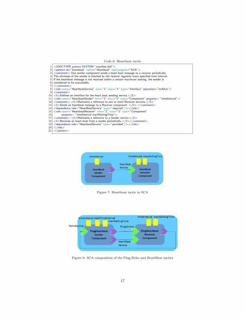
Fig. 7 shows the Heartbeat design pattern in SCA as another example of
15

Figure 6: Ping/Echo tactic in SCA
tactic for availability. It detects a fault by listening to heartbeat messagesfrom monitored components periodically. A sender sends a heartbeat mes-sage to a receiver (operation imAlive) every specified time interval (propertytimeInterval). The receiver updates the current time when it receives theheartbeat message. The aliveness of the sender is checked by the receiver reg-ularly every specified time interval (property timeInterval) by comparing thelatency time between the current time and the last time of a heartbeat messageis received from the server. If the heartbeat message is not received within a cer-tain time (property maxWaitingTime) the sender is considered to be unavailable.Code 6 shows the XML file defining the Heartbeat tactic.
The Ping/Echo tactic and the Heartbeat tactics can be combined to makemore efficient and bidirectional the fault detection mechanism. The result ofthis tactic composition is shown in Fig. 8 using SCA. Technically it has beenobtained by applying the Heartbeat tactic to the SCA asssembly of the Ping-Echo tactic. Property re-naming is necessary to avoid ambiguities. For example,property timeInterval of the role HeartBeatSender of the Heartbeat tactic isrenamed in beatTimeInterval. The result of this pattern composition can besaved and reused as new compound design pattern.
4. SCA-PatternBox framework
SCA is supported by an Eclipse-based design tool and runtime platforms forthe development of service-based applications. Based on the ideas of model-based development, the proposed framework SCA-PatternBox is Eclipse-basedand complements the SCA design environment by the use of a collection ofmodels to specify and configure architectural design patterns and the auto-mated application of them in the development of SCA models of service-orientedapplications. SCA aims to encompass a wide range of target implementationtechnologies for SCA service components and for the access methods which areused to connect them. In our work, we focused on the SCA-Java implementationtype and on the SCA-ASM formal specification type.
In the following, we provide an overview of the SCA-PatternBox framework,a general methodology for application designers to develop service-oriented com-ponent architectures using SCA-PatternBox and design patterns, and a descrip-tion of the supported formal analysis techniques.
16
Code 6: Heartbeat tactic
1 <!DOCTYPE pattern SYSTEM ”manifest.dtd”>2 <pattern id=”heartbeat” name=”Heartbeat” topCategorie=”SCA”>3 <comment> One sender component sends a heart beat message to a receiver periodically.4 The aliveness of the sender is checked by the receiver regularly every specified time interval.5 If the heartbeat message is not received within a certain maximum waiting, the sender is6 considered to be unavailable.7 </comment>8 <role name=”HeartbeatService” min=”1” max=”1” type=”Interface” operation=”imAlive”>9 <comment>
10 <li>Defines an interface for the heart beat sending service.</li>11 <role name=”HeartbeatSender” min=”1” max=”1” type=”Component” property= ”timeInterval”>12 <comment> <li>Maintains a reference to one or more Receiver services.</li>13 <li>Sends an heartbeat message to a Receiver component. </li> </comment>14 <dependence role=”HeartBeatService” type=”required”/></role>15 <role name=”HeartbeatReceiver” min=”1” max=”1” type=”Component”16 property= ”timeInterval maxWaitingTime”>17 <comment> <li>Maintains a reference to a Sender service.</li>18 <li>Receives an heart beat from a sender periodically.</li></comment>19 <dependence role=”HeartbeatService” type=”provided”/></role>20 </role>21 </pattern>
Figure 7: Heartbeat tactic in SCA
Figure 8: SCA composition of the Ping/Echo and HeartBeat tactics
17

Figure 9: SCA-PatternBox architecture
4.1. Framework architecture
Fig. 9 shows the SCA-PatternBox architecture using a free-style notation,while Fig. 10 shows a screenshot of the Eclipse view of SCA-PatternBox. SCA-PatternBox includes a design pattern editor, code generators for producing SCA-Java code and SCA-ASM specifications, and a pattern composer. It also exploitsan external formal analysis environment for SCA-ASM specifications.
Pattern editor. The pattern editor adopts a template-based approach that al-lows you to insert new pattern definitions (file Mypattern.xml in Fig. 9, andappropriate templates (file Mytemplate.xml in Fig. 9) for the generation ofSCA-Java code and of SCA-ASM formal specifications. A design pattern isdefined in an XML file within a predefined directory pattern.mf and must beconforming to the DTD manifest.dtd within the same directory.
Code generator. There exists an XML-based template files within the prede-fined directory template.java and within template.asm of SCA-PatternBoxfor each design pattern to support the generation of the corresponding SCA-Javacode and SCA-ASM specification, respectively. For the SCA-Java code genera-tion, we extended the existing PatternBox XML grammar templates.dtd to al-low the use of Java annotations for SCA into the code templates, and the sourcecode of PatternBox (CodeTemplateXmlHandler.java and MemberCodeGenera-
tor.java) to generate Java code from the pattern code templates with the ap-propriate SCA annotations. The code generator makes intensive use of Eclipse’sJava development tooling (JDT) and the Plug-in Development Environment(PDE). It creates Java classes and interfaces according to the code templatesand generates also an SCA XML assembly file corresponding to it. Fragmentsof SCA assembly files and the associated Java skeleton code can be thereforeproduced from scratch from a pattern definition.
18

Pattern composer. The composer supports the composition and application ofdesign patterns on existing SCA assemblies (and on the corresponding Javaor ASM implementation). Currently, the composition is carried out in an in-teractive manner, indeed the designer has to specify the names of the elements(components or interfaces) from the SCA assembly that play specific roles of thedesign pattern. The composition strategy is incremental, i.e., the application ofdesign patterns to an existing SCA assembly is made through a sequential chainof adaptation actions of the SCA assembly and of the associated componentsimplementation according to the pattern definitions.
Formal specification and analysis environment. The formal analysis environ-ment allows for an early and formal validation of the design of a service-orientedapplication. It consists of the Eclipse-based SCA-ASM design and executionframework for the simulation of SCA-ASM components within an SCA assem-bly (exploiting the SCA Tuscany runtime platform), and of the ASM analysistoolset ASMETA [11, 12]. An SCA-ASM specification of a service-oriented com-ponent (or of a component assembly), possibly not yet implemented in code oravailable as off-the-shelf, can be: (i) simulated and possibly formally verified(by model checking techniques) offline, i.e., in isolation from the other compo-nents, by the use of the ASM toolset ASMETA; (ii) configured in place withinthe SCA Tuscany runtime platform as abstract implementation (or specifica-tion) of a “mock” component and then executed with the other componentsimplementations according to the chosen SCA assembly.
This toolkit allows to study the behavior of some “critical” components in aformal way before the final transformation into a specific implementation code.The same consideration also apply to component assemblies representing designpatterns that can be therefore specified formally in SCA-ASM as abstract andpartially complete specifications. Moreover, once these patterns are instantiatedinto the current SCA design and their specification in SCA-ASM is completed,the structural and behavioral conformance of the component assemblies to de-sign patterns can be (potentially) checked formally.
4.2. Framework methodology
A general and agile development of an SCA service-oriented component ar-chitecture (or SCA assembly) with SCA-PatternBox can be organized in thefollowing steps (see also Figure 11).
Step 1: Sketch an outline of the application’s architecture. Define an SCAassembly of the service-oriented application with the SCA Composite Designerby determining the ground services and components required according to themain requirements and use cases from the user perspective.
Step 2: Refine the architecture. Identify the main ways in which the com-ponents will interact and the interfaces between them. Decide how each pieceof data and functionality will be distributed among the various components.Choose among the various service-oriented design patterns. Instantiate andcompose them within the SCA assembly.
19

Figure 10: A screenshot of the SCA-PatternBox framework
Step 3: Finalize the interfaces. Consider each use case and adjust the archi-tecture to make it realizable trying to finalize the interface of each component.Refine components properties in the SCA assembly.
Step 4: Map design to implementation. Finalize the architecture as you de-fine the final implementation classes for components and interaction protocolsaccording to the (possibly many and different) target implementation technolo-gies. Determine if you can re-use existing components implementations beforeimplementing them from scratch. You may implement, for example, some SCAcomponents in SCA-Java and adopt Java-based standard communication bind-ings – such the Java API for RESTful Web Services (JAX-RS) or the JavaMessage Service (JMS) – for specifying how SCA services and references enablea component to communicate with other components/applications.
Step 4′: Map design to formal specification. Optionally, you can specifyformally the behavior of some “critical” components using the SCA-ASM im-plementation type.
Step 5: Formal validation. Optionally, once specified formally the behaviorof some components or of a component assembly in SCA-ASM (Step 4′), youmay validate such components or assembly separately (in an offline manner)using the ASM analysis toolset ASMETA.
Step 6: Overall design validation. Execute and validate the overall SCAassembly of the application within an SCA runtime platform (like Tuscany).
More sophisticated development processes can be adopted as well. SCA-PatternBox has been used, for example, to support a design exploration process[15] involving more automation and combining meta-heuristic search techniqueswith design patterns to produce and evaluate different design alternatives.
20

Figure 11: Model development steps with SCA-PatternBox
4.3. Formal analysis techniques
We here describe the SCA-ASM model analysis activities we can performoffline for validating and verifying the functional behavior of design patterns,and getting early feedback (already at system design time) of their functionalcorrectness before applying them in concrete systems implementations.
Validation is the process of investigating a model with respect to the userperceptions in order to ensure that the model really reflects the user needs andstatements about the application. On the SCA-ASM models of design patternsand their concrete instantiations, formal validation can be carried out in termsof model simulation and construction of execution scenarios – scenario-basedvalidation – through the execution platform for SCA-ASM [7] and the ASMsimulator AsmetaS [14] and validator AsmetaV [13] provided by the ASMETAframework [11, 12]. Fig. 12 shows the validation process: the user can directlysimulate an ASM-based specification in an interactive way or write a scenariothat automatizes the simulation and the checking of the produced output. Earlyvalidation by model simulation is a great means for evaluating architectural
21

Figure 12: Validation in the ASMETA framework
choices and alternative designs with limited implementation effort, and usually,though not in an exhaustive manner, it permits to detect faults in the specifi-cation with limited effort w.r.t. more sophisticated analysis techniques such asproperty verification through model checking.
Model simulation and Scenario-based validation. AsmetaS permits to performeither interactive simulation, where required inputs are provided interactivelyby the user during simulation, and random simulation, where inputs valuesare chosen randomly by the simulator itself. The simulator, at each step, per-forms consistent updates checking to check that all the updates are consistent:in an ASM, two updates are inconsistent if they update the same location totwo different values at the same time [8]. In preliminary versions of our pat-terns specifications, by simulation we found some consistency violations dueto a wrong order scheduling of the send-receive operations of the participantsagents. Moreover, the AsmetaS simulator also permits to check if some invari-ants are satisfied during simulation. Obviously, by simulation we can verifyonly the states covered by the executed runs, whereas model checking (see nextparagraph) gives the assurance that the invariants hold in each model state.
A more advanced way to simulate and inspect ASMs is by specifying ascenario representing a description of the actions of an external actor and thecorresponding reactions of the system. There are two kinds of external actors:• a user interacts with the system in a black box manner, by setting the
values of the external environment (e.g., asking for a particular service),waiting for a step of the machine as reaction to his/her request, and check-ing the output values;
• an observer, instead, can also inspect the internal state of the system (i.e.,values of machine functions) and check the validity of possible invariantsof a certain scenario.
Scenarios are described in an algorithmic way using the textual language Avalla [13].A scenario is as interaction sequence consisting of actions of the external actor(user or observer) and activities of the machine as reaction to the actor ac-tions. The Avalla language provides constructs to set the environment (i.e.,the values of input/shared functions), to check the machine state, to ask forthe execution of certain transition rules, and to force the machine itself to makeone step (or a sequence of steps by step until).
22

1 scenario request−response2 load mainRequestResponse.asm3 ...4 //for the startup of the client and server agents5 set status(c) := READY;6 set fRequestResponse(c) := s;7 set items(c):= ...;8 set ...9 exec r wsendreceive[fRequestResponse(c),”r request(Agent,D)”,items(c),result(c)];
10 step11 check isDef(response(fRequestResponse(c))) and isDef(result(c));12 ...
Code 7: Request-response validation scenario in Avalla
The tool AsmetaV reads scenarios written in Avalla and executes them usingthe simulator AsmetaS; during simulation, AsmetaV captures any check violationand, if none occurs, it finishes with a PASS verdict (see Fig. 12).
As an example, the excerpt of the scenario reported in Code 7 describesthe interactions among the client c and server agents s in the pattern request-response from the client side. Appropriate assertions control that the resultmessage is sent. This scenario has to be used as a template and therefore it hasthen to be instantiated according to the real services and components involvedin the pattern instance. An example of its instantiation will be given for thecase studies presented in Sect. 5.
Model verification. Model checking is an automated formal verification tech-nique based on state exploration of the system to be checked. AsmetaSMV [5]is a tool of the ASMETA framework that translates ASM specifications intomodels of the NuSMV model checker. It allows the verification of ComputationTree Logic (CTL) and Linear Temporal Logic (LTL) formulae expressing desiredbehavioral properties of the system under verification.
Behavioral properties related to interactions among the participants (agents)can be obtained from a pattern definition and then expressed and configuredin terms of CTL formulae within the SCA-ASM model itself of the patterninstance. This last is then validated against the behavioral properties by usingthe AsmetaSMV model checker. Thereafter the state space of the SCA-ASMmodel to be checked is searched by the model checker to verify or falsify (bygenerating counterexamples) the CTL properties.
For our purposes, CTL can be used to express a temporal ordering betweensend and receive messages in a sequence of interactions among agents or alsogeneral properties such as reactivity and liveness. For example, the followingCTL property can be checked to validate the reactivity of the behavior of aninstance of the Request-Response micro-pattern:
ag(isDef(nextRequest(server)) implies af(isDef(result(client(server)))))
It specifies that whenever there is a request, eventually the server (agent serverof type RequestResponseService) will reply producing a result for the client.
23

The formula has then to be instantiated according to the real services of thecomponents involved in the pattern instance.
Liveness properties (informally, liveliness means that some actions will beexecuted infinitely) can be expressed and verified by giving explicit fairnessrequirements. For example, for the Ping-echo tactic, used to test the reachabilityof a host, the following property can be checked for a timed confirmed sender.Property: A ping message is always followed by an echo confirmation messageor timeout:
ag( ping(sender,receiver) implies af( (maxWaitingTime(sender) and not(echo(receiver,sender)))or (not(maxWaitingTime(sender)) and echo(receiver,sender))) )
where we assumed the following atomic propositions: ping(sender,receiver) ≡ aping request has been sent from the sender to the receiver, echo(receiver,sender)≡ an echo request has been sent back from the receiver to the sender, andmaxWaitingTime(sender) ≡ the ping request is not answered with the echoreply within the given time.
Invariants, i.e. properties that must hold in all the states, can be alsochecked. For example, for a Request-Response micro-pattern we can verify that,after making the request in a synchronous manner by a send-receive action, theclient effectively remains blocked until it receives back the result:
ag( isDef(awaitingRespMsg(client)) implies status(client) = BLOCKED)
where client is the client component’s agent and the controlled function await-ingRespMsg, that is set within the predefined rule send-receive [7], stores themessage for which the client agent is waiting to receive the corresponding re-sponse message. Invariants are useful, for example, for guaranteeing certainsafety properties (informally, that nothing will go wrong with the system) byverifying that invariants’ formulae are effectively true at all states of the system.
Currently, the derivation of CTL formulae from a pattern definition is car-ried out by hand. We postpone as future work the automatic generation ofCTL formulae and their configuration with information from concrete patterninstances. Moreover, verification of properties on large SCA-ASM models ispossible, but it would require the use of some model slicing and model abstrac-tion techniques in order to avoid the well-known problem of state explosion ofthe model checking, and make the verification feasible.
5. Illustrative case studies and lessons learned
This section presents two case studies as illustrative examples of the proposedframework. In the first example, we designed and validated a service-orientedarchitecture model for the Order system case study [24]. As second example, weconsidered the Stock Trading system originally presented in [16]. Finally, thesection reports our lessons learned as gained by our experience in developingthese case studies.
24

Figure 13: SCA assembly of the Order System
5.1. The Order System
The Order system is essentially an exercise of requirements capture, noto-riously a difficult and error prone activity that requires a formalization task.To this purpose, we show how the SCA-ASM method allows one to captureinformal functional requirements of a system architecture, including both thestructural and behavioral aspects of services.
The main service of the system is that of invoicing orders. Every order refersto a product for a certain quantity (greater than zero). The same product can bereferenced by several different orders. Every product is in the stock in differentquantity. Invoicing requires to check if the order can be satisfied, i.e. if theordered quantity of products is less than or equal to the quantity in stock. Ifso, the stock is updated and the order state changes from the state pending tothe state invoiced. If the order cannot be satisfied, it is left pending.
Two additional services offered by the system are: cancel orders and addnew quantities of products in the stock. A customer can only cancel his or herpersonal orders. The order is cancelled if it is still pending. When the order isalready invoiced, the conflict must be resolved manually by the user. For thethird functionality of adding a quantity of product in the stock, the productmust be already registered in the system because the system does not considerentries of unreferenced products. So for each product entry, the supplier mustspecify the product provided and its quantity.
5.1.1. Step 1 – Sketch an outline of the application’s architecture
According to Step 1 of the design methodology presented in Sect. 4.2, wemodeled the initial SCA architecture of the system based (see Fig. 13) on themain service of invoicing orders, and the additional services for order cancella-tion and supply new products quantity. Essentially, we consider the followingapplication scenarios.
25

Order management (order entry/cancellation). For an order entry scenario, theuser requirements specify that an order is made by sending (the service opera-tion sendOrder(ref, qty, customerID)) a reference to the desired product, aquantity, and a customer identifier to the system. So the methodology leads usto define a service-oriented component namely OrderManagement, which takesinto account this entry and is in charge of saving internal orders. For an ordercancellation, we assume that a customer must identify the order he wants tocancel and invokes the service operation cancelOrder(orderID, customerID)
also offered by the component OrderManagement. This last checks that the cus-tomer can cancel the order (a customer can cancel only one of his or her orders,not the order of another customer) and if it is the case, cancels the order.
Stock Management. We assume that all products are already referenced inthe system. So, when a supplier sends a new quantity of product to theStockManagement component (by invoking the service operation productEntry
(productID, qty)), the product quantity is updated.
Invoicing Management (order invoicing). The OrderManagement componentonly registers in the database that there are new orders to invoice (i.e., ordersinitially pending), while the component InvoicingManagement is in charge ofeffectively invoicing orders. This last component does not expone any puplicservice. It executes the order invoicing functionality in background. Essentially,it selects a set of orders which are invoicable, i.e. they are pending and refer toa product in the stock in enough quantity, it simultaneously changes the stateof each order in this set from pending to invoiced, and updates the stock bysubtracting the total product quantity in orders to invoice. The system keepsto invoice orders as long as there are orders which can be invoiced. The systemguarantees that the state of an order is always defined and the stock quantityis always greater or equal to zero.
5.1.2. Steps 2 and 3 – Refine the application’s architecture and finalize the in-terfaces
The second step of the methodology suggests to refine the architecture byintroducing new components and using design patterns.
First, we decided to organize the overall system architecture according to thethree-layer architectural pattern5 by introducing the components GUI, Application,and Data. The component Data represents the data layer of a classical three-layer-architecture so it hides details of the database and provides data accessto the application layer represented by the component Application. Thecomponent Application contains the application logic. It uses the servicesQueryService and PersistenceService defined by the component Data inorder to send queries or changes to the database, and provides the interfaceStoreService to deliver results of database queries to the component GUI. Thislast acts like an interface for the user and the Application component.
5The templates definition and SCA assembly of such patterns are available online at [34].
26

Figure 14: SCA Order system refined (Step 2 - GUIApplicationData design pattern)
We identify the OrderSystem composite component introduced in the pre-vious step as the component Application. So according to the three-layerarchitectural pattern, we have to refine the OrderSystem component to allowthe interaction with two other external components: the OrdersDBComponent
(the Data component) and the GUIComponent (the GUI). These last are left inabstract. The result of such refinement is shown in Fig. 14.
According to the user requirements, the InvoicingManagment componentcan adopt different selection strategies of orders to invoice: single-order, all-or-none, max-orders, and default. Single-order strategy means that per step atmost one order is invoiced, with an unspecified schedule (thus also not takinginto account any arrival time of orders). In case all orders for one productare simultaneously invoiced or none if the stock cannot satisfy the request, aall-or-none strategy can be expressed. To further maximize a product quantityinvoiced at the time, a new strategy (strategy max-orders) consists in choosinga maximal invoicable subset of simultaneously invoiced pending orders for thesame product. If the user requests a selection strategy which is not drivenby a first choice of a product, another possible strategy consists in choosinga set of pending orders, with enough referenced products in the stock, to besimultaneously invoiced. This last strategy matches the intended behavior ofthe system better than the previous ones, so it is the default strategy. Forsupporting one of this mode of operation, we added to the InvocingManagementcomponent the property OrderPolicy (see Fig. 14) whose value range in theset {single-order, all-or-none, max-orders, or default}. By default, this propertyis initialized to the value default.
As further refinement, we applied the router pattern6 to enable different in-voicing strategies as implemented by different business components: SingleOrder-BComponent, AllOrNoneBComponent, MaxOrdersBComponent, and DefaultB-
Component (see Fig. 15). The router component, i.e. the InvoicingManagment
component, is responsible for sending the pending orders to a certain businesscomponent for invoicing them according to a specific strategy (the routing cri-
6The templates definition and SCA assembly of such patterns are available online at [34]
27

Figure 15: SCA Order system refined (Step 2 - Router design pattern)
Code 8: ASM module of the InvoiceOrdersService interface
1 module InvoiceOrdersService2 import STDL/StandardLibrary3 import Order //Interface of the Order data type4 signature:5 // the domain defines the type of the provider component’s agent6 domain InvoiceOrdersService subsetof Agent7 out invoiceOrders: Prod(Agent, Powerset(Order)) −> Powerset(Order)
teria) as reflected by the current value of the property OrderPolicy.The third step of the methodology is to finalize the interfaces and properties
of each component in the SCA assembly. So we added the service operations tothe interfaces and properties types.
5.1.3. Steps 4′ and 5 – Map design to formal specification and formal validation
Being a design from scratch, before implementing components in Java wepreferred specifying the behavior of the business components for invoicing or-ders formally using SCA-ASM. The complete SCA-ASM implementation of suchcomponents is also available at [34].
The default invoice strategy (the InvoiceOrdersService service) is pro-vided by the business component DefaultBComponent. The ASM definitionfor the interface InvoiceOrdersService is reported in Code 8. It is an ASMmodule containing only declarations of a business agent type (the subdomainInvoiceOrdersService of the predefined ASM Agent domain) and of a busi-ness function used as temporary location to store service computation results(i.e., the orders to invoice) to return back to the service caller.
The behavior of the DefaultBComponent is formalized in SCA-ASM as re-ported in Code 9. The service rule invoiceOrders uses a predicate invoicable
28

Code 9: The behavior of the DefaultBComponent
1 asm DefaultBComponent2 import STDL/StandardLibrary3 import STDL/CommonBehavior4 import InvoiceOrdersService5 signature:6 //@Backref7 shared client: Agent −> Agent8 // orders to invoice9 controlled orders: Agent −> Powerset(Order)
10 definitions:1112 rule r DeleteStock($p in Product ,$q in Natural) = stockQuantity($p):= stockQuantity($p) − $q1314 //@Service Choose subset of orders15 rule r invoiceOrders($a in Agent, $orders in Powerset(Order)) =16 choose $orderSet in Powerset($orders) with invoicable($orderSet) do17 par18 forall $order in $orderSet with true do orderState($order) := INVOICED19 forall $product in referencedProducts($orderSet) with true do20 r DeleteStock[$product, totalQuantity($orderSet,$product)]21 invoiceOrders(self,orders(self)) := $orderSet //setting of the out business function22 endpar2324 rule r DefaultBComponent =25 if nextRequest(self)=”r invoiceOrders(Agent, Powerset(Order))” then26 seq27 r wreceive[client(self),”r invoiceOrders(Agent, Powerset(Order))”,orders(self)]28 if (isDef(orders(self))) then r invoiceOrders[self,orders(self)] endif29 r wreply[client(self),”r invoiceOrders(Agent, Powerset(Order))”,invoiceOrders(self,orders(self))]30 endseq31 endif3233 rule r init($a in InvoiceOrdersService) = status($a):=READY
that is true on a set of pending orders with enough quantity of requested prod-ucts in the stack, and a function refProducts which yields the set of all productsreferenced in a set of orders. Note that the non-deterministic selection of theorders to invoice could be performed by a input function which would formalizethe user selection of a set of orders or the results of a particular scheduling.
A single-order strategy is realized by the service invoiceSingleOrder asprovided by the SingleOrderBComponent. This service’s behavior is formalizedin SCA-ASM as reported in Code 10. Per step at most one order is invoiced,with an unspecified schedule (by the choose rule contructor).
The InvoiceAllOrNone service of the AllOrNoneBComponent for the all-or-none strategy can be specified in SCA-ASM as reported in code 11. The servicerule makes use of a function pendingOrders yielding the set of pending ordersfor a certain product, and of a (static) function totalQuantity returning thetotal quantity of a set of orders.
Finally, the service InvoiceMaxOrders can be formalized in SCA-ASM asshown in code 12. For this rule we need to define a static function maxQuantitySub-
sets which, given a set of set of orders, returns the set of all the sets having amaximum quantity.
The Order system case study was essentially a requirements formalization
29

Code 10: The behavior of the invoiceSingleOrder service
1 //@Service Invoice an order at a time.2 rule r invoiceSingleOrder($a in Agent, $orders in Powerset(Order)) =3 choose $order in orders with orderState($order) = PENDING do4 if(orderQuantity($order) <= stockQuantity(referencedProduct($order))) then5 par6 orderState($order) := INVOICED7 r DeleteStock[referencedProduct($order),orderQuantity($order)]8 invoiceSingleOrder(self,orders(self)) := $order //setting of the out business function9 endpar
10 endif
Code 11: The behavior of the InvoiceAllOrNone service
1 //@Service All orders for one product are simultaneously invoiced or none.2 rule r invoiceAllOrNone($a in Agent, $product in Product) =3 let ( $pending = pendingOrders($product) ) in4 let ( $total = totalQuantity($pending) ) in5 seq6 if $total > 0 and $total <= stockQuantity($product) then7 par8 forall $order in $pending do orderState($order) := INVOICED9 r DeleteStock[$product, $total]
10 endpar11 endif12 invoiceAllOrNone(self,product(self)) := $pending //setting of the out business function13 endseq14 endlet15 endlet
Code 12: The behavior of the InvoiceMaxOrders service
1 //@Service Invoice maximum orders for one product.2 rule r InvoiceMaxOrders($a in Agent, $product in Product) =3 let ($pending = pendingOrders($product)) in4 let ($invoicablePending = {$o in $pending | totalQuantity($o) <= stockQuantity($product) : $o}) in5 choose $orderSet in maxQuantitySubsets($invoicablePending) do6 par7 forall $order in $orderSet do orderState($order) := INVOICED8 r DeleteStock[$product, totalQuantity($orderSet)]9 invoiceMaxOrders(self,product(self)) := $orderSet //setting of the out business function
10 endpar11 endlet12 endlet
30

1 scenario DefaultInvoicingManagement2 load main.asm3 ...4 //for the startup of the client and server agents5 set status(c) := READY;6 set fRequestResponse(c) := s;7 set orders(c):= ...;8 set ...9 exec r wsendreceive[fRequestResponse(c),”r invoiceOrders(Agent,Powerset(Order))”,orders(c),result(c)];
10 step11 check isDef(invoiceOrders(fRequestResponse(c),orders(c))) and isDef(result(c));
Code 13: Validation scenario in Avalla for the InvoicingManagementComponent – default strat-egy
task and we have shown how the SCA-ASM method allowed us to captureinformal functional requirements of systems services by constructing a consis-tent and unambiguous, simple and concise, abstract and complete models ofservice-oriented components, including behavioral aspects of services. Thesemodels can be understood and checked (for correctness and completeness) byboth domain experts and system architects/designers. For example, Code 13reports a simulation scenario in Avalla (instantiated from the one reported inCode 7) for checking the orders invoicing. It checks the interactions among theOrderDeliveryComponent (the client c) and the default business component(the server agent s) in the pattern request-response from the client side. Ap-propriate assertions control that the result message (the set of orders to invoiceas chosen by the default strategy) is sent.
Through the requirements capture we have introduced several assumptionsto fill missing information. We introduced some assumptions directly in thespecification by means of invariants and used the AsmetaS simulator to checkthem during simulation. For example, the assumption that the quantity in everyorder must be greater than 0 is formalized as:
invariant over orderQuantity:forall $o in Order with orderQuantity($o) > 0
We have also stated the following desired properties which express state invari-ants and correctness conditions. The first one states that the stock quantity isalways greater than 0.
invariant over stockQuantity:forall $p in Product with stockQuantity($p)>=0
The second property is that the state of every order is either pending or invoiced,but never undefined.
invariant over orderState:forall $o in Order with orderState($o) != undef
For other more complex properties, which are not state invariants but theyrefer to execution paths, the model checker can be used, although assumptionsabout the finiteness of the domains are necessary and uninterpreted domains arenot allowed. For example, one may want to express that an order o is eventually
31

invoiced if it refers to a product available in the stock in enough quantity. InCTL, this can be expressed as:
AF( AG( orderState(o) = INVOICED ororderQuantity(o) > stockQuantity(referencedProduct(o)))
5.1.4. Steps 5 and 6 – Mapping design to implementation and overall designvalidation
In a further iteration of the methodology, we implemented in Java (Step 4)the components OrderManagement, InvoicingManagement, and StockManagement
as mock components, and then execute and validate the overall SCA assemblyof the application within the SCA runtime platform (Step 6). We did noteffectively implemented all the system in Java since, being an example of re-quirements elicitation, our main goal was to develop a ground model showinghow the SCA-ASM formal method allows one to capture informal behavioralrequirements of components’ services. So, for validation we used orders collec-tions and customers identifiers with fixed values to avoid at this design phasethe implementation of a real database component.
5.2. The Stock Trading System
The goal of such a case study is to embody non-functional requirements(NFRs) using architectural tactics. We chose such a case study as major evalua-tion of the SCA-PatternBox language and tool and as a comparative benchmarkbecause our work is on the spirit of the approach in [16] for design pattern speci-fication and application (see related work in Sect. 6.1), but instead of extendingUML diagrams like the approach in [16] does, we preferred just to specify whatis really needed to express a design pattern for facilitating pattern instantiationand code generation.
Our case study was adopted in the adaptation exploration process presentedin [15]. It consists of an optimization process with respect to different archi-tectural configurations of the system for multiple adaptation scenarios (e.g., auser claims a new level of reliability and response time, or the monitor raisesthe violation of the minimum level of required availability).
Figure 16 shows the initial SCA assembly of the STS obtained by carryingout Step 1 of the design methodology presented in Sect. 4.2. Briefly, an STSuser, through the OrderWebComponent interacting with the OrderDelivery-
Component, can check the current price of stocks, placing buy or sell ordersand reviewing traded stock volume. Moreover, he/she can know stock quoteinformation through the StockQuoteComponent. STS interacts also with anexternal Stock Exchange system.
By executing steps 2 and 3 of the methodology, architectural tactics areselected, composed and instantiated based on a given set of NFRs to refine theinitial architecture of the application into one that meets the desired NFRs.We here show, in particular, how availability and performance tactics can beused to embody NFRs into the SCA architecture of the STS application. Letus assume the following NFRs (as taken from [16]):
32

Figure 16: SCA assembly of the Stock Trading System
– NFR1. The STS should be available during the trading time (7:30 AM – 6:00PM) from Monday through Friday. If there is no response from the system for30 s, the STS should notify the administrator.– NFR2. The system should be able to process 300 transactions per second,400,000 transactions per day. A client may place multiple orders of differentkinds (e.g., stocks, options, futures), and the orders should be sent to the systemwithin 1 s in the order they were placed.
We support NFR1 by applying the Fault Detection tactics Ping/Echo andHeartbeat through a monitoring component playing the role of PingHeartbeat-Receiver. NFR2 is supported by combining the tactics FIFO and IntroduceConcurrency. The FIFO tactic allows clients to place each type of orders (e.g.,stocks, options, futures) to a dedicated queue for immediate processing. TheIntroduce Concurrency tactic allows the concurrent dispatching of the samekind of orders thus reducing the blocking time of transactions on I/O. Fig-ure 17 shows the new SCA assembly obtained by composing these tactics: theassembly is extended to add the new component Monitoring (for the Fault De-tection tactics) and to refine the existing components OrderWebComponent andOrderDeliveryComponent. These last two components are to be intended assubsystems, indeed they are composite components with a hierarchical designnot further reported here. In particular, the OrderDeliveryComponent is re-fined for adding a queue sub-component for the FIFO tactic, a sub-componentfor the functionality of a PingHeartbeatReceiver role and for the concurrentconsuming of different kinds of orders placed into the queue sub-component.Similarly, the OrderWebComponent is refined by adding a sub-component for con-currently producing orders to place into the queue of OrderDeliveryComponent.Of course, this refinement implies a change of the components shape (i.e., in therequired/provided interfaces) and of their behavior.
Some components were implemented in SCA-ASM (Step 4′). As an example,Code 14 shows a fragment of an SCA-ASM specification of the OrderDelivery-Component. The main service of this component (the rule r place annotatedwith @service) is to place buy or sell orders when requested (see the blocking
33

Figure 17: SCA assembly of the STS after applying tactics for NFR1 and NFR2
Code 14: The behavior of the OrderDeliveryComponent
1 module OrderDeliveryComponent2 ...3 @Service4 rule r place($client in Agent,$o in Order)= ... //to place buy or sell orders5 ...6 rule r OrderDeliveryComponent=7 seq8 r wreceive(client(self),”place”,order(self))9 r place(client(self),order(self))
10 r wreply(client(self),”place”,place(self,order(self)))11 endseq12 ...
receive action and the reply action preceding and following, respectively, the ser-vice invocation within the component’s main rule r OrderDeliveryComponent).The ASM definition for the provided and required interfaces of the OrderDeli-
veryComponent are reported in Code 15. They are ASM modules containingonly declarations of business agent types (the subdomains OrderDelivery andStockExchange of the predefined ASM Agent domain) and of business func-tions (parameterized ASM out functions) used as temporary locations to storeservice computation results.
Code 16 reports a simplified fragment of a simulation scenario (instantiatedfrom the one reported in Code 7) for checking the order placement executed bythe OrderDeliveryComponent.
The SCA-ASM specification of some components behavior were further re-fined to reflect at behavioral level the Introduce Concurrency tactic. The behav-ior, for example, of the OrderDeliveryComponent was further refined in ASMas shown in the fragment reported in Code 17: the consuming and sending of
34

Code 15: ASM modules of the OrderDeliveryComponent interfaces
1 module OrderDeliveryService2 import ... //Other module imports3 signature:4 // the domain defines the type of the provider component’s agent5 domain OrderDelivery subsetof Agent6 // business function value7 out place: Prod(Agent,Order) −> Order89 //@Remotable
10 module StockExchangeService11 import ... //Other module imports12 signature:13 domain StockExchange subsetof Agent14 out sendOrder: Prod(Agent,Order) −> Rule
1 scenario OrderPlacement2 load main.asm3 ...4 //for the startup of the client and server agents5 set status(c) := READY;6 set fRequestResponse(c) := s;7 set order(c):= ...;8 set ...9 exec r wsendreceive[fRequestResponse(c),”r place(Agent,Order)”,order(c),result(c)];
10 step11 check isDef(place(fRequestResponse(c),order(c))) and isDef(result(c));
Code 16: Validation scenario in Avalla for OrderDeliveryComponent
different kind of orders (stock, option, or future) are executed concurrently bythe par rule. The availability of such pattern specified in abstract terms byASM allowed us to formally validate early in the design the benefits providedby such a tactic (Steps 5 and 6).
5.3. Lessons Learned
We found the modeling approach to the definition of design patterns andtheir instantiation in SCAPatternBox particularly useful. First, exploiting theexisting PatternBox tool for Java allowed us to develop a large and sophisticatedtool for SCA in a very short period of time. The ability to work with designpatterns in conjunction with SCA and supporting implementation types wasthe major benefit. We found it very sympathetic to the implementation of theskeleton code of the application that is obtained automatically from an SCAassembly model and through pattern instantiation.
SCA-ASM allows modeling both structure and behavior of service compo-nents in a unique framework integrating architectural and behavioral views.Moreover, SCA-ASM gives us an avenue for the formal validation of the patternand of the application model to which the pattern is applied. ASM rigorous-ness, expressiveness, and executability allowed us to reason and validate someservices interaction patterns in a formal way but without mathematical overkill.Formal validation can be carried out on SCA-ASM specification fragments re-
35

Code 17: The refined behavior of the OrderDeliveryComponent
1 module OrderDeliveryComponent2 ...3 rule r OrderDeliveryComponent=4 ... seq5 par //Queue consuming6 r wsendreceive[queue(self),”dequeue”,(”Stock”,stockorder(self))]7 r wsendreceive[queue(self),”dequeue”,(”Option”,optionorder(self))]8 r wsendreceive[queue(self),”dequeue”,(”Future”,futureorder(self))]9 endpar
10 par //Order sending to the Stock Exchange system11 r wsend(stockExchange(self),”sendOrder”,(self,stockorder(self)))12 r wsend(stockExchange(self),”sendOrder”,(self,optionorder(self)))13 r wsend(stockExchange(self),”sendOrder”,(self,futureorder(self)))14 endpar15 endseq ...
sulting from the instantiation from scratch of single design patterns or from thecomposition of two or more patterns, or on an entire SCA-ASM specificationresulting from the application of one or more design patterns on an existingSCA assembly (partially) implemented in SCA-ASM.
During the development of the case studies, for example, we implementedsome components in SCA-ASM in order to have an ASM (abstract) formal speci-fication of their behavior. We then validated the corresponding SCA-ASM spec-ification fragments before and after the application of some formally-validateddesign patterns, (such as the application of the three-layer and Router patternsto the SCA assembly of the Order system, and of the the Ping-echo and Heart-beat tactics to the STS SCA assembly). We experienced that ASM is a goodformalism for prototyping and simulation purposes. We have carried out modelvalidation through the SCA-ASM simulation environment. Model validation isa model analysis activity to be executed from the earlier stages of the modeldevelopment before other more demanding but more sophisticated and complexanalysis techniques such as formal verification by model checking. Formal high-level ASM specifications of SCA components can be assembled together withother SCA components implemented in a different technology (e.g., in Java)and the resulting heterogeneous SCA assembly can be managed and executedwithin the SCA Tuscany runtime platform as. So SCA components can be earlyvalidated at high level of formalization, without caring about implementationdetails.
During the formalization task of the business components in the Order sys-tem case study, we discovered how requirements are often incomplete and as-sumptions must be stated in order to complete the specification. To this pur-pose we noted how the SCA architecture (including design patterns) and theSCA-ASM behavioral specification of a service are easy to adapt when differentinterpretations of same requirements are possible (for example, to support dif-ferent selection strategies of orders to invoice), and how the rigor of the ASMground model allows formal validation and verification of properties. Model val-idation, in general, allowed us to reproduce component configuration scenarios
36

with different pattern instantiations and be confident that the model behavedas expected. We found this early validation is a great means for evaluating ar-chitectural choices and alternative designs with limited implementation effort,but it requires to be skilled in the ASM formal method. On this last point, itis widely recognized that ASMs is a lightweight formal method since ASMs area precise abstract form of pseudo-code, generalizing (the familiar) Finite StateMachines to operate over arbitrary data structures [8].
6. Evaluation of software design pattern languages
Before starting our work, we evaluated the current state of the art. We,in particular, analyzed existing design pattern languages and their supportingtools. This section reports the outcome of such evaluation. In Subsection 6.1we describe the main approaches existing in the literature, while in Subsection6.2 we briefly compare them (including our proposal, i.e., the SCA-PatternBoxpattern language) with respect to some specific criteria.
6.1. Related work
In the literature, there are several notations and tools supporting the processof pattern-based system design and development. Some of these languages arebased on formal mathematical notations (such as [17–21]) or ontology (such as[22]). Other languages are based on the OMG standard UML notation [23,25–27]. Finally, some other languages are based on XML or general purposeprogramming languages [28–30]. Below, we describe some of these approaches.
The Language for Pattern Uniform Specification (LePUS) [17] is based onmathematics and formal logic. It describes only the structure of design patternsand provides a weak basis for integrated tool support. The language eLeLePUS[18] tries rectify the shortcomings of LePUS.
In [19] another formal language is proposed for the behavioral specificationof the GOF design patterns. It is based on the language of temporal orderingspecification (LOTOS). This LOTOS adaptation to patterns did not yield sim-ple and clear specifications. Distributed Co-operation (DisCo) [20] is anotherspecification language for design patterns based on an action system to specifythe behavioral aspects of a pattern.
The Balanced Pattern Specification Language (BPSL) [21] formally specifiesthe structural as well as behavioral aspects of patterns. It was derived from Le-PUS and DisCo, and therefore shares many of the advantages and disadvantagesof the two languages.
Conceptual Ontology Design Pattern (CODeP) [22] is based on the WebOntology Language (OWL) and Resource Description Framework (RDF) forengineering ontology content over the Semantic Web.
Many semi-formal UML-based notations exist. Among the most notableones are the following. ArchInst [31] is a tool developed as a plug-in of theIBM Rational Software Architect (RSA) for UML to support quality-driven de-velopment of software architectures. It allows to configure architectural tactics
37

based on quality requirements and compose the configured tactics to producean initial architecture of the system under development. The tool uses theRole-Based Metamodeling Language (RBML), a UML-based pattern specifica-tion notation presented in a previous work [23], to specify tactics. This UMLextension defines a design pattern in terms of roles and role dependencies. Theconcept of ClassifierRole that RBML uses has been, however, superseded inUML 2.x. In [16, 32], a prototype tool, called RBML Conformance Checker,has been also presented for verifying the conformance of UML models to de-sign patterns. This work demonstrates how instantiated elements conform totheir corresponding metamodel elements. PerOpteryx [25] is an Eclipse-basedoptimization framework to improve component-based software architectures forperformance, reliability, and cost through model-based quality prediction tech-niques and architectural tactics. It is based on the Palladio Component Model(PCM) and a UML-like modeling notation that uses annotated UML models assoftware design models. In [26] a prototype tool named DPTool is presented.It is based on the DPML (Design Pattern Modeling Language) notation for thespecification of design patterns and their instantiation into UML design models.However, the proposed modeling constructs are more complex than other simi-lar UML-based modeling notations. In [27] is presented the problem to preventdefect injection during design-patterns maintenance. A design method calledPattern Instance Changes with UML Profiles (PICUP) has been developed tothis purpose as an improved design method for a corrective UML pattern-baseddesign maintenance and assessment after variations.
These are design pattern languages that are based on general purpose pro-gramming languages. For example, a Prolog-like language called SPINE [28]allows patterns to be defined in terms of constraints on their implementationin Java. It makes addition of patterns and variants easier for those who haveprogrammed in PROLOG before, rather than creating an entirely new syntax.These patterns can then be processed using a proof engine called Hedgehog.Hedgehog reads the SPINE definitions, along with Java source code, and at-tempts to automatically prove whether or not the class correctly realizes thedesign pattern. In [29], AspectJ (aspect-oriented extension to the Java pro-gramming language) is used to provide some improvements to the GoF OOdesign patterns. These improvements allow several advantages like better codelocality, reusability, and composability, but are at code level. No abstract mod-eling notation for pattern specification is supported.
Finally, the Design Pattern Definition Language (DPDL) [30] allows to spec-ify both the structural and behavioral aspects of design patterns. It is a text-based pattern description language purely based on XML, but it is endowed alsowith a graphical representation through an automated transformation of DPDLdescriptions into UML class and sequence diagrams.
6.2. A comparison of design pattern languages
To compare existing design pattern languages, we revised and extended thecomparison framework originally presented in [30]. The criteria adopted forcomparing the languages reflect the main and generally agreed objectives in
38

proposing a language for defining, sharing and applying design patterns intoconcrete system designs. Essentially, a design pattern language should be:
• Easy to understand and use: The language should be easily understand-able by the designers/developers and thus easy to use.
• Unambiguous: The language should have a clear semantics enabling itssharing among design/development teams without any ambiguity.
• Extensible: Because technology is progressing, the language should becapable of being extended.
• Based on existing technology/languages: The language should be basedon existing and common technology/languages so that it gains wider andfaster acceptance.
• Able to support also a graphical notation: A visual representation ofa design pattern and/or a pattern instance provides an intuitive andlightweight overview for the user.
Table 3 below summarizes the results of such a comparison by reporting themain features of the design pattern languages described in Subsection 6.1 andof our proposed language. The main difference with respect to our proposal,is that all the existing approaches that we considered are specific to object-oriented system design. They do not address design patterns related to SOA.Moreover, most of these approaches are not implementation-oriented ; indeed,they provide the needed formality in the pattern specification, for example atUML level, but often at the expense of usability and programmaticity of theapproach because they do not aim at generating the corresponding implemen-tation code. In particular, languages that purely use a mathematical formalismfor modeling design patterns allows to specify the behavioral aspects of a designpattern in a rigorous and unambiguous way, but often they are considered noteasy to use because they require strong mathematical background to the userand lack of good tool support. In conclusion, to the best of our knowledge, thereis a lack of tools supporting an “implementation-oriented” definition and use ofdesign patterns, especially in the SOA domain. So the experience gained withthe development of SCA-PatternBox makes us optimistic.
39

Tab
le3:
Des
ign
patt
ern
lan
gu
ages
’fe
atu
res
com
pari
son
(exte
nded
from
[30])
Bas
isIn
tegr
atio
nin
IDE
sP
latf
orm
ind
epen
den
ceT
emp
late
sup
port
UM
Lsu
pp
ort
Lea
rnin
gcu
rve
Gra
ph
ical
Tar
get
Ser
vic
eor
iente
d
LeP
US
Mat
hem
atic
allo
gic
No
N/A
Yes
No
Req
uir
edst
ron
gm
ath
emati
cal
back
grou
nd
(hig
h)
No
Ver
ifica
tion
of
des
ign
patt
ern
on
firs
tord
erlo
gic
bas
is
No
eLeP
US
Mat
hem
atic
allo
gic
No
N/A
Yes
No
Req
uir
edst
ron
gm
ath
emati
cal
back
grou
nd
(hig
h)
No
Des
ign
patt
ern
des
ign
ing
thro
ugh
mat
hem
atic
al
form
ali
sm
No
DP
ML
UM
Lb
ase
dN
o(s
epara
teID
E)
Yes
Yes
Yes
UM
Lkn
owle
dge
requ
ired
(med
ium
)U
ML
Cre
ati
ng
des
ign
patt
ern
sin
UM
LN
o
RB
ML
UM
Lb
ase
dN
oY
esN
oY
esU
ML
kn
owle
dge
requ
ired
(med
ium
)U
ML
Ad
din
gsu
pp
ort
of
des
ign
pat
tern
inU
ML
No
Dis
Co
Tem
por
al
logi
cof
acti
on
(TL
A)
No
N/A
Yes
Yes
Base
don
rigid
form
alap
para
tus
(hig
h)
No
Cap
turi
ng
beh
avio
ral
asp
ect
ofdes
ign
pat
tern
sN
o
SP
INE
Pro
log
No
N/A
Yes
No
Req
uir
edP
rolo
gu
nd
erst
an
din
g(h
ard
)N
oV
erifi
cati
on
of
des
ign
patt
ern
imp
lem
enta
tion
inap
pli
cati
on
No
CO
DeP
OW
L(W
ebO
nto
logy
)N
oY
esN
oN
oK
now
led
ge
of
RD
Fan
dO
WL
requ
ired
(hard
)
Cre
ati
on
of
kn
owle
dge
art
ifact
sb
ase
don
RD
FN
o
LO
TO
ST
LA
No
N/A
No
No
Base
don
rigid
form
alap
para
tus
(hig
h)
No
Ver
ifyin
gth
eb
ehav
iora
lasp
ect
ofdes
ign
pat
tern
sN
o
BP
SL
TL
AN
oN
oY
esN
oB
ase
don
rigid
form
alap
para
tus
(hig
h)
No
Cap
turi
ng
beh
avio
ral
asp
ect
ofdes
ign
pat
tern
sN
o
DP
DL
XM
LY
es(u
sin
gX
ML
)Y
esY
esY
esX
ML
kn
owle
dge
isre
qu
ired
(Low
)Y
es-
Op
tion
al
Eas
yin
itia
tion
and
imp
lem
enta
tion
inso
ftw
are
dev
elop
men
tN
o
PC
MU
ML
base
dY
esY
esY
esY
esU
ML
kn
owle
dge
requ
ired
(med
ium
)Y
esP
red
icti
onof
QoS
No
PIC
UP
UM
Lb
ase
dY
esY
esY
esY
esU
ML
kn
owle
dge
requ
ired
(med
ium
)Y
esP
atte
rnd
esig
nm
anta
iner
No
SC
A-P
atte
rnB
oxL
angu
age
(ou
rap
pro
ach
)X
ML
,S
CA
,A
SM
Yes
Yes
Yes
No
Sca
lab
le:
–K
now
led
ge
of
XM
L,
SC
A(l
oweff
ort)
–K
now
led
ge
of
AS
Ms
(hig
heff
ort
)
Yes
-O
pti
on
al
Pro
toty
pin
gan
dfo
rmal
vali
dati
on
of
serv
ice-
orie
nte
dso
ftw
are
Yes
40

7. Conclusion and future work
We presented a methodology and a supporting framework SCA-PatternBoxfor the design and prototyping of service-oriented applications with design pat-terns. The framework allows the definition and the semi-automated applicationof design patterns into the design of a service-oriented software architecture. Weevaluated the usability and usefulness of the framework on the Order systemcase study and on a quality-driven adaptation scenario of the Stock Trading Sys-tem [15] where patterns and tactics required would have been difficult to applyand combine manually without the availability of a tool like SCA-PatternBox.We also provided a comparison of the SCA-PatternBox’s language with existingdesign pattern languages.
There are a number of issues that we want to address in the future:– Automation support for design pattern composition to create complex
pattern hierarchies through composition strategies.– Formal strategies and techniques to check the structural and behavioral
conformance of the component assemblies to the applied design patterns.– Transformation support for compatibility with UML component diagrams,
since UML is the standard language for system modeling.– Definition of more sophisticated SOA patterns.– Support for more SCA component implementation types.Moreover, a software engineering area that is gaining importance for the
maintenance and evolution of software systems is reverse engineering [33]. Areal challenge in this context is to obtain representations of a software systemat a higher level of abstraction and to identify the fundamental components, itsconstituent structures and design patterns. As future work, we want to extendthe proposed framework with a methodology for the detection of design patternsand the reconstruction of service architecture models from the source code.
Finally, since Cloud service providers are expanding their offerings to includecloud-native software services (other than foundational hardware and platformsto application components), we would also like to extend our framework tosupport the new standard TOSCA [35] for modeling cloud-based applicationsand design patterns related to the Cloud domain.
References
[1] Thomas Erl, SOA Design Patterns. Dec 31, 2008 by Prentice Hall
[2] OASIS Service Component Architecture (SCA) —http://www.oasis-opencsa.org/sca—.
[3] PatternBox website, —www.patternbox.com/—.
[4] Apache Tuscany, —http://tuscany.apache.org/—.
[5] P. Arcaini, A. Gargantini, E. Riccobene, AsmetaSMV: A Way to Link High-Level ASM Models to Low-Level NuSMV Specifications. In Abstract State
41

Machines, Alloy, B and Z (LNCS) Vol. 5977. Springer Berlin Heidelberg,61–74, 2010.
[6] E. Riccobene, P. Scandurra, A modeling and executable language for de-signing and prototyping service-oriented applications, in: EUROMICROConf. SEAA 2011.
[7] E. Riccobene, P. Scandurra, A formal framework for service modeling andprototyping, Formal Asp. Comput. 26 (6) (2014) 1077–1113.
[8] E. Borger, R. Stark, Abstract State Machines: A Method for High-LevelSystem Design and Analysis, Springer Verlag, 2003.
[9] P. Scandurra, B. Nodari, S. Capelli, SCA-PatternBox: an eclipse-baseddesign pattern editor for service component architectures, in: ECLIPSE-IT’2012, Sept. 20-21, 2012, Naples, Italy, 2012.
[10] P. Scandurra, S. Capelli, A practical and automated approach for engineer-ing service-oriented applications with design patterns, COMPSAC Work-shops 2014, Vasteras, Sweden, July 21-25, 2014, IEEE, 2014, pp. 684–689.
[11] Asmeta website. —asmeta.sf.net/—
[12] E. Riccobene, P. Arcaini, A. Gargantini, P. Scandurra, A model-drivenprocess for engineering a toolset for a formal method, Softw., Pract. Exper.41 ( 2) (2011) 155–166.
[13] A. Carioni, A. Gargantini, E. Riccobene, and P. Scandurra. A Scenario-Based Validation Language for ASMs. In E. Borger, M. Butler, J. Bowen,and P. Boca, editors, Abstract State Machines, B and Z, LNCS vol. 5238,pages 71–84. Springer Berlin Heidelberg, 2008.
[14] A. Gargantini, E. Riccobene, and P. Scandurra. A Metamodel-based Lan-guage and a Simulation Engine for Abstract State Machines. J. of UniversalComputer Science, 14(12):1949–1983, 2008.
[15] R. Mirandola, P. Potena, P. Scandurra, Adaptation space exploration forservice-oriented applications, Sci. Comput. Program., 80 (2014) 356–384.
[16] S. Kim, D. Kim, L. Lu, S. Park, Quality-driven architecture developmentusing architectural tactics, JSS, 82 (8) (2009) 1211–1231.
[17] J. Nicholson, E. Gasparis, A. H. Eden, R. Kazman, Verification of designpatterns with lepus3, in: First NASA Formal Methods Symposium Pro-ceedings - NFM 2009, Moffett Field, California, USA, April 6-8, 2009., Vol.NASA/CP-2009-215407 2009, pp. 76–85.
[18] R. R. Raje, S. Chinnasamy, eLeLePUS - a language for specification ofsoftware design patterns, in: Proc. of the ACM Symposium on AppliedComputing, SAC ’01, ACM, New York, USA, 2001, pp. 600–604.
42

[19] M. Saeki, Behavioral specification of GOF design patterns with LOTOS,in: 7th Asia-Pacific Software Engineering Conference (APSEC 2000), 5-8December 2000, Singapore, IEEE Computer Society, 2000, pp. 408–415.
[20] T. Mikkonen, Formalizing design patterns, in: Proceedings of the 20th In-ternational Conference on Software Engineering, ICSE ’98, IEEE ComputerSociety, Washington, DC, USA, 1998, pp. 115–124.
[21] T. Taibi, D. Ngo, Formal specification of design pattern combination usingBPSL, Information and Software Technology 45 (3) (2003) 157–170.
[22] A. Gangemi, Ontology design patterns for semantic web content, in: 4thInternational Semantic Web Conference, ISWC 2005, Galway, Ireland, Nov.6-10, 2005, Proc., LNCS Vol. 3729, Springer, 2005, pp. 262–276.
[23] R. B. France, D. Kim, S. Ghosh, E. Song, A UML-based pattern specifica-tion technique, IEEE Trans. Software Eng. 30 (3) (2004) 193–206.
[24] Marc Frappier, Henri Habrias, Software Specification Methods: AnOverview Using a Case Study, Springer London, 2001.
[25] A. Koziolek, H. Koziolek, R. Reussner, Peropteryx: automated applica-tion of tactics in multi-objective software architecture optimization, in:I. Crnkovic, J. A. Stafford, D. C. Petriu, J. Happe, P. Inverardi (Eds.),QoSA/ISARCS, ACM, 2011, pp. 33–42.
[26] D. Mapelsden, J. Hosking, J. Grundy, Design pattern modelling and instan-tiation using DPML, in: Proc. of the Fortieth Int. Conf. on Tools Pacific,CRPIT ’02, Australian Computer Society, Darlinghurst, 2002, pp. 3–11.
[27] Jaeyong Park, Seok-Won Lee, and David C. Rine, UML design patternmetamodel-level constraints for the maintenance of software evolution. Soft-ware: Practice and Experience Special Issue: Pattern Languages: Address-ing the Challenges Volume 43, Issue 7, pages 835866, July 2013
[28] A. Blewitt, A. Bundy, I. Stark, Automatic verification of design patterns injava, in: 20th IEEE/ACM Int. Conf. on Automated Software Engineering(ASE 2005), Nov. 7-11, 2005, Long Beach, CA, USA, ACM, 2005, pp.224–232.
[29] J. Hannemann, G. Kiczales, Design pattern implementation in java andaspectj, SIGPLAN Not. 37 (11) (2002) 161–173.
[30] S. Khwaja, M. Alshayeb, Towards design pattern definition language,Softw., Pract. Exper. 43 (7) (2013) 747–757.
[31] S. Kim, D.-K. Kim, S. Park, Tool support for quality-driven developmentof software architectures, in: C. Pecheur, J. Andrews, E. D. Nitto (Eds.),ASE, ACM, 2010, pp. 127–130.
43

[32] D.-K. Kim, W. Shen, Evaluating pattern conformance of uml models: Adivide-and-conquer approach and case studies, Software Quality Control16 (3) (2008) 329–359.
[33] E. Chikofsky, I. Cross, J.H., Reverse engineering and design recovery: ataxonomy, Software, IEEE 7 (1) (1990) 13–17. doi:10.1109/52.43044.
[34] SCA-PatternBox repository —https://github.com/stevencapelli/SCA-PatternBOX—.
[35] Topology and Orchestration Specification for Cloud Applications (TOSCA)—http://docs.oasis-open.org/tosca/tosca/v1.0/os/tosca-v1.0-os.html—.
44