a four-diode full-wave ionic current rectifier based on...
TRANSCRIPT
A Four-Diode Full-Wave Ionic Current
Rectifier Based on Bipolar Membranes:
Overcoming the Limit of Electrode Capacity
Erik O. Gabrielsson, Per Janson, Klas Tybrandt, Daniel T. Simon and Magnus Berggren
Linköping University Post Print
N.B.: When citing this work, cite the original article.
Original Publication:
Erik O. Gabrielsson, Per Janson, Klas Tybrandt, Daniel T. Simon and Magnus Berggren, A
Four-Diode Full-Wave Ionic Current Rectifier Based on Bipolar Membranes: Overcoming the
Limit of Electrode Capacity, 2014, Advanced Materials, (26), 30, 5143-5147.
http://dx.doi.org/10.1002/adma.201401258
Copyright: Wiley-VCH Verlag
http://www.wiley-vch.de/publish/en/
Postprint available at: Linköping University Electronic Press
http://urn.kb.se/resolve?urn=urn:nbn:se:liu:diva-110403

1
DOI: 10.1002/((please add manuscript number)) Article type: Communication A Four-Diode Full-Wave Ionic Current Rectifier Based on Bipolar Membranes: Overcoming the Limit of Electrode Capacity Erik O. Gabrielsson, Per Janson, Klas Tybrandt, Daniel T. Simon and Magnus Berggren* E. O. Gabrielsson, P. Janson, Dr. K. Tybrandt, Dr. D. T. Simon, Prof. M. Berggren Laboratory of Organic Electronics, Linköping University, SE-601 74 Norrköping, Sweden E-mail: [email protected] Keywords: bioelectronics, ionics, ion transport, bipolar membranes, conjugated polymer electrodes Electrokinetic transport is found in several life science related technologies, such as
electroosmotic pumps,[1] gel electrophoresis,[2] and drug delivery systems.[3] The driving force
in these systems is an ionic DC, which typically is generated by continuous electrolysis at
metal electrodes.[4-6] However, such reactions are not ideal, as they often generate pH
fluctuations, gases, or other undesired chemical products.[4,7] Aside from disruption of
chemical equilibria,[8] such side-products can also have mechanical disadvantages. For
example, when utilized in microfluidic systems, special care must be taken to avoid blocking
of channels by gas bubbles.[5] Further, in bioelectronic applications, potentially harmful
chemical species generated from electrolysis can have significant detrimental effects on the
fragile biochemical microenvironment.[9] For these systems, the electrodes must be operated
in the polarizable regime, i.e. charging and discharging of electric double layers without
electrolysis. However, only a small amount of charge can be passed through a conventional
metal electrode in the polarizing regime. To improve the electrode capacity, the effective
electrode area can be increased, e.g. by using conducting polymer electrodes.[10] Conducting
polymers have been explored in several organic bioelectronic devices, such as polymer drug
delivery electrodes[11] and organic electronic ion pumps (OEIPs).[12] Although conducting
polymers improve the electrode capacity significantly,[10] their finite capacity still prohibits

2
extended undisrupted drug delivery in vivo, i.e., they cannot sustain extended ionic DC fluxes
before depletion of redox centers in the electrodes.
Reversible redox switching has previously been demonstrated for conducting polymers in
electrochromic displays[13] and super capacitors.[14] Conducting polymer electrodes can thus
maintain an ionic AC of high frequency without compromising their capacity and
performance. It is therefore tempting to derive an electrochemical concept that converts an
ionic AC, generated from oscillating polarizable electrodes, into an ionic DC, in order to
circumvent the limitations imposed by electrode capacity. In conventional electronics
conversion from AC to DC is often achieved by full-wave rectification. A typical full-wave
rectifier circuit comprises a four-diode bridge, in which the diodes are arranged in such a way
that upon application of an input voltage, one pair of diodes is forward biased (conductive
state) while the second pair is reverse biased (non-conductive). When the input polarity
changes, i.e. when applying an AC input, the bias states of the diodes are reversed. However,
the diodes are configured in such a way that the output current always goes in the same
direction, i.e. the input signal is rectified.
Here, we combine ion conducting diodes, the well-know four-diode bridge rectifier circuit
and conducting polymer electrodes to construct a component that is capable to convert an
ionic AC signal into a DC flux of ions. Using this approach, the included conducting polymer
electrodes can be repeatedly reduced and oxidized, within their polarizable regime by an AC
input thus avoiding electrode side-reactions, while still generating an ionic DC current in the
circuit. Our integrated ionic circuit is fabricated using conventional microfabrication
techniques on a flexible plastic substrate. This allows for easy integration with other ionic
devices, made using identical or similar fabrication techniques, here demonstrated by the
incorporation of a simple electrophoretic drug delivery device.
To implement a diode bridge for rectification of ionic currents one must utilize iontronics, a
new class of devices and circuits which employs ions, rather than electrons, as charge

3
carriers.[15,16] Several types of ion diodes have been reported, exemplified by electrolytic,[17]
nanofluidic,[18] and bipolar membrane[19-21] (BM) diodes. Among these, the latter are best
suited for use at physiological conditions (i.e., high salt concentration and near neutral pH), as
nanofluidic and electrolytic diodes typically require < 0.1 M electrolyte concentration[22] and
acidic/alkali electrolytes[17] for proper operation, respectively. A BM is constructed from the
combination of highly charged anion- and cation-selective membranes,[23] and can therefore
retain ion selectivity even at physiological conditions. For this reason, they are particularly
suited for bioelectronic applications. BMs are ion current rectifiers, as ions accumulate in the
BM at forward bias (leading to high ionic conductivity) and are depleted from the BM
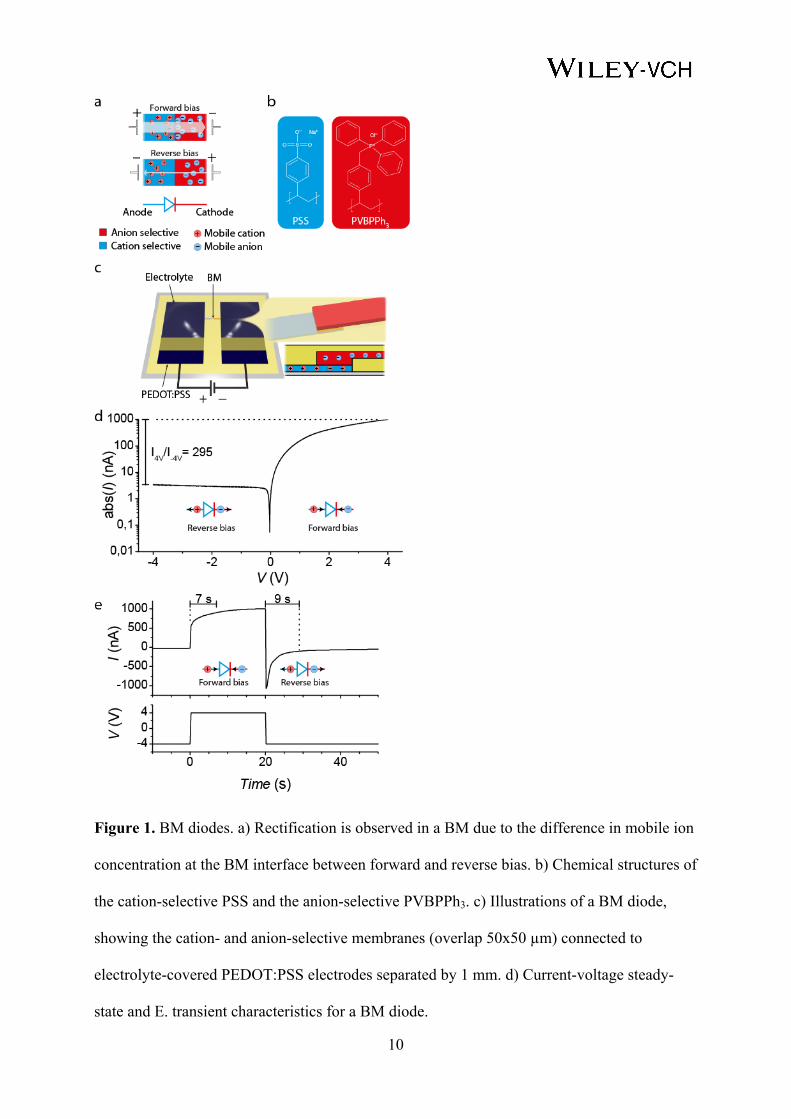
interface at reverse bias (low ionic conductivity)[24] (Figure 1a).
Highly-rectifying and swiftly operating BM-based diodes were constructed by layering
photolithographically patterned poly(styrenesulfonate) (PSS, cation-selective) with the a
quaternary polyphoshonium[21] (PVBPPh3, anion-selective) (Figure 1b) on a plastic substrate,
using SU-8 as insulator (Figure 1c). Electronically conductive poly(3,4-
ethylenedioxythiophene):poly(styrenesulfonate) (PEDOT:PSS) electrodes, covered by
aqueous electrolyte, were used for electron-to-ion conversion (and vice versa) in the circuit,
following the redox reaction PEDOT+:PSS- + M+ + e- ↔ PEDOT0 + M+:PSS-, in which ions
are exchanged between the electrode and the electrolyte. The resulting diodes exhibited good
performance, with rectification ratio (the ratio between forward and reverse bias currents),
close to 300 at ±4 V (Figure 1d) and a 10 s on/off switch time (Figure 1e).
As a first demonstration of the possibility of ionic full-wave rectification, we constructed the
typical diode bridge circuit with four BM diodes (Figure 2a). PEDOT:PSS electrodes were
patterned at each input and output terminal, in order to accommodate the electron-to-ion
conversion between the external electrical circuit and the ionic current in the bridge circuit.
As an input voltage (Vin) is applied, ionic current flows through the bridge either according to

4
Figure 2b or 2c, depending on the polarity of the input. The resulting rectified ionic current
can be determined by measuring the electronic current between the output electrodes.
To test the rectifying property of the ionic four-diode bridge, a square wave voltage of ±4 V
with 600 s period was applied at Vin, and the input (Iin) and output (Iout) current was monitored
(Figure 2d). As expected from a four-diode bridge rectifier, Iout was monopolar regardless of
the polarity of Iin, except for short transient spikes when Vin changed polarity. Further, due to
the high rectification ratio of the individual BM-diodes, the magnitude of Iout and Iin closely
matched at steady state. Thus, it is possible to use BM ion diodes to efficiently full-wave
rectify ionic currents. The efficiency, calculated as the integrated Iout divided by the integrated
absolute Iin, reached 86 %. The main loss of efficiency occurred during the switch of Vin
polarity, while the efficiency at steady state was close to 95 %. For higher input frequency,
less time is spent at steady state and the efficiency decreased to 73 % and 79 % when using
120 s and 240 s periods, respectively. Thus, the efficiency could be further increased by using
alternating input signals of even lower frequency.
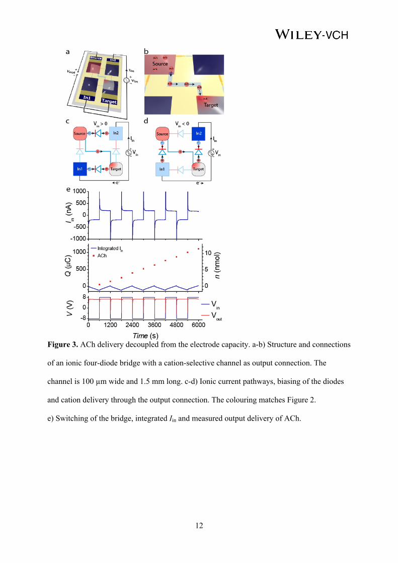
In the bridge circuit in Figure 2, the DC output is configured as an electric connection
between the two output PEDOT:PSS electrodes. The DC output of the bridge can also be
configured for ionic flux, where a cation-selective PSS channel connects the two output
reservoirs (Figure 3a-b). This connection mimics the previously reported OEIP drug delivery
device.[12] The OEIP has been utilized for electrophoretic transport and delivery of charged
biomolecules at high spatiotemporal resolution for regulation of physiology and functions in
both in vitro[12] and in vivo[25] systems. Normally, the OEIP is composed of an ion-selective
channel located between a source (S) and a target (T) electrolyte, each connected to
PEDOT:PSS electrodes used for ionic DC generation. In the present study, the electrodes are
replaced by the four-diode bridge circuit, in which an AC input signal (Vin) is rectified into an
ionic DC through the cation-selective channel between the S and T electrolytes (Figure 3c and
3d). Thus, cations are transported from the positive biased S electrolyte to the negative biased

5
T electrolyte for both positive and negative Vin. Electrodes placed in the output electrolytes
can be used to record the voltage between S and T (Vout). This DC voltage, created from the
rectified AC input signal, is the driving voltage of the cation transport through the cation-
selective channel.
The cation-selective channel inside the ionic four-diode bridge was used for electrophoretic
delivery of acetylcholine (ACh) from S to T using an AC input signal (Figure 3e). ACh is a
neurotransmitter which acts on both the peripheral and central nervous systems, is relevant for
several of the signalling cascades in humans, and has been implicated in some
neurodegenerative diseases. The bridge circuit was addressed with a ±8 V square wave Vin
signal at 1200 s period, and Iin and Vout were electrically measured. At each switch of Vin, the
whole T electrolyte (volume 5 µl) was sampled and replaced with fresh electrolyte, and the
ACh concentration in the samples was later measured using a fluorometric enzyme kit.
The ionic four-diode bridge with the cation-selective output channel shows a Vout of ~6.8 V at
steady-state. In similarity to the Iout in Figure 2d, the Vout remains positive, i.e. rectification of
Vin occurs, except for short negative spikes when the Vin switches polarity. The stable Vout
across the cation-selective channel suggests that a continuous ion current is obtained through
the channel. This was confirmed by measuring the amount of ACh delivered to the T
electrolyte. During each half-period of the Vin square signal around 120 µC, or 1.2 nmol, of
electronic charge alternatingly reduces and oxidizes the input electrodes, thus driving the
circuit. In the T electrolyte, a continuous delivery of ACh is detected, with a mean transport of
1.1 nmol per half-period. Over the total run of the experiment, 11.4 nmol ACh, equalling 1.1
mC, was delivered using only 120 µC electrode capacity (within the PEDOT:PSS electrodes
polarization regime, see Figure S1). The efficiency over the 5 periods, calculated as measured
ACh divided by the integrated absolute Iin, reaches 83 %. Thus, the ionic four-diode bridge
enables nearly-undisturbed delivery of ions over an extended period of time without the
concern of limited electrode capacity or electrode side-reactions. Also, the incorporation of an

6
ionic output circuit only marginally reduced the efficiency of the bridge circuit, and the added
loss off efficiency can mainly be attributed to less than ideal selectivity of the cation-selective
channel. Due to the long distance between the channel outlet and the BM diodes (1 mm) and a
relatively much higher concentration of Na+ (0.1 M) as compared to ACh (maximum ~ 0.22
mM) in T, transport of delivered ACh from T is negligible.
In conclusion, the use of BM ion diodes enables the construction of an ionic four-diode bridge
circuit, which can be used for full-wave rectification of ionic currents. The rectification of
input square wave signals was confirmed by measuring output of both electric and ionic
currents. Compared to previously reported mechanical valve based ionic rectifying
bridges[26,27] our diode-based bridge has no moving parts and is relatively much simpler,
offers a greater possibility of miniaturization, and is thus more suited for implantable devices.
Bridges based on rectifying transmembrane proteins have also been reported[28]. Although
very interesting from a scientific point of view these bridges have limited operational voltage
window[29]. However, compared to mechanical valves[26] and protein based bridges[28], which
have shown to operate at 1 and 0.1 Hz, respectively, the device reported here suffers from low
efficiency at high frequencies. This is due to a long switching time of our present large-sized
BM diodes. The speed and therefore the high frequency efficiency can be improved by
minimizing the size of the BM interfaces[21]. Further, as the presented device is fabricated
using high-resolution photolithography techniques, reducing the dimensions of the bridge
circuit down to 1 mm2 is well within reach. The delivery of the neurotransmitter ACh through
a cation-selective channel (Figure 3) represents a simple example of the capability and
promise of the ionic four-diode bridge. While the reported ACh delivery time-scale is
magnitudes longer than found in synaptic signalling, ACh also exhibits slower dynamics as a
neuromodulator in the brain[30], for which the presented system might be more relevant. The
function of the ionic four-diode bridge can be further extended by exchanging the cation-
selective channel with any ionic circuit that requires constant driving current for extended

7
durations, such as devices for electrokinetic driven transport. The bridge could, for example,
be integrated into ionic drug delivery devices for in vivo applications,[25] to minimize the
electrode size and to extend the device lifetime. Further, the bridge could drive ionic circuits
incorporating advanced logic functions comprising ion transistors[31] and diodes.[19,20] In such
applications, the device area is largely consumed by the electrodes and the ionic four-diode
bridge could help to minimize the required electrode area. Moreover, with an ionic rectifier at
hand, the performance of various conducting polymer electrochemical devices can be
improved. We therefore see the ionic four-diode bridge as a useful iontronic circuit element in
the development of future ionic bioelectronics, charge storage, sensor and interface devices.
Experimental Section
Preparation of PVBPPh3: The same procedure as previously reported[21] was used for
obtaining the quaternized polyphosphonium. Briefly, 5 ml of a 200 mg/ml solution of
poly(vinylbenzyl chloride) (PVBC, avg. MW ~100000, Sigma-Aldrich) in tetrahydrofuran,
filtered through a 0.2 µm polytetrafluoroethylene membrane, was mixed with 1720 mg of
triphenylphospine (Sigma-Aldrich). The mixture was heated in a water bath for 24 h at 60 °C,
after which excess solvent was removed and the product dried in vacuum. After addition of
4.5 ml H2O and 2.46 ml 1-propanol, the mixture was filtered through a 0.2 µm nylon
membrane, and additional 6 ml of H2O and 8 ml of 1-propanol was added.
Manufacturing of devices: The general procedure for manufacturing ion diodes with
PVBPPh3 has been reported before[21] and was followed without any modifications. Briefly,
PEDOT:PSS on polyethylene terephthalate substrates (AGFA-Gevaert OrgaconTM F-350) was
patterned by standard photolithography using a Karl Suss MA/BM 6 mask aligner and a
CF4/O2 plasma etch to define electrodes and cation-selective channels. The cation-selective
channels were selectively overoxidized using aqueous sodium hypochlorite solution (1 vol%)
for 45 s, in order to render the PEDOT electronically non-conductive while retaining the ionic
conductivity of PSS[32]. A 2.5 µm thick SU8-layer (SU8-2002, MicroChem) was patterned on
8
top. The anion-selective membrane (PVBPPh3) was deposited by spin coating, patterned using
photolithography and a CF4/O2 plasma, and sealed with a 10 µm thick SU8-layer (SU8-2010,
MicroChem). Silver contacts and Ag/AgCl were painted on the electrodes.
Characterization of devices: Devices were soaked in H2O for at least 24 h before
measurements. A Keithley 2602A source meter, programmed via LabVIEW, was used for
sourcing and measuring voltages and currents with a 4 Hz sampling frequency.
ACh measurements: A fluorometric ACh assay kit (Amplex® Red
acetylcholine/acetylcholinesterase assay kit, Molecular Probes) was used to measure the ACh
concentration in the collected samples. The assay was performed with excitation at 550 nm
and emission at 590 nm using a Tecan Safire 2 plate reader after 60 minutes incubation.
Supporting Information Supporting Information is available from the Wiley Online Library or from the author.
Acknowledgements This research was financed by VINNOVA 2010-00507 (OBOE Miljö), the EU Seventh Framework Programme (FP7/2007-2013) under grant agreement 280772 project iONE-FP7, the Swedish Research Council (621-2011-3517), the Swedish foundation for strategic research (RMA-11:0104), the EU Seventh Framework Programme Marie Curie (PITN-GA-2013-607896) project OrgBIO, the Advanced Functional Materials Center at Linköping University, and the Önnesjö foundation. We also thank Rozalyn Simon at Linköping University for experimental support regarding the acetylcholine assay.
Received: ((will be filled in by the editorial staff)) Revised: ((will be filled in by the editorial staff))
Published online: ((will be filled in by the editorial staff))
[1] Chuan-Hua Chen, J. G. Santiago, J. Microelectromech. Syst. 2002, 11, 672. [2] R. Hagedorn, T. Schnelle, T. Müller, I. Scholz, K. Lange, M. Reh, Electrophoresis
2005, 26, 2495. [3] P. E. Boukany, A. Morss, W.-C. Liao, B. Henslee, H. Jung, X. Zhang, B. Yu, X.
Wang, Y. Wu, L. Li, K. Gao, X. Hu, X. Zhao, O. Hemminger, W. Lu, G. P. Lafyatis, L. J. Lee, Nature Nanotech 2011, 6, 747.
[4] A. Persat, M. E. Suss, J. G. Santiago, Lab Chip 2009, 9, 2454. [5] D. Kohlheyer, J. C. T. Eijkel, A. van den Berg, R. B. M. Schasfoort, Electrophoresis
2008, 29, 977. [6] J. Voldman, Annual Review of Biomedical Engineering 2006, 8, 425.

9
[7] T. Revermann, S. Götz, J. Künnemeyer, U. Karst, Analyst 2008, 133, 167. [8] A. R. Minerick, A. E. Ostafin, H.-C. Chang, Electrophoresis 2002, 23, 2165. [9] A. Oki, Y. Takamura, Y. Ito, Y. Horiike, Electrophoresis 2002, 23, 2860. [10] P. G. Erlandsson, N. D. Robinson, Electrophoresis 2011, 32, 784. [11] M. R. Abidian, D. H. Kim, D. C. Martin, Adv Mater 2006, 18, 405. [12] J. Isaksson, P. Kjaell, D. Nilsson, N. D. Robinson, M. Berggren, A. Richter-Dahlfors,
Nature Materials 2007, 6, 673. [13] G. Sonmez, C. K. F. Shen, Y. Rubin, F. Wudl, Angew. Chem. Int. Ed. 2004, 43, 1498. [14] J. M. D’Arcy, M. F. El-Kady, P. P. Khine, L. Zhang, S. H. Lee, N. R. Davis, D. S.
Liu, M. T. Yeung, S. Y. Kim, C. L. Turner, A. T. Lech, P. T. Hammond, R. B. Kaner, Acs Nano 2014, 8, 1500.
[15] G. Tarabella, F. M. Mohammadi, N. Coppede, F. Barbero, S. Iannotta, C. Santato, F. Cicoira, Chem Sci 2013, 4, 1395.
[16] S. Park, T. Chung, H. Kim, Microfluid Nanofluid 2009, 6, 315. [17] L. Hegedüs, N. Kirschner, M. Wittmann, P. Simon, Z. Noszticzius, T. Amemiya, T.
Ohmori, T. Yamaguchi, Chaos 1999, 9, 283. [18] H. Daiguji, Y. Oka, K. Shirono, Nano Lett 2005, 5, 2274. [19] J. H. Han, K. B. Kim, H. C. Kim, T. D. Chung, Angew. Chem. Int. Ed. 2009, 48,
3830. [20] E. O. Gabrielsson, K. Tybrandt, M. Berggren, Lab Chip 2012, 12, 2507. [21] E. O. Gabrielsson, M. Berggren, Biomicrofluidics 2013, 7, 064117. [22] R. Schoch, J. Han, P. Renaud, Rev. Mod. Phys. 2008, 80, 839. [23] V. J. Frilette, J. Phys. Chem. 1956, 60, 435. [24] P. Ramirez, H. Rapp, S. Reichle, H. Strathmann, S. Mafé, J. Appl. Phys. 1992, 72,
259. [25] D. T. Simon, S. Kurup, K. C. Larsson, R. Hori, K. Tybrandt, M. Goiny, E. W. H.
Jager, M. Berggren, B. Canlon, A. Richter-Dahlfors, Nat Mater 2009, 8, 742. [26] G. Y. Fridman, C. C. Della Santina, IEEE Transactions on Neural Systems and
Rehabilitation Engineering 2013, 21, 319. [27] A. Brask, D. Snakenborg, J. P. Kutter, H. Bruus, Lab Chip 2006, 6, 280. [28] G. Maglia, A. J. Heron, W. L. Hwang, M. A. Holden, E. Mikhailova, Q. Li, S.
Cheley, H. Bayley, Nature Nanotech 2009, 4, 437. [29] S. Punnamaraju, A. J. Steckl, Langmuir 2011, 27, 618. [30] M. R. Picciotto, M. J. Higley, Y. S. Mineur, Neuron 2012, 76, 116. [31] K. Tybrandt, R. Forchheimer, M. Berggren, Nat Commun 2012, 3. [32] P. Tehrani, A. Kanciurzewska, X. Crispin, N. D. Robinson, M. Fahlman, M.
Berggren, Solid State Ionics 2007, 177, 3521.
10
Figure 1. BM diodes. a) Rectification is observed in a BM due to the difference in mobile ion
concentration at the BM interface between forward and reverse bias. b) Chemical structures of
the cation-selective PSS and the anion-selective PVBPPh3. c) Illustrations of a BM diode,
showing the cation- and anion-selective membranes (overlap 50x50 µm) connected to
electrolyte-covered PEDOT:PSS electrodes separated by 1 mm. d) Current-voltage steady-
state and E. transient characteristics for a BM diode.

11
Figure 2. The four-diode full wave ion current rectifier. a) Structure and connections of an
ionic four-diode bridge with electronic output connection. b-c) Ionic current pathways
depending on Vin polarity. Electrodes being reduced/oxidized are shown in dark/pale blue,
reverse biased diodes are indicated by faded colors. d) Electronic AC input and DC output
through the bridge.
12
Figure 3. ACh delivery decoupled from the electrode capacity. a-b) Structure and connections
of an ionic four-diode bridge with a cation-selective channel as output connection. The
channel is 100 µm wide and 1.5 mm long. c-d) Ionic current pathways, biasing of the diodes
and cation delivery through the output connection. The colouring matches Figure 2.
e) Switching of the bridge, integrated Iin and measured output delivery of ACh.

13
Full-wave rectification of ionic currents is obtained by constructing the typical four-diode bridge out of ion conducting bipolar membranes. Together with conjugated polymer electrodes addressed with alternating current, the bridge allows for generation of a controlled ionic direct current for extended periods of time without the production of toxic species or gas typically arising from electrode side-reactions. Keywords: bioelectronics, ionics, ion transport, bipolar membranes, conjugated polymer electrodes Erik O. Gabrielsson, Per Janson, Klas Tybrandt, Daniel T. Simon and Magnus Berggren* A Four-Diode Full-Wave Ionic Current Rectifier Based on Bipolar Membranes: Overcoming the Limit of Electrode Capacity

14
Copyright WILEY-VCH Verlag GmbH & Co. KGaA, 69469 Weinheim, Germany, 2013. Supporting Information A Four-Diode Full-Wave Ionic Current Rectifier Based on Bipolar Membranes: Overcoming the Limit of Electrode Capacity Erik O. Gabrielsson, Per Janson, Klas Tybrandt, Daniel T. Simon and Magnus Berggren* E. O. Gabrielsson, P. Janson, Dr. K. Tybrandt, Dr. D. T. Simon, Prof. M. Berggren Laboratory of Organic Electronics, Linköping University, SE-601 74 Norrköping, Sweden E-mail: [email protected]
0 2 4 6 8 101
10
100
1000
Q (µ
C)
Time (s) Figure S1. PEDOT:PSS electrode capacity. Oxidation of pristine (partly oxidized)
PEDOT:PSS electrodes (6.25 cm2 area) in 0.1 M NaCl at 1.5 V vs an Ag/AgCl (in 3 M NaCl)
reference electrode. After ~200 µC the rate decreases, indicating the limit of the PEDOT:PSS
electrodes polarization regime. Measurements were performed using a µAutolabIII
potentiostat (Metrohm Autolab).