a finite-difference scheme for two …me.buet.ac.bd/icme/icme2001/cdfiles/papers/keynote/... ·...
TRANSCRIPT

4th International Conference on Mechanical Engineering, December 26-28, 2001, Dhaka, Bangladesh
Keynote Paper
Keynote Paper
TOWARDS A NEW FINITE-DIFFERENCE SCHEME FOR TWO-DIMENSIONAL STRESS ANALYSIS OF COMPOSITE STRUCTURES
Noor Al Quddus, S. Reaz Ahmed, Md. Wahhaj Uddin
Department of Mechanical Engineering, Bangladesh University of Engineering & Technology, Dhaka-1000, Bangladesh
Abstract: This paper contains a new approach to the finite difference solution of stresses in composite structures. Compared to the conventional computational schemes, the present scheme gets solution of much higher accuracy and in extremely shorter time. Keywords Finite-difference, finite-element, composite structures, stress analysis.
INTRODUCTION
Presently, in case of very simple structures like beam, column, circular discs, regular shaped plates and thin shells of simple geometry and boundary, analytical methods are used for their stress analysis. However two-dimensional stress analysis of solids is mainly handled by numerical methods. The major numerical methods in use are (a) the method of finite-difference and (b) the method of finite element. But finite element method is more popular as it can handle irregular boundary shapes far better compared to finite difference method. However, the supremacy is brought back to the finite-difference technique here from the finite element method through a new formulation of the two-dimensional problem of stress analysis of solid structures. As the new formulation establishes a priority of finite-difference technique over finite element technique, the philosophy and approach of the two methods are recapitulated here in brief.
PHILOSOPHY OF
FINITE ELEMENT METHOD 1. The body is divided into elements (8 elements here
in Fig.1). 2. The elements are connected to each other only at
the nodes (Body is not a single piece but an
Fig.1 A body is divided into elements
assembly of smaller pieces). 3. Any parameter like stress, temperature, density,
displacement varies according to a given simple relation like linear, parabolic, etc., along the length, breadth and height of the elements.
4. Values of parameters are evaluated only at the nodes satisfying the conditions that, (i) Each node has an unique value for each parameter. (ii) The values of the parameters at the nodes are such that continuity, conservation, equilibrium, etc., are maintained.
PHILOSOPHY OF
FINITE-DEFFERENCE METHOD 1. The body is in one single piece but the parameters
are evaluated only at some selected points, called nodes, within the body.
2. Values of the parameters at the nodal points are based on continuity, conservation (mass, energy, momentum, etc.), equilibrium, leastness, etc.
Fig.2 Nodes in a body where parameters are found in
finite-difference technique.

ICME 2001, Dhaka, December 26-28
Keynote Paper
COMPARISON BETWEEN FINITE-ELEMENT AND FINITE-DIFFERENCE TECHNIQUES
Finite Element Method Disadvantages: (a) The body is not in one piece but an assemblage of
elements connected at the nodes. (b) Variation of parameter over individual elements
assumed to be very simple like linear, quadratic etc. (c) Values of parameters across element boundary may
be discontinuous. (d) Number of parameters (like u, v, w) to be evaluated
at each nodal point is usually more than that in finite-difference.
(e) The total number of unknowns to be solved is much more than that in finite-difference and hence the solution is crude and less authentic and the computation time is more.
Advantages: (a) It works when other methods fail. (b) It is very good in managing complicated boundary. Finite-Difference Method Disadvantages: (a) Derivatives in the governing equations are replaced
by their finite-differences and hence some approximation.
(b) Complicated boundary shapes and conditions are very difficult, almost impossible to handle.
(c) Can not handle singularity very well. Advantages: (a) The body is in one piece and thus no approximation
on this account. (b) The number of parameters to be evaluated at each
nodal point is usually less than that in finite element.
(c) Total number of unknowns is less and hence, solution is more accurate and computational time is less.
OUR OBJECTIVE
Our objective is to develop a finite-difference scheme for two-dimensional stress-analysis of composite structures which requires much less computational works than existing ones. Why Finite-Difference? There are two reasons: 1. Because it permits reduction of parameters to be
evaluated at the nodal points to one. 2. Because it provides more accurate results than
finite elements and involves less computational work.
The Difference Between The Present Scheme And The Existing Schemes
The differences are: 1. The present scheme reduces the problem to finding
a single parameter at the nodal points whereas the existing schemes find more than one at each node and hence a tremendous amount of additional computational work.
2. Existing schemes can not handle odd shapes of boundaries and mixed mode boundary conditions. The present scheme handles both these two conditions very well. In fact, the present scheme removes the reason for which the finite element system was born.
SCHEME FOR REDUCTION OF COMPUTATIONAL WORK
Both in finite element and in finite-difference methods, the problem is reduced to the solution of a set of algebraic equations. The unknowns are the values of parameters at the nodes. The equation is An, n Xn = Bn for n unknowns …………(1)
For an additional unknown, the equation becomes An+1, n+1 Xn+1 = Bn+1 ……………………...(2) To reduce equation (2) to (1), we have to perform (a) (n+1)(n+1) = (n+1)2 divisions (b) (n)(n) = n2 subtractions When n = 0, then increase in computation is one division. That is, when we have only one unknown, computation involves is one division. When n = 1, the increase is 4 divisions and 1 subtraction. Total Number of Nodes = N Number of Parameters at each Node (like u, v) = p Therefore, total number of unknowns n in the equation An, n Xn = Bn ,is given by n = NP For a two dimensional problem, in both existing finite-difference and finite element techniques, P = 2 In our scheme, P = 1 Therefore, unknowns in existing schemes, ne = 2 N Unknown in our scheme, n0 = N Saving in unknown, ns = ne – no = N Saving in computation Division = (N+1)2 + (N+2)2 + ….+(2N)2 Subtraction = N2 + (N+1)2 + ….+(2 N – 1)2
ICME 2001, Dhaka, December 26-28
Keynote Paper
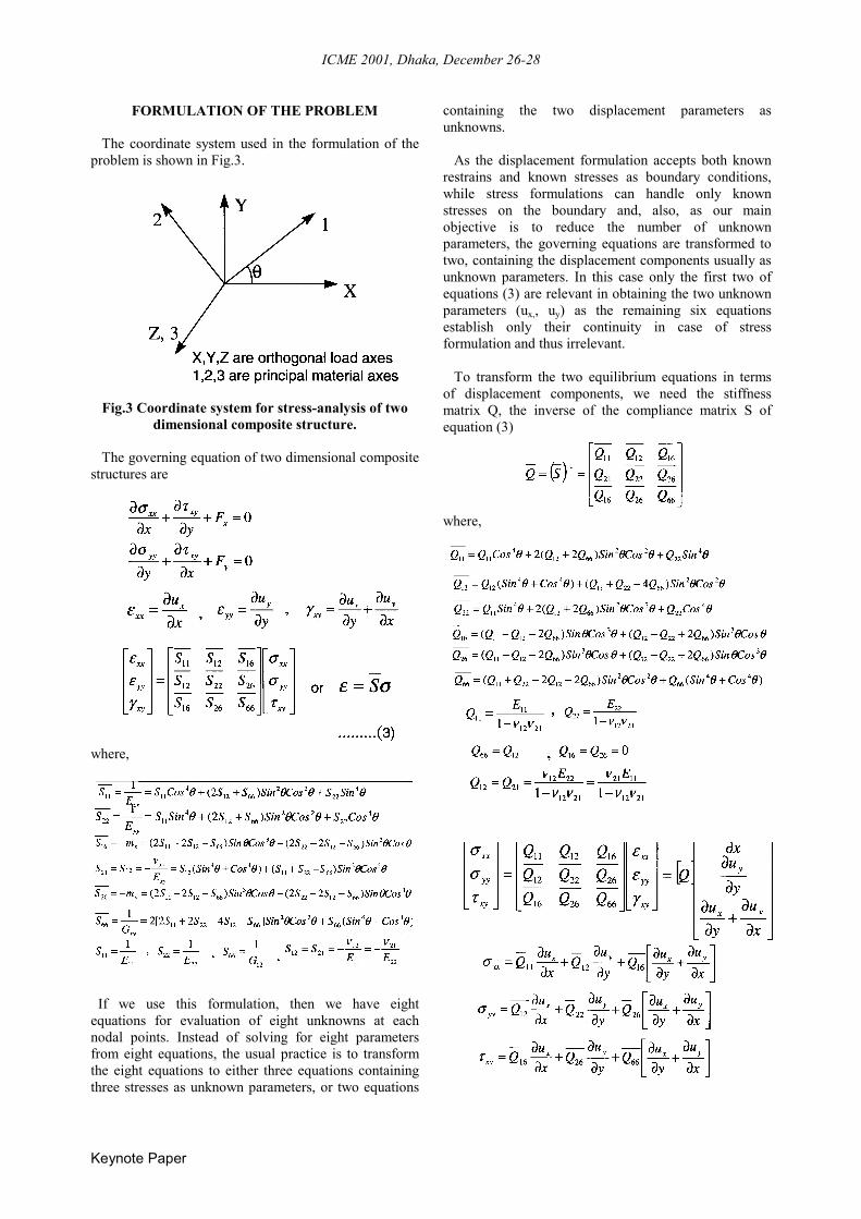
FORMULATION OF THE PROBLEM The coordinate system used in the formulation of the problem is shown in Fig.3.
Fig.3 Coordinate system for stress-analysis of two dimensional composite structure.
The governing equation of two dimensional composite structures are
where,
If we use this formulation, then we have eight equations for evaluation of eight unknowns at each nodal points. Instead of solving for eight parameters from eight equations, the usual practice is to transform the eight equations to either three equations containing three stresses as unknown parameters, or two equations
containing the two displacement parameters as unknowns. As the displacement formulation accepts both known restrains and known stresses as boundary conditions, while stress formulations can handle only known stresses on the boundary and, also, as our main objective is to reduce the number of unknown parameters, the governing equations are transformed to two, containing the displacement components usually as unknown parameters. In this case only the first two of equations (3) are relevant in obtaining the two unknown parameters (ux,, uy) as the remaining six equations establish only their continuity in case of stress formulation and thus irrelevant. To transform the two equilibrium equations in terms of displacement components, we need the stiffness matrix Q, the inverse of the compliance matrix S of equation (3)
where,

ICME 2001, Dhaka, December 26-28
Keynote Paper
After substitution of the stresses, the equilibrium equations in terms of displacements are
162y
2
662x
2
16x
2
2x
2
11 Qx
uQ
yu
Q2yx
uxu
Q−−−−
∂
∂+
∂
∂+
∂∂
∂+
∂∂
0Qy
uQQ
yxu
262y
2
1266y
2
=
∂
∂+
+∂∂
∂+
−−−
∂
∂+
+∂∂
∂+
∂∂ −−−−
262x
2
1266x
2
2x
2
16 Qyu
QQyx
uxu
Q
0Qy
uQ2
yxu
Qx
u222
y2
26y
2
662y
2
=
∂
∂+
∂∂
∂+
∂
∂+
−−−
….(4) Let us now assume that
where, α ‘s are unknown constants. Substituting ux and uy in the equilibrium equations (4), we get the equilibrium equations in terms of ψ
…..(5b)
Let us now choose α ‘s in such a way that equation 5(a) is automatically satisfied under all circumstances. This will happen when coefficients of all the derivatives are individually zero. That is when
…..(6) Thus, for ψ to be a solution of the stress problem, it has to satisfy equation 5(b) only. However, the α ‘s of
equation (6) must be known to us. Here, we have 5 equations for obtaining six unknowns. We can thus assign an arbitrary value to one of these six unknowns and solve for the remaining unknowns from equation (6). Assuming α1 = 1 and writing equation (6) in matrix form, we get
The problem has now been reduced to the solution of a single equation for a single parameter ψ from equation 5(b). Let this equation be written as
…..(7) where, β ‘s are given by
Finite-difference discretization of equation (7) is
…..(8) where, h and k are the nodal distances in the x- and y-direction, respectively and α=h/k. Fig.4 shows the nodal system to be used for the discretization of the equilibrium equation (7).
Fig.4 Two dimensional nodal points in rectangular coordinate system

ICME 2001, Dhaka, December 26-28
Keynote Paper
Saving In Computational Effort In Comparison To Existing Schemes Basically, finite element technique involves finding two parameters (ux, uy) at each nodal point. Here, in the finite-difference scheme, we have to find only one parameter, ψ. So the reduction of the unknowns between the two techniques are from 2N of finite element to N of the present finite-difference scheme. Let us now evaluate the percentage reduction in computational effort. Saving in the number of division
( )( )( ) ( )( )6
1N21NN6
1N41N2N2 ++−++=
Percentage saving in division alone
( )( )( ) ( )( )( )( ) 100
1N41N2N21N21NN1N41N2N2 ×
++
++−++=
( ) %1001N42
1N1 ×
+
+−=
≅ 87.5%, when N is large
CONCLUSION
The present approach to the solution of stress problems of two dimensional composite structures by the finite-difference technique will save us approximately 87.5% of time in comparison to that taken by finite element method and in addition, the quality and accuracy of solutions will be highly improved because of the fact that, the solution of any algebraic system deteriorates with increasing number of unknowns and eventually fails when the number of unknowns become very large. If we remember that, as of today, the only constraints to the solutions of yet unsolved problems of engineering and science is the limitation of capacity to solve for the large number of unknowns in a system of linear algebraic equations because of the truncation error and of round-off error in the process of calculation. In that context, the present approach will not only increase our horizon of managing bigger problems in stress analysis but also in other fields of science. So, the present approach saves us time as well as increases the horizon of our capabilities in terms of solving bigger problems with higher accuracy.