a experimental study of disc in-plane mode induced …
TRANSCRIPT
EB2013-NVH-10
A EXPERIMENTAL STUDY OF DISC IN-PLANE MODE INDUCEDBRAKE SQUEAL,
Ryutaro, Misumi; Toru, MatsushimaToyota Motor Corporation, Japan
KEYWORDS – disc brake, brake squeal, in-plane mode, bending mode, countermeasuredesign
ABSTRACT
It is one of the most important issues to reduce brake squeal in brake development. Brakesqueal is classified in two kinds of vibration mode of the disc. One is out-of-plane modewhich vibrates in out-of plane direction of disc. The other is in-plane mode which vibrates incircumferential or radial direction of the disc. For out-of-plane mode, a number of existingcountermeasures can be potentially applied after characterization of the squeal occurrencecondition by direct experiment or simulation analysis. On the other hand, in-plane mode, isoccurred under high frequency, often involves the tangential (also called circumferential orlongitudinal) vibration modes of brake rotor. Therefore, the characterization of the squealoccurrence condition has not been completely understood and still remains as one ofimportant issues in the automotive industry due to it is much complicated mechanisms. In thispaper, we show the experimental analysis results of the vibration mode of parts in a brakesystem while squeal is occurring when the disc vibrates in in-plane mode. And we consider agenerating mechanism of brake squeal and countermeasure logic of reduction for disc in-plane mode brake squeal.
INTRODUCTION
Reducing brake noise to an acceptable level for the end customers is one of the main tasks ofbrake development today. As regards brake squeal, many research institutes have beenresearched and presented reducing brake squeal method[1,2,3,4,5,6,7,8] such as experimentalmodal analysis of brake system measured by laser Doppler vibrometer, oscillationmechanistic analysis using simplified friction vibration model, or simulation using FiniteElement Methods.
Brake squeal phenomena can be generally separated into 2 main mode types related to thedirection of disc vibration involved: out- of-plane and in-plane mode. For out-of-plane mode,a number of countermeasures can be potentially applied after characterization of the squealoccurrence condition by direct experiment or simulation analysis as above. However, as thereare many possible mechanisms and root causes for the in-plane mode[9,10,11,12,13,14,15,16],it is generally necessary to perform a detailed analysis of the vibration mechanism beforeimplementing a countermeasure.
In this paper, at first, we show the experimental analysis results of the vibration mode of partsin a brake system while squeal is occurring when the disc vibrates in 1st in-plane mode andconsider a generating mechanism of the disc in-plane vibration. Secondly, we compose thesimplified theoretical model and ascertain a new parameter to consider a disc in-planevibration mode. Finally, we clarify a new parameter need by experimental investigation whichchanges a pad shape configuration.
EXPERIMENTAL ANALYSIS OF IN-PLANE MODE BRAKE SQUEAL
1. Test bench
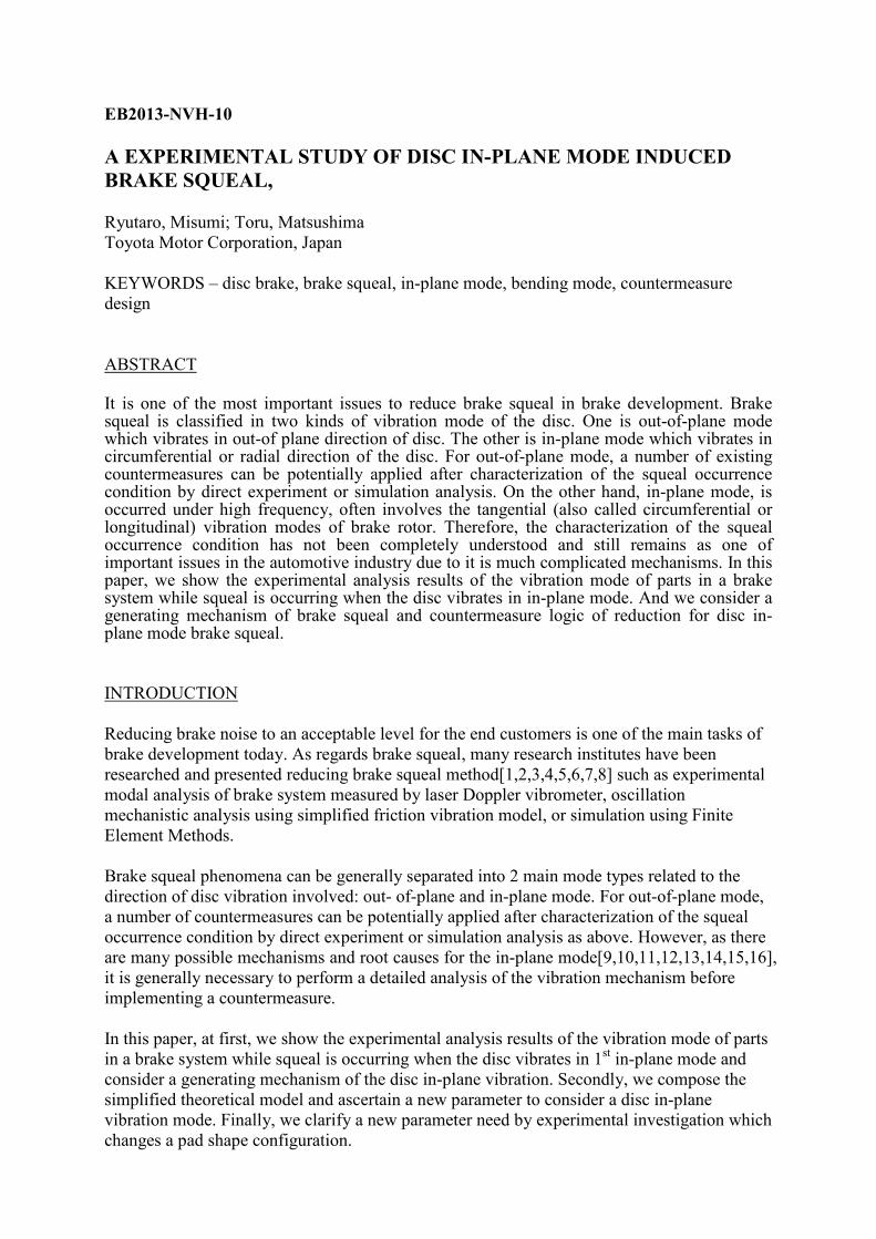
The experimental apparatus is shown in figure 1. The brake system which is composed of discrotor and calliper mounted through a drive shaft and a suspension knuckle attached to theexperimental apparatus. The disc is driven through a drive shaft which is connected to anelectrical motor. This motor could provide a variable speed between 0-50r/min. Brake squealcould reproduce by controlled brake pressure and rotation speed. The disc vibration frequencyis measured by a laser vibrometer which is pointed to the disc indirectly surface.
Figure 1: Test bench
2. Disc brake specification
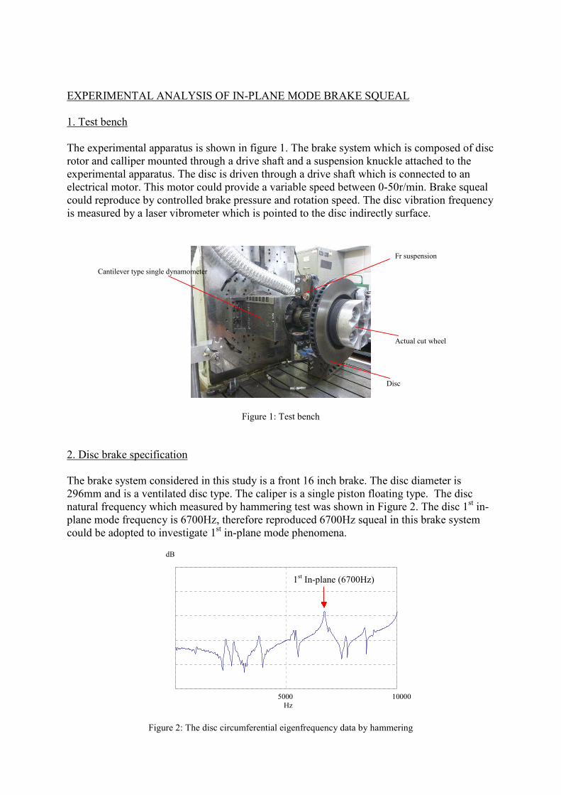
The brake system considered in this study is a front 16 inch brake. The disc diameter is296mm and is a ventilated disc type. The caliper is a single piston floating type. The discnatural frequency which measured by hammering test was shown in Figure 2. The disc 1st in-plane mode frequency is 6700Hz, therefore reproduced 6700Hz squeal in this brake systemcould be adopted to investigate 1st in-plane mode phenomena.
Fig
Cantilever type single dynamometer
Fr suspension
Actual cut wheel
Disc
ure 2: The disc circumferentia
dB
1st In-plane (6700Hz)
l eigenfrequency data by hamm
5000Hz
10000
ering
60
80
100
120
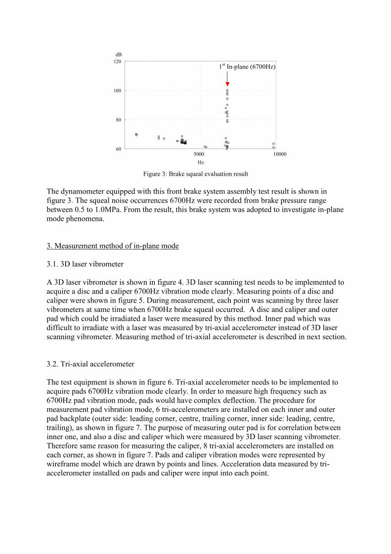
Figure 3: Brake sq
The dynamometer equipped with this front brfigure 3. The squeal noise occurrences 6700Hbetween 0.5 to 1.0MPa. From the result, this bmode phenomena.
3. Measurement method of in-plane mode
3.1. 3D laser vibrometer
A 3D laser vibrometer is shown in figure 4. 3Dacquire a disc and a caliper 6700Hz vibrationcaliper were shown in figure 5. During measuvibrometers at same time when 6700Hz brakepad which could be irradiated a laser were medifficult to irradiate with a laser was measuredscanning vibrometer. Measuring method of tr
3.2. Tri-axial accelerometer
The test equipment is shown in figure 6. Tri-aacquire pads 6700Hz vibration mode clearly.6700Hz pad vibration mode, pads would havemeasurement pad vibration mode, 6 tri-accelepad backplate (outer side: leading corner, centtrailing), as shown in figure 7. The purpose ofinner one, and also a disc and caliper which wTherefore same reason for measuring the calipeach corner, as shown in figure 7. Pads and cawireframe model which are drawn by points aaccelerometer installed on pads and caliper w
dB
1st In-plane (6700Hz)
ueal evaluation result
ake system assembly testz were recorded from brarake system was adopted
laser scanning test needmode clearly. Measuringrement, each point was scsqueal occurred. A discasured by this method. Inby tri-axial acceleromet
i-axial accelerometer is d
xial accelerometer needsIn order to measure highcomplex deflection. The
rometers are installed onre, trailing corner, inner smeasuring outer pad is fere measured by 3D laseer, 8 tri-axial acceleromeliper vibration modes wend lines. Acceleration daere input into each point.
5000
Hz
10000
result is shown inke pressure rangeto investigate in-plane
s to be implemented topoints of a disc andanning by three laserand caliper and outerner pad which waser instead of 3D laserescribed in next section.
to be implemented tofrequency such asprocedure foreach inner and outeride: leading, centre,
or correlation betweenr scanning vibrometer.ters are installed onre represented byta measured by tri-
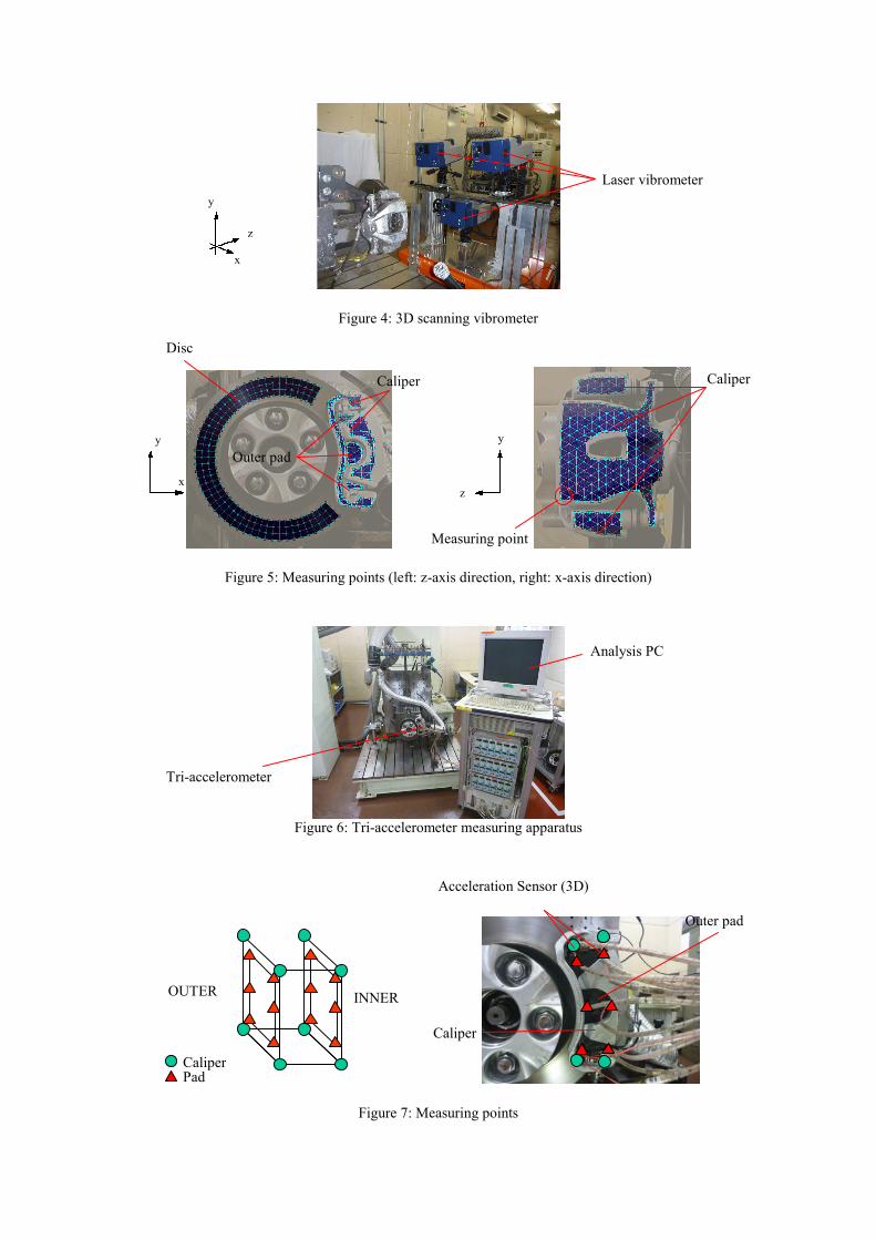
Figure 4: 3D scanning vibrometer
Figure 5: Measuring points (left: z-axis direction, right: x-axis
Figure 6: Tri-accelerometer measuring apparatus
Figure 7: Measuring points
z
y
x
x
y
z
y
Measuring point
Disc
Caliper
Outer pad
A
Tri-accelerometer
Pad
Acceleration Sensor (3D)
Caliper
OUTER INNER
direction)
Laser vibrometer
nalysis PC
Ou
Caliper
ter pad
Caliper
4. Measurement result
4.1. The disc
The disc vibration mode during brake squeal generated at 6700Hz is shown in figure 8. Asfigure 8, a displayed number (1) is set at a disc maximum deformation in positive y-axisdirection, (2) is 0.000037sec later from (1), (3) is 0.000074sec later from (1), and (4) is0.000112sec later from (1). As the result of measurement in the case where a pad centre is 0degree, “node” which has maximum circumferential amplitude would be located at 0 degreeand 180 degrees, “Anti-node” which has zero or minimum circumferential amplitude wouldbe located at 90 degrees and 270 degrees. A phase difference of disc slide surfacecircumferential amplitude between 0 degree and 180 degree is inverted. And when “anti-node” located at 90 degrees has contraction mode, in oppositional 270 degrees has extensionmode. Then one pair of contraction and extension wave could be confirmed, the disc vibrationmode during squeal generation at 6700Hz is 1st in-plane.
4.2. The caliper
A caliper vibration mode during brake squeal generated at 6700Hz is shown in figure 9. Adisplayed number (1) is set at a disc maximum deformation in positive y-axis direction asshown in figure 8, (2) is 0.000037sec later from (1), (3) is 0.000074sec later from (1), and (4)is 0.000112sec later from (1) Measuring a disc and a caliper is implemented at same time.And the range of amplitude is same as disc. As the result of measurement, mounting abutmentdeflection has y-direction, and cylinder fingers have z-direction. However both values were0.2 times less than disc amplitude, a caliper was less influenced to in-plane mode brake squeal.
4.3. Brake pads
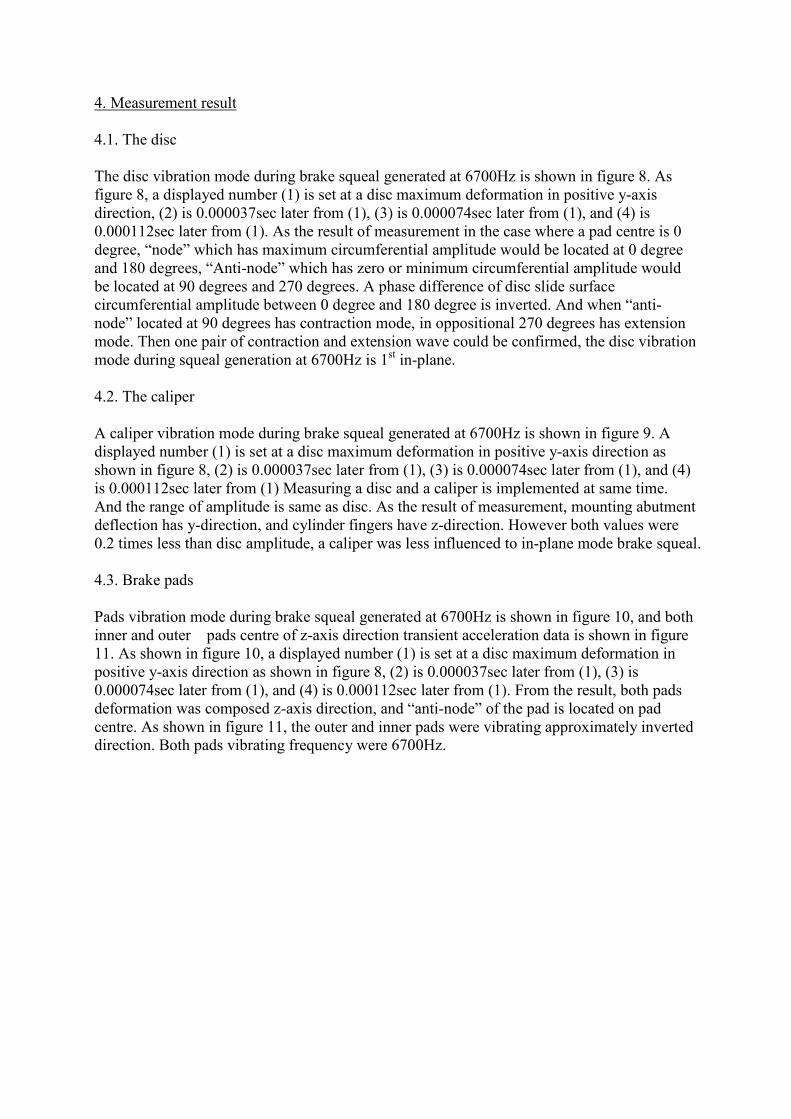
Pads vibration mode during brake squeal generated at 6700Hz is shown in figure 10, and bothinner and outer pads centre of z-axis direction transient acceleration data is shown in figure11. As shown in figure 10, a displayed number (1) is set at a disc maximum deformation inpositive y-axis direction as shown in figure 8, (2) is 0.000037sec later from (1), (3) is0.000074sec later from (1), and (4) is 0.000112sec later from (1). From the result, both padsdeformation was composed z-axis direction, and “anti-node” of the pad is located on padcentre. As shown in figure 11, the outer and inner pads were vibrating approximately inverteddirection. Both pads vibrating frequency were 6700Hz.

Figure 8: 6700Hz
Figure 9: 6700Hz v
Fig.10 6700Hz vibration m
0
90°
180°
270°
Disc
x
y
z
90°
180°
x
y
z
Caliper
Caliper
Outer pad
x
y
z
Inner pad
270°
°
vibration mode (Disc)
i
o
0
bration mode (Caliper)
°
de (the caliper, outer and inner pads)
-15
-12
-9
-6
-3
0
3
0 0.0001time:sec
acceleration
Fig.11 The outer and inner pads v
CONSIDERATION OF GENERATION MECHA
Brake system vibration mode during brake squemainly a disc 1st in-plane mode and pads 1s
mechanism of 1st in-plane mode, the caliper vibravery small. Therefore, the disc and the outer andconsidered the force transmission relative between
Based on (1) and (3) of figure 8 and 10, thcircumferential direction, and pads had any deforminner and outer pad bending force is generated at d
Based on (2) and (4) of figure 8 and 10, a disc dvibrated with z-axis direction bending deformationbe caused at a disc and pad contact surface. This pfriction variation force then transmitted to the disc.
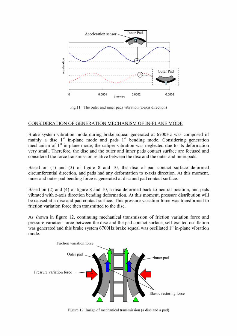
As shown in figure 12, continuing mechanical trpressure variation force between the disc and thewas generated and this brake system 6700Hz brakemode.
Figure 12: Image of mechanical tran
Acceleration sensor
Outer pad
Pressure variation force
Friction variation force
0.0002
4
7
10
13
ibration (z-axis dir
NISM OF IN-PL
al generated att bending modtion was negleinner pads contthe disc and the
e disc of padation to z-axis
isc and pad cont
eformed back to. At this momenressure variatio
ansmission ofpad contact surfsqueal was osc
smission (a disc an
Inner Pad
I
Elas
0.0003
-5
-2
1
ection)
ANE MODE
6700Hz was composed ofe. Considering generationcted due to its deformationact surface are focused andouter and inner pads.
contact surface deformeddirection. At this moment,
act surface.
neutral position, and padst, pressure distribution willn force was transformed to
friction variation force andace, self-excited oscillationillated 1st in-plane vibration
Outer Pad
nner pad
d a pad)
tic restoring force
Here, two noticeable factors could be found. The first is as shown in figure 11, the outer andinner pads vibrating phases were inverted during brake squeal generated at 6700Hz. In thissituation, the outer and inner friction variation force acted to the disc circumferential directionat a time. The second is the outer and inner pads behaved 1st bending deformation. If the padvibrated in rigid mode, its circumferential displacement could be assumed small. However, apad during 1st bending deformation could not be assumed small so that this means the elasticrestoring force might act to the disc surface as shown in figure 12. These two factors could besupposed to generate the disc in-plane mode easily Thus, to clarify the relationship betweenthe in-plane mode and the elastic restoring force is investigated by using theoretical modelwhich is described in next section.
THEORETICAL MODEL
In here, the in-plane brake squeal theoretical model is discussed, which is based on theconcept of Millner’s approach [1]. The brake squeal phenomenon is able to represent by thefollowing linear vibration system equation:
FUKUCUM (1)
Where [M], [C], and [K] are respectively the mass, damping and stiffness matrices of thebrake system.[U] is a displacement vector representing displacements of brake system partsand f is an external exiting force vector representing the variation in the friction force betweenthe disc and pads.
Here, damping matrix [C] can be initially ignored for the brake squeal analysis, since valuesof [C] are determined by each part’s material properties and their contact situation. Thus, thevibration equation can be rewritten as
FUKUM (2)
The friction force variation f between the disc and pads is direct cause of vibration thatinitiates brake squeal occurrences, and can be described as
μΔNΔμNF (3)
Where μ and N are respectively the friction coefficient and contact force vector between the
disc and pads. In here, friction coefficient is assumed constant and the force variation can berewritten as
μΔNF (4)
Substituting equation (4) into (2) yields,
ΔNμUKUM (5)
Since brake squeal is a type of self-excited vibration phenomenon, the amplitude of vibrationin the system rapidly increases once the initial self-excitation has occurred. To express theamplitude of displacement in function of time t such that
λtetU u (6)
Where u and λ are the amplitude of displacement and a complex eigenvalue of the vibrationsystem. By substituting equation (6) into (5), a brake system equation is obtained to be able toinvestigate the self-excited vibration phenomenon of brake squeal.
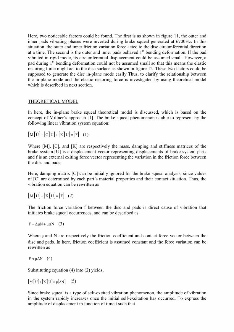
Based on experimental result, an in-plane simplified theoretical model is represented asfigure13 and Table 1. The model is composed of a disc, an inner pad, a caliper and a padsupport bracket. In here, an outer pad is not included due to vibration deformation as same asthe inner pad. The pad is supported by a support bracket and represented the stiffness in x-axis direction (Kt). The contact surface between the pad and the caliper is represented thestiffness in z-axis direction (Kcp). To represent pad bending mode, z-axis origin is set on thepad centre and the rotational spring ( Kpθ ) is set z-axis line symmetry. The contact surface
between the disc and the pad is a set of spring and represented the stiffness in z-axis direction(Kpr) and x-axis direction (K’pr). This K’pr expresses that a pad elastic restoring force act tothe disc.
Table 1: Nomenclatu
------------Xr: x-axis displacemeXp: x-axis displacemXc: x-axis displacemZr: z-axis displacemeZp: z-axis displacemeZc: z-axis displacemeθ r: angle of rotationθ p: angle of rotationθ c: angle of rotationa: contact position of
Inner
D
Pad support bra
Caliper / piston
/Outer pad
cket
isc
Figure 13: Simplified theoretical model
re
nt of the discent of the padent of the calipernt of the discnt of the padnt of the calipeof the discof the padof the caliperthe caliper and the pad
Disc rotating direction
b: thickness of the caliperc: thickness of the padd: thickness of the discF: pressure forceF’: friction force between the disc and the padμ : friction coefficient between the disc and the pad
P: pressure force between the caliper and the padP’: friction coefficient between the caliper and the pad ’: friction coefficient between the caliper and the pad
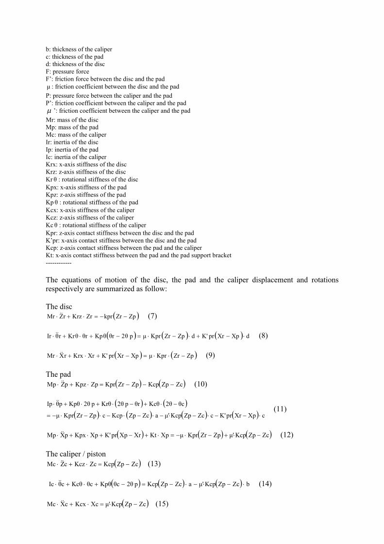
Mr: mass of the discMp: mass of the padMc: mass of the caliperIr: inertia of the discIp: inertia of the padIc: inertia of the caliperKrx: x-axis stiffness of the discKrz: z-axis stiffness of the discKr θ : rotational stiffness of the discKpx: x-axis stiffness of the padKpz: z-axis stiffness of the padKp θ : rotational stiffness of the padKcx: x-axis stiffness of the caliperKcz: z-axis stiffness of the caliperKc θ : rotational stiffness of the caliperKpr: z-axis contact stiffness between the disc and the padK’pr: x-axis contact stiffness between the disc and the padKcp: z-axis contact stiffness between the pad and the caliperKt: x-axis contact stiffness between the pad and the pad support bracket------------
The equations of motion of the disc, the pad and the caliper displacement and rotationsrespectively are summarized as follow:
The disc ZpZrkprZrKrzrZMr (7)
dXpXrprK'dZpZrKprμp 2θθrKpθθrKrθrθIr (8)
ZpZrKprμXpXrprK'XrKrxrXMr (9)
The pad ZcZpKcpZpZrKprZpKpzpZMp (10)
cXpXrprK'cZcZpKcpμ'aZcZpKcpcZpZrKprμ
θc2θKcθθrp 2θKrθp 2θKpθpθIp
(11)
ZcZpKcpμ'ZpZrKprμXpKtXrXpprK'XpKpxpXMp (12)
The caliper / piston ZcZpKcpZcKczcZMc (13)
bZcZpKcpμ'aZcZpKcpp 2θθcKpθθcKcθcθIc (14)
ZcZpKcpμ'XcKcxcXMc (15)
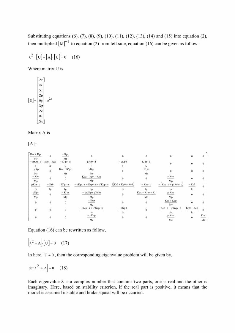
Substituting equations (6), (7), (8), (9), (10), (11), (12), (13), (14) and (15) into equation (2),
then multiplied 1M
to equation (2) from left side, equation (16) can be given as follow:
0UAU2
λ (16)
Where matrix U is
λte
Xc
θc
Zc
Xp
θp
Zp
Xr
θr
Zr
U
Matrix A is
[A]=
Mc
Kcx0
Mc
Kcpμ'00
Mc
μKcp000
0Ic
KcθKpθ
Ic
bKcpμ'aKcp0
Ic
2Kpθ
Ic
bKcpμ'aKcp000
00Mc
KcpKcz00
Mc
Kcp000
00Mp
Kcpμ'
Mp
KtprK'Kpx0
Mp
μKcp)(μμKp
Mp
prK'0
Mp
μKpr
0Ip
Kcθ
Ip
cKcpμ'aKcp
Ip
cKpr
Ip
KcθKpθKrθ2
Ip
cKcpμ'aKcpcμKpr
Ip
cprK'
Ip
Krθ
Ip
cμKpr
00Mp
Kcp00
Mp
KcpKprKpz00
Mp
Kpr
000Mr
prK'0
Mr
μKpr
Mr
prK'Krx0
Mr
μKpr
000Ir
dprK'
Ir
2Kpθ
Ir
dμKpr
Ir
dprK'
Ir
KpθKrθ
Ir
dμKpr
000000Mr
Kpr0
Mr
KprKrz
Equation (16) can be rewritten as follow,
0UA2λ (17)
In here, 0U , then the corresponding eigenvalue problem will be given by,
0A2
λdet (18)
Each eigenvalue λ is a complex number that contains two parts, one is real and the other is imaginary. Here, based on stability criterion, if the real part is positive, it means that themodel is assumed instable and brake squeal will be occurred.
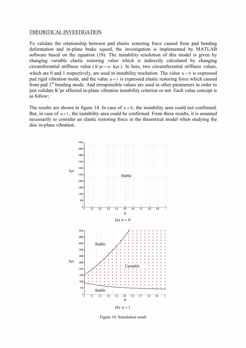
THEORITICAL INVESTIGATION
To validate the relationship between pad elastic restoring force caused from pad bendingdeformation and in-plane brake squeal, the investigation is implemented by MATLABsoftware based on the equation (18). The instability resolution of this model is given bychanging variable elastic restoring value which is indirectly calculated by changingcircumferential stiffness value ( KprαprK' ). In here, two circumferential stiffness values,
which are 0 and 1 respectively, are used in instability resolution. The value 0α is expressedpad rigid vibration mode, and the value 1α is expressed elastic restoring force which causedfrom pad 1st bending mode. And irresponsible values are used in other parameters in order tojust validate K’pr affected in-plane vibration instability criterion or not. Each value concept isas follow;
The results are shown in figure 14. In case of 0α , the instability area could not confirmed.But, in case of 1α , the instability area could be confirmed. From these results, it is assumednecessarily to consider an elastic restoring force in the theoretical model when studying thedisc in-plane vibration.
(a) 0α
μ
Kpr
Stable
Stable
(b)
Figure 14: S
Kpr
Stable
Unstable
α
im
1
ulation result
μ
EXPERIMENTAL INVESTIGATION
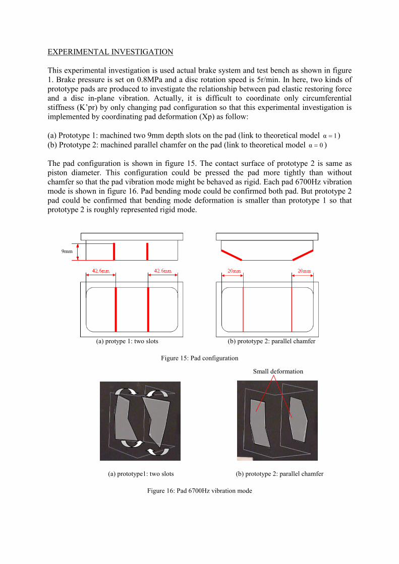
This experimental investigation is used actual brake system and test bench as shown in figure1. Brake pressure is set on 0.8MPa and a disc rotation speed is 5r/min. In here, two kinds ofprototype pads are produced to investigate the relationship between pad elastic restoring forceand a disc in-plane vibration. Actually, it is difficult to coordinate only circumferentialstiffness (K’pr) by only changing pad configuration so that this experimental investigation isimplemented by coordinating pad deformation (Xp) as follow:
(a) Prototype 1: machined two 9mm depth slots on the pad (link to theoretical model 1α )(b) Prototype 2: machined parallel chamfer on the pad (link to theoretical model 0α )
The pad configuration is shown in figure 15. The contact surface of prototype 2 is same aspiston diameter. This configuration could be pressed the pad more tightly than withoutchamfer so that the pad vibration mode might be behaved as rigid. Each pad 6700Hz vibrationmode is shown in figure 16. Pad bending mode could be confirmed both pad. But prototype 2pad could be confirmed that bending mode deformation is smaller than prototype 1 so thatprototype 2 is roughly represented rigid mode.
(a) protype 1: two slots (b) prototype 2: parallel chamfer
Figure 15: Pad configuration
(a) prototype1: two slots (b) pr
Figure 16: Pad 6700Hz vibration mode
9mm
ototype 2: parallel chamfer
Small deformation
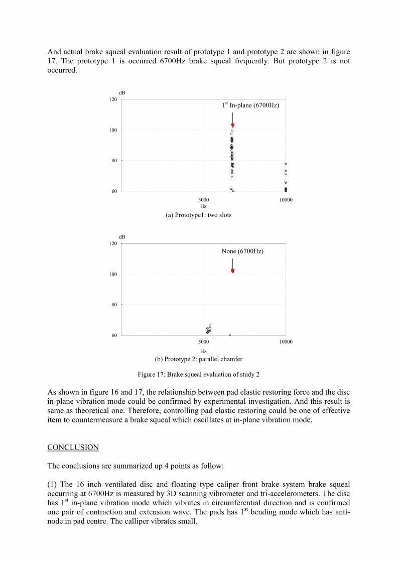
And actual brake squeal evaluation result of prototype 1 and prototype 2 are shown in figure17. The prototype 1 is occurred 6700Hz brake squeal frequently. But prototype 2 is notoccurred.
60
80
100
120
(a) Prototy
60
80
100
120
(b) Prototype 2
Figure 17: Brake sque
As shown in figure 16 and 17, the relationshipin-plane vibration mode could be confirmed bsame as theoretical one. Therefore, controllinitem to countermeasure a brake squeal which o
CONCLUSION
The conclusions are summarized up 4 points a
(1) The 16 inch ventilated disc and floatingoccurring at 6700Hz is measured by 3D scannhas 1st in-plane vibration mode which vibrateone pair of contraction and extension wave.node in pad centre. The calliper vibrates small
dB
1st In-plane (6700Hz)
dB
pe1: two slots
: parallel chamfer
al evaluation of study 2
between pad elastic restoy experimental investiga
g pad elastic restoring coscillates at in-plane vibra
s follow:
type caliper front brakeing vibrometer and tri-acs in circumferential dire
The pads has 1st bending.
5000Hz
5000
Hz
None (6700Hz)
10000
10000
ring force and the disction. And this result isuld be one of effectivetion mode.
system brake squealcelerometers. The discction and is confirmedmode which has anti-
(2) By continuing transmission of friction force and pressure variation force between disccircumferential deformation and pad bending, self-excited oscillation is generated and thebrake system 6700Hz brake squeal was occurred 1st in-plane vibration mode.
(3) Simplified theoretical model can be composed and pad elastic restoring force is assumedto include in the model when studying a disc in-plane vibration.
(4) Controlling pad elastic restoring by changing pad configuration is the one of effective itemto reduce brake squeal which oscillates in in-plane vibration mode.
REFERENCES
(1) N.Millner, An analysis of Disc Brake squeal, SAE 780332(2) Masaaki Nishiwaki, “Study on Disc Brake Squeal”, SAE Paper No.890864(3) Noriyuki Ishihara and Masaaki Nishiwaki , “Experimental Analysis of Low-FrequencyBrake Squeal Noise”, SAE paper 1996 No962128(4) Toru Matsushima, “Optimal Design Considering Robustness to Reduce Brake Squeal inDisc Brake System”, 9th World Congress on Structural and Multidisciplinary Optimization(5) Kenneth A. Cunefare, Ryan Rye, “Investigation of Disc Brake Squeal via Sound Intensityand Laser Vibrometry”, SAE Paper No.2001-01-1604(6) G. D. Liles, “Analysis of Disk Brake Squeal Using Finite Element Methods”, SAE,891150(7) Yoshitomo Denou and Masaaki Nishiwaki , “First Order Analysis of Low Frequency DiskBrake Squeal”, SAE technical Paper 2001-01-3136(8) T. Matsushima, M. Nishiwaki, H. Masumo and S. Itou, “FEM Analysis of Low-FrequencyDisc Brake Squeal (In Case of Opposed Type Caliper)”, SAE Technical Paper 973020, 1997(9) Haruhisa Baba and Takahisa Wada, “Study on Reduction of Brake squeal Caused by In-plane Vibration on Rotor”, SAE paper 2001-01-3158(10) Mihai Dupac and Chandi Biswas, “A study of Noise Reduction by Damping LayerMaterial”, SAE paper 2007-01-3954(11) Christopher Griffen and Juergen Weick, “Development of Cold Noise Brake InsulatorSolutions”, SAE paper 2009-01-3035(12) Thomas E.Reinhart and Thomas J.Wahl, “Reducing Compression Brake Noise”, SAEpaper 1997-971870(13) Chris Talbot and John D.Fieldhouse, “Investigations of In-Plane Disc Vibration UsingLaser Holography”, SAE paper 2002-01-2607(14) Michael Yang, “A study of Disc Brake High Frequency Squeal and Disc In-Plane/Out-of –Plane Modes”, SAE paper 2003-01-1621(15) Sang-Don Joo,Ji-Hoon Han,Jeong-Tae Kim and Kyung-Hwan Park, High FrequencyBrake Squeal Prediction Index for Disc In-plane Mode ,SAE paper 2009-01-2102(16) Tomohiro Yokoyama, Toru Matsushima, Noriyoshi Matsui and Ryutaro Misumi, “AStudy of Reduction for Brake Squeal in Disc In-Plane Mode”, SAE paper 2012-01-1825
ACKNOWLEDGEMENT
The author would like to thank co-author for his assistance in this work, and Mr. Yamamotoand Mr. Aiyoshizawa for their dedicated support in experimental investigation.