a dynamic fault tolerance model for microservices architecture
TRANSCRIPT

South Dakota State University South Dakota State University
Open PRAIRIE: Open Public Research Access Institutional Open PRAIRIE: Open Public Research Access Institutional
Repository and Information Exchange Repository and Information Exchange
Electronic Theses and Dissertations
2019
A Dynamic Fault Tolerance Model for Microservices Architecture A Dynamic Fault Tolerance Model for Microservices Architecture
Hajar Hameed Addeen South Dakota State University
Follow this and additional works at: https://openprairie.sdstate.edu/etd
Part of the Systems Architecture Commons
Recommended Citation Recommended Citation Addeen, Hajar Hameed, "A Dynamic Fault Tolerance Model for Microservices Architecture" (2019). Electronic Theses and Dissertations. 3410. https://openprairie.sdstate.edu/etd/3410
This Thesis - Open Access is brought to you for free and open access by Open PRAIRIE: Open Public Research Access Institutional Repository and Information Exchange. It has been accepted for inclusion in Electronic Theses and Dissertations by an authorized administrator of Open PRAIRIE: Open Public Research Access Institutional Repository and Information Exchange. For more information, please contact [email protected].
A DYNAMIC FAULT TOLERANCE MODEL FOR MICROSERVICES
ARCHITECTURE
BY
HAJAR HAMEED ADDEEN
A thesis submitted in partial fulfillment of the requirements for the
Master of Science
Major in Computer Science
South Dakota State University
2019


iii
ACKNOWLEDGEMENTS
I sincerely return all glory to Almighty God for making this thesis a reality
despite the rough and rocky journey. I deeply appreciate God for all his direction,
comfort, and strength that enabled me to continue my education.
My genuine appreciation is directed to my supervisor Dr. Yi Liu for her
moral support, supervision, guidance, motivation, understanding and patience all
along.
Also, I appreciate the entire committee members Dr. Shin and Dr. Won for
their support, constructive comments, and review, all of which led to the successful
completion of this thesis.
My profound gratitude also goes to my parents to support me all through the
program. Also, I am very thankful for my husband Emad for all his efforts and
encouragement.
Finally, I am thankful to my children Fatima, Mohsen, and Hussein for their
love and having them as a great motivation in my life.
iv
CONTENTS
LIST OF TABLES ............................................................................................................. vi
LIST OF FIGURES .......................................................................................................... vii
ABSTRACT ....................................................................................................................... ix
Chapter 1 Introduction ........................................................................................................ 1
1.1 Introduction .......................................................................................................... 1
1.2 Objectives ............................................................................................................. 2
1.3 Thesis Organization.............................................................................................. 3
Chapter 2 Background ........................................................................................................ 4
2.1 Microservices ....................................................................................................... 4
2.2 Issues of Microservices ........................................................................................ 6
2.3 Fault tolerance ...................................................................................................... 7
2.4 Stability Patterns .................................................................................................. 9
2.4.1 Timeout ......................................................................................................... 9
2.4.2 Circuit Breaker ............................................................................................ 10
2.4.3 Retry Pattern ............................................................................................... 12
2.4.4 Cache........................................................................................................... 13
2.5 Markov – Chain .................................................................................................. 14
2.6 Related Works .................................................................................................... 16
Chapter 3 DFTM Model ................................................................................................... 18
3.1 Microservice Failures ......................................................................................... 18
3.2 Dynamic Fault Tolerance (DFTM) Model Methodology .................................. 19
3.3 Implementation................................................................................................... 23
3.3.1 Markov Chain ............................................................................................. 23
3.3.2 Switch Circuit Breaker ................................................................................ 32
Chapter 4 Case Study ........................................................................................................ 35
4.1 Overview of Pet Clinic Microservices ............................................................... 35
4.2 Applying DFTM Model Methodology ............................................................... 36
Chapter 5 Evaluation......................................................................................................... 40
5.1 Reliability ........................................................................................................... 40
5.2 Performance ....................................................................................................... 41

v
Chapter 6 Conclusion ........................................................................................................ 43
6.1 Conclusion .......................................................................................................... 43
6.2 Future work ........................................................................................................ 44
6.2.1 Consider determining types of faults .......................................................... 44
6.2.2 Consider catching a failed response ............................................................ 44
REFERENCES ................................................................................................................. 45
vi
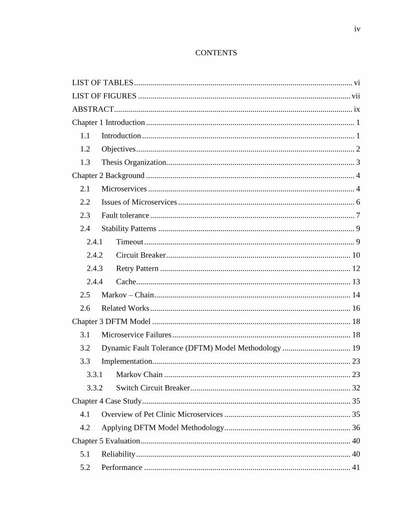
LIST OF TABLES
Table 1: Stable State Probability Matrix ........................................................................... 25
Table 2: Unstable State Probability Matrix ...................................................................... 25
Table 3: Disable State Probability Matrix ........................................................................ 25
Table 4: Test Cases Description ....................................................................................... 39
Table 5: Reliability Execution Time Comparison ............................................................ 40
Table 6: Performance Execution Time Comparison ......................................................... 41
vii
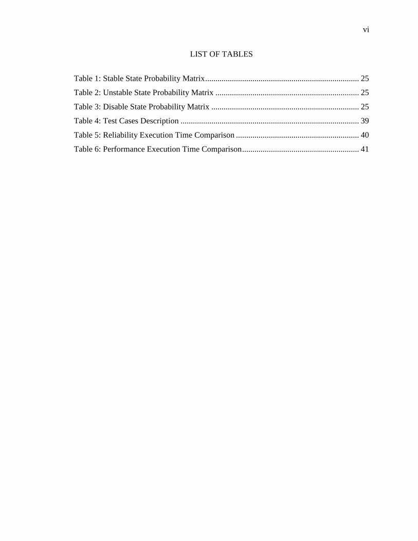
LIST OF FIGURES
Figure 1: Microservices Architecture [13] .......................................................................... 4
Figure 2: Cascading failures in Microservices Architecture [17] ....................................... 8
Figure 3: Timeout for Availability and Responsiveness [4] ............................................. 10
Figure 4: Circuit Breaker Pattern [18] .............................................................................. 12
Figure 5: Retry Mechanism [18] ....................................................................................... 13
Figure 6: Cache [20] ......................................................................................................... 14
Figure 7: Markov Chain with Two States ......................................................................... 15
Figure 8: Transition States of microservices .................................................................... 19
Figure 9: DFTM model ..................................................................................................... 21
Figure 10: Flow-chart of the DFTM model ...................................................................... 23
Figure 11: Markov Chain States for DFTM Model .......................................................... 24
Figure 12: Markov Chain UML diagram .......................................................................... 26
Figure 13: Get Response Data Function ........................................................................... 26
Figure 14: Ascending Order Code .................................................................................... 27
Figure 15: Find Frequency Function................................................................................. 27
Figure 16: Cumulative Frequency Function ..................................................................... 28
Figure 17: Find Range Function ....................................................................................... 28
Figure 18: Find Probability States Function ..................................................................... 29
Figure 19: Transition State Function ................................................................................ 29
Figure 20: Find State Count Function ............................................................................... 30
Figure 21: Find Transition Matrix Function ..................................................................... 31
Figure 22: Matrix Multiplication Function ....................................................................... 31
Figure 23: Transition Probability Function....................................................................... 31
Figure 24: Switch Circuit Breaker UML Diagram ........................................................... 32
Figure 25: Retry Code Function ....................................................................................... 33
Figure 26: ServiceExists Function .................................................................................... 34
Figure 27: Working Architecture of Pet Clinic Microservices [36] ................................. 35
Figure 28: Pet Clinic Microservice Homepage ................................................................. 36
Figure 29: Monitoring the DOWN microservice .............................................................. 37
viii
Figure 30: Test Case of Stable state in DFTM model ...................................................... 38
Figure 31: Test Case of Unstable state in DFTM model .................................................. 38
Figure 32: Test Case of Disable state in DFTM model .................................................... 38
Figure 33: Test Case Failure ............................................................................................. 38

ix
ABSTRACT
A DYNAMIC FAULT TOLERANCE MODEL FOR MICROSERVICES
ARCHITECTURE
HAJAR HAMEED ADDEEN
2019
Microservices architecture is popular for its distributive system styles due to the
independent character of each of the services in the architecture. Microservices are built
to be single and each service has its running process and interconnecting with a
lightweight mechanism that called application programming interface (API). The
interaction through microservices needs to communicate internally.
Microservices are a service that is likely to become unreachable to its consumers
because, in any distributed setup, communication will fail on occasions due to the
number of messages passing between services. Failures can occur when the networks are
unreliable, and thus the connections can be latent which may lead to failure or slow
response. This might be a problem for synchronous remote calls actively waiting for a
response. If they do not use a proper timeout mechanism, they may end up waiting for an
extended amount of time. Applications usually set a timeout for all remote calls to avoid
hanging of the whole application due to network failure or component failure. However,
this timeout needs to be set carefully to make the system or microservice application to
work as required. This would prevent further problems because if a remote call is waiting
too long for a reply, it can slow down the system in its entirety, and if a connection
timeout is extremely fast, it may ignore a response that is sent after timeout.

x
This thesis proposes a dynamic fault tolerance (DFTM) Model to improve the
stability and resilience of the microservices architecture. The Model is designed using a
two-states Circuit Breaker called Switch Circuit Breaker with Markov-Chain. In addition,
a modified Circuit Breaker (three states – open, closed, and half-open) to Switch Circuit
Breaker (two states – open and closed) is presented here. The Circuit Breaker uses
timeout to detect fault but timeouts usage hinges on assumptions about the real-time
behavior of the system and awaiting process can be deduced from the occurrence of a
timeout that a failure has occurred. Therefore, DFTM model adopted Markov Chain
based model to detect fault without a timeout. Then, it sends the fault directly to Switch
Circuit Breaker that uses a 2-states to cover the faults. An important finding is that the
DFTM model presents a solution to the problem of transient failures or faults in the inter-
service communication of microservices architecture. Also, it improves the performance
and reliability of microservices architecture.

1
Chapter 1 Introduction
1.1 Introduction
Microservices architecture is popular for its distributive system styles. It describes
a way of developing applications as suites of small services that are independently
implemented and deployed. Every service has its own running process and
interconnecting with lightweight mechanism that is called Application Programming
Interface (API) [1]. These services intend to perform a specific task around business
capabilities fully independently because each service has its own database and operations.
Microservices allow developers to use heterogenous technologies in a single
system, which increase their ability to develop the service with advancement tools. In
addition, it enhances the quality of the application. For example, if there is a problem that
occurs in a system, the developer will fix promptly due to independent characteristics. In
addition, it allows reusing the service and adds any required features at low cost [2], [3].
However, microservices have some challenges due to the distributive nature that affects
the efficiency of the architecture including availability, responsiveness, reliability, and
inter-service communication [4].
“High availability is one of the major issues of microservice-based application
design. It is difficult to build an application consisting of hardware and software that
never fail, or a more feasible strategy is to enable it fault tolerant” [7]. Microservice
system requires reliability with high availability and ensures that the whole system is not
fully impacted when there are faults in an individual service. The scheme of
microservices must be fault-tolerant [8]. However, it is unavoidable in some instances
2
that, a service in a distributed system will fail, and it will not be able to respond in an
appropriate manner leading to shutdown of the service. There are many reasons that lead
the system to failure such as heavy loads and bugs inside the code can happen [7].
As such failures are inevitable [9], they can be mitigated by developing a recovery
system in case of an error or fault or failure [8],[10]. Due to this fact, fault tolerance
emerged as one of the sub-areas of microservices architecture to ensure high stability
[11]. Fault tolerance is a way for microservices to handle the unavailability of a service
by using different stability patterns.
There are many stability patterns which have been used to achieve robustness and
resilience including Circuit Breaker Pattern, Timeout Pattern, and Retry Pattern [9], [12].
However, each of these patterns is not singly efficient enough except when it is combined
with other patterns.
1.2 Objectives
This thesis proposes a dynamic fault tolerance (DFTM) Model to improve the
stability and resilience of the microservices architecture. It provides a solution to the
problem of transient failures or faults in the inter-service communication of
microservices architecture.
The objectives of this thesis are:
1. To propose a dynamic fault tolerance model (DFTM) that detects, isolates,
and recovers communication failures in the inter-service communication
by modifying original Circuit Breaker with Markov Chain model.

3
2. To increase the reliability and performance of microservices architecture
and compare the results of DFTM model with original Circuit Breaker.
1.3 Thesis Organization
This thesis proposes a novel dynamic fault tolerance model to detect failures in
microservices architecture called DFTM Model. Chapter 1 contains the introduction of
microservices architecture and objectives. Chapter 2 discusses the general overview of
Microservices architecture, fault tolerance, stability patterns, and Markov-Chain Model.
In addition, the chapter deliberates the basic literature review and related works on fault
tolerance for microservice architecture. Chapter 3 illustrates the major components of
DFTM Model and its mechanism to detect or predict faults. Moreover, it describes the
modifications made on original Circuit Breaker in order to convert it to Switch Circuit
Breaker. Chapter 4 discusses how to apply the DFTM methodology to Pet Clinic as a
case study. Chapter 5 introduces the results of DFTM model methodology and provides a
comparison of performance and reliability between the case study and the original Circuit
Breaker Pattern. Chapter 6 provides the conclusion and future work.
4
Chapter 2 Background
2.1 Microservices
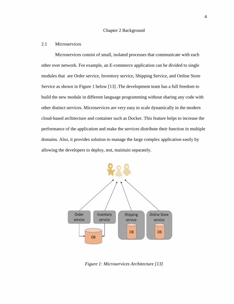
Microservices consist of small, isolated processes that communicate with each
other over network. For example, an E-commerce application can be divided to single
modules that are Order service, Inventory service, Shipping Service, and Online Store
Service as shown in Figure 1 below [13] .The development team has a full freedom to
build the new module in different language programming without sharing any code with
other distinct services. Microservices are very easy to scale dynamically in the modern
cloud-based architecture and container such as Docker. This feature helps to increase the
performance of the application and make the services distribute their function in multiple
domains. Also, it provides solution to manage the large complex application easily by
allowing the developers to deploy, test, maintain separately.
Figure 1: Microservices Architecture [13]

5
The major characteristics of microservices include the following [3]:
• Enhance fault isolation–The system continues working and is not affected in
case a failure occurs in a single microservice.
• Simply Understanding – The developers can understand the basic
functionality and their attributes faster because they act with the small
services.
• Diversity languages – It allows to write code in different programing
languages with different teams of programmer.
• Modularity – Microservices architecture is made up of isolated modules and
each of them gives the overall system performance by contributing their bits.
• Independency – In terms of operations, each of the services in microservice
architecture is self-governing and the single form of interaction between the
services is through their interfaces (API).
• Flexibility – Microservices are flexible by allowing the dynamic business
environment and readily permit all adjustments or modifications important for
the business to remain competitive.
• Deployed service – It enables developers to deploy services without needing
to understand the whole code of application. In addition, it is easily deployed
with open sources tools.
• Efficiency – It works very efficiently with multiple servers such as cloud.
• Evolution – It evolves by adding new features and ensuring maintainability.
6
2.2 Issues of Microservices
Microservices architecture has several challenges that need to be addressed as
explained below:
• Inter-Service Communication: Microservices are built to be single
independently. They communicate with each other to make a complete
system. There are protocols that are commonly used to achieve the connection
between all services inside the application. The protocols include HTTP
request by API channel that has one entry single point and Asynchronous
messaging such as AMQP. The implementation of the actual services is less
irksome than the difficulty of communication. As discussed earlier, using API
that contains smart endpoints and dumb pipes will encourage to have inter-
service communication logic as part of the microservices. Also, each service
has its own database and that leads to multiple databases and transaction data.
All these databases need more efforts to monitor particularly in growing
applications [4]. The goal for each microservice in the infrastructure is to be
available to the client, even if the other services might be unhealthy or
unavailable. However, susceptibilities are high due to the high dispersal and
network complexity. This also poses additional difficulty in debugging,
auditing, and forensic [3], [16].
• Process Availability and Responsiveness: Distributed system has many issues,
one of which is handling isolated process availability and responsiveness.
Service availability means the service was connected and able to send a
7
request while service responsiveness is the time taken for the service to
respond to the request [4]. Service availability and responsiveness are closely
related to service communication.
• Reliability: It refers to a system that can perform the functions well without
halting, according to its requirements, and it is fault tolerant. Reliability is
particularly challenging for distributed microservices, threatened by
integration and message passing mechanisms [5].
2.3 Fault tolerance
Microservice-based system design includes many sub-areas that are partially
related to Integration, Fault Tolerance, Service Discovery, Versioning, and Scalability
and Security [11]. Integration involves making the system seem like a single system to
the end users by ensuring proper communication between the User Interface (UI), Data
Management and intercommunication of the microservices via Application Programming
Interface (API). Service Discovery locates currently running instances. Scalability entails
load balancing and caching. Fault tolerance ensures no failure or unavailability of
microservices while communicating with each other to fulfill their activities. However,
microservices are loosely coupled and communicate over the network. In some cases,
when one of the services becomes unavailable, it affects the whole system and causes
cascading failures [17]. For example, calling of service takes a long time or the service is
not up as shown in Figure 2:

8
Figure 2: Cascading failures in Microservices Architecture [17]
Microservices are susceptible to faults/failures due to the propagation of the
services and their inter-services depending on the network for communications. A
microservice application is an assemblage of fine-grained services, thus, a partial failure
or fault in one or more of those services should not bring down the entire application. In
order to protect the full service from failure, there is a need to apply stability patterns or
resiliency-related abilities, such as circuit breakers, disaster recovery, load-balancing,
fail-over, and dynamic scaling based on traffic patterns [9].
Failures or faults can occur because the networks are unreliable, and the
connections can be latent, which may result in failure or slow response. This might be a
problem for synchronous remote calls actively waiting for a response. Therefore, it was
concluded that fault tolerance mechanisms are required to prevent prompt faults of a
service or of the network from halting the system. If there is no stability design
mechanism, the microservices might end up keeping user or other microservices waiting
for a long time.
9
Handling errors and restarting service are one of the hardest problems to solve in
microservices architectures. It is important to build microservices with a high availability
and resiliency to avoid unexpected failures. Fault tolerance is a way for microservices to
handle the unavailability of a service by using different policies such as Circuit Breaker,
fallback, and timeout [2], [4].
2.4 Stability Patterns
A system is said to be stable when it keeps handling transactions, even when there
are short-lived itches or failures of constituent components upsetting normal processing
[18].
There are total of eight healthy stability design patterns to decrease, remove, or
alleviate the effects of failures in the system such as Timeout, Circuit Breaker, and Retry
Pattern [4].
2.4.1 Timeout
Timeout is a particularly critical method in distributed data structures. Timeout is
a simple pattern that disallows a continual wait for a response from a service. It is used to
determine service availability and responsiveness while preventing slow responses as
shown in figure 3. It works with the Circuit Breaker and retry mechanism to determine
the entire time of service to perform the task. Each service should implement own
operation in limited time. For example, the service will respond in 1 second. If the service
exceeds the determined time, it will call fallback mechanism to handle request. The
fallback mechanism works as an alternative way for covering the non – responding
service such as cache service.

10
Timeout is very important to control the time of service response, otherwise the
consumer will wait for a long period of time to implement his or her service. Timeout can
prevent hanging operations and keep the system responsive [4].
However, using static, fine-tuned timeout in microservices communication are an
anti-pattern as the architecture is a highly dynamic environment where it is almost
impossible to come up with the right timing limitations that work well in every case.
Figure 3: Timeout for Availability and Responsiveness [4]
2.4.2 Circuit Breaker
This pattern works just like a circuit breaker in a residential house. Electric
current flows through the electronic systems once the circuit breaker is flipped on (closed
circuit) and stops the flow immediately it is off (opened circuit). Also, the software
circuit breaker pattern allows communication when it is closed and hinders it when it is
opened [4].
Remote calls of the services are continuously monitored by the circuit breaker.
While the ongoing service is available, the circuit breaker will be closed. Consequently,
the client’s requests are served. It is possible that, if the service is not available, the
circuit breaker opens to isolate the faults until it is available.
11
Circuit breakers protect against integration points, cascading failures, unbalanced
capacities, and slow responses. This pattern along with timeouts averts imminent
cascading failures. It also aids capacity maintenance when the system is under stress
because of partial failures. In case of weakness due to faults, Circuit Breaker Pattern
detects faults and fixes them by using fail fast directly. Also, the client will not know
about the problem because the server will prevent calling function until the problem is
fixed. In addition, the cost of failure can be dropped to the lowest level because the
process of detecting errors was done at an early stage.
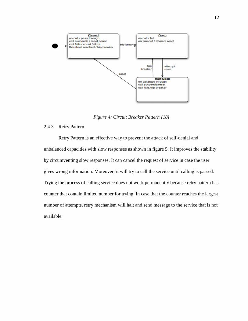
As illustrated in figure 4, Circuit Breaker Pattern has three (3) states, that are
closed state, open state and half-open. In the “closed” state, the circuit breaker performs
processes as normal. If the call does not fail, the circuit remains closed. However, if it
fails and the number of failures exceeds a threshold, the circuit breaker trips will “open”
the circuit. After counting a specific amount of time, the circuit breaker goes into the
“half-open” state to check the possibility of the success of the service. Sometimes, the
failure does not have relation to the function operations, but it is occurred by latency in
the network. In case that calling the service in half-state by retry mechanism is
successful, the circuit breaker changes to the “closed” state. In addition, it returns to the
“open” state if the calling service is failed until another timeout is in place. It will repeat
this trip multiple times until the problem is solved. However, there exists an unnecessary
consumption of resources by calling through half-state open repeatedly.
12
Figure 4: Circuit Breaker Pattern [18]
2.4.3 Retry Pattern
Retry Pattern is an effective way to prevent the attack of self-denial and
unbalanced capacities with slow responses as shown in figure 5. It improves the stability
by circumventing slow responses. It can cancel the request of service in case the user
gives wrong information. Moreover, it will try to call the service until calling is passed.
Trying the process of calling service does not work permanently because retry pattern has
counter that contain limited number for trying. In case that the counter reaches the largest
number of attempts, retry mechanism will halt and send message to the service that is not
available.

13
Figure 5: Retry Mechanism [18]
However, responsiveness of an application might be affected due to a fault, which
might take a longer time; therefore, retry pattern might not be useful. The application will
waste time and resources will be consumed unnecessarily to repeat calling a request that
is likely to fail [18].
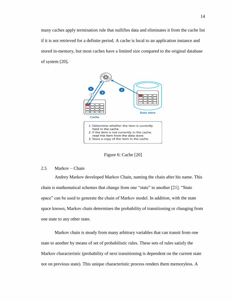
2.4.4 Cache
Cache mechanism improves the performance of an application by getting data
from cache service rather than calling the database every time to get the same data as
shown in figure 6. The mechanism is useful with a body of static data that does not
change continuously. However, the cache service must refresh data to avoid inconsistent
data problems with data in the database. The application should contain a technique to
update the data in the cache to be as up to date as possible. In addition, it can detect data
when it has stale situations and notify the database to avoid stale data. The way of
refreshing data in caching will depend on the design of application. Refreshing data can
happen in the beginning of application or after updating the special services. Moreover,
14
many caches apply termination rule that nullifies data and eliminates it from the cache list
if it is not retrieved for a definite period. A cache is local to an application instance and
stored in-memory, but most caches have a limited size compared to the original database
of system [20].
Figure 6: Cache [20]
2.5 Markov – Chain
Andrey Markov developed Markov Chain, naming the chain after his name. This
chain is mathematical schemes that change from one “state” to another [21]. “State
space” can be used to generate the chain of Markov model. In addition, with the state
space known, Markov chain determines the probability of transitioning or changing from
one state to any other state.
Markov chain is steady from many arbitrary variables that can transit from one
state to another by means of set of probabilistic rules. These sets of rules satisfy the
Markov characteristic (probability of next transitioning is dependent on the current state
not on previous state). This unique characteristic process renders them memoryless. A

15
Markov chain contains a random process with the Markov characteristics. For instance,
Markov chain consists of a series of random elements X1, X2 that guarantee Markov
property, such that the probability of transiting to the next state is influenced by the
present state and not the previous states. “The probabilistic formula [22]:
Pr (Xn+1 = x | X1 = x1, X2 = x2, …, Xn = xn) = Pr (Xn+1 = x | Xn = xn)
The probabilities produce with movement of state and are called transition
probabilities. Calculation process must compute the transition matrix whose entries in
each row must add up to exactly 1 because each row represents its own probability
distribution” [22].
Figure 7 below shows an example for Markov chain with 2-states, which can
produce four chances to generate different probabilities of states. The four chances are
AA, AB, BB, and BA.
Figure 7: Markov Chain with Two States
As mentioned previously, Markov Chain essentially involves a set of transitions
determined by probability distribution that satisfies the Markov property. This probability
distribution is computed solely by detecting transitions from the current state to the next.
Thus, are demonstrating the Markov property, which forms the unique feature of Markov
procedures that renders them memoryless [23].
16
2.6 Related Works
Haselbock et.al in [24] presented the creation and validation of a decision
guidance metamodel, and of the specific decision guidance models for the different areas
of microservice system design. It presented fault tolerant guidance models without any
implementation.
Circuit breaker, discovery, and API gateways were discussed by Montesi &
Weber in [2]. Circuit breaker was discussed as a solution to the problem of
communications among microservices through message passing, which causes
communication failures, and timeouts among components and congestion of service.
Toffetti et.al proposed an architecture that leverages on the concepts of service
orchestration and distributed configuration management with consensus algorithms to
enable self-management of cloud-based microservices [25].
A methodology for reliability and fault-tolerance by Choreographic Design of
distributed applications was proposed by Cassar in [26]. They integrated the run-time
monitoring and local adaptation of distributed components with the top-down
decomposition approach brought about by choreographic development.
Tang et.al presented the design of high availability service discovery for
microservices architecture by improving RAFT consensus algorithm. However, the
leader takes absolute dominance of the whole process, if the leader is not saved, the
system can be controlled maliciously [28].
A Self-Healing Microservices Architecture with Docker as a case study was
published in [29]. It offers continuous monitoring and detection of anomalous behavior

17
and provides the architecture with dynamic decision-making based on the employment of
the multidimensional utility-based model.
Hystrix library as developed by Preuveneers et.al controls the networks
connection between distributed services by including two types of tolerance logic;
latency and fault. This library utilizes Bulkhead, Swim Lane, and Circuit Breaker patterns
as isolation techniques to reduce the influence of any service that is dependent on another
service. Moreover, it shields against failures not only in the network traffic [30] but also
in the whole dependency client performance. However, the three states of Circuit Breaker
Pattern, that are open state, closed state, half-open state can lead to overhead cost. Circuit
Breaker Pattern will detect fault and open state to call the service with computing a
specific time. If the call fails, half-open state will try calling again and compute another
limited time. However, DFTM model detects faults with Markov Chain based model
without computing timeout. Then, it sends the faults directly to Switch Circuit Breaker
that uses a 2-state to cover the faults. There is no need to have the third state to repeat the
calling of service, so, DFTM model removed the half-open state and exchanged it by
adding Markov Chain based model.
18
Chapter 3 DFTM Model
Microservices are designed to run in a highly distributed environment. This
environment brings not only several benefits but also brings challenges in terms of
failures or faults due to the network communication of the services. Therefore, this poses
a need to address the failures to software architect/designers [32]. Several Stability
Patterns (Timeout, Circuit Breaker, Retry Pattern) as mentioned in chapter 2 have been
created to minimize the impact of failures in distributed systems such as microservices.
3.1 Microservice Failures
Failures can occur when the networks are unreliable or the connections are latent,
which might lead to failure or slow response. This might be a problem for synchronous
remote calls actively waiting for a response. If they do not use any timeout mechanism,
they may end up waiting for a long period of time. Applications usually set a timeout for
all remote calls to avoid hanging of the entire application due to network failure or a
component failure. However, this timeout needs to be set carefully to make the system or
microservice application work as required. This would prevent further problems because
if a remote call is waiting too long for a reply, it can slow down the whole system.
Similarly, if a connection timeout is excessively fast, it may ignore a response that is sent
after timeout [33]. Meanwhile, Circuit Breaker depends on the timeout to determine the
switching or tripping from one state to another. Therefore, there is need for Switch
Circuit Breaker using Markov Chain.
As stated previously, microservice application is an assemblage of fine-grained
services, thus, a failure or fault in one or more of those services should not bring down
the entire application. Therefore, a given failure of microservices should be handled
19
properly so that a failure has minimum effects on the functionalities of the application.
The other feature of failure tolerance is the ability to detect the behavior of the
microservices running. Identifying or forecasting or predicting failures in a service and
reinstating such services are important [9].
3.2 Dynamic Fault Tolerance (DFTM) Model Methodology
This research proposes a dynamic fault tolerance (DFTM) Model using a two-
states Circuit Breaker called Switch Circuit Breaker with Markov Chain. This research
modified Circuit Breaker (three states – open, closed and half-open) to Switch Circuit
Breaker (two states – open and closed). The Circuit Breaker uses timeout to detect fault
[2], but timeouts usage hinges on assumptions about the real-time behavior of the system,
and a waiting process can be deduced from the occurrence of a timeout that a failure has
occurred [27]. Therefore, we adopted Markov Chain based model to detect fault without
timeout.
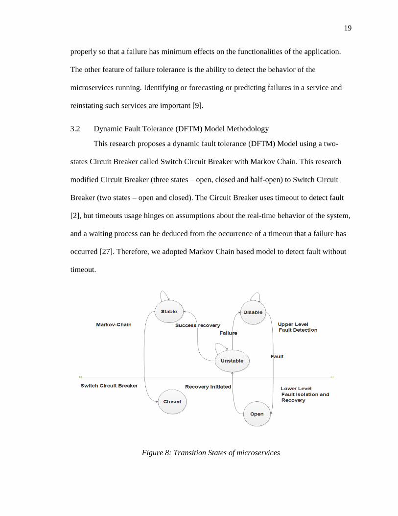
Figure 8: Transition States of microservices

20
Figure 8 shows the Transition States of microservices. There are two basic levels: Upper
level - Fault detection / Discovery level and Lower level- Fault Isolation and Recovery.
The Upper level that includes Markov Chain is used to drive the lower level while the
lower level that includes the Switch Circuit Breaker is used to drive the availability of the
microservice.
Upper level – this level detects faults or attempt to discover fault. It is based on the
Markov Chain model. This level consists of three (3) states:
1. Stable state – at this state, the microservice is available for the client with no fault.
2. Unstable state – the microservice has either detected fault or attempted to repair.
3. Disable state – the microservice has failed after trial and it is now unavailable.
Lower level – this level is also called the fault isolation level and Recovery level. It
isolates the fault microservice by employing a switch circuit breaker. It has two (2) states:
1. Closed state – the Switch Circuit Breaker is closed when the microservice is
available for operations, that is, the microservice is in a stable state. Therefore,
circuit grants user requests.
2. Open state – the Switch Circuit Breaker is opened when their fault, and it allows
automatic repair.

21
Figure 9: DFTM model
Figure 9 shows the overall DFTM model with highlighted components and
mechanisms of the model with their interactions. The main components include Clients,
Switch Circuit Breaker, Markov Chain Model, Retry mechanism, Cache and
Microservices. The Client sends request(s) that passes through the Switch Circuit Breaker
or inter-microservices communication. The Switch Circuit Breaker controls the
communication of the microservices by getting the predetermined/predicted state of the
microservices through Markov Chain. The Switch Breaker will close if Markov Chain
returns to “Stable State”, and it will open if Markov Chain returns to “Unstable State” or
“Disable State”. The Switch Circuit Breaker sends to retry pattern in case of an error.
Retry patterns enables an application to handle momentary or transient failures (including
the momentary loss of network connectivity to components and services, the temporary
22
unavailability of a service) when it tries to connect to a service or network resource by
transparently retrying a failed operation. This helps to increase the stability of the
application. Markov Chain sends to Cache if the state is not favorable for the successful
running of the microservices.
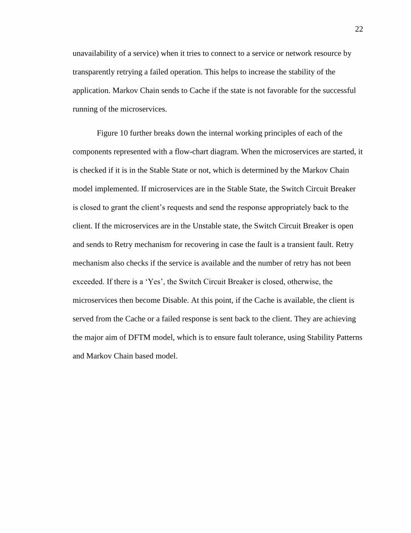
Figure 10 further breaks down the internal working principles of each of the
components represented with a flow-chart diagram. When the microservices are started, it
is checked if it is in the Stable State or not, which is determined by the Markov Chain
model implemented. If microservices are in the Stable State, the Switch Circuit Breaker
is closed to grant the client’s requests and send the response appropriately back to the
client. If the microservices are in the Unstable state, the Switch Circuit Breaker is open
and sends to Retry mechanism for recovering in case the fault is a transient fault. Retry
mechanism also checks if the service is available and the number of retry has not been
exceeded. If there is a ‘Yes’, the Switch Circuit Breaker is closed, otherwise, the
microservices then become Disable. At this point, if the Cache is available, the client is
served from the Cache or a failed response is sent back to the client. They are achieving
the major aim of DFTM model, which is to ensure fault tolerance, using Stability Patterns
and Markov Chain based model.

23
Figure 10: Flow-chart of the DFTM model
3.3 Implementation
In this study, DFTM model was implemented using PHP (Laravel/Lumen framework).
Markov Chain, Switch Circuit Breaker, Retry and Cache patterns were developed using
PHP (Laravel/Lumen framework).
3.3.1 Markov Chain
This research proposes to detect faults using Markov Chain with three states
(Stable, Unstable and Disable) with Switch circuit breaker with two states (Open and
Closed) as explained previously.
In Markov Chain, a random variable Xk at the time instant k is measured, and it
can attain several sets of values (X1, X2, ... Xn). The probability that a random variable
can attain a state (xi) at a specific time instant depends on the present state at the time
24
instant according to the Markov property. The initial state of the microservices is
received from the response time of the microservices.
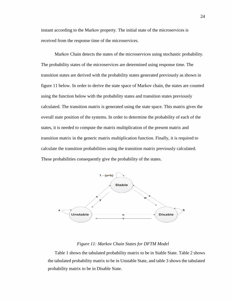
Markov Chain detects the states of the microservices using stochastic probability.
The probability states of the microservices are determined using response time. The
transition states are derived with the probability states generated previously as shown in
figure 11 below. In order to derive the state space of Markov chain, the states are counted
using the function below with the probability states and transition states previously
calculated. The transition matrix is generated using the state space. This matrix gives the
overall state position of the systems. In order to determine the probability of each of the
states, it is needed to compute the matrix multiplication of the present matrix and
transition matrix in the generic matrix multiplication function. Finally, it is required to
calculate the transition probabilities using the transition matrix previously calculated.
These probabilities consequently give the probability of the states.
Figure 11: Markov Chain States for DFTM Model
Table 1 shows the tabulated probability matrix to be in Stable State. Table 2 shows
the tabulated probability matrix to be in Unstable State, and table 3 shows the tabulated
probability matrix to be in Disable State.

25
Table 1: Stable State Probability Matrix
Stable Unstable Disable
Stable 1 0 0
Unstable 1 0 0
Disable 1 0 0
Table 2: Unstable State Probability Matrix
Stable Unstable Disable
Stable 0 1 0
Unstable 0 1 0
Disable 0 1 0
Table 3: Disable State Probability Matrix
Stable Unstable Disable
Stable 0 0 1
Unstable 0 0 1
Disable 0 0 1
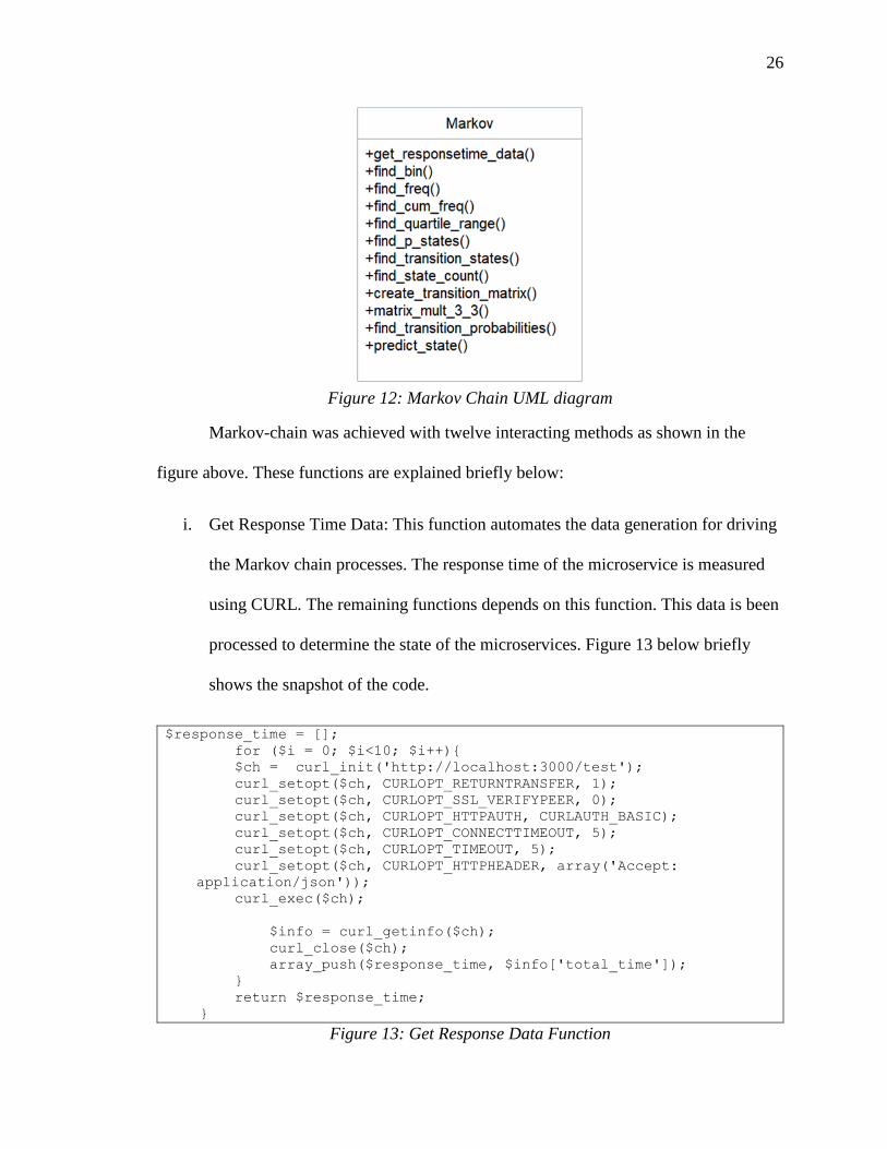
Figure 12 shows the class UML (Unified Modelling Language) of the Markov
chain class. This class – Markov has (12) methods/functions to detect the states of the
microservices.
26
Figure 12: Markov Chain UML diagram
Markov-chain was achieved with twelve interacting methods as shown in the
figure above. These functions are explained briefly below:
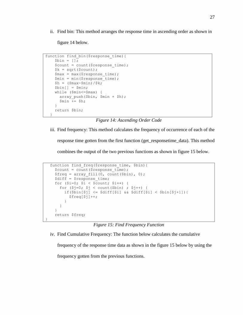
i. Get Response Time Data: This function automates the data generation for driving
the Markov chain processes. The response time of the microservice is measured
using CURL. The remaining functions depends on this function. This data is been
processed to determine the state of the microservices. Figure 13 below briefly
shows the snapshot of the code.
$response_time = [];
for ($i = 0; $i<10; $i++){
$ch = curl_init('http://localhost:3000/test');
curl_setopt($ch, CURLOPT_RETURNTRANSFER, 1);
curl_setopt($ch, CURLOPT_SSL_VERIFYPEER, 0);
curl_setopt($ch, CURLOPT_HTTPAUTH, CURLAUTH_BASIC);
curl_setopt($ch, CURLOPT_CONNECTTIMEOUT, 5);
curl_setopt($ch, CURLOPT_TIMEOUT, 5);
curl_setopt($ch, CURLOPT_HTTPHEADER, array('Accept:
application/json'));
curl_exec($ch);
$info = curl_getinfo($ch);
curl_close($ch);
array_push($response_time, $info['total_time']);
}
return $response_time;
}
Figure 13: Get Response Data Function
27
ii. Find bin: This method arranges the response time in ascending order as shown in
figure 14 below.
function find_bin($response_time){
$bin = [];
$count = count($response_time);
$k = sqrt($count);
$max = max($response_time);
$min = min($response_time);
$h = ($max-$min)/$k;
$bin[] = $min;
while ($min<=$max) {
array_push($bin, $min + $h);
$min += $h;
}
return $bin;
}
Figure 14: Ascending Order Code
iii. Find frequency: This method calculates the frequency of occurrence of each of the
response time gotten from the first function (get_responsetime_data). This method
combines the output of the two previous functions as shown in figure 15 below.
function find_freq($response_time, $bin){
$count = count($response_time);
$freq = array_fill(0, count($bin), 0);
$diff = $response_time;
for ($i=0; $i < $count; $i++) {
for ($j=0; $j < count($bin) ; $j++) {
if($bin[$j] <= $diff[$i] && $diff[$i] < $bin[$j+1]){
$freq[$j]++;
}
}
}
return $freq;
}
Figure 15: Find Frequency Function
iv. Find Cumulative Frequency: The function below calculates the cumulative
frequency of the response time data as shown in the figure 15 below by using the
frequency gotten from the previous functions.

28
function find_cum_freq($freq){
$cum_freq = array_fill(0, count($freq), 0);
for ($i=0; $i < count($freq) ; $i++) {
for ($j=0; $j <= $i; $j++) {
$cum_freq[$i] += $freq[$j];
}
}
return $cum_freq;
}
Figure 16: Cumulative Frequency Function
v. Find Quartile Range: The function below finds the quartile range of the set of the
response time by dividing the cumulative frequency calculated previously into a
group of four as seen in figure 17 below. The difference is calculated using the
bin and frequency variable over the span of the data.
function find_quartile_range($bin, $freq, $cum_freq){
$n = end($cum_freq);
$n1 = $n/4; $n2 = $n/2;
$n3 = ($n*3)/4;
$range[] = $bin[0];
for ($i=0; $i < count($cum_freq) ; $i++) {
if ($cum_freq[$i]<=$n1 && $n1<$cum_freq[$i+1]) {
$range[] = ($n1-$cum_freq[$i])<($cum_freq[$i+1]-$n1) ?
$bin[$i] : $bin[$i+1];
}
if ($cum_freq[$i]<=$n2 && $n2<$cum_freq[$i+1]) {
$range[] = ($n2-$cum_freq[$i])<($cum_freq[$i+1]-$n2) ?
$bin[$i] : $bin[$i+1];
}
if ($cum_freq[$i]<=$n3 && $n3<$cum_freq[$i+1]) {
$range[] = ($n3-$cum_freq[$i])<($cum_freq[$i+1]-$n3) ?
$bin[$i] : $bin[$i+1];
}
}
$range[]=end($bin);
return $range;
}
Figure 17: Find Range Function
vi. Find Probability State (find_p_states): The function shown in figure 18 below
calculates the probabilities of the states using the response time and the range
determined previously.

29
function find_p_states($response_time, $range){
$p_states = [];
$diff = $response_time;
foreach ($diff as $key => $value) {
if ($range[0] <= $value && $value < $range[1]) {
$p_states[$key] = "P1";
}elseif ($range[1] <= $value && $value < $range[2]) {
$p_states[$key] = "P2";
}elseif ($range[2] <= $value && $value < $range[3]) {
$p_states[$key] = "P3";
}else{
$p_states[$key] = null;
}
}
return $p_states;
}
Figure 18: Find Probability States Function
vii. Find transition states (find_transition_states): The transition state is calculated
with the probabilities generated earlier as shown in figure 19 below. This aids the
generation and computation of the transition matrix.
function find_transition_states($p_states){
$count = count($p_states)-1;
for($key=0; $key < $count; $key++) {
for ($i=1; $i <= 3; $i++) {
for ($j=1; $j <= 3 ; $j++) {
if (($p_states[$key] == "P" . $i) && ($p_states[$key+1] ==
"P" . $j) ) {
$transition_states[$key+1] = "P_" . $i . $j;
}
}
}
}
return $transition_states;
}
Figure 19: Transition State Function
viii. Find State Count: The number of the states is determined with the code in figure
20 below using the probability states and the transition states.

30
function find_state_count($p_states, $transition_states){
$state_count = array(
'P1' => 0 ,'P2' => 0 ,'P3' => 0 ,
'P_11' => 0 ,'P_12' => 0 ,'P_13' => 0 ,
'P_21' => 0 ,'P_22' => 0 ,'P_23' => 0 ,
'P_31' => 0 ,'P_32' => 0 ,'P_33' => 0
);
foreach ($p_states as $key => $value) {
if ($value == "P1") {
$state_count["P1"]++;
}elseif ($value == "P2") {
$state_count["P2"]++;
}elseif ($value == "P3") {
$state_count["P3"]++;
}
}
foreach ($transition_states as $key => $value) {
for ($i=1; $i <= 3; $i++) {
for ($j=1; $j <= 3 ; $j++) {
if ( $value == "P_" . $i . $j) {
$state_count["P_" . $i . $j]++;
}
}
}
}
return $state_count;
}
Figure 20: Find State Count Function
ix. Create Transition Matrix: Since Markov Chain is memoryless, transition matrix is
determined as shown below in figure 21 with the state count generated in the
previous function.
function create_transition_matrix($state_count){
$transition_matrix = array(
array( $state_count['P1'] == 0 ? 0 :
$state_count["P_11"]/$state_count["P1"] ,
$state_count['P1'] == 0 ? 0 :
$state_count["P_12"]/$state_count["P1"],
$state_count['P1'] == 0 ? 0 :
$state_count["P_13"]/$state_count["P1"]),
array( $state_count['P2'] == 0 ? 0 :
$state_count["P_21"]/$state_count["P2"] ,
$state_count['P2'] == 0 ? 0 :
$state_count["P_22"]/$state_count["P2"],
$state_count['P2'] == 0 ? 0 :
$state_count["P_23"]/$state_count["P2"]),
array( $state_count['P3'] == 0 ? 0 :
$state_count["P_31"]/$state_count["P3"] ,
31
$state_count['P3'] == 0 ? 0 :
$state_count["P_32"]/$state_count["P3"],
$state_count['P3'] == 0 ? 0 :
$state_count["P_33"]/$state_count["P3"])
);
return $transition_matrix;
}
Figure 21: Find Transition Matrix Function
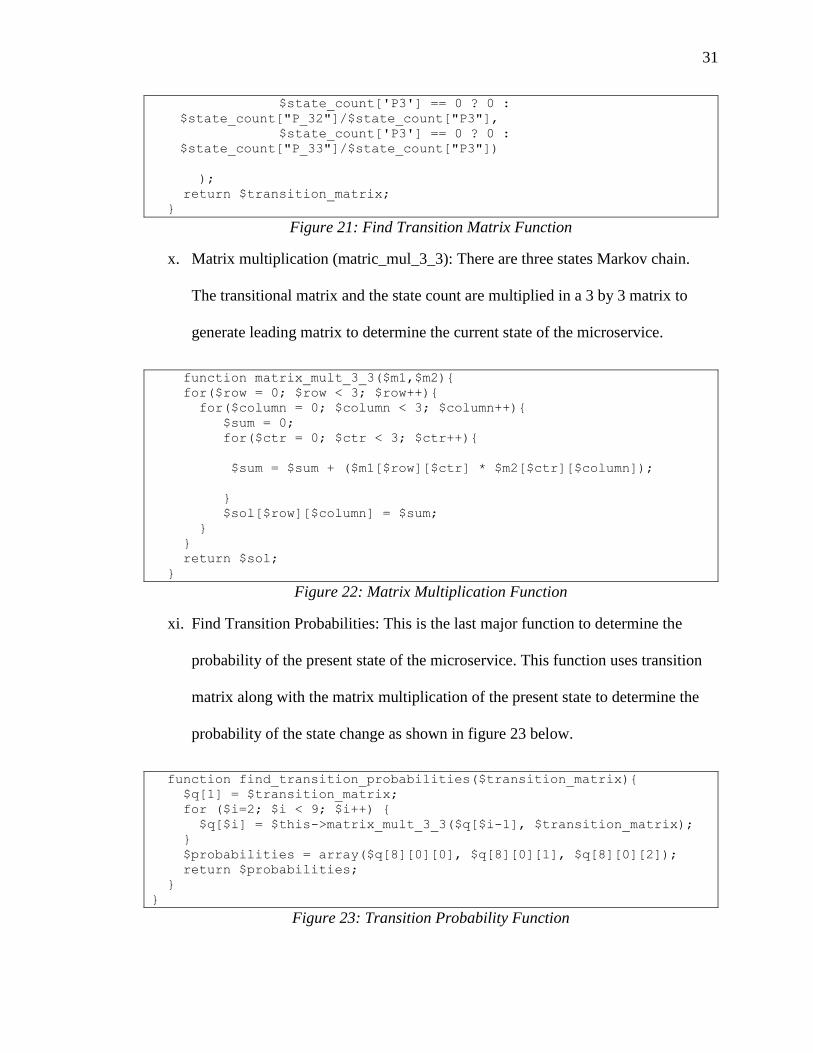
x. Matrix multiplication (matric_mul_3_3): There are three states Markov chain.
The transitional matrix and the state count are multiplied in a 3 by 3 matrix to
generate leading matrix to determine the current state of the microservice.
function matrix_mult_3_3($m1,$m2){
for($row = 0; $row < 3; $row++){
for($column = 0; $column < 3; $column++){
$sum = 0;
for($ctr = 0; $ctr < 3; $ctr++){
$sum = $sum + ($m1[$row][$ctr] * $m2[$ctr][$column]);
}
$sol[$row][$column] = $sum;
}
}
return $sol;
}
Figure 22: Matrix Multiplication Function
xi. Find Transition Probabilities: This is the last major function to determine the
probability of the present state of the microservice. This function uses transition
matrix along with the matrix multiplication of the present state to determine the
probability of the state change as shown in figure 23 below.
function find_transition_probabilities($transition_matrix){
$q[1] = $transition_matrix;
for ($i=2; $i < 9; $i++) {
$q[$i] = $this->matrix_mult_3_3($q[$i-1], $transition_matrix);
}
$probabilities = array($q[8][0][0], $q[8][0][1], $q[8][0][2]);
return $probabilities;
}
}
Figure 23: Transition Probability Function
32
xii. Predict State: This is the main matrix that calls all the methods according to their
usage. In order to determine the state of the microservices.
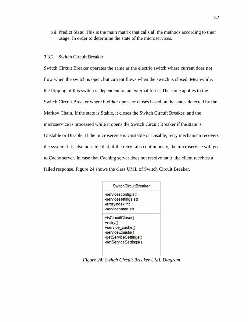
3.3.2 Switch Circuit Breaker
Switch Circuit Breaker operates the same as the electric switch where current does not
flow when the switch is open, but current flows when the switch is closed. Meanwhile,
the flipping of this switch is dependent on an external force. The same applies to the
Switch Circuit Breaker where it either opens or closes based on the states detected by the
Markov Chain. If the state is Stable, it closes the Switch Circuit Breaker, and the
microservice is processed while it opens the Switch Circuit Breaker if the state is
Unstable or Disable. If the microservice is Unstable or Disable, retry mechanism recovers
the system. It is also possible that, if the retry fails continuously, the microservice will go
to Cache server. In case that Caching server does not resolve fault, the client receives a
failed response. Figure 24 shows the class UML of Switch Circuit Breaker.
Figure 24: Switch Circuit Breaker UML Diagram

33
• IsCircuitClose:
This function checks the state of the microservices as reported from Markov
chain. If Markov returns a value that is equal to “Stable”, this function returns true
and continues execution of the microservices. Otherwise, the process sequence
will send to retry function as described below.
• Retry function:
This function gets the predicted state of the microservices from Markov chain and
sets the maximum number of retry to three (3). It checks if the state is still
unstable and the maximum number has not been exceeded. It retries the service if
it returns true but enters cache if it returns false. The system is delayed for one
second between each retry. Figure 25 below explains the code implementation as
follows:
public function retry(){
$markov = new Markov();
$state = $markov->predict_state();
$max_retries = 3;
$retry_count = 0;
while(($state == 'Unstable') && ($retry_count <
$max_retries))
{
parent::retry();
sleep(1);
$retry_count ++;
}
return true;
}
Figure 25: Retry Code Function
• Cache:
This function calls the service cache if the retry failed to get a “Stable” response
from Markov Chain. If the cache fails, the system returns a failed response.
• Settings Related Functions:
These functions include serviceExists, getServiceSettings and setServiceSettings.

34
These functions are meant to get the major settings to keep the microservices in
the correct configuration. Function serviceExists checks for the existence of the
route in the service list. GetService Settings function gets the settings of the
microservices while setServiceSettings function sets the microservices settings.
/**
* Function serviceExists
*
* Checks either service is configured in config.php or not
*
*/
private function serviceExists() {
$index = 0;
foreach ($this->servicesconfig as $config) {
//($config);
if($config['servicename']===$this->servicename) {
// Service is configured so return true
$this->arrayindex = $index;
return true;
break;
}
$index++;
}
// Service is not configured so return false
return false;
}
Figure 26: Service Exists Function

35
Chapter 4 Case Study
This chapter demonstrates how to apply the dynamic fault tolerance (DFTM)
model that is presented in chapter 3 to Pet Clinic microservices, which is a spring-boot
based microservice.
4.1 Overview of Pet Clinic Microservices
Spring Boot creates individual and production-grade Spring based applications
easily [35]. It evolves from Spring framework written in Java. It is bootstrap that is
described in the following reference: - Spring Initializer (https://start.spring.io).
Spring Pet Clinic Microservices obtained from GitHub at
https://github.com/spring-petclinic/spring-petclinic-microservices was built around small
independent running in their own JVM and communicating over HTTP via REST API.
These microservices are all written in Java. It has three (3) functional microservices:
customers, vets and, visits. The working of the internal structure of the application is
shown in figure 26:
Figure 27: Working Architecture of Pet Clinic Microservices [36]

36
As shown in figure 26, the 3 microservices – customers-service, vets-service and
visits-service expose the functionality of the application through a REST API. Each of
these 3 microservices is an application in the sense of Spring Boot with its own Maven
module containing certain Java classes and configuration files.
The API-gateway controls and coordinates the remaining services. Customers-
service microservice enables the customers to get for pets’ details, pets request and the
owners’ details. The vets-service microservice allows to receive the vet details and vets’
expertise. Visits-service microservice provides information about the pets visit and the
owner visits.
4.2 Applying DFTM Model Methodology
The microservice is started and the admin board for monitoring the UP or DOWN
service is monitored as provided by the Pet Clinic Developer. Figure 27 below shows the
homepage of the microservices when it is started.
Figure 28: Pet Clinic Microservice Homepage
37
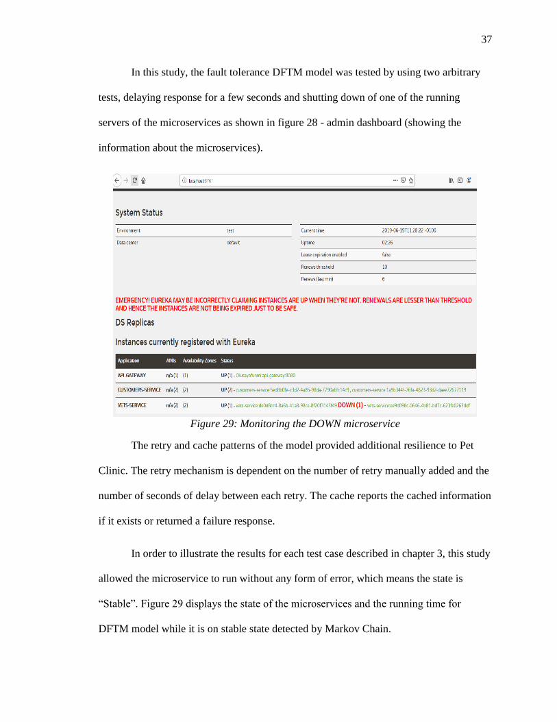
In this study, the fault tolerance DFTM model was tested by using two arbitrary
tests, delaying response for a few seconds and shutting down of one of the running
servers of the microservices as shown in figure 28 - admin dashboard (showing the
information about the microservices).
Figure 29: Monitoring the DOWN microservice
The retry and cache patterns of the model provided additional resilience to Pet
Clinic. The retry mechanism is dependent on the number of retry manually added and the
number of seconds of delay between each retry. The cache reports the cached information
if it exists or returned a failure response.
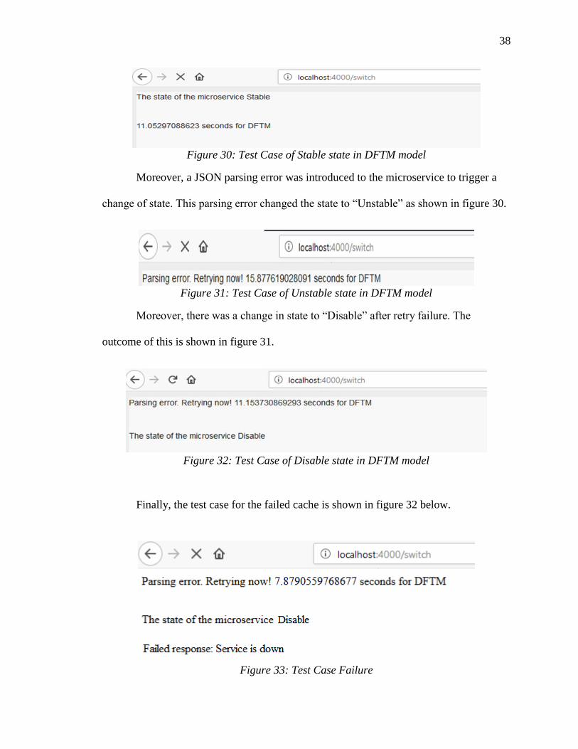
In order to illustrate the results for each test case described in chapter 3, this study
allowed the microservice to run without any form of error, which means the state is
“Stable”. Figure 29 displays the state of the microservices and the running time for
DFTM model while it is on stable state detected by Markov Chain.
38
Figure 30: Test Case of Stable state in DFTM model
Moreover, a JSON parsing error was introduced to the microservice to trigger a
change of state. This parsing error changed the state to “Unstable” as shown in figure 30.
Figure 31: Test Case of Unstable state in DFTM model
Moreover, there was a change in state to “Disable” after retry failure. The
outcome of this is shown in figure 31.
Figure 32: Test Case of Disable state in DFTM model
Finally, the test case for the failed cache is shown in figure 32 below.
Figure 33: Test Case Failure

39
Table 4 below summarizes the test case with the test data and the result for each
of the cases – stable, unstable and disable states.
Table 4: Test Cases Description TEST
CASE ID
TEST CASE
Description
TEST DATA EXPECTED
OUTPUT
ACTUAL
OUTPUT
T_1 Stable when the
microservices
run perfectly
without any
form of error,
which means
the state is
“Stable”.
Response time:
dynamically generated,
URL:
http://localhost:4000/test,
Response time:
dynamically generated
DFTM model
will displayed
the state of the
microservices
and the running
time for DFTM
model while it
is on stable
state as detected
by Markov
Chain.
Figure 29
T_2 Unstable when
a JSON parsing
error was
introduced to
the
microservice to
trigger a change
of state. This
parsing error
changed the
state from
Stable to
“Unstable”
URL:
http://localhost:4000/test,
Response time:
dynamically generated,
Jason response: false
DFTM model
detect fault and
retry
mechanism will
cover the fault.
Figure 30
T_3 Disable when
there was a
change in state
to “Disable”
after retry
failure.
URL:
http://localhost:4000/test,
Response time:
dynamically generated,
Jason response: false,
Number of retries: 3
DFTM will
determine the
state as disable
and retry will
send it to cache
to recover
Figure 31
T_4 Cache has a
failure.
A failed
response will
appear
Figure 32

40
Chapter 5 Evaluation
This chapter evaluates the dynamic fault tolerant model for the microservice. As
stated previously, this research aimed for achieving a stable microservices architecture
using the Stability Patterns with Markov Chain. Also, it intended to increase the
performance and reliability of microservices architecture. For that, the evaluation of the
reliability and performance was performed as follows:
5.1 Reliability
The reliability of DFTM was compared with a Circuit breaker after a failure is
detected. The circuit breaker will open and wait until manually set timeout has elapsed.
However, DFTM Model responded at an almost negligible microsecond after the failure
has been detected and recovered as seen in table 5 below. DFTM eliminates the usage of
timeout by dynamically continuing the execution after detecting a fault. The + in the table
shows the additional time it took the DFTM to run after fault detection while the circuit
breaker did not execute which made the execution time of circuit breaker zero for all the
number of times of trial as shown in the table below.
Table 5: Reliability Execution Time Comparison
N DFTM Model (s) Circuit breaker (s)
1 +0.71924614 0
2 +0.764889917 0
3 +0.705334139 0
4 +0.774148216 0
5 +0.768445978 0

41
The circuit breaker was observed to timeout at the set time while DTFM delivered
the response at negligible additional time ranging from 0.72s to 0.77. The reliability of
DFTM model is better than the circuit breaker.
5.2 Performance
The performance of DFTM was evaluated by generating the execution time of
DFTM model in comparison with the circuit breaker. The evaluation steps are as follows:
• Generation of execution time of circuit breaker.
• Generation of execution time of DFTM Model.
• Repetition of steps 1 and 2 for ten (10) times as shown in table 6 below.
• Calculation of average execution time of DFTM model.
• Calculation of average execution time of Circuit Breaker.
• Calculation and comparison of Percentage Performance of DFTM and Circuit
breaker.
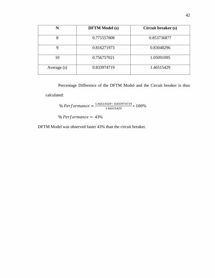
Table 6: Performance Execution Time Comparison
N DFTM Model (s) Circuit breaker (s)
1 0.72924614 2.351104021
2 0.804889917 1.343371868
3 1.005334139 2.295579195
4 0.784148216 2.155514002
5 0.758445978 0.734778166
6 0.876322985 0.817534924
7 0.986773014 2.21852994
42
N DFTM Model (s) Circuit breaker (s)
8 0.771557808 0.853736877
9 0.816271973 0.83048296
10 0.756757021 1.05091095
Average (s) 0.833974719 1.46515429
Percentage Difference of the DFTM Model and the Circuit breaker is thus
calculated:
% 𝑃𝑒𝑟𝑓𝑜𝑟𝑚𝑎𝑛𝑐𝑒 =1.46515429− 0.833974719
1.46515429∗ 100%
% 𝑃𝑒𝑟𝑓𝑜𝑟𝑚𝑎𝑛𝑐𝑒 = 43%
DFTM Model was observed faster 43% than the circuit breaker.

43
Chapter 6 Conclusion
Dynamic Fault Tolerance (DFTM) model is designed to solve the inherent
problem of fault tolerance in the microservices architecture. This chapter is divided into
two sections; conclusion which summarizes the thesis with a general overview of the
presented study and future works which provides the summary of important
considerations that can be taken into to enhance the research.
6.1 Conclusion
Microservices architecture is an autonomy service architecture with the sole aim
of making application development and deployment very easy. Microservices
architecture has several influential advantages, which makes its acceptance level on an
exponential growth across the world.
However, one of the major challenges of this architecture is failures or faults in
one of the microservices leading to the breaking down of the whole system. Therefore,
fault tolerance emerges as a sub-area of microservices, which tends to provide stability,
reliability, robustness, and resiliency to the architecture by using stability patterns.
There are many Stability patterns (Circuit breaker, Timeout, Bulkhead, Fail Fast,
and Retry) to achieve fault tolerance. However, in order to achieve a better performance
and reliability, this study modified circuit breaker, which uses manually set timeout in a
dynamic environment of microservices, which may affect the effectiveness and reliability
of the architecture. This thesis modified the circuit breaker to create DFTM (Dynamic
Fault Tolerance Model) using Switch Circuit Breaker with Markov Chain to dynamically
determine the state of the microservices, retry pattern and cache. DFTM was found to be
44
faster and better than the original Circuit Breaker. DFTM has a better performance and
reliability while achieving the architecture’s stability.
6.2 Future work
This thesis provides stability through Markov chain, thereby eliminating the use
of static timeout in circuit breaker. This thesis can be further improved as future work as
stated in the following sub-sections.
6.2.1 Consider determining types of faults
As a future work, Machine Learning techniques can be used to determine various
types of faults and apply the corresponding recovery stability pattern(s). Each of the
stability patterns has its own inherent strengths, and the use of ML will decide the
appropriate stability pattern for the type of the faults or failure. This will prevent the
usage of multiple hybrid stability patterns. Thereby, developing a data-driven fault
tolerance microservices architecture to ensure the autonomous fault tolerance in the
microservices architecture and a higher reliability and performance.
6.2.2 Consider catching a failed response
The major aim of dynamic fault tolerant DFTM model is to ensure there is high
availability of the microservices, so other forms of stability patterns can be explored.
Failover can be used to protect cache system from returning a failed response. In
addition, Fail-fast pattern can be used with bulkhead pattern to achieve a better fault
isolation.

45
REFERENCES
[1] N. Alshuqayran, N. Ali, and R. Evans, “A systematic mapping study in
microservice architecture,” Proc. - 2016 IEEE 9th Int. Conf. Serv. Comput. Appl.
SOCA 2016, pp. 44–51, 2016.
[2] F. Montesi and J. Weber, “Circuit Breakers, Discovery, and API Gateways in
Microservices,” Sep. 2016.
[3] N. Dragoni et al., “Microservices : Yesterday , Today , and Tomorrow,” Springer
Int. Publ. Cham, pp. 195–216, 2017.
[4] M. Richards, Microservices AntiPatterns and Pitfalls. O’Reilly Media, Inc., 1005
Gravenstein Highway North, Sebastopol, CA 95472, 2016.
[5] M. Garriga, “Towards a taxonomy of microservices architectures,” in Lecture
Notes in Computer Science (including subseries Lecture Notes in Artificial
Intelligence and Lecture Notes in Bioinformatics), 2018, vol. 10729 LNCS, pp.
203–218.
[6] I. Mistrík, R. Soley, N. Ali, J. Grundy, and B. Tekinerdogan, Software quality
assurance: In large scale and complex software-intensive systems, 1st ed. {San
Francisco, CA, USA: Morgan Kaufmann Publishers Inc., 2015.
[7] N. Wu, D. Zuo, and Z. Zhang, “An extensible fault tolerance testing framework for
microservice-based cloud applications,” 2019, pp. 38–42.
[8] M. Kalske, N. Mäkitalo, and T. Mikkonen, “Challenges When Moving from
Monolith to Microservice Architecture,” in Lecture Notes in Computer Science
(including subseries Lecture Notes in Artificial Intelligence and Lecture Notes in
Bioinformatics), 2018, vol. 10544 LNCS, pp. 32–47.
46
[9] K. Indrasiri and P. Siriwardena, Microservices for the Enterprise. 2018.
[10] P. Jamshidi, C. Pahl, N. C. Mendonça, J. Lewis, and S. Tilkov, “Microservices The
Journey So Far and Challenges Ahead,” 2018.
[11] S. Haselb, R. Weinreich, and G. Buchgeher, “An Expert Interview Study on Areas
of Microservice Design,” 2018.
[12] T. Hunter II, Advanced Microservices. 2017.
[13] M. Ima, “Microservices vs. SOA.” [Online]. Available:
https://dzone.com/articles/microservices-vs-soa-2. [Accessed: 18-March-2019].
[14] J. Fowler, M. and Lewis, “Microservices,” Microservices, 2014. [Online].
Available: https://martinfowler.com/articles/microservices.html. [Accessed: 20-
May-2019].
[15] L. Florio, E. Di Nitto, D. Elettronica, I. Bioingegneria, P. Milano, and A.
Microservices, “Gru : an Approach to Introduce Decentralized Autonomic
Behavior in Microservices Architectures,” 2016.
[16] Y. Sun, S. Nanda, and T. Jaeger, “Security-as-a-Service for Microservices-Based
Cloud Applications,” in Proceedings of the 2015 IEEE 7th International
Conference on Cloud Computing Technology and Science (CloudCom), 2015, pp.
50–57.
[17] C. E. de Oliveira, Spring 5.0 By Example. Packt Publishing, 2018.
[18] M. T. Nygard, Release It!, vol. 5, no. 9. 2014.
[19] N. Mashashi, B. Alex, W. Mike, W. Mar, and F. Sam, “Retry pattern.” [Online].
Available: https://docs.microsoft.com/en-us/azure/architecture/patterns/retry.
[Accessed: 15-March-2019].

47
[20] N. Mashashi, B. Alex, W. Mike, W. Mar, and F. Sam, “Cache-Aside Pattern,”
2018. [Online]. Available: https://docs.microsoft.com/en-
us/azure/architecture/patterns/cache-aside. [Accessed: 12-Jan-2019].
[21] P. Victor and L. Lewis, “Markov Chains,” 2014. [Online]. Available:
http://setosa.io/ev/markov-chains/. [Accessed: 12-May-2019].
[22] J. Sejal, “Markov Chains in Python: Beginner Tutorial,” 2018. [Online]. Available:
https://www.datacamp.com/community/tutorials/markov-chains-python-tutorial.
[Accessed: 29-April-2019].
[23] S. Devin, “Introduction to Markov Chains,” 2018. [Online]. Available:
https://towardsdatascience.com/introduction-to-markov-chains-50da3645a50d.
[Accessed: 2-May-2019].
[24] S. Haselbock, R. Weinreich, and G. Buchgeher, “Decision guidance models for
microservice monitoring,” in Proceedings - 2017 IEEE International Conference
on Software Architecture Workshops, ICSAW 2017: Side Track Proceedings, 2017,
pp. 54–61.
[25] G. Toffetti, S. Brunner, M. Blöchlinger, F. Dudouet, and A. Edmonds, “An
architecture for self-managing microservices,” 2015, pp. 19–24.
[26] I. Cassar, A. Francalanza, C. A. Mezzina, and E. Tuosto, “Reliability and Fault-
Tolerance by Choreographic Design,” Electron. Proc. Theor. Comput. Sci., vol.
254, pp. 69–80, Aug. 2017.
[27] W. Tang, L. Wang, and G. Xue, “Design of High Availability Service Discovery
for Microservices Architecture,” pp. 253–257.
[28] D. Mingxiao, M. Xiaofeng, Z. Zhe, W. Xiangwei, and C. Qijun, “A Review on
48
Consensus Algorithm of Blockchain,” pp. 2567–2572, 2017.
[29] B. M. B and M. Almiani, Advanced Information Networking and Applications, vol.
926, no. i. Springer International Publishing, 2020.
[30] D. Preuveneers and W. Joosen, “QoC Breaker: intelligent software circuit breakers
for fault-tolerant distributed context-aware applications,” J. Reliab. Intell.
Environ., vol. 3, no. 1, pp. 5–20, Apr. 2017.
[31] Matt Jacobs, “Hystrix Defend Your app,” 2017. [Online]. Available:
https://github.com/Netflix/Hystrix/wiki. [Accessed: 26-Apr-2019].
[32] A. Rotem-Gal-Oz, “Fallacies of Distributed Computing Explained (The more
things change the more they stay the same),” p. 20, 2016.
[33] N. Sam, Building Microservices. O’Reilly Media, 2015.
[34] L. Lamport, “Using Time Instead of Timeout for Fault-Tolerant Distributed
Systems.,” ACM Trans. Program. Lang. Syst., vol. 6, no. 2, pp. 254–280, Oct.
2014.
[35] Pivotal, “Spring Boot,” 2015. [Online]. Available: https://spring.io/projects/spring-
boot. [Accessed: 10-Jun-2019].
[36] Pivotal, “PetClinic,” 2016. [Online]. Available: https://github.com/spring-
petclinic/spring-petclinic-microservices. [Accessed: 20-May-2019].