a diagnostic study in a husk fired boiler for a power plant
DESCRIPTION
This is a diagnostic report on a rice husk fired AFBC boiler which experienced combustion issues.TRANSCRIPT

5 January, 2013
REPORT ON BOILER OPERATION ON RICE HUSK
By K.K.Parthiban, Boiler consultant
The visit was made to resolve the combustion problem with rice husk. As per request the boiler was shut & offered for internal inspection. The boiler was internally inspected and many modifications were suggested and the same were immediately implemented. The boiler was running properly with rice husk after the modifications and after some changes were made in operational parameters from the past practice. The detailed report is as below.
ABOUT THE BOILER
The FBC boiler is a top supported over fed FBC boiler, supplied by Thermax, Pune. The boiler parameters are 70 TPH, 66 kg/cm2g and 490 deg C with feed water temperature of 180 deg C. The design fuels are 100% coal and 100% rice husk. The combustor is with open hopper system. The boiler was commissioned on coal quite long back. Recently the rice husk was fed. There were problems of ash settling inside the furnace within a week of boiler operation on rice husk. The boiler is with ESP. The ESP first field is burnt heavily due to combustion of rice husk inside. The boiler has four coal feeders for the four compartments. The boiler has three rotary feeders through which the husk is fed. Unfortunately the husk feeders are placed in between the compartments and hence boiler light up by rice husk is not possible in the present design.
DESIGN REVIEW OF THE BOILER
By comparing the boiler with few open hopper boilers, it is seen that the boiler is basically a coal fired boiler with overbed firing. Due to husk option, the coal feeders were kept at a higher level without increasing the furnace volume. The boiler is not designed to start on rice husk as the husk feed port is in between the compartments.
The furnace volume available for rice husk is 2.7 sec. This is OK for dry husk. However the husk feeding should be proper with adequate secondary air. The second level SA is not to be used for rice husk. The DP nozzle drop is calculated to be 276 mmWC. In order to have proper combustion at least 580 mmWC air box pressure is required to be maintained. The bed coils are found to be adequate for sustaining a reasonable bed temperature. Usually it is around 650 -700 deg C in overbed.
OBSERVATIONS AND MODIFICATIONS IN SHUT BOILER
The following were the modifications carried out as per suggestions given by undersigned.
1. The rotary damper in husk spreader was put back in operation. The rpm was reduced to 1 rpm by changing the sprocket at the driven end.
2. All husk feed chutes were provided with a top curtain air by taking a tapping from the bottom level SA header.
3. The thermocouples were placed at 50 mm above top of air nozzles.
4. The bed height manometer was put in place. Compressed air purging provision was given.

5. The boiler was inspected at economiser inlet, economiser middle, economiser bottom, APH bottom, APH middle and APH top. The ESP fields & penthouse were inspected. The observations are listed below.
a. All inspection doors in flue path have to be with an insulation box inside the door so that the flue gas condensation can be prevented.
b. In ESP doors, the sealing ropes become harder in service. The ropes are to be replaced whenever the doors are opened. Otherwise it leads to casing corrosion. This was shown to electrical engineer.
c. In between the two doors of ESP inspection doors, 100 mm thick mineral wool mattress shall be packed.
d. The ESP penthouse insulation shall be rectified. Otherwise the corrosion of roof casing will be experienced.
e. The ESP penthouse pressurising blower should never be tripped.
f. The ESP penthouse pressurising blower duct inside ESP shall be extended by 250 mm. This will avoid the insulation getting disturbed.
g. The economiser banks would need perforated plate baffles on the bend side above and below each bank. There are three banks. The cable tray of 100 / 150 mm width can be used as perforated baffles. These are to be welded with the casing at 50 mm above and below each bank.
6. APH leak test was conducted. Nearly 25 tubes are found to be leaking. These tubes have to be replaced. In fact, once some tubes fail, it implies that the tubes of the entire block have served their life. Continuing with some old tubes, will be a nuisance.
7. The ACC tube inside was seen. It is advised to raise the condensate pH to 9 so that the white metal seen at inlet of the tubes can be avoided.
8. The ACC side cladding to floor sealing was not done. Light could be seen from the clearances. These shall be closed by a layer of concrete.
9. The husk spreader trial was conducted in feeder no 3. The spreader pressure of 300 mmWC was found to be required to spread the husk (MCR husk feed rate) in to the furnace.
10. The air cooled condenser side sheeting shall be sealed with the floor, so that air flow is effectively used in condensate formation in ACC. Normally it is done by cement and mixture plastering. See a typical photo attached in annexure.
11. The sub cooling of condensate must be reduced to save fuel. The heat loss in the piping from ACC bottom header to the deaerator can be reduced by insulation.
12. The FD fan isolation gate needs roller support both outside and inside. The threaded worm screw part must be provided with a dust cover. The frame shall be closed at top & bottom to prevent the dust deposition on the worm screw.

13. The bed material that was inside bed did not fluidise even at 900 mmWC air box pressure. Two compartments were taken for fluidisation. Even two FD fans could not lift the material. The 100 nb drain pipes provided for FD air headers were flushed out. Higher size bed material was found inside the FD air headers. It meant there had been regular seepage of bed material in to the header. 50 nb drain valves were advised for each drain header. These were provided immediately.
14. The bulk density of fresh sieved material was checked to be 860 kg/m3. Fresh sieved material was filled up to 250 mmWC above air nozzle. This material was found to fluidise at 660 mmWC air pressure and at a flow of 75 TPH. This time one FD fan was used to fluidise the bed.
15. Then the rotary screen used for sieving of bed ash was inspected. The screen was found to have 4 mm square aperture. This screen cloth was changed with a 3 mm square aperture. This would reduce the air flow requirement for cold fluidisation.
16. The boiler roof was found to be with ash spillage. The nearby insulation cladding sheets were seen corroded. The roof needs to be plastered with POP as per suggestion given in annexure. The oxygen sensed by the Oxygen analyser would include the air ingress.
17. The expansion bellows at ID fan suction and discharge are interfering with the ID fan casing itself. The expansion bellows and damper can be moved away from the spiral casing of the ID fan. At present there is no access to tighten the flange. The flue gas is found to leak and the cladding sheet has corroded already.
18. The expansion bellow at ID fan is seen corroded already.
OBSERVATIONS DURING BOILER OPERATION
The boiler was lighted up in my presence on 4th Jan evening. Charcoal was spread leaving a gap of 300 mm from all edges of the first compartment. The bed temperature could be raised up to 650 deg C. As the air flow was more for fluidising purpose (30 TPH), additional 10 bags of charcoal was used before coal feeding. The coal took a long time to catch fire since the fines were high. The coal also contained dolochar which is a tough fuel for start up. There was tripping of coal feeders and the start up was disturbed. Somehow things were rectified, and boiler was running on coal by 5th Jan morning. The parameters were as below with 13 MW generation. Air box pressure 650 mmWC SA pressure at first level was at 100 mmWC SA pressure at second level was at 400 mmWC Air flow was at 100 TPH. Oxygen was at 5.5 to 6 %. Only one FD was used at 95% opening. The LOI of ash was found to be 5.5 to 7 at various ash collection points.
The rice husk changeover was done at around 1 PM. The coal feeder rpms were brought down and husk feeders rpm were raised. The upper SA header was closed fully. The lower SA header pressure was kept at 500 mmWC. The air flow was brought down to 86 TPH to keep oxygen at 6 to 7%. The air box pressure must be maintained at 580 mmWC to keep the bed temperature at 625 to 650 deg C.

This was the highest bed temperature that could be achieved. The furnace pressure was just at 0.35 mmWC. The DESH spray was found to be at 65 to 70%. The free board temperature was ranging from 730 to 770 deg C. The APH outlet gas temperature was at 142 deg C. The following are the recommendation after seeing the operation. The LOI of ash was found to be 5 to 7%. The bed material inside the furnace was still having 38% above 3 mm. For pure husk firing this is not OK. River sand of 2 mm and below and bed ash of 3 mm and below only can be used as the bed material. This will ensure the bed expands well and burns the rice husk better. a. The ash hopper central plate shall be installed back. See annexure for clarity. This will ensure ash
is drained from all locations. b. It is advised to have additional drains (100 nb pipes) with gates, extended right up to air nozzle
pipes. There can be at least two drains per hopper. This will ensure better size control. This will ensure all thermocouples are active. See sketch in annexure.
c. It is advised to keep the thermocouple at 75 mm above air nozzles so that the temperature read little higher than what is at present.
d. Dense phase system would not be able to handle the voluminous ash from the ESP hopper. Belt conveyor system only may work. At present the ash is being discharged through the rotary feeder from ESP hoppers.
e. The ash is found to flow freely from ESP hoppers. No long unburnt husk is seen in ESP first field hoppers. The Ash LOI is at 5-6.5%. This is OK. Heat loss is less than 3%.
f. The furnace pressure hunting and puffing is not seen. g. The APH and ECO hoppers would not collect much ash in rice husk. This is because the
interconnection duct is within the ash hopper itself. OTHER PROBLEMS Drag chain feeder tripping The drag chain feeder chain length was found to be more and there was considerable slack. There is no sufficient adjustment length available to remove two links in the drag chain. This needs to be modified with a minimum of 300 mm adjustment. Use of EN link plates is advised. Coal feed hopper jamming The Coal feed hopper gates should always be kept open. The hopper can be provided with SS liner plates for free flow of coal. The gate used for level control can be curved as explained in person. Bed ash from the present coal The coal used at present contains calcium carbonate. The ash is white in color. There are ash mounts seen over the APH tube sheet. It was reported that there had been ash agglomerations inside the ash hoppers. The presence of CaCO3 leads to ash agglomeration and not fused clinker. Bed particle size for rice husk The size of the bed material is should be less than 3 mm for the bed material generated from the

present coal ash. We can use river sand as the bed material. The size has to be < 2 mm. With river sand the consumption of bed material would come down. The abrasion goes up little bit. The bed coil polishing should be observed. As the bed coil is away from the nozzle by 350 mm, this phenomenon will be lesser. Wet husk / decayed husk The rpm of fuel feeder would be dependent on GCV of the decayed husk. Also wet husk would needs additional fuel to evaporate the fuel moisture. The wet husk would not burn fully in the furnace. It would rise the boiler bank outlet gas temperature. Boiler thermal expansion and the seal around the furnace The sealing arrangement provided by Thermax is OK. One can add a fabric joint if complete seal is required. But fabric seal also burns off. It gets packed with bed material after few cycles of boiler operation. The warping of the seal plate cannot be avoided as it comes under cycling heating and it expands differentially as compared to bottom header. Pouring cold bed material at leaky point is the trick adopted by some boiler operators. FURTHER RECOMMENDATIONS ON START UP 1. The bed material height shall be 250 mm above the nozzle for start up. 2. A border of 300 mm shall be made between the first & second compartment by fine bed material.
This is to prevent the spillage of the charcoal to adjacent bed. 3. The FD duct drains shall be operated after the light up is completed and all compartments are
brought in. the ball valve shall be opened for two or three seconds only to remove the seeped material. Since the hole size in the air nozzle is 4.7 mm, the seepage will be more during start up and during hot slumping and restarting.
4. The bed material size shall be less than 3 mm if it is from the present coal and if it is less than 1100 kg/m3 bulk density. In case the coal ash is having a bulk density of 1200 and above, the bed material has to be between 2.35 (8 no sieve) mm and (20 no sieve) 0.85 mm. If sand is used, the bed material size should be less than 2 mm and over 0.5 mm.
5. The charcoal quantity for start up should be optimised for a bed temperature rise up to 850 deg C. 6. During start up, once the top layer charcoal reaches red hot, mixing should be done at minimum
fluidising air flow for 30 seconds. This will ensure the charcoal is thoroughly mixed. After the mixing the air flow should be raised in steps until the air box pressure reaches 450 mmWC. As the bed is well fluidised and coal fire is established, the air box pressure can be further increased by adding more bed material. The air flow shall be between 25- 30 TPH for first compartment.
FURTHER RECOMMENDATIONS FOR HUSK FIRING 1. The air box pressure shall be minimum 580 mmWC and maximum 620 mmWC. 2. The airflow shall be between 85 to 90 TPH. 3. The secondary air pressure shall be tuned between 400 mmWC to 500 mmWC until the best fly
ash is achieved. 4. The upper level SA shall not be used.

5. The oxygen shall be between 5.5 and 6.5. Once the roof is sealed well, the oxygen in flue gas shall be between 4.5 & 5.5.
6. The ash hopper needs to be drained based on the particle size and bulk density increase in the bed. Conditionally some ash had to be drained and replenished to ensure the over size and stone particles get out of the furnace.
7. All fuel feeders’ speed should be raised or lowered in unison. Increasing the fuel feed rate of one feeder is not correct.
8. The ESP ash color should be checked by DCS personnel to understand the husk quality variance and the bed material quality variance.
9. It may be possible to manage with one ID fan. This is to be checked after the isolation gate is installed.
FURTHER RECOMMENDATIONS FOR COAL FIRING 1. The air box pressure shall be minimum 650 mmWC and maximum 750 mmWC. 2. The airflow shall be between 90 to 100 TPH. 3. The secondary air pressure shall be tuned between 300 mmWC to 400 mmWC until the best fly
ash is achieved. 4. The upper level SA shall not be used. 5. The oxygen shall be between 5.5 and 6.5. Once the roof is sealed well, the oxygen in flue gas
shall be between 4.5 & 5.5. 6. The ESP ash color should be checked by DCS personnel to understand the air flow split between
SA & bottom air and the bed ash settling. 7. The iron containing particles in ash should be restricted to < 15%.
FURTHER RECOMMENDATIONS IN COMBUSTION SYSTEM It is not required to modify to underbed system as the LOI is within control. Under bed feeding
may improve the LOI by 1%. But the gain efficiency may be 0.7% only. Since the superheater temperature and boiler outlet gas temperature is under control, modification is not necessary.
Husk feeders have to be each one for each compartment, if we desire to start the boiler on rice husk. Otherwise no modification is required.
If efficiency is to be improved in coal firing combined spreader is required for coal & husk. This concept is new. The layout is suggested in annexure.
K.K.Parthiban.


ANNEXURE 1 – OBSERVATIONS & RECOMMENDATIONS

Photo 1 & 2: The seepage of bed material / bed ash in to the FD ducts.

Photo 3 & 4: The air nozzle hole size is 4.7 mm. During slumping and start up there can be seepage of bed ash.

Photo 5: The air nozzles levels were found to be non uniform by RRPL engineer during a shutdown of the boiler. In the presence of OEM, the air nozzle levels were corrected by adjusting the FD air headers.
Photo 6: The hopper had got warped due to excess heat. In addition the load transfer to supporting system was not good. There is no refractory lining seen. It must have got deteriorated over a period. The FD duct bottom had got flattened. The bottom must have got overheated due to bed material seepage inside.
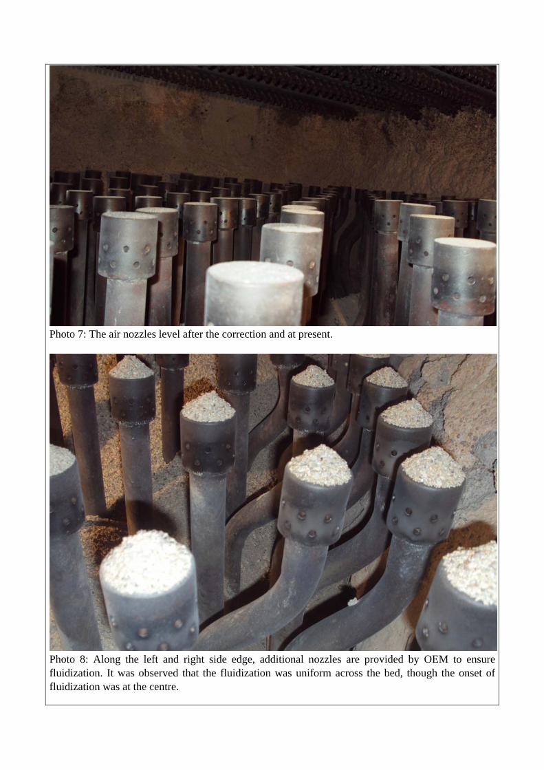
Photo 7: The air nozzles level after the correction and at present.
Photo 8: Along the left and right side edge, additional nozzles are provided by OEM to ensure fluidization. It was observed that the fluidization was uniform across the bed, though the onset of fluidization was at the centre.

Photo 9: Many thermocouples were found to be projecting above the air nozzles by 150 – 250 mm above air nozzles. The operators may allow the stones to settle up to the thermocouple level. This may reduce the actual operating bed height.
Photo 10: During the visit, it was recommended to place thermocouple tip at 50 mm above air nozzle top. Operators would now drain the coarse particles once they settle up to thermocouple tip.

Photo 11: The size of the seepage bed material seen from the FD header drain flange.
Photo 12: This shows the oversize particles present in the bed material being used. Seeing this it was advised to change the screen and the same was already done.

Photo 13: The Size of the screen in the rotary screen used at the plant is seen here. The aperture size was 4 mm. Now it is changed to 3 mm.
Photo 14: The vibrating screen originally used before June 2012 was OK.

Photo 15: When the bed material was filled up to 250 mm above the air nozzle, the top of the bed is seen to be just below the bed coil. The bed coils are well placed for over bed feeding system.
Photo 16: The bed material bulk density had been maintaining at 970 kg/m3 unlike other coal fired boilers. It is generally around 1250 kg/m3.

Photo 17: The old bed material was found to fluidize at 660 mm with an air flow of 75 TPH for two compartments. This was noted for startup purpose. If we subtract the bed height of 250 mm, the DP drop corresponding to fluidization was 410 mmWC. This is quite a high DP drop for minimum fluidization. This was due to oversize particles.
Photo 18: When the bed material is between 2.35 mm and 0.85 mm, the bed material fluidizes at a fluidization velocity of 0.7 m/s. When the particle size is on the higher side, the DP drop would increase. At 270 + 250 = 520 mmWC air box pressure, the bed fluidizes.

Photo 19: When the particle size is higher, the fluidization velocity goes high. The pressure drop across air nozzle can go up to 250 + 350 = 600 mmWC due to this.
Photo 20: MCR DP for coal with 85% air from bottom is around 320 mmWC. With an operating bed height of 400 mmWC, the air box pressure can be around 720 mmWC on coal. 15% of the total combustion air goes for secondary air.

Photo 21: MCR drop across DP with 20% SA for rice husk case. This is due to the fact that the rice husk has fuel oxygen in it. With a bed height of 300 mmWC, the air box pressure has to be = (284 +300) = 584 mmWC for the case of rice husk.

Photo 22: Air required for coal at 35% EA is 102 TPH. Gas produced is 110 TPH.

Photo 23: Air required for Rice husk at 35% EA is 104 TPH. Gas produced is 110 TPH. With increase in fuel oxygen, the air requirement would come down.

Photo 24: The second level SA ports provided for coal are almost very close to the superheater. When the coal contains fines, the DESH spray requirement will be more.

Photo 25: The coal feed openings are placed above the husk feed openings. Ideally all should have been close to the fluidized bed to make use of the combustor volume.

Photo 26: The husk spreader trial was checked with MCR husk feed rate. At 300 mmWC, the husk was seen to spread to centre. The heap at left was when the air pressure was at 100 mmWC & 200 mmWC. Earlier so far only 75 mmWC was used to spread the husk.
Photo 27: The husk was found have charred on the bed tube. During the previous 4 hours of husk firing, soft husk ash agglomerations were seen.
char
Mount with 75 ‐200 mmWC
spreader pressure Mount with 300 mmWC
spreader pressure

Photo 28: An air curtain was added in the fuel chute to prevent back fire from the furnace and to make the husk flow downwards. 5 x 20 dia holes were provided in the 80 nb pipes.

Photo 29: The rotary damper system was reinstalled in the pneumatic husk spreader. The sprocket size was changed to reduce the speed from 3 rpm to 1 rpm.
Photo 30: 80 nb ball valves were added at all FD air headers to remove the bed material seepage on line. This should be operated once in a shift / day depending on the experience from now on.

Photo 32: Soft agglomerations are formed in the ash hopper. This can be due to lime shales present in the fuel ash. The ash can be chemically analyzed at an outside laboratory to understand the ash chemistry.
Photo 33: The expansion joint is corroded at ID fan discharge. This calls for replacement.

Photo 34: The expansion bellow at ID fan suction and at discharge must be leaky. The claddings sheets are seen to have corroded due to flue gas leakage. The damper and expansion bellow should have been placed away from the casing volute so that accessibility is available.

Photo 35: The view of the economiser from bottom. The gap between the casing and the tubes is varying. This can cause erosion. Perforated cable tray can be used as baffles to slow down the ash velocity and to limit the gas flow in between the tube and the casing.
Photo 36: Many APH tubes are seen to have been plugged. When the tubes begin to fail, it implies they have served their life. With husk, the tubes last for 2 years. With coal they last for 4-5 years.

Photo 37: ESP penthouse insulation is very poor. This shall be rectified as the casing corrodes at faster rate with rice husk.
Photo 38 & 39: The emitting electrode rapping system is seen open to atmosphere. This can lead to water seepage in to non conductor between the field and the hammer. On the right the hood arrangement followed at another plant is shown.

Photo 40: The ESP inspection door is seen to corrode. These corroded flakes fall in to the dense phase system causing choking. It is advised to replace the sealing rope whenever the door is opened. Insulation mattress of 100 mm thickness shall be provided in between the outer & inner doors.

Photo 41: The ash leakage above the nose is due to left out welding between the nose panel and the side panel. This may be attended.
Photo 42: The clamps in PSH are seen to have failed due to combustion in SH area.

Photo 43 & 44: There is enough leakage of flue gas to corrode the cladding sheet of the insulation at roof. Ash is seen over the SH headers.

Photo 45: General drawing of plaster of paris / Cement + Mineral wool + Sand mastic finish on insulation which helps on sealing. This shall be done at roof tube area.
Photo 46: The simple method of going for plaster of paris gives the result. This shall be followed for arresting the leakages. This process involves sealing as per OEM drawing, followed by roof insulation mattress + POP + hessian cloth + Black bitumen paint.

Photo 47 & 48: Top photo shows the doors are not provided with proper sealing rope and insulation box to prevent condensation of flue gas inside the manholes doors in the flue path. Bottom photo shows the insulation box and flat sealing rope at the door. All the inspection doors shall be corrected.

Photo 49: The light is seen between the ACC side sheet and the floor. This leads to loss of air flow from the fan. This shall be sealed by concrete.
Photo 50: The photo shows the burnt collecting electrodes in first field of ESP. This can happen due to accumulation of burning husk / unburnt husk & ash right in to the field. The dense phase system provided here is not suitable for rice husk. Alternate conveying arrangement is required. During the visit it was seen that the loader was required here continually.

Photo 51: There is white metal seen inside the ACC tubes. The pH has to be slightly improved from 8.5 to 9 in the condensate return.
Photo 52: This is an extract from an article. The corrosion rate is less when the pH is higher. This is particularly true for systems with ammonia. The breakdown of morpholine / hydrazine is less at boiler pressure of 66 kg/cm2 and hence there is no report on iron increase in condensate. However the corrosion can be minimized using pure chemicals from Ranbaxy / Merck.

Photo 53: The boiler rearwall is fixed in this boiler. The front of the boiler moves by 33 mm. The boiler comes down by 54 mm as per this drawing., The left side and right side expansion is 8 mm. This almost matched the expansion once the boiler reached rated pressure.
Photo 54: The 700 mm sq plate shall be fitted back in all furnace hoppers. This enables the discharge of ash across the entire bed. The plate thickness shall be increased to 12 mm.

Photo 55: It may be possible to location ash drain pipes at furnace hopper, which would enable to drain the bed ash locally near the nozzle level. This would prevent overheating of the hopper. These pipes have to be of SS. Depending on the way of coarse particle accumulations, these drain pipes can be placed. The pipes have to be extended up to the air nozzle pipes.
Photo 56: It would be necessary to arrange four husk feed ports, that is one feed port per compartment. It is possible to combine the coal feeding in to a single spreader with pneumatic cum rotary spreader. This will enable use of complete combustor volume.

Photo 57, 58 & 59: The LOI report of ESP I, II, III and APH ash on rice husk firing is seen here. As per the worst LOI, the percentage heat loss is 2.73%. This is a small amount.

Photo 60: The continuous ash removal is a must at ESP. If not removed, the ash will accumulate within the ash hopper and create problem. The ash volume is more in rice husk ash and hence dense phase system may not take it. It may be possible to redesign the transmitter vessel and pipe line size. Ash handling system supplier has to be consulted.
Photo 60: The boiler log with rice husk firing is seen here. The O2 and furnace temperatures, spray valve opening, steam pressure were steady during the operation. Only hitch was that the bed height could not be built up as the bed material consumption was very high. The particles seemed to break down very fast. Hence sand was recommended as the bed material. The best bed temperature is 644 deg C. Other thermocouples have to be revived by draining and charging bed material.

Photo 60: The isolation gate shall be provided with top and bottom cover plate to avoid dust settling at worm shaft. Also a pipe with end cover shall be added for the extended worm screw. The rollers are to be provided at outside the air path also to minimize the friction. Liner electric actuators can be used for open / close action. 4 inch power cylinder can also be used. Higher torque is possible only with electrical actuator.
Photo 61: The husk hopper can be made in to four by cutting the present hoppers and replacing with new hoppers below the tie beam. Such a modification is required for feeding the husk in all compartments.

Photo 62 & 63: The drag chain feeder tensioning ( take up) adjustment is locked. The tensioning length available should be at least 300 mm. The spring base itself should be movable to achieve this. By modifying this, the chain climbing over wet coal (Top photo) can be avoided.

Photo 64: The Fuel feeding system to the boiler may be modified as shown for starting the boiler on rice husk and to have flexibility in operation such mixing of fuels and using the entire furnace volume.