a detailed look at some valve train · pdf filea detailed look at some valve train issues: ......
TRANSCRIPT

From Philip Dingle, Michigan USA
A Detailed Look at Some Valve Train Issues:
Recently, while rebuilding a Jupiter engine I took the opportunity to look at the valve train in some detail and made a number of observations. I will use the term valve train here to cover everything from the camshaft chain sprocket through the camshaft, the tappets, pushrods, rockers and the valve and springs sub-assembly. I could have used the term valve gear instead, but that sounds a trifle outdated nowadays, although it would have been the current terminology in 1950.
There is a huge amount of technology in valve trains and I would have liked to have had the time to go into it in greater depth, but at least this is a start. We should begin by recalling that in a 4-stroke engine, the camshaft runs at half the crankshaft speed and is responsible for controlling the timing, duration and lift of the gas exchange [inlet and exhaust] valves. This is relatively easy to do at low engine speeds, but due to component inertias it becomes much more challenging as the engine speed increases. In the case of the Jowett engine, we are encumbered with a quite long and heavy pushrod and a rather flexible rocker shaft that imposes a significant handicap on engine tuning potential. Nevertheless, we should look at what we have to work with and consider our options for improvement.
My first step was to measure as many features as possible. The two critical aspects of a valve train are mass (weight) and stiffness (resistance to deflection), so I recorded what I could in this respect using a sensitive scale for both the early "zero-lash" and later solid tappet [lifter] valve train components:
COMPONENT PART NO. MASS [grams] HYDRAULIC SOLIDTappet [Hydraulic] 107.76 107.76Pushrod [Hydraulic] 99.6 99.6Tappet [Solid] 54161 75.39 75.39Pushrod [Solid] 54162 104.05 104.05Spring Retaining Collar 53307 26.49 26.49 26.49Cotters [2] 50705 4.33 4.33 4.33Inlet Valve 50515 64.39 64.39 63.39Exhaust Valve 50516 58.05 58.05 58.05Inner Valve Spring [Eff.] 50709 11 11 11Outer Valve Spring [Eff.] 52964 21.23 21.23 21.23Rocker [Eff.] - - - -TOTALS 392.85 364.93 From this table, it is immediately apparent that the later solid tappet valve train has a lower mass by almost 28 grams. However, note that this weight reduction is all on the camshaft side of the rocker where in fact the most important criteria is stiffness. Due to the effect of the rocker ratio, which in our case is nominally 1.5:1, low mass is more important on the valve side of the rocker but in our case that remains unchanged between the early hydraulic tappet and later solid tappet engines. A further caveat relates to the indicated weights for the valve springs. These are given as "effective"
1
mass which is in fact one third of the actual mass, because in a dynamic situation only about 33% of a normal helical spring contributes to the system inertia. Also, I was not able to calculate the effective rotational inertia for the rocker, but it will be essentially the same between early and late engines.
Since valve train stiffness is important on the camshaft side of the rocker, I tried to look at this. Using a laboratory grade spring tester, I was able to get values for a typical pushrod for both the hydraulic and solid type as shown in this table (N.B. 4.448 N = 1 lb):
PUSHROD TYPE DEFLECTION [mm] LOAD [Newtons] STIFFNESS [N/mm]Hydraulic 0.05 500 10,000
Solid 0.03 500 16,667
This data suggests that the solid tappet pushrod is about 40% stiffer than the earlier version for the hydraulic tappet engines. For our purposes, the solid tappet can be taken as being infinitely stiff, but it would not be easy to measure the hydraulic tappet since the stiffness value will be very dependent on the dynamic conditions and the amount of air entrained in the oil. Suffice to say that it will be much less stiff than the solid tappet. Camshaft stiffness in the form of shaft bending between the journals can also be a real problem for pushrod engines, but in our compact engine it can probably be ignored.
Essentially then, the observations so far provide no surprise; relative to the "later" solid tappet mechanism, with the hydraulic tappets you trade top end performance for quiet operation and low maintenance due to the wear-compensating capability. While this statement is probably true for all hydraulic tappet engines of any make, it is particularly true for the Jowett engine because of the differential expansion issues (discussed later) and the relatively high valve train wear rates.
Next I took the opportunity to measure some valve springs. I had two sets of new old stock (NOS) springs available to me. Both sets were Terry's "Aero" Valve Springs in their original box; one set was part number VS365 and the other VS462, labeled for the 1952 Jowett Javelin or Jupiter. The VS462 springs appeared to be stronger and, being plated for corrosion protection, more high class than the VS365 springs which were simply greased. The metrics for the two springs are given in the table below:
SPRING WIRE DIAMETER
COILS FREE LENGTH
OUTSIDE DIAMETER
SPRING RATE
Inch / (mm) Inch / (mm) Inch / (mm) Lb/in / (N/mm)365 Outer .143" (3.63) 5 2.06" (52.45) 1.35" (34.29) 83.73 (14.66)365 Inner .119" (3.04) 7.5 1.96" (49.8) 1.00" (25.4) 72.28 (12.66)365 Combined 156 (27.3)462 Outer .160" (4.06) 6 2.10" (53.4) 1.41" (35.81) 106.14 (18.6)462 Inner .122" (3.1) 7.5 2.02" (51.2) 1.01" (25.65) 73.97 (12.95)462 Combined 180.1 (31.55)
Comparing these values to those specified by Jowett Cars Ltd. (JCL), it is apparent that the VS365 spring set meets the original equipment specification, which rather suggests that the 15% stronger VS 462 spring set is a competition specification.
2

In broad terms, higher force springs should allow the engine to run up to a higher speed before valve float intervenes. However, the response is not linear due to compliance in other parts of the valve train. Then there is the issue of contact loading or Hertzian stress between cam and tappet. For the materials that our cam and tappet are made from, the contact loading should not exceed about 130,000 lb/in2. Higher spring loading is much more likely to wipe out the cam nose radius unless the mating parts are in very good condition.
My next move was to measure and record the cam profile. Now there are specialized but fairly simple machines available for accurate cam profile measurement, but I did not have access to one. These machines place the camshaft between centers and use a stylus to trace the true profile as a function of cam rotational angle. However, at this point, the engine under rebuild was partially assembled and ready to receive the camshaft and so I elected to measure the tappet lift as a surrogate which was easy to do. The point here being that a flat-bottom tappet will not record the same profile as a single point stylus. To accomplish this, I rotated the engine so that the tappet bore was vertical and then set up a dial indicator on the top end of the pushrod with the scale zeroed on the cam base circle. I then mounted a degree wheel on the nose of the camshaft as shown in the photo. Thus there were no loads on the camshaft other than the weight of the tappet and pushrod, and it was easy to rotate it by one-degree increments without the influence of spring forces.
Recording Tappet Lift in the Partially Assembled Engine
By this tedious method, I was able to record the tappet lift as a function of camshaft angle for both an inlet and an exhaust lobe and this yielded the results plotted below.
3
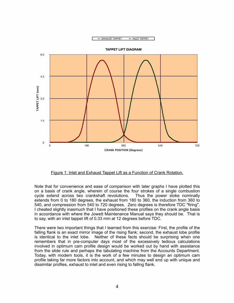
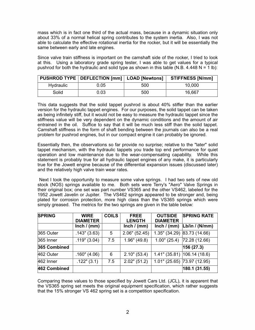
Figure 1: Inlet and Exhaust Tappet Lift as a Function of Crank Rotation.
Note that for convenience and ease of comparison with later graphs I have plotted this on a basis of crank angle, wherein of course the four strokes of a single combustion cycle extend across two crankshaft revolutions. Thus the power stoke nominally extends from 0 to 180 degrees, the exhaust from 180 to 360, the induction from 360 to 540, and compression from 540 to 720 degrees. Zero degrees is therefore TDC "firing". I cheated slightly inasmuch that I have positioned these profiles on the crank angle basis in accordance with where the Jowett Maintenance Manual says they should be. That is to say, with an inlet tappet lift of 0.33 mm at 12 degrees before TDC.
There were two important things that I learned from this exercise: First, the profile of the falling flank is an exact mirror image of the rising flank; second, the exhaust lobe profile is identical to the inlet lobe. Neither of these facts should be surprising when one remembers that in pre-computer days most of the excessively tedious calculations involved in optimum cam profile design would be worked out by hand with assistance from the slide rule and perhaps the tabulating machine from the Accounts Department. Today, with modern tools, it is the work of a few minutes to design an optimum cam profile taking far more factors into account, and which may well end up with unique and dissimilar profiles, exhaust to inlet and even rising to falling flank.
4
0
1.5
3.0
4.5
6.0
0 180 360 540 720
TAPPET LIFT DIAGRAM
TAPP
ET L
IFT
[mm
]
CRANK POSITION [Degrees]
EXHAUST TAPPET INLET TAPPET
Of course, as interesting as the tappet lift curves are (to some of us, anyway), the valve lift curves are of more relevance and so those are shown next [Figure 2]. Now, I have cheated here also because as you will see in a moment there is a difference between the theoretical valve lift and the actual valve lift and I am giving you the theoretical lift at this point. We know from the Jupiter Technical Specifications Note that the rocker ratio is 1.5:1; that is to say the valve lifts 1.5 times the tappet lift, so I have simply multiplied the tappet lift values accordingly. These curves should be taken as approximate because they do not take account of compliance in the valve train which as we will see can be significant, nor do they account for the minor geometric effect of the rocker's radial sweep.
Figure 2: Theoretical Valve Lift Profile Based on Tappet Lift Measurements.
If we now examine these curves, you may wonder why there is a shallow ramp at the beginning and end of each lift event. These gentle ramps are intended to take up the mechanical clearances and compliance in the valve train mechanism on the opening side, and to allow the valve to re-seat gently on the closing side as a means to minimise noise and wear. Since typical expectations of noise and durability are established by industry norms; that is to say, what your competition have been able to achieve, then that in a sense fixes the slope of the ramp. A steep ramp at either end will impart a greater shock loading to the components in the valve train, and thus noise and wear. It therefore stands to reason that the greater the compliance in your valve train and the larger the clearances to be taken up, then the longer the ramp must be. But if the ramp is too long, then it reduces the time available for the valve to open and close and therefore for the air to get in and the exhaust to get out since there are other factors that limit the earliest opening and latest closing points.
5
0
2.25
4.50
6.75
9.00
0 180 360 540 720
THEORETICAL VALVE LIFT
VALV
E LI
FT [m
m]
CRANK POSITION [Degrees]
THEORETICAL EXHAUST VALVE LIFT THEORETICAL INLET VALVE LIFT
Unfortunately, our favorite engine has both a lot of compliance in the valve train and a large variable clearance to accommodate, and this means that at a duration of 60° crank, the ramps are longer than is typical in other pushrod engines. The compliance comes from the camshaft bearings (which we will discuss in a moment), the long heavy pushrod, and the rather flexible rocker shaft. The variable clearance comes from the differential expansion of the alloy crankcase with respect to the ferrous valve train components and is thus largely a temperature effect. Thus if you set your tappet clearances correctly at say 20°C (68°F), when the engine is hot, say 90°C, the clearance will have grown by roughly 0.005" (0.130 mm).
However, looking at the valve lift diagrams only tells you so much. A valve lift event is obviously a highly dynamic event in a running engine. It is an exceedingly delicate balancing act particularly at high speed between the cam which is in effect hurling the various valve train components up in the air on one side of the hill and catching them on the other side, and the valve springs which are attempting to hold it all together. To make this system work, it is necessary (as in life) to avoid surprises which means that you would like everything to be smooth and predictable. This is a tall order when you have so many springy components in the system and as a result the natural resonant frequency of the valve train system is low. This implies that such a system cannot safely be operated with aggressive cam profiles since they will excite the components into resonance, or put another way: the more aggressive the profile, the lower the top speed.
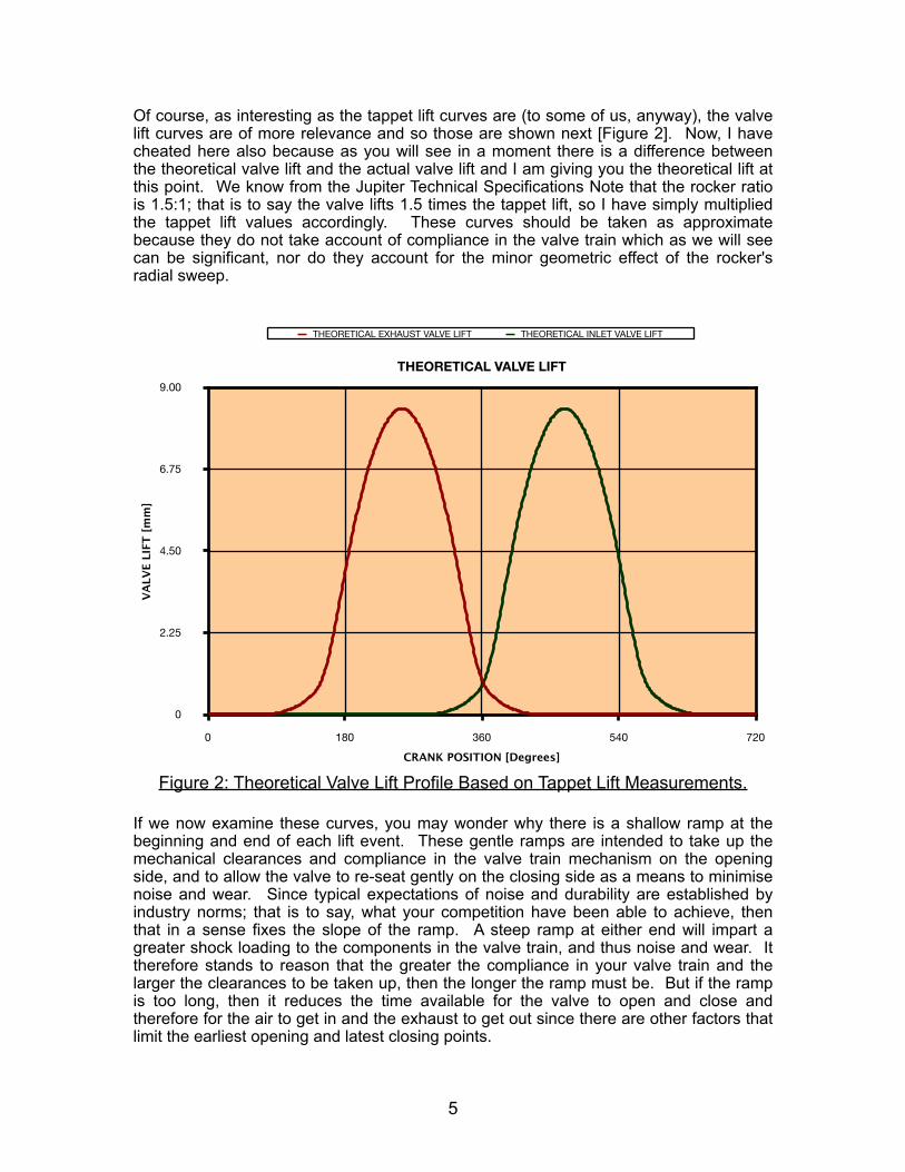
There is a metric called KLD that illustrates this effect [Figure 3]. If one were to draw a rectangular box of height "L" [= valve lift] and length "D" [= lift duration] and then overlay that with the valve lift diagram, you would observe that the area described by the valve event is much less than the area of the rectangle. This is obviously so since the valve cannot be made to immediately go to full lift, stay there, and then drop instantaneously to closed. So, in a high performance pushrod engine with aggressive profiles (think NASCAR), the KLD factor is around 50%; that is to say, the valve event area is about 50% of the ideal. Based on the valve lift curves for the Jowett engine, our KLD ratio is about 39% which means that we are missing out on breathing potential mainly due to valve train compliance. If Jowett had been able to specify a more aggressive profile to give a higher KLD and thus more performance, they would have done so, but without a significantly different engine architecture they could not.
Figure 3: Jowett Cam Profile KLD: The Area Under the Theoretical Lift Curve (Cross-hatched) is 39% of the Box Area, (and Even Less Than That in a Real Engine).
6
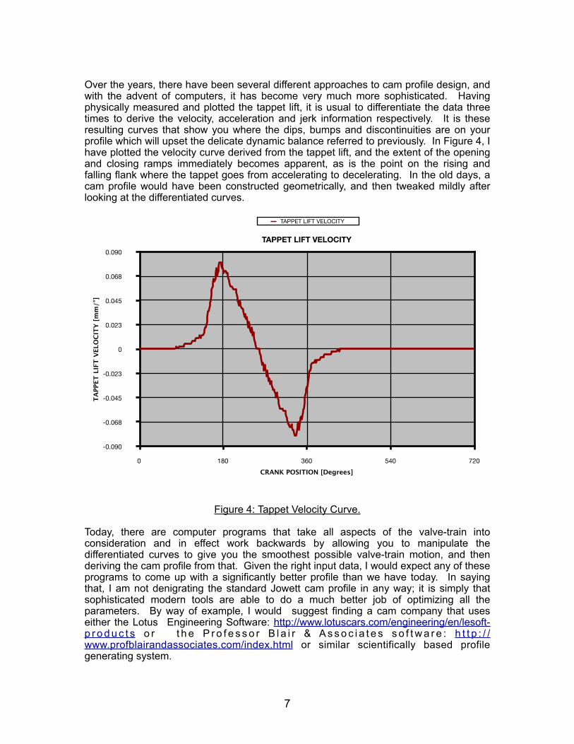
Over the years, there have been several different approaches to cam profile design, and with the advent of computers, it has become very much more sophisticated. Having physically measured and plotted the tappet lift, it is usual to differentiate the data three times to derive the velocity, acceleration and jerk information respectively. It is these resulting curves that show you where the dips, bumps and discontinuities are on your profile which will upset the delicate dynamic balance referred to previously. In Figure 4, I have plotted the velocity curve derived from the tappet lift, and the extent of the opening and closing ramps immediately becomes apparent, as is the point on the rising and falling flank where the tappet goes from accelerating to decelerating. In the old days, a cam profile would have been constructed geometrically, and then tweaked mildly after looking at the differentiated curves.
Figure 4: Tappet Velocity Curve.
Today, there are computer programs that take all aspects of the valve-train into consideration and in effect work backwards by allowing you to manipulate the differentiated curves to give you the smoothest possible valve-train motion, and then deriving the cam profile from that. Given the right input data, I would expect any of these programs to come up with a significantly better profile than we have today. In saying that, I am not denigrating the standard Jowett cam profile in any way; it is simply that sophisticated modern tools are able to do a much better job of optimizing all the parameters. By way of example, I would suggest finding a cam company that uses either the Lotus Engineering Software: http://www.lotuscars.com/engineering/en/lesoft-p r o d u c t s o r t h e P r o f e s s o r B l a i r & A s s o c i a t e s s o f t w a r e : h t t p : / /www.profblairandassociates.com/index.html or similar scientifically based profile generating system.
7
-0.090
-0.068
-0.045
-0.023
0
0.023
0.045
0.068
0.090
0 180 360 540 720
TAPPET LIFT VELOCITY
TAPP
ET L
IFT
VELO
CITY
[mm
/°]
CRANK POSITION [Degrees]
TAPPET LIFT VELOCITY
I should note at this point that previously, I had carefully inspected the camshaft including measuring the journals and confirmed that it was a good item. I even made a drawing of it (see below), but when I assembled the camshaft into the crankcase I discovered that although there was no vertical motion, there was 0.004" (0.100 mm) free play side to side at the front journal. I did not check the other journals, but assume that they were the same. I also noted that in moving the camshaft side to side by hand, the crankcase made a loud ringing noise. Now why would a line-bored hole be so obviously oval? I suppose it could have worn that way, but there was no indication of oil starvation or distress of the bearing surfaces so I am inclined to reject that theory. Now it so happens that this engine (No. E3 SCL 987) has mismatched crankcase halves (L/H = 25884, R/H = 91166), and the crankcase obviously at one time had one of those "Rebuilt" engine plates on it. I think that Jowett Engineering Ltd. overlooked the camshaft journal issue when they built up this engine from available parts and at least one of the halves was bored off-center, resulting in this bearing ovality.
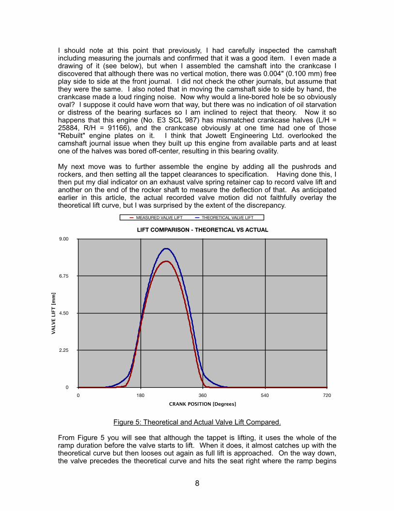
My next move was to further assemble the engine by adding all the pushrods and rockers, and then setting all the tappet clearances to specification. Having done this, I then put my dial indicator on an exhaust valve spring retainer cap to record valve lift and another on the end of the rocker shaft to measure the deflection of that. As anticipated earlier in this article, the actual recorded valve motion did not faithfully overlay the theoretical lift curve, but I was surprised by the extent of the discrepancy.
Figure 5: Theoretical and Actual Valve Lift Compared.
From Figure 5 you will see that although the tappet is lifting, it uses the whole of the ramp duration before the valve starts to lift. When it does, it almost catches up with the theoretical curve but then looses out again as full lift is approached. On the way down, the valve precedes the theoretical curve and hits the seat right where the ramp begins
8
0
2.25
4.50
6.75
9.00
0 180 360 540 720
LIFT COMPARISON - THEORETICAL VS ACTUAL
VALV
E LI
FT [m
m]
CRANK POSITION [Degrees]
MEASURED VALVE LIFT THEORETICAL VALVE LIFT
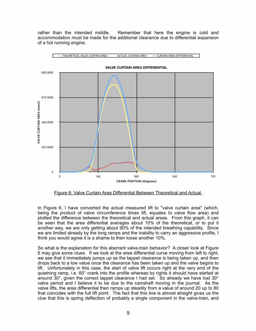
rather than the intended middle. Remember that here the engine is cold and accommodation must be made for the additional clearance due to differential expansion of a hot running engine.
Figure 6: Valve Curtain Area Differential Between Theoretical and Actual.
In Figure 6, I have converted the actual measured lift to "valve curtain area" (which, being the product of valve circumference times lift, equates to valve flow area) and plotted the difference between the theoretical and actual areas. From this graph, it can be seen that the area differential averages about 10% of the theoretical, or to put it another way, we are only getting about 90% of the intended breathing capability. Since we are limited already by the long ramps and the inability to carry an aggressive profile, I think you would agree it is a shame to then loose another 10%.
So what is the explanation for this aberrant valve-train behavior? A closer look at Figure 6 may give some clues. If we look at the area differential curve moving from left to right, we see that it immediately jumps up as the tappet clearance is being taken up, and then drops back to a low value once the clearance has been taken up and the valve begins to lift. Unfortunately in this case, the start of valve lift occurs right at the very end of the quietning ramp, i.e. 60° crank into the profile whereas by rights it should have started at around 30°, given the correct tappet clearance I had set. So already we have lost 30° valve period and I believe it to be due to the camshaft moving in the journal. As the valve lifts, the area differential then ramps up steadily from a value of around 20 up to 80 that coincides with the full lift point. The fact that this line is almost straight gives us the clue that this is spring deflection of probably a single component in the valve-train, and
9
0
225.0000
450.0000
675.0000
900.0000
0 180 360 540 720
VALVE CURTAIN AREA DIFFERENTIAL
VALV
E CU
RTA
IN A
REA
[mm
2]
CRANK POSITION [Degrees]
THEORETICAL VALVE CURTAIN AREA ACTUAL CURTAIN AREA CURTAIN AREA DIFFERENTIAL
my guess is the rocker shaft. Just after turning the corner to head back down, the trace takes an ugly turn for the worse as something in the valve-train shifts unexpectedly again. As a result, the valve closes much sooner than it should and with a seating velocity far higher than is intended. Thus we have lost another 30° at the back end of the lift trace and can predict a noisy engine with high valve-train wear rates.
What this study points up is the importance of camshaft bearing clearance to the Jowett engine. Because our engine has a horizontally opposed format and a single central camshaft, the tappets approach the camshaft in near horizontal opposition too. In fact, the included angle between them is not 180° as for the cylinders, but 155° which is still close enough to being opposed. As a result, there is a constantly varying side thrust on the camshaft that alternates from side to side and location along the length of the camshaft depending upon the instantaneous valve spring force balance as the camshaft rotates through each revolution. Our engine is particularly sensitive in this respect since any play or slop in the camshaft bearings will result in the characteristics seen in Figure 6. This is not the case in conventional inline engines since all the tappet forces react in one direction only [downward].
Thus in our case if there is any free play, the camshaft will move from side to side in its bearing bores depending upon which springs are being compressed at that particular moment. Essentially, it is a balance of forces, and the stronger force wins. It is this that accounts for the two big jumps in Figure 6 and the resulting loss in valve event duration relative to the theoretical curve. Notably, the Workshop Manual indicates an acceptable wear level of up to 0.003" [0.076 mm] on the camshaft journals, but of course it is the combined wear of journals and bearing bores which is the important parameter. However, based on what I have observed here, I would cut that tolerance in half for any engine that was being rebuilt for either performance or long life.
In summary then, the results that I have reported here are probably at the bad end of the spectrum because of the excessive sideways slop of the camshaft in its bearings in this instance; your engine may not be as bad. Nevertheless, this emphasizes how critical cam bearing clearance is for any Jowett engine that is receiving a complete and expensive overhaul.
That of course brings up the question of how to identify the problem and what to do about it. Ideally, one should look for this problem during a trial assembly after the crankcase and camshaft have been cleaned and inspected but before final assembly so that one has more options for corrective action. Once the engine has been half assembled, there is an understandable reluctance to take it apart for rectification. I measured the slop by placing a dial indicator against the camshaft as I moved it side-to-side by hand. If the bearing bores are good but the camshaft has worn undersize, then possibly building up the camshaft journals with a coating or plating may be a solution. If as in this case, it is the crankcase bearing bores that are worn oversize or oval, then they will need to be line bored and perhaps fitted with bearing shells as for the crankshaft mains, but with a 1.500" ID.
Of course, if you have line bored the camshaft bearings to an oversize, this could give you the excuse to manufacture a new camshaft altogether that exploits the newly enlarged OD by providing cams with slightly higher lift.
Returning to the hypothesis of rocker shaft deflection suggested above, I ran a further test to explore this issue. Many other people have observed this feature on other OHV engines and have devised techniques to mitigate the problem. Essentially, designing a rocker shaft that overhangs the support pedestal was a cheap solution for low
10
performance engines, and by the 1950's it should have been obsolete but its low cost maintained its appeal for mass produced engines.
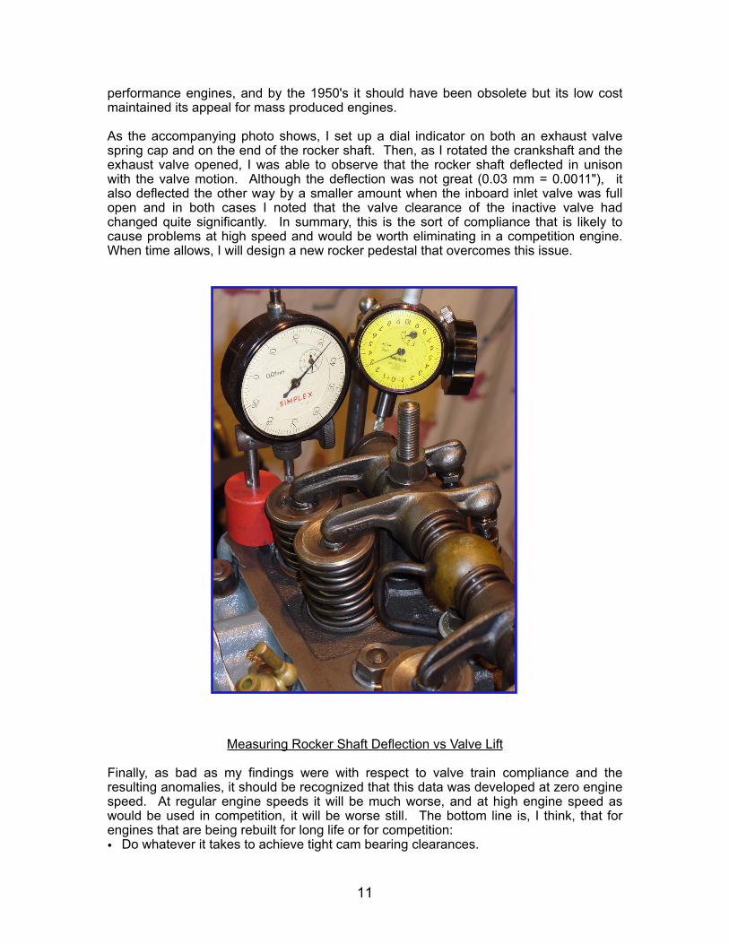
As the accompanying photo shows, I set up a dial indicator on both an exhaust valve spring cap and on the end of the rocker shaft. Then, as I rotated the crankshaft and the exhaust valve opened, I was able to observe that the rocker shaft deflected in unison with the valve motion. Although the deflection was not great (0.03 mm = 0.0011"), it also deflected the other way by a smaller amount when the inboard inlet valve was full open and in both cases I noted that the valve clearance of the inactive valve had changed quite significantly. In summary, this is the sort of compliance that is likely to cause problems at high speed and would be worth eliminating in a competition engine. When time allows, I will design a new rocker pedestal that overcomes this issue.
Measuring Rocker Shaft Deflection vs Valve Lift
Finally, as bad as my findings were with respect to valve train compliance and the resulting anomalies, it should be recognized that this data was developed at zero engine speed. At regular engine speeds it will be much worse, and at high engine speed as would be used in competition, it will be worse still. The bottom line is, I think, that for engines that are being rebuilt for long life or for competition:• Do whatever it takes to achieve tight cam bearing clearances.
11
• Find ways to improve the rocker shaft stiffness to minimize deflection at that location. • If you elect to have a new camshaft made or an existing shaft re-profiled, don’t accept
an existing profile that was developed for a totally different engine; that is old-school. Use an Industry-recognized computer program and take some of the values that I have reported here for component mass and spring forces and let the program derive a new profile that is specific for our situation. Then share the design with the rest of the Jowett community.
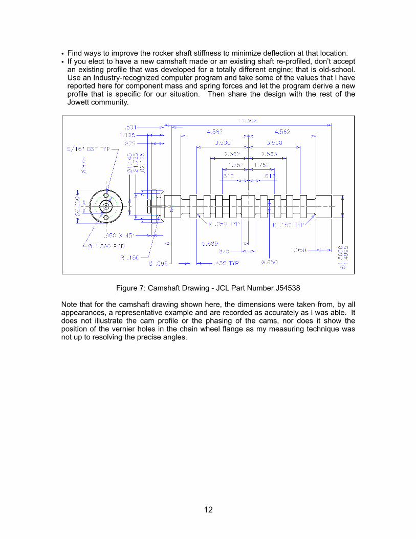
Figure 7: Camshaft Drawing - JCL Part Number J54538
Note that for the camshaft drawing shown here, the dimensions were taken from, by all appearances, a representative example and are recorded as accurately as I was able. It does not illustrate the cam profile or the phasing of the cams, nor does it show the position of the vernier holes in the chain wheel flange as my measuring technique was not up to resolving the precise angles.
12