a design scheme of steel connections for … · a design scheme of steel connections for preventing...
TRANSCRIPT

1223
1 Department of Architecture, Chiba University, Chiba, Japan. E-mail: [email protected] Department of Architecture, Chiba University, Chiba, Japan. E-mail: [email protected] Technical Development Bureau, Nippon Steel Corporation, Futtsu, Chiba, Japan. E-mail: [email protected] Structural Research Laboratories,Kawasaki Steel Corporation, Chiba, Japan. E-mail: [email protected]
A DESIGN SCHEME OF STEEL CONNECTIONS FOR PREVENTING BRITTLEFRACTURE
Koichi TAKANASHI1, Koji MORITA2, Takahiko SUZUKI3 And Takumi ISHII4
SUMMARY
After 1994 Northridge and 1995 Hyougoken-nanbu earthquakes, a great deal of experimentalworks have been carried out. We have been able to have ample knowledge from the experimentsas well as many findings among literatures in the fracture mechanics field. The authors propose, inthis paper, a design scheme to produce reliable connections even under severe earthquakes. Theremight be many factors controlling the initiation of fracture. Among them major factors must be thefracture toughness of steels, the sizes and the shapes of notches and the strain concentration aroundthe notches. From the practical viewpoint of design, however, most of the factors are not beenclearly aware to designers beforehand. Only an exception is the fracture toughness of the steels.The structural designers can choose suitable steels with the adequate fracture toughness. Here, theauthors take a typical type of welded connection of a square hollow section column and H-shapedbeams, which is widely used in Japan. And we assume the connection is well fabricated followingthe recommended details and welding procedure. Under these limited application though, utilizingknowledge on the fracture toughness develops the design scheme. The adequacy of the scheme isexamined comparing with the experimental results.
INTRODUCTION
After two severe earthquakes, a great deal of tests has been carried out. We learned many factors, which maycause fracture of steel structures, particularly fracture around welded connections. In addition, we found manyachievements on the fracture problem among literatures in the fracture mechanics field. Nevertheless, very fewpapers discussed how to design welded connections avoiding the premature fracture during earthquakes. Theauthors try, in this paper, to demonstrate a design way in order to realize a reliable connection utilizingknowledge from past experiments. They are aiming at a practical design way for practitioners’ use.
2. DESIGN PROCEDURE PROPOSED
2.1 Required Ductility
It is widely known in the seismic design that structures must absorb the input energy due to a severe earthquakeby converting it into the plastic strain energy. Therefore, the structure must have enough deformation capacity(ductility). In the design procedure, structural designers first want to know how much the structure be expectedto have it. The recent dynamic analysis of medium-rise moment frames shows us the required amount ofductility under a specified intensity of earthquake motion[ Inoue et al. 1999]. Fig.1 shows its typical results. Therequired rotation angles of the beams are presented against the maximum values of the pseudo-velocities ofearthquake motions. The columns are assumed to be within the elastic limit in the analysis. The yield strength ofthe frames is set to be 0.3 of the maximum elastic response as the base shear forces. We can know the requiredvalue of rotation angle of the beams for a specified intensity of the seismic load and utilize it for design of thebeam-to-column connections.

12232
Figure 1: Required rotation angle of beam vs. pseudo-velocity of earthquake motion
2.2 Beam-to-Column Connections for Design
The connection discussed in this paper is limited to the connection of a square hollow section column and a H-shaped section beam. A typical type of the connection is shown in Fig.2, which is widely used in the momentframes in Japan. The flange plates of the beam are welded to the through diaphragms crossing the columnsection, while the web plate of the beam is welded or bolted to the column surface. Our problem is how to designa reliable weld joint of the flange. For this purpose, we must first evaluate accurately the flange force, which isacting on the weld joint, associated with the required rotation angle of the beam. The evaluation needs the plasticanalysis taking into account a non-effective region of the web plate. The results of the analysis are presented inFig.3. The maximum flange force Pf in the vertical axis, as expressed in a non-dimensional form, Pf / Pu ( Pu=�u Af: �u = the tensile strength of the steel, Af = the section area of a flange), can be evaluated according to therequired rotation angle �bp in the horizontal axis, depending on the yield ratio YR of the steel. The detail of theanalysis is described in Appendix II.
Figure 2: Typical type of beam-to-column Figure 3: Flange force vs. plastic end rota-connections tion angle of beam relationships
2.3 Expected Strength of Weld Joint
In the preceding articles, it is shown to be possible to evaluate the rotation angle required for resisting against aspecified level of earthquake intensity, and then the flange force acting on the weld joint associated with therequired rotation angle. The strength of the weld between the flange and the diaphragm must be greater than theflange force as far as possible. It is well known that the weld strength is influenced with the quality of weld,fabrication and steel, the base metal. As the quality of the weld and the fabrication is much depending on thedetailing of connection and fabrication procedure, the authors assume that designers choose a preferableconnection details as shown in Fig.A1.2(b) in Appendix I, where a connection detail was selected among severalother details, referring to the performance examined in the experiments. These connection details in Appendix Imust be fabricated under the well-controlled procedure. Thus, the authors can focus their discussions on thefactor left, the quality of steels.
12233
It is known that the fracture toughness of the steel is the most important factor controlling the premature fracture.The authors carried out recently a series of tension tests on the specimens including the weld joint. A surfacenotch is intentionally provided at the end of the weld bead. The test parameters are the quality of steels, the sizeof the notch, the loading speed and the test temperature. These will affect the fracture toughness of thespecimens. The fracture toughness was evaluated by the Charpy V-notch test. The energy absorption measuredin the Charpy test is considered as an efficient index to indicate the fracture toughness, in spite that the Charpytest is easily conducted in a relatively low cost. The test is described more in detail in Appendix III.
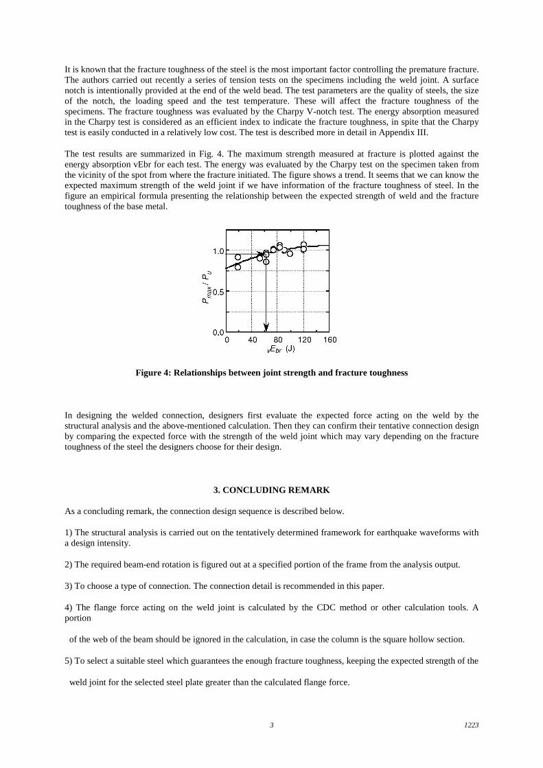
The test results are summarized in Fig. 4. The maximum strength measured at fracture is plotted against theenergy absorption vEbr for each test. The energy was evaluated by the Charpy test on the specimen taken fromthe vicinity of the spot from where the fracture initiated. The figure shows a trend. It seems that we can know theexpected maximum strength of the weld joint if we have information of the fracture toughness of steel. In thefigure an empirical formula presenting the relationship between the expected strength of weld and the fracturetoughness of the base metal.
Figure 4: Relationships between joint strength and fracture toughness
In designing the welded connection, designers first evaluate the expected force acting on the weld by thestructural analysis and the above-mentioned calculation. Then they can confirm their tentative connection designby comparing the expected force with the strength of the weld joint which may vary depending on the fracturetoughness of the steel the designers choose for their design.
3. CONCLUDING REMARK
As a concluding remark, the connection design sequence is described below.
1) The structural analysis is carried out on the tentatively determined framework for earthquake waveforms witha design intensity.
2) The required beam-end rotation is figured out at a specified portion of the frame from the analysis output.
3) To choose a type of connection. The connection detail is recommended in this paper.
4) The flange force acting on the weld joint is calculated by the CDC method or other calculation tools. Aportion
of the web of the beam should be ignored in the calculation, in case the column is the square hollow section.
5) To select a suitable steel which guarantees the enough fracture toughness, keeping the expected strength of the
weld joint for the selected steel plate greater than the calculated flange force.

12234
ACKNOWLEDGEMENTS
The authors research has been conducted under General Technology Development Project of the Ministry ofConstruction entitled Development of Structural Safety Improvement Technology Utilizing New GenerationSteel. The authors wish to express their sincere gratitude to all researchers involved in the Project.
REFERENCES
Inoue et al. (1999),” Ductility demanded of members in steel moment frames sustaining beam-hingingmechanism 1~6 ”, Proceedings AIJ Annual Convention ( to be published )
Bennet,P.E. and Sinclair,G.M. (1966),” Parameter Representation of Low-temperature Yield Behavior of Body-centered Cubic Transition Metals, “ Transaction ASME, pp518-524.
Appendix I A typical beam-to-column connection and the recommended detail of weld joint
More than 90% of steel buildings are less than 5 story buildings. The structural configuration of these buildingsis in general the resistant moment frame which is composed of square hollow section columns and H-shapebeams. A typical connection in the frame is as shown in Fig.A1.1. The flange plates of the beam are welded tothe edge of the through diaphragm crossing the column section. There are some details used in practice forwelding the flange to the diaphragm as shown in Fig.A1.2. The details are characterized by the shape of the weldaccess hole and the location of weld fixing the backing bar at the right position. One of the authors conductedcyclic bending tests on the T-type beam-to-column connections which have the different types of welded jointdetails. The results show various behavior. Some were easily ruptured in a few cycles, but some were welldeformed without premature fracture. A joint detail to be recommended is one in Fig.A1.2(b). In fact, thespecimen with this type of detail shows a good structural performance as shown in Fig.A1.3. We can expectenough ductility in this connection.
Note Electrodes: YGW11 mm YGW18 1.4mm Heat input: 25-30kJ/cmInter pass temperature: less than 300oC
Figure A1.1: Specimen configuration and loading condition

12235
Figure A1.2: Detail of joint
Figure A1.3: Beam end moment vs. relative rotationof beam end connection relationship
Appendix II Relationship between Flange Force and End Rotation Angle of a Beam

12236
The Column Deflection Method (CDC method) can calculate the relationship between the flange force and theend rotation angle of a beam. A portion of the web is ignored as shown in Fig.A2.1, according to the evidence inthe stress distribution of the web in the vicinity of the column surface of square hollow section. The relationshipobtained as shown in Fig.A2.2 is depending also on the yield ratio YR of the steel. In the figure, the end rotationangle is denoted as �bp in the horizontal axis and the flange force Pf in the vertical axis is expressed in a non-dimensional form as Pf / Pu, where Pu = �u�Af, �u = the tensile strength, Af = the section area of a flange.The calculation result is verified by the experiments conducted by the authors.
Figure A2.1: Configuration of CDC method model
Figure A2.2: Flange force vs. plastic end rotation angle relationships
Appendix III Tension Tests on Welded Joints
The tension tests were conducted on the welded joint as shown in Fig.A3.1. The weld joint is centered in thespecimen. The left part of the weld is regarded as the through diaphragm, while the right part is regarded as theflange plate. The right part is so tapered that the stress distribution is gradually changing just as the stress in theflange induced due to bending moment. A surface notch was intentionally provided at the end of weld bead asshown in Fig.A3.2. The depth of the notch varies from 3 ~ 25 mm and the length from 3 ~ 40 mm. The detail ofweld joint is illustrated in Fig.A3.3, where the groove preparation of a single bevel groove weld such as the rootopening and the groove angle is also shown. The weld was made by the CO2 gas shielded metal arc. Otherwelding conditions are shown in the figure.
The other test parameters are the quality of the steel, the loading speed and the test temperature: The specimenswere made of two kinds of steels; a high toughness steel and a low toughness steel. The yield ratios of the steelsdiffer a little. In order to examine the effect of the loading speed on fracture, the tests were conducted under thehigh speed loading, say, 300 mm /sec of the ram speed and the quasi-static loading. The test temperature must bea very important parameter in the fracture tests. In these tests, the temperature was carefully kept at specifiedtemperatures, that is, 0, -20, -40 degree in the centigrade. The effect of the strain-rate and the temperature on thestrength of steels can be comprehensively expressed in empirical formulas using the strain rate-temperatureparameter R [Bennet and Sinlair, 1966]. Following these formulas, the strength of the steels used in the tests wasuniformly evaluated. Fig.A3.4 demonstrates good coincidence in the stress-strain curves between the evaluatedvalues and the experimental results. The tensile strength of the plate of each specimen, Pu, was calculated fromthe evaluated value of steel strength.

12237
The fracture toughness was evaluated by the Charpy V-notch test and expressed as the absorption energy. Thespecimens for the Charpy test were taken from the vicinity of the spot from where the fracture initiated. Theresults of the tension tests are summarized in Fig.A3.5. The recorded ultimate strength Pmax, in the non-dimension form, Pmax / Pu, is plotted against the measured energy absorption vEbr. In spite that there wereseveral sizes of notches in the specimens, the data are scattered in a rather narrow band. The regression formulawas made and illustrated in the figure. It seems that we can guess the expected strength of weld joints, providedthe fracture toughness of the steel to be used is known.
Figure A3.1: Specimen configuration of tension test
Figure A3.2: Location of defect Figure A3.3: Detail of joint and welding condition
Figure A3.4: Stress-strain models Figure A3.5: Joint strength vs. fracturetoughness relationships