a cryogenics company - cpc-cryolabcpc-cryolab.com/pdffiles/rockwood-swendeman catalog...
TRANSCRIPT
A CRYOGENICS COMPANY
®

Air Liquide America, Houston, Texas, has standardizedthe Rockwood Swendeman CryoTree™
assembly as part of their ongoing cost reduction programs to serve customers moreeffectively. Air Liquide has stated that although the total cost of the Rockwood SwendemanCyroTree™ parallels their internal fabricated designused in the past, their fabrication time can now bespent in other areas. Originally five to six separate purchase orders were issued for individualcomponents. It now requires only one. This modular design provides only two
part numbers for their complete tank inventory providing standardization
on a global basis.
RockwoodSwendemancan provide
you with reliable, highquality safety
relief valves, atthe most
competitiveprice in the
industry andour lead time
on mostorders is threeweeks or less.
QUALITY PRICE LEAD TIME
845.778.5566 • www.rockwoodswendeman.com • Fax 845.778.1072

– 1 –
A CRYOGENICS COMPANY
Rockwood Swendeman valves are guaranteed against defects in material or workmanship for aperiod of one year. Any valve claimed to be defective may be returned to us, on receipt of our
written consent, for examination. If in our opinion the valve is defective it will be repaired or replaced F.O.B. our plant. Under no circumstances does Rockwood Swendeman assume
responsibility for consequential damages, labor, repair or other expenses.
Any adjustments or repairs should be done by Rockwood Swendeman at our facility. We have 50 plus years experience as a world leader in the manufacture and
assembly of reliable safety relief valves for the industrial gas industry. Today many multi-national firms in the industry rely on quality Rockwood Swendeman valves. We manufacture
bronze and stainless steel valves for air, gas and liquid service.
Designed and manufactured with a commitment to quality and servicewith over 50 years of experience in the cryogenic and gas industry.
TUVANLAGEN UNO UMWELT
AARAAAARR� �
visit our website at: www.rockwoodswendeman.com
®
845.778.5566 • www.rockwoodswendeman.com • Fax 845.778.1072
– 2 –
CRYOGENICS COMPANYA
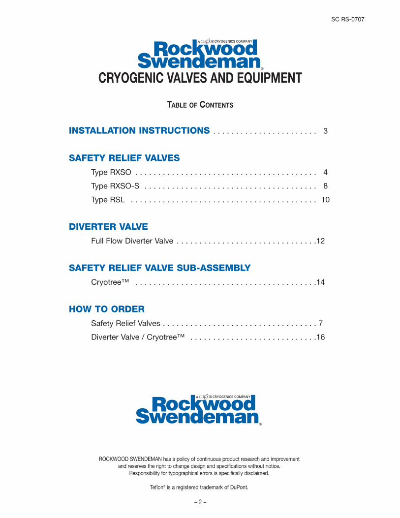
CRYOGENIC VALVES AND EQUIPMENT
TABLE OF CONTENTS
ROCKWOOD SWENDEMAN has a policy of continuous product research and improvement and reserves the right to change design and specifications without notice.
Responsibility for typographical errors is specifically disclaimed.
Teflon® is a registered trademark of DuPont.
INSTALLATION INSTRUCTIONS . . . . . . . . . . . . . . . . . . . . . . . 3
SAFETY RELIEF VALVES
Type RXSO . . . . . . . . . . . . . . . . . . . . . . . . . . . . . . . . . . . . . . . . 4
Type RXSO-S . . . . . . . . . . . . . . . . . . . . . . . . . . . . . . . . . . . . . . 8
Type RSL . . . . . . . . . . . . . . . . . . . . . . . . . . . . . . . . . . . . . . . . . 10
DIVERTER VALVE
Full Flow Diverter Valve . . . . . . . . . . . . . . . . . . . . . . . . . . . . . . .12
SAFETY RELIEF VALVE SUB-ASSEMBLY
Cryotree™ . . . . . . . . . . . . . . . . . . . . . . . . . . . . . . . . . . . . . . . .14
HOW TO ORDER
Safety Relief Valves . . . . . . . . . . . . . . . . . . . . . . . . . . . . . . . . . . 7
Diverter Valve / Cryotree™ . . . . . . . . . . . . . . . . . . . . . . . . . . . .16
CRYOGENICS COMPANYA
SC RS-0707

– 3 –
PHONE: (845) 778-5566 FAX: (845) 778-1072
Rockwood Swendeman Pressure Relief valves are safety devices designed to protect pressurized vessels, lines or systems during an overpressure event. The recommendationsbelow are general and it is the responsibility of the user to assure that installation and maintenance are in accordance with the applicable ASME Codes and local requirements. Neither Rockwood Swendemannor its agents assume any liability for valvesimproperly installed or maintained. AlternateEuropean languages per Directive 97/23/EC(PED) are available through our website www.rockwoodswendeman.com.
GENERAL RECOMMENDATIONSIt is solely the responsibility of the systemdesigner and the user to select products andmaterials suitable for their specific applicationrequirements (including but not limited to setpressure/temperature and fluid service) and to ensure proper installation, operation, andmaintenance of these products. See ProductGuide for applicable pressure/temperature limits. Assistance shall be afforded with theselection of the materials based on the technical information supplied to SpenceEngineering Co. Applicable codes, materialcompatibility, product ratings and applicationdetails should be considered in the selectionand application. Improper selection, application or use of the pressure relief valvecan cause personal injury or property damage.If the product is intended for an application oruse other than originally specified, the systemdesigner and or user must reconfirm that theselection is suitable for the new operating conditions.
INSTALLATION1. Qualified service personnel must perform
installation only. 2. Valves must be installed in an upright
vertical position with the spindle vertical. 3. The connection to the vessel should be
provided with a radius to permit smoothflow to the valve.
4. Do not place any block valves or checkvalves between pressure vessel and safetyrelief valve.
5. Make sure the system is clean and free of any dirt, sediment or scale that mightbecome lodged on the valve seat.
6. Use a minimum amount of thread sealantor tape on inlet thread. Tighten valve usingthe proper wrench on the hex flats of thevalve base. Do not use excessive forceduring tightening.
7. The opening through all pipe and fittingsbetween the pressure vessel and the valvemust be at least the same area as therelief valve inlet.
8. Discharge piping shall be at least the samesize as the pressure relief valve outlet. Thedischarge piping should be anchored toprevent any swaying or vibration while thevalve is discharging.
9. CAUTION: The piping system must beadequately designed and supported toprevent extraordinary loads to the pressureequipment.
MAINTENANCE1. Valves are set and sealed to prevent
tampering. If wire seal is broken, the valve is unsafe and should not be used.Guarantee is void if any seal is broken.
2. The valves should be checked periodicallyto see that they are not clogged or seizeddue to dirt or other foreign matter and thatthey will operate satisfactorily.
3. WARNING: Operation of valve involves the discharge of high-pressure cryogenic fluids. Suitable hearing protection shouldbe worn and hands must be kept awayfrom discharge.
4. The setting adjustment or repair should bedone only by an authorized repair facility.
5. WARNING: Injury or death can occur dueto failure to completely isolate valve fromall sources of pressure before beginningdisassembly. Do not proceed until valvehas been completely isolated from processstream and vented to atmosphere.
6. Only original, unmodified RockwoodSwendeman parts should be used toassure safe and proper operation.
CRYOGENICS COMPANYA

CRYOGENICS COMPANYA
– 4 –
®
Features
• Special Teflon® seat, making bubble-tightseals possible to over 90% of setpressures per spec API 527; notapplicable to steam.
• Adjustable blowdown ring• Meets AD-Merkblatt A2 certified by • Cleaned and packaged for use in O2
service in compliance with the CGA specification G-4.1
Additional cleaning specifications: • 4WPI-SW70003 • ES.660.503• GS-38 • GS-40
Application• Especially recommended where noxious
or expensive liquids or gases place apremium on seal quality.
• Stationary Cryogenic storage tanks• Dual Safety relief systems• Overpressure relief of tanks, pipelines,
vessels, pumps• Air and gas compressors• Corrosive industrial applications
Options• Large and Extra Large Capacity
Consult factory for flow rates• BSP threads are available on most sizes• Lever operation
Technical Data
Operating RangesTemperature ……………-423ºF to +400˚FSet Pressures ……………to 400 psig
Materials of ConstructionShell ………………………Cast Bronze,
A.S.M.E SB-62Base ………………………Forged Brass,
Alloy C37700Trim ………………………Copper AlloySpring ……………………Stainless Steel
17-7 PH A.S.T.M.,A-313, Type 631
TestsEach valve is set, tested, retested and sealed atthe factory to the customer’s specifications.
SizesInlet - 1/2 inch to 2 inchOutlet - 3/4 inch to 2-1/2 inch
Applicable Codes
Designed and manufactured to meet:• CGA S-1.2 and S-1.3.• V-4301 (Cryogenic Non-Oxygen)• V-4401 (Oxygen)• ASME sec.VIII• API 527• AD-Merkblatt A2• CRN 0G0591.9
BRONZESAFETY RELIEF VALVES
TYPE RXSO0 - 400 psig

Type RXSODimensions & CharacteristicsAIR CAPACITY TABLEDischarge capacities in cubic feet per minute of air at 10% or 3 PSI, whichever is greater, overpressure.
– 5 –
Inlet Sizes 1/2 3/4 1 1-1/4
Inches 1/2 3/4 1 1-1/4 1-1/23/4 1 1-1/4 1-1/2 2
Outlet Sizes 3/4 1 1-1/4 1-1/2 21 1-1/4 1-1/2 2 2-1/2
Seat Diameter A B C D E0.750 1.000 1.250 1.500 2.000
Flow Area 0.118 0.204 0.326 0.424 0.628Set Pressure
10 36 63 100 130 19315 43 74 118 154 22720 48 85 136 177 26225 55 96 154 200 29730 62 108 172 224 33235 70 120 192 250 37040 77 133 212 276 40845 84 145 232 301 44650 91 157 252 327 48555 98 170 271 353 52360 105 182 291 379 56165 113 195 311 405 59970 120 207 331 430 63875 127 220 351 456 67680 134 232 371 482 71485 141 244 391 508 75290 149 257 410 534 79195 156 269 430 560 829100 163 282 450 585 867105 170 294 470 611 905110 177 307 490 637 944115 184 319 510 663 982120 192 331 530 689 1020125 199 344 549 715 1058130 206 356 569 740 1097135 213 369 589 766 1135140 220 381 609 792 1173145 228 393 629 818 1211150 235 406 649 844 1249155 242 418 668 869 1288160 249 431 688 895 1326165 256 443 708 921 1364170 264 456 728 947 1402175 271 468 748 973 1441180 278 480 768 999 1479185 285 493 788 1024 1517190 292 505 807 1050 1555195 299 518 827 1076 1594200 307 530 847 1102 1632205 314 543 867 1128 1670
Inlet Sizes 1/2 1/2 3/4 1 1-1/4
Inches 3/4 3/4 1 1-1/4 1-1/21 1-1/4 1-1/2 2
Outlet Sizes 3/4 1 1-1/4 1-1/2 21 1-1/4 1-1/2 2 2-1/2
Seat Diameter A B C D E0.750 1.000 1.250 1.500 2.000
Flow Area 0.118 0.204 0.326 0.424 0.628Set Pressure
210 321 555 887 1153 1708215 328 567 907 1179 1747220 335 580 927 1205 1785225 343 592 946 1231 1823230 350 605 966 1257 1861235 357 617 986 1283 1900240 364 629 1006 1308 1938245 371 642 1026 1334 1976250 378 654 1046 1360 2014255 386 667 1066 1386 2053260 393 679 1085 1412 2091265 400 692 1105 1437 2129270 407 704 1125 1463 2167275 414 716 1145 1489 2206280 422 729 1165 1515 2244285 429 741 1185 1541 2282290 436 754 1204 1567 2320295 443 766 1224 1592 2359300 450 779 1244 1618 2397305 458 791 1264 1644 2435310 465 803 1284 1670 2473315 472 816 1304 1696 2511320 479 828 1324 1721 2550325 486 841 1343 1747 2588330 493 853 1363 1773 2626335 501 866 1383 1799 2664340 508 878 1403 1825 2703345 515 890 1423 1851 2741350 522 903 1443 1876 2779355 529 915 1463 1902 2817360 537 928 1482 1928 2856365 544 940 1502 1954 2894370 551 952 1522 1980 2932375 558 965 1542 2005 2970380 565 977 1562 2031 3009385 990 989 1582 2057 3047390 580 1002 1602 2083 3085395 587 1015 1621 2109 3123400 594 1027 1641 2135 3162
TO ORDER: See Page 7
Note: Pressure Settings below 15psig (1.034 barg) are non code.
– 6 –
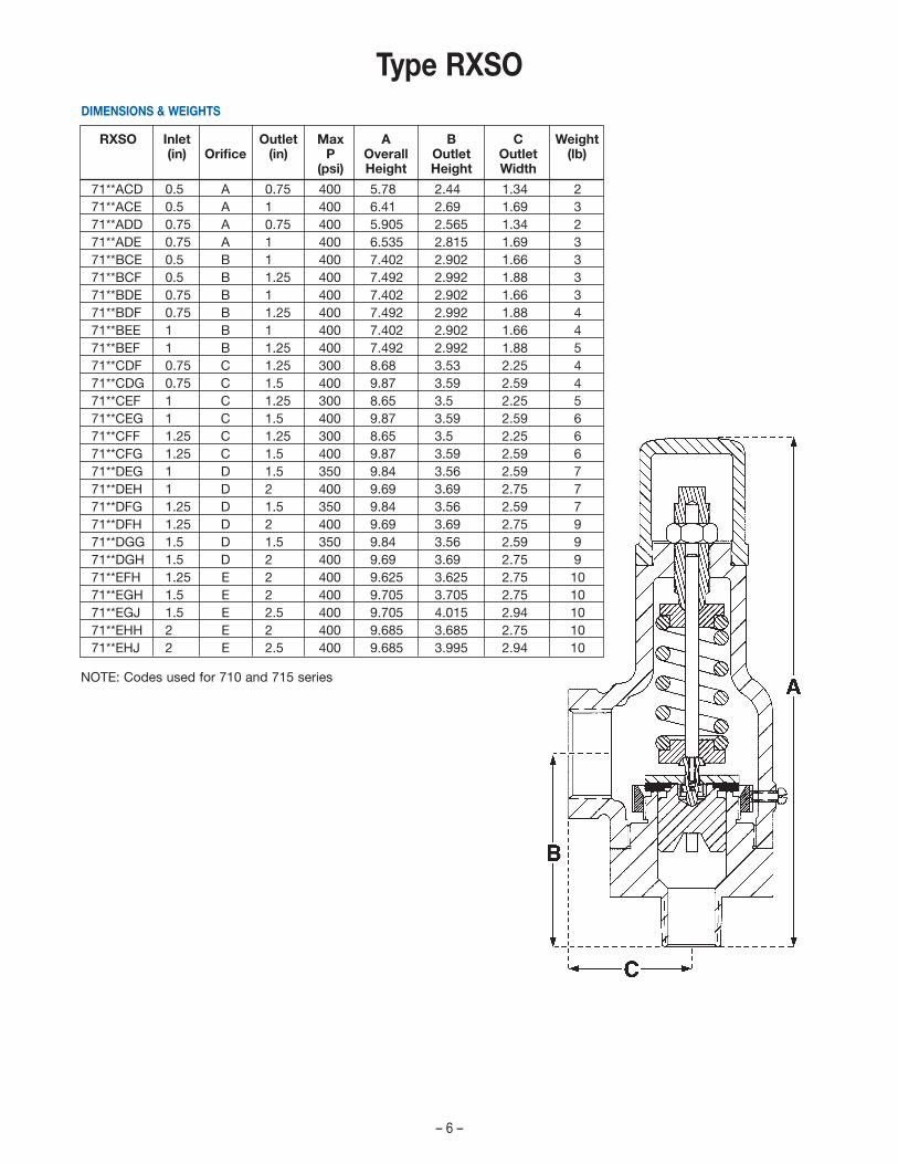
RXSO Inlet Outlet Max A B C Weight(in) Orifice (in) P Overall Outlet Outlet (lb)
(psi) Height Height Width
71**ACD 0.5 A 0.75 400 5.78 2.44 1.34 271**ACE 0.5 A 1 400 6.41 2.69 1.69 371**ADD 0.75 A 0.75 400 5.905 2.565 1.34 271**ADE 0.75 A 1 400 6.535 2.815 1.69 371**BCE 0.5 B 1 400 7.402 2.902 1.66 371**BCF 0.5 B 1.25 400 7.492 2.992 1.88 371**BDE 0.75 B 1 400 7.402 2.902 1.66 371**BDF 0.75 B 1.25 400 7.492 2.992 1.88 471**BEE 1 B 1 400 7.402 2.902 1.66 471**BEF 1 B 1.25 400 7.492 2.992 1.88 571**CDF 0.75 C 1.25 300 8.68 3.53 2.25 471**CDG 0.75 C 1.5 400 9.87 3.59 2.59 471**CEF 1 C 1.25 300 8.65 3.5 2.25 571**CEG 1 C 1.5 400 9.87 3.59 2.59 671**CFF 1.25 C 1.25 300 8.65 3.5 2.25 671**CFG 1.25 C 1.5 400 9.87 3.59 2.59 671**DEG 1 D 1.5 350 9.84 3.56 2.59 771**DEH 1 D 2 400 9.69 3.69 2.75 771**DFG 1.25 D 1.5 350 9.84 3.56 2.59 771**DFH 1.25 D 2 400 9.69 3.69 2.75 971**DGG 1.5 D 1.5 350 9.84 3.56 2.59 971**DGH 1.5 D 2 400 9.69 3.69 2.75 971**EFH 1.25 E 2 400 9.625 3.625 2.75 1071**EGH 1.5 E 2 400 9.705 3.705 2.75 1071**EGJ 1.5 E 2.5 400 9.705 4.015 2.94 1071**EHH 2 E 2 400 9.685 3.685 2.75 1071**EHJ 2 E 2.5 400 9.685 3.995 2.94 10
DIMENSIONS & WEIGHTS
Type RXSO
NOTE: Codes used for 710 and 715 series
– 7 –
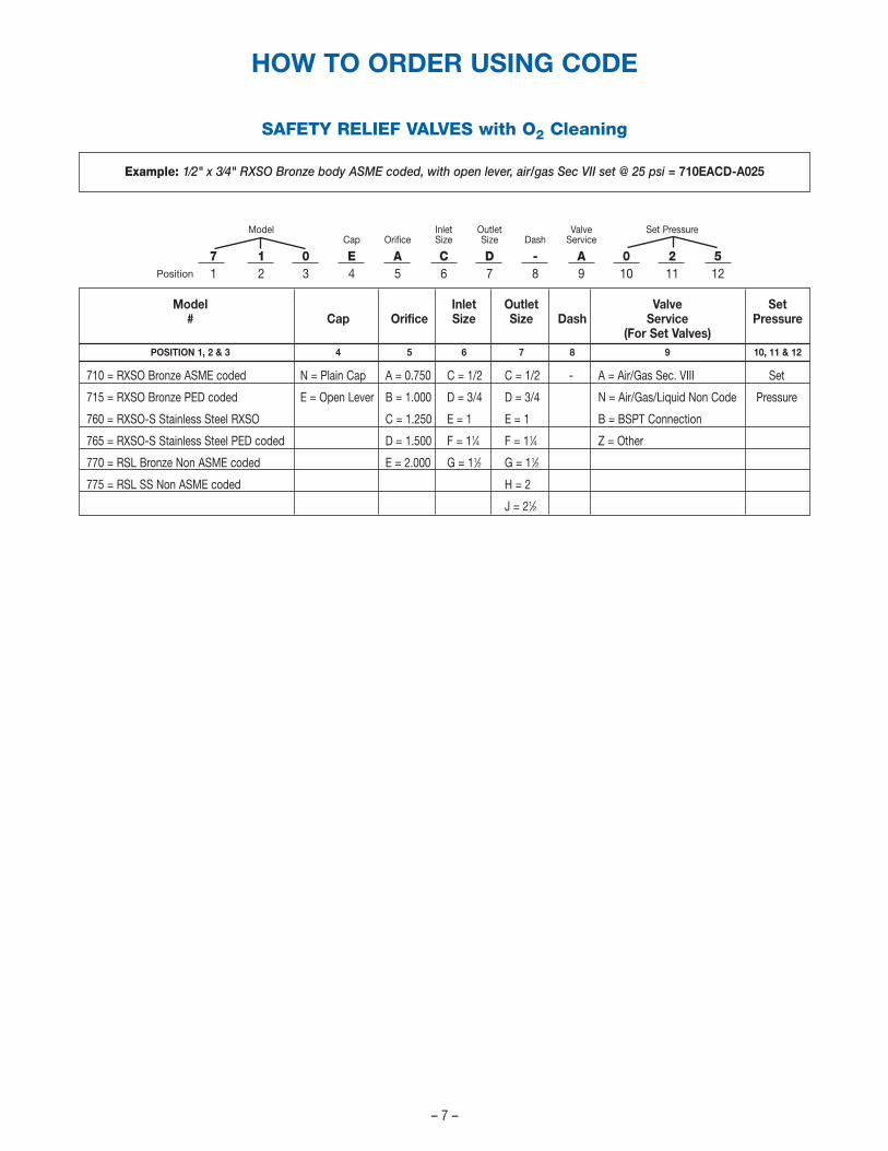
Model Inlet Outlet Valve Set PressureCap Orifice Size Size Dash Service
7 1 0 E A C D - A 0 2 51 2 3 4 5 6 7 8 9 10 11 12
SAFETY RELIEF VALVES with O2 Cleaning
Model Inlet Outlet Valve Set# Cap Orifice Size Size Dash Service Pressure
(For Set Valves)POSITION 1, 2 & 3 4 5 6 7 8 9 10, 11 & 12
710 = RXSO Bronze ASME coded N = Plain Cap A = 0.750 C = 1/2 C = 1/2 - A = Air/Gas Sec. VIII Set
715 = RXSO Bronze PED coded E = Open Lever B = 1.000 D = 3/4 D = 3/4 N = Air/Gas/Liquid Non Code Pressure
760 = RXSO-S Stainless Steel RXSO C = 1.250 E = 1 E = 1 B = BSPT Connection
765 = RXSO-S Stainless Steel PED coded D = 1.500 F = 11⁄4 F = 11⁄4 Z = Other
770 = RSL Bronze Non ASME coded E = 2.000 G = 11⁄2 G = 11⁄2
775 = RSL SS Non ASME coded H = 2
J = 21⁄2
HOW TO ORDER USING CODE
Example: 1⁄2" x 3⁄4" RXSO Bronze body ASME coded, with open lever, air/gas Sec VII set @ 25 psi = 710EACD-A025
Position
CRYOGENICS COMPANYA
– 8 –
®
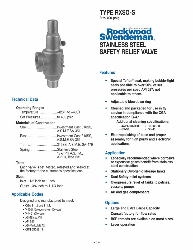
Technical Data
Operating RangesTemperature ……………-423˚F to +400˚FSet Pressures ……………to 400 psig
Materials of ConstructionShell ………………………Investment Cast 316SS,
A.S.M.E SA-351Base ………………………Investment Cast 316SS,
A.S.M.E SA-351Trim ………………………316SS, A.S.M.E. SA-479Spring ……………………Stainless Steel
17-7 PH A.S.T.M.,A-313, Type 631
TestsEach valve is set, tested, retested and sealed atthe factory to the customer’s specifications.
SizesInlet - 1/2 inch to 1 inchOutlet - 3/4 inch to 1-1/4 inch
Applicable CodesDesigned and manufactured to meet:
• CGA S-1.2 and S-1.3.• V-4301 (Cryogenic Non-Oxygen)• V-4401 (Oxygen)• ASME sec.VIII• API 527• AD-Merkblatt A2• CRN 0G0591.9
STAINLESS STEELSAFETY RELIEF VALVE
Features
• Special Teflon® seat, making bubble-tightseals possible to over 90% of setpressures per spec API 527; notapplicable to steam.
• Adjustable blowdown ring
• Cleaned and packaged for use in O2
service in compliance with the CGA specification G-4.1
Additional cleaning specifications: • 4WPI-SW70003 • ES.660.503• GS-38 • GS-40
• Electropolishing of base and properassembly for high purity and electronicapplications
Application• Especially recommended where corrosive
or expensive gases benefit from stainlesssteel construction.
• Stationary Cryogenic storage tanks• Dual Safety relief systems• Overpressure relief of tanks, pipelines,
vessels, pumps• Air and gas compressors
Options• Large and Extra Large Capacity
Consult factory for flow rates• BSP threads are available on most sizes.• Lever operation
TYPE RXSO-S0 to 400 psig

Type RXSO-SDimensions & Characteristics
AIR CAPACITY TABLEDischarge capacities in cubic feet per minute of air at 10% or 3 PSI, whichever is greater, overpressure.
– 9 –
Inlet Sizes 1/2
Inches 1/2 3/43/4 1
Outlet Sizes 3/4Inches 1 1-1/4Seat Diameter A BInches 0.750 1.000
Flow Area 0.118 0.204
Set Pressure10 36 6315 43 7420 48 8525 55 9630 62 10835 70 12040 77 13345 84 14550 91 15755 98 17060 105 18265 113 19570 120 20775 127 22080 134 23285 141 24490 149 25795 156 269100 163 282105 170 294110 177 307115 184 319120 192 331125 199 344130 206 356135 213 369
Inlet Sizes 1/2
Inches 1/2 3/43/4 1
Outlet Sizes 3/4Inches 1 1-1/4Seat Diameter A BInches 0.750 1.000
Flow Area 0.118 0.204
Set Pressure140 220 381145 228 393150 235 406155 242 418160 249 431165 256 443170 264 456175 271 468180 278 480185 285 493190 292 505195 299 518200 307 530205 314 543210 321 555215 328 567220 335 580225 343 592230 350 605235 357 617240 364 629245 371 642250 378 654255 386 667260 393 679265 400 692
Inlet Sizes 1/2
Inches 1/2 3/43/4 1
Outlet Sizes 3/4Inches 1 1-1/4Seat Diameter A BInches 0.750 1.000
Flow Area 0.118 0.204
Set Pressure270 407 704275 414 716280 422 729285 429 741290 436 754295 443 766300 450 779305 458 791310 465 803315 472 816320 479 828325 486 841330 493 853335 501 866340 508 878345 515 890350 522 903355 529 915360 537 928365 544 940370 551 952375 558 965380 565 977385 990 989390 580 1002395 587 1015400 594 1027
TO ORDER: See Page 7
Note: Pressure Settings below 15psig (1.034 barg) are non code.
RXSO-S Inlet Outlet Max A B C Weight(in) Orifice (in) P Overall Outlet Outlet (lb)
(psi) Height Height Width
76**ACD 0.5 A 0.75 400 5.78 2.44 1.34 276**ACE 0.5 A 1 400 6.41 2.69 1.69 376**ADD 0.75 A 0.75 400 5.905 2.565 1.34 276**ADE 0.75 A 1 400 6.535 2.815 1.69 376**BCF 0.5 B 1.25 400 7.492 2.992 1.88 376**BDF 0.75 B 1.25 400 7.492 2.992 1.88 476**BEF 1 B 1.25 400 7.492 2.992 1.88 5
DIMENSIONS & WEIGHTS
NOTE: Codes used for 760 and 765 series

CRYOGENICS COMPANYA
– 10 –
®
Features
• Teflon® seat for improved seat tightness• Cleaned and packaged for use in O2
service in compliance with the CGA specification G-4.1
Additional cleaning specifications: • 4WPI-SW 7003• GS-38
Applications
• Tanks, pumps, pipe lines and othervessels containing non-corrosive liquid,and where large relieving capacities arenot required.
Options
• BSP threads available on most sizes• Lever operation
Technical Data
Operating RangesTemperature ……………………………0 to +300˚FSet Pressures …………………………to 300 psig
For use with back pressure services, please consult factory.
Materials of Construction
BRONZEShell . . . . .Cast Bronze, A.S.M.E. SB-62Base . . . . .Forged Brass, Alloy C37700Trim . . . . . .Copper AlloySpring . . . .Stainless Steel
17-7 PH A.S.T.M., A-313, Type 631STAINLESS STEEL
Shell . . . . .Investment Cast 316SS, A.S.M.E SA-351Base . . . . .Investment Cast 316SS, A.S.M.E SA-351Trim . . . . . .316SS, A.S.M.E. SA-479Spring . . . .Stainless Steel
17-7 PH, A.S.T.M., A-313, Type 631
TestsEach valve is set, tested and retested at thefactory to the customer’s specifications.
SizesBronze Inlet - 1/2 inch to 2 inches
Outlet - 3/4 inch to 2-1/2 inchStainless Steel Inlet - 1/2 inch to 1 inch
Outlet - 3/4 inch to 1-1/4 inch
BRONZE & STAINLESS STEEL SAFETY RELIEF VALVES
TYPE RSL0 - 300 psig

– 11 –
Type RSLWATER CAPACITY TABLERate of discharge in gallons of water per minute at set pressure plus 25% accumulation or overpressure.
Inlet Sizes1/2 3/4 1
Inches1/2 3/4 1 1-1/4 1-1/23/4 1 1-1/4 1-1/2 2
Outlet Sizes 3/4 1 1-1/4 1-1/2 21 1-1/4 1-1/2 2 2-1/2
Seat Diameter A B C D EInches .75 1.00 1.25 1.50 2.00Flow Area .118 0.204 0.326 0.424 0.628Set Pressure
5 10.5 17.6 28.1 36.5 54.110 12.0 20.0 32.0 41.6 61.615 13.3 22.2 35.5 46.1 68.320 14.5 24.2 38.6 50.3 74.425 15.6 26.0 41.6 54.1 80.130 16.6 27.7 44.3 57.6 85.335 17.6 29.3 46.9 61.0 90.340 18.5 30.9 49.3 64.1 95.045 19.4 32.3 51.6 67.2 99.550 20.2 33.7 53.9 70.1 103.855 21.0 35.1 56.0 72.9 107.960 21.8 36.3 58.1 75.5 111.965 22.5 37.6 60.1 78.1 115.770 23.3 38.8 62.0 80.6 119.475 24.0 40.0 63.9 83.1 123.080 24.6 41.1 65.7 85.4 126.585 25.3 42.2 67.4 87.7 129.990 25.9 43.3 69.2 89.9 133.295 26.6 44.3 70.8 92.1 136.5100 27.2 45.4 72.5 94.3 139.6105 27.8 46.4 74.1 96.3 142.7110 28.4 47.3 75.6 98.4 145.7115 29.0 48.3 77.2 100.4 148.7120 29.5 49.2 78.7 102.4 151.6125 30.1 50.2 80.2 104.3 154.4130 30.6 51.1 81.6 106.2 157.2135 31.2 52.0 83.1 108.0 160.0140 31.7 52.8 874.5 109.8 162.7145 32.2 53.7 85.8 111.6 165.4150 32.7 54.6 87.2 113.4 168.0155 33.2 55.4 88.5 115.1 170.5160 33.7 56.2 89.8 116.9 173.1165 34.2 57.0 91.1 118.5 175.6170 34.7 57.8 92.4 120.2 178.0175 35.1 58.6 93.7 121.9 180.5180 35.6 59.4 94.9 123.5 182.9185 36.1 60.2 96.2 125.1 185.3190 36.5 60.9 97.4 126.7 187.6195 37.0 61.7 98.6 128.2 189.9200 37.4 62.4 99.8 129.8 192.2205 37.9 63.2 100.9 131.3 194.4210 38.3 63.9 102.1 132.8 196.7215 38.7 64.6 103.2 134.3 196.9220 39.2 65.3 104.4 135.7 201.1225 39.6 66.0 105.5 137.2 203.2230 40.0 66.7 106.6 138.6 205.3235 40.4 67.4 107.7 140.1 207.5240 40.8 68.1 108.8 141.5 209.5245 41.2 68.7 109.9 142.9 211.6250 41.6 69.4 110.9 144.3 213.7255 42.0 70.1 112.0 145.6 215.7260 42.4 70.7 113.0 147.0 217.7265 42.8 71.4 114.1 148.3 219.7270 43.2 72.0 115.1 149.7 221.7275 43.5 72.6 116.1 151.0 223.6280 43.9 73.3 117.7 152.3 225.6285 44.3 73.9 118.1 153.6 227.5290 44.7 74.5 119.1 154.9 229.4295 45.0 75.1 120.1 156.2 231.3300 45.4 75.7 121.0 157.4 233.2
Dimensions & Characteristics
TO ORDER: See Page 7
RSL Inlet Outlet Max A B C Wgt.(in) Orifice (in) P Overall Outlet Outlet (lb)
(psi) Height Height Width
770*ACC 0.5 A 0.5 300770*ACD 0.5 A 0.75 300 5.78 2.44 1.34 2770*ACE 0.5 A 1 300 6.41 2.69 1.69 3770*ADD 0.75 A 0.75 300 5.905 2.565 1.34 2770*ADE 0.75 A 1 300 6.535 2.815 1.69 3770*BDE 0.75 B 1 300 7.402 2.902 1.66 3770*BEE 1 B 1 300 7.402 2.902 1.66 4770*CFF 1.25 C 1.25 300 8.65 3.5 2.25 6770*DGG 1.5 D 1.5 300 9.84 3.56 2.59 9770*DGH 1.5 D 2 300 9.69 3.69 2.75 9770*EGH 1.5 E 2 300 9.705 3.705 2.75 10770*EHH 2 E 2 300 9.685 3.685 2.75 10770*EHJ 2 E 2.5 300 9.685 3.995 2.94 10
DIMENSIONS & WEIGHTS
RSL-S Inlet Outlet Max A B C Wgt.(in) Orifice (in) P Overall Outlet Outlet (lb)
(psi) Height Height Width
775*ACD 0.5 A 0.75 300 5.78 2.44 1.34 2775*ADD 0.75 A 0.75 300 5.905 2.565 1.34 2775*BEF 1 B 1.25 300 7.492 2.992 1.88 5
DIMENSIONS & WEIGHTS
CRYOGENICS COMPANYA
– 12 –
®
CRYOGENICS COMPANYA
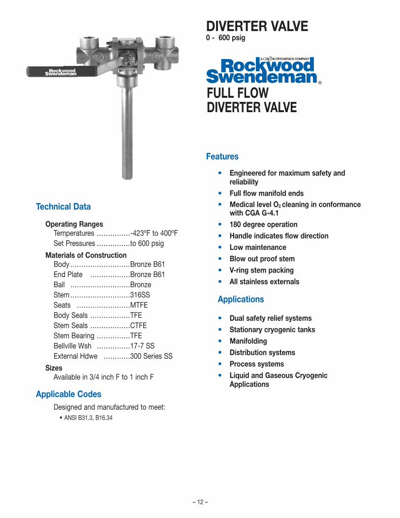
Features
• Engineered for maximum safety andreliability
• Full flow manifold ends• Medical level O2 cleaning in conformance
with CGA G-4.1• 180 degree operation• Handle indicates flow direction• Low maintenance• Blow out proof stem• V-ring stem packing• All stainless externals
Applications
• Dual safety relief systems• Stationary cryogenic tanks• Manifolding• Distribution systems• Process systems• Liquid and Gaseous Cryogenic
Applications
FULL FLOW DIVERTER VALVE
Technical Data
Operating RangesTemperatures ……………-423ºF to 400ºFSet Pressures ……………to 600 psig
Materials of ConstructionBody………………………Bronze B61End Plate ………………Bronze B61Ball ………………………BronzeStem………………………316SSSeats ……………………MTFEBody Seals ………………TFEStem Seals ………………CTFEStem Bearing ……………TFEBellville Wsh ……………17-7 SSExternal Hdwe …………300 Series SS
SizesAvailable in 3/4 inch F to 1 inch F
Applicable CodesDesigned and manufactured to meet:
• ANSI B31.3, B16.34
DIVERTER VALVE0 - 600 psig

DIVERTER VALVE
Safety Relief Valve Outlet Rupture Disc Outlet Torque
CV@ CV@ CV@ CV@Sizes mid position full open mid position full open Max.(inches) (90°) (180°) (90°) (180°) Value
3⁄4F 9.2 8.2 10.7 8.1 200 in. lbs.
1F 25.3 18.3 16.4 14.0 300 in. lbs.
HIGH FLOW DIVERTER VALVE CV VALUES*
10.0
10.0 20.0 30.0 40.0 50.0 60.0 70.0 80.0 90.0 100.0
20.0
30.0
40.0
50.0
45.0
35.0
25.0
15.0
5.0
0.0
P E R C E N T O P E N
C V
* Flows may vary slightly due to outlet connection sizes.
Dimensions & Characteristics
– 13 –
3⁄4F1F
B
D
C
A
Size A B C D3⁄4F 13.00 9.38 7.25 7.751F 17.66 11.61 8.73 12.00
Dimensions for reference only
DIMENSIONS (inches)
HIGH FLOW DIVERTER VALVE Cv GRAPH
TO ORDER: See Page 16
CRYOGENICS COMPANYA
®
CRYOGENICS COMPANYA
– 14 –
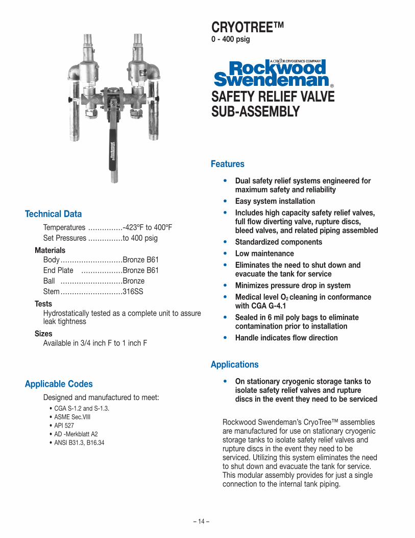
Features
• Dual safety relief systems engineered formaximum safety and reliability
• Easy system installation• Includes high capacity safety relief valves,
full flow diverting valve, rupture discs,bleed valves, and related piping assembled
• Standardized components• Low maintenance• Eliminates the need to shut down and
evacuate the tank for service• Minimizes pressure drop in system• Medical level O2 cleaning in conformance
with CGA G-4.1• Sealed in 6 mil poly bags to eliminate
contamination prior to installation• Handle indicates flow direction
Applications
• On stationary cryogenic storage tanks toisolate safety relief valves and rupturediscs in the event they need to be serviced
Rockwood Swendeman’s CryoTree™ assembliesare manufactured for use on stationary cryogenicstorage tanks to isolate safety relief valves andrupture discs in the event they need to beserviced. Utilizing this system eliminates the needto shut down and evacuate the tank for service.This modular assembly provides for just a singleconnection to the internal tank piping.
Technical DataTemperatures ……………-423ºF to 400ºFSet Pressures ……………to 400 psig
MaterialsBody………………………Bronze B61End Plate ………………Bronze B61Ball ………………………BronzeStem………………………316SS
TestsHydrostatically tested as a complete unit to assureleak tightness
SizesAvailable in 3/4 inch F to 1 inch F
Applicable CodesDesigned and manufactured to meet:
• CGA S-1.2 and S-1.3.• ASME Sec.VIII• API 527• AD -Merkblatt A2• ANSI B31.3, B16.34
SAFETY RELIEF VALVESUB-ASSEMBLY
CRYOTREE™0 - 400 psig

– 15 –
CRYOTREE™Dimensions & Characteristics
SIZE A B C
3⁄4F 5.9 22.5 14.8
1F 8.7 25.7 16.5
Safety Relief Valve Outlet Rupture Disc Outlet
CV@ CV@ CV@ CV@Size mid position full open mid position full open
(inches) (90°) (180°) (90°) (180°)
3⁄4F 9.2 8.2 10.7 8.1
1F 25.3 18.3 16.4 14.0
Flows may vary slightly due to outlet connection sizes.
DIMENSIONS - INCHES
HIGH FLOW DIVERTER VALVE CV VALUES*
10.0
10.0 20.0 30.0 40.0 50.0 60.0 70.0 80.0 90.0 100.0
20.0
30.0
40.0
50.0
45.0
35.0
25.0
15.0
5.0
0.0
P E R C E N T O P E N
C V
3⁄4F1F
Dimensions for reference only.
HIGH FLOW DIVERTER VALVE Cv GRAPH
TO ORDER: See Page 16

– 16 –
SC RS/0707
CRYOTREE™
SRV1 Rupture Purge Rupture3, 4
Model Inlet Size Options Inlet Disc Valve Disc Dash SRV Outlet & Orifice SRVSize Size Location Setting Setting
POSITIONS1, 2 & 3 4 5 6 7 8 9 10 11 & 12 13, 14 & 15
790 D = 3/4" F = Standard D = 3/4" A = 1/4" A2
= Side 3 = 130% - DA = 3/4" Outlet, A Orif nnn
E = 1" T = Tag for Customer E = 1” B = 3/8" B = Bottom 4 = 140% EA = 1" Outlet, A Orif
F = 11⁄4" C = 1/2" B = 150% EB = 1"Outlet, B Orif
D = 3/4" 6 = 160% FB = 11⁄4" Outlet, B Orif
E = 1" 7 = 170% FC = 11⁄4" Outlet, C Orif
8 = 180% GC = 11⁄2" Outlet, C Orif
9 = 190% GD = 11⁄2" Outlet, D Orif
0 = 200% HD = 2" Outlet, D Orif
HE = 2" Outlet, E Orif
Diverter Max NPTSize Top Side Bottom3/4" 3/4" 3/4" 1/2"1" 11⁄4" 1" 1"
1. Diverter Top Port
2. A is the standardCryotree only available with 1/4" side or bottom port
3. Rupture Disc setting over SRV set pressure(example: 150psi X 150% = 225psi)Actual settings to be in 5 psi increments (prefered)
4. B is the standard
SRV Rupture Purge Rupture SRV Outlet SRVModel Inlet Disc Valve Disc & Orifice Settings
Size Options Size Size Location Setting Dash
7 9 0 D F D C A B - F B 1 5 01 2 3 4 5 6 7 8 9 10 11 12 13 14 15
HOW TO ORDER USING CODE
Example: 3/4" Full with 3/4" B 1-1/4" SRV @ 150psi & 1/2" Rupture Disc @ 225psi = 790DFDCAB-FB150
Position
Model Inlet Size Orifice Top Port Bottom Port Side Port MaterialPOSITION 1, 2 & 3 4 5 6 7 8 9
780 D = 3/4" F = Full D = 3/4" A = 1/4" A = 1/4" B = BronzeE = 1" T = Tag for Customer E = 1" B = 3/8" B = 3/8"
F = 11⁄4" C = 1/2" C = 1/2"D = 3/4" D = 3/4"E = 1" E = 1"
DIVERTER
Model Inlet Top Bottom SideSize Orifice Port Port Port Material
7 8 0 D F D C A B1 2 3 4 5 6 7 8 9
Example: 3/4" Full with 3/4" Top, 1/2" Bottom and 1/4" Side Ports = 780DFDCAB
Position
Diverter Max NPTSize Top Side Bottom3/4" 3/4" 3/4" 1/2"1" 11⁄4" 1" 1"

N O T E S
CRYOGENICS COMPANYA

150 COLDENHAM ROAD, WALDEN, NEW YORK 12586-2035800.210.1300 • 845.778.5566 • Fax 845.778.1072