a critical analysis of the forth rail bridge, … · figure 1: the forth rail bridge figure 2:...
TRANSCRIPT

Figure 1: The forth rail bridge
Figure 2: Location of forth rail bridge
A CRITICAL ANALYSIS OF THE FORTH RAIL BRIDGE, 1890
SCOTLAND
Divya Gupta1
1MEng Undergraduate Student - University of Bath
Abstract: The following paper analyses the design and the construction of the Forth Rail Bridge in Scotland.
The Forth Rail Bridge is one of the most iconic bridges in engineering history and great interest to engineers.
Other considerations in this paper include the aesthetic quality of the bridge, the maintenance of the bridge
today and the future improvements to the bridge.
Keywords: Forth rail, cantilever, steel, suspended span, Scotland
1 Introduction
The Forth Rail Bridge is considered to be one
of the most recognisable bridges in the world and
greatest engineering feats of its time. It was the first
bridge in Britain to be built entirely out of steel and
also the longest single-span bridge at the time of
completion. The bridge was built out of the necessity to
enable trains access to Northern Scotland across the
Firth. Various engineering challenges were associated
with the crossing of the Firth and several proposals
were presented such as tunnels, roads and railways and
also methods to improve the ferry landings at the time.
In 1873, Sir Thomas Bouch designed a double span
steel suspension bridge. The bridge construction had
already begun in 1879 when the Tay Bridge fell and
the proposal was then abandoned. In 1881, Sir John
Fowler and Benjamin Baker brought forward the
proposal for a cantilever bridge. After the disaster of
the Tay Bridge, the Board of Trade felt it was
necessary to have a design that induced a feeling of
safety and confidence in the public using it. Cantilever
bridges had never been built in Britain before and
although they had been built in the Far East, the spans
Proceedings of Bridge Engineering 2 Conference 2011
April 2011, University of Bath, Bath, UK
1 Divya Gupta ([email protected])
involved were much smaller than the lengths proposed
for the Forth. Thus this design was met with much
speculation. Steel was a fairly ‘new’ material in Britain
and its use was limited due to engineers’ hesitations
about its brittleness in comparison to wrought iron.
However, steel was an attractive material for use in
long spans due to its ability to carry 50% increased
working stresses. After much careful consideration,
work begun on the Forth in 1883 and it was completed
in 1890. [1]
Before the bridge was built, this area of
Scotland was suffering from economic stagnation due
to the inefficient transport between the two shores of
the Firth. Today the bridge allows the crossing of trains
directly from the South into the North of Scotland
connecting the two shores and promoting economic
growth. [4]
Even 120 years after its completion the
bridge stands tall as a proud monument to civil
engineering and serves as a thoroughfare for nearly 200
trains a day.
2 Aesthetics
The aesthetics of a bridge is a very subjective
matter that varies from person to person. It is difficult
to determine what makes a bridge beautiful. Despite
this subjectivity, Fritz Leonhardt developed the 10
rules of aesthetics which are essential to the design of a
bridge: fulfilment of function, proportions, order within
the structure, refinement of design, integration into the
environment, surface texture, colour of components,
character, complexity in variety and incorporation of
nature. It is not necessary for a bridge to fulfil all of
these requirements to be an aesthetically pleasing
bridge. [3]
The Forth Rail Bridge clearly fulfils its
function of providing a link which trains may use to
cross the Firth. The structure of the bridge is obvious in
that the main cantilever towers support the suspended
span in the middle.
The bridge is well proportioned due to the
whole span of the bridge being equally divided by the
towers and cantilevers. The bridge is completely
symmetrical which adds to its visual attraction. Even
though the depth of the bridge is quite small compared
to the overall length it does not seem disproportionate
and rather looks more stable. The elements of the truss
frame that provide the lateral and vertical stability to
the towers are in proportion to one another and the
bracing behind the main elements does not detract from
the visual appeal of the main frame.
Order is hard to accomplish in truss bridges
due to the presence of many elements. However in this
case the structural members and the bracing of the
towers were designed while taking order into
consideration. The elements of equal length running in
one direction are ordered well and when looking at the
bridge straight on a clear ordered structure can be seen.
The bracing and smaller elements are not seen and
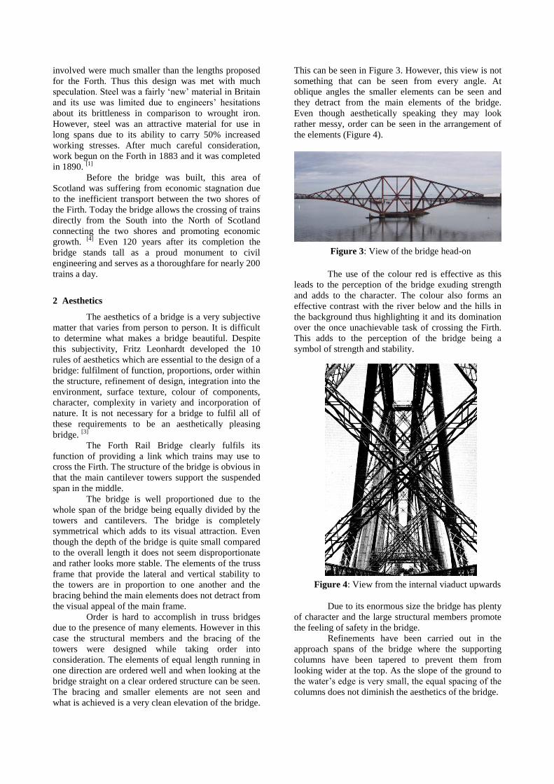
what is achieved is a very clean elevation of the bridge.
This can be seen in Figure 3. However, this view is not
something that can be seen from every angle. At
oblique angles the smaller elements can be seen and
they detract from the main elements of the bridge.
Even though aesthetically speaking they may look
rather messy, order can be seen in the arrangement of
the elements (Figure 4).
The use of the colour red is effective as this
leads to the perception of the bridge exuding strength
and adds to the character. The colour also forms an
effective contrast with the river below and the hills in
the background thus highlighting it and its domination
over the once unachievable task of crossing the Firth.
This adds to the perception of the bridge being a
symbol of strength and stability.
Due to its enormous size the bridge has plenty
of character and the large structural members promote
the feeling of safety in the bridge.
Refinements have been carried out in the
approach spans of the bridge where the supporting
columns have been tapered to prevent them from
looking wider at the top. As the slope of the ground to
the water’s edge is very small, the equal spacing of the
columns does not diminish the aesthetics of the bridge.
Figure 3: View of the bridge head-on
Figure 4: View from the internal viaduct upwards

The vertical columns of the tower are straight
when viewed from the side but when seen from the
front slope inwards at a rate of 1:7.5. This is due to the
use of the effect of the Holbein straddle. A German
artist Hans Holbein painted men’s feet with a straddle
giving the impression of great stability. This same
concept was used in the design of the towers giving the
structure harmonious and simple lines and creates a
perception of great stability and resistance to wind
pressure.
The Forth Rail Bridge is a beautiful landmark
that depicts the advance in the engineering industry in
the 19th
century.
3 Key Aspects of the Bridge
3.1 Location and Geology
The location on which the bridge stands today
was determined by the amount of headroom required
by ships navigating the Firth and also by judgement of
the levels of the ground on both shores. The Firth only
contracts at this location in its whole length, the width
being just over 1600m at this point and at least 3200m
elsewhere.
The rocky headland projecting south from the
Fife shore was a good source for building material and
a perfect shelter for unloading vessels which is ideal
during construction. South of the headland, at a
distance of about 540m the Inchgarvie Island exists.
This island is formed from whinstone rock which
extends halfway through the south channel of the Firth
and then disappears. A deep layer of hard boulder clay
continues to cover the south channel and rises at the
edge towards the shore at a gentle slope. Freestone
ledges are formed as the clay disappears half way up
the slope. Therefore, the rock provides perfect ground
conditions for the foundations of the three cantilever
towers.
The north and south towers are approximately
equidistant from the central tower so that there are two
equally long spans. The depth of both channels exceeds
60m. There were no problems encountered for the
ground conditions for foundations of the approach
spans. Overall, it was incredible that the geological
conditions of the site were not troublesome. Given
these considerations it made perfect to choose this
location for the bridge. [4]
3.2 Material
During the period in which the Forth was
being designed steel was a relatively rare material to be
used for the construction of a bridge. Steel was more
brittle compared to wrought iron which caused
engineers to have reservations about its use. Given that
steel was a considered a new material, knowing its
chemical composition was insufficient and physical
testing on the material would be needed to deduce its
mechanical properties. Steel was an attractive material
for the use in long span bridges due to its ability to
withstand 50% increased working stresses compared to
wrought iron. This increased strength is due to the
presence of carbon in the steel which makes it harder
than wrought iron. Baker and Fowler approached the
Board of Trade to propose the allowable working stress
in the steel to be 25% of the ultimate stress. The Board
accepted this and did not apply any further regulations
on the differentiation between tension and compression
members, the effects of live load or dead load
independently or applied together. Thus Baker and
Fowler had to develop the design rules for working
stresses using careful experiments and thought. [1]
3.3 Foundations
Each tower comprises four vertical columns
each of which is supported by a circular granite
masonry pier. Each pier is constructed to a height of
5.5m above the high water level. The foundations were
placed at points on the riverbed where there was either
hard whinstone rock or hard boulder clay. These
geological conditions were suitable for the
withstanding of heavy loads without settlement. Also,
this prevented the need for high air pressure to be used
to keep the water out of the caissons during
construction. [4]
Figure 5: Forth rail bridge at night
Figure 6: Caisson at south main pier

3.4 Cantilever Towers
There are three double cantilever towers in the
structure which support two central connecting girders
between them. A cantilever is projected from each side
of the cantilever tower which is supported by four
circular masonry piers. The north and south tower have
additional support as their ends rest on the cantilever
end piers. Since the central tower does not have this
additional support the base of the tower is made nearly
twice the width of the others. [4]
Almost identical, the only difference between
the North and South towers is that their outer
cantilevers are reversed. The six cantilevers are all
completely identical in length, height and width except
for the arrangement of the end-posts and the two outer
fixed cantilevers which are heavier in construction.
Each cantilever consists of a tension member at the top
and a compression member at the bottom. Six pairs of
cross-bracing on either side brace these members
together. One end of the cantilever is closed by the
vertical column and the other by the end-post. [4]
Each pair of cross-bracing consists of a strut
and a tie i.e. a compression and tension member
respectively. Their intersections are stiffened by strong
gusset plates and other stiffening methods. From these
intersections vertical ties which are lattice girders are
attached to the bottom members. This is done to relieve
the bottom compression members of deflection
between the junctions. Twelve sets of horizontal
diagonal cross-bracing connect the bottom members
together. The internal viaduct is supported by trestles
and cross-girders which also connect the bottom
members. [4]
The bottom horizontal members, the vertical
columns and the struts in the cantilevers had to be of a
tubular section as weight for weight this section gave
the maximum strength obtainable. This is due to the
absence of sharp edges where fatigue and hence failure
may occur due to local stress concentrations. Curved
surfaces are less prone to buckling. The tension
members at the top and the inclined tie members in the
cantilevers throughout the bridge are open lattice
girders. [4]
The bottom member of the cantilevers is not
one continuous tube but of a polygonal form made of
six straight tubes bolted together. This is not only
because a straight tube has higher strength but also
because by having this design the construction of the
bottom member is simplified. The top member is one
continuous lattice girder that decreases in cross-section
in the direction of the end-post of the cantilever. [4]
In each of the towers horizontal bracing from
the intersection of the struts is attached to the vertical
columns. As the distance between the piers of the
central tower is too great, deflection of the horizontal
members is prevented by introduction of a vertical tie
from the intersection to the bottom member and a
vertical column from the intersection to the top
member. [1]
The members and bracing of the tower give it
immense strength and resistance to stresses induced by
all types of load combinations. All these stresses must
however be taken into the foundations via the
Figure 7: Inchgarvie tower
Free
Fixed
Figure 9: Arrangement of skewbacks
Figure 8: Detail of a skewback

Figure 10: Suspended span
connection between the tower and the foundation. Five
tubular sections and five lattice girder sections join at
this junction and terminate in a flat plate. This flat plate
is called the upper bedplate. A lower bedplate is
attached to the masonry pier on which the upper
bedplate rests or can move or slide upon. The junction
is called a skewback. Three of the four skewbacks are
free to accommodate for movement due to temperature
changes and the lateral pressure of the wind (Figure 9). [1]
3.5 Suspended Spans
The top member of the suspended span is
polygonal in form similar to the bottom member of the
cantilever. The bottom member is straight. There are
eight sets of cross-bracing between these members
comprising struts and ties. Similar to the cantilevers,
the struts are provided with diagonal wind bracing. A
vertical tie is provided from the intersection of the
struts and ties to the bottom member. This tie supports
the middle of the bottom member. The two top
members are connected with sixteen sets of diagonal
wind bracing. Solid plate girders run between the two
bottom members to provide bracing. They carry the rail
troughs. T-bracing and the solid floor of buckle plates
further increase the stiffness of the girders. The top
member and the struts of the suspended span are the
exception to rule of having tubular sections for
compression members. [4]
The suspended span acts as a simply
supported truss with the top member in compression
and the bottom in tension while under loading. The
bracing consisting of struts and ties in compression and
tension respectively provide the truss system.
3.6 Approach Viaducts
Although the approach viaducts are not one of
the main features of the Forth Rail Bridge they are still
substantial structures in themselves. The spans carry
the two track railway line through to the cantilever
towers at a uniform level and the same height above
the water. The approach span from the South consists
of four granite masonry arches that terminate at the
abutment for the south approach span. From here ten
girder spans begin in comparison to the five girder
spans in the North approach viaduct. [2]
The last span of each side is supported by the
respective cantilever end pier. The North approach
viaduct has three similar granite masonry arches.
3.7 Dimensions of the Bridge
The total length of the cantilever bridge is
1624.6m. This consists of the cantilever towers, the
central tower being 79.3m wide and the north and
south being 44.2m. The length of each of the six
cantilever arms is 207.3m and each suspended span is
106.7m long. The length of the North approach span is
295.1m to the end of the masonry arches and the South
approach span is 602.9m. [2]
The height of the twin railway tracks above
the high tide was 47.9m with a clearance of 46m above
the water under no train loading. The masonry piers
underneath the towers were built to clear the high
water levels by about 5.5m and the difference between
the top and bottom members of the tower is 100.5m.
Therefore, the overall height of the cantilever towers is
110m. [2]
4 Construction of the Bridge
The contract for the construction of the bridge
was awarded to Tancred, Arrol and Company on
December 21, 1882. The construction work was
divided into the following four classifications: site
preparation, construction of the foundations and
masonry piers, prefabrication of the steel and
construction of the main and approach spans. These
classifications weren’t necessarily focused on one after
Figure 11: Approach span

the other but also simultaneously. [1]
4.1 Foundations and Masonry Piers
To facilitate early construction of the masonry
piers, their accurate positions were determined at once.
Primarily, support piers were constructed. The
construction of the piers of the southern approach span
was accomplished with no complications. The
construction was done in conditions of full tide or half
tide using caissons. On the other hand, construction of
the piers of the northern approach spans was more
complicated due to the sloping rock below. Diamond
drilling and blasting was used to level this rock to
facilitate construction. [1]
There are four foundations per cantilever
tower, each of which was constructed within an iron
caisson of a diameter of 21.3m. Since the Queensferry
tower was based on boulder clay, its four foundations
were sunk under compressed air. The construction of
the foundations of the Fife tower was carried out in
open caissons due to the piers being founded on rock.
Due to the variable geology under the central
Inchgarvie pier, the two northern piers that were
founded on rock were sunk under open air conditions
while compressed air conditions were used to sink the
two southern piers. [1]
4.2 Fabrication of the steel
Prefabrication of the steel elements of the
bridge was done in specially built workshops and level
yard areas next to the construction site at South
Queensferry. Care was taken to ensure that the steel
was cold-worked to increases its yield stress. The main
columns that formed the main compressive members of
the bridge had to be constructed with curved plates due
to the limitation in the plate size available. The plates
were joined together with stiffened longitudinal joints
that were drilled and riveted. Similar drilling machines
were used for the box lattice construction of the tension
members and ties. [1]
4.3 Erection of the Bridge
The approach spans were first to be erected
with the steel erected over low level piers. Using
jacking operations, these were then raised to the
appropriate level and the required masonry put into
place (Figure 12). [1]
For the main cantilever towers, the first step
of construction was the placing of the lower flat plates
and then construction of the skewbacks. Platforms
supported completely by the skewbacks were
constructed 9-12m above the level of the deck. These
platforms carried the steam derrick cranes used for the
placement of the steel. Parts of the diagonal struts,
vertical members and cantilever struts were used for
the construction of these platforms to the greatest
height possible. Constant care was taken in ensuring
the correct positioning of the elements of the structure
using theodolites. Due to the inclination of the
members setting out was a difficult task. Once the
construction had reached a height of approximately
15m above the deck, lifting platforms were built. These
lifting platforms would facilitate the continuation of
the construction of the towers to their full height. A
system of movable support girders was used so that the
construction platform could be raised up with the
continuing construction of the tower. When the
working platforms reached a significant height riveting
cages were constructed on the undersides of the lifting
platforms. By working in these cages the labourers
were prevented from falling from height and their tools
were also safe from dropping and injuring others
below. The cages would rise with the lifting platform.
Depending on the maximum height the crane on the
platform could reach, the vertical columns were
constructed above the platform. In 1887, the
construction of the towers was completed. Removing
the erection platforms was a tedious task that needed to
be performed with the utmost caution as workers were
present on the lower portion of the structure. Any
falling piece of metal, however small, could prove
fatal. [1]
Constructing the cantilever sections was the
next step in the erection process. [1]
This was initiated
Figure 12: Raising approach spans to required height
Figure 13: Schematic of main tower erection

briefly before the lifting platform for the tower erection
reached the intersection of the diagonal vertical
members. [2]
Construction on both sides of the towers
was done simultaneously to maintain a balance (Figure
14).
The construction of the bottom member was
initiated by placing a crane near a skewback. About
30m of the member was constructed and then a
rectangular cage carrying the riveting machine was
built at its end. A hydraulic crane used for lifting the
next plates into place was positioned above this cage.
This can be seen in Figure 15. As the construction of
the bottom member continued, it was supported by a
link tie. The top members of the cantilevers were also
constructed at the same time. [1]
As the cantilevers were
being constructed, the girders for the viaduct were also
assembled by overhanging into the cantilevers. [2]
At the end of each cantilever the end post was
constructed, closed on three sides and open on the side
facing the suspended spans. The bottom member was
erected to the full extent of the end post while the top
member only to the inner side. Before the suspended
spans were constructed the distance between the
cantilever arms was measured carefully. This
measurement was taken on occasions of different
temperature conditions. The length of the suspended
spans was then ascertained and thermal expansion of
the spans under full summer heat was accommodated
for. Expansion of 0.6m is allowed for by fixing the
ends of the suspended spans at the Queensferry and
Fife ends and using rocking posts, slide blocks and
expansion joints in the rails on the Inchgarvie ends.
The loading of the suspended spans is supported
entirely by the top members and bracings and is carried
into the top of the end posts. The bottom member of
the spans has no load bearing connection with the end
posts of the cantilever. The method of construction of
the suspended spans is similar to that for the
cantilevers i.e. using overhanging. The ends of the
spans were initially fixed to the cantilevers until they
joined up and then were released. [2]
The construction of the suspended spans was
done by building out from the cantilevers (Figure 16).
The suspended spans could have been pre-fabricated
and transported by barges to the correct location and
then lifted into place by cranes. However, this method
was not adopted as it would have required heavy
cranes to be placed on either ends of the cantilevers
and could prove inherently dangerous if any cables
snapped during the lifting of the suspended span.
Snapping of a cable on one side of the span would
cause the complete load of the span to be supported by
one cantilever arm. This could lead to failure in the
members of the cantilever which would have a
detrimental consequence.
Construction of the suspended spans was
completed in November 1889. The bridge was tested
under train loads in January 1890 and the bridge was
officially opened on the 4th
March 1890. [1]
5 Structural Analysis of the Bridge
5.1 The Human Cantilever
The following demonstration using three men
was carried out in one of Sir Baker’s lectures to present
the principle behind the cantilever bridge.
Figure 14: Balanced construction
Figure 15: Erection of bottom member of cantilever Figure 16: Outward construction of suspended spans
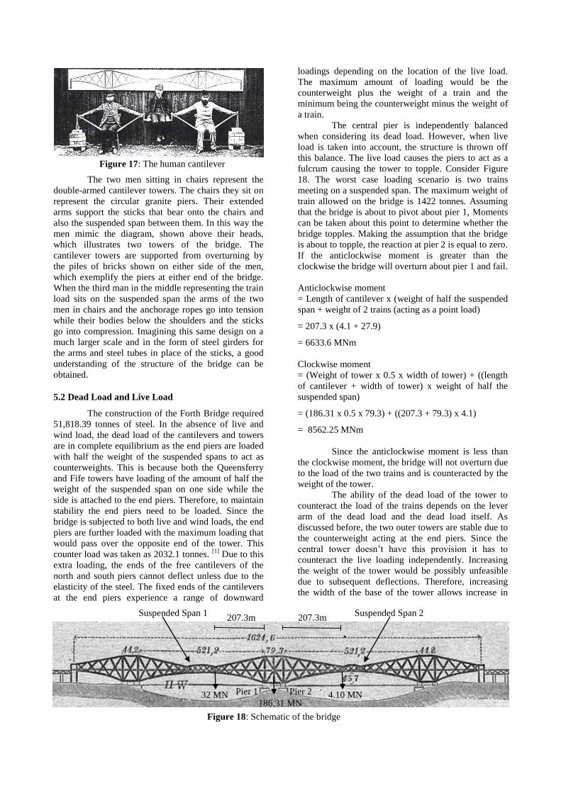
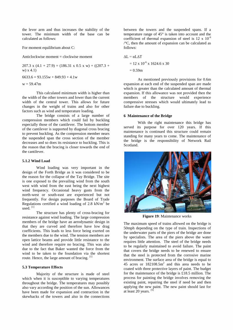
Figure 18: Schematic of the bridge
Pier 1 Pier 2
Suspended Span 1 Suspended Span 2
186.31 MN 4.10 MN 32 MN
207.3m 207.3m
The two men sitting in chairs represent the
double-armed cantilever towers. The chairs they sit on
represent the circular granite piers. Their extended
arms support the sticks that bear onto the chairs and
also the suspended span between them. In this way the
men mimic the diagram, shown above their heads,
which illustrates two towers of the bridge. The
cantilever towers are supported from overturning by
the piles of bricks shown on either side of the men,
which exemplify the piers at either end of the bridge.
When the third man in the middle representing the train
load sits on the suspended span the arms of the two
men in chairs and the anchorage ropes go into tension
while their bodies below the shoulders and the sticks
go into compression. Imagining this same design on a
much larger scale and in the form of steel girders for
the arms and steel tubes in place of the sticks, a good
understanding of the structure of the bridge can be
obtained.
5.2 Dead Load and Live Load
The construction of the Forth Bridge required
51,818.39 tonnes of steel. In the absence of live and
wind load, the dead load of the cantilevers and towers
are in complete equilibrium as the end piers are loaded
with half the weight of the suspended spans to act as
counterweights. This is because both the Queensferry
and Fife towers have loading of the amount of half the
weight of the suspended span on one side while the
side is attached to the end piers. Therefore, to maintain
stability the end piers need to be loaded. Since the
bridge is subjected to both live and wind loads, the end
piers are further loaded with the maximum loading that
would pass over the opposite end of the tower. This
counter load was taken as 2032.1 tonnes. [1]
Due to this
extra loading, the ends of the free cantilevers of the
north and south piers cannot deflect unless due to the
elasticity of the steel. The fixed ends of the cantilevers
at the end piers experience a range of downward
loadings depending on the location of the live load.
The maximum amount of loading would be the
counterweight plus the weight of a train and the
minimum being the counterweight minus the weight of
a train.
The central pier is independently balanced
when considering its dead load. However, when live
load is taken into account, the structure is thrown off
this balance. The live load causes the piers to act as a
fulcrum causing the tower to topple. Consider Figure
18. The worst case loading scenario is two trains
meeting on a suspended span. The maximum weight of
train allowed on the bridge is 1422 tonnes. Assuming
that the bridge is about to pivot about pier 1, Moments
can be taken about this point to determine whether the
bridge topples. Making the assumption that the bridge
is about to topple, the reaction at pier 2 is equal to zero.
If the anticlockwise moment is greater than the
clockwise the bridge will overturn about pier 1 and fail.
Anticlockwise moment
= Length of cantilever x (weight of half the suspended
span + weight of 2 trains (acting as a point load)
= 207.3 x (4.1 + 27.9)
= 6633.6 MNm
Clockwise moment
= (Weight of tower x 0.5 x width of tower) + ((length
of cantilever + width of tower) x weight of half the
suspended span)
= (186.31 x 0.5 x 79.3) + ((207.3 + 79.3) x 4.1)
= 8562.25 MNm
Since the anticlockwise moment is less than
the clockwise moment, the bridge will not overturn due
to the load of the two trains and is counteracted by the
weight of the tower.
The ability of the dead load of the tower to
counteract the load of the trains depends on the lever
arm of the dead load and the dead load itself. As
discussed before, the two outer towers are stable due to
the counterweight acting at the end piers. Since the
central tower doesn’t have this provision it has to
counteract the live loading independently. Increasing
the weight of the tower would be possibly unfeasible
due to subsequent deflections. Therefore, increasing
the width of the base of the tower allows increase in
Figure 17: The human cantilever
the lever arm and thus increases the stability of the
tower. The minimum width of the base can be
calculated as follows:
For moment equilibrium about C:
Anticlockwise moment = clockwise moment
207.3 x (4.1 + 27.9) = (186.31 x 0.5 x w) + ((207.3 +
w) x 4.1)
6633.6 = 93.155w + 849.93 + 4.1w
w = 59.47m
This calculated minimum width is higher than
the width of the other towers and lower than the current
width of the central tower. This allows for future
changes in the weight of trains and also for other
factors such as wind and temperature loading.
The bridge consists of a large number of
compression members which could fail by buckling
especially those of the cantilever. The bottom member
of the cantilever is supported by diagonal cross bracing
to prevent buckling. As the compression member nears
the suspended span the cross section of the member
decreases and so does its resistance to buckling. This is
the reason that the bracing is closer towards the end of
the cantilever.
5.1.2 Wind Load
Wind loading was very important in the
design of the Forth Bridge as it was considered to be
the reason for the collapse of the Tay Bridge. The site
is one exposed to the prevailing wind from the south
west with wind from the east being the next highest
wind frequency. Occasional heavy gusts from the
north-west or south-east are experienced but not
frequently. For design purposes the Board of Trade
Regulations certified a wind loading of 2.8 kN/m2 be
used. [1]
The structure has plenty of cross-bracing for
resistance against wind loading. The large compression
members of the bridge have an aerodynamic design in
that they are curved and therefore have low drag
coefficients. This leads to less force being exerted on
the members due to the wind. The tension members are
open lattice beams and provide little resistance to the
wind and therefore require no bracing. This was also
due to the fact that Baker wanted the force from the
wind to be taken to the foundation via the shortest
route. Hence, the large amount of bracing. [1]
5.3 Temperature Effects
Majority of the structure is made of steel
which when it is susceptible to varying temperatures
throughout the bridge. The temperatures may possibly
also vary according the position of the sun. Allowances
have been made for expansion and contraction in the
skewbacks of the towers and also in the connections
between the towers and the suspended spans. If a
temperature range of 45° is taken into account and the
coefficient of thermal expansion of steel is 12 x 10-6
/°C, then the amount of expansion can be calculated as
follows:
ΔL = αLΔT
= 12 x 10-6
x 1624.6 x 30
= 0.59m
As mentioned previously provisions for 0.6m
expansion at each end of the suspended span are made
which is greater than the calculated amount of thermal
expansion. If this allowance was not provided then the
members of the structure would experience
compressive stresses which would ultimately lead to
failure due to buckling.
6 Maintenance of the Bridge
With the right maintenance this bridge has
served its purpose for over 120 years. If this
maintenance is continued this structure could remain
standing for many years to come. The maintenance of
the bridge is the responsibility of Network Rail
Scotland.
The maximum speed of trains allowed on the bridge is
50mph depending on the type of train. Inspections of
the underwater parts of the piers of the bridge are done
by specialists. The area of the piers above the water
requires little attention. The steel of the bridge needs
to be regularly maintained to avoid failure. The paint
that covers the bridge needs to be renewed to ensure
that the steel is protected from the corrosive marine
environment. The surface area of the bridge is equal to
45 acres or 182108.5m2 and this area needs to be
coated with three protective layers of paint. The budget
for the maintenance of the bridge is £18.5 million. The
process for painting the bridge involves removing the
existing paint, repairing the steel if need be and then
applying the new paint. The new paint should last for
at least 20 years. [5]
Figure 19: Maintenance works

7 Serviceability
Trains can only run on straight tracks and
have a very minute tolerance for deflections. For that
reason the bridge is designed with a high stiffness
which can be seen with all the bracing of the members
and therefore, the deflections are minimal. It is also
necessary that the deflections remain small for the sake
of large vessels passing below the bridge at high water
levels.
8 Durability
The bridge is designed completely out of steel
in a corrosive marine environment. The durability of
the bridge is as good as the paint that protects it from
corrosion. Painting the Forth Bridge was considered to
be an endless task. Today with advances in technology
this is not the case. However, continuous painting of
the bridge leads to high maintenance costs. Due to the
immense scale of the bridge and the way in which it
has been constructed, it is difficult to access some areas
of the bridge while adhering to health and safety
regulations. This causes issues with maintaining the
bridge and may affect the durability of the bridge.
8 Future Improvements
The rail industry has advanced much in
technology since the conception of this bridge and will
continue to advance. Obviously the designers could
have only anticipated the future to a certain extent and
this bridge has survived through 120 years of
development, probably farther into the future than the
designers had expected. There is very limited space for
expansion of the internal viaduct to accommodate
increased sizes of trains. The bracing above reduces the
amount of headroom available to the trains therefore
the viaduct cannot be raised. Over-head power cables
could not be accommodated for either. This limits the
type of trains that can travel across the bridge.
In the future it is possible that the bridge is
used purely as a tourist attraction and another bridge be
built alongside it to provide a thoroughfare for the
main rail traffic. Although the location on which the
bridge stands is the optimal location for a railway
bridge, it is doubtful that the bridge will be replaced
due to its heritage and value.
9 Summary
The Forth Rail Bridge stands as a prime
example of good design and capable engineering.
Although there aren’t many provisions for the
expansion of the bridge for use in the future rail
industry, with the correct maintenance and care the
Forth Rail Bridge will continue to serve as inspiration
to engineers worldwide and hold its recognition as one
of the most celebrated and famous bridges in the world.
Acknowledgements
The author would like to thank Professor Tim
Ibell and Dr. Mark Evernden for providing the course
notes ‘Bridge Engineering’ that were instrumental in
writing this paper and also many thanks to the author
of ‘The Forth Bridge’ (Ref. 4) for providing such
comprehensive details on this bridge.
Bibliography
[1] Paxton, R., 1990. 100 years of the Forth Bridge.
London: Thomas Telford.
[2] Hammond, R., 1964. The Forth Bridge and its
builders. London: Eyre and Spottiswoode.
[3] Ibell, T. Bridge Engineering. Bath: Department of
Architecture and Civil Engineering, University of
Bath.
[4] Westhofen, W., 1989. The Forth Bridge. The
Centenary Edition, Copy No. 1098. Edinburgh:
Moubray House Publishing Ltd.
[5] Network Rail. The end of a myth – Forth Bridge
painters set to hang up their brushes. Available
from:
http://www.networkrail.co.uk/aspx/4611.aspx
[Accessed 15th
April 2011]
Figure References
Fig 1 http://upload.wikimedia.org/wikipedia/commons
/8/85/Forthrailbridgefromsouthqueensferry.jpg
Fig 2 Modified from Google Maps
Fig 3Modified from:
http://www.pbase.com/duncansmith/image/35449
359/original
Figs 4, 9 & 12 Hammond, R., 1964. The Forth Bridge
and its builders. London: Eyre and Spottiswoode.
Fig 5 http://www.johncarrollphotography.com/colour
.htm
Fig 6 Sealey, A.,1976. Bridges and Aqueducts.
London: Hugh Evelyn Limited.
Fig 7, 13 & 15 Paxton, R., 1990. 100 years of the
Forth Bridge. London: Thomas Telford.
Fig 8 Modified from:
http://www.1902encyclopedia.com/R/RAI/railwa
y-14.html
Fig 10 Modified from: Westhofen, W., 1989. The
Forth Bridge. The Centenary Edition, Copy No.
1098. Edinburgh: Moubray House Publishing
Ltd.
Fig 11 Graf, B., 2002. Bridges that Changed the
World. London: Prestel Publishing Ltd.
Fig 14 http://www.engineering-timelines.com/why/
forthRailBridge/forthRailBridge_01.asp
Fig 16 http://www.rsgs.org/ifa/gems/bridgegap.html
Fig 17 http://www3.imperial.ac.uk/structural
engineering/structprinciples/forthbridge
Fig 18 http://upload.wikimedia.org/wikipedia/
commons/8/86/Fof_schema.jpeg
Fig 19 http://www.panoramio.com/photo/23414545