a computational model for multiphase flow … · a computational model for multiphase flow inside a...
TRANSCRIPT

Proceedings of ENCIT 2012 14th Brazilian Congress of Thermal Sciences and Engineering
Copyright © 2012 by ABCM November 18-22, 2012, Rio de Janeiro, RJ, Brazil
A COMPUTATIONAL MODEL FOR MULTIPHASE FLOW INSIDE A
METALLIC PROGRESSING CAVITY PUMP
Victor Wagner Freire de Azevedo, [email protected] PPGEM - Graduate Program in Mechanical Engineering, Federal University of Rio Grande do Norte, CEP 59072–970, Natal – RN
João Alves de Lima, [email protected] Department of Mechanical Engineering, Federal University of Rio Grande do Norte, CEP 59072–970, Natal – RN
Emílio Ernesto Paladino, [email protected] Engineering of Mobility Center, Federal University of Santa Catarina, CEP 89219–905, Joinville – SC
Abstract. Progressing Cavity Pumps (PCP) are widely used in oil artificial lift for low to moderate well depths,
substituting in several cases the traditional reciprocating pumps. The flow characterization within these devices is of
fundamental importance for both, product development and field operation. A successful CFD model for the transient
3D flow within a PCP which includes the relative motion between rotor and stator was recently developed. This work
presents the extension of this model for the case of two-phase, gas-liquid flow, which is a very common situation on
field operation. The governing equations are solved using an element based finite volume method in a moving mesh.
The Eulerian-Eulerian approach is used to model the flow of the gas-liquid mixture. The compressibility of the gas is
considered through an ideal gas state equation, as a first approach. The model is validated against results presented
in literature, for a rigid stator PCP. The effects of the different gas fraction inside the pump on its efficiency were
analyzed, according to the multiphase flow patterns established by the literature.
Keywords: PCP, multiphase flow, CFD, artificial lift, pumps
1. INTRODUCTION
Different oil lift methods have been studied along last years to increase the system efficiency and avoid loses.
Among all forms of oil extraction, the progressing cavity pumping is one of the most applied for heavy oils in low to
moderate well depths.
The use of Progressing Cavity Pumps (PCPs) has proven to be a good alternative in oil extraction, because of its
ability to pump heavy oils and high gas volume fraction flows. In northern Brazil, the PCPs are applied since de 80’s, in
Fazenda Belém wells, in Ceará, and also in the basin Potiguar wells (Assmann, 2008).
In oil wells, the oil comes most of the time accompanied with gas in the flow, which characterizes a multiphase
flow situation. The multiphase flows were vastly studied and different patterns were established (Collier & Thome,
1935). The patterns change with the fluid mass flow rate, since the bubbly flow (Ekambara et al., 2012), passing
through the slug flow to the annular flow. After extensive research none CFD model for the multiphase flow inside a
PCP was found, which represents an additional challenge to the present work.
The main difficulty to model multiphase flows inside PCPs is in the compressibility of the gas phase. The incoming
mixture in the cavity is determined by the pump suction pressure, but, as the pressure in the discharge section increases,
the mixture is compressed. Experiments ran by Bratu (2005) showed that the disproportional pressure distribution along
the pump may cause thermo-mechanics failures in the pump, which limits the maximum gas volume fraction
permissible inside the PCP.
The computational modeling of a PCP makes possible the knowing of pump’s operational variables in many field
situations, most of the time in cases where the study is only possible with high-cost experimental equipment.
The PCPs were first studied by Moineau (1930), who proposed a model based in the Hagen-Poiseuille flow to
model the flow within the sealing region in the PCP and deduce its discharge pressure. Gamboa et al. (2003) later
introduced effects like the rotor speed and liquid viscosity into an experimental study of the flow within a metallic stator
PCP, where is possible to observe variables like longitudinal pressure distribution and pump power. The first
computational model validated for a metallic stator PCP was developed by Paladino et al. (2011), based on previous
works of Lima et al. (2009), Pessoa (2009) and Almeida (2010). The model was developed using a proprietary mesh
generation methodology, which will be used in this work to model the multiphase flow inside a metallic stator PCP.
This work presents a computational model for multiphase flow inside a metallic stator PCP for unsteady 3D flow.
The gas phase was modeled considering an ideal gas as a first approach, and the bubbly flow pattern inside the cavities
was considered. The model was validated against the experimental results obtained by Gamboa et al. (2002, 2003) and
Olivet (2002) for different gas volume fractions and pressure gradients.

Proceedings of ENCIT 2012 14th Brazilian Congress of Thermal Sciences and Engineering
Copyright © 2012 by ABCM November 18-22, 2012, Rio de Janeiro, RJ, Brazil
1.1 PCP operation principle
This section intends to briefly describe the operation principle of a PCP, in order to contribute to the easy
understanding of the multiphase model described in this work.
The Progressing Cavity Pumps (PCPs) are positive displacement pumps whose operation principle is based on the
eccentric motion of the rotor, displacing the fluid contained within its cavities from low to high pressure regions. The
PCPs are constituted by the rotor and the stator, which may be metallic or elastomeric. The center of the rotor is
displaced from stator’s center, which is a geometric variable of the pump recognized as “eccentricity”. For one lobe
pump, the stator pitch is twice the rotor pitch, which form cavities between the rotor and stator, which in turn are
responsible for the pumping action, axially displacing the fluid.
The PCPs are designed in order to pump the mixture from low to high pressures and prevent the counter-flow, also
known as “slippage”. To prevent this slippage, the cavities are dynamically sealed: by mechanic interference between
the rotor and the stator, which require an elastomeric stator; or by hydrodynamic sealing, when there is a fluid film
between these two elements. Figure 1 shows schematics transversal sections of these kinds of PCPs:
(a) (b)
Figure 1. PCP transversal sections. (a) PCP with clearance or negative interference, (b)PCP with positive
interference. (Paladino et al., 2011)
2. COMPUTATIONAL MODEL
This section aims to make a quick review of all the main theoretical concepts applied to the development of present
model.
A multiphase flow model for a PCP was developed using the commercial software ANSYS-CFX®. The mesh
generation algorithm was implemented based on the model developed in Paladino et al. (2011), Almeida (2010), Pessoa
(2009) and Lima et al. (2009), for a negative interference metallic PCP.
The ANSYS-CFX® solves the flow by the domain discretization into finite volumes using an Element Based Finite
Volume approach (Maliska, 2004) solving the mass and momentum conservation equations in a coupled way. The flow
was solved in isothermal conditions, and to simplify the compressibility effects modeling, the gas phase was modeled
taking into account an ideal gas state, as a first approach.
The gas-liquid mixture was modeled using the Eulerian-Eulerian approach. As bubbly flow pattern is assumed
within the cavities, a continuous-dispersed morphology is considered in the model. The homogeneous and the
inhomogeneous models were considered to compute the flow, and compared in this work.
With these considerations, the equations that have to be solved, considering the inhomogeneous model, are the
mass and momentum equations for each phase in the multiphase mixture,
Liquid Film

Proceedings of ENCIT 2012 14th Brazilian Congress of Thermal Sciences and Engineering
Copyright © 2012 by ABCM November 18-22, 2012, Rio de Janeiro, RJ, Brazil
1
PN
r rt
U (1)
1
P
T
N
M
I
r r r p rt
S M
U U U U + U
U U (2)
where α denotes the phase, r the volume fraction of phase , ρ the fluid density, µ the fluid dynamic viscosity, Γαβ
the mass flow from phase β to phase α, which is only present if there is phase change, SMα the momentum source due to
external forces, Mα the interfacial forces acting in phase α , also called interfacial momentum transfer term and the term
(I) denotes the momentum transfer due to mass transfer through the interface between phases, which, again, is only
present in the case of phase change.
Equations (1) and (2) are solved for each phase, in the inhomogeneous model. The governing equations for the
homogeneous model are the same presented for the inhomogeneous, however, for the homogeneous model the Eqs. (1)
and (2) are solved for the mixture, instead of being solved for each fluid.
The gas volume fraction at the pump entrance is calculated based on the fluid volumetric flow rate of gas (Qgas) and
liquid (Qliq) considering homogeneous model, although within the pump, heterogeneous velocity fields were considered.
Then, the gas volume fraction at the pump entrance is given by,
gas
liq gas
QGVF
Q Q
(4)
Considering the multiphase flow patterns, the bubbly flow pattern was considered in the PCP flow modeling. This
pattern is characterized by the presence of a phase dispersed in a continuous phase, in form of dispersed bubbles, which
diameter is very small when compared with the rotor diameter. When a continuous-disperse flow is considered, the
bubble diameter is one important parameter in calculating the momentum interfacial transfer. As there is no
experimental information about this parameter in PCPs, or similar devices, usual values for bubbly flow in ducts were
considered, although the specification of this parameter in the flow model needs further investigation. One good
approach was experimentaly tested by Winterton and Munaweera (2000), based on the Nikuradse formula (Schlichting,
1987), giving,
0,04d D (5)
where d is the mean bubble diameter and D the duct diameter. The experimental results showed that the bubble size
is smaller than the obtained by Eq. (5), because this formula does not take into account the surface tension effects on the
bubble. As stated, the problem in using Eq. (5) to model the mean bubble diameter for a PCP is that this equation was
obtained for a duct flow. As the rotor makes its eccentric movement, the PCP diameter changes, forming the cavities.
We can approach the PCP as a duct considering the stator diameter or proposing an interpolation between the rotor
diameter and the stator diameter.
The modeling of flows with high gas volume fraction in a PCP is a challenge, as there is no knowledge about the
morphology that phases adopt within the pump. In this work the model was applied for gas volume fraction up to 20%.
Regarding the turbulence model the k-ɛ is applied to the continuous phase, and no model is applied to the disperse
phase, i.e., no turbulent stress is considered within dispersed phase.
Behzadi et al. (2003) developed a turbulence model for high gas volume fractions based on the standard Eulerian-
Eulerian approach for multiphase flow. The model was validated against experimental results and is applied for all
range of gas volume fractions. This model could be the alternative for the modeling of high gas volume fraction flow in
the PCP. The implementation of such model for the multiphase flow within PCPs is under investigation.
3. METODOLOGY
This section aims to describe the methodology adopted in the development of this model, which includes the PCP
geometry construction, simplifications and assumptions. The geometry used in the model was based on the metallic
PCP used by Gamboa et al. (2003) and Olivet (2002), with the following parameters (see Fig. 1 for reference):

Proceedings of ENCIT 2012 14th Brazilian Congress of Thermal Sciences and Engineering
Copyright © 2012 by ABCM November 18-22, 2012, Rio de Janeiro, RJ, Brazil
Table 1. Geometric parameters of the PCP.
Variable
Value(mm)
Clearance, w
0,185
Rotor diameter, Drt (=2Rrt) 39,878
Stator diameter, Dst (=2Rst) 40,248
Eccentricity, E 4,039
Stator pitch, Pst 119,990
As stated bubbly flow pattern was considered, although the flow configuration within the pump is not known a
priori, this pattern is assumed as low gas volume fraction was considered. Initially a homogenous flow situation was
considered, for its simplicity in solving, and then the inhomogeneous model was employed.
Experimental results for the multiphase flow obtained in Olivet et al. (2002) and Gamboa et al. (2003) considered
air and oil: lubricant oil with dynamic viscosity of 42 cP and density of 868 kg/m³ as liquid phase, and air as gas phase.
In this work, the air was modeled as ideal gas, the flow was also considered isothermal with a temperature of 27 ºC.
In ANSYS-CFX® the domain was partitioned into four surfaces: inlet, outlet, rotor and stator. The inlet and outlet
regions were modeled as “opening”, to account for the possible counter-flow due to the periodic rotor motion. The rotor
and the stator contours were modeled as “wall” regions. The stator behaves as a static wall, and the rotor as a moving
(translating and rotating) wall. To model the rotor dynamics, the developed moving mesh algorithm (a FORTRAN
subroutine transformed in a dynamic linkage library, dll) was applied to represent the fluid region (see Paladino et al.,
2011; Lima et al., 2009).
Different turbulence models were considered for the homogeneous and inhomogeneous approaches. For the
homogenous multiphase model the eddy viscosity transport model was utilized, and showed good results for low gas
volume fractions, but did not for high gas volume fractions. The EARSM (Explicit Algebraic Reynolds Stress Model)
model, already implemented in ANSYS-CFX®, was tested too. This model, implicit in the k-ω model, take into account
secondary flows in rotation systems, which can make a better approach for the PCP flow. Another parameter included
in the model was the turbulence production transfer. In continuous-disperse flows, the disperse particles tend to increase
the continuous phase turbulence, in the phenomenon known as “particle induced turbulence”. To model this effect, the
ANSYS-CFX® has the Sato Enhanced Eddy Viscosity model. The k-ω EARSM coupled with the Sato’s model were
applied to the inhomogeneous model.
4. RESULTS AND DISCUSSIONS
This section will show the results obtained for the metallic stator with negative interference PCP in a multiphase
flow condition. All the topics of study were analyzed in order to know the exact influence of each variable in the flow.
The homogeneous and inhomogeneous models were applied considering the turbulence models previously discussed,
and their results were compared to the experiments.
The experimental results obtained by Gamboa et al. (2002), Olivet (2002) and Gamboa et al. (2003) were utilized to
compare results of the present model. The experiments were run with the PCP which geometry is defined by Table 1,
and pressure sensors (named A, B, C, D and E), lagged by 60 mm approximately from the inlet section, were plugged
into it in order to obtain the pressure fields along the PCP.
4.1 Pressure distribution
The pressure distribution was obtained by monitor points included in the CFD model, at the same points of the
experiments.
The turbulence model firstly adopted was the eddy viscosity transport model, and none turbulence production
transfer term was applied.
Figure 2 shows the results for the pressure profile versus the rotor angular position at the five pressure sensors for a
constant rotor velocity of 400 rpm, differential pressure of 113,46 psi and gas volume fraction of 20%:

Proceedings of ENCIT 2012 14th Brazilian Congress of Thermal Sciences and Engineering
Copyright © 2012 by ABCM November 18-22, 2012, Rio de Janeiro, RJ, Brazil
0 180 360 540 720 900 1080
Rotor angular position [degree]
0
40
80
120
160
Pre
ssu
re-
p[p
si]
Pressure Sensor A
Pressure Sensor B
Pressure Sensor C
Pressure Sensor D
Pressure Sensor E
400 rpm
Figure 2. Computational pressure profiles obtained with the homogeneous model compared to the experimental
pressure profiles for a rotor velocity of 400 rpm, GVF = 20% and ΔP = 113,46 psi.
The pressure at different monitor points (pressure sensors A, B, C, D and E) are presented by different colors in
Figure 2, where the lower pressures correspond to the inlet section and the higher pressures to the outlet section of the
PCP. Results compare reasonably well, even considering homogeneous model.
The pressure sensors positioned in the middle of the pump (pressure sensors B and C) presented higher error when
compared to experiments; this can be due to the simplifications adopted (as the compressibility effects, for example), or
due to the mesh used, that may be not appropriate for this flow.
The mesh refinement is an alternative to solve this problem, obtaining a more precise pressure profile, taking into
account the pressure peaks in the middle sections of the pressure sensors. The pressure sensors D and E presented the
best results when compared to the experiments.
For the same pressure gradient, the inhomogeneous model was then applied. The eddy viscosity transport turbulence
model showed some convergence problems for this case. The solution was applying a different turbulence model to it.
The k-ω EARSM turbulence model was employed, including the Sato’s turbulence production transfer term. The
bubble mean diameter defined by Eq. (5) was included in this model. The results are shown in Fig. 3:
0 180 360 540 720 900 1080
Rotor angular position [degree]
0
40
80
120
160
Pre
ssu
re-
p[p
si]
400 rpm
Pressure Sensor A
Pressure Sensor B
Pressure Sensor C
Pressure Sensor D
Pressure Sensor E
Figure 3. Pressure profiles obtained in the inhomogeneous model compared to the experimental results for rotor
speed of 400 rpm and GVF = 20% and ΔP = 113,46 psi.
Proceedings of ENCIT 2012 14th Brazilian Congress of Thermal Sciences and Engineering
Copyright © 2012 by ABCM November 18-22, 2012, Rio de Janeiro, RJ, Brazil
Pressure peaks diffusion is observed in the case of inhomogeneous model. These errors are under investigation.
4.2 Volumetric flow rate
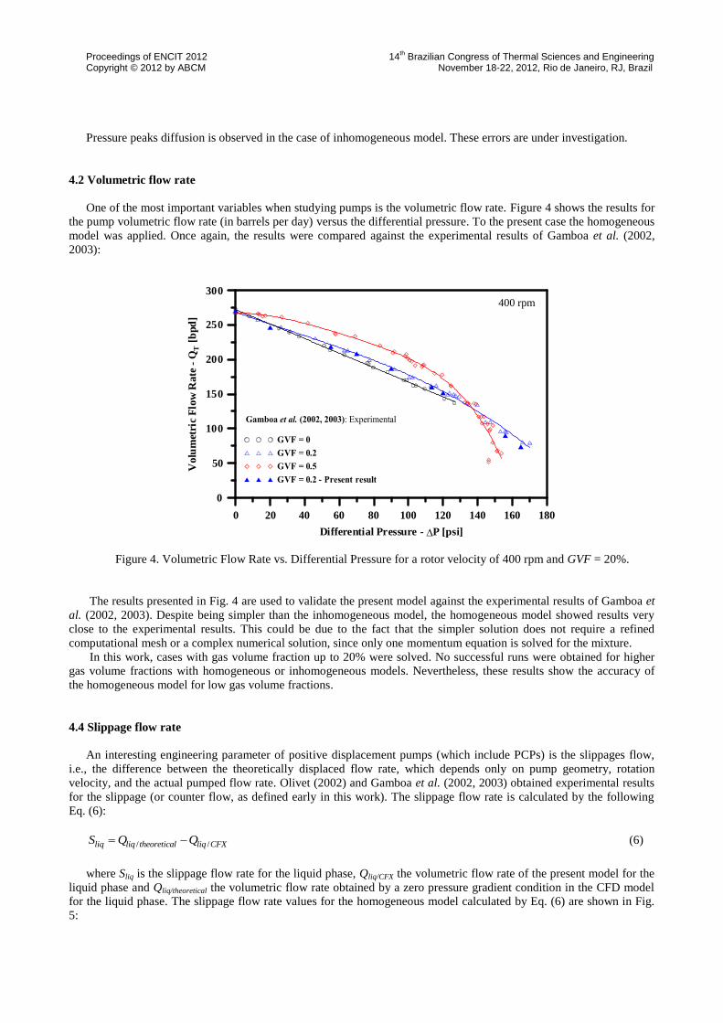
One of the most important variables when studying pumps is the volumetric flow rate. Figure 4 shows the results for
the pump volumetric flow rate (in barrels per day) versus the differential pressure. To the present case the homogeneous
model was applied. Once again, the results were compared against the experimental results of Gamboa et al. (2002,
2003):
0 20 40 60 80 100 120 140 160 180
Differential Pressure - DP [psi]
0
50
100
150
200
250
300
Vo
lum
etri
cF
low
Ra
te-
QT
[bp
d]
400 rpm
Figure 4. Volumetric Flow Rate vs. Differential Pressure for a rotor velocity of 400 rpm and GVF = 20%.
The results presented in Fig. 4 are used to validate the present model against the experimental results of Gamboa et
al. (2002, 2003). Despite being simpler than the inhomogeneous model, the homogeneous model showed results very
close to the experimental results. This could be due to the fact that the simpler solution does not require a refined
computational mesh or a complex numerical solution, since only one momentum equation is solved for the mixture.
In this work, cases with gas volume fraction up to 20% were solved. No successful runs were obtained for higher
gas volume fractions with homogeneous or inhomogeneous models. Nevertheless, these results show the accuracy of
the homogeneous model for low gas volume fractions.
4.4 Slippage flow rate
An interesting engineering parameter of positive displacement pumps (which include PCPs) is the slippages flow,
i.e., the difference between the theoretically displaced flow rate, which depends only on pump geometry, rotation
velocity, and the actual pumped flow rate. Olivet (2002) and Gamboa et al. (2002, 2003) obtained experimental results
for the slippage (or counter flow, as defined early in this work). The slippage flow rate is calculated by the following
Eq. (6):
/ /liq liq theoretical liq CFXS Q Q (6)
where Sliq is the slippage flow rate for the liquid phase, Qliq/CFX the volumetric flow rate of the present model for the
liquid phase and Qliq/theoretical the volumetric flow rate obtained by a zero pressure gradient condition in the CFD model
for the liquid phase. The slippage flow rate values for the homogeneous model calculated by Eq. (6) are shown in Fig.
5:

Proceedings of ENCIT 2012 14th Brazilian Congress of Thermal Sciences and Engineering
Copyright © 2012 by ABCM November 18-22, 2012, Rio de Janeiro, RJ, Brazil
0 20 40 60 80 100 120 140 160 180
Differential Pressure - DP [psi]
0
50
100
150
200
250
300
Sli
ppa
ge
Liq
uid
Flo
wR
ate
-S
L[b
pd
] 400 rpm
Figure 5. Slippage Liquid Flow Rate vs. Differential Pressure for a rotor velocity of 400 rpm and GVF = 20%.
The results presented in Fig. 5 are for the same conditions presented in Fig. 4, for the volumetric flow rate. The
homogeneous model presented good results also for the slippage flow rate, matching the experimental results. It is
noteworthy that the calculation of the slippage flow rate doesn’t include the gas phase. For the calculations the gas
volumetric flow rate was subtracted from the volumetric flow rate (QT) in order to obtain the slippage flow rate only for
the liquid phase.
4.4 Volumetric efficiency
Another important variable is the volumetric efficiency. For the PCP, as defined by Gamboa et al. (2002), the
volumetric efficiency is calculated as:
CFX
theoretical
Q
Q (7)
where η is the volumetric efficiency, QCFX the volumetric flow rate of the present model and Qtheoretical the volumetric
flow rate obtained by a zero pressure gradient condition in the CFD model. Olivet (2002) proposed a different approach
to the theoretical volumetric flow rate, obtaining it by an algebraic equation:
theoreticalQ V n (8)
where n the rotor velocity and V is the PCP displaced volume, obtained by the following Eq. (9) as the product of
the PCP free area (A) with the stator pitch (Pst):
24 8sr sr st
A
V D E Ew D w w P
(9)
The volumetric flow rate decreases with the increase of differential pressure (Fig. 4), hence the volumetric
efficiency will follow this behavior. To compare both methodologies, the volumetric efficiency obtained by Eq. (7) was
denominated η1 and the one considering the theoretical volumetric flow rate obtained by the Eq. (8), η2. In Tab. 2 are
presented the results for the volumetric efficiency, considering different pressure gradients and a gas volume fraction of
20%:

Proceedings of ENCIT 2012 14th Brazilian Congress of Thermal Sciences and Engineering
Copyright © 2012 by ABCM November 18-22, 2012, Rio de Janeiro, RJ, Brazil
Table 2. Volumetric efficiency for a GVF = 20% flow.
Differential Pressure (psi) η1 η2
55,07 83,83% 74,72%
113,46 59,15% 54,69%
120 56,13% 51,89%
156 33,25% 30,74%
165 27,29% 25,24%
The idea was to check the volumetric efficiency change with the gas volume fraction, but this was not possible
because of the problems with the turbulence model for high gas volume fractions. However, a comparison with the
single-phase flow model can show that the increase of the gas volume fraction, decrease the volumetric efficiency, as
can be found in Olivet (2002):
Table 3. Volumetric efficiency for single-phase flow.
Differential Pressure (psi) η1 η2
55,07 84,73% 78,48%
156 36,80% 34,02%
Comparing Tabs. 2 and 3, the single-phase flow presented a higher volumetric efficiency than the multiphase flow
as predicted by Gamboa et al. (2002, 2003) and Olivet (2002). The single-phase flow was solved taking into account the
multiphase flow model, developed in the present work, but with a gas volume fraction of 0%, i.e., the Eqs. (1) and (2)
were also solved to this model, considering the homogeneous model.
The difference between both approaches for the volumetric efficiency is noteworthy, with differences around 5%. In
order to compare both results, to the single-phase case, considering QCFX as the theoretical volumetric flow rate from η1
model (270 bpd, value from CFX), and Qtheoretical as the theoretical volumetric flow rate from η2 model (293 bpd, value
from Eq. (8)), according to Eq. (7) a volumetric efficiency of 92,15 % would be present in the flow, where the expected
was a 100 % volumetric efficiency.
In order to analyze the influence of the rotor velocity in the volumetric efficiency. Simulations considering the
homogeneous model with rotor velocities of 400, 300 and 200 rpm were run, maintaining the same gas volume fraction.
The results obtained and compared to the experimental results of Olivet (2002) are presented in Fig. 6:
0 20 40 60 80 100 120 140 160 180
Differential Pressure - DP [psi]
0
50
100
Vo
lum
etr
icE
ffic
ien
cy
-v
[%]
Olivet (2002): Experimental
400 rpm
300 rpm
200 rpm
400 rpm: Present Work
200 rpm: Present Work
300 rpm: Present Work
Figure 6. Volumetric Efficiency vs. Differential Pressure for different rotor velocities.
Proceedings of ENCIT 2012 14th Brazilian Congress of Thermal Sciences and Engineering
Copyright © 2012 by ABCM November 18-22, 2012, Rio de Janeiro, RJ, Brazil
The results showed the accuracy of the homogeneous model applied to the PCP. As can be viewed, when the rotor
velocity decreases, the volumetric efficiency also decreases. In other words, there’s a decrease in the theoretical flow
rate, accompanied by a volumetric flow decrease due to the differential pressure increasing, sharper as the rotor velocity
decreases. For both rotor velocities the results were satisfactory, showing precisely the decreasing in the volumetric
efficiency with the differential pressure increasing.
5. CONCLUSIONS
A multiphase flow model for a metallic stator PCP was developed and the results were validated against
experimental results. The complexity of solving such flow was detailed. The Eulerian-Eulerian approach was used and
the results for the homogeneous and inhomogeneous models were compared, showing the advantages and disadvantages
of both models in the multiphase flow modeling. The role of the turbulence model was made clear and this will be an
important point for further development of the model, to account for higher gas volume fractions.
Even with the difficulty to model the high gas volume fraction flows, this situation is barely found in oil fields
operations when using PCP as artificial lift method. Flows with gas volume fraction of 20% are considered to be “high
gas” flows.
The homogeneous model was successfully applied to solve the flow inside the PCP with volume fraction of 20%
and validated results were obtained for the pressure profile, for the volumetric flow rate, for the slippage flow rate and
for the volumetric efficiency. The inhomogeneous model showed some errors in the same conditions, which makes us
conclude that a more complex turbulence model have to be applied to it. Further investigation on this point is under run.
The PCP volumetric flow rate and slippage flow rate were correctly modeled for the homogeneous model. The
results obtained showed a small difference when compared to the experimental results for gas volume fractions of 20%.
The variations in the volumetric flow rate with the rotor velocity were analyzed and the results validated
experimentally.
The volumetric efficiency results, even for the homogeneous model, confirmed the statements of Gamboa et al.
(2002) and Olivet (2002), which the volumetric efficiency decreases with the increasing of gas volume fraction and
with the decreasing of the rotor velocity. The results were validated for rotor velocities of 200, 300 and 400 rpm.
The present model is the first attempt, after research in the literature, to model the multiphase flow for a metallic
stator PCP, and means the first step in the multiphase computational modeling of this artificial lift method, that is being
increasingly applied in onshore wells.
For future works we suggest developing a multiphase flow model for gas volume fractions of 50% and 80%, as
experimentally tested by Gamboa et al. (2002, 2003) and Olivet (2002). Hence, appropriate models for turbulence and
interfacial momentum transfer have to be implemented, in order to be applied to all range of gas volume fractions.
The present model can be extended for a positive interference PCP, to study the interactions between the elastomeric
stator and the multiphase flow. The effects of the heat transfer can be also included in the computational model and the
damages to the PCP caused by the heat can be studied.
6. ACKNOWLEDGEMENTS
The authors of this work would like to thank the Computational Mechanics Laboratory – LMC/UFRN and the
Computation Fluid Dynamics Laboratory – SINMEC/UFSC for the technical support, and also CAPES for the financial
support.
7. REFERENCES
Almeida, R. F. C., 2010. Simulação computacional da interação fluido-estrutura em bombas de cavidades progressivas.
MsC. Thesis. Universidade Federal do Rio Grande do Norte, Natal, RN, Brazil.
Assmann, B., 2008. Simulação, controle inteligente e sistemas especialista de dimensionamento de poços de petróleo
com elevação por bombeios de cavidades progressivas. PhD. Thesis. Universidade Federal do Rio Grande do Norte,
Natal, RN, Brazil.
Behzadi, A., Issa, R. and Rusche, H., 2003. “Modeling of dispersed bubble and droplet flow at high phase fractions”.
Chemical Engineering Science, Vol. 13, pp 759–770.
Bratu, C., 2005. “Progressing cavity pump (PCP) behavior in multiphase conditions”. In proceedings of the SPE
International Annual Technical Conference and Exhibition. Dallas, Texas, U.S.A.
Collier, J. G. and Tomme. J. R., 1935. Convective boiling and condensation. Oxford Engineering Science Series.
Proceedings of ENCIT 2012 14th Brazilian Congress of Thermal Sciences and Engineering
Copyright © 2012 by ABCM November 18-22, 2012, Rio de Janeiro, RJ, Brazil
Ekambara, K., Sanders, R., Nandakumar, K. and Masliyah, J., 2012. “CFD Modeling of Gas-Liquid Bubbly Flow in
Horizontal Pipes: Influence of Bubble Coalescence and Breakup”. International Journal of Chemical Engineering,
Vol. 2012, paper No. 620463
Gamboa, J., Olivet, A. and Espin, S., 2003. “New approach for modeling progressive cavity pumps performance”.
Paper presented at the SPE Annual Technical Conference and Exhibition. Denver, Colorado, USA, 5 – 8 October.
Gamboa, J., Olivet, A., González, P. and Inglesias, J., 2002. “Understanding the performance of a progressive cavity
pump with metallic stator”. Proceedings of the 20th
International Pump Users Symposium, USA.
Lima, J. A., Paladino, E. E., Almeida, R. F. C., Assmann, F. P. M., 2009. “Mesh generation for numerical simulation of
fluid-structure interaction within progressing cavity pumps”. 20th International Congress of Mechanical Engineering
— COBEM, Gramado/RS, Brazil, 15 – 20 November.
Maliska, C. R., 2004. Transferência de calor e mecânica dos fluidos computacional. 2nd edition. LTC.
Moineau, R., 1930. A new capsulism. PhD Thesis. Universitè de Paris, Paris, France.
Olivet, A., 2002. Estudio experimental del desempeño de uma BCP de estator rígido com flujo bifásico. PhD Thesis.
Universidad Simón Bolivar, Sartenejas, Venenezuela.
Olivet, A., Gamboa, J. and Kenyery, F., 2002. “Experimental study of two-phase pumping in a progressive cavity pump
metal to metal”, SPE77730, Paper presented at the SPE Annual Technical Conference and Exhibition. San
Antonio/TX, USA, 29 September – 2 October.
Paladino, E. E., Lima, J. A., Almeida, R. F. C. and Pessoa, P. A. S., 2011. “A computational model for the flow within
rigid stator progressing cavity pumps”. Journal of Petroleum Science and Engineering, Vol. 78, pp. 178 – 192.
Pessoa, P. A. S., 2009. Simulação computacional do escoamento em bombas de cavidades progressivas. MsC Thesis.
Universidade Federal do Rio Grande do Norte, Natal, RN, Brazil.
Sato, Y. and Sekoguchi, K., 1975. “Liquid velocity distribution in two-phase bubbly flow”. International Journal of
Multiphase Flow, Vol. 2, pp 79–95.
Schlichting, H., 1987. Boundary Layer Theory. McGraw-Hill, New York.
Winterton, R. and Munaweera, J., 2000. “Bubble size in two-phases gas-liquid bubbly flow in ducts”. Chemical
Engineering and Processing, Vol. 40, pp 437–447.
8. RESPONSIBILITY NOTICE
The authors are the only responsible for the printed material included in this paper.