a compressor designed for the energy research and development agency automotive gas turbine...
TRANSCRIPT
7/27/2019 A compressor designed for the energy research and development agency automotive gas turbine program.pdf
http://slidepdf.com/reader/full/a-compressor-designed-for-the-energy-research-and-development-agency-automotive 1/31
t
+
• ,.x
NASA THCHNICAL
MIMOFtANOUM
NASATM X- 71719
I
X
eaet
Z
(NRS_-T_-X-71719) A CONPRESSOR DESIGNED FO_TBE ENERGY RESEARCH AND DEVELOPMENT AGENCY
AUTOaOTIVE GAS TURBINE PROGRA_ (NASA) 32 p
HC $3°75 CSCL 21E
N75-2_116
Unclas
G3/;; 22206
A COMPRESSORDESIGNEDFORTHE ENERGY
RESEARCHAND DEVELOPMENTAGENCY
AUTOMOTIVEGAS TURBINE PROGRAM
, ,,j\
\g • , .._j... ... ._1
by Michael R. G,alvas
Lewis Research Center
U.S. Army Air Mobility R&D Laboratory
Cleveland, Ohio 44135
May 19"/5
........................................ ' :": .............. " :_..:_-_=-___""

7/27/2019 A compressor designed for the energy research and development agency automotive gas turbine program.pdf
http://slidepdf.com/reader/full/a-compressor-designed-for-the-energy-research-and-development-agency-automotive 2/31
i
i
ii_
J_
w)
I
ABSTRACT
A centrifugal compressor was designed for a gas turbine powered
automobile as part of the Energy Research and Development Agency pro-
gram to demonstrate emissions characteristics that meet 1978 standards
with fuel economy and acceleration which are competitive with con-
ventionally powered vehicles. A backswept impeller was designed for
the compressor in order to attain the efficiency goal and ran.qe
required for the objectives of this program. Details of the design
and method of flow analysis of the compressor are presented herein.
PRDCI'_DING PAGE BLANK NOT FILMED
:_.Reim m_""""_--'°_ ........... " ..... "........ " " • . "Pl "li'_,.'-_ ............. a ....
,

7/27/2019 A compressor designed for the energy research and development agency automotive gas turbine program.pdf
http://slidepdf.com/reader/full/a-compressor-designed-for-the-energy-research-and-development-agency-automotive 3/31
3
I
,,
'{i t • • L
f
SUMMARY
A centrifugal compressor was designed for a gas turbine powered
automobile as part of a program to demonstrate emissions characteristics
that meet 1978 standards with fuel economy and acceleration which are
competitive with conventionally powered vehicles. The selected design
point characteristics of the compressor are: mass flow rate, 0.59
kg/sec; rotative speed t 58,500 rpm; total pressure ratio_ 4.08; and
total efflciency_ .775. A backswept ;mpe|Ier was designed for the
compressor in order to attain the efficiency and operating range goals
of this program. Design Inlet Hach number for the diffuser was chosen__
to be 0.85 for additional operating range over that obtainable with
inlet Hath numbers closer to sonic. Downstream of the diffuser_ a
constant depth duct turns the flow from radial to axial. In the axial
sectlon_ constant height vanes remove the swirl before the flow enters
the regenerator Inlet. Details of the design and analysis of the
impeller_ dlffuser_ turning duct_ and deswlrl vanes are presented
herein.

7/27/2019 A compressor designed for the energy research and development agency automotive gas turbine program.pdf
http://slidepdf.com/reader/full/a-compressor-designed-for-the-energy-research-and-development-agency-automotive 4/31
! '''
INTRODUCTION
The Energy Research and Development Agency (ERDA)is
conducting a
program to demonstrate a gas turbine powered automobile that meets the
1978 Federal Emissions Standards with acceleration characteristics and
fuel economy that are competitive with current conventionally powered
vehicles. Part of this program involves vehicle and test stand evalu-
ations of an existing sixth generation engine manufactured by the
Chrysler Corporation. Another part of the program consists of the
design of a new engine to meet the objectives of the program with a
significant improvement in vehicle kilometers per llter.
The existing or "baseline _ engine delivers 112 KW in a 2000 K9
vehicte._ The new or "upgraded _l engine will delive- 75 KW in a 1600 K9
vehicle with the cepability of power augmentation to 90 KW through the
use of varlable guide vanes and water Injection at the compressor
inlet. Improved fuel economy w111 result from the reduced vehicl_
welgbt_, reduced power to weight ratlo_ increased turbine inlet tempera-
ture and possible improvements in component efflclencles. The aero-
dynamic components for the "upgraded a'engine have been designed at
the Lewis Research Center. These include the compressor_ the compressor-
drive turblne t the power turblne_ the duct between the turbines, and
*he power turbine exit diffuser. This report presents the details of
the aerodynamic design of the "upgraded" compressor.
The design mass flow rate for the "upgraded" compressor was 0.59
k9/sec. Reference i along with parametric studies indicates that stage
efficiency and flow ran9 e can be Improved by using a backswept Instead

7/27/2019 A compressor designed for the energy research and development agency automotive gas turbine program.pdf
http://slidepdf.com/reader/full/a-compressor-designed-for-the-energy-research-and-development-agency-automotive 5/31
5
of a radial impeller. Therefore_ a backswept configuration was selected
for the "upgraded" compressor to help attain the efficiency goal of this
program. The "upgraded" compressor design velocity diagrams and overali
geometry were selected on _he basis of e;31ne response and packaging
requirementst stress limitations and stage performance optimization
studies.
The following sections discuss the prellminary and detailed design
of the compressor together with the methods of calculation and assump-
tions used in the compressor design. Design point velocity diagrams
and state conditions are given for various stations throughout the
stage. The velocity diagrams are deduced from the effective flow
areas dictated by the assumed loss at the various stations. Blade
and vane geometry and surface vetocity distributions are given for the
impeller_ channel d|ffuser_ and deswlrl vanes. Also_ the wall velocity
distributions for the turning duct between the channel diffuser and
deswirl vanes are given.
""i"

7/27/2019 A compressor designed for the energy research and development agency automotive gas turbine program.pdf
http://slidepdf.com/reader/full/a-compressor-designed-for-the-energy-research-and-development-agency-automotive 6/31
6
PRELIMINARY DESIGN
As stated in the INTRODUCTION_ the net unaugmented power output
was 75 KW, This power level together with the pressure ratio (4.O8:1)_
the compressor turbine lniet temperature (1324 K)t estimated component
efficiencies and estimated parasitic a_d leakage losses were used to
determlt_e a First estimate of statepoints and mass flow along the
engine flow path using an engine cycle computer program. Using these
state points and mass fiow_ a compressor optimization study was made
using the loss model of reference 2 covering a range of rotative speeds
from 55_000 rpm to 70_000 rpm and a range of bacKsweep angles from
zero to 45 degrees. A minimum inducer hub diameter of 5.08 cm was
also specified to meet a constraint imposed by the starter clutch.
Other engine constraints such as gas generator acceleration time and
packaging as wel! as stress limitations were imposed to make the fln_]
configuration selection. Similar optimizations studies were executed
for the other components. F_al estimates were then made for a11
component efficiencies and other losses and used to make a final engine
cycle caicu|ation to obtain the design values of state points and flow
rate along the engine flow path.
The compressor design point mass flow is 0.59 kg/sec and the_
deslgn rotative speed is 58_500 rpm. Rotatlve speeds up to 30% higher
have compressor efflclencies up to one point higher than the selected
speed. However_ a stress limitatlon in the compressor turbine pre-
cluded the selection of a higher rotatlve speed. A peak stage
efficiency of 0.79 is considered to be achievable for the current
t
kr i:; i:r iil,I
7/27/2019 A compressor designed for the energy research and development agency automotive gas turbine program.pdf
http://slidepdf.com/reader/full/a-compressor-designed-for-the-energy-research-and-development-agency-automotive 7/31
1
state of the art.
7
Higher efflclencies are quoted In the literature
for this pressure ratio and flow rate. However3 considering the thick-
ness of the blades and the geometrical compromises required by the
method of fabrication_ it appears that a peak efficiency of 0.79 is a
realistic objective. An additional constraint on the compressor
design was that lts design point be 2 to )% from choke for the purpose
of improved Incidence and additional surge margin at part power
operation. This results in a design Point efficiency that is about
one point below the peak efficiency.
The upgraded compressor has a specific speed of .61. This value
ls the same as for the baseline compressor. Table ! gives a compari-
son of salient parameters for both compressors. The table shows that
a backsweep angle of 30 ° was selected for the upgraded design. This
selection was based on the best overall stage efficiency and flow
range. The selection of a backward curved design resulted in increased
gas generator acceleration time because of increased rotating inertia.
Increased inertia increases fuel consumption because of the nature of
the duty cycle for automotive engines. This nullifies some of the
benefits from efficiency gains obtained by the use of backward curva-
ture. Howevert the increase in flow range obtained with backward
curvature was sufficient to justify lts selection.
Some of the other parameters and geometry that were specified or
obtained in the optimization study and stage efficiency calculations
are the Inducer tip dlametert the number of impeller blades and an
associated work factor_ the ratio of Impeller exit-to-inducer tip
relative velocity ratlo and the vaneless diffuser radius ratio. An

7/27/2019 A compressor designed for the energy research and development agency automotive gas turbine program.pdf
http://slidepdf.com/reader/full/a-compressor-designed-for-the-energy-research-and-development-agency-automotive 8/31
_
,ii t• ,x"
8
Inducer tlp diameter of 8.95 cmwas selected which together with the
minimum hub diameter of 5.0_ cm results In an axial Mach number of
0.382.
Flfteen_ seventeen and eighteen blades were assumed in the pre-
liminary design. It is desired to have as few blades as possible to
minimize Inertia. The associated work factors (ratio of impeller _
exit absolute tangential velocity-to-Impeller exit blade speed) are
.7_66, .7548 and .7580 respectively. These Work factors are con-
sistent with conventional slip criteria. These work factors and the
se]ected rotative speed results in impeller eylt tip diameters of
16.76 cm, 16.70 cm and 16.64 cm. It should be noted that the selec-
tion of a larger number of blades reduces the tip diameter so that
the Increase In inertia due to more blades tends to be compensated
for by a reduced tip diameter. Eighteen blades were chosen for the
final design on the basis of tradeoffs between impeller ]oadings and
inertia.
The impeller exit-to-inducer tip relative velocity ratio was
selected to give an lmpeIler exit absolute flow angle of approximately
seventy degrees from radial This_was chosen so that during engine
accelerations the impeller exit flow angle wou]d not exceed 75 degrees.
Design values of abso]ute flow angle over 70 ° tend to limit compressor
flow range. Thls results from reduced radial momentum and Increased
flow path l_ngth In the vaneless space.
A vaneless diffuser at the impeller exit with a radius ratio o;
l. II was selected to give a vaned diffuser leading edge Mach number
of .85. This selection gives a peak stage efficiency somewhat lower
I ln l . . .. . .. . ,h, i i n nl nl I I

7/27/2019 A compressor designed for the energy research and development agency automotive gas turbine program.pdf
http://slidepdf.com/reader/full/a-compressor-designed-for-the-energy-research-and-development-agency-automotive 9/31
t _
9
than the optimum_ but provides additional operating range over that
obtainable with a higher diffuser leading edge Hach number. The loss
in stage performance is attributable to lower overall static pressure
recovery in the vaned diffuser caused by increased vaned diffuser
inlet blockage.
The estimated design point loss distribution is sun_narized In
Table 2. Other geometry not determined in the preliminary design
program were the overall channel dlffuser_ turning duct_ and deswlrl
vane,
The diffuser geometry was selected as follows: the diffuser
I
_
/
'I
.1
:!
!
\
f.
I
lnlet radius of 9.22 cm was dictated by the selection of the inlet
Nach number. The exit radius of 12.7 cm was selected because of
engine packaging requirements. A channel divergence angle of 13
degrees was selected for the design Inlet Mach number of 0.85 and
the calculated throat aerodynamic blockage of 9.0 percent.
D_ :=stream of the channel diffuser a constant depth turning duct
was chosen to guide the swirling flow from radlal to axial. The
inner radius of the duct was chosen to be twice the depth of the
duct. During the preliminary layout it was felt that the desired
velocity dlstributtons could be achieved if the inner wall radius-
re-duct depth ratio was less than 2.5.
Constant heigkt axial vanes were used to further diffuse the
flow before it enters the collector for entry Into the reg_t_erator.
Axial chord of the vanes was limited to 2.16 ¢m because of engine
packaging constraints.

7/27/2019 A compressor designed for the energy research and development agency automotive gas turbine program.pdf
http://slidepdf.com/reader/full/a-compressor-designed-for-the-energy-research-and-development-agency-automotive 10/31
iz
I0
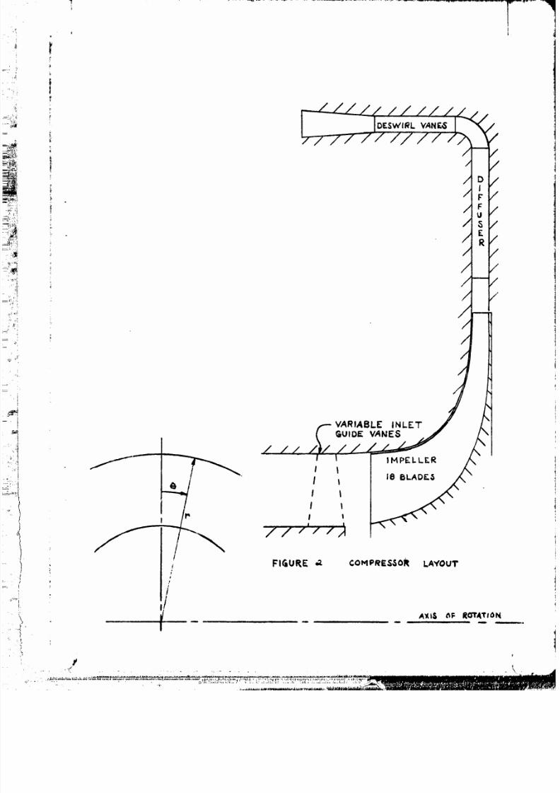
The flnal compressor path design velocity diagrams and state
conditions are shown in Figure 1. A meridiona] cross section of the
flow path is shown in Figure 2 and salient flow path dimensions are
tabulated in Table 3. The detalled design and flow calculations are
presented in the following section.
/
(
!
!i ......... "

7/27/2019 A compressor designed for the energy research and development agency automotive gas turbine program.pdf
http://slidepdf.com/reader/full/a-compressor-designed-for-the-energy-research-and-development-agency-automotive 11/31
j.
11
DETPl LED DESIGN
Impeller
The initial impeller meridional contour was constructed using
math_natical curves for the hub and shroud. An initial blade shape
was constructed by matching blade an9ies at the inlet and exit to
those required by part-power incidence :nd blade backsweep with
numerically smoothed curves between the endpoinLs. Near zero
Incidence from free stream to blade mean camber !_ne _]op9 the
lnducer span was specified at the design point to obtain more
favorable incidence and consequently_ additional surge margin at
part power operation. P meridional plane flow solution was obtained
using the computer program of reference 3. Iterations on m_rid|ona]
length_ meridional shap% and blade angle distribut|on were made
until the desired incidence and velocity distributions along the
blade surfaces were obtained. In the me¢idlonal analysis_ the
primary objectives were to obtain =lear-uniform loading along the
shroud mer|dlonal length with most of the diffusion occurring within
the inducer. High Initial diffusion was consldered acceptable
because the boundary layer is most able to withstand the adverse
pressure gradient without separating. Light diffusion along the
shroud downstream of the inducer was used In an attempt to minimize
the potential for flow separatlon_ which is most likely to occur
first at the shroud section. Velocity peaks and shroud suction sur-
face diffusion were also minimized to promote flow stability.
Detailed blade geometry and flow path Information output from
the flnal merldlonal plane solution were used _s input for a blade-
- '.L--t- I I ................. ! ..... III

7/27/2019 A compressor designed for the energy research and development agency automotive gas turbine program.pdf
http://slidepdf.com/reader/full/a-compressor-designed-for-the-energy-research-and-development-agency-automotive 12/31
,X
12
to-blade solution as described In reference 4. The flnal blade angle
distributions for the hubp mean and_tlp sections are shown In Figure
3_ and the blade surface velocity distributions from the blade-to-
blade solutlon for these three sections are shown in Figures 4a_ b_
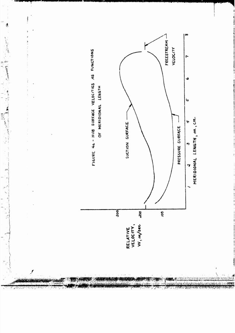
and c. Figure 4c shows that near uniform loading was achleved along
the shroud meridiona_ length with low diffusion outside the inducer
region. The requirements of zero incidence and uniform loading result
in some hlgh initial acceleration of the shroud suction surface
velocity near the leading edge. Attempts to furLher load the inducer
were considered undesirable because of severe acceleration and sub-
sequent diffusion of the suction surface velocity. The magnitude of
suction surface diffusion shown in the figure was considered to be
acceptable because tests of impellers in this pressure ratio and
flow range_ operating at this incidence_ indicate penalties of only
about one point in efficiency. The three figures also show that
other than the inducer there are no severe local velocity gradients
that could cause separation,
Channel Diffuser
The primary considerations in the detalled design of the channel
diffuser were incidence for adequate surge margin and throat area
required for the design point mass flow. Parallel endwalls down-
stream of the impeller were used throughout the diffusing system.
The wail spacing was equal to the lmpeller exlt blade height plus
the axial clearance at the Impeller exit. Results of the preliminary
design Indicated that the absolute flow angle at the channel diffuser
leading edge was 70.3 degrees from radial. Four degrees negative

7/27/2019 A compressor designed for the energy research and development agency automotive gas turbine program.pdf
http://slidepdf.com/reader/full/a-compressor-designed-for-the-energy-research-and-development-agency-automotive 13/31
,, ,,i;
,,d<
_h_
"°'I
13
incidence to the channel diffuser mean line settin 9 angle was con-
sidered desirable from a surge margin standpoint. Thls resulted in
a vane mean line setting angle of 74.3 de9rees from radial. Empiric_l
correlations (reference 5) based on impeller exlt absolute Mach number
and vaneless diffuser static pressure rlse indicated that 9.0 percent
ae_odynamlc blockage could be expected at the channel diffuser inlet.
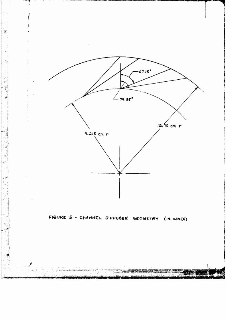
Several diffuser configurations with various numbers of vanes were
constructed using this setting angle but it was found that the diffuser
would be choked when the anticipated aerodynamic b|ockage was included
in the inviscld flow calculations. In order_o provide addltional
throat area the incidence angle was compromised and the vanes were
rotated toward radial. The final diffuser configuration had fourteen
vanes with a inean line setting angle of 73.5 degrees from radial.
This satisfied the throat area requirement and still provided negative
incidence for surge margin. Channel divergence of l_ degrees was
selected to give maximum static pressure recovery for the length
available. The data of reference 6 for throat aspect ratios of O. 25
were used for the design inlet Mach number and throat blockage in
making this selection. Channel divergence angles of 12 ° to 1_"
result in maximum static pressure recovery when the diffuser overall
length-to-inlet width ratio ls optimized. Although this channel
diffus,r is considerably shorter than optimum because of the engine
packaging constralnt_ l) ° divergence was selected in an attempt to
maximize static pressure recovery within the arab|able length. A
radial plane view of the channel diffuser is shown in Figure 5. The
blade-to-blade surface velocity distribution for the channel diffuser

7/27/2019 A compressor designed for the energy research and development agency automotive gas turbine program.pdf
http://slidepdf.com/reader/full/a-compressor-designed-for-the-energy-research-and-development-agency-automotive 14/31
f 14
is shown in Figure 6. The figure shows maximum loading just inside
the channel diffuser leadin 9 edge with progressively decreasing load-
ing along the merldional length.
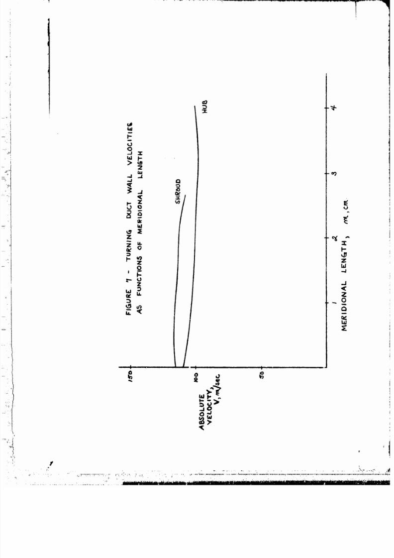
Turning Duct
The turning duct geometry is completely specified by two circular
arc surfaces of revolution. The inner wall radius is 0.852 cm and
the outer wall radius is 1.27_ cm. The inlet annulus is located at
a radius of 12.7 cm from the axis of rotation. Inlet stat. conditions
are those which correspond to the exit of the channel diffuser.
Approximately 37.5 degrees of swirl remains in the flow just inside
the channel at the diffuser exit. Rapid expanslon_ assumed to occur
at constant total pressure_ oround the channel diffuser trailing
edges results in an absolute flow angle of about 57' from radial.
I
i
Angular momentum remains relatively constant throughout the turning
duct although some diffusion and reduction of the t_.gential velocity
is achieved through the slight increase in the duct mean sJ:reamline
radius, The flow solution for the turning duct was computed using
the merldional plane analysis of reference 3. The velocity distri-
butions along the hub and shroud are shown in Figure 7.
Oeswirl Vanes
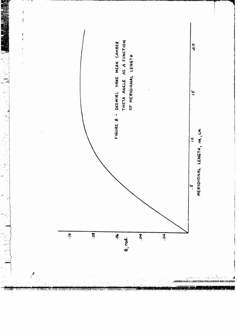
Sixty constant height axial vanes are used to remove the swirt
remaining in the flow before it enters the collector for the regenerator
inlet. The number of vanes was selected primarily on the basis Gf
solidity. Axial chord was limited to 2,16 cm for engine packaging.
Several mean camber line angle distributions investigating various
rates of turning were studied in the design, Approximately three

7/27/2019 A compressor designed for the energy research and development agency automotive gas turbine program.pdf
http://slidepdf.com/reader/full/a-compressor-designed-for-the-energy-research-and-development-agency-automotive 15/31
!
15
degrees of negative incidence were used to control suction surface
diffusion, Eight degrees deviation at the trailing edge resulted in
axial flow, The final mean camber line angle distrlbution_ shown In
Figure 8_ has the maximum curvature just upstream of the mld-axlal
chord. Past experience indicates that this type of distribution
gives favorable results. A .152 cm constant thickness vane was
overlald on this mean camber line. The blade-to-bladz surface velocity
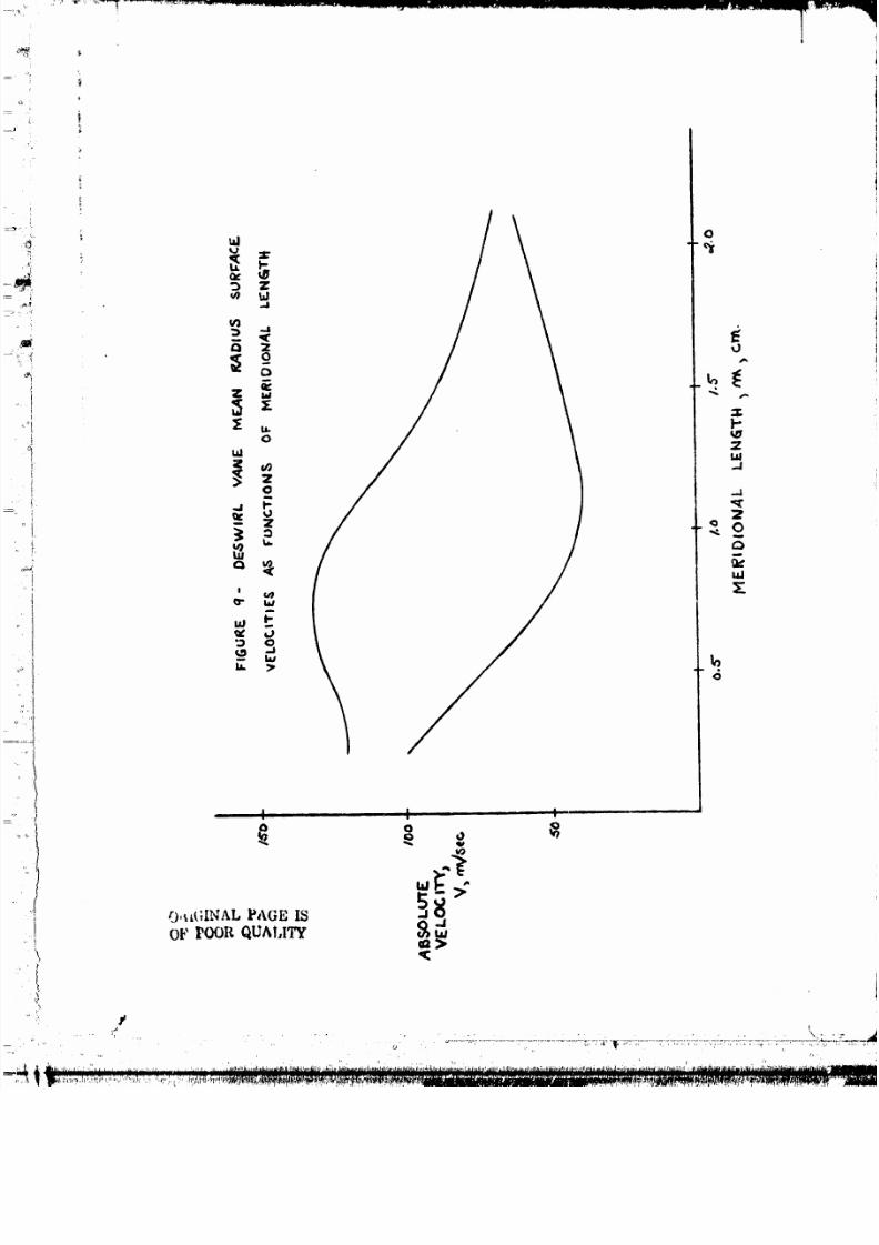
distribution for the deswirl vanes is shown in Figure 9. The figure
shows maximum loading just upstream of the mid-axial chord with rapid
suction surface diffusion and 11ght loading near the trailing edge.
t

7/27/2019 A compressor designed for the energy research and development agency automotive gas turbine program.pdf
http://slidepdf.com/reader/full/a-compressor-designed-for-the-energy-research-and-development-agency-automotive 16/31
6 ...............................
SYMBOLS
s'
m
M
pn
r
Rc
T u
g
V
W
W
o_
B
Subscripts:
U
m
mer|dional length_ cm
Hach number
total pressure_ N/cm 2
radlus_ cm
total pressure ratio
total temperature_ K
blade speed_ m/see
absolute velocity 3 m/sec
mass flow rate 2 kg/sec
relative velocity_ m/sec
absolute flow angle_ deg from meridional
relative flow angl% de 9 from meridional
ratio of total pressure to standard sea-level total
pressure
incremental quantity
total efficiency
relative angular coordinate defined in Figure 2
ratio of total temperature to standard sea-level
total temperature
tangential direction
mer_dtona| direction
........... . . . (
7/27/2019 A compressor designed for the energy research and development agency automotive gas turbine program.pdf
http://slidepdf.com/reader/full/a-compressor-designed-for-the-energy-research-and-development-agency-automotive 17/31
e
17
REFERENCES
1. Weigel_ Carl; Ball_ Calvin L.; and Tysl_ Edward_R.: Overall Per-
formance in Argon of a 16.4-Centimeter (6./d_-ln.) Sweptback-
Bladed Centrifugal Compressor. NASA TM X-2269.
2. Galvas_ Michael R.: Fortran Program for Calculating Total-Effi-
ciency-Specific Speed Characteristics of Centrifugal Compressors.
NASA TM X-2594_ 1972.
3. Katsanls_ Theodore; and McNally3 William D.: Fortran Program for
Calculating Velocltles and Streamlines on the Hub-Shroud Mid-
Channel Flow Surface of an Axial- or Mixed-Flow Turbomachine.
NASA TN D-7343_ 1973.
4. Katsanis, Theodore: Fortran Program for Calculating Transonic
Velocities on a Blade-to-Blade Stream Surface of a Turbomachine.
NASA TN D-5427_ 1969.
5. Kenny_ D. P.: A Comparison of the Predicted and Measured Per-
formance of High Pressure Ratio Centrifugal Compressor Diffusers.
ASME Paper 72-GT-54.
6. Runstadler_ Peter W._ dr.: Pressure Recovery Performance of
Straight-Channel_ Single-Plane Divergence Diffusers at High
Mach Numbers. USAAVLABS Technical Report 69-56, 1969.

7/27/2019 A compressor designed for the energy research and development agency automotive gas turbine program.pdf
http://slidepdf.com/reader/full/a-compressor-designed-for-the-energy-research-and-development-agency-automotive 18/31
.
t
"C
TAELF... I -- COMPARI_0N OF COMPRE,_$OR_
MASS FLOW RATE
,.,.,.,T_/_, i<_/sec
PRESSURE RATIO
RO'TATIVE SPEED _rpm
EFFICIENCY',
IMPELLER BLADIN_
.SPECIFIC ,SPEED
8,_E 1.t,NE.
t.03
_-.OI
_ H.(,,0
."/1'1
RADIAL
0.61
UPGRADED
O.&l
_.O'g
585OO
.17_"
O.61
TAI_ LE _.. ¢OlVIpREsSo R L0_£ I)I S1" I_'_IUTION
LGS_ C_.-iENERATOREFFICIENCY DE.CRE' MENT Z_
I

7/27/2019 A compressor designed for the energy research and development agency automotive gas turbine program.pdf
http://slidepdf.com/reader/full/a-compressor-designed-for-the-energy-research-and-development-agency-automotive 19/31
f
i tn
"I'_I3L E ,_ COMPRESSOR GEOME'TKY
INDUCER HUB DIAWtE'rE.R ,, cm. ,,.¢.0_
iNDUCER -riP OIAt_E'TER, on1. $.q5
INDUCER RADIAL CLEARANCE ,Era. ._b,2_"
I MPELLEK AV, IAL LEN&TH _ Gin. 3.'/5
IMPELLER EXYT DIAMETER _Cm. l_.6_.
IMPELLER EXI"T BACK,_WEEP._ cle_ _'rorq ra_'QJ
IMPELLER EXt"r BLADE HEIGHT _ crv_.
.I PtPELLE R.
i
DIFFUSER'
EXIT. AW,IA k CLEARAk_CE , cry. . o-_.¢
DF-.P_H _ Cm. .,q_6
DIFFU,_ER INLET DIANE1fER _ C.,,r_. I'_.q.3
D_FFU,_ER EXiT DIAMETER ,¢nt. =2_'.'q.O
"I'URNIN6 DUCT INNER WALL RADIU_ _ c_. ._;_L
"TURN ING DUCT ou'rER WALL lCADIb_S_ Gin.
DE_VIRL VANE. HEIGHT _ CPA.
ii i
DESWIRL VANE AXIAL CI_RD _ cry.
i. a'tcl
. ,,._, ,'__.'_AL PAGB IS
UF I_OR QUALITY

7/27/2019 A compressor designed for the energy research and development agency automotive gas turbine program.pdf
http://slidepdf.com/reader/full/a-compressor-designed-for-the-energy-research-and-development-agency-automotive 20/31
,--
_',
I
?
IMPELLER _/ELOCITY DIAGRAMS
I NL "E.T
°
V=
U..= P5"5".6
HUB
W- 304-. ?
TIP
f_
T': 8_.I_ K
EXrT MEAN
__c< =70. _"
,__W= l_i. 6
Vu.: 886._3
FI&URE t - DESIGN POINT V£_.O¢ll"Y DIAGRAMS

7/27/2019 A compressor designed for the energy research and development agency automotive gas turbine program.pdf
http://slidepdf.com/reader/full/a-compressor-designed-for-the-energy-research-and-development-agency-automotive 21/31
, I
,
ti
i
1
-i
V'nm: IIq. I
DIFFUSER VELOC I'rY DIA6RAMS
I
INLET
TURNING DUCT VELOCIT'Y DIAG_I.I,AM$
MEAN _'rKEAM LI_F.
ORIGINAL PAGE IS
OF POOR OUALITY
7/27/2019 A compressor designed for the energy research and development agency automotive gas turbine program.pdf
http://slidepdf.com/reader/full/a-compressor-designed-for-the-energy-research-and-development-agency-automotive 22/31
I
!
VARIABLE INLETGUIDE VANES
/
I
/
/ |
I
I
I
t
IMPELLER
!
/////,_
f
i
I
FIGURE .z COHPRE$30R LAYOUT
AXI$ (IF Ro'rATION

7/27/2019 A compressor designed for the energy research and development agency automotive gas turbine program.pdf
http://slidepdf.com/reader/full/a-compressor-designed-for-the-energy-research-and-development-agency-automotive 23/31
J
I
\
ORIGINAL PAG_ IS
OF POOR QUALITY
I-",,,..q
...2
Z
m
7/27/2019 A compressor designed for the energy research and development agency automotive gas turbine program.pdf
http://slidepdf.com/reader/full/a-compressor-designed-for-the-energy-research-and-development-agency-automotive 24/31
'

7/27/2019 A compressor designed for the energy research and development agency automotive gas turbine program.pdf
http://slidepdf.com/reader/full/a-compressor-designed-for-the-energy-research-and-development-agency-automotive 25/31

7/27/2019 A compressor designed for the energy research and development agency automotive gas turbine program.pdf
http://slidepdf.com/reader/full/a-compressor-designed-for-the-energy-research-and-development-agency-automotive 26/31
,J
f
Z
_ Q
I 13
//
/D
U
D
W
OR'_!!INAL PAGm ,o
uu_t QUALITy
_J
0I
r_I
X
7/27/2019 A compressor designed for the energy research and development agency automotive gas turbine program.pdf
http://slidepdf.com/reader/full/a-compressor-designed-for-the-energy-research-and-development-agency-automotive 27/31
_ , + +. . .
1

7/27/2019 A compressor designed for the energy research and development agency automotive gas turbine program.pdf
http://slidepdf.com/reader/full/a-compressor-designed-for-the-energy-research-and-development-agency-automotive 28/31
a n _ n i
ORIGINAL PAGE IS o
OF POOR QUALITY _t
!
O
y.,t
I
O
NF_m
0:!
v_
b-
Z
..,,I
.J_C2
=E
7/27/2019 A compressor designed for the energy research and development agency automotive gas turbine program.pdf
http://slidepdf.com/reader/full/a-compressor-designed-for-the-energy-research-and-development-agency-automotive 29/31
_2:3
>_
t- u
I| -- ,
O.a
.(
_9
l-
Zi,i...I
.J,(Z0
m
tu:E
I
I
......... ......................:...:............................ ..... IIII_F
I_1
7/27/2019 A compressor designed for the energy research and development agency automotive gas turbine program.pdf
http://slidepdf.com/reader/full/a-compressor-designed-for-the-energy-research-and-development-agency-automotive 30/31
: /0
[ I I
7/27/2019 A compressor designed for the energy research and development agency automotive gas turbine program.pdf
http://slidepdf.com/reader/full/a-compressor-designed-for-the-energy-research-and-development-agency-automotive 31/31
<)
t,.
!C_
_" L,./m
r_ .=;
I , I ..... !
0
p-
tel..J
O
uJ