a complex event processing framework …
TRANSCRIPT

A COMPLEX EVENT PROCESSING FRAMEWORK IMPLEMENTATION USING
HETEROGENEOUS DEVICES IN SMART ENVIRONMENTS
A THESIS SUBMITTED TO
THE GRADUATE SCHOOL OF INFORMATICS INSTITUTE
OF
THE MIDDLE EAST TECHNICAL UNIVERSITY
BY
MUAMMER ÖZGE KAYA
IN PARTIAL FULFILLMENT OF THE REQUIREMENTS FOR THE DEGREE OF
MASTER OF SCIENCE
IN
THE DEPARTMENT OF INFORMATION SYSTEMS
JANUARY 2012

A COMPLEX EVENT PROCESSING FRAMEWORK IMPLEMENTATION
USING HETEROGENEOUS DEVICES IN SMART ENVIRONMENTS
Submitted by M. ÖZGE KAYA in partial fulfillment of the requirements for the
degree of Master of Science in Information Systems, Middle East Technical
University by,
Prof. Dr. Nazife Baykal
Director, Informatics Institute
Prof. Dr. Yasemin Yardımcı Çetin
Head of Department, Information Systems
Assist.Prof.Dr. P. Erhan Eren _______
Supervisor, Informatics Institute
Examining Committee Members:
Assoc. Prof. Dr. Sevgi Özkan
IS, METU
Assist.Prof.Dr. P. Erhan Eren
IS, METU
Assist.Prof.Dr. Aysu Betin Can
IS, METU
Dr.Nail Çadallı
KAREL A.Ş.
Assoc. Prof. Dr. Altan Koçyiğit ____
IS, METU
Date: 30.01.2012

iii
I hereby declare that all information in this document has been obtained and presented
in accordance with academic rules and ethical conduct. I also declare that, as required by
these rules and conduct, I have fully cited and referenced all material and results that are
not original to this work.
Name, Last name : Muammer Özge Kaya
Signature : __________________

iv
ABSTRACT
A COMPLEX EVENT PROCESSING FRAMEWORK IMPLEMENTATION USING
HETEROGENEOUS DEVICES IN SMART ENVIRONMENTS
Kaya, Muammer Özge
M.S. , Department of Information Systems
Supervisor: Assist.Prof.Dr. P. Erhan Eren
January 2012, pages 83
Significant developments in microprocessor and sensor technology make wirelessly
connected small computing devices widely available; hence they are being used frequently
to collect data from the environment. In this study, we construct a framework in order to
extract high level information in an environment containing such pervasive computing
devices. In the framework, raw data originating from wireless sensors are collected using an
event driven system and converted to simple events for transmission over a network to a
central processing unit. We also utilize complex event processing approach incorporating
temporal constraints, aggregation and sequencing of events in order to define complex
events for extracting high level information from the collected simple events. We develop a
prototype using easily accessible hardware and set it up in a classroom within our
university. The results demonstrate the feasibility of our approach, ease of deployment and
successful application of the complex event processing framework.
Keywords : Complex Event Processing, Rule Engine, Wireless Sensor Networks, Pervasive
Computing, Event Driven Architecture
v
ÖZ
AKILLI ORTAMLARDA HETEROJEN CİHAZLAR KULLANARAK KARMAŞIK OLAY İŞLEME UYGULAMA ÇATISI GERÇEKLEŞTİRİLMESİ
Kaya, Muammer Özge
Yüksek Lisans, Bilişim Sistemleri Bölümü
Tez Yöneticisi: Yard.Doç. Dr. P. Erhan Eren
Ocak 2012, sayfa 83
Mikroişlemci ve algılayıcı teknolojisindeki önemli gelişmeler kablosuz bağlantılı küçük bilişim
cihazlarının kolayca bulunabilmesine imkan sağladı; bu yüzden bir ortamdan veri toplanması
için bu cihazlar sıklıkla kullanılmaya başlandı. Bu çalışmada, bu tip yaygın bilişim cihazlarının
bulunduğu bir ortamdan yüksek seviye bilgi çıkarımı yapmak için bir uygulama çatısı
geliştiriyoruz. Bu uygulama çatısında, kablosuz algılayıcıların elde ettiği ham veri olay tetikli
bir sistem ile toplanıyor ve bir ağ üzerinden merkezi işleme birimine gönderilmek üzere
basit olaylara çevriliyor. Ayrıca bu basit olaylardan yüksek seviyede bilgi çıkartmak için
zamansal kısıtlamalar, kümeleme ve olayların sıralanması gibi özellikleri içeren karmaşık
olay işleme yaklaşımını kullanıyoruz. Kolayca erişilebilen donanımı kullanarak bir prototip
geliştiriyoruz ve onu üniversitemiz içerisinde bir sınıfa yerleştiriyoruz. Sonuçlar
yaklaşımımızın yapılabilirliğini, kolay konumlandırılmasını ve karmaşık olay işleme uygulama
çatısının başarıyla uygulandığını göstermektedir.
Anahtar Kelimeler : Karmaşık Olay İşleme, Kural Motoru, Kablosuz Algılayıcı Ağları, Yaygın
Bilişim, Olay Tetikli Mimari

vi
ACKNOWLEDGMENTS
I express sincere appreciation to my supervisor Assist.Prof.Dr. P. Erhan Eren for his
guidance and insight throughout the research.
The institute and my research assistant friends deserve special thanks for all the help they
have provided during the implementation of hardware components of the system. I would
also like to present my thanks to my lab friend Bilgin Avenoğlu for all the work he has done
to establish the “Wireless Lab” and for his unending help and support throughout my thesis
research.
I also would like to my colleagues Alper Çevik and Yusuf Sayıta for covering me at work
while I was busy with my thesis. My thanks also go to my employers who were always
understanding and provided me time for my thesis research.
My deepest thanks belong to my family, who were always by my side, for giving me the
best study environment and for always believing in me. I would like to thank my sister and
her husband for making my life bearable during this study. I would also stress my gratitude
to my grandmother who was always praying for my success.

vii
DEDICATION
To my grandma

viii
TABLE OF CONTENTS
ABSTRACT ................................................................................................................................. iv
ÖZ .............................................................................................................................................. v
ACKNOWLEDGMENTS .............................................................................................................. vi
DEDICATION ............................................................................................................................ vii
TABLE OF CONTENTS .............................................................................................................. viii
LIST OF TABLES .......................................................................................................................... x
LIST OF FIGURES ....................................................................................................................... xi
CHAPTER
1 INTRODUCTION ..................................................................................................................... 1
1.1 Background .................................................................................................................... 1
1.2 Outline............................................................................................................................ 3
2 LITERATURE REVIEW ............................................................................................................. 4
2.1 Wireless Sensor Networks ............................................................................................. 4
2.2 Event Detection and Complex Event Processing ........................................................... 6
2.3 Event Processing on Wireless Sensor Networks ............................................................ 8
2.4 Applications Areas........................................................................................................ 11
3 COMPLEX EVENT PROCESSING FRAMEWORK .................................................................... 15
3.1 Framework Overview ................................................................................................... 16
3.1.1 Conceptual Design ................................................................................................ 16
3.1.2 Complex Event Processing .................................................................................... 17
3.2. Software Components ................................................................................................ 19

ix
3.2.1. Event Sources ....................................................................................................... 20
3.2.2. Event Channel ...................................................................................................... 22
3.2.3. Event Processing .................................................................................................. 23
3.3. Hardware Components ............................................................................................... 26
3.3.1. Design of Sensor Boards ...................................................................................... 27
3.3.2. Coding with Sensor Boards .................................................................................. 34
3.3.3. Communication Interface .................................................................................... 35
4 PROTOTYPING AND REAL LIFE APPLICATION ...................................................................... 38
4.1. Classroom Environment Setup .................................................................................... 38
4.1.1 Software Setup ...................................................................................................... 40
4.1.2 Hardware Setup .................................................................................................... 41
4.2. Complex Events and Rules .......................................................................................... 47
4.3 Results and Discussion ................................................................................................. 50
4.3.1. Prototyping .......................................................................................................... 50
4.3.2. Real Life Application ............................................................................................. 53
4.3.3. Discussion ............................................................................................................. 57
5 CONCLUSION ....................................................................................................................... 60
5.1 Summary of Study ........................................................................................................ 60
5.2 Future Work ................................................................................................................. 63
REFERENCES ........................................................................................................................... 65
APPENDICES
Appendix A : Sensor Board Schematic For Arduino Uno .................................................. 70
Appendix B : Microcontroller Codes ................................................................................. 71
Appendix C : Rules in Drools Rule Language ..................................................................... 77

x
LIST OF TABLES
Table 3.1- Sensor Type Characters Used In Messages ........................................................... 20
Table 3.2-Summary Information about Arduino Uno ............................................................ 27
Table 4.1- System Information of Computers Used in Implementation ................................ 39
Table 4.2- Sensor Usage Details ............................................................................................. 42
Table 4.3- Decisions for the Classroom .................................................................................. 48
Table 4.4- Complex Event Detection Times ........................................................................... 56

xi
LIST OF FIGURES
Figure 2.1- EP Reference Architecture. .................................................................................... 6
Figure 2.2- High Level Architecture of Study. .......................................................................... 9
Figure 2.3- Physical and semantic data flow in RFID-enabled hospital ................................. 11
Figure 2.4- The Components of a Smart Environment. ......................................................... 12
Figure3. 1 – Conceptual Design.............................................................................................. 17
Figure 3.2 – CEP Engine Modules ........................................................................................... 18
Figure3. 3 – EDA System Diagram .......................................................................................... 19
Figure 3.4 Class Diagram for SensorToJMS component ........................................................ 21
Figure 3.5 Class Diagram for StaticEventGenerator component ........................................... 22
Figure 3.6 – Temporal Relations between Events ................................................................. 24
Figure 3.7 – Class diagram for JMSToSensor Component ..................................................... 26
Figure 3.8- Hall Effect Sensor (US1881) Connection on Development Board ....................... 28
Figure 3.9- Infrared Proximity Sensor (Sharp) Connection on Development Board ............. 29
Figure 3.10- Optical Detector (QRD1114) Connection on Development Board .................... 30
Figure 3.11- PIR Motion Sensor (SE-10) Connection on Development Board ....................... 31
Figure 3.12-Photoresistor Connection on Development Board ............................................ 32
Figure 3.13 - Electret Microphone Connection on Development Board ............................... 32
Figure 3.14 - Temperature Sensor Connection on Development Board ............................... 33
Figure 3.15 – Microcontroller Network Schema .................................................................... 36
Figure 4.1 – Messaging between components ...................................................................... 40
Figure 4.2 – Microcontrollers Schematic ............................................................................... 42
Figure 4.3 – Microcontroller Setup - Door ............................................................................. 43
xii
Figure 4.4 – Microcontroller Setup –Outside ........................................................................ 44
Figure 4.5 – Microcontroller Setup –Inside, Wall .................................................................. 45
Figure 4.6 – Microcontroller Setup –Inside, Ceiling ............................................................... 46
Figure 4.7 - Redbee RFID Reader ........................................................................................... 46
Figure 4.8- Prototype Implementation In Wireless Lab-Ceiling ............................................. 51
Figure 4.9- Prototype Implementation on the Wireless Lab-Door ........................................ 52
Figure 4.10- Prototype Implementation In Classroom-Wall .................................................. 54
Figure 4.11- Prototype Implementation in the Classroom-Door ........................................... 54
Figure 4.12- Webpage showing the results of event processing ........................................... 56
Figure 4.13- Number of Events for Five Days of Measurement ............................................ 58
Figure 4.14- Noise Level Measurement in the Classroom ..................................................... 59
Figure 5.1- Hardware Cost of the Framework ....................................................................... 61

xiii
LIST OF ABBREVIATIONS
ADC Analog to Digital Converter
AJAX Asynchronous JavaScript and XML
API Application Programming Interface
BRMS Business Rule Management System
CE Complex Event
CEP Complex Event Processing
DRL Drools Rule Language
ECA Event-Condition-Action
EDA Event Driven Architecture
EPTS Event Processing Technical Society
I2C Inter-Integrated Circuit
IDE Integrated Development Environment
IR Infrared
JMS Java Message Service
LAN Local Area Network
MOM Message-Oriented Middleware
PIR Passive Infrared
RFID Radio Frequency Identification
SQL Structured Query Language

xiv
USB Universal Serial Interface
WSN Wireless Sensor Networks
WSAN Wireless Sensor and Actor Networks

1
CHAPTER 1
INTRODUCTION
Pervasive computing, also referred to as ubiquitous computing, has become popular with
many mobile devices and computing units being used widely in our daily lives. With the
help of new wireless communication technologies most of these devices have the capability
to communicate with each other. Such networked computing devices let the users access
data anywhere, anytime.
1.1 Background
Mark Weiser defines [1] three different era for computing technology; main frame
computing era where one computer is used by many users, personal computing era where
one computer is used by one person and pervasive computing era where one user uses
many computers. A person can use the computers knowingly or can interact with
embedded devices unknowingly. Weiser also states that these computing units shall
become hidden until they become totally invisible to users [2]. Hidden devices monitoring
their environments and other computing units together can provide significant information
to users. The ease of access to data and using microcontrollers on everyday objects initiate
the pervasive computing application development. With pervasive computing we can
construct intelligent objects, context-aware spaces and smart environments.
When current technology was not available, pervasive computing was Weiser’s vision, but
today developments in computing technology have made it a much more viable research

2
area. There are still missing pieces to obtain a complete pervasive environment but new
computing approaches help us to progress towards it. In this study, we construct a
pervasive computing framework and for this we use currently available technology to test
its feasibility. We want to provide a complete framework that collects data and processes
them to obtain higher level information. We use Complex Event Processing paradigm to
obtain a smart environment with help of a Wireless Sensor Network (WSN).
Wireless Sensor Network (WSN) technology is beneficial to provide an infrastructure that
supports heterogeneous devices and wireless connection between them. Wireless Sensor
Networks are basic networks where more than one sensor is gathering data and
transmitting it through a wireless medium. Gathering environmental data and monitoring a
physical location are mostly done by WSN’s in recent research studies. Usually sensor nodes
in a WSN consist of a sensor, processor, transmitter and a power unit. The data from these
sensor nodes are transferred wirelessly to a sink node. This sink node acts as a gateway for
the other components of the system where further processing is done on the collected
data. WSN’s are densely deployed and do not have a fixed topology; the nodes transmit
data with multi-hop so that even if one of the nodes fails, the network still continues to
work correctly. There are ongoing researches for deployment, routing and other
networking problems related to WSN’s; on the other hand the researches about pervasive
applications use sensor nodes that are communicating wirelessly. Most of the current
pervasive computing applications use sensor networks but not all of them utilize these
characteristics of WSN’s. We also use a network of sensors but the topology of the network
is predefined and sensor nodes are communicating only with the sink node.
In pervasive computing, data gathered in an environment must be processed and converted
to meaningful information in order to obtain a smart environment. Event processing is an
approach generally used in event driven systems where computing is done over the simple
events gathered from various sources. In real life there are events that can be represented
as a set of other simple events which are called Complex Events. While event processing is
simply gathering, filtering and analyzing simple events, Complex Events need more
processing to be extracted. The events forming a complex event mainly have conjunctions,
disjunctions, sequences or temporal relationships with each other. The technology to
deduce them is called Complex Event Processing (CEP). Traditional event processing only
deals with simple events and gets basic information on those events. With CEP it’s possible
to gather more meaningful events happening in an environment, and high level information
is essential in order to develop pervasive computing applications.

3
1.2 Outline
The aim of this study is to implement an event driven system in a classroom environment
and to extract meaningful information from the raw data collected by the deployed
sensors, by using Complex Event Processing. The availability of current technology for the
purpose of making our environments smarter will be discussed.
This chapter provides background information regarding Wireless Sensor Networks and
Complex Event Processing which are used for pervasive computing scenarios for smart
environments. Chapter 2 gives more information about these technologies and applications
that use them by providing a review of previous work and related literature. Chapter 3
presents the design of our event driven framework that uses Complex Event Processing
technology. We also express the details about software-hardware components of the
system and software tools used in this chapter. After designing our system, we develop a
prototype to test it. Afterwards, we test our design in a real-life environment and discuss
the results. Chapter 4 provides the details of our prototype and real life implementation. It
also details limitations, shortcomings of our system and discussion about this case study.
Suggestions to improve our design are also discussed in this chapter. Finally, Chapter 5
presents the conclusions and further research venues.

4
CHAPTER 2
LITERATURE REVIEW
This chapter discusses previous studies and research carried out in Wireless Sensor
Networks and Complex Event Processing fields. In 2.1 literature about Wireless Sensor
Network (WSN) is mentioned in detail; the general ideas about WSN’s and their
characteristics, difficulties in development and different data acquiring techniques are
discussed. Section 2.2 clarifies some basics about complex event processing (CEP) and
event detection while section 2.3 mainly focuses on CEP in the area of WSN’s. Finally in
section 2.4, literature about applications in WSN and event processing area is discussed to
form a base for the implementation part of this thesis.
2.1 Wireless Sensor Networks
Wireless Sensor Networks are composed of sensor nodes which have sensing, processing,
transmitting and also power components. WSN’s are densely deployed, in most of the
applications their topologies are not predefined and can change by time, number of nodes
in a network is usually high and the sensor nodes are low cost, error prone and limited in
terms of processing capacity [3]. Because of the topology changes, the sensor nodes should
broadcast their existence to the neighboring nodes, a multi-hop network is needed for
energy efficiency and also to prevent network errors. Most of the time WNS’s are only used
to get information about phenomena but in some cases there can also be actuators
alongside sensors in the network. Wireless Sensor and Actor Networks (WSAN) also react to
the information they gather but this structure brings more requirements with it. First of all

5
the actors and sensors should be coordinated and also there should be low latency [4]
between sensing and actuating components.
WSN’s have a layered architecture just like traditional networks. There are studies carried
out in different layers of WSN’s. In [5] different MAC protocols for WSN’s that are aimed to
be power efficient are surveyed. In the network layer, different approaches are researched,
while broadcasting approach is the most used one, flooding and gossiping are other
approaches to save battery on the nodes [3]. The research [6] takes a different approach
called “Directed Diffusion” and sends an interest to nodes and nodes send back information
by the same path back to the sink. With that, the routing back to the sink becomes data
centric.
The requirement of automatic generation of a network in WSN’s brings forth lots of
research in that area. In [7] a specific framework for assigning roles to WSN nodes is
described in order to give nodes specific roles automatically to form the WSN. Three
different algorithms are defined to form different types of networks: coverage to turn
on/off nodes for best coverage, clustering for better data delivery, in-network aggregation
to reduce communication for power saving. In the upper layers there are mostly
middleware examples. The research [8] suggests a rule-based middleware called FACTS.
Unlike mentioned in [3] all nodes have a unique ID and they produce facts which trigger
rules in the system. This approach allows application development with event based rule
language. While [7] separates WSN infrastructure and application layer, this research says
that network state changes should be covered by application developers. FACTS is an event
driven rule based system where there are facts created by the sensor nodes and rules that
are written by the application developer. Different than this study at hand, the system
described here is implemented inside the sensor network. Another study [9] relies on
query processing to get desired information from WSN’s. The proposed system called
TinyDB is implemented on the WSN as a distributed system and with statements similar to
SQL the data is queried to join, aggregate it. This study also focuses on different issues of
querying on WNS such as “What sensor nodes have data relevant to a particular query?”,
“In what order should samples for this query be taken, and how should sampling be
interleaved with other operations?” and “Is it worth expending computational power or
bandwidth to process and relay a particular sample?”. The study claims that with the
features of their system they are able to reduce power consumption by their acquisition
techniques.

6
2.2 Event Detection and Complex Event Processing
In real life environments lots of atomic events happen which are the sources for bigger
events that are more meaningful and the users are more interested in those events. While
sensors are physically used to detect atomic events in an environment, event detection
paradigm becomes important to be able to develop event driven systems. To give users
more meaningful business level events the atomic events are aggregated, composed or
filtered in order to get these so called Complex Events. The research [10] defines a
reference architecture for Event Processing. They suggest that there should be 4 layers as
Event Originator, Event Modeler, Event Processing Medium and Event Consumer. Event
Originator is the source of events which can be both atomic and complex events while
Event Modeler is where the triggers of complex events are defined.
Figure 2.1- EP Reference Architecture (Paschke, A. & Vincent, P. 2009).
Event Processing Medium is the main platform to process events. This platform has the
infrastructure for event selection, aggregation, classification within hierarchies and event
abstraction to be able to generate higher level events. This platform can be a single agent
or a distributed event processing network. Finally the Event Consumer is defined as the
receiver of the high level events and it’s also stressed that the consumer might create
further events thus act as event originator. Current technologies and event-based
applications are examined in detail in [11]. Technologies such as active databases,
materialized views, stream processing, message oriented middleware and WSN are

7
explained within the context of event processing. A variety of applications like environment
monitoring, information dissemination, fraud detection, financial applications, smart
homes, ambient intelligence are analyzed and their event processing features are listed. In
conclusion they have stated the areas which require further research. They have explained
that most of the applications have their own event semantics which are not explicitly
defined. The event enrichment area is told as an open and difficult research area with the
combination of information from heterogeneous sources to produce events of higher level
of abstraction. They have examined that little experience exists in integrating low end
sensors with high end stream processing engines. They have also expressed that
performance modeling and benchmarking is another research area.
In research [12] an event-oriented approach is taken to process RFID data, by devising RFID
application logic into complex events. Two scenarios, historical tracking and real time
tracking by RFID tags, are examined and the raw data collected by RFIDs are transferred to
semantic data. To achieve this goal an RFID complex event detection engine that supports
temporal constraints is used. In another similar research [13] a complex event processing
engine is used to process RFID data. The details of event types, event operators and event
rule definitions are explained and after simulation and performance evaluations it’s stated
that with this method, time to process events can be reduced by 57%. In [14] CEP
technology is used in a mix middleware where not only RFIDs but also WSN’s are used. They
have adopted CEP that has the functions of filtering, grouping and aggregating event data in
real-time. By using temporal constraints and also membership relations more meaningful
reports are provided. Different than other studies a prototype of the designed system is
implemented.
Some researches are based on middleware solutions. In study [15] an adaptive middleware
which extends publish-subscribe paradigm to provide a complex event detection service is
designed. Events are defined by message filters to select relative events, composition
operators for combination of events and parameters to be able to satisfy mutual relations.
With the help of windows only messages published in the limited amount of time can also
be defined. In this middleware extension distributed detection of complex events inside a
network of brokers is presented. Another research [16] done on a middleware also use
distributed complex event detection. It’s stated that event receivers may be overwhelmed
by the number of primitive events and would benefit from higher level of events. CE
detectors used in this study are “simple automata with a regular structure which have the
ability to detect concurrent event patterns”. Study [17] also uses a middleware approach

8
that is based on CEP. They have extended a previous RFID middleware with CEP abilities
because they stated that the real advantage of RFID technology lays on real time
knowledge. They have used a cache strategy to improve the performance of data stream
and used active databases to query over historical, current and future data. The study is
based on an SQL like processing language and pub/sub system to deliver reports to users.
2.3 Event Processing on Wireless Sensor Networks
Wireless Sensor Networks or even only sensors are accepted to be the best technologies to
gather real life data, however the raw data are not meaningful for high level applications or
for end users. Event Processing is a decision system that takes the raw data from WSN’s
and turns it to information. Study [18] discusses the parameters influencing architecture of
an event processing system within wireless environments. Three different parameters are
examined: network load, delay of event recognition and the storage needed to reliably
detect and process events. They have stated that the cost of event processing in a
centralized manner depends neither on the event class, nor on the frequency of the
occurrence of events. Meanwhile for the distributed processing higher processing burden
and storage is needed for sensor nodes while the network load is depending on the number
of events. They have also discussed that higher temporal event complexities lead to a
greater energy consumption which directly affects networks and thus applications lifetime.
In [19] a different approach to detect events in WSN’s is presented. How complex filters can
be expressed as tables of conditions is shown. This approach adopts the same data model
and query semantics of TinyDB but extends the query language by allowing tables of filter
predicates. They have stated that their algorithms are capable of running with limited
memory and can distribute the storage burden of nodes while they are tolerant to message
loss and node failure. Another research [20] is pointing out the challenges of data
processing in Wireless Sensor Networks. Three major categories; data gathering, data
processing, data forwarding, are inspected. It’s stated that algorithms must consider lost
samples for data analysis and processing, also high storage requirements is another
problem because of hardware limitations of sensor nodes. The paper also suggests
solutions for a real life problem using WSN’s. The study [21] presents the ongoing work of
distributed event detection on WSN’s their algorithm is divided to 4 different phases. In
‘hello’ phase, sensor nodes detect neighboring nodes and in ‘calibration’ phase the nodes
are established by checking their position and the background noise. Different from other
research, this study uses a ‘training’ phase where new reference patterns are used for

9
future runs of ‘recognition’ phase that is the event detection phase of the algorithm. They
study current studies and express the points that should be taken into account to develop
suitable systems. State specifications, state detection algorithms, event ordering and event
delivery are some areas that are presented by that research. Research [22] is describing a
system that is observing the data obtained from WSN, comparing data to admissible
conditions and taking action if needed.
Figure 2.2- High Level Architecture of Study [22] (M. Marin-Perianu, N. Meratnia, M. Lijding, and P.
Havinga, 2006).
They state that requirements for such a system are: first heterogeneity which uses smart
tags, sensor nodes, mobile devices and gateways; second massive deployment and lastly
context-awareness. Their system uses rules both on a central system and also on sensor
nodes. The rules on sensor nodes are shown as converters in Figure 2.2 and business rules
are deployed in Rule Engine. Local Service Deployment is the administrative part of the
system that creates rules, actions or filters. An event-based architecture is given in [23] that
is used on RFID networks in hospitals. The system is used for data collection, filtering,
management and interpretation tasks between RFID sensors and hospital enterprise
applications. Different from other studies, a semantic representation is used to match
event patterns. It’s stated that the results indicate better management of available
equipment.

10
Complex Event processing takes event processing to a further level by deducing more
meaningful information from the gathered data. Some groups go on studying this paradigm
as an approach to get high level information. Study [24] is basically a middleware solution
with CEP support that is implemented in a WSN application. The main outcome that is
pointed out is that the system is programmable in the runtime. They have stated new rules
can be defined in the runtime and the distributed system will match for them. In another
research [25] a medical sensor network is inspected with usage of a rule based system to
detect events. A simple rule engine is used to define rules and infer data coming from the
sensor network. It is stated that a rule based engine can provide “a flexible and easily
extensible framework for processing, managing and contextualizing sign information from a
sensor network”. This rule based processing engine is not supported with CEP. A similar
research [26] also uses a sensor network but it extends the network capability by using a
CEP engine. It uses a simple scenario where a patient is using medical sensors that are
communicating with a centralized system. Medical information area is presented as a
critical area and it’s pointed out that CEP is ideal for this dynamic environment in contrast
to traditional database approach. Study [27] also presents a CEP system working on WSN’s
but this study differs by their definition of complex events. They define complex events as
“set of data points hiding interesting patterns that are difficult or even impossible to
capture using traditional techniques such as thresholds”. Their algorithm has 3 phases:
Learning, Initial Detection and Escalation phases. Learning phase acts as calibration by
listening to the surroundings for a given time and getting minimum, maximum and average
measurements. Initial Detection is the main part responsible to get measurements which
are different than the measurements sensed in the learning phase. Finally escalation phase
is responsible to distinguish true and false positives and is not necessary for most of the
detections. They have presented that their approach allows non-parametric event
detection and also approximate event detection by giving users the possibility to search for
different events by defining similar event patterns. Study [28] is proposing a CEP framework
to model surgical events and critical situations in an RFID automated hospital. They have
stated that for a surgery there are many actors and places and RFID plays an important role
to identify and track persons, objects that are needed for the surgery. The components of
the system are shown in Figure 2.3. Apart from the RFID’s some embedded sensors that are
monitoring patients’ health are used to derive complex events during the operation which
are very critical in that scenario.

11
Figure 2.3- Physical and semantic data flow in RFID-enabled hospital (Yao, W., Chu, C.-H. & Li, Z.
,2011).
A prototype is implemented and rules with temporal parameters are used in CEP engine to
track patients’ health during the operation which will help doctors react immediately when
needed. Another study [29] examines if an event based system with complex event
detection is a potential tool for supporting the detection of real world states in WSN.
Different from other research in this area, they have stated that CEP is still ill-suited to
support efficient specification and detection of complex events in real-world states.
2.4 Applications Areas
While the micro sensor technology led to implementation of small computers to everyday
objects and environments, the research interest in applications of pervasive computing has
increased. Most of them are event based but not all of them use CEP technology. Those
researches show different applications areas where pervasive computing can be used.
Research [30] details some areas for pervasive computing and presents some issues to
implement them. While healthcare, domiciliary care, environmental monitoring and
intelligent transport system are mentioned as main areas of application it’s stated that
current lack of low cost technology and power sources is the main issue. Also it’s told that
such systems gathering sensitive data may have implications for privacy, security and
safety. Likewise study [31] also gives a brief outline for WSN applications. The study claims
12
that “most researches do not have the resources to design, build, deploy and maintain a
WSN application”. On the other hand they encourage building new WSN applications by
stating that creating and deploying applications is a direct way to examine what users want.
They have also stated every developed application will help get better usage of WSN
applications. The main problems stated by that research are limitation of hardware, lack of
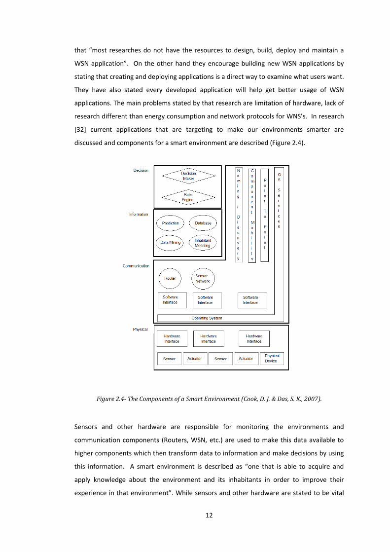
research different than energy consumption and network protocols for WNS’s. In research
[32] current applications that are targeting to make our environments smarter are
discussed and components for a smart environment are described (Figure 2.4).
Figure 2.4- The Components of a Smart Environment (Cook, D. J. & Das, S. K., 2007).
Sensors and other hardware are responsible for monitoring the environments and
communication components (Routers, WSN, etc.) are used to make this data available to
higher components which then transform data to information and make decisions by using
this information. A smart environment is described as “one that is able to acquire and
apply knowledge about the environment and its inhabitants in order to improve their
experience in that environment”. While sensors and other hardware are stated to be vital

13
to monitor the environment to build a fully automated system, a decision-making
component is suggested to be built upon these layers as shown in Figure 2.4.
While the previous research suggests components and architectures for such applications
there is also some research which implements WSN or event-based systems in a specific
area. Research [33] presents a smart home application specifically designed for elderly care.
They state that they use both WSN and RFID’s to be able to track and identify caregivers
inside the house. The experiments are done in a controlled lab environment and apart form
caregiver identification, automated lighting and playing personalized music is also
implemented in the application. They state that their approach is light-weight and stay
invisible while supplying necessary information. In the study [34] a remote surveillance and
monitoring application is detailed. WSN technology is used to enhance the detection
capabilities and improve alarm functionalities. The research attempts to track changes and
also give automated real-time alarms to the end users. A four tiered architecture is used
where the first tier is the sensor nodes which are responsible to track environment. The
second tier is the gateway tier and it forwards the information to upper layers. Another
responsibility of this tier is to use Video Surveillance System to get the visuals where
something is detected by the sensors. The third tier is the management tier where users
can define alarms and controls the system. The last tier is the alarming and display
subsystem. Simulation and real life implementation are both evaluated in that research.
Study [35] also uses a WSN for surveillance but mainly focuses on energy efficiency. They
state that this application requires some important points to be taken into account. First
one is Longevity, the system shall last for at least a few days. Stealth is the second
requirement because it’s crucial for military surveillance. They also declare that the system
shall have an adjustable sensitivity and effectiveness in terms of latency and precision. With
their WSN routing and event dissemination algorithms they claim that their system is
adaptable and achieves an improvement in network lifetime. A WSN system that is
monitoring the seabirds is described in [36]. Temperature, humidity and PIR sensors are
used in burrows of the birds and the gathered data are transferred to a central system with
the help of sensor nodes and gateways. To improve the quality of data and reliability, the
centralized software is improved; also RFID nodes are integrated into a WSN system. A
healthcare system using WSN’s is described in study [37]. Medical sensor nodes are
collecting data such as blood pressure, body temperature, blood sugar levels of patients.
The gathered data are then sent to a sink node which is a web server. The doctors are able
to track patients remotely with the proposed system. Different than the previously

14
discussed studies, research [38] is used in a bigger area aiming to prepare a city wide WSN
testbed. Their research describes the ongoing implementation that monitors wind-speed,
direction, relative humidity, temperature and pressure. The sensor nodes are fixed to street
lights which supply power to the nodes, the nodes communicate with Wi-Fi protocols and
use current security solutions developed for Wi-Fi. They have stated that with this testbed
they support innovation for WSN applications. On the other hand, research [39] states the
difficulties to establish an infrastructure for smart cities. Large number of sensor and
mobile devices and their heterogeneity are stated as two important factors that should be
taken into account during the design. The city is said to have simple, complex, temporal and
other types of context sensitive events together which it brings the need for event
composition and management services. They have pointed out that event-based
computing plays a centralized role in the realization of these applications.

15
CHAPTER 3
COMPLEX EVENT PROCESSING
FRAMEWORK
In this study, we construct a framework to extract high level information in order to get
smart environments. This framework works with wireless sensors and other data sources; it
also utilizes complex event processing for information extraction. The software
components of our proposed framework support event driven architecture and we choose
to use a messaging system which lets the fusion of events in a structural but simple way.
The most important part of our system, the reasoning component is selected as a rule
based system that also allows Complex Event Processing of the events. This module is
capable of processing events with time dimension that lets us define more complex event
rules for our system.
The event driven system we aim to develop is meant to work in a wireless sensor
environment. The hardware components of our system are selected from a wide range of
electronics prototyping platforms. We want our nodes to be programmable and support
different kinds of communication interfaces. To make our system more generic we choose
our boards to be compatible with different types of sensors and be assembled as desired.
This chapter discusses the hardware and software design of the system we develop. In 3.1
an overview of the framework we construct is given while in 3.2 details about the software
components of the event driven system are explained. Section 3.3 clarifies the design of
selected hardware; sensor boards, sensors and communication interfaces.

16
3.1 Framework Overview
We aim to construct a complete framework to be able to extract high level information in a
pervasive computing environment. In such an environment there are numerous data
sources providing raw data; event processing paradigm deals with this data and tries to
make meaningful extractions. Complex Event Processing technology takes this approach
one step further and helps with extracting high level information. Our goal is to construct a
framework that will help gather data from sensors and other data sources and process this
data to be able to provide meaningful information for higher level applications. We want
our framework to be able to get data from both existing and also newly deployed data
sources. We believe currently easily accessible hardware and software can be used to
construct such a framework. This helps the deployment of the framework to be easy and at
the same time inexpensive. Also, with the help of available Complex Event Processing
software we aim to extract higher level information by using the available environmental
data.
The framework we present is used in a classroom environment where we have setup a set
of wireless sensors and an RFID reader. We first implement a prototype and we use a
classroom in our institute in order to test it in a real life environment; we carry out our
experiments when there is an ongoing class inside the classroom. Our goal is to present the
feasibility of our approach and for this we use sensor nodes that are available within our
institute. The prototyping and the real life application details will be discussed in Chapter 4.
3.1.1 Conceptual Design
Figure 3.1 gives a summary of our conceptual design. In this study we aim to gather simple
events from heterogeneous sources and by using a rule engine we extract high level
information. We use Wireless Sensors, RFID data and also supplementary data from a
database. In our framework, incorporating additional data sources as event producers is
always possible. The raw data provided by sensors are converted to simple events, these
and events from other data sources are transferred to a centralized processing unit. We
decide to use a publish/subscribe messaging system to get those simple events to the unit
where our Rule Engine resides. In order to add a new data source to our framework, we
define them as new publishers and change our processing engine to subscribe to their data.
The centralized processing unit is a rule engine that supports complex event processing.
With predefined rules that utilize temporal constraints, aggregation, sequencing and

17
filtering, we try to extract higher level information from the cloud of events produced. We
do not run queries over the events that happen; instead we define our queries beforehand
and let our system make detections whenever new events match the patterns. The main
component containing Event Producers, Messaging Service and Processing Engine in Figure
3.1 refers to our framework that converts raw data to simple events, simple events to
information and finally by Complex Event Processing into high level information.
Figure3. 1 – Conceptual Design
For this study we create a web page to demonstrate our high level information to end
users, for other scenarios it’s possible for other frameworks to subscribe to both high level
information and simple sensor events. Various other applications can use our framework
to get meaningful information from a pervasive environment without dealing with the low
level information present.
3.1.2 Complex Event Processing
Event processing is the most important part of our system because in this research we aim
to make our environments smarter by using a network of sensors and making meaningful
deductions with the use of complex event processing. This module subscribes to the topics
created by event generators and thus retrieves the messages as soon as they are produced.
The retrieved events are used by the reasoning engine to create knowledge from
information. This engine supports complex event processing with the help of temporal
reasoning and also sliding windows.

18
The Event Processing Technical Society (EPTS) has published a glossary to provide a
common language for event processing community [40]. The definitions given in this
glossary are presented below to clarify the difference between normal and complex events:
Event ‘Anything that happens, or is contemplated as happening.’
Complex event
‘An event that is an abstraction of other events called its members.’
Complex event processing (CEP) ‘Computing that performs operations on complex events, including reading, creating, transforming, or abstracting them.’
This means that complex events are produced from the events that have already occurred.
A sensor reading is also a simple event and when all sensor events are gathered, a cloud of
events will be formed with each one having different timestamps. Complex Event
Processing is inspecting the cloud of events and deducing a new event composed of the
other events. With temporal reasoning, absence of events and other parameters, the
events that cannot be formed with simple sensing capabilities are derived by complex event
processing.
Figure 3.2 – CEP Engine Modules
Since CEP needs an inference engine to drive answers from the knowledge base, in this
study we use a rule-based engine for reasoning over events. This component is formed by
a rule base where all extraction rules are stored, an inference engine to run these rules and
a working memory to reason over the event cloud (Figure 3.2). CEP system uses event
matching, event abstraction, temporal-spatial reasoning and detecting relationships for
deriving complex events from simple events.

19
3.2. Software Components
We aim to implement a complex event processing framework to be able to gather
meaningful results from different sensor events and we utilize Event Driven Architecture
(EDA) to achieve this goal. Sensor readings are our events that will drive our system and
CEP component will make reasoning over these measurements. A conceptual model is
proposed in [41] and it offers three different components of EDA; event producers-
consumers, event channel and event processing agent. In this study an event producer
component, an event processing engine and the messaging channel between these
components are designed to work seamlessly with each other. Event generator layer is
formed by microcontrollers that convert raw sensor data into simple events and the
component that transmits the events. To make our messaging more flexible we implement
a publish-subscribe system as our Event Channel. The messaging system is used to make
communication between two components of the system loosely coupled. Finally we
implement a CEP system to reason over the sensor readings. We have chosen a rule engine
with temporal reasoning to form CEP rules. While data from the servers can be converted
to information by simple logical converters, CEP helps to convert information into
knowledge. This module gets sensor messages by the event channel and also publishes
results back again to the event channel. The published Complex Events are presented by a
simple webpage at the application layer.
Figure3. 3 – EDA System Diagram
The details of the components shown in Figure 3.3 are briefly explained in the next
subsections.

20
3.2.1. Event Sources
The sensor nodes used in this study are described in 3.3.1 and they are the main event
generators for our system. Since the microcontrollers let us format and send the output
messages according to our needs, we have sensor type, sensor ID and measurement
combined and sent as one string. This lets us to be able to identify which sensor sends the
data to our sink and what the last reading of that sensor is. The string message starts with
the type of the sensor denoted as a character, continues with the ID of the sensor and
finally following a colon it provides the measurement. There is a special character at the
end to specify the end of the message. Table 3.1 shows the characters used as sensor types.
Example messages then become:
L0:762/r meaning, light sensor whose ID is 0 lastly measured 762.
S1:24,6/r meaning , temperature sensor whose ID is 1 lastly measured 24,6.
Table 3.1- Sensor Type Characters Used In Messages
Character Sensor Type
H Hall Effect
I Infrared Proximity
L Light
S Temperature
T RFID
H Optical Detector
E Electret Microphone
M PIR Motion
These messages are the outputs of our event generators and we gather them in one place
with the help of a sink node. The sink node gets the messages through a wireless medium
and sends them to a virtual serial port via USB. In order not to throttle our one sink node

21
we have coded our microcontrollers to only send state changes for hall effect, infrared
proximity, optical detector and motion sensors while temperature, electret microphone
and light sensors are sending the measurements at fixed time periods.
Figure 3.4 Class Diagram for SensorToJMS component
The sink node sends all messages to our local server where we have implemented a simple
serial port reader to gather all messages sent by our WSN nodes. This module gathers the
messages and parses them according to their types and passes this information to our
Event Channel where the messages are disseminated to other components of our system.
Our component called SensorToJMS has four classes, the first one being the SerialListener
class which is responsible for gathering data, second is the main class which acts as a
controller and it also parses incoming messages and third one, JMSMessaging, is for
messaging between components which is described in the next subsection. The final class
DB serves the purpose of recording all messages in a persistent environment.
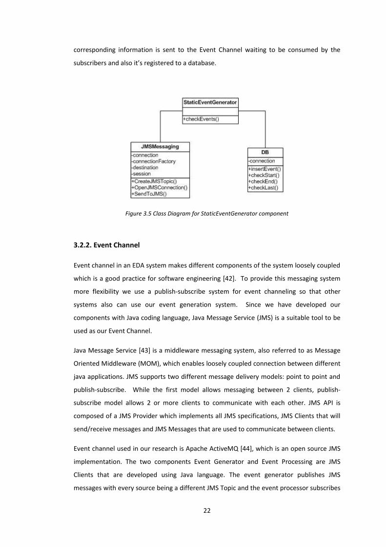
Apart from the sensor producers we have decided to use a static event generator to be able
to understand the timed events planned to occur in the environment where our sensors are
placed. In this study we want to get lecture hours and other simple facts from a given
schedule and send them over the event channel to the event processor. Our
StaticEventGenerator is a simple java program that runs on timed triggers with the help of
Windows Task Manager. The purpose of the program is to check the schedule database if
there is a lecture starting or ending at that time and if it’s the last lecture. The
22
corresponding information is sent to the Event Channel waiting to be consumed by the
subscribers and also it’s registered to a database.
Figure 3.5 Class Diagram for StaticEventGenerator component
3.2.2. Event Channel
Event channel in an EDA system makes different components of the system loosely coupled
which is a good practice for software engineering [42]. To provide this messaging system
more flexibility we use a publish-subscribe system for event channeling so that other
systems also can use our event generation system. Since we have developed our
components with Java coding language, Java Message Service (JMS) is a suitable tool to be
used as our Event Channel.
Java Message Service [43] is a middleware messaging system, also referred to as Message
Oriented Middleware (MOM), which enables loosely coupled connection between different
java applications. JMS supports two different message delivery models: point to point and
publish-subscribe. While the first model allows messaging between 2 clients, publish-
subscribe model allows 2 or more clients to communicate with each other. JMS API is
composed of a JMS Provider which implements all JMS specifications, JMS Clients that will
send/receive messages and JMS Messages that are used to communicate between clients.
Event channel used in our research is Apache ActiveMQ [44], which is an open source JMS
implementation. The two components Event Generator and Event Processing are JMS
Clients that are developed using Java language. The event generator publishes JMS
messages with every source being a different JMS Topic and the event processor subscribes

23
to all these topics to get sensor readings. Finally the outputs of the event processor are also
published to JMS for other components to get meaningful results without subscribing to
sensor topics.
We have arranged our JMS to have different topics for every sensor, this way a system that
wants to get only specific types of sensor readings will only need to subscribe to the topics
of these sensors. When a new reading is published to JMS by event generators, JMS
automatically forwards it to all the subscribers.
For this study we use a remote server for our JMS provider apart from the implementation
where our event generator is running. Both our event generator and event processor has
one class called JMSMessaging to utilize publish-subscribe model in both clients. Also we
have implemented a database to store all the messages published by topics in order to be
able to inspect the messaging history.
3.2.3. Event Processing
This study uses Drools Business Logic Integration Platform [45] which has started as a
business rule management system (BRMS) with a forward chaining inference based rules
engine and then renamed with the addition of more components. In 2009 with version 5,
developers added event processing and workflow capability to their system and after a few
years they renamed their product to turn it to a complete Logic Integration Platform. The
new component implemented for event processing is called Drools Fusion and as described
in their web page it adds some features for event processing while keeping the rule engine
fully active. The new features of Drools Fusion are:
Understand and handle events as first class citizens of the platform
Select a set of interesting events in a cloud or stream of events
Detect the relevant relationships (patterns) among these events
Take appropriate actions based on the patterns detected
The previous versions of the rule engine were only working with facts that are onetime
events that have no time parameters. With Drools Fusion, it’s now possible to define
events with time parameters and the engine will handle them knowing they are events not
facts. Another new feature of Drools Fusion lets the users define events with a timestamp
and duration so that temporal reasoning over events can be made. With all events having a
timestamp and duration, Drools makes it possible to find relationships between events by
24
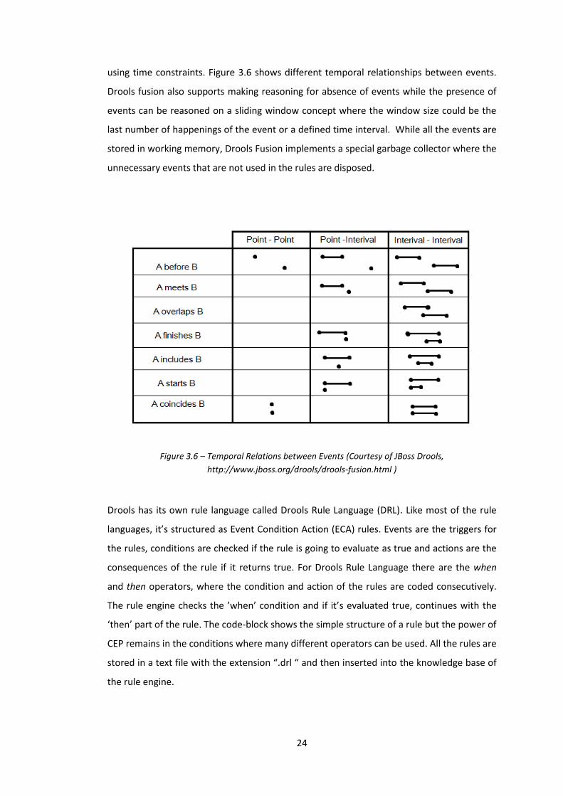
using time constraints. Figure 3.6 shows different temporal relationships between events.
Drools fusion also supports making reasoning for absence of events while the presence of
events can be reasoned on a sliding window concept where the window size could be the
last number of happenings of the event or a defined time interval. While all the events are
stored in working memory, Drools Fusion implements a special garbage collector where the
unnecessary events that are not used in the rules are disposed.
Figure 3.6 – Temporal Relations between Events (Courtesy of JBoss Drools,
http://www.jboss.org/drools/drools-fusion.html )
Drools has its own rule language called Drools Rule Language (DRL). Like most of the rule
languages, it’s structured as Event Condition Action (ECA) rules. Events are the triggers for
the rules, conditions are checked if the rule is going to evaluate as true and actions are the
consequences of the rule if it returns true. For Drools Rule Language there are the when
and then operators, where the condition and action of the rules are coded consecutively.
The rule engine checks the ’when’ condition and if it’s evaluated true, continues with the
‘then’ part of the rule. The code-block shows the simple structure of a rule but the power of
CEP remains in the conditions where many different operators can be used. All the rules are
stored in a text file with the extension “.drl “ and then inserted into the knowledge base of
the rule engine.

25
Simple code-block for Drools Rule Language
For this study, we have implemented the Drools rule engine in a remote computer where
the sensor readings are accessible by subscribing to their topics on JMS. The rules are
written in Drools Rule Language (DRL) and stored in a “.drl” file which is then imported into
the knowledge base for the events to fire them. Whenever an event is inserted,
fireAllRules() function is called for our rule engine to process new events. This function lets
the rules to be checked whenever a new event is inserted into the working memory.
Our third component called JMStoDrools is responsible for subscribing to the topics of the
sensors, creating objects from the messages received and inserting them into the
knowledge base. With the Drools API, the events are reasoned over the rules we have
created and after that the results are published back again to JMS. We have Drools class for
reasoning, JMSMessaging class for publishing and subscribing, and the event classes for
forming the objects that are going to be inserted into the working memory. The rules are
created to be able to derive complex events from simple sensor readings. The next chapter
will briefly describe the system working in a sample environment and how the rules are
structured for such an application.
rule "ruleName"
when
//Conditions
then
//Actions
end

26
Figure 3.7 – Class diagram for JMSToSensor Component
The SensorEvent class is the class that represents the events detected by various sensors in
the classroom while RFIDEvent class is used only for RFID readings. DroolsEvent class is
used to insert the events extracted by the rule engine into the working memory. Finally we
have also created a class called CurrentState to be able to store current static condition of
the classroom in the working memory. Information about instructor, number of students
and lecture times are stored in this class in the working memory. When a state change
occurs we are updating this class inside the working memory and our rule engine is firing
the rules, checking them again according to the changes of the state. Drools class is our
event processing engine where we create our working memory using our rules. This class is
heavily dependent on the Drools API. JMSMessaging class is used to subscribe to the Sensor
and RFID Events and also to publish the deduced events to the JMS. Finally DB class is used
to record Drools Events to a database and also to simulate past values which are recorded
to the database.
3.3. Hardware Components
Recent progress in the technology of WSN has led to different types of WSN hardware to be
produced for both commercial use and research purposes. For our research we want to
use a flexible platform to be able to use different kind of sensors. Furthermore we need a
platform that is easily programmable to have control over the data that should be sent over

27
selected communication interfaces. We decided that the Arduino [46] platform satisfies all
the requirements we needed, thus the sensor boards and sensors are selected to be used
with this platform and coding of sensor boards are carried out using the Arduino language
which is a set of C/C++ functions that can be called within the code.
3.3.1. Design of Sensor Boards
The Arduino platform has different kinds of development boards that work with different
types of applications. For our study we decided that “Arduino Uno” will suit the best
because of its processing ability, output power variety and number of analog and digital
inputs. In our setup, we use two or more sensors on one board thus the need for more
power and more number of inputs was inevitable. Appendix A: Sensor Board Schematic For
Arduino Uno, shows the detailed design of the boards used in this research.
Table 3.2-Summary Information about Arduino Uno
Microcontroller
ATmega328
Operating Voltage 5V
Input Voltage 7-12V
Digital I/O Pins 14 (of which 6 provide PWM output)
Analog Input Pins 6
DC Current per I/O Pin 40 mA
DC Current for 3.3V Pin 50 mA
Flash Memory 32 KB (Atmega328) of which 0.5 KB used by bootloader
SRAM 2 KB (Atmega328)
EEPROM 1 KB (Atmega328)
Clock Speed 16 MHz
This development board basically reads the voltage values from the input pins and converts
them to readable values. These pins are 10 bit analog to digital converters (ADC). For
analog input pins the output of this transfer is a value between 0 and 1023 while the output
values for digital input pins are 0 or 1. These input pins can also be used as output pins that
can provide a maximum of 40 mA, operating at 5V.
32 KB flash memory is sufficient enough to implement a simple measurement reading and
data transferring code block. A simple code block for this type of application can only be a
few KB’s in size. Furthermore Arduino Uno also has support for different libraries that can

28
be used for coding more complex applications on nodes, thus 32KB flash memory can be
used freely without any memory problems.
Arduino Uno boards can work with input voltages from 7 to 12V. We use 7.4V and 9V
batteries for our setup since we want to make our setup completely wireless. The power
for these boards can also be supplied by USB ports or power adapters. For communication
between a computer RX and TX pins on the board are used. The serial communication is
completed by using the USB port as a virtual serial port on the computer.
The following subsections describe the sensors used in this research and define how they
are designed to work with the development boards.
3.3.1.1. Hall Effect Sensor
Hall Effect sensors are used to detect magnetic fields; the output voltage of these sensors
will vary according to the magnetic field around them. The sensor used in this study,
Melexis US1881 [47], is a latching Hall Effect sensor. This makes the sensor to give the
same output until it senses a magnetic field of reverse polarity. The operating voltage of
this sensor is 3.5V to 24V. If the sensor is triggered by a magnetic field it will give same
output voltage as the input voltage while it will only output ground while resting still.
The 3 pins are used for input, ground and output connections. A 10KΩ resistor is used
between input and output pins.
Figure 3.8- Hall Effect Sensor (US1881) Connection on Development Board

29
3.3.1.2. Infrared Proximity Sensor
Proximity sensors are used to sense presence of an object. Infrared (IR) proximity sensor
has one IR receiver and an IR light. It senses the intensity of reflected IR that is sent by its
own IR light. The sensor output changes according to distance of the object reflecting the
IR. Our study uses two different IR proximity Sensors; Sharp GP2Y0A02YK0F [48] for sensing
long range (15cm to 150cm) and Optical Detector QRD1114 [49] to sense nearby objects
(0.5cm to 1 cm). Both sensors work with operating voltage of 5 V. Sharp sensor is
connected with 3 wires as input, ground and output while optical detector is connected
with 4 pin. Two wires used for ground connection and others are input and output pins. As
a pull up resistor a 5.6kΩ resistor is used between input and output connections and a
200kΩ resistance is used for input connection.
Figure 3.9- Infrared Proximity Sensor (Sharp) Connection on Development Board

30
Figure 3.10- Optical Detector (QRD1114) Connection on Development Board
3.3.1.3. Passive Infrared (PIR) Motion Sensor
PIR sensors are used to detect radiated IR measurements from the objects. The sensor
detects the changes around the sensor so it’s commonly used as motion detectors. When
an infrared source with one temperature passes in front of the previously sensed infrared
source with a different temperature the sensor sends a low signal from its output pins. The
sensor used in our study [50] is an open collector, works from 3.3 to 12 volts and needs a
resistor (10kΩ) between its input and output pins. The other pin is connected to ground.

31
Figure 3.11- PIR Motion Sensor (SE-10) Connection on Development Board
3.3.1.4. Photoresistor
Different from the previously discussed sensors, GL5528 [51] is only a resistor whose
resistance changes depending on the amount of light the sensor is exposed to. When the
resistance changes, the amount of voltage passing through changes, as a result ambient
light measurement can be detected. To measure the ambient light, one end is connected to
power and the other to a pull-down resistor to ground. By connecting point between the
fixed pulldown resistor (10kΩ) and the photocell resistor to the analog input the
measurements can be read.

32
Figure 3.12-Photoresistor Connection on Development Board
3.3.1.5. Electret Microphone
An electret microphone is a type of microphone which has an electret material to hold
electrical charge constantly thus removing the need a charge placed on it unlike the
condenser microphone. This sensor [52] has an amplifier to make the sounds convertible by
microcontrollers ADC. It works from 2.7V to 5.5V and 3 pins are connected as input, ground
and output.
Figure 3.13 - Electret Microphone Connection on Development Board
33
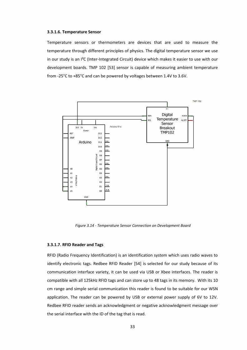
3.3.1.6. Temperature Sensor
Temperature sensors or thermometers are devices that are used to measure the
temperature through different principles of physics. The digital temperature sensor we use
in our study is an I²C (Inter-Integrated Circuit) device which makes it easier to use with our
development boards. TMP 102 [53] sensor is capable of measuring ambient temperature
from -25°C to +85°C and can be powered by voltages between 1.4V to 3.6V.
Figure 3.14 - Temperature Sensor Connection on Development Board
3.3.1.7. RFID Reader and Tags
RFID (Radio Frequency Identification) is an identification system which uses radio waves to
identify electronic tags. Redbee RFID Reader [54] is selected for our study because of its
communication interface variety, it can be used via USB or Xbee interfaces. The reader is
compatible with all 125kHz RFID tags and can store up to 48 tags in its memory. With its 10
cm range and simple serial communication this reader is found to be suitable for our WSN
application. The reader can be powered by USB or external power supply of 6V to 12V.
Redbee RFID reader sends an acknowledgment or negative acknowledgment message over
the serial interface with the ID of the tag that is read.

34
3.3.2. Coding with Sensor Boards
Arduino development environment Arduino 1.0 [55] gives users the opportunity to use
their own code to have control over analog and digital input/outputs. With its C/C++ like
coding language it’s easy to get the measurements from the sensors and send them over a
serial connection. Arduino also has different libraries for more complex programming
scenarios; Ethernet library for web server applications, wire library to communicate with I2C
devices, servo for controlling servo motors, SD library to use SD card on applications and
many other libraries are also available.
Every Arduino code must have 2 main functions to be able to work. First one is the setup()
function where variables are initialized and libraries are included. This function will work
only once after a reset of power of the board. The second one is called the loop() and as the
name suggest this function runs as long as there is power on the board. All sensing and
communication functions must run in this function.
Main code-block for development boards
There are two functions to get readings from the digital and analog pins, DigitalRead() and
AnalogRead(). When the pin number is used as parameters with these functions, the result
of the corresponding pin is returned. With the same principle DigitalWrite() and
AnalogWrite() are used to give outputs. For our study, we only use input functions and
want to increase the reading periods as long as we can in order to obtain a longer battery
life. To give a break on this looping code, a function called delay() is used with desired
milliseconds passed as parameters.
Finally to send these readings to a remote machine, Serial class is used. This class is created
mainly to communicate through serial ports by using RX and TX pins. While begin() function
starts serial communication with the desired baud rate, print() and println() functions sends
void setup() {
//Initialize Variables
//Include Libraries
}
void loop() {
// Read Measurements
// Send Measurements
}

35
the output through serial ports. While the most common communication is done by USB,
we will discuss other communication interfaces in the next subsection.
In our research, we want our nodes to only read measurements and send them via wireless
communication to a remote machine. Thus we abstain from putting logic in these
development microcontrollers. Arduino lets us use all known control structures, but for this
study we only use them for simple operations. We plan that our codes only get the
measurements from the sensors and form a structured message, then send it over a
communication interface. While some of the sensors send readings constantly
(temperature, ambient light) we want others to send messages when a difference in the
measured phenomenon is detected (PIR Motion, Hall Effect). The code-block below is a very
simple example of our codes. The next chapter will explain more about the actual codes in a
real test environment. This code reads an analog input from pin 0 of the board and sends a
message over serial connection by using 9600 baud rate, then waits 2 seconds before
getting the reading again.
Simple code-block example for development boards
Using a software application provided by the Arduino platform, the code can be uploaded
to the microcontroller by selecting the serial port that the board is connected to. This
application also acts as a simple IDE to write and compile the Arduino code.
3.3.3. Communication Interface
The Arduino Uno has the ability to communicate with a computer or other
microcontrollers. As stated in 3.1.1, the communication is done over a serial interface,
void setup() {
int reading = 0;
Serial.begin(9600);
}
void loop() {
reading = AnalogRead(0);
Serial.print(“Sensed Measurement:”);
Serial.println(reading);
delay(2000);
}

36
ATmega328 provides serial communication, which is available on RX and TX pins. To
convert this serial communication to a USB interface an ATmega8U2 converter is used on
the board and USB connection on the computer appears as a virtual com port. This allows
access to the microcontroller using a USB cable.
To form a WSN, the microcontrollers need to communicate with each other over a wireless
medium. Arduino development boards support extendable modules such as Bluetooth,
Ethernet and ZigBee [56] (IEEE 802.15.4) modules. Since our applications do not need long
range communication and also battery usage is important, we have decided IEEE 802.15.4
to be our wireless communication interface. Special modules called Xbee Modules [57] are
available for use with Arduino microcontrollers. This module simply communicates with
the microcontroller via RX and TX pins, packages the messages and then sends them over
the wireless medium.
Figure 3.15 – Microcontroller Network Schema
For our study we use Xbee modules on every microcontroller as well as the RedBee RFID
reader, thus obtain a complete network of sensors communicating on ZigBee. We also use a
sink module that gathers the data over ZigBee and streams it through serial communication
by means of a virtual com port over USB. Our nodes are adjusted to work on 57600 baud

37
rate and they are communicating with the sink node while sink node is broadcasting to the
network. X-CTU [58] software by Digi is used to modify the properties of Xbee modules.

38
CHAPTER 4
PROTOTYPING AND REAL LIFE
APPLICATION
This chapter briefly explains the details of our case study where we have implemented our
sensors and CEP system. The design of the system that is explained in Chapter 3 is used in
this implementation. A classroom environment is selected for this study where daily class
activities take place. With the help of the sensors that are placed in a simple classroom, we
aim to detect complex events occurring throughout the day and help that classroom
become smarter. In addition, we want to automate daily routines; we detect the
automation cases where actions can be taken, although actuation part of the system is not
a part of this study.
In subsection 4.1, the setup for the smart environment is described starting with coding and
implementation and it continues with placement of sensors and microcontrollers.
Subsection 4.2 gives information about the complex events to be deduced and details the
rules used in this context. Finally in subsection 4.3, conclusion of the real life application is
discussed.
4.1. Classroom Environment Setup
The aim of the study requires a simple classroom to be monitored with sensors and simple
events occurring in this classroom should be collected and processed to get complex
events. The microcontrollers that are detailed in Chapter 3 are used to construct this setup
and the sensors are connected to the microcontrollers as detailed in that chapter. The

39
microcontrollers are coded to send the desired messages to the sink node and these
messages are processed to get complex events. We use three remote computers for this
setup. The first one is in the classroom where the sensors are placed and the sink node is
connected to that computer to get the readings from the sensors. The second one is
responsible for reasoning on all the events and facts and publishes the extractions back to
the JMS. For the Event Channel we use ActiveMQ JMS broker which is residing on the third
unit where we are also using mySQL [59] database to track all the JMS messages. We also
develop a webpage with AJAX technology that is also subscribing to the rule engine outputs
in order to represent the current extracted high level information. This web page is served
in the same computer where the event channel is implemented on Apache ActiveMQ. Jetty
[60] web server is used to publish the webpage and to interact with JMS server Active MQ
libraries are used. Table 4.1 shows the system information of all three computers used in
this study. We use Java programming language to code all of our components and
microcontrollers are programmed with their own coding language called Arduino.
Table 4.1- System Information of Computers Used in Implementation
Computer 1
(Event Producer)
Computer 2
(Event Messaging)
Computer 3
(Rule Engine)
Processor Intel Pentium 4 Intel Core I7 Intel Core 2 Duo P8600
Clock Speed 2.0 Ghz 1.73 Ghz 2.4 Ghz
RAM 736 Mb 4 Gb 4 Gb
Operating System Microsoft Windows XP
Microsoft Windows 7 64 bit.
Microsoft Windows 7 32 bit.
Java jre version 1.6.0_26 1.6.0_25 1.6.0_26
Used Software Libraries
RXTXComm.jar mysql-connector-java-5.1.18-bin.jar
mysql-connector-java-5.1.18-bin.jar
Database - mySQL 4.1 mySQL 4.1
Apache ActiveMQ - Version 5.5.0 -
JBoss Drools - - Version 5.3.0

40
4.1.1 Software Setup
To be able to use the framework generically in all environments, it’s intended that no
special setup is required for the components of the system. The main differences between
different scenarios are the rules and the complex events which are described in the next
subsection for the classroom environment.
As explained in Chapter 3, our system has two main software components; SensorToJMS
and JMStoDrools. The sensors are sending messages over Zigbee and the sink node is
gathering them to transmit over serial interface to our first component. SensorToJMS is
responsible to parse the messages and publish them to JMS which is running on a remote
computer. The second component, JMStoDrools, is subscribing to these topics from a
remote computer and inserts the incoming messages to the Event Processing Engine which
is running on another computer.
Figure 4.1 – Messaging between components
Microcontrollers are coded to be able to send messages over the wireless medium. While
the temperature, noise level, ambient light intensity sensors are sending messages over a
time period, the other sensors are only sending the state changes to preserve battery. To
make this available, simple logic is used on microcontrollers. The codes running on
microcontrollers are presented in Appendix B.

41
4.1.2 Hardware Setup
This case study is completed with 8 different types of sensors, one of them being an RFID
reader. We propose to get measurements from the classroom and from the outside of the
building to help us do the predictions. Our aim is to detect:
- State of the door (locked-unlocked, open-closed ),
- People passing through the door,
- People’s ID’s who enter the classroom,
- Ambient temperatures both inside and outside,
- Ambient light intensity both inside and outside,
- Noise level in the classroom,
- Motion in the classroom.
With the help of these simple events and schedule information (facts about lectures) we
aim to deduce complex events by using the framework. The sensors that are described in
Chapter 3 are used to detect these simple events and these sensors are placed on the
microcontrollers in 4 different locations of the classroom (Figure 4.2). Table 3 shows details
about the usage of sensors for event detection. The following subsections tell about the
placement of sensors and microcontrollers. We have selected door, one wall and outside as
our microcontroller placeholders and those microcontrollers have multiple sensors on
them. To detect the ambient light inside the classroom at two different locations we use
two photoresistors. Likewise we need two different PIR Motion sensors to be used in our
setup to be able to cover a larger area.

42
Table 4.2- Sensor Usage Details
Event Detected Sensor Used
Door state- Open/Closed Hall Effect Sensor and Magnets on door.
Door state- Locked/Unlocked Optical Detector inside the lock to sense door
lock.
People passing through the door Infrared proximity sensor in door threshold
People ID’s RFID Reader
Ambient Temperature Temperature Sensor inside and outside of the
room
Ambient Light Intensity Photoresistor inside and outside of the room
Noise level in the classroom Electret Microphone inside the classroom
Motion in the classroom PIR Motion sensor in the classroom
Each of the microcontrollers is using an Xbee ZigBee radio to communicate wirelessly with
the sink node. Sink node is a convertor which gets the messages from ZigBee and sends
them over a serial interface to the event collector unit. Our first component called
SensortoJMS is residing on this computer.
Figure 4.2 – Microcontrollers Schematic
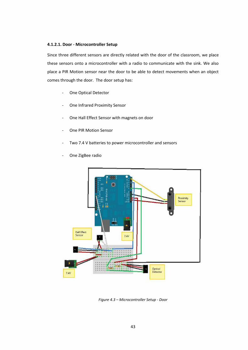
43
4.1.2.1. Door - Microcontroller Setup
Since three different sensors are directly related with the door of the classroom, we place
these sensors onto a microcontroller with a radio to communicate with the sink. We also
place a PIR Motion sensor near the door to be able to detect movements when an object
comes through the door. The door setup has:
- One Optical Detector
- One Infrared Proximity Sensor
- One Hall Effect Sensor with magnets on door
- One PIR Motion Sensor
- Two 7.4 V batteries to power microcontroller and sensors
- One ZigBee radio
Figure 4.3 – Microcontroller Setup - Door

44
4.1.2.2. Outside - Microcontroller Setup
We are interested in the values of temperature and ambient light intensity outside the
classroom so we can deduce events according to these values. The microcontroller is placed
outside and has:
- One temperature sensor
- One photoresistor
- One 4.7V battery to power microcontroller and sensors
- One ZigBee radio
Figure 4.4 – Microcontroller Setup –Outside
4.1.2.3. Inside, Wall - Microcontroller Setup
Inside the classroom we are interested in temperature, ambient light intensity and noise
level values. This setup has:
- One temperature sensor

45
- One photoresistor
- One Electret Microphone
- One 4.7V battery to power microcontroller and sensors
- One ZigBee radio
Figure 4.5 – Microcontroller Setup –Inside, Wall
4.1.2.4. Inside, Wall 2- Microcontroller Setup
Since we want to measure two different light values inside the classroom and also want to
increase the coverage area of motion detection, we place two sensors on the same wall of
the classroom. The setup has:
- One photoresistor
- One PIR Motion Sensor
- One 4.7V battery to power microcontroller and sensors
- One ZigBee radio

46
Figure 4.6 – Microcontroller Setup –Inside, Ceiling
4.1.2.5 RFID Reader
RedBee RFID reader is placed next to the entrance to get the ID’s of the students and
instructor in the classroom. 10 RFID tags are given to the students to be read when they are
entering or exiting the classroom. This module also communicates over Zigbee. With the
reader module an extra radio modem and 7.4V battery are also placed next to the door.
Figure 4.7 - Redbee RFID Reader

47
4.2. Complex Events and Rules
A classroom is a place where students attend lectures; the main actors for a classroom are
students and instructor. For this study we select a classroom as our application area
because lots of activities are taking place during the day around different actors. At first
glance, attending a class seems as the only activity for a classroom, but in realty there are
hidden actors for the classroom like institute personnel responsible for the security of the
classroom equipment. Students and instructor may be the main actors, but during a day the
classroom is used for different courses, thus making different people the main actors for
the activities.
For this study we want to deduce complex events in the classroom with the help of the
sensors that are placed in the classroom. A daily routine for a classroom is:
1. Institute personnel unlock the door for the classroom in the morning
2. Students enter the classroom for the lecture
3. Instructor enters the classroom and starts the lecture
4. A break may be given during the lecture
5. Lecture ends, instructor and students leave the classroom
6. If there are more lectures the routine repeats steps 2 to 5
7. If there are no more lectures, personnel check the classroom and lock the doors
This routine is the main scenario but there may be different actions in a lecture day. The
lecture may start later than normal, the lecture may be extended or cancelled. The
personnel may forget opening the door or locking them when the day ends. With our
complex event detection, we want to make smart decisions and extract high level
information with the help of our rule engine.
As a second objective to practice pervasive computing, we want to make automated
decisions for simple activities in a classroom. Automated light and curtain control to
provide necessary lighting is an example for this. For this study we have decided that our
rules shall be grouped for 3 different time periods: start of the lecture, during the lecture
and end of the lecture. Table 4.3 shows the decisions the rule engine shall make.
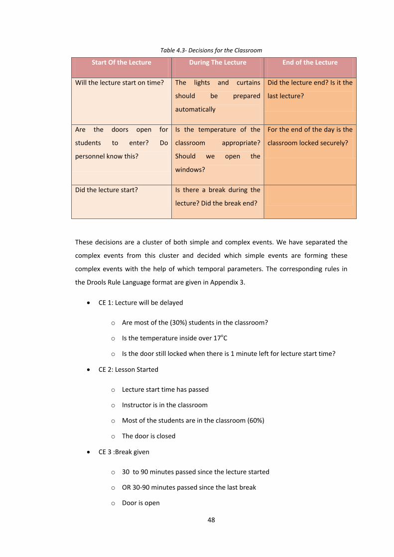
48
Table 4.3- Decisions for the Classroom
Start Of the Lecture During The Lecture End of the Lecture
Will the lecture start on time? The lights and curtains
should be prepared
automatically
Did the lecture end? Is it the
last lecture?
Are the doors open for
students to enter? Do
personnel know this?
Is the temperature of the
classroom appropriate?
Should we open the
windows?
For the end of the day is the
classroom locked securely?
Did the lecture start? Is there a break during the
lecture? Did the break end?
These decisions are a cluster of both simple and complex events. We have separated the
complex events from this cluster and decided which simple events are forming these
complex events with the help of which temporal parameters. The corresponding rules in
the Drools Rule Language format are given in Appendix 3.
CE 1: Lecture will be delayed
o Are most of the (30%) students in the classroom?
o Is the temperature inside over 17oC
o Is the door still locked when there is 1 minute left for lecture start time?
CE 2: Lesson Started
o Lecture start time has passed
o Instructor is in the classroom
o Most of the students are in the classroom (60%)
o The door is closed
CE 3 :Break given
o 30 to 90 minutes passed since the lecture started
o OR 30-90 minutes passed since the last break
o Door is open

49
o People passing through the door
CE 4: Break ended
o 5 to 30 minutes passed since the break
o Door is closed
CE5: Lecture Ended
o Less than 15 minutes remain for the lecture end or end time is passed
o Door is open
o People passing through the door
o Instructor leaves the classroom
o Most of the students leave the classroom (less than 30% remain)
CE6: Lecture finished early
o Door is open
o People passing through the door
o More than 15 minutes remain before lecture finish time
o Instructor leaves the classroom
o Most of the students leave the classroom (less than 30% remain)
CE7: Day ended
o CE 5 OR CE6 is deduced
o Current lecture was the last one in the schedule
o There is no movement inside the room
o Noise level is low
CE8: Classroom Check
o CE7 is deduced
o The door is locked
o The noise level is low after the door is locked.
o There is no motion in classroom after the door is locked.
o The light intensity is low in classroom.
CE9: Day started
o CE7 is deduced
o CE2 is deduced

50
There are also automation rules we also define as complex events
AR1: Open the curtains
o Photoresistor values are low in the classroom
o Photoresistor values are high outside
AR2 :Open the lights
o Photoresistor values are low in the classroom
o Photoresistor values are low outside
AR3 : Open the window
o Temperature values are high in the classroom
o Temperature values are low outside
o Temperature values are above 19oC outside
AR4 : Run air conditioner
o Temperature values are high in the classroom
o Temperature values are high outside
AR5 : Run heater
o Temperature values are low in the classroom
o Temperature values are low outside
These complex events and automation rules are derived and fired by the system we have
implemented in this study. The results of our research are given in the next subsection.
4.3 Results and Discussion
A prototype of the designed system is completed to observe the shortcomings of the
system in a controlled environment. After making the necessary changes, a real life
application is developed in a classroom environment and the outcomes are observed. The
next subsections detail the experience we gained during prototyping and real life
application.
4.3.1. Prototyping
A test setup is first implemented in the “Wireless Lab” of Informatics Institute to see the
results of the implemented system on a prototype. Hardware components of the system

51
are prepared as sensor nodes and they are placed on the door, ceiling and wall of the
laboratory. The final set is placed outside the window to get the measurements of outside
temperature and ambient light intensity. (Figure 4.8 and Figure 4.9)
Figure 4.8- Prototype Implementation In Wireless Lab-Ceiling
During the hardware implementation, we have seen that power requirements for the
sensors may be overwhelming for the microcontrollers. The door setup has 4 different
sensors and two of them (PIR and Hall Effect) need to be powered externally to operate
robustly. We have also examined that low capacity batteries run out quickly when the
quantity of messages sent by one microcontroller is large in amount. This led us to use
some precautions; we have used 7.4V 1000mA batteries on microcontrollers and added
extra batteries to power the sensors when needed. As the processing power consumption
is lower than transmitting power consumption we have decided to use some control
structures to reduce the message sending frequency of the microcontrollers. The basic
design for this was to send the messages when a state change is detected. Opening a door,
motion detection, door unlocked are examples of this messages and the messages are only
sent once by the microcontroller. The photoresistor and temperature sensors are
measuring constantly changing phenomena but these measurements are not time critical
measurements so we have decided to use a time period to delay the message sending. For
this prototype sixty seconds was the delay time before another measurement is sent over
the wireless medium.

52
Figure 4.9- Prototype Implementation on the Wireless Lab-Door
This decision was important because we didn’t want to use any processing on the sensor
nodes. For this study our aim is to keep whole logic of the system at one point. When we
look at the system components, we can see that apart from Event Processing Engine other
components do not contain any logic. We use this design to be able to easily maintain the
processing module when needed. Thus the coding of the microcontrollers is carefully
adjusted that no logical reasoning is done over the measurements. The codes only detect
the measurements and send them when there is a state change. As described in Chapter 3
the microcontrollers’ output is either 1-0 or a value changing between 0-1023. Sensor
nodes are not aware of the meaning of the value they measure. The only exception for this
structure was the special I2C temperature sensor which changes the value to a decimal

53
showing the ambient temperature as Celsius degree. Even for this exception,
microcontroller is not aware that this value represents a meaningful measurement.
Another reason to decrease the volume of messages sent by the microcontrollers was the
reading capacity of our sink node. Buffer size for a serial connection is limited, thus high
volume of events should be taken into account. Since we are using a special character for
the end of the messages, getting wrong measurements is not possible for our system but
missing data may end up with defective reasoning in the real environment. There are two
possible solutions for this problem. First one is omitting missing data and reasoning over
the arrived data coming from the same sensor. Event processing engine may decide state
changes by inspecting all the messages coming from the sensors. Second solution is
reducing messages to send messages without any conflict by sending state changes only.
We apply the second solution which is more suitable because it is also a better practice for
power preservation.
The event processing component of our system is designed to work with the inputs of
events without any user interaction. Drools rule engine lets the users control when to fire
the rules and also makes it possible to run the processing engine in a loop until user decides
to stop it. For this research we have decided that rule engine should fire the rules whenever
a new event is added to the system. Since we are already using a messaging system, we are
aware of the incoming sensor events, thus running the rules at receiving time is a proper
solution. The complex events can be detected by any of the input coming from the sensors
so this way we are sure that none of the events are missed by the rule engine. This is the
right way to implement an event driven system because the system is reasoning over the
incoming events without any user input or by predefined actions.
4.3.2. Real Life Application
After we have successfully completed our prototyping in the laboratory, a real set-up is
established in a classroom in the Informatics Institute. (Figure 4.10 and Figure 4.11) The
four microcontroller setup and the RFID reader described in Chapter 3 are implemented in
the classroom where real lectures are given. The SensorToJMS component is resting on a
computer in the classroom which has the sink node attached. The gathered measurements
are then distributed to the ActiveMQ JMS server over the Local Area Network (LAN). The
remote computer running the JMS server lets our JMStoDrools component to subscribe to
the events and the reasoning is completed in the computer where this component is

54
residing. The outcome of our CEP engine is then shown on a webpage as an example of the
application layer (Figure 4.12).
Figure 4.10- Prototype Implementation In Classroom-Wall
Figure 4.11- Prototype Implementation in the Classroom-Door
We have run our system during a day where one lesson is taking place in the classroom we
have implemented our framework. The start and end of the day are thus only connected to
that one lesson. Some assumptions are needed to be able to detect complex events

55
happening in the classroom. These assumptions are implemented in the rules mainly as
temporal and also as other conditions. For a simple lesson we assume:
- It will last for 3 hours
- The first break could be given after 30-90 minutes of lecture start
- 30% of the students are needed for lecture start
- Lectures could start at 40th minute of the hour and end at 30th minute of the
hour.
- A break should as long as 5 to 30 minutes
- A normal lecture ending should happen if there is less than 15 minutes remaining
to the end time of the lecture.
The engine is running constantly and we can’t have any restriction over the frequency of
the events incoming in a real environment. We have observed that during the reasoning
there is not high amount of processer usage. Still we use a dedicated computer to operate
as the Event Processing part of our system. Also as we can’t be sure about the amount of
events in the cloud at a given moment, we need a high memory in our system. All the
events are inserted into the working memory and this causes memory problems when the
amount of events gets higher. Drools helps to solve this issue by removing the old, non
relative events from the working memory; by checking the rules in the rule base the engine
decides which events are not related with the rules. Also Drools API gives the possibility to
change events in the working memory. Programmer can design the system so that new
events with the same types are not inserted into the knowledgebase again, instead they
can update the parameters of an old event. With changing timestamp, the rules should be
fired again which is done automatically every time when any of the events in the working
memory are changed. This method is not used in our study because the volume of events is
not too much to cope with in our use case.

56
Figure 4.12- Webpage showing the results of event processing
In this real life application we develop a simple web page to show high level information to
end users (Figure 4.12). This web page is subscribed to both high level information and also
to low level data coming from the sensor nodes. This is a simple application that uses our
framework but it shows the availability of our framework for other applications.
Table 4.4- Complex Event Detection Times
14.12.2012 20.12.2012 21.12.2012 28.12.2012 04.01.2012
Real Time CEP
Real Time CEP
Real Time CEP
Real Time CEP
Real Time CEP
Lecture Started 13:52 13:52 13:53 13:53 13:48 13:48 13:48 13:48 13:46 13:46
Break Given 14:47 14:47 14:38 14:38 14:31 14:31 14:39 14:39 15:08 15:08
Break Ended 15:01 15:01 14:51 14:45 14:39 14:39 14:59 14:59 15:20 15:20
Break Given 15:36 15:36 15:45 N/A 15:42 N/A 15:44 15:44 16:10 16:10
Break Ended 15:55 15:55 15:57 N/A 16:03 N/A 16:05 16:05 16:15 N/A
Lecture Ended 16:34 16:35 16:41 16:45 16:38 16:43 16:40 16:40 16:45 16:45
We have completed our study by running our system on five different days and successfully
extracting high level information. Four hours of data collection for each day give us the
results presented in Table 4.4. Only six important complex events are listed in that table
while there are also other CE rules and automation rules. The real occurrence time of the
complex events and the deduction made by our framework is compared. Apart from three
CE all the others are deduced in the same minute; we can say that our framework is able to
extract high level information in the same minute whenever a complex event happens. As

57
seen in the Table 4.4, five of the complex events are not detected due to the reasons
discussed in the next subsection. As there are a total of 30 complex events presented in the
table we have observed that our framework is capable of detecting complex events with
83.3% of success ratio. We have reached our aim of deducing predefined complex events,
thus proved that a simple environment can be turned into a smarter one with the help of
WSN’s and CEP using the currently available software and hardware products. The
limitations and the observations experienced in this implementation are discussed in the
next subchapter.
4.3.3. Discussion
With this study we believe that we are able to use CEP technology on WSN’s to convert
information into knowledge. With current commercial WSN products and Business Rule
Engines, which are mostly used for banking applications or organizational decision making,
we are able to implement a sample system in our institute. This study shows that current
technology can be used to make smart environments which are the main actors for the
future pervasive computing scenarios.
During the study we have encountered some difficulties while extracting our complex
events. The first issue we had to deal with was the volume of the events happening in the
classroom environment. Although we have decided to transmit only the state changes,
some sensors must be active and transmit the events whenever they occur (PIR Motion,
Electret Microphone). This may cause a large amount of transmission according to the
sensed area. Figure 4.13 shows the number of events in the classroom and it’s clearly seen
that when only state changes are sent, volume of events greatly decrease. For our study we
have seen that electret microphone senses a large number of events during a lecture which
causes a lot of transmission and brings forth the problem of missing events. Also these
electret data are not included in the figure because the number of electret microphone
data is 1000 times more than the next highest value. The volume problem will be seen
more frequently when the number of sensors in the environment is increased. The solution
for this shortcoming might be using another sink node to decrease the volume of events on
one sink node or implementing some more logic on the sensors to decrease the volume of
events. We think that adjusting sensors to send state changes and also some reminders
within a fixed interval will be a practical solution for the missing events.

58
Figure 4.13- Number of Events for Five Days of Measurement
Another issue examined was specific to our case because our scenario was heavily
dependent on deduced events. Some complex events were pre-conditions of other
complex events like the “CE 3: Break given”. In order to decide the break given, the lecture
must have been already started. When everything works without any problem this issue
was not seen, but in an uncontrolled environment there may be some difficulties apart
from the shortcomings of the system. In our case, our sensors were removed from their
places, sensor cables were unplugged by accident in the classroom. These issues cause
events not to be extracted if they are dependent on these sensors. And furthermore the
other complex events cannot be deduced either, if the lost complex event is in their pre-
conditions. This study was dependent on the number of sensors and sensor types thus
these problems were to be faced during the implementation. To be more precise and
overcome this issue, we suggest increasing the sensor types and number in the
environment in order to gather more events. By using different types of sensors we can
sense more things within the environment which may help writing alternative rules to
detect the same complex event. For this implementation we think using pressure sensors
under chairs, using a color light sensor for projector, using accelerometers carried by
students are some examples of improving the sensing capability of the system used. Using
more sensors will apparently lead us to the first issue that is discussed so it is essential that
both issues must be solved together.

59
Apart from the shortcomings, we believe that it’s possible to extract high level information
in a classroom by using the methodology of this research. The sensor numbers and types
are limited for this study, but with the events we have gathered from the classroom we
have successfully deduced our Complex Events. We have discussed that with more types
and number of sensors we can improve the precision of our system. However this does not
mean we are not able to extract Complex Events with our system. By definition of the
complex events [40] there must be other events as the member of the Complex Event.
More members in the defined event do not always mean a better extraction of the
Complex Event. In this study we have seen that measuring the noise level in the classroom
was not beneficial for our Complex Events. Figure 4.14 presents the noise level
measurements in the classroom on 28.12.2011. Before we started our implementation, we
predicted that noise level would increase during break times and decrease when lecture
started. In our institute we have seen that during the break times, the classroom noise
level does not change significantly, thus making our sensor irrelevant for our Complex
Event. By looking at the figure we can say that noise level has both high and low peeks
during the lecture, even when there is no break. Because of this irrelevancy, Electret
Microphone sensor prevents us to match the defined event while we can detect them at
the right time without the usage of this sensor. We believe that while deciding the
members of the complex event, relevant events must be carefully inspected and without
complicating the rules the right events must be added as members of the event. More
events may be used as alternative rules to deduce the same event or to increase precision
of the Complex Event.
Figure 4.14- Noise Level Measurement in the Classroom

60
CHAPTER 5
CONCLUSION
This chapter summarizes the study and highlights findings and limitations. It also details
the topics which are left out of the scope of this study for future studies.
5.1 Summary of Study
Our aim in this study is to extract high level information using simple readings from the
sensors. The rules given in Chapter 4 are implemented using DRL and by inserting the
incoming events (sensor readings for our case) to the knowledgebase, where the rules are
defined, rules are fired. Without manual input, we let the sensors detect the state changes
in the environment, as a result we have an event driven system which is capable of making
smart deductions. With our simple sensors and complex event processing technique, we
have achieved our goal of making an environment smarter as described in [32]. This result
shows us that by using currently available technology, a simple environment can become
smarter. Study [31] explains limitation of hardware as a main issue in pervasive computing
applications; by using available and inexpensive hardware we claim that it’s possible to
construct a smart environment. Figure 5.1 shows approximate values of our hardware costs
for the real life implementation. We also present that our approach is feasible to be used
with any hardware as data sources with help of our publish/subscribe system. In addition,
we have utilized readily available open source software.

61
RFID Reader and Tags
Sensors Development Boards
Communication Modules
Batteries Total
$90 $55 $240 $125 $50 $560
Figure 5.1- Hardware Cost of the Framework
An event-based system with sensors being the event generators is designed and the event
processing module of the system is supported by a Complex Event Processing engine. Event
generators and event processing engine is loosely coupled with help of an event
messenger. The event processing engine is subscribed to the sensors who are publishing
the detected events. While study [27] is also using a CEP engine to reason over WSN data,
we use a rule based complex event processing engine to correlate the relationships among
simple events by using temporal constraints on the rules. The same rule engine is also used
in [28] for a medical sensor network. Our designed system is then implemented as a
prototype to extract high level information in a classroom environment. Like the
architecture defined in [10] our system takes atomic events and by using our CEP engine
turns them into business events. Our sensors are Event Originators, while Event Modeler
and Event Processing Medium correspond to to our CEP engine component. After
successfully completing prototyping, a real life implementation is deployed in a classroom
in order to detect Complex Events occurring in that classroom. By looking at the challenges
of large area deployments ([38],[39]) we have decided to use a more controlled area in our
real life implementation. Eight different types of sensors are placed at four different
locations of the classroom to gather simple events. We have also used RFID tags in order to
obtain a heterogenic system described as a requirement in [22]. With predefined rules the
gathered events are used to deduce Complex Events by using the system implemented.
After five different experiments, the system is found to be successful to be able to detect
the Complex Events within the same minute of real happening time. The result are
obtained with 83,3% success rate.
During the prototyping process, we have seen that the high frequency and high volume of
the events may throttle the sink node leading to loss of the events. We have chosen our
system to be a centralized one unlike [15], [16]. It’s stated in [18] that in a centralized
system the event processing is not dependent on the frequency events and also distributed
processing needs more power and system requirements on the sensor nodes. We tried to
reduce the volume of the events by designing sensors to only send state changes when
applicable. While making those changes we took care not to put any logic on the sensor

62
nodes because the aim of the study was to keep all logic in one place. Another point we
have observed was the power consumption of the sensor nodes. For this study we have
used 4 different sensor nodes with at least 2 sensors attached to them. We have seen some
sensors need more power than the power supplied by the development boards. Adding
more battery capacity to our sensor implementation was seen necessary. Although we
think that decreasing the message volume will decrease the power consumption, using
more sensors consumes power of the development boards more quickly. With this study
we implement a pervasive computing example in the classroom where the system is
running in the background without any input from the users. The event based architecture
is found to be suitable because we want the system to automatically check all the rules
whenever a new event is detected. By using a publish/subscribe event messaging service,
we design our system so that it publishes the events to our subscriber component, the
event processing engine. After making necessary changes on our prototype
implementation we find out that we can detect our Complex Events with the designed
setup.
Study [28] is very similar to our approach; they use a prototype in a hospital environment
where RFID is the main data source. We try our approach with a real life application where
sensor data, RFID and data from other information systems are equally used. We have
completed our real life implementation in a classroom on five different days. We are able
to detect our complex events at the same time when they occur in the classroom. While
CEP is presented as ill-suited in [29], we claim that it is possible to use CEP technology in
pervasive environments to obtain smart environments.
During this implementation, we have seen that volume of events is still a problem even
after we have changed our design after the prototyping phase. Some sensors that are used
in the implementation have to send all events continuously like PIR motion, electret
microphone and proximity sensors. These sensors send events whenever they sense
anything in the classroom. This increases the volume of events and leads to loss of events
detected. The shortcoming of event loses are already stated in [20]. We propose two
solutions for this shortcoming; the first one is putting more logic in the sensor nodes to
make them send both state changes and also reminders about their states in a fixed time
period. While this solution decreases the volume of events, it also helps missing events to
be detected when a reminder is sent. Second solution is to use more sink nodes to be able
to deal with the high volume of events. We also suggest using more sensors in the
classroom, thus this solution will be beneficial even if the first solution is used. Our

63
complex event rules were dependent on each other. That caused the system to lose all its
ability to detect the events if a previous event was not detected. We suggest that by using
more types of sensors, we will be able to write more rules that can detect the same
complex event which can be used as alternatives to other rules. We also believe more
sensor types will help detection of more complex events which are not implemented in this
study. We observed that our complex events were detected successfully with relevant
simple events by using time constraints between simple events. Increasing the number of
sensors will make rules more reliable, but increasing the type of sensors will not affect a
simple rule if they are irrelevant for that complex event.
This study was limited to the sensor types and numbers available to us during the
implementation phase. We designed our system to support more types of sensors but our
sensor selection was limited to the sensors available in the Wireless Lab of METU
Informatics Institute. This limitation is stated as a difficulty in pervasive computing
applications in [31]. We believe that with more types and number of sensors our system
will become more stable and will be able to deduce more Complex Events which are not
implemented in this study. The shortage of sensor types led to high dependency on these
sensors for our study. Removing any of the sensors from our implementation would cause
it to function improperly. During the real life implementation, we use one classroom in the
Informatics Institute. Using the system for all the classrooms will be a better practice in the
pervasive computing domain. We do not use any actuators in our implementation, even
though we have used some actuation rules which only warn about the action to be taken.
Our study uses a simple network of sensors which are communicating with the sink node
wirelessly, although this setup does not have all the characteristics of a Wireless Sensor
Network.
5.2 Future Work
A direction for future studies is to increase the number of sensors and sensor types and to
observe the outcomes including the performance evaluations. The computational
performance of the system would be evaluated according to events in the knowledgebase
and the number of rules that are implemented. Our study shows that with the current
setup, a single computer being the event processor we do not need any significant
processing power. Our CEP engine removes the events in the knowledgebase when they
are not necessary according to their timestamp and the temporal constraints used in the

64
rules. We did not observe any memory problems during this study but with more events
and rules the memory usage needs to be examined.
As another study different Complex Event Processing Engines can be used with the system
implemented in the classroom and the advantages and disadvantages of them can be
expressed. For this study we have chosen a rule based open source complex event
processing engine, but by the end of 2011 more CEP engines became available with
different mechanisms [61].
The development boards used in this study can be arranged to work like a wireless sensor
network by using the newer versions of ZigBee modems that are deployed on boards.
Another future study can use a WSN to examine the event dissemination in the current
setup. The power consumption statistics and results of development board failures on the
network would be observed.
As another venue for future work, different pervasive computing applications can be
implemented on our EDA framework. We believe that by implementing this test bed in the
Institute, we have made this setup available for future studies. Simple sensor events and
also the Complex Events detected by the engine can be used by subscribing to all of them.
Also security of the system should be provided to prevent any attacks to the system and to
be sure proper messages are received by the subscribers.

65
REFERENCES
[1] Weiser, M. (1999). The computer for the 21st century. SIGMOBILE Mob. Comput. Commun. Rev. 3, 3--11. (Doi: http://doi.acm.org/10.1145/329124.329126.) Retrieved from http://doi.acm.org/10.1145/329124.329126.
[2] Weiser, M. (1993). Hot topics-ubiquitous computing. Computer 26 (10), 71 -72. (Doi: 10.1109/2.237456.) [3] Akyildiz, I. F., Su, W., Sankarasubramaniam, Y. & Cayirci, E. (2002). A survey on sensor networks. Communications Magazine, IEEE 40 (8), 102--114. (Doi: 10.1109/MCOM.2002.1024422.) [4] Akyildiz, I. F. & Kasimoglu, I. H. (2004). Wireless sensor and actor networks: research challenges. Ad Hoc Networks 2 (4), 351 - 367. (Doi: 10.1016/j.adhoc.2004.04.003.) Retrieved from http://www.sciencedirect.com/science/article/B7576-4CDWMMM-1/2/8c25ac6ebd5ab2e50ce172498c2add9a. [5] Demirkol, I., Ersoy, C. & Alagoz, F. (2006). MAC protocols for wireless sensor networks: a survey. Communications Magazine, IEEE 44 (4), 115--121. Retrieved from http://ieeexplore.ieee.org/xpls/abs_all.jsp?arnumber=1632658. [6] Intanagonwiwat, C., Govindan, R. & Estrin, D. (2000). Directed Diffusion: A scalable and robust communication paradigm for sensor networks. In MOBICOM (pp. 56--67). ACM. [7] Römer, K., Frank, C., Marrón, P. J. & Becker, C. (2004). Generic role assignment for wireless sensor networks. In Proceedings of the 11th workshop on ACM SIGOPS European workshop. ACM. Retrieved from http://doi.acm.org/10.1145/1133572.1133588. [8] Terfloth, K., Wittenburg, G. & Schiller, J. (2006). FACTS- A Rule-based Middleware Architecture for Wireless Sensor Networks. In Communication System Software and Middleware, 2006. Comsware 2006. First International Conference on (pp. 1 -8). [9] Madden, S. R., Franklin, M. J., Hellerstein, J. M. & Hong, W. (2005). Tinydb: An acquisitional query processing system for sensor networks. ACM Trans. Database Syst 30,

66
2005. [10] Paschke, A. & Vincent, P. (2009). A reference architecture for Event Processing. In Proceedings of the Third ACM International Conference on Distributed Event-Based Systems (pp. 25:1--25:4). ACM. (ISBN: 978-1-60558-665-6.) Retrieved from http://doi.acm.org/10.1145/1619258.1619291. [11] Hinze, A., Sachs, K. & Buchmann, A. (2009). Event-based applications and enabling technologies. In Proceedings of the Third ACM International Conference on Distributed Event-Based Systems (pp. 1:1--1:15). ACM. (ISBN: 978-1-60558-665-6.) Retrieved from http://doi.acm.org/10.1145/1619258.1619260. [12] Wang, F., Liu, S. & Liu, P. (2009). Complex RFID event processing. The VLDB Journal 18, 913--931. (Doi: http://dx.doi.org/10.1007/s00778-009-0139-0.) Retrieved from http://dx.doi.org/10.1007/s00778-009-0139-0. [13] Son, B.-K., Lee, J.-H., Park, K.-L., Kim, C.-G., Kim, H.-C. & Kim, S.-D. (2007). An efficient method to create business level events using complex event processing based on RFID standards. In Proceedings of the 5th IFIP WG 10.2 international conference on Software technologies for embedded and ubiquitous systems (pp. 1--10). Springer-Verlag. (ISBN: 3-540-75663-9, 978-3-540-75663-7.) Retrieved from http://portal.acm.org/citation.cfm?id=1778978.1778980. [14] Wang, W., Sung, J. & Kim, D. (2008). Complex Event Processing in EPC Sensor Network Middleware for Both RFID and WSN. In Object Oriented Real-Time Distributed Computing (ISORC), 2008 11th IEEE International Symposium on (pp. 165 -169). [15] Cugola, G. & Margara, A. (2009). RACED: an adaptive middleware for complex event detection. In Proceedings of the 8th International Workshop on Adaptive and Reflective Middleware (pp. 5:1--5:6). ACM. (ISBN: 978-1-60558-850-6.) Retrieved from http://doi.acm.org/10.1145/1658185.1658190. [16] Pietzuch, P. R., Shand, B. & Bacon, J. (2004). Composite Event Detection as a Generic Middleware Extension. IEEE Network 18 (1), 44-55. Retrieved from http://dblp.uni-trier.de/db/journals/network/network18.html#PietzuchSB04. [17] Fei, Y., Hu, J., Hua, E. & Luo, Z. (2009). RFID Middleware Event Processing Based on CEP. In Proceedings of the 2009 IEEE International Conference on e-Business Engineering (pp. 481--486). IEEE Computer Society. (ISBN: 978-0-7695-3842-6.) Retrieved from http://dx.doi.org/10.1109/ICEBE.2009.76. [18] Terfloth, K., Hahn, K. & Voisard, A. (2007). On the Cost of Shifting Event Processing within Wireless Environments. In M. Chandy, O. Etzion & R. von Ammon (ed.),Event Processing. Internationales Begegnungs- und Forschungszentrum für Informatik (IBFI), Schloss Dagstuhl, Germany. Retrieved from http://drops.dagstuhl.de/opus/volltexte/2007/1141. [19] Abadi, D. J., Madden, S. & Lindner, W. (2005). REED: robust, efficient filtering and event detection in sensor networks. In Proceedings of the 31st international conference on Very large data bases (pp. 769--780). VLDB Endowment. (ISBN: 1-59593-154-6.) Retrieved from http://portal.acm.org/citation.cfm?id=1083592.1083681.

67
[20] Marrón, P. J., Sauter, R., Saukh, O., Gauger, M. & Rothermel, K. (2006). Challenges of Complex Data Processing in Real World Sensor Network Deployments. In: Proceedings of the ACM Workshop on Real-World Wireless Sensor Networks (REALWSN’06 (pp. 43--48). [21] Dziengel, N., Wittenburg, G. & Schiller, J. (2008). Towards Distributed Event Detection in Wireless Sensor Networks. In DCOSS [22] M. Marin-Perianu, N. Meratnia, M. Lijding, and P. Havinga. (2006). Being aware in wireless sensor networks. In 15th IST Mobile and Wireless Communication Summit, Capturing Context and Context Aware Systems and Platforms Workshop, 2006. [23] Wu, B., Liu, Z., George, R. & Shujaee, K. (2005). eWellness: Building a Smart Hospital by Leveraging RFID Networks. In Engineering in Medicine and Biology Society, 2005. IEEE-EMBS 2005. 27th Annual International Conference of the (pp. 3826 -3829). [24] Fei, X. & Magill, E. (2008). Rule Execution and Event Distribution Middleware for PROSEN-WSN. In Sensor Technologies and Applications, 2008. SENSORCOMM '08. Second International Conference on (pp. 580 -585). [25] Manjanatha, S., Bestavros, A., Gaynor, M. & Moulton, S. (2007). A Rule-Based Decision Framework for Medical Sensor Networks. In High Confidence Medical Devices, Software, and Systems and Medical Device Plug-and-Play Interoperability, 2007. HCMDSS-MDPnP. Joint Workshop on (pp. 192 -193). [26]Churcher, G. E. & Foley, J. (2010). Applying Complex Event Processing and Extending Sensor Web Enablement to a Health Care Sensor Network Architecture. In O. Akan, P. Bellavista, J. Cao, F. Dressler, D. Ferrari, M. Gerla, H. Kobayashi, S. Palazzo, S. Sahni, X. (S. Shen, M. Stan, J. Xiaohua, A. Zomaya, G. Coulson, S. Hailes, S. Sicari & G. Roussos (ed.),Sensor Systems and Software, Vol. 24 (pp. 1-10). Springer Berlin Heidelberg. (ISBN: 978-3-642-11528-8.) Retrieved from http://dx.doi.org/10.1007/978-3-642-11528-8_1. [27] Zoumboulakis, M. & Roussos, G. (2007). Escalation: complex event detection in wireless sensor networks. In Proceedings of the 2nd European conference on Smart sensing and context (pp. 270--285). Springer-Verlag. (ISBN: 3-540-75695-7, 978-3-540-75695-8.) Retrieved from http://dl.acm.org/citation.cfm?id=1775377.1775399. [28] Yao, W., Chu, C.-H. & Li, Z. (2011). Leveraging complex event processing for smart hospitals using RFID. J. Netw. Comput. Appl. 34, 799--810. (Doi: http://dx.doi.org/10.1016/j.jnca.2010.04.020.) Retrieved from http://dx.doi.org/10.1016/j.jnca.2010.04.020. [29] Romer, K. & Mattern, F. (2004). Event-based systems for detecting real-world states with sensor networks: a critical analysis. In Intelligent Sensors, Sensor Networks and Information Processing Conference, 2004. Proceedings of the 2004 (pp. 389 - 395). [30] Pinkerton, A. (2006). Pervasive Computing (PostNote). Parliamentary Office of Science and Technology. [31] Lifton,J.&Laibowitz,M. (2005). Application-led Research in Ubiquitous Computing: A Wireless Sensor Network Perspective, UbiApp Workshop, 2005.

68
[32] Cook, D. J. & Das, S. K. (2007). How smart are our environments? An updated look at the state of the art. Pervasive Mob. Comput. 3, 53--73. (Doi: 10.1016/j.pmcj.2006.12.001.) Retrieved from http://portal.acm.org/citation.cfm?id=1225943.1226005. [33] Hussain, S., Schaffner, S. & Moseychuck, D. (2009). Applications of Wireless Sensor Networks and RFID in a Smart Home Environment. In Proceedings of the 2009 Seventh Annual Communication Networks and Services Research Conference (pp. 153--157). IEEE Computer Society. (ISBN: 978-0-7695-3649-1.) Retrieved from http://portal.acm.org/citation.cfm?id=1545008.1545208. [34] Pramod, P., Srikanth, S., Vivek, N., Patil, M. & Sarat, C. (2009). Intelligent Intrusion Detection System (In2DS) using Wireless Sensor Networks. In Networking, Sensing and Control, 2009. ICNSC '09. International Conference on (pp. 587 -591). [35] He, T., Krishnamurthy, S., Stankovic, J. A., Abdelzaher, T., Luo, L., Stoleru, R., Yan, T. & Gu, L. (2004). Energy-Efficient Surveillance System Using Wireless Sensor Networks. In Mobisys (pp. 270--283). ACM Press. [36] Naumowicz, T., Freeman, R., Heil, A., Calsyn, M., Hellmich, E., Brдndle, A., Guilford, T. & Schiller, J. (2008). Autonomous monitoring of vulnerable habitats using a wireless sensor network. In Proceedings of the workshop on Real-world wireless sensor networks (pp. 51--55). [37] Zhang, P. & Chen, M. (2008). A remote health care system based on wireless sensor networks. In Computer Supported Cooperative Work in Design, 2008. CSCWD 2008. 12th International Conference on (pp. 1102 -1106). [38] Murty, R., Mainland, G., Rose, I., Chowdhury, A., Gosain, A., Bers, J. & Welsh, M. (2008). CitySense: An Urban-Scale Wireless Sensor Network and Testbed. In Technologies for Homeland Security, 2008 IEEE Conference on (pp. 583 -588). [39] Buchmann, A. P. (2007). Infrastructure for Smart Cities: The Killer Application for Event-Based Computing. In Dagstuhl Seminars [40] Luckham, D. & Schulte, R. (2008). Event Processing Glossary - Version 1.1 (Glossary ). epts - Event Processing Technical Society. Retrieved from http://www.ep-ts.com/component/option,com_docman/task,doc_download/gid,66/Itemid,84/. [41] Edwards, M. (2010). A Conceptual Model for Event Processing Systems. Nanoscale 3 (5), 1--47. Retrieved from http://www.ncbi.nlm.nih.gov/pubmed/21547279. [42] Brenda M. Michelson. (2006). Event-Driven Architecture Overview: Event-Driven SOA Is Just Part of the EDA Story. Patricia Seybold Group / Business-Driven Architecture SM, Retrieved from: http://www.omg.org/soa/Uploaded%20Docs/EDA/bda2-2-06cc.pdf [43] JMS – Available at: http://www.oracle.com/technetwork/java/index-jsp-142945.html (Accessed: 24 August 2011) [44] Apache ActiveMQ– Available at: http://activemq.apache.org/ (Accessed: 22 September 2011)

69
[45] JBoss-Drools The Business Logic Integration Platform – Available at. http://www.jboss.org/drools (Accessed: 30 August 2011) [46] Arduino – Available at: http://www.arduino.cc (Accessed: 24 August 2011) [47] Melexis US1881 - Available at: http://www.melexis.com/Hall-Effect-Sensor-ICs/Hall-Effect-Latches/US1881-140.aspx (Accessed: 15 December 2011) [48] Sharp GP2Y0A02YK0F - Available at: http://www.sharpsma.com/webfm_send/1487 (Accessed: 15 December 2011) [49] QRD114 Reflective Object Sensor - Available at: http://www.fairchildsemi.com/pf/QR/QRD1114.html (Accessed: 15 December 2011) [50] Passive Infrared (PIR) Detector SE-10- Available at: http://www.pololu.com/catalog/product/1635 (Accessed: 15 December 2011) [51] Photocell GL5528 - Available at: http://us.100y.com.tw/ChanPin.asp?MNo=53901 (Accessed: 15 December 2011) [52] MD9745APZ-F Electret Microphone- Available at: http://www.knowles.com/search/prods_pdf/MD9745APZ-F.pdf (Accessed: 15 December 2011) [53] TMP 102 Temperature Sensor – Available at: http://www.ti.com/product/tmp102 (Accessed: 15 December 2011) [54] RedBee RFID Reader – Available at: http://www.roboticsconnection.com/p-99-redbee-rfid-reader-v11.aspx (Accessed: 15 December 2011) [55] Arduino 1.0 – Available at: http://www.arduino.cc/en/Main/Software (Accessed: 24 August 2011) [56] ZigBee Alliance –Available at: http://www.zigbee.org/ (Accessed: 29 August 2011) [57] Digi - XBee-PRO® 802.15.4 OEM RF Modules – Available at: http://www.digi.com/products/wireless-wired-embedded-solutions/zigbee-rf-modules/point-multipoint-rfmodules/xbee-series1-module#overview (Accessed: 29 August 2011) [58] Digi -Product: XCTU - Available at: http://www.digi.com/support/productdetl.jsp?pid=3352&osvid=0&s=316&tp=5&tp2=0 (Accessed: 29 August 2011) [59] MySQL Community Server– Available at: http://www.mysql.com/downloads/mysql/ (Accessed: 22 September 2011) [60] JETTY– Available at: http://www.eclipse.org/jetty/ (Accessed: 22 September 2011) [61] The CEP Market at the end of 2011– Available at: http://tibcoblogs.com/cep/2011/12/06/the-cep-market-at-the-end-of-2011/ (Accessed: 25 December 2011)

70
APPENDICES
Appendix A : Sensor Board Schematic For Arduino Uno

71
Appendix B : Microcontroller Codes
Microcontroller Code -Door
/* Uno 5
/* Halleffect,proximity,pressure sensors
/* Used at clasroom door
/* M.Ozge Kaya; Informatics Institute,METU
*/
int hallEffectPin = 8;
int proximityPin = A5;
int opticalPin =A0;
int proximityThreshold = 200;
int proximityReading = 0;
int hallReading = 0;
int hallSwitch=0;
int optical =0;
int lockCounter = 0;
int unlockCounter = 0;
int lockSwitch =3;
int timer = 500;
int alarmPin = A3;
int alarmValue = 0;
long previousMillis = 0;
long interval = 2000;
void setup(){
Serial.begin(57600);
pinMode(buzzerPin, OUTPUT);
pinMode(alarmPin, INPUT);
delay (3000);
}
void loop(){
optical = analogRead(opticalPin);
hallReading = digitalRead(hallEffectPin);
proximityReading = analogRead(proximityPin);
//just to slow down the output - remove if trying to catch
an object passing by
delay(180);
// Selected Readings
if (proximityReading >= proximityThreshold) {
/*If lenght changes(An object passing) ,
/*I0: Infrared at door.
/*Send value 1 meaning there is movement.*/
Serial.print("I0:1");
Serial.print("\r");
}
/* Detect if door is open or closed
/* H0: HallEffect at door.
/* Send 1 for open,send 0 for closed
/* HallSwitch is used for sending open and close messages fo
r once
*/
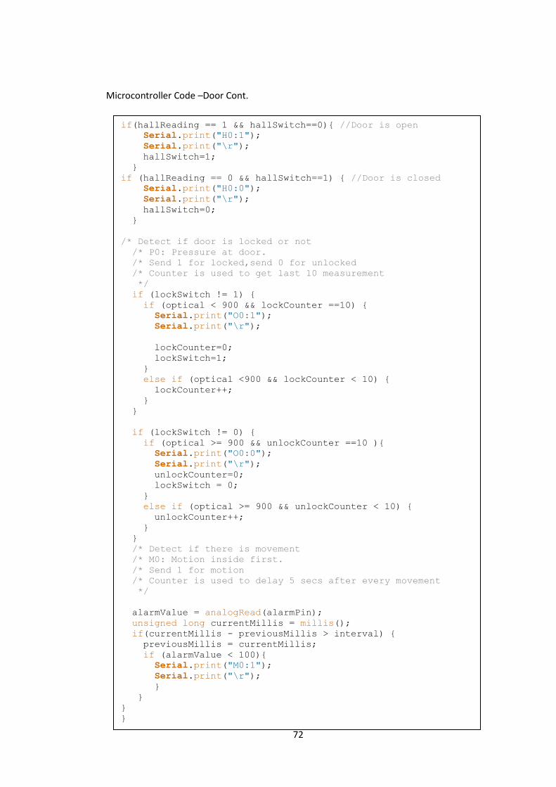
72
Microcontroller Code –Door Cont.
if(hallReading == 1 && hallSwitch==0){ //Door is open
Serial.print("H0:1");
Serial.print("\r");
hallSwitch=1;
}
if (hallReading == 0 && hallSwitch==1) { //Door is closed
Serial.print("H0:0");
Serial.print("\r");
hallSwitch=0;
}
/* Detect if door is locked or not
/* P0: Pressure at door.
/* Send 1 for locked,send 0 for unlocked
/* Counter is used to get last 10 measurement
*/
if (lockSwitch != 1) {
if (optical < 900 && lockCounter ==10) {
Serial.print("O0:1");
Serial.print("\r");
lockCounter=0;
lockSwitch=1;
}
else if (optical <900 && lockCounter < 10) {
lockCounter++;
}
}
if (lockSwitch != 0) {
if (optical >= 900 && unlockCounter ==10 ){
Serial.print("O0:0");
Serial.print("\r");
unlockCounter=0;
lockSwitch = 0;
}
else if (optical >= 900 && unlockCounter < 10) {
unlockCounter++;
}
}
/* Detect if there is movement
/* M0: Motion inside first.
/* Send 1 for motion
/* Counter is used to delay 5 secs after every movement
*/
alarmValue = analogRead(alarmPin);
unsigned long currentMillis = millis();
if(currentMillis - previousMillis > interval) {
previousMillis = currentMillis;
if (alarmValue < 100){
Serial.print("M0:1");
Serial.print("\r");
}
}
}
}

73
Microcontroller Code -Outside
/* Uno 4
/* Ambient Temp,Photosensor
/* Used at outside
/* M.Ozge Kaya; Informatics Institute,METU
*/
#include <Wire.h>
int tmp102Address = 0x48;
byte res;
int val;
int photoPin =A0;
int photoRead =0;
void setup(){
Serial.begin(57600);
Wire.begin();
}
void loop(){
/* Detect outside temp.
/* T1: Outside temperetaure
/* Send every 8 sec.
*/
Wire.requestFrom(tmp102Address,2);
byte MSB = Wire.receive();
byte LSB = Wire.receive();
int TemperatureSum = ((MSB << 8) | LSB) >> 4; //it's a 12bit
int, using two's compliment for negative
float celsius = TemperatureSum*0.0625;
Serial.print("T1:");
Serial.print(celsius);
Serial.print("\r");
delay(4000);
/* Detect outside ambient light.
/* L1: Outside light.
/* Send every 8 sec.
*/
photoRead= analogRead(photoPin);
Serial.print("L1:");
Serial.print(photoRead);
Serial.print("\r");
delay(4000);
}

74
Microcontroller Code –Inside Wall
/* Uno 3
/* Ambient Temp,Photosensor,Electret Microhpone
/* Used at inside
/* M.Ozge Kaya, Informatic Institute,METU
*/
#include <Wire.h>
int tmp102Address = 0x48;
byte res;
int val;
const int ledPin = 13;
const int electret = A0;
const int photo =A1;
int electretReading = 0;
int photoReading =0;
int electretMax = 0;
int electretMin = 1023;
int electretThresholdHIGH =100;
int electretThresholdMED =50;
int electretThresholdLOW ;
int noiseLevel;
int lastNoiseLevel=50;
long previousMillis = 0;
long interval = 8000;
void setup() {
Serial.begin(57600);
Wire.begin();
//Calibration for Electret
while (millis() < 3000) {
electretThresholdLOW = analogRead(electret);
// record the maximum sensor value
if (electretThresholdLOW > electretMax) {
electretMax = electretThresholdLOW;
}
}
// signal the end of the calibration period
electretThresholdLOW = electretMax;
Serial.println("Calibration Completed");
Serial.print("Background Noise Level:");
Serial.println(electretThresholdLOW,DEC);
}

75
Microcontroller Code –Inside Wall Cont.
void loop() {
/* Detect inside noise.
/* E0: Inside Noise
/*
*/
electretReading = analogRead(electret);
if ((electretReading >= electretThresholdLOW)) {
Serial.print("E0:");
Serial.print(electretReading-electretThresholdLOW);
Serial.print("\r");
delay(500);
}
unsigned long currentMillis = millis();
if(currentMillis - previousMillis > interval) {
previousMillis = currentMillis;
/* Detect inside ambient light.
/* L0: Inside light.
/* Send every 8 sec.
*/
photoReading=analogRead(photo);
Serial.print("L0:");
Serial.print(photoReading);
Serial.print("\r");
/* Detect inside temp.
/* T0: Outside temperetaure
/* Send every 8 sec.
*/
Wire.requestFrom(tmp102Address,2);
byte MSB = Wire.receive();
byte LSB = Wire.receive();
int TemperatureSum = ((MSB << 8) | LSB) >> 4; //it's a
12bit int, using two's compliment for negative
float celsius = TemperatureSum*0.0625;
Serial.print("S0:");
Serial.print(celsius);
Serial.print("\r");
}
}

76
Microcontroller Code –Inside, Ceiling
/* Uno 2 Ic2
/* PIR,Photosensor
/* Used at inside
/* M.Ozge Kaya;Informatics Intstitute,METU
*/
int timer = 500;
int alarmPin = A0;
int alarmValue = 0;
long previousMillis = 0;
long interval = 6000;
int photoReading =0;
const int photo =A1;
void setup(){
Serial.begin(57600);
pinMode(alarmPin, INPUT);
delay (3000);
}
void loop(){
/* Detect motion
/* M1: PIR Motion
/* Send every 2 sec.
*/
alarmValue = analogRead(alarmPin);
if (alarmValue < 100){
Serial.print("M1:1");
Serial.print("\r");
delay(2000);
}
unsigned long currentMillis = millis();
if(currentMillis - previousMillis > interval) {
previousMillis = currentMillis;
/* Detect inside ambient light.
/* L2: Inside light.
/* Send every 8 sec.
*/
photoReading=analogRead(photo);
Serial.print("L2:");
Serial.print(photoReading);
Serial.print("\r");
}
}

77
Appendix C : Rules in Drools Rule Language
CE 1: Lecture will be delayed
rule "dersGecikecek"
when
CurrentState(timeOfLecture=="S1") from entry-point
DEFAULT
CurrentState(numberOfStudents <= 3) from entry-point
DEFAULT ||
Number( doubleValue < 17) from accumulate(
SensorEvent(sensorName == "Temp0",$data : data) over
window:length( 4 ) from entry-point classroom,
average( $data ) ) ||
$eventA : SensorEvent(sensorName == "Optical0") over
window:length (1) from entry-point classroom
SensorEvent(data == 1) from $eventA
then
System.out.println( "DROOLS:Ders Gecikecek");
Main.sendDroolsJMS("DROOLS:Ders Gecikecek");
end
CE 2: Lesson Started
rule "dersBasladi"
when
not(DroolsEvent(event == "dersBasladi") from entry-point
DEFAULT)
$eventA : SensorEvent(sensorName=="Hall0") over
window:length(1) from entry-point classroom
SensorEvent(data == 1) from $eventA
$state : CurrentState(numberOfStudents >= 6,timeOfLecture ==
"ST",isInstructerThere==true) from entry-point DEFAULT
then
System.out.println( "DROOLS:Ders Basladi");
Main.sendToJMSText("DERS BASLADI","state");
Main.sendDroolsJMS("DROOLS:Ders Basladi");
Main.addEventDersBasladi();
Main.retractEventAraBitti();
Main.retractEventDersBitti();
end

78
CE 3 :Break given
rule "araVerildi"
when
not(CurrentState(timeOfLecture=="E15") from entry-point
DEFAULT)
not(DroolsEvent(event == "araVerildi") from entry-point
DEFAULT)
not(DroolsEvent(event == "dersBitti") from entry-point
DEFAULT)
not(DroolsEvent(event=="araBitti") from entry-point DEFAULT)
$eventB : DroolsEvent(event=="dersBasladi" ) from entry-point
DEFAULT
$eventA : SensorEvent(sensorName=="Hall0",data == 0,this
after[30m,90m] $eventB) from entry-point classroom
$eventD : SensorEvent(sensorName == "Infrared0",data ==
1,this after[1s,120s] $eventA) from entry-point classroom
then
System.out.println( "DROOLS:Ara Verildi");
Main.sendToJMSText("ARA VERILDI","state");
Main.sendDroolsJMS("DROOLS:Ara Verildi");
Main.retractEventAraBitti();
Main.addEventAraVer();
end
CE 4: Break ended
rule "araBitti"
when
not(DroolsEvent(event=="araBitti" ) from entry-point DEFAULT)
$eventB : DroolsEvent(event == "araVerildi") from entry-point
DEFAULT
$eventA : SensorEvent(sensorName=="Hall0",data == 1,this
after[5m,30m] $eventB) over window:length(1) from entry-point
classroom
then
System.out.println( "DROOLS:Ara Bitti");
Main.sendToJMSText("ARA BITTI","state");
Main.sendDroolsJMS("DROOLS:Ara Bitti");
Main.addEventAraBitti();
Main.retractEventAra();
End

79
CE5: Lecture Ended
rule "dersBitti"
when
not(DroolsEvent(event=="dersBitti" ) from entry-point
DEFAULT)
$eventA : DroolsEvent(event == "dersBasladi") from entry-
point DEFAULT
( CurrentState(timeOfLecture=="E15") from entry-point DEFAULT
||
CurrentState(timeOfLecture=="ET") from entry-point DEFAULT)
$eventB : SensorEvent(sensorName=="Hall0") over
window:legth(1) from entry-point classroom
$eventD : SensorEvent(data == 0) from $eventB
$eventC : SensorEvent(sensorName == "Infrared0",data ==
1,this after[1s,120s] $eventB) from entry-point classroom
CurrentState(isInstructerThere==false) from entry-point
DEFAULT
CurrentState(numberOfStudents <= 3) from entry-point DEFAULT
then
System.out.println( "DROOLS:Ders Bitti");
Main.sendToJMSText("DERS BITTI","state");
Main.sendDroolsJMS("DROOLS:Ders Bitti");
Main.addEventDersBitti();
Main.retractEventAraBitti();
Main.retractEventDersBasladi();
end
CE6: Lecture finished early
rule "dersErkenBitti"
when
not( CurrentState(timeOfLecture=="E15"))
not( CurrentState(timeOfLecture=="ET"))
not(DroolsEvent(event=="dersBitti" ) from entry-point
DEFAULT)
$eventA : DroolsEvent(event == "dersBasladi") from entry-
point DEFAULT
$eventB : SensorEvent(sensorName=="Hall0",data == 0) from
entry-point classroom
$eventC : SensorEvent(sensorName == "Infrared0",data ==
1,this after [1s] $eventB) from entry-point classroom
CurrentState(isInstructerThere==false)
CurrentState(numberOfStudents <= 3)
then
System.out.println( "DROOLS:Ders Erken Bitti");
Main.sendToJMSText("DERS ERKEN BITTI","state");
Main.sendDroolsJMS("DROOLS:Ders Erken Bitti");
Main.addEventDersBitti();
Main.retractEventAraBitti();
Main.retractEventDersBasladi();
end

80
CE7: Day ended
rule "gunBitti"
when
$eventC : DroolsEvent(event=="dersBitti" ) from entry-point
DEFAULT
$eventA : CurrentState(isLastCourse==true) from entry-
point DEFAULT
not(SensorEvent(sensorName == "Motion0",data >= 0,this after
[10m,15m] $eventC) from entry-point classroom)
not(SensorEvent(sensorName == "Motion1",data >= 0,this after
[10m,15m] $eventC) from entry-point classroom)
Number( doubleValue < 50) from accumulate(
SensorEvent(sensorName == "Electret0",$data : data) over
window:time(60s) from entry-point classroom,
average( $data ) )
then
System.out.println( "DROOLS:GUN Bitti");
Main.sendToJMSText("GUN BITTI","state");
Main.sendDroolsJMS("DROOLS:Gun Bitti");
Main.retractEventDersBitti();
Main.addEventGunBitti();
Main.changeCurrentState("false","isLastLecture");
System.out.println("görevliyi kilit için çağır");
end
CE8: Classroom Check
rule "sınıfKontrol"
when
$eventA : DroolsEvent(event=="gunBitti" ) from entry-point
DEFAULT
$eventB : SensorEvent(sensorName=="Optical0",this after
[10m,60m] $eventA) over window:length (1) from entry-point
classroom
SensorEvent(data == 1) from $eventB
$eventC : SensorEvent(sensorName=="Motion0",data >= 0,this
after [0h,8h] $eventB) from entry-point classroom ||
$eventD : SensorEvent(sensorName=="Motion1",data >= 0,this
after [0h,8h] $eventB) from entry-point classroom ||
Number( doubleValue > 50) from accumulate(
SensorEvent(sensorName == "Electret0",$data : data,this after
$eventB) over window:time(60s) from entry-point classroom,
average( $data ) ) ||
not(SensorEvent(sensorName=="Light0",data <= 200,this after
[0h,8h] $eventB) from entry-point classroom) ||
not(SensorEvent(sensorName=="Light2",data <= 200,this after
[0h,8h] $eventB) from entry-point classroom)
then
System.out.println( "DROOLS:SINIFI KONTROL ET");
Main.sendToJMSText("SINIFI KONTROL ET","state");
Main.sendDroolsJMS("DROOLS:SINIFI KONTROL ET");
end

81
CE9: Day started
rule "gunbasladi"
when
$eventA : DroolsEvent(event=="gunBitti" ) from entry-point
DEFAULT
$eventB : DroolsEvent(event=="dersBasladi" ) from entry-point
DEFAULT
then
System.out.println( "DROOLS:Gun Basladi");
Main.sendDroolsJMS("DROOLS:Gün Basladi");
Main.addEventGunBasladi();
Main.retractEventGunBitti();
end
AR1: Open the curtains
rule "perdeAc"
when
Number( doubleValue < 500) from accumulate(
SensorEvent(sensorName == "Light0",$data : data) over
window:length( 10 ) from entry-point classroom,
average( $data ) ) || Number( doubleValue < 500) from
accumulate(
SensorEvent(sensorName == "Light2",$data : data) over
window:length( 10 ) from entry-point classroom,
average( $data ) )
Number( doubleValue > 600) from accumulate(
SensorEvent(sensorName == "Light1",$data : data) over
window:length( 10 ) from entry-point classroom,
average( $data ) )
then
System.out.println( "DROOLS:Dış ortam aydınlık perdeleri
açın.");
Main.sendDroolsJMS("DROOLS:perdeleri acin.");
end

82
AR2 :Open the lights
rule "isikAc"
when
Number( doubleValue < 500) from accumulate(
SensorEvent(sensorName == "Light0",$data : data) over
window:length( 10 ) from entry-point classroom,
average( $data ) ) || Number( doubleValue < 500) from
accumulate(
SensorEvent(sensorName == "Light2",$data : data) over
window:length( 10 ) from entry-point classroom,
average( $data ) )
Number( doubleValue < 600) from accumulate(
SensorEvent(sensorName == "Light1",$data : data) over
window:length( 10 ) from entry-point classroom,
average( $data ) )
then
System.out.println( "DROOLS:Dış ortam karanlık ışıkları
açın."); //Main.sendDroolsJMS("DROOLS:isiklari acin.");
Main.sendDroolsJMS("DROOLS:Isiklari acin.");
end
AR3 : Open the window
rule "camAc"
when
Number( doubleValue >= 28) from accumulate(
SensorEvent(sensorName == "Temp0",$data : data) over
window:length( 10 ) from entry-point classroom,
average( $data ) )
Number( doubleValue <= 24) from accumulate(
SensorEvent(sensorName == "Temp1",$data : data) over
window:length( 10 ) from entry-point classroom,
average( $data ) )
Number( doubleValue <= 19) from accumulate(
SensorEvent(sensorName == "Temp1",$data : data) over
window:length( 10 ) from entry-point classroom,
average( $data ) )
then
System.out.println( "DROOLS:İçerisi çok sıcak camı
açın.");
Main.sendDroolsJMS("DROOLS:Cami acin.");
end

83
AR4 : Run air conditioner
rule "klimaAc"
when
Number( doubleValue >= 28) from accumulate(
SensorEvent(sensorName == "Temp0",$data : data) over
window:length( 10 ) from entry-point classroom,
average( $data ) )
Number( doubleValue >= 24) from accumulate(
SensorEvent(sensorName == "Temp1",$data : data) over
window:length( 10 ) from entry-point classroom,
average( $data ) )
then
System.out.println( "DROOLS:İçerisi çok sıcak klima
açın.");
Main.sendDroolsJMS("DROOLS:Klima acin.");
end
AR5 : Run heater
rule "isiticiAc"
when
Number( doubleValue <= 20) from accumulate(
SensorEvent(sensorName == "Temp0",$data : data) over
window:length( 10 ) from entry-point classroom,
average( $data ) )
Number( doubleValue <= 22) from accumulate(
SensorEvent(sensorName == "Temp1",$data : data) over
window:length( 10 ) from entry-point classroom,
average( $data ) )
then
System.out.println( "DROOLS:İçerisi çok soğuk ısıtıcı
açın.");
Main.sendDroolsJMS("DROOLS:Isıtıcı acin.");
end

84
TEZ FOTOKOPİSİ İZİN FORMU
ENSTİTÜ
Fen Bilimleri Enstitüsü
Sosyal Bilimler Enstitüsü
Uygulamalı Matematik Enstitüsü
Enformatik Enstitüsü
Deniz Bilimleri Enstitüsü
YAZARIN
Soyadı: KAYA
Adı : MUAMER ÖZGE
Bölümü : BİLİŞİM SİSTEMLERİ
TEZİN ADI (İngilizce): A Complex Event Processing Framework
Implementation Using Heterogeneous Devices In Smart Environments
TEZİN TÜRÜ : Yüksek Lisans Doktora
1. Tezimin tamamından kaynak gösterilmek şartıyla fotokopi alınabilir.
2. Tezimin içindekiler sayfası, özet, indeks sayfalarından ve/veya bir
bölümünden kaynak gösterilmek şartıyla fotokopi alınabilir.
3. Tezimden bir bir (1) yıl süreyle fotokopi alınamaz.
TEZİN KÜTÜPHANEYE TESLİM TARİHİ:..........................................