a comparative study between passive and electronic ... · a comparative study between passive and...
TRANSCRIPT

A comparative study between passive and electronic radiation dose detectors
M.J. García1, X. Rúa2 and X. Queralt1 1ALBA Synchrotron-CELLS, Carretera BP-1413, km 3, 08290 Cerdanyola del Vallès, Barcelona, Spain
2ACPRO - Asesoría y Control en Protección Radiológica, S.L., C/ Rafael Batlle, 24, 08017 Barcelona, Spain Abstract The radiation fields produced by synchrotron accelerators like ALBA are complex fields composed of electrons, gamma and neutrons of a wide energy range, with an important pulsed behaviour and very important spatial variations. The radiation detectors commonly used for radiation protection purposes at these facilities usually include an ensemble of active and passive detectors with different responses, when compared one to each other, from their energy response to their behaviour in presence of pulsed fields. A comparative study has been performed to analyse accumulated dose differences between the active and passive detectors in use in ALBA at 2 different locations of the electron linear accelerator (LINAC) and next to the electron Storage ring (SR). The position selected for the LINAC case has been near to the Faraday cup inside the shielding bunker, where the primary electron beam has energy close to 110 MeV. Also 2 different positions were taken for the SR case, next to the Booster synchrotron to SR transfer line, where the electron energy is 3.0 GeV. To minimize the effect of the spatial radiation field distribution on any of the detectors used, both for the LINAC and for the SR positions, all the detectors were placed in less than 1 meter circumference radius. A set of active detectors composed by an ionization chamber for gamma radiation and a 3He proportional counter for neutron radiation has been used at each selected position, with a total of 4 gamma ionization chambers and 4 neutron detectors. Each active detector has been surrounded (in close contact) by passive detectors sensitive to gamma and neutrons, oriented normally and orthogonally to the estimated incident radiation. Electronic personal dosimeters were also placed attached to the gamma detectors in normal incidence. The detectors have been exposed during 8h to non-specifically planed irradiation patterns, but while during a 24h shift dedicated to machine studies. Several beam injections and electron losses took place along the 24h. In this work we present the values for all the detectors depending on their relative position and related to the acceleration elements, and for the different irradiation conditions. 1. Introduction This paper describes the results of a comparative study that has been performed to analyse accumulated dose differences between the active and passive detectors in use in ALBA, which can be produced by highly pulsed behaviour of the fields present in ALBA accelerators. For further understanding of the results presented, a brief description of the acceleration system and of the radiation detectors in use at ALBA is given in this section. 1.1. Alba’s accelerators The Alba synchrotron facility is formed by a linear accelerator (LINAC) and two circular Booster and Storage accelerators that provide synchrotron light to a total of 7 beamlines. The LINAC accelerator is housed inside a separate bunker and it generates a pulsed electron beam up to 110 MeV. Its main parameters are described in Table 1. The 110 MeV beam is then injected into a circular Booster type accelerator, that increases the beam energy up to 3 GeV, which is ALBA’s nominal energy. The so accelerated beam is finally stored into the Storage ring and from there the synchrotron light is delivered to the 7 beamlines. Both Booster and Storage rings are housed inside the same bunker, namely the Tunnel. A deeper description of the ALBA’s acceleration system is given in [1], [2], [3] and [4].
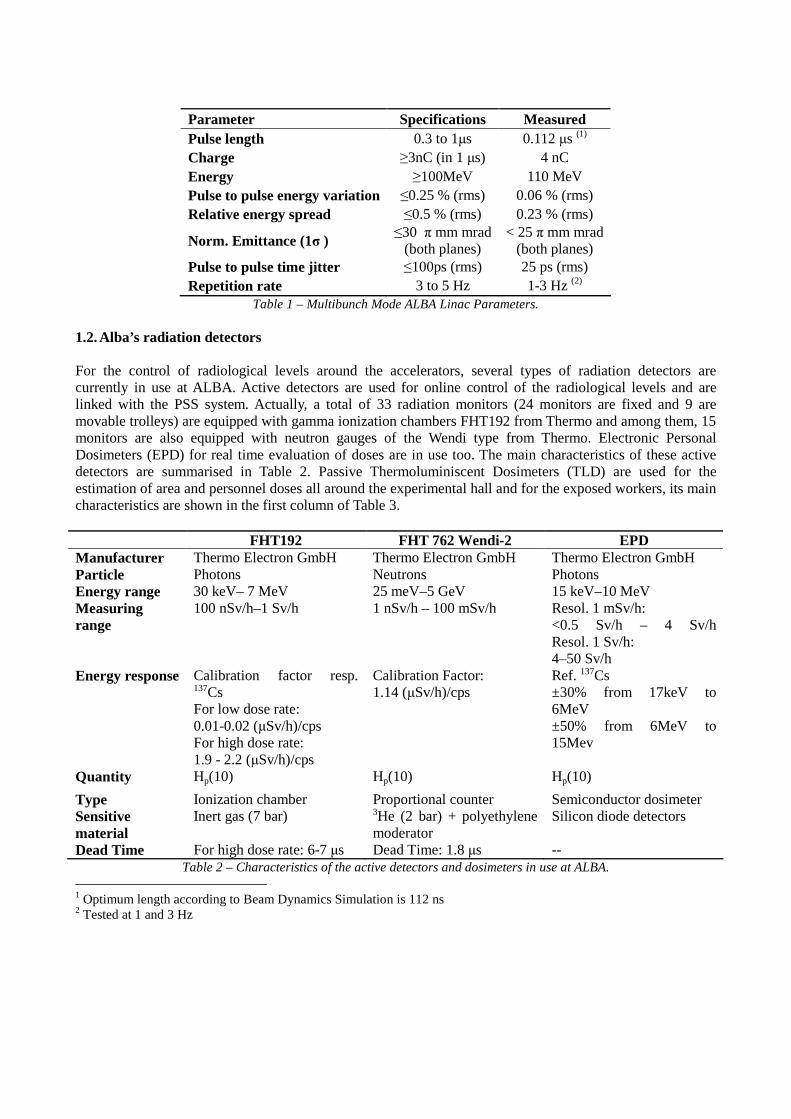
Parameter Specifications Measured Pulse length 0.3 to 1µs 0.112 µs (1) Charge ≥3nC (in 1 µs) 4 nC Energy ≥100MeV 110 MeV Pulse to pulse energy variation ≤0.25 % (rms) 0.06 % (rms) Relative energy spread ≤0.5 % (rms) 0.23 % (rms)
Norm. Emittance (1σ ) ≤30 π mm mrad
(both planes) < 25 π mm mrad
(both planes) Pulse to pulse time jitter ≤100ps (rms) 25 ps (rms) Repetition rate 3 to 5 Hz 1-3 Hz (2)
Table 1 – Multibunch Mode ALBA Linac Parameters. 1.2. Alba’s radiation detectors
For the control of radiological levels around the accelerators, several types of radiation detectors are currently in use at ALBA. Active detectors are used for online control of the radiological levels and are linked with the PSS system. Actually, a total of 33 radiation monitors (24 monitors are fixed and 9 are movable trolleys) are equipped with gamma ionization chambers FHT192 from Thermo and among them, 15 monitors are also equipped with neutron gauges of the Wendi type from Thermo. Electronic Personal Dosimeters (EPD) for real time evaluation of doses are in use too. The main characteristics of these active detectors are summarised in Table 2. Passive Thermoluminiscent Dosimeters (TLD) are used for the estimation of area and personnel doses all around the experimental hall and for the exposed workers, its main characteristics are shown in the first column of Table 3. FHT192 FHT 762 Wendi-2 EPD Manufacturer Thermo Electron GmbH Thermo Electron GmbH Thermo Electron GmbH Particle Photons Neutrons Photons Energy range 30 keV– 7 MeV 25 meV–5 GeV 15 keV–10 MeV Measuring range
100 nSv/h–1 Sv/h 1 nSv/h – 100 mSv/h Resol. 1 mSv/h: <0.5 Sv/h – 4 Sv/h Resol. 1 Sv/h: 4–50 Sv/h
Energy response Calibration factor resp. 137Cs For low dose rate: 0.01-0.02 (µSv/h)/cps For high dose rate: 1.9 - 2.2 (µSv/h)/cps
Calibration Factor: 1.14 (µSv/h)/cps
Ref. 137Cs ±30% from 17keV to 6MeV ±50% from 6MeV to 15Mev
Quantity Hp(10) Hp(10) Hp(10)
Type Ionization chamber Proportional counter Semiconductor dosimeter Sensitive material
Inert gas (7 bar) 3He (2 bar) + polyethylene moderator
Silicon diode detectors
Dead Time For high dose rate: 6-7 µs Dead Time: 1.8 µs -- Table 2 – Characteristics of the active detectors and dosimeters in use at ALBA.
1 Optimum length according to Beam Dynamics Simulation is 112 ns 2 Tested at 1 and 3 Hz

In order to extend the study to other type of passive dosimeter available in the market, special TLDs with spherical geometry (TLD_spherical) were provided by Centro de Dosimetría company and mixed dosimeters with a Radiophotoluminscent gamma detector (IPN_gamma) and a solid-state nuclear track detector for neutrons (IPN_n) coupled in the same badge were obtained from IPN Orsay. The main characteristics of these dosimeters can be found in Table 3.
TLD TLD_Spherical IPN_gamma IPN_n Manufacturer Centro de
Dosimetría Centro de Dosimetría
IPN Orsay IPN Orsay
Particle Photons and beta Photons Photons Neutrons Energy range 15 keV - 7 MeV E>20 keV 50 keV à 40 MeV Measuring range 10 µGy - 10 Gy 50 µSv - 10 Sv 50 µSv - 1 Sv 0.1 - 250 mSv Energy response Ref. Cs-137
±10% from 20keV to 662keV
Ref. Cs-137 ±20% from 20keV to 662keV
No data available No data available
Quantity Hp(10) Hp(10) Hp(10) Hp(10)
Sensitive material Thermoluminiscent LiF
Thermoluminiscent LiF
Radiophotoluminiscent glass
Solid-state nuclear track detector and a polyethylene radiator
Table 3 – Characteristics of the passive dosimeters in use routinely at ALBA (TLD) and for the present study. 2. Methodology In order to analyse accumulated dose differences between the active and passive detectors described above, the detectors have been exposed in groups at 2 different locations near the electron linear accelerator (LINAC) and next to the electron Storage Ring (SR). The radiation monitors and dosimeters have been exposed during 8h runs to non-specifically planed irradiation patterns, but during 24h shifts dedicated to machine studies, so no specific beam time was allocated for this study. Several beam injections and electron losses took place along the 24h. The operation times of the different accelerators during the runs where the study took place are summarised in Table 4. As we can see, the operation time of each accelerator during each run varied widely, due to the different machine studies that were done in each run. The short operation time for the LINAC accelerator during runs 1-3, obliged to plan 3 longer extra runs, runs 4-6, in order to expose the LINAC detectors to a significant dose. The LINAC’s run with longest operation time was run 6 and the longest SR run was run 3. LINAC BOOSTER STORAGE RING Run Duration
(h) Operation (h) Maximum
charge (nC/pulse)
Operation (h)
Maximum current (mA)
Operation (h)
Maximum current (mA)
Integrated charge
(C) 1 8.00 1.40 1.18 0.90 0.78 0.08 20.33 3 2 7.75 0.25 1.13 0.23 0.72 5.85 120.7 2332 3 8.08 0.65 1.14 0.20 0.53 6.92 120.5 2887 4 7.00 3.27 1.24 -- -- -- -- -- 5 17.00 1.10 1.24 -- -- -- -- -- 6 79.00 4.57 1.24 -- -- -- -- --
Table 4 – Operation times of the different accelerators during the runs were the study took place. 2.1. Irradiation places and positions Two places were selected for the LINAC case near the Faraday cup inside the shielding bunker, where the primary electron beam has energy close to 110 MeV. Another 2 different locations were taken for the Storage Ring case, next to the Booster to Storage Ring transfer line, where the electron energy is 3.0 GeV. To
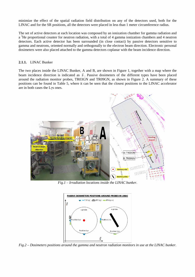
minimize the effect of the spatial radiation field distribution on any of the detectors used, both for the LINAC and for the SR positions, all the detectors were placed in less than 1 meter circumference radius. The set of active detectors at each location was composed by an ionization chamber for gamma radiation and a 3He proportional counter for neutron radiation, with a total of 4 gamma ionization chambers and 4 neutron detectors. Each active detector has been surrounded (in close contact) by passive detectors sensitive to gamma and neutrons, oriented normally and orthogonally to the electron beam direction. Electronic personal dosimeters were also placed attached to the gamma detectors coplanar with the beam incidence direction. 2.1.1. LINAC Bunker The two places inside the LINAC Bunker, A and B, are shown in Figure 1, together with a map where the beam incidence direction is indicated as s
r. Passive dosimeters of the different types have been placed
around the radiation monitor probes, TR03GN and TR09GN, as shown in Figure 2. A summary of these positions can be found in Table 5, where it can be seen that the closest positions to the LINAC accelerator are in both cases the Lγs ones.
Fig.1 – Irradiation locations inside the LINAC bunker.
Fig.2 – Dosimeters positions around the gamma and neutron radiation monitors in use at the LINAC bunker.
Point Place Position Accelerator Along … # Types of
dosemeter per position
Distance to the beam chamber (cm)
Radiation Monitor
1 Lγs LINAC s 4 215.0 TR03GN 2 Lγx LINAC x 2 225.0 TR03GN 3 Lns LINAC s 2 240.3 TR03GN 4
A
Lnx LINAC x 1 251.5 TR03GN 5 Lγs LINAC s 4 195.0 TR09GN 6 Lγx LINAC x 2 205.0 TR09GN 7 Lns LINAC s 2 220.3 TR09GN 8
B
Lnx LINAC x 1 231.5 TR09GN Table 5 – Summary of all the LINAC positions according to Figure 3.
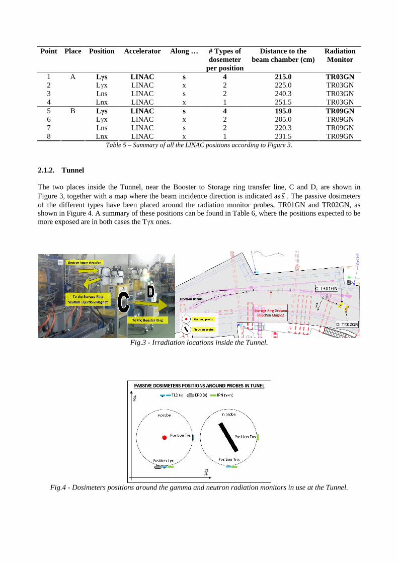
2.1.2. Tunnel The two places inside the Tunnel, near the Booster to Storage ring transfer line, C and D, are shown in Figure 3, together with a map where the beam incidence direction is indicated ass
r. The passive dosimeters
of the different types have been placed around the radiation monitor probes, TR01GN and TR02GN, as shown in Figure 4. A summary of these positions can be found in Table 6, where the positions expected to be more exposed are in both cases the Tγx ones.
Fig.3 - Irradiation locations inside the Tunnel.
Fig.4 - Dosimeters positions around the gamma and neutron radiation monitors in use at the Tunnel.
Point Place Position Accelerator Along … # Type of
dosemeter per position
Distance to the beam chamber
(cm)
Radiation Monitor
9 Tγs Tunnel s 1 20.0 TR01GN 10 Tγx Tunnel x 4 10.0 TR01GN 11 Tns Tunnel s 1 48.3 TR01GN 12
C
Tnx Tunnel x 2 37.0 TR01GN 13 Tγs Tunnel s 1 48.3 TR02GN 14 Tγx Tunnel x 3 (No Sph_TLD) 38.3 TR02GN 15 Tns Tunnel s 1 22.5 TR02GN 16
D
Tnx Tunnel x 2 11.3 TR02GN Table 6 - Summary of all the Tunnel positions according to Figure 6.
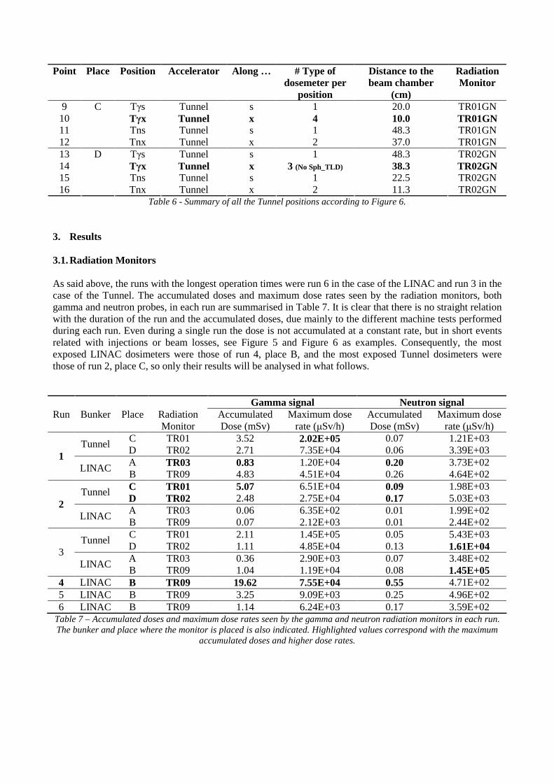
3. Results 3.1. Radiation Monitors As said above, the runs with the longest operation times were run 6 in the case of the LINAC and run 3 in the case of the Tunnel. The accumulated doses and maximum dose rates seen by the radiation monitors, both gamma and neutron probes, in each run are summarised in Table 7. It is clear that there is no straight relation with the duration of the run and the accumulated doses, due mainly to the different machine tests performed during each run. Even during a single run the dose is not accumulated at a constant rate, but in short events related with injections or beam losses, see Figure 5 and Figure 6 as examples. Consequently, the most exposed LINAC dosimeters were those of run 4, place B, and the most exposed Tunnel dosimeters were those of run 2, place C, so only their results will be analysed in what follows.
Gamma signal Neutron signal Run Bunker Place Radiation
Monitor Accumulated Dose (mSv)
Maximum dose rate (µSv/h)
Accumulated Dose (mSv)
Maximum dose rate (µSv/h)
C TR01 3.52 2.02E+05 0.07 1.21E+03 Tunnel D TR02 2.71 7.35E+04 0.06 3.39E+03 A TR03 0.83 1.20E+04 0.20 3.73E+02
1 LINAC
B TR09 4.83 4.51E+04 0.26 4.64E+02 C TR01 5.07 6.51E+04 0.09 1.98E+03 Tunnel D TR02 2.48 2.75E+04 0.17 5.03E+03 A TR03 0.06 6.35E+02 0.01 1.99E+02
2 LINAC
B TR09 0.07 2.12E+03 0.01 2.44E+02 C TR01 2.11 1.45E+05 0.05 5.43E+03 Tunnel D TR02 1.11 4.85E+04 0.13 1.61E+04 A TR03 0.36 2.90E+03 0.07 3.48E+02
3 LINAC
B TR09 1.04 1.19E+04 0.08 1.45E+05 4 LINAC B TR09 19.62 7.55E+04 0.55 4.71E+02 5 LINAC B TR09 3.25 9.09E+03 0.25 4.96E+02 6 LINAC B TR09 1.14 6.24E+03 0.17 3.59E+02
Table 7 – Accumulated doses and maximum dose rates seen by the gamma and neutron radiation monitors in each run. The bunker and place where the monitor is placed is also indicated. Highlighted values correspond with the maximum
accumulated doses and higher dose rates.
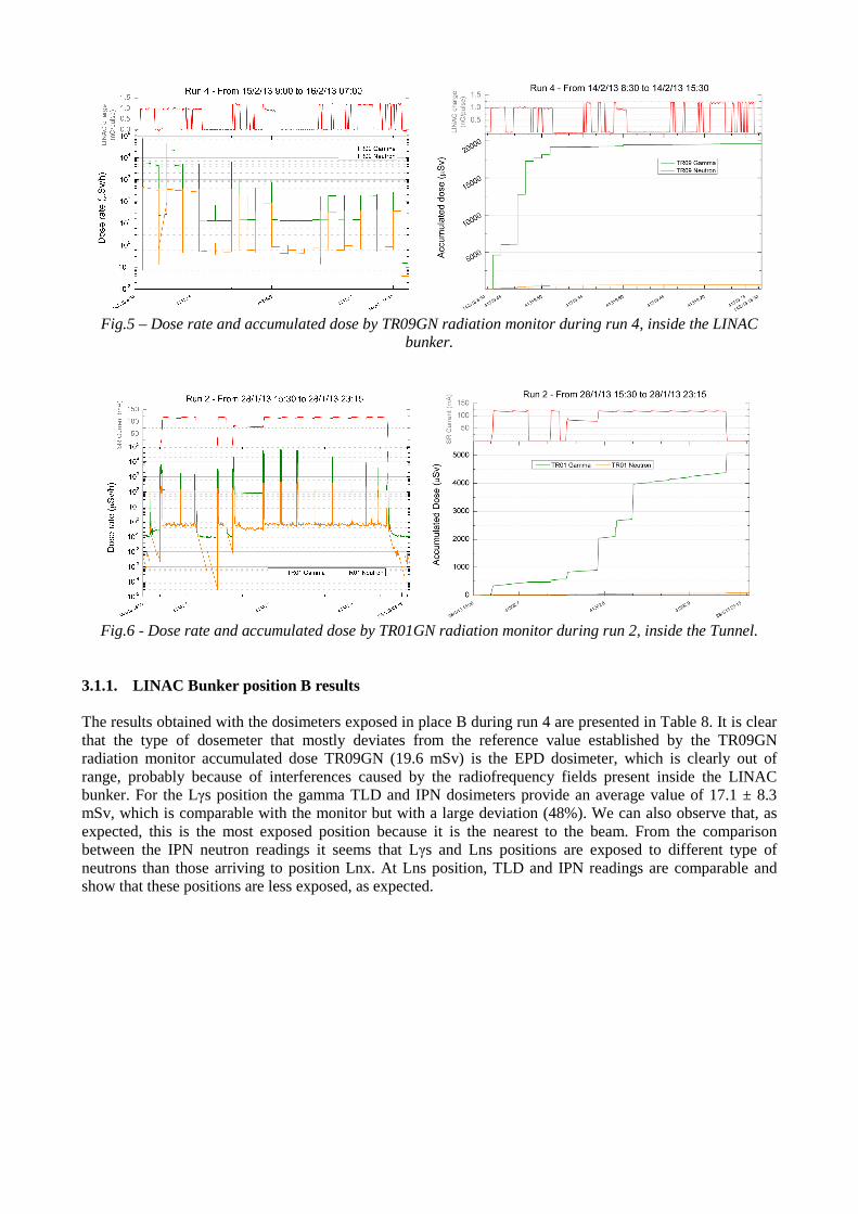
Fig.5 – Dose rate and accumulated dose by TR09GN radiation monitor during run 4, inside the LINAC
bunker.
Fig.6 - Dose rate and accumulated dose by TR01GN radiation monitor during run 2, inside the Tunnel.
3.1.1. LINAC Bunker position B results The results obtained with the dosimeters exposed in place B during run 4 are presented in Table 8. It is clear that the type of dosemeter that mostly deviates from the reference value established by the TR09GN radiation monitor accumulated dose TR09GN (19.6 mSv) is the EPD dosimeter, which is clearly out of range, probably because of interferences caused by the radiofrequency fields present inside the LINAC bunker. For the Lγs position the gamma TLD and IPN dosimeters provide an average value of 17.1 ± 8.3 mSv, which is comparable with the monitor but with a large deviation (48%). We can also observe that, as expected, this is the most exposed position because it is the nearest to the beam. From the comparison between the IPN neutron readings it seems that Lγs and Lns positions are exposed to different type of neutrons than those arriving to position Lnx. At Lns position, TLD and IPN readings are comparable and show that these positions are less exposed, as expected.

Place Position Detects Type HPM (mSv) Dev. from Rad. Mon. TLD 29.44 50% IPN 11.50 -41% γ EPD 1874 9451%
Lγs
n IPN 1.40 155% Lγx γ TLD 10.22 -48%
TLD 4.11 -79% γ
IPN 5.50 -72% Lns n IPN 1.60 191% γ IPN 2.30 -88%
B
Lnx n IPN 0.50 -9%
Table 8 – Results of the different dosimeters in place B, inside LINAC bunker and exposed during run 4, and their accumulated dose values deviations from the dose accumulated by the respective radiation monitor.
3.1.2. Tunnel position C results The results obtained with the dosimeters exposed in place C during run 2 are presented in Table 9. Again the type of dosemeter that mostly deviates from the reference value established by the TR01GN radiation monitor accumulated dose (5.1 mSv) is the EPD dosimeter, which is clearly out of range, probably because of interferences caused by the radiofrequency fields present inside the Tunnel. For the Tγx position the gamma TLD and IPN dosimeters provide an average value of 4.0 ± 0.9 mSv, which is comparable with the monitor with reasonable deviation (21%). It is also observed that, as expected, this is the most exposed position. The IPN neutron readings are below the detection limit; this is compatible with the low accumulated neutron dose seen by the neutron radiation monitor (0.09 mSv). The gamma TLD and IPN readings from the neutron gauge give an average value of: 4.5 ± 0.6 mSv, comparable with the gamma radiation monitor with 14% deviation and showing that gamma irradiation is more uniform in this tunnel location than in the LINAC bunker.
Place Position Detects Type HPM Dev from Rad. Mon. TLD 5.46 8%
Sph TLD 3.40 -33% IPN 4.20 -17%
γ
EPD 0.001 -100% Tγx
n IPN 0.00 Tγs γ TLD 2.88 -43%
TLD 5.26 4% γ
IPN 4.70 -7% Tnx n IPN 0.00 γ IPN 3.60 -29%
C
Tns n IPN 0.00
Table 9 - Results of the different dosimeters in place C, inside the Tunnel and exposed during run 2, and their accumulated dose values deviations from the dose accumulated by the respective radiation monitor.

3.1.3. Linearity for gamma dosimeters A third analysis has also been done to check the dose linearity behaviour of the gamma dosimeters. For this, the data from the gamma TLD and IPN dosimeters have been considered, including all runs and all positions inside the LINAC bunker. The results are plotted in Figure 7, and from them we cannot conclude a clear linear behaviour, especially at lower doses where fluctuations are relatively important. We must take into account that irradiation patterns may have varied hugely from one run to another and that for a conclusive study more data is needed in the range between 5 – 20 mSv.
Fig.7 – Linearity of the accumulated dose seen by all TLD and IPN gamma dosimeters exposed inside the
LINAC bunker. Conclusions Radiation fields produced during routine use of the accelerators are spatially complex and sometimes with highly pulsed time structure so active detectors functionality can be compromised. We have seen that the radiation monitors dose accumulation pattern follows the injection process inside the LINAC bunker & Tunnel. In general, the accumulated doses obtained with the so-called «ALBA radiation monitors», FHT192 and FHT 762 Wendi-2 probes, are comparable with those obtained with the gamma TLD and IPN passive dosimeters, once uncertainties are taken into account. However, EPD active dosimeters were not able to work under such extreme irradiation conditions. The irradiation conditions did not allow performing a complete linearity study of all dosimeters response. It seems clear that it would be interesting to repeat the study in beam dedicated shifts that allow controlling the irradiation conditions in order to:
• Analyse if the EPD active dosimeters are able to work under more controlled irradiation conditions • Perform further tests to compare the responses of planar and spherical TLD • Achieve irradiation conditions in which neutron production is more important to ensure statistical
significance in neutron passive dosimeters readings • Expand the range of accumulated doses to complete a linearity study of all dosimeters response
Acknowledgements We are especially indebted to the ALBA Accelerator Division and to the Centro de Dosimetría company for providing us with test dosimeters not available commercially.

References [1] F. Pérez, “First year operation of the ALBA synchrotron light source”, Proceedings of IPAC2013, Shangai, China. [2] M. Pont, “Operation status of the ALBA synchrotron light source”, Proceedings of IPAC2012, New Orleans, Lousiana, USA. [3] F. Pérez, B. Bravo, “Commissioning of the ALBA storage ring RF system”, Proceedings of IPAC2011, San Sebastian, Spain. [4] J. Campmany, D. Einfeld, J. Marcos and V. Massana, “General description of IDs initially installed at ALBA”, Proceedings of IPAC2010, Kyoto, Japan.