a comparative study between direct spinel addition and in
TRANSCRIPT
A comparative study between Direct Spinel Addition and In-
Situ Spinelisation in a Low Cement High Alumina based
Refractory Castable
A thesis submitted in partial fulfillment of the requirements for the degree of
Bachelor of Technology
In
Ceramic Engineering
By
Antareep Sharma
Roll No.: 110CR0615
Under the supervision of
Prof. Ritwik Sarkar
Department of Ceramic Engineering
National Institute of Technology, Rourkela
2014
Pro
ject
Report
1
Pro
ject
Report
2
Pro
ject
Report
3
CONTENTS
Chapter Page No.
Objective 4
1 INTRODUCTION 5
1.1 Refractories 6
1.2 Unshaped Refractories 10
1.3 Castables 14
1.4 Calcium Aluminate Cement (Cac) Or High Alumina
Cement
16
1.5 Spinels 22
1.6 Tabular Alumina 26
1.7 Fused Magnesia 27
1.8 Use of Additives 28
2 EXPERIMENTAL PROCEDURE 30
2.1 Raw Material Collection 31
2.2 Casting and Sample Preparation 31
2.3 Flow Test 33
2.4 Determination of Density Variation 34
2.5 Determination of Cold Crushing Strength (CCS) 34
2.6 Phase Analysis by XRD 35
3 RESULTS AND DISCUSSIONS 36
4 SUMMARY 44
5 References 46

Pro
ject
Report
4
OBJECTIVE
The major objective of this work is to study the difference in properties of spinel containing high
alumina refractory castables, prepared by two different methods, namely in-situ spinelisation and
direct spinel addition. Also, the effect of two different types of cement, having different alumina
composition, was observed.

Pro
ject
Report
5
CHAPTER 1
INTRODUCTION
Pro
ject
Report
6
1.1 Refractories
A refractory material is one that can withstand and retains its strength at high temperatures.
Refractories are inorganic, nonmetallic, porous and heterogeneous materials composed of
thermally stable mineral aggregates, a binder phase and additives. ASTM C71 defines refractories
as "non-metallic materials having those chemical and physical properties that make them
applicable for structures, or as components of systems, that are exposed to environments above
1,000 °F (811 K; 538 °C). Refractory materials must be chemically and physically stable at high
temperatures. Depending on the operating environment, they need to be resistant to thermal shock,
be chemically inert, and/or have specific ranges of thermal conductivity and of the coefficient of
thermal expansion. The oxides of aluminium (alumina), silicon (silica) and magnesium (magnesia)
are the most important materials used in the manufacturing of refractories. Another oxide usually
found in refractories is the oxide of calcium (lime). Fire clays are also widely used in the
manufacture of refractories.
Refractories must be chosen according to the conditions they will face. Some applications require
special refractory materials. For example: Zirconia is used when the material must withstand
extremely high temperatures and higher abrasion or corrosion. Silicon carbide and carbon
(graphite) are two other refractory materials used in some very severe temperature conditions, but
they cannot be used in contact with oxygen, as they will oxidize and burn.
Binary compounds such as tungsten carbide or boron nitride can be very refractory. Hafnium
carbide is the most refractory binary compound known, with a melting point of 3890 °C. The
ternary compound tantalum hafnium carbide has one of the highest melting points of all known
compounds (4215 °C).
The main requirements for refractory materials are:
High temperature withstanding capacity
High load bearing capacity
Abrasion and wear resistance
Erosion and corrosion resistance

Pro
ject
Report
7
Higher thermal shock resistance
1.1.1 Uses of Refractories
Refractories are used by the metallurgy industry in the internal linings of furnaces, kilns, reactors
and other vessels for holding and transporting metal and slag. In non-metallurgical industries, the
refractories are mostly installed on fired heaters, hydrogen reformers, ammonia primary and
secondary reformers, cracking furnaces, incinerators, utility boilers, catalytic cracking units, coke
calciner, sulfur furnaces, air heaters, ducting, stacks, etc. Majority of these listed equipment
operate under high pressure, and operating temperature can vary from very low to very high
(approximately 900°F to 2900°F). The refractory materials are therefore needed to withstand
temperatures over and above these temperatures.
Thus the uses of refractories can be summarized in the following figure.
Fig -1.1: Typical Uses of Refractories
Pro
ject
Report
8
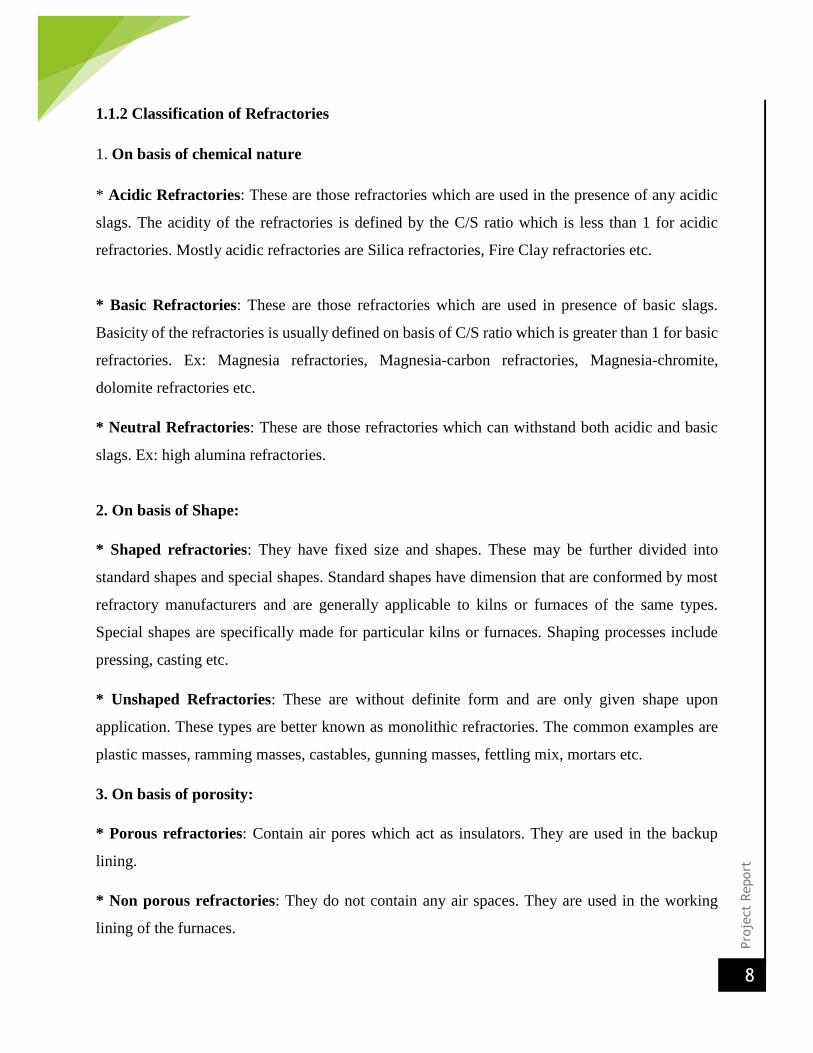
1.1.2 Classification of Refractories
1. On basis of chemical nature
* Acidic Refractories: These are those refractories which are used in the presence of any acidic
slags. The acidity of the refractories is defined by the C/S ratio which is less than 1 for acidic
refractories. Mostly acidic refractories are Silica refractories, Fire Clay refractories etc.
* Basic Refractories: These are those refractories which are used in presence of basic slags.
Basicity of the refractories is usually defined on basis of C/S ratio which is greater than 1 for basic
refractories. Ex: Magnesia refractories, Magnesia-carbon refractories, Magnesia-chromite,
dolomite refractories etc.
* Neutral Refractories: These are those refractories which can withstand both acidic and basic
slags. Ex: high alumina refractories.
2. On basis of Shape:
* Shaped refractories: They have fixed size and shapes. These may be further divided into
standard shapes and special shapes. Standard shapes have dimension that are conformed by most
refractory manufacturers and are generally applicable to kilns or furnaces of the same types.
Special shapes are specifically made for particular kilns or furnaces. Shaping processes include
pressing, casting etc.
* Unshaped Refractories: These are without definite form and are only given shape upon
application. These types are better known as monolithic refractories. The common examples are
plastic masses, ramming masses, castables, gunning masses, fettling mix, mortars etc.
3. On basis of porosity:
* Porous refractories: Contain air pores which act as insulators. They are used in the backup
lining.
* Non porous refractories: They do not contain any air spaces. They are used in the working
lining of the furnaces.

Pro
ject
Report
9
4. On basis of carbon content:
* Carbon containing refractories: They have some carbon content in their composition. They
are again classified on the basis of their oxidation resistance. Ex: Magnesia carbon refractories.
* Non carbon containing refractories: They do not have any carbon content in their composition.
5. On basis of heat withstanding capacity
This depends upon the percentage of Alumina content. They are further classified as:
* Low Heat Duty (25%-30% Al2O3)
* Medium Heat duty (30%-35% Al2O3)
* High heat duty (35%-40% Al2O3)
* Super heat duty (40%-45% Al2O3)
The heat withstanding capacity is directly proportional to the alumina content in the composition.
6. On basis of purity
It depends on the percentage of the major composition in the refractory. Ex: Al2O3-95% means it
is a 95% alumina in its composition.
1.1.3 SOME PROPERTIES OF REFRACTORIES
The properties of the refractory materials can be classified on 3 different types. They are:
Physical properties
Apparent porosity
Bulk density
Strength
Abrasion
Thermal properties
Thermal shock
Thermal Conductivity
Pro
ject
Report
10
Thermal diffusivity
Chemical properties
Corrosion
Erosion
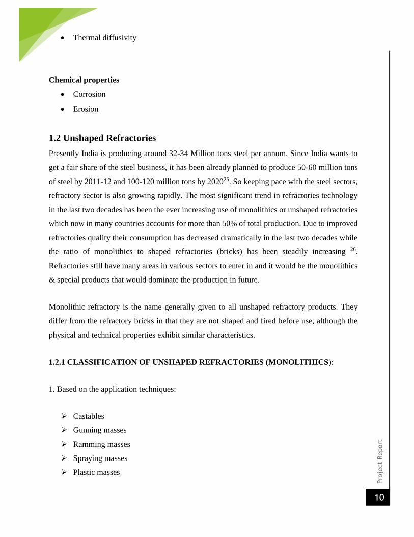
1.2 Unshaped Refractories
Presently India is producing around 32-34 Million tons steel per annum. Since India wants to
get a fair share of the steel business, it has been already planned to produce 50-60 million tons
of steel by 2011-12 and 100-120 million tons by 202025. So keeping pace with the steel sectors,
refractory sector is also growing rapidly. The most significant trend in refractories technology
in the last two decades has been the ever increasing use of monolithics or unshaped refractories
which now in many countries accounts for more than 50% of total production. Due to improved
refractories quality their consumption has decreased dramatically in the last two decades while
the ratio of monolithics to shaped refractories (bricks) has been steadily increasing 26.
Refractories still have many areas in various sectors to enter in and it would be the monolithics
& special products that would dominate the production in future.
Monolithic refractory is the name generally given to all unshaped refractory products. They
differ from the refractory bricks in that they are not shaped and fired before use, although the
physical and technical properties exhibit similar characteristics.
1.2.1 CLASSIFICATION OF UNSHAPED REFRACTORIES (MONOLITHICS):
1. Based on the application techniques:
Castables
Gunning masses
Ramming masses
Spraying masses
Plastic masses

Pro
ject
Report
11
2. Based on the binders used:
Cement bonded
Hydratable alumina bonded
Sol bonded
Phosphate bonded
Fig-1.2: Classification of unshaped refractories
1.2.2 Types of bonding present in the monolithic refractories:31
Hydraulic bonding
Chemical bonding
Ceramic bonding
Adhesive bonding
Pro
ject
Report
12
Coagulation bonding
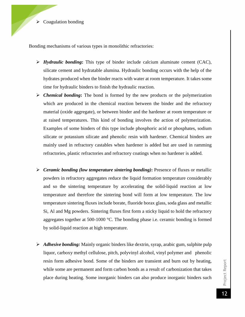
Bonding mechanisms of various types in monolithic refractories:
Hydraulic bonding: This type of binder include calcium aluminate cement (CAC),
silicate cement and hydratable alumina. Hydraulic bonding occurs with the help of the
hydrates produced when the binder reacts with water at room temperature. It takes some
time for hydraulic binders to finish the hydraulic reaction.
Chemical bonding: The bond is formed by the new products or the polymerization
which are produced in the chemical reaction between the binder and the refractory
material (oxide aggregate), or between binder and the hardener at room temperature or
at raised temperatures. This kind of bonding involves the action of polymerization.
Examples of some binders of this type include phosphoric acid or phosphates, sodium
silicate or potassium silicate and phenolic resin with hardener. Chemical binders are
mainly used in refractory castables when hardener is added but are used in ramming
refractories, plastic refractories and refractory coatings when no hardener is added.
Ceramic bonding (low temperature sintering bonding): Presence of fluxes or metallic
powders in refractory aggregates reduce the liquid formation temperature considerably
and so the sintering temperature by accelerating the solid-liquid reaction at low
temperature and therefore the sintering bond will form at low temperature. The low
temperature sintering fluxes include borate, fluoride borax glass, soda glass and metallic
Si, Al and Mg powders. Sintering fluxes first form a sticky liquid to hold the refractory
aggregates together at 500-1000 °C. The bonding phase i.e. ceramic bonding is formed
by solid-liquid reaction at high temperature.
Adhesive bonding: Mainly organic binders like dextrin, syrap, arabic gum, sulphite pulp
liquor, carboxy methyl cellulose, pitch, polyvinyl alcohol, vinyl polymer and phenolic
resin form adhesive bond. Some of the binders are transient and burn out by heating,
while some are permanent and form carbon bonds as a result of carbonization that takes
place during heating. Some inorganic binders can also produce inorganic binders such
Pro
ject
Report
13
as aluminium dihydrogen phosphate and water glass. There have not been generally
accepted theories on adhesive mechanism and most of the theories are hypothesis and
are applicable under specific conditions. Some theories are adsorption theory, diffusion
theory, electrostatic theory, chemical bonding theory and mechanical bonding theory.
These binders are mainly used in slurries, coatings, gunning materials, ramming
materials and the monolithic refractories containing carbon and silicon carbide.
Coagulation bonding: The binders which can produce coagulation bonding include fine
clay powder, ultrafine oxide powders (such as SiO2.Al2O3, TiO2, Cr2O3) silica sol,
alumina sol and silica alumina sol. Coagulation bonding results from the close contact
of the particles (colloid particles) by means of Vander Waal’s force. But the colloidal
particles can coagulate to form a bond only with the addition of a coagulator. According
to DLVO theory, Vander Waal’s force exist among colloid particles, but when the
particles approach each other, a repulsive force occurs because of the overlap of the
electrostatic double layers. The stability and coagulation of the colloid are determined
by the ratio of the attractive force to the repulsive force among the particles. The binders
which cause coagulation bonding are mainly used in refractory castables, but also in
ramming materials and refractory coatings.
1.2.3 Advantages of monolithic refractories:
Easy installation
Reduces downtime of the furnace because the furnace can be repaired even at
elevated temperature
Less skill requirement
These unlike the shaped refractories do not have any joints which form the sites
prone to corrosion and abrasion
Any desired shape can be made
Cheaper as no firing are required
They are easy for transportation
Pro
ject
Report
14
1.3 CASTABLES
A refractory aggregate (coarse, medium and fine) mixed with a binder such as calcium
aluminate cement which develops structural strength after addition of water. In the family of
monolithic refractories, refractory castables comprise a large group of materials which have
evolved and grown significantly in the past 30 years. Progressing from rather simple mixes,
refractory castables today comprise some very complex and technical formulations, finding use
in a variety of very demanding and severe industrial applications. In this time period, refractory
castables have gained in market share and, in many instances, have replaced brick and shaped
refractories and become, in many applications, the refractories of choice because of enhanced
performance and ease of installation. Refractory castables are premixed combinations of
refractory grain, matrix components, bonding agents, and admixtures. The vast majority of
castables are supplied as bagged, blended mixes though some very simple formulations are still
field blended for use in low-temperature and noncritical applications. At the point of
installation, the castable is mixed with a liquid (typically water) and vibrated, poured, pumped,
or pneumatically shot into place to form a refractory shape or structure that becomes rigid
because of hydraulic or chemical setting. The majority of refractory castables use a calcium
aluminate cement as the bonding agent though in recent years other bonding systems have been
employed. Common to all castables is the use of refractory aggregates and matrix components
that may allow the refractory to be used to service temperatures of upto 1850 degrees Celsius.
The particle size distribution and the aggregate size affect the packing density and the ultimate
density of the castable. The strength to the castable is mainly imparted by the binder phase,
which is activated when some liquid, mostly water is added to the castable. The addition of
water results in hydration of the binding phase which results in formation of new hydrated
phases which fills up the porosity and imparts the strength.
1.3.1 Classification of castables:
According to ASTM C401-91, Standard Classification of Alumina and Alumina Silicate
Castable Refractories, the following classification exists regarding chemistry and lime
Pro
ject
Report
15
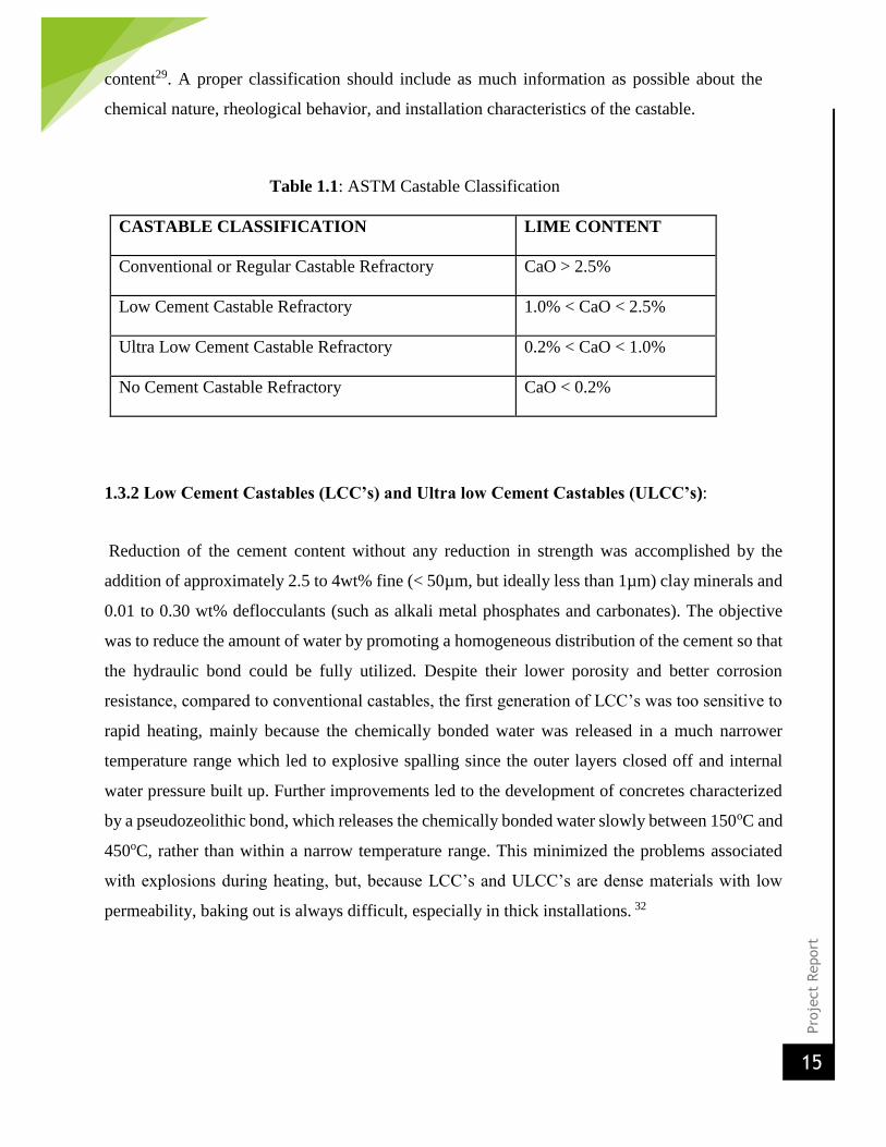
content29. A proper classification should include as much information as possible about the
chemical nature, rheological behavior, and installation characteristics of the castable.
Table 1.1: ASTM Castable Classification
CASTABLE CLASSIFICATION LIME CONTENT
Conventional or Regular Castable Refractory CaO > 2.5%
Low Cement Castable Refractory 1.0% < CaO < 2.5%
Ultra Low Cement Castable Refractory 0.2% < CaO < 1.0%
No Cement Castable Refractory CaO < 0.2%
1.3.2 Low Cement Castables (LCC’s) and Ultra low Cement Castables (ULCC’s):
Reduction of the cement content without any reduction in strength was accomplished by the
addition of approximately 2.5 to 4wt% fine (< 50µm, but ideally less than 1µm) clay minerals and
0.01 to 0.30 wt% deflocculants (such as alkali metal phosphates and carbonates). The objective
was to reduce the amount of water by promoting a homogeneous distribution of the cement so that
the hydraulic bond could be fully utilized. Despite their lower porosity and better corrosion
resistance, compared to conventional castables, the first generation of LCC’s was too sensitive to
rapid heating, mainly because the chemically bonded water was released in a much narrower
temperature range which led to explosive spalling since the outer layers closed off and internal
water pressure built up. Further improvements led to the development of concretes characterized
by a pseudozeolithic bond, which releases the chemically bonded water slowly between 150oC and
450oC, rather than within a narrow temperature range. This minimized the problems associated
with explosions during heating, but, because LCC’s and ULCC’s are dense materials with low
permeability, baking out is always difficult, especially in thick installations. 32
Pro
ject
Report
16
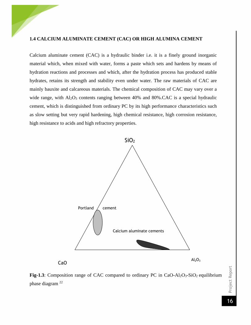
1.4 CALCIUM ALUMINATE CEMENT (CAC) OR HIGH ALUMINA CEMENT
Calcium aluminate cement (CAC) is a hydraulic binder i.e. it is a finely ground inorganic
material which, when mixed with water, forms a paste which sets and hardens by means of
hydration reactions and processes and which, after the hydration process has produced stable
hydrates, retains its strength and stability even under water. The raw materials of CAC are
mainly bauxite and calcareous materials. The chemical composition of CAC may vary over a
wide range, with Al2O3 contents ranging between 40% and 80%.CAC is a special hydraulic
cement, which is distinguished from ordinary PC by its high performance characteristics such
as slow setting but very rapid hardening, high chemical resistance, high corrosion resistance,
high resistance to acids and high refractory properties.
Fig-1.3: Composition range of CAC compared to ordinary PC in CaO-Al2O3-SiO2 equilibrium
phase diagram 22
SiO2
Portland cement
Calcium aluminate cements
Al2O3 CaO
Pro
ject
Report
17
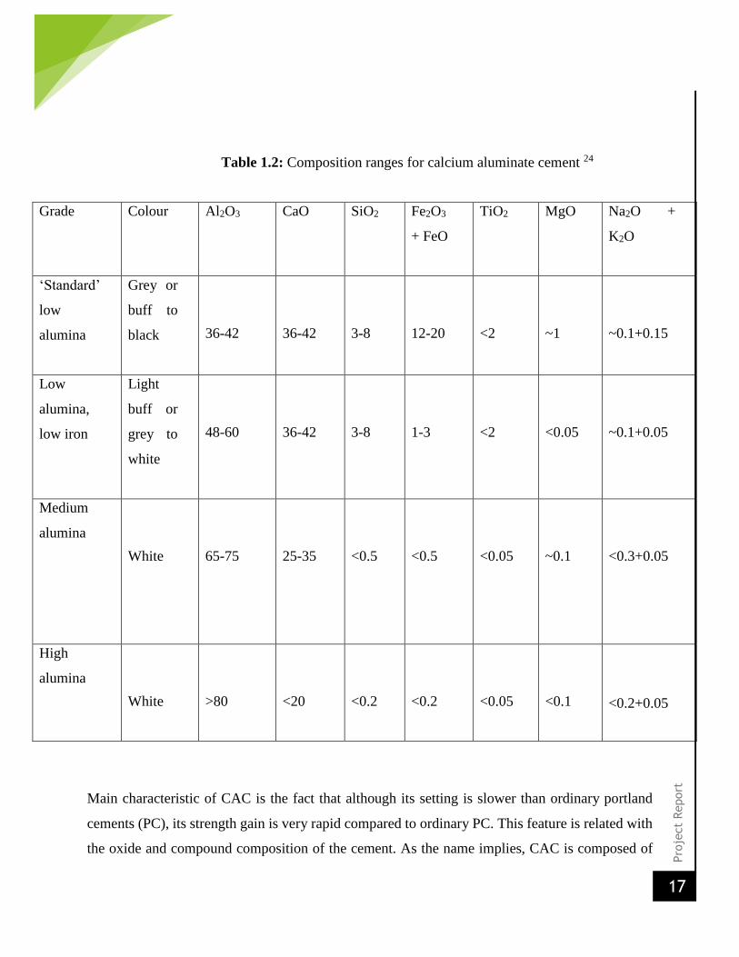
Table 1.2: Composition ranges for calcium aluminate cement 24
Grade Colour Al2O3 CaO SiO2 Fe2O3
+ FeO
TiO2 MgO Na2O +
K2O
‘Standard’
low
alumina
Grey or
buff to
black
36-42
36-42
3-8
12-20
<2
~1
~0.1+0.15
Low
alumina,
low iron
Light
buff or
grey to
white
48-60
36-42
3-8
1-3
<2
<0.05
~0.1+0.05
Medium
alumina
White
65-75
25-35
<0.5
<0.5
<0.05
~0.1
<0.3+0.05
High
alumina
White
>80
<20
<0.2
<0.2
<0.05
<0.1
<0.2+0.05
Main characteristic of CAC is the fact that although its setting is slower than ordinary portland
cements (PC), its strength gain is very rapid compared to ordinary PC. This feature is related with
the oxide and compound composition of the cement. As the name implies, CAC is composed of
Pro
ject
Report
18
mainly calcium aluminates and the main phase, mono calcium aluminate (CA), which is
responsible for the rapid hardening of the CAC, liberating huge amount of heat of hydration.
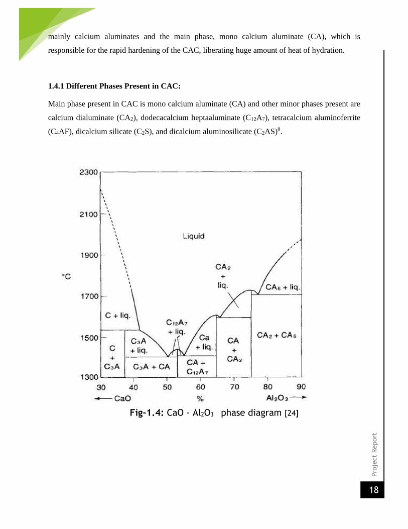
1.4.1 Different Phases Present in CAC:
Main phase present in CAC is mono calcium aluminate (CA) and other minor phases present are
calcium dialuminate (CA2), dodecacalcium heptaaluminate (C12A7), tetracalcium aluminoferrite
(C4AF), dicalcium silicate (C2S), and dicalcium aluminosilicate (C2AS)8.
Fig-1.4: CaO - Al2O3 phase diagram [24]
Pro
ject
Report
19
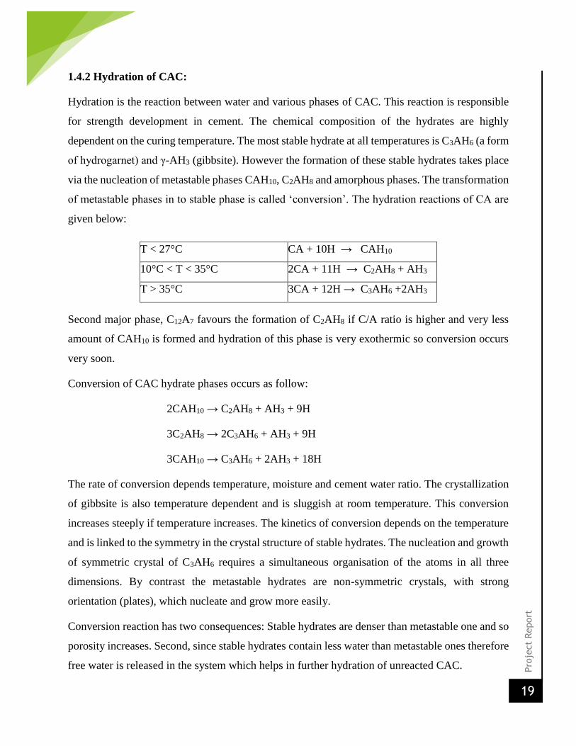
1.4.2 Hydration of CAC:
Hydration is the reaction between water and various phases of CAC. This reaction is responsible
for strength development in cement. The chemical composition of the hydrates are highly
dependent on the curing temperature. The most stable hydrate at all temperatures is C3AH6 (a form
of hydrogarnet) and γ-AH3 (gibbsite). However the formation of these stable hydrates takes place
via the nucleation of metastable phases CAH10, C2AH8 and amorphous phases. The transformation
of metastable phases in to stable phase is called ‘conversion’. The hydration reactions of CA are
given below:
Second major phase, C12A7 favours the formation of C2AH8 if C/A ratio is higher and very less
amount of CAH10 is formed and hydration of this phase is very exothermic so conversion occurs
very soon.
Conversion of CAC hydrate phases occurs as follow:
2CAH10 → C2AH8 + AH3 + 9H
3C2AH8 → 2C3AH6 + AH3 + 9H
3CAH10 → C3AH6 + 2AH3 + 18H
The rate of conversion depends temperature, moisture and cement water ratio. The crystallization
of gibbsite is also temperature dependent and is sluggish at room temperature. This conversion
increases steeply if temperature increases. The kinetics of conversion depends on the temperature
and is linked to the symmetry in the crystal structure of stable hydrates. The nucleation and growth
of symmetric crystal of C3AH6 requires a simultaneous organisation of the atoms in all three
dimensions. By contrast the metastable hydrates are non-symmetric crystals, with strong
orientation (plates), which nucleate and grow more easily.
Conversion reaction has two consequences: Stable hydrates are denser than metastable one and so
porosity increases. Second, since stable hydrates contain less water than metastable ones therefore
free water is released in the system which helps in further hydration of unreacted CAC.
T < 27°C CA + 10H → CAH10
10°C < T < 35°C 2CA + 11H → C2AH8 + AH3
T > 35°C 3CA + 12H → C3AH6 +2AH3

Pro
ject
Report
20
Table 1.3: Physical properties of hydrates of Calcium Aluminium Hydrates 23
Hydration
Products
Chemical
Composition (%)
Crystal Form Density
(g/cm3)
Volume Ratio
of Hydrates to
CA CaO Al2O3 H2O
CAH10 16.6 30.1 53.3 Metastable
hexagonal
prism(fine needles)
1.72 3.68
C2AH8 31.3 28.4 40.3 Metastable
hexagonal plates
1.95 2.33
C3AH6 44.4 27.0 28.6 Stable cubic
trapezohedrals
(angular grains)
2.52 1.75
AH3 - 65.4 34.8 Stable hexagonal
prism
2.42 -
1.4.3 Hydration mechanism of CAC:
The mechanism of hydration of CAC is generally accepted to be ‘through’ solution i.e. through
dissolution of anhydrous phases followed by precipitation of hydrate phases from solution. The
CAC dissolves as calcium ions (Ca2+) and aluminium hydroxide ions (Al(OH)-14) in the water and
the process continues till the saturation level is reached and also during this process pH of the
solution increases up to 12. When the concentration of calcium ions and aluminium hydroxide ions
reaches its solubility limit in water then nucleation and precipitation of calcium aluminium
hydrates crystal and gibbsite occurs 17,18. These hydrates starts precipitation on the neighboring
unreacted surface by forming a gel layer and this layer has been found to be permeable for the
water and so the reaction continues till the water is available for dissolution and hydration. The
time duration during which nucleation takes place is called nucleation period or induction period
(shown in Fig-1.9), during this period nuclei attain critical size and certain quantity. The induction
period continues till the precipitation of first hydrate crystal occurs 20. Since nucleation takes
place on the surface of unreacted particles i.e. heterogeneous nucleation so once critical size is

Pro
ject
Report
21
attained, nucleation period is followed by rapid growth and massive precipitation of hydrates
which reduces the concentration of solution.
Fig-1.6: Concentration variation of ions with time
Minerals (CA, C 12
A 7 ) dissolution in water
Ca 2+ + Al(OH) 4-
Oversaturation, pH rises up to 12
Precipitation of CAH 10
, C 2 AH
8 , C
3 AH
6 , and AH
3 crystals
Growth of crystals around cement grains (stiffening)
Bonding between cement grains (strength development)
Continuous
dissolution
and
precipitation
Fig-1.5: Summary of hydration mechanism of CAC [23]

Pro
ject
Report
22
1.5 Spinels
Spinels are double oxides that crystallize in the cubic crystallographic system. Spinels are
generally indicated by the formula AB2O4, where “A” is a divalent element such as Mg, Fe, Zn,
Mn, Ni, Co, V, and Cu, and “B” a trivalent element such as Al, Fe, and Cr. Some of the spinels
used as refractory are FeFe2O4, FeAl2O4, FeCr2O4, MgFe2O4, MgAl2O4, MgCr2O4, and their solid
solutions. MgAl2O4 and MgCr2O4 consist of good physical and chemical properties such as high
refractoriness, high mechanical strength, and high resistance to chemical attack and hence are used
extensively.16
1.5.1 Magnesia-Alumina Spinel (MgAl2O4)
Magnesium aluminate spinel (MgAl2O4) is an excellent refractory oxide of immense technological
importance as a structural ceramic. It possesses useful physical, chemical and thermal properties,
both at normal and elevated temperatures. It melts congruently at 2135°C, shows high resistance
to attack by most of the acids and alkalis and has low electrical losses. Due to these desirable
properties, it has a wide range of application in structural, chemical, optical and electrical industry.
It is used as a refractory in lining of steel-making furnaces, transition and burning zones of cement
rotary kilns, checker work of the glass furnace regenerators, sidewalls and bottom of the steel
ladles, glass furnaces and melting tanks. 16
1.5.1.1 Properties
Spinel synthesized using different raw materials and via different processes; varies in the
properties spinels vary. Spinel has a higher melting temperature (2150oC) than Al2O3 (2054oC) but
lower than MgO (2850oC). Its thermal expansion coefficient (~8.4×10⁻⁶/K) is close to that of
alumina (~8.8 × 10⁻⁶/K), but much lower than MgO (~13.5 ×10⁻⁶/K). It has superior hydration
resistance than periclase and thus can be used in water-based castable systems. Mg-Al spinel has
high corrosion resistance in Fe reach slag and alkalies.
Pro
ject
Report
23
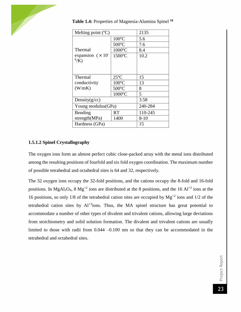
Table 1.4: Properties of Magnesia-Alumina Spinel 16
Melting point (oC) 2135
Thermal
expansion ( × 10-
6/K)
100oC 5.6
500oC 7.6
1000oC 8.4
1500oC 10.2
Thermal
conductivity
(W/mK)
25oC 15
100oC 13
500oC 8
1000oC 5
Density(g/cc) 3.58
Young modulus(GPa) 240-284
Bending
strength(MPa)
RT 110-245
1400 8-10
Hardness (GPa) 15
1.5.1.2 Spinel Crystallography
The oxygen ions form an almost perfect cubic close-packed array with the metal ions distributed
among the resulting positions of fourfold and six fold oxygen coordination. The maximum number
of possible tetrahedral and octahedral sites is 64 and 32, respectively.
The 32 oxygen ions occupy the 32-fold positions, and the cations occupy the 8-fold and 16-fold
positions. In MgAl2O4, 8 Mg+2 ions are distributed at the 8 positions, and the 16 Al+3 ions at the
16 positions, so only 1/8 of the tetrahedral cation sites are occupied by Mg+2 ions and 1/2 of the
tetrahedral cation sites by Al+3ions. Thus, the MA spinel structure has great potential to
accommodate a number of other types of divalent and trivalent cations, allowing large deviations
from stoichiometry and solid solution formation. The divalent and trivalent cations are usually
limited to those with radii from 0.044 –0.100 nm so that they can be accommodated in the
tetrahedral and octahedral sites.

Pro
ject
Report
24
Fig 1.7: A view of Spinel Crystal Structure 16

Pro
ject
Report
25
1.5.1.3 Composition
From Mg-Al phase diagram it is clear that Mg-Al has a range of stoichiometric field.
Stoichiometric Mg-Al consists of 28 wt% MgO and 72 wt% Al2O3. With increasing temperature,
a wide range of nonstoichiometric forms in the system and the solubility of alumina in Mg-Al
spinel is more than magnesia at the same temperature. Single-phase Mg-Al spinel is alumina-rich,
and this can be indicated by the notation MgO.nAl2O3 where m, the number of moles of alumina,
can be as high as 7.3. MgO-rich spinel (n<1) is, according to the phase diagram, theoretically
achievable by quenching from very high temperatures (>1600oC), but more commonly MgO-rich
spinel grain contains periclase and is located in the MgO-spinel binary phase field. 16
Fig 1.8: Phase diagram of the MgO–Al2O3 system 16
The excess doping of Al+3 ions leads to formation of cation deficiency in the structure and so the
spinel lattice constant decrease with increase in the mol % of the alumina. Doping with excess
MgO causes the anion deficiency in the structure and in this case the lattice constant increases with
MgO content.

Pro
ject
Report
26
1.5.1.4 Alumina-rich spinels
Alumina-rich spinels are the largest volume of the refractory spinels, as they are used as
components of refractories for steel production. Their use is driven by two main sets of properties;
thermal characteristics, such as improvements to hot strength and to thermal shock resistance; and
resistance to corrosion by steel-making slag. Additions of high purity alumina rich spinels to
alumina castables remarkably improve the hot strength. Spinel content of 15-30 mass %, which
corresponds to MgO content of 4-10 mass% is commonly used. Recent developments in the use
of fired spinel refractories, e.g., in steel ladles, have indicated up to a 60% reduction in lifetime
when comparing low-silica (<0.1% SiO2) to high silica (1.0% SiO2) spinel brick. This
demonstrated that optimal performance can only be expected from high purity synthetic materials.
For a spinel that is more alumina-rich, such as AR 90, the Al2O3 rich spinel solid solution becomes
thermodynamically instable at the steel making temperatures and alumina is released from the
spinel. The alumina reacts with CaO from the slag to form an inter-granular phase, calcium
hexaluminate (CA6). CA6 is a very refractory phase (onset of melting at 1875°C), and in addition
the reaction exhibits a volume expansion, causing a reduction in refractory surface porosity and
reducing the tendency for slag penetration. 34
1.6 Tabular Alumina
Tabular alumina is prepared by pressing the calcined alumina obtained from Bayer’s process into
a ‘ball’ like shape. Then it is sintered at very high temperatures of 1800-1900 degrees Celsius. The
resultant product is called tabular alumina. The name ‘tabular’ arises due to the fact that it is formed
in large ‘tablet’ like structures. This alignment of the tabular alumina crystals provides a large
strength to it. This material has excellent mechanical strength and abrasion resistance. Due to its
manufacturing process, tabular alumina is a very costly material.
1.6.1 Properties of tabular alumina:
Highly dense refractory material. Tabular alumina is a well sintered crystalline alpha
alumina which is used both as a refractory aggregate and as a matrix.

Pro
ject
Report
27
Tabular alumina is a kind of pure sintered corundum, which is sintered and completely
shrinks without adding any additive, such as MgO or B2O3, with coarse crystals and well-
developed α- Al2O3 crystal structure.
The tabular crystal structure is characterized by narrow pores, with more closed porosity,
high purity, good stability, volume density and tiny re-firing shrinkage.
It has a high thermal shock resistance, high wear resistance, and a high chemical resistance
as well.
1.7 Fused Magnesia
Magnesite (magnesium carbonate MgCO3) is converted into magnesia by the application of heat
which drives off carbon dioxide (CO2), thereby converting the carbonate to the oxide of
magnesium (MgO). Fused magnesia is produced in a three phase electric arc furnace. Taking high
grade magnesite or calcined magnesia as raw materials, 12 hours is required for the fusion process
at temperatures in excess of 2750°C. The process promotes the growth of very large crystals of
periclase (>1000 microns compared with 50-100 microns for dead burned magnesia) with a density
approaching the theoretical maximum of 3.58g/cm3. 26
In fused magnesia production, the main constraints on capacity are the size and number of electric
arc furnaces, and the cost of energy. The manufacture of fused magnesia is very power intensive
with electricity consumption varying between 3500-4500 kWh/tonne; fused magnesia producers
often quote total capacity based on utilising off peak power.
The addition of fused magnesia grains can greatly enhance the performance and durability of basic
refractories such as magcarbon bricks. This is a function of a higher bulk specific gravity and large
periclase crystal size, plus realignment of accessory silicates. Refractory grade fused magnesia has
exacting specifications and is normally characterised by the following:
• Generally high magnesia content (minimum 96 per cent MgO and up to/exceeding 99% MgO)
• Low silica; lime:silica ratios of 2:1
• Densities of 3.50 g/cm3 or more
• Large periclase crystal sizes (>1000 microns)
Due to its excellent corrosion resistance, refractory grade fused magnesia is used in high wear
areas in steel making, eg, basic oxygen and electric arc furnaces, converters and ladles. Ultra high

Pro
ject
Report
28
purity (>99 per cent MgO) grades have been used in high-tech applications such as optical
equipment, nuclear reactors and rocket nozzles.
1.8 Use of Additives
1.8.1 Darvan C
The dispersion of powders in liquid is an important process in the ceramic industry. The good
dispersion of particles with high solids loading is often a prerequisite to obtain optimum packing
state (high green density), which in turn influences the sinterability and the physical as well as
chemical properties of the final product. DARVAN C, an ammonium polymethacrylate, is one
such dispersant which helps in monitoring of the state of dispersion/aggregation.
1.8.1.1 Physical Properties: 35
Molecular Weight: 10,000 to 16,000
Appearance: Clear to slightly opalescent amber fluid
Density at 25°C: 1.11 ± 0.02 Mg/m3
Weight per gallon: 9.2 to 9.2 lb
Percent solids: 25.0 ± 1.0%
Percent ash: 0.04% maximum – on wet weight
pH: 7.5 to 9.0
Viscosity at 25°C: 75 cps (maximum)
Solubility: Completely soluble in water systems.
Stability: Stable in the presence of alkalies over a wide pH range.
Burn out: DARVAN C-N begins to burn out at 450°F
(232°C)
Storage: Freezes at -5°C. Protection from freezing needed.

Pro
ject
Report
29
1.8.2 Citric Acid
Citric Acid is a weak organic acid with the formula C₆H₈O₇. It has been seen that 0.1% citric acid
accelerates whereas too high dose (>0.1%) of citric acid retards the hydration of cement.
1.8.1.2 Properties35
Molecular formula C6H8O7
Molar mass 192.124 g/mol (anhydrous)
210.14 g/mol (monohydrate)
Appearance crystalline white solid
Odor odorless
Density 1.665 g/cm3(1.5g/cm3 for monohydrate)
Melting point 156 °C (313 °F; 429 K)
Boiling point 310 °C (590 °F; 583 K) (decomposes)
Solubility in water 59 g/100 ml (20 °C)
Solubility very soluble in ethanol
soluble in ether, ethyl acetate
insoluble in benzene,chloroform
log P -1.64
Acidity (pKa) pKa1 = 3.14
pKa2 = 4.75
pKa3 = 6.39,6.40

Pro
ject
Report
30
CHAPTER 2
EXPERIMENTAL PROCEDURE

Pro
ject
Report
31
2.1 Raw Material Collection
Tabular Alumina and Calcium Aluminate Cement (CA14M and CA25R) were collected from
Almatis Company. The grades of Tabular Alumina which were used in the project are 3-6 mm, 1-
3 mm, 0.5-1 mm, 0.2-0.5 mm, 0.045-0.2 mm and 0.01-0.045 mm. Reactive Alumina was used as
an accelerator and had a grade of 0.0025-0.01 mm. Fused Magnesia (0.01-0.045 mm) was used in
the in-situ method composition, whereas, Magnesia-Alumina spinel (AR-78), also collected from
Almatis, was used for the direct addition route. The grade used was 0.5-1 mm.
2.2 Casting and Sample Preparation
The batches were prepared according to the proportion of the composition given in Table 1 below.
The modified Andreason’s equation was used to determine the compositions. The ‘q’ value was
kept 0.29.
Modified Andreason’s Equation:
CPFT = (dxq – dmin
q)/(dmaxq – dmin
q)
where, dx = size of particle in the fraction, dmax = maximum particle size in the batch, dmin =
minimum particle size in the batch
The mixing was done in a Hobart Mixer for 15-20 minutes, until a visibly homogenous batch was
prepared. During batching the required amount of water was added to the batch and then it was
thoroughly mixed. The batch was casted in 50mm X 50mm X 50mm cubic steel molds.
Fig-2.1: Casting in steel moulds

Pro
ject
Report
32
Table 2.1: Batch Compositions
CA25R (1) CA14M (1) CA25R (2) CA14M (2)
Tabular Alumina
3-6 20.34% 20.34% 20.34% 20.34%
1-3 24.92% 24.92% 24.92% 24.92%
0.5-1 12.1% 12.1% 2.1% 2.1%
0.2-0.5 12.68% 12.68% 12.68% 12.68%
0.045-0.2 10.62% 10.62% 10.62% 10.62%
0.01-0.045 1.76% 1.76% 4.56% 4.56%
Fume Silica 5% 5% 5% 5%
Reactive Alumina 5.78% 5.78% 5.78% 5.78%
CAC (CA25R) 4% 4%
CAC (CA14M) 4% 4% MgO 2.8% 2.8%
Spinel (AR-78) 10% 10%
5% (approx.) water was added in each batch containing magnesia, while around 4% (approx.)
water was added in each spinel containing batch.
The molds, once casted, were covered with a wet cloth to keep the temperature under control. The
molds were left untouched as such for 24 hours and then demolding was done. The blocks formed
were then kept open for another 24 hours for air drying and then dried at 110oC in an oven.
Pro
ject
Report
33
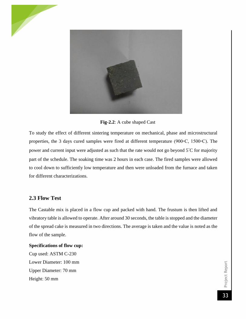
Fig-2.2: A cube shaped Cast
To study the effect of different sintering temperature on mechanical, phase and microstructural
properties, the 3 days cured samples were fired at different temperature (900◦C, 1500◦C). The
power and current input were adjusted as such that the rate would not go beyond 5◦C for majority
part of the schedule. The soaking time was 2 hours in each case. The fired samples were allowed
to cool down to sufficiently low temperature and then were unloaded from the furnace and taken
for different characterizations.
2.3 Flow Test
The Castable mix is placed in a flow cup and packed with hand. The frustum is then lifted and
vibratory table is allowed to operate. After around 30 seconds, the table is stopped and the diameter
of the spread cake is measured in two directions. The average is taken and the value is noted as the
flow of the sample.
Specifications of flow cup:
Cup used: ASTM C-230
Lower Diameter: 100 mm
Upper Diameter: 70 mm
Height: 50 mm
Pro
ject
Report
34
2.4 Determination of Density Variation
The dimensions and weights of each of the 110oC dried as well as the fired samples are measured
and the dimensional density is calculated. Also, the volume expansion of each sample is measured.
All these results are then properly tabulated.
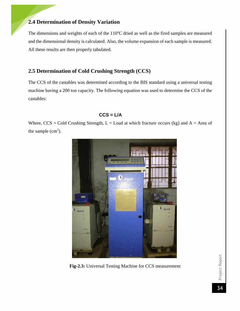
2.5 Determination of Cold Crushing Strength (CCS)
The CCS of the castables was determined according to the BIS standard using a universal testing
machine having a 200 ton capacity. The following equation was used to determine the CCS of the
castables:
CCS = L/A
Where, CCS = Cold Crushing Strength, L = Load at which fracture occurs (kg) and A = Area of
the sample (cm2).
Fig-2.3: Universal Testing Machine for CCS measurement

Pro
ject
Report
35
2.6 Phase Analysis by XRD
The X-ray diffraction method was used to determine the present phases in the fired castables. The
main aim was to observe whether spinel was formed or not in the MgO containing samples. XRD
measurements were performed at a 3oC/min scan rate using a Philips Advance D8 X-ray
diffractometer operated at 40 keV and 30 mA and in the 2 theta range of 10o to 80o.
The samples were crushed to powder and collected and then sent for X-ray analysis. The fining of
the particle size was done to expose more number of atoms to the incoming X rays so that a
sufficient intensity could be obtained after diffraction. The X-ray analysis data was matched with
the standard JCPDS software to identify the phases.
Fig-2.4: XRD Machine

Pro
ject
Report
36
CHAPTER 3
RESULTS AND DISCUSSIONS

Pro
ject
Report
37
3.1 Chemical Analysis of Raw Materials7:
The following are the chemical compositions of the major raw materials used:
Tabular Alumina7:
1. Al2O3 99.5%
2. SiO2 <0.09%
3. Na2O <0.4%
Calcium Aluminate Cement:
CA-14M:
1. Al2O3: 71%
2. CaO: 28%
3. Na2O: 0.3%
4. SiO2: 0.3%
5. MgO: 0.4%
CA-25R:
1. Al2O3: 78%
2. CaO: 19%
3. Na2O: 0.6%
4. SiO2: 0.3%
5. Fe2O3: 0.2%
6. MgO: 0.4%
Spinel:
AR-78:
1. MgO: 24%
2. Al2O3: 74%
3. CaO: 0.24%
4. SiO2: 0.10%
5. Na2O: 0.09%
6. Fe2O3: 0.15%

Pro
ject
Report
38
3.2 Flow Behavior Analysis:
Table 3.1: Flow Results
Sample Flow
CA-25R(1) 160mm
CA-14M(1) 150mm
CA-25R(2) 170mm
CA-14M(2) 165mm
The flow in each of the batch, as can be seen from the table above, varies between 160-175mm.
The flow behavior was enhanced by the use of Fume Silica. It is important in case of a Castable to
have a good flow characteristic so that it can spread properly while application on site. It was seen
that the batches containing magnesia absorbed more water than those containing spinel. This was
mainly due to the fine size of magnesia particles. But, the flow more or less has remained the same.
3.3 Density Variation:
3.18
2.82
3.01
3.25
2.97
3.08
2.6
2.7
2.8
2.9
3
3.1
3.2
3.3
110 900 1500
Densi
ty (
g/cc)
Temperature (oC)
Density Variation of CA-25R Samples
In-situ Preformed
Pro
ject
Report
39
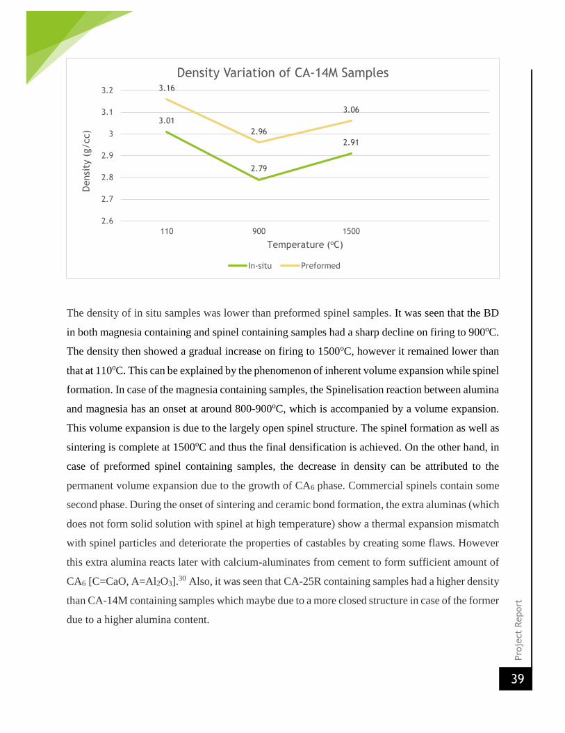
The density of in situ samples was lower than preformed spinel samples. It was seen that the BD
in both magnesia containing and spinel containing samples had a sharp decline on firing to 900oC.
The density then showed a gradual increase on firing to 1500oC, however it remained lower than
that at 110oC. This can be explained by the phenomenon of inherent volume expansion while spinel
formation. In case of the magnesia containing samples, the Spinelisation reaction between alumina
and magnesia has an onset at around 800-900oC, which is accompanied by a volume expansion.
This volume expansion is due to the largely open spinel structure. The spinel formation as well as
sintering is complete at 1500oC and thus the final densification is achieved. On the other hand, in
case of preformed spinel containing samples, the decrease in density can be attributed to the
permanent volume expansion due to the growth of CA6 phase. Commercial spinels contain some
second phase. During the onset of sintering and ceramic bond formation, the extra aluminas (which
does not form solid solution with spinel at high temperature) show a thermal expansion mismatch
with spinel particles and deteriorate the properties of castables by creating some flaws. However
this extra alumina reacts later with calcium-aluminates from cement to form sufficient amount of
CA6 [C=CaO, A=Al2O3].30 Also, it was seen that CA-25R containing samples had a higher density
than CA-14M containing samples which maybe due to a more closed structure in case of the former
due to a higher alumina content.
3.01
2.79
2.91
3.16
2.96
3.06
2.6
2.7
2.8
2.9
3
3.1
3.2
110 900 1500
Densi
ty (
g/cc)
Temperature (oC)
Density Variation of CA-14M Samples
In-situ Preformed
Pro
ject
Report
40
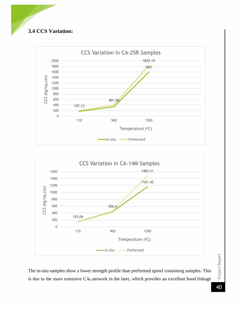
3.4 CCS Variation:
The in-situ samples show a lower strength profile than preformed spinel containing samples. This
is due to the more extensive CA6 network in the later, which provides an excellent bond linkage
1601
197.13
401.06
1835.19
0
200
400
600
800
1000
1200
1400
1600
1800
2000
110 900 1500
CCS (
kg/sq
.cm
)
Temperature (oC)
CCS Variation in CA-25R Samples
In-situ Preformed
1161.42
155.04
456.4
1483.21
0
200
400
600
800
1000
1200
1400
1600
110 900 1500
CCS (
kg/sq
.cm
)
Temperature (oC)
CCS Variation in CA-14M Samples
In-situ Preformed

Pro
ject
Report
41
between grains in the matrix by an inter-locking morphology.30 Also, in case of in-situ
Spinelisation, there is a higher and a more abrupt volume expansion, thus lowering strength and
causing an increased chance of failure. It is also seen that the high temperature strength of CA-
25R containing samples is much more than CA-14M containing samples. This can be because of
a lower CaO composition and a higher Al2O3 content in CA-25R. CaO can form low melting
phases at high temperatures and thus lower the strength.
3.5 XRD Analysis
The XRD pattern of fired in-situ Spinelisation samples was carried out. The following plots
were obtained.
0 10 20 30 40 50 60 70 80 90
-50
0
50
100
150
200
250
300
350
#
*
*#
@
@
@
@
@ *
*
*
*
*
#
*
Inte
nsi
ty
2 (degree)
@- Spinel
# - MgO
* - Al2O3
*
@
Fig 3.1: XRD of 900oC fired CA-14M(1)

Pro
ject
Report
42
0 10 20 30 40 50 60 70 80 90
0
100
200
300
400
@
2 (degree)
@- Spinel
# - MgO
* - Al2O3
#
#
#
@@@@
** *
*
**
Inte
nsi
ty
*
@
#
Fig 3.2: XRD of 900oC fired CA-25R(1)
0 10 20 30 40 50 60 70 80 90
0
50
100
150
200
250
300@- Spinel
# - MgO
* - Al2O3
#
##
#*
**
*
***
@ @
@
@
@
@
@Inte
nsi
ty
2 (degree)
@
*
#
Fig 3.3: XRD of 1500oC fired CA-14M(1)

Pro
ject
Report
43
It was seen that in the 900oC fired samples, there were a large number of alumina peaks having
high intensities. There were a few, large magnesia peaks as well. The MgAl2O4 spinel peaks are
small. This corroborates the theoretical finding from the literature that at this temperature range
the spinel formation starts and there is a large amount of magnesia present which show
considerably large peaks. On the other hand, the 1500oC fired sample has large spinel peaks. This
is because of the completion of Spinelisation reaction. A few small magnesia peaks show the
presence of unreacted magnesia at the said temperature.

Pro
ject
Report
44
CHAPTER 4
SUMMARY
Pro
ject
Report
45
Both In-situ Spinelisation and preformed spinel addition methods are widely popular.
Preformed spinel addition is expensive, hence there is a need to study and develop the in-
situ method to increase its feasibility.
In-situ spinelisation’s biggest disadvantage is the abrupt volume expansion during spinel
formation, which can lead to failure of the Castable.
Preformed spinel addition method leads to a better strength and density profile. In-situ
method can thus be applied accordingly to optimize the net cost.
There is a density drop in each case at T~900oC.
The effect of cement can be seen in case of high temperature application. CA-25R
containing castables have a significantly higher strength at T~1500oC than CA-14M. This
is due to a higher CaO and a lower Al2O3 content in case of CA-14M.
Pro
ject
Report
46
References:
1. Weiping Ma and Paul W. Brown, Materials Research Laboratory, The Pennsylvania
State University: ‘Mechanisms of Reaction of Hydratable Aluminas’, J. Am. Ceram.
Soc.(1999), p-1,3
2. Raymond P. Racher, Leetsdale/USA; Rainer Kockegey-Lorenz, Gunter Büchel, Andreas
Buhr, Dagmar Gierisch, Almatis GmbH, Frankfurt and Ludwigshafen: ‘Improvements In
Workability Behavior Of Calcia-Free Hydratable Alumina Binders’, p-1-4
3. GUOTIAN YE, TOM TROCZYNSKI, Department of Materials Engineering, University of
British Columbia:’ Effect of magnesia on strength of hydratable alumina-bonded castable
refractories’, JOURNAL OF MATERIALS SCIENCE 40 (2005), p-1,3,4,5
4. N. Tzanova, S. Djambazov, P. Mitsev, University of Chemical Technology and
Metallurgy, Bulgaria: ‘CASTABLES IN Si3N4-Al2O3 SYSTEM’, Journal of Chemical
Technology and Metallurgy, 48, 2, 2013, p-1-3
5. Gre´gory Lefe`vre, Myriam Duc, Patrick Lepeut, Renaud Caplain,and Michel Fe´doroff:
‘Hydration of ç-Alumina in Water and Its Effects on Surface Reactivity’, Langmuir 2002,
18, p-1,3,4
6. R. Saloma˜o, V.C. Pandolfelli: ‘The role of hydraulic binders on magnesia containing
refractory castables: Calcium aluminate cement and hydratable alumina’, Ceramics
International 35 (2009), p- 1.2.4
7. www. almatis.com
8. ASTM Volume 15.01 Refractories; Activated Carbon, Advanced Ceramics
9. Charles A.Schacht: ‘Refractories handbook’, p- 5-7
10. A. Bhatia, B.E.: ‘Overview of Refractory Materials’, p- 10-12

Pro
ject
Report
47
11. ‘Alumina (Aluminium Oxide) – The Different Types of Commercially Available
Grades’, The A to Z of Materials. Archived from the original on 10 October 2007.
12. Material Properties Data: Alumina (Aluminum Oxide)
13. "Aloxite". ChemIndustry.com database. Retrieved 24 February 2007‖
14. Yu. E. Pivinskii, Pav. V. Dyakin and P. V. Dyakin: ‘DISPERSING
(DEFLOCCULATING) ALUMINAS’, Refractories and Industrial Ceramics, Vol. 45,
No. 3, 2004, p- 1
15. Charles A.Schacht: ‘Refractories handbook’, p- 8
16. Charles A.Schacht: ‘Refractories handbook’, p- 83-86, 215-257
17. Christopher PARR, Christoph WOHRMEYER, Benoit VALDELIEVRE and Akihiko
NAMBA “Effect of formulation parameters upon the strength development of calcium
aluminate cement containing castables” presente at the TRAJ Refractory Conference,
Osaka, Japan, 2002
18. Rettel, A., Gessner, W., Mueller D. and Scheler, G., On the Hydration of Calcium
Aluminates (Ca Al2O4) at Various Temperatures, Trans. Brit. Ceram. Soc., 84 (1), 25
(1985).
19. Gessner, W., Rettel, A., Mueller, D. and Oliew, G. “Time Course of Hydration of
Calcium Aluminate (CaO. Al2O3) with Linearly Increasing Temperature”,
Silikattechnik, 36 (7), 197 (1985).
20. I.R.Oliveria, F.S.Ortega, V.C. Pandolfelli “Hydration of CAC in castable refractory matrix
containing processing additives”, Ceramic international 35(2009) 1545-1552.
21. Kirca,O.,Sahin, M., “Kalsiyum Aluminati Cimentolarm Refrakterlik Ozellikeri” 12.
Ulusalarasi Metalurgi-Malzeme Kongresi Bildiriler Kitabi, 28 september-02 october 2005.
22. Kirca,O.,Sahin, M., Erdem T.K. “Corrosion resistance of white Portland cement:The
effects pozzolanic admixtures”,Proceedings of 9th International Corrosion Symposium, pp.
432-440, Ankara, 22-24 september 2004.

Pro
ject
Report
48
23. Kirca,O.,Sahin, M., Erdem T.K. “An experimental study on the construction materials of
the Ankara Citadel”, ProceedingS of 4th International Seminar on Structural Analysis of
Historical Constructions. Vol.1,pp.223-229, Padova-Italy, 10-13 nov 2004
24. “Lea’s Chemistry of Cement and Concrete” by Peter Hewlett,ISBN:0750662565,
Publisher Elsevier Science & technology Books, page no-717-720
25. S N Laha, “Non recovery coke ovens – An overview and an innovative Indian refractories
experience’, VOL. 9, NO. 1 February 2006, IIM Metal news
26. ‘Magnesia - Forms, Applications and Production Processes’; William Hughes, NSW
Department of Mineral Resources
27. J. Yamada, S. Sakaki, K. Kasai, H. Ishimatsu,”Application technology of monolithic
refractories in NSC: Proceedings of the Unified Int. Tech. conf. on ‘Refractories’,
UNITECR ‘ 95 (Kyoto, Japan,1995),pp. 277-84
28. Refractories production and properties, J.H. Chesters, The Iron and steel institute, London,
Carlton house Terrace, p.99-100
29. A. Nishikawa,” technology of monolithic refractories”,Pilbrico japan Co. Ltd, Tokyo,
Japan ,1984
30. ‘Effect of preformed and in situ spinels on microstructure and properties of a low cement
refractory castable’, Ceramics International 30 (2004) 369–380, S. Mukhopadhyaya, P.K.
Das Poddar, Department of Chemical Technology, Calcutta University
31. Li Zaigeng, G.Ye, P.R. China, Bonding and recent progress of monolithic refractories,
interceram , Vol 41 No. 3 1992
32. Dr. Bernard Clavaud (head R&D Lafarge monolithics refractories) Ing. Gerry
Landman(Product & application Engineer, Lafarge monolithics refractories) , Low and
Ultralow refractory castable for steelmaking
33. “Lea’s Chemistry of Cement and Concrete” by Peter Hewlett,ISBN:0750662565,
Publisher Elsevier Science & technology Books, page no-726
34. “Magnesium Aluminate Spinel Raw Materials for High Performance
Refractories for Steel Ladles”; Raymond P. Racher, Robert W. McConnell, Andreas
Buhr, Almatis Inc
35. www.rtvanderbilt.com