a comparative analysis of natural convection between
TRANSCRIPT
Abstract— The Natural convection heat transfer is often
augmented by the provision of rectangular fins on vertical or
horizontal surfaces in numerous electronic applications,
transformers, and motors. The recent trend in the electronic
industry is miniaturization, overcoming from overheat issue of
component due to reduction in surface area offered for heat
dissipation in such way that effective thermal management can
be attained. Therefore heat transfer from fin arrays has been
examined extensively, both experimentally and analytically.
A heat sink helps keep a device at a temperature below its
specified maximum operating temperature This work is
concerned with the comparative natural convective heat
transfer analysis of a Vertical and horizontal heats sink with
different number of fins and Fin spacing in which convective
heat transfer has been examined and with the help of thermo
physical characteristic performance is predicted by using Finite
element volume tool ANSYS - Fluent, where simulation is being
done. The goal is to carry out evaluating heat transfer within
the heat sink using different Density based module such as
incompressible and Boussinesq model. The FEV results are
validated with well published results in the literature and
furthermore with experimentation. The present Finite Element
Volume (FEV) and computational results show good
agreement.
Key Words: Tap Hole, CFD, Heat Transfer, FEV.
I. INTRODUCTION
In the present era, the trend to design electronic
products becomes thinner, lighter, shorter, & smaller. Due to
the actuality that shrinking in the dimension of these
electronic components will consequence in a drastic increase
in the heat generation rate when evaluating with previous
products. For this reason, an efficient cooling system to
remove the high heat generation and consequently maintains
the reliability and stability of the products, have gained
much attention.
The heat sink component is the most common heat
exchanger for CPUs and has been extensively exercised in
order to provide cooling utility for electronic components.
The conventional heat sink module utilized the natural as
well as forced convection cooling technique; dissipate
heat from CPUs to the ambient air. The combination of the
heat sink and fan design usually involved in this forced
convection cooling technique.
II. LITERATURE SURVEY
C.J. Kobus, T. Oshio 2005 investigate the effect of
thermal radiation on the thermal performance of heat sink
having pin fin array by theoretical and experimental
approach. In order to investigate the ability of influence of
thermal radiation on the thermal performance a new
coefficient effective radiation heat transfer is collaborated.
For validation of theoretical model it is matched with
experimental data.
Hung-Yi Li et al. 2007 done their investigation on plate-
fin heat sinks numerically and experimentally. Impingement
cooling is used by amending, the Reynolds number (Re), the
impingement distance (Y/D), and the fin dimensions. The
results shows that heat transfer is enhance by the heat sink
with increasing the impinging Reynolds number
G. Hetsroni et al. 2008, Natural convection heat transfer
in metal foam strips with two porosities examined
experimentally. Image processing of the thermal maps were
used for evaluation of non-equilibrium temperature
distribution for surface along with inner area of the metal
foam. Augmentation in heat transfer at natural convection
was found 18–20 times with respect to the flat plate.
Goshayeshi and Ampofo 2009 conduct numerical studies
on vertical fins, attached with the surface. Natural
convective heat transfer find out from heated plane, which is
kept into air with horizontal and vertical surface. Results
show that vertical plate with dimensionless form delivers
best performance for the natural cooling.
Dong-Kwon Kimet al. (2009) compared the thermal
performances of two types of heat sinks i.e.: plate-fin and
the second is pin-fin. By their investigation results propose,
a volume averaging approach based model for envisaging
the pressure drop and the thermal resistance.
A Comparative Analysis of
Natural Convection between Horizontal and
Vertical Heat Sink using CFD
Devanshu Prasad
Assistant Professor
Mechanical Engineering Department
Shri Shankaracharya Technical Campus, SSGI
Bhilai, C.G., India
Sumit Sharma
(M E Student)
Mechanical Engineering Department
Shri Shankaracharya Technical Campus, SSGI
Bhilai, C.G., India
International Journal of Engineering Research & Technology (IJERT)
ISSN: 2278-0181
www.ijert.orgIJERTV4IS061022
(This work is licensed under a Creative Commons Attribution 4.0 International License.)
Vol. 4 Issue 06, June-2015
1089
Burak and Hafit 2009 developed expression for prediction
of the optimal fin spacing for vertical rectangular fins with
rectangular base. The correlation for predicted on the basis
of experimental data.
Li and Chao 2009 investigated the performance of plate-
fin heat sinks with cross flow. The effect of different
parameters like the fin width, fin height, Re. number of
cooling air on the thermal resistance and the pressure drop of
heat sinks were studied.
Naidu et al.2010 investigates by both experimentally and
theoretically to find the outcome of inclination of the base of
the fin array on heat transfer rate.
Sable et al. 2010 investigated the natural convection of a
vertical heated plate with a multiple v- type fins having
ambient air surrounding. The mica gladded Nichrome
element is inserted between two base plates.
Mahmoud et al. 2011 conducted an experiment to
investigate the effects of micro fin height and spacing on
heat transfer coefficient for a horizontally mounted heat sink
under steady state natural convection conditions, fin height
ranging from 0.25-1.0 mm and fin spacing from 0.5 to 1.0
mm was taken.
Cheng-Hung al. 2011 developed a three-dimensional heat
sink design to estimate the optimum design variables.
Levenberg–Marquardt Method (LMM) was used and
commercial code CFD-ACE+ was developed. Temperature
distributions are dignified by using thermal camera for the
optimal heat sink modules and results are compared with the
numerical solutions to validate the design
Fahiminia et al. 2011investigated the laminar natural
convection on vertical surfaces computationally. The CFD
simulations are carried out using fluent software. Governing
equations are solved using a finite volume approach.
Relation between the velocity and pressure is made with
SIMPLE algorithm
Ayla dogan et al. 2012 performed numerical investigation
to find out the natural convection heat transfer from an
annular fin on a horizontal cylinder and present correlation
for the optimum fin spacing depending on Rayleigh number
and fin diameter.
Mateusz al.2013 used water and copper oxide nano fluids
for cooling heat sink of PC Processor. The commercial
package ANSYS Fluent 13 was employed to generate a CFD
heat transfer simulation. The experimental results were used
to validate the numerical model of the analyzed system.
Farhad et al.2013 solved .Navier–Stokes equations and
RNG based k- turbulent model for array of solid and
perforated fins mounted in vertical flat plates used to predict
turbulent flow parameters. Flow and heat transfer features
are presented for Re. no. from 2×10⁴ - 3.9 × 10⁴.Prandtl
numbers was taken as 0.71. Numerical simulation is
validated by compare with experimental results.
Qarnia and Lakhal 2013 using numercail approach
investigate the heat transfer by natural convection during the
melting of a phase change material. A mathematical model
was developed to investigate the thermal performance of
PCM based-heat sink.
Mehran al. 2014 examined numerically and
experimentally, Steady-state external natural convection heat
transfer from vertically-mounted rectangular interrupted
fins. FLUENT software is employed to develop a 2-D
numerical model of fin interruption effects. An experimental
numerical parametric study was performed to investigate the
effects of fin spacing, and fin disruption. A new compact
correlation is proposed for calculating the optimum
interruption length.
Emrana and Islama 2014 performed a three-dimensional
numerical simulation is in order to investigate the flow
dynamics and heat transfer characteristics in a microchannel
heat sink. A commercial CFD code was employing with finite element method to numerical simulation. For the
accuracy of results Mesh independence test was performed.
Younghwan and Kim 2015 investigated analytically
thermal performance of optimized plate-fin and pin-fin heat
sinks with a vertically oriented base plate. A new correlation
of the heat transfer coefficient is proposed and validated
experimentally to optimize pin-fin heat sinks.
III. MATHEMATICAL MODELLING
The governing equations for heat sink problem are
Navier-Stokes along with the energy equation. The Navier-
Stokes equation is applied to incompressible flows and
Newtonian fluids, including the continuity equation and the
equations of conservation of momentum on the x and y
According to equations
2 1 11 2
1 2
2 2
1 1
2 2
2 1 2
1( )
u u uu u
t x x
u ug T T
x x x
1
* *
2
* *
1 2
0u u
x x
x1 momentum equation
1
* * * * *
* *1 1 1 1 1
1 2* * * * *
1 2 1 2
*Pr
*
u u u u upu u
t x x x x x
x2 momentum equation
1
2
** * * *
* *2 2 2 2
1 2* * * * *
1 2 1 2
2
*Pr
*
Pr *
uu u u upu u
t x x x x x
Gr T
Energy equation
International Journal of Engineering Research & Technology (IJERT)
ISSN: 2278-0181
www.ijert.orgIJERTV4IS061022
(This work is licensed under a Creative Commons Attribution 4.0 International License.)
Vol. 4 Issue 06, June-2015
1090
* * * 2 * 2 ** *
1 2* * *2 *2
1 2 1 2*
T T T T Tu u
t x x x x
Where Gr is the Grashof number given as 3
2
g TLGr
Often, another non-dimensional number called the
Rayleigh number is used in the calculations. This is given as 3
Prg TL
Ra Gr
hl
Nuk
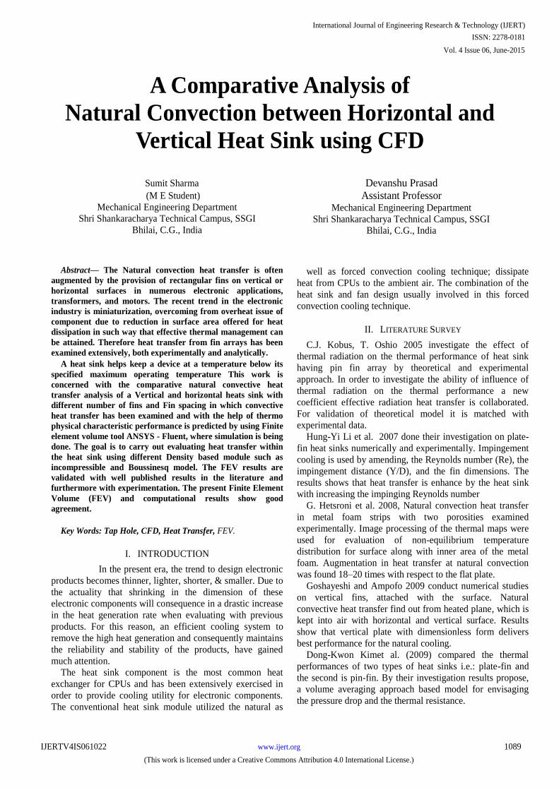
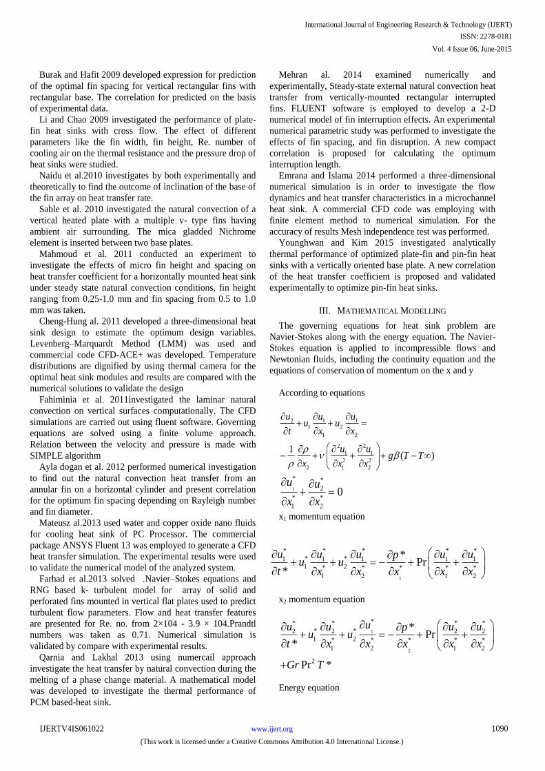
IV. METHODOLOGY
The ANSYS 14.5 finite element program was used to
analyze natural convection in differentially heated
enclosures. For this purpose, the key points were first
created and then line segments were formed. The lines were
combined to create a surface. Finally, this surface is
provided thickness model is made. We modeled 6 different
geometrical configurations of the heat sink with different
number of fins and fin spacing configuration. The heat sink
was discretized into 21788 elements with 44520 nodes. Heat
sink boundary conditions can also be applied in the mesh
section through naming the portion of modeled sink i.e.
Base, Base Top, Fins, Interior.
20 Fins
13 Fins
8 Fins
7 Fins
4 Fins
5 Fins
Figure 1 Geometry Modeling of Heat Sink
International Journal of Engineering Research & Technology (IJERT)
ISSN: 2278-0181
www.ijert.orgIJERTV4IS061022
(This work is licensed under a Creative Commons Attribution 4.0 International License.)
Vol. 4 Issue 06, June-2015
1091

20 Fins
13 Fins
8 Fins
7 Fins
4 Fins
5 Fins
Figure 2 Mesh Model
Table 1 Dimensions of the fin configuration
Fin Length
(L)
in mm
Fin width (W)
in mm
Fin thickness (t)
in mm
Base thickness
(d)
in mm
80 59.8 1 1.4
Fin height (H)
in mm
Fin spacing (s)
in mm
Number of fins (n)
29.2 2.1 20
29.2 3.9 13
29.2 7.4 8
29.2 8.8 7
29.2 13.7 5
29.2 18.6 4
International Journal of Engineering Research & Technology (IJERT)
ISSN: 2278-0181
www.ijert.orgIJERTV4IS061022
(This work is licensed under a Creative Commons Attribution 4.0 International License.)
Vol. 4 Issue 06, June-2015
1092
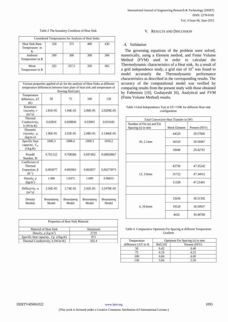
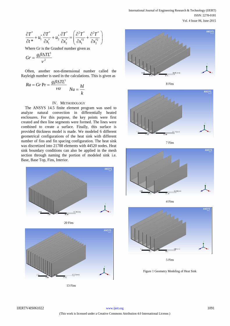
Table 2 The boundary Condition of Heat Sink
Considered Temperatures for Analysis of Heat Sinks
Heat Sink Base
Temperature in K
350 375 400 430
Ambient
Temperature in K
300 300 300 300
Mean Temperature in K
325 337.5 350 365
Various properties applied of air for the analysis of Heat Sinks at different
temperature differences between base plate of heat sink and temperature of
flowing fluid (air)
Temperature
difference, T
(K)
50
75
100
130
Kinematic viscosity, ν
(m2/s)
1.81E-05
1.94E-05
2.06E-05
2.0209E-05
Thermal Conductivity,
k (W/m-K)
0.02816
0.028836
0.03003
0.031045
Dynamic
viscosity, μ (kg/m-s)
1.96E-05
2.03E-05
2.08E-05
2.1466E-05
Specific heat
capacity, Cp
(J/kg-K)
1006.3
1008.4
1009.3
1010.2
Prandtl
Number, Pr
0.701122
0.708566
0.697402
0.69850067
Coefficient of
Thermal
Expansion, β (K-1)
0.003077
0.002963
0.002857
0.00273973
Density, ρ
(kg/m3)
1.086
1.0475
1.009
0.96655
Diffusivity, α
(m2/s)
2.56E-05
2.74E-05
2.92E-05
3.2478E-05
Density
Module
Boussinesq
Model
Boussinesq
Model
Boussinesq
Model
Boussinesq
Model
V. RESULTS AND DISCUSSION
A. Validation
The governing equations of the problem were solved,
numerically, using a Element method, and Finite Volume
Method (FVM) used in order to calculate the
Thermodynamic characteristics of a Heat sink. As a result of
a grid independence study, a grid size of 105 was found to
model accurately the Thermodynamic performance
characteristics as described in the corresponding results. The
accuracy of the computational model was verified by
comparing results from the present study with those obtained
by Fahiminia [10], Goshayeshi [6], Analytical and FVM
(Finite Volume Method) results.
Table 3 Grid Independence Test at ΔT=130K for different Heat sink
configuration
Total Convective Heat Transfer in (W)
Number of Fin (n) and Fin Spacing (s) in mm Mesh Element Present (FEV)
20, 2.1mm
44520 29.57845
36520 29.56967
16640 29.42761
13, 3.9mm
43750 47.35242
31752 47.34912
11328 47.21461
4, 18.6mm
12636 30.51392
10528 30.50927
4416 30.48760
Table 4 Comparative Optimum Fin Spacing at different Temperature Gradient
Temperature
difference (ΔT) in K
Optimum Fin Spacing (s) in mm
Ref.[10] Present (FEV)
50 6.42 6.40
75 6.19 6.15
100 6.04 6.00
130 5.84 5.50
Properties of Heat Sink Material
Material of Heat Sink Aluminum
Density, ρ (kg/m3) 2719
Specific heat capacity, Cp (J/kg-K) 871
Thermal Conductivity, k (W/m-K) 202.4
International Journal of Engineering Research & Technology (IJERT)
ISSN: 2278-0181
www.ijert.orgIJERTV4IS061022
(This work is licensed under a Creative Commons Attribution 4.0 International License.)
Vol. 4 Issue 06, June-2015
1093
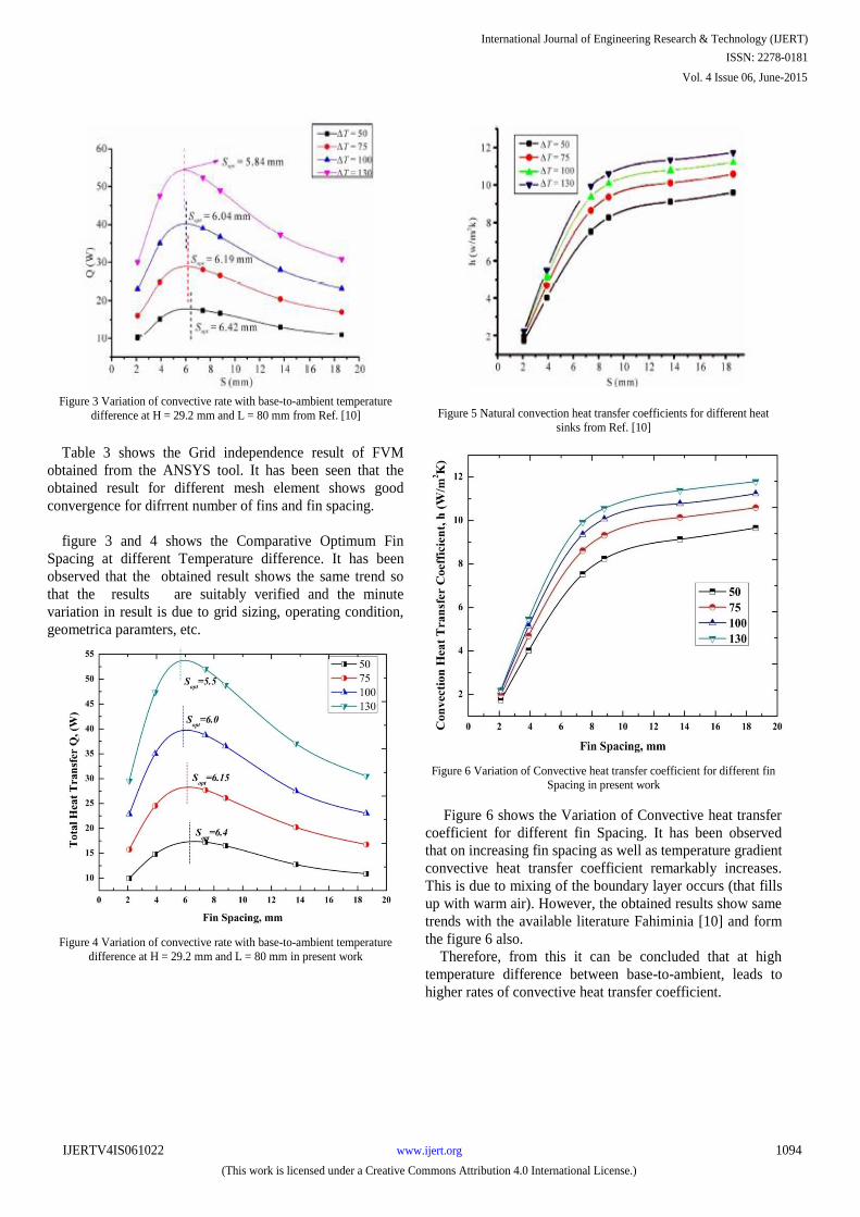
Figure 3 Variation of convective rate with base-to-ambient temperature
difference at H = 29.2 mm and L = 80 mm from Ref. [10]
Table 3 shows the Grid independence result of FVM
obtained from the ANSYS tool. It has been seen that the
obtained result for different mesh element shows good
convergence for difrrent number of fins and fin spacing.
figure 3 and 4 shows the Comparative Optimum Fin
Spacing at different Temperature difference. It has been
observed that the obtained result shows the same trend so
that the results are suitably verified and the minute
variation in result is due to grid sizing, operating condition,
geometrica paramters, etc.
Figure 4 Variation of convective rate with base-to-ambient temperature
difference at H = 29.2 mm and L = 80 mm in present work
Figure 5 Natural convection heat transfer coefficients for different heat
sinks from Ref. [10]
Figure 6 Variation of Convective heat transfer coefficient for different fin
Spacing in present work
Figure 6 shows the Variation of Convective heat transfer
coefficient for different fin Spacing. It has been observed
that on increasing fin spacing as well as temperature gradient
convective heat transfer coefficient remarkably increases.
This is due to mixing of the boundary layer occurs (that fills
up with warm air). However, the obtained results show same
trends with the available literature Fahiminia [10] and form
the figure 6 also.
Therefore, from this it can be concluded that at high
temperature difference between base-to-ambient, leads to
higher rates of convective heat transfer coefficient.
International Journal of Engineering Research & Technology (IJERT)
ISSN: 2278-0181
www.ijert.orgIJERTV4IS061022
(This work is licensed under a Creative Commons Attribution 4.0 International License.)
Vol. 4 Issue 06, June-2015
1094
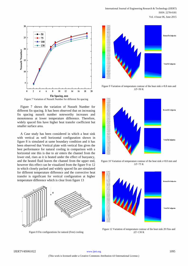
Figure 7 Variation of Nusselt Number for different fin spacing
Figure 7 shows the variation of Nusselt Number for
different fin spacing. It has been observed that on increasing
fin spacing nusselt number noteworthy increases and
monotonous at lower temperature difference. Therefore,
widely spaced fins have higher heat transfer coefficient but
smaller surface area.
A Case study has been considered in which a heat sink
with vertical as well horizontal configuration shown in
figure 8 is simulated at same boundary condition and it has
been observed that Vertical plate with vertical fins gives the
best performance for natural cooling in comparison with a
horizontal one this is due to air enters the channel from the
lower end, rises as it is heated under the effect of buoyancy,
and the heated fluid leaves the channel from the upper end,
however this effect can be visualized from the figure 9 to 12
in which closely packed and widely spaced fin are simulated
for different temperature difference and the convective heat
transfer is significant for vertical configuration at higher
temperature difference which is clear from figure 13
Figure 8 Fin configurations for natural (Free) cooling
Figure 9 Variation of temperature contour of the heat sink s=8.8 mm and ΔT=50 K
Figure 10 Variation of temperature contour of the heat sink s=8.8 mm and
ΔT=75 K
Figure 12 Variation of temperature contour of the heat sink 20 Fins and
ΔT=130 K
International Journal of Engineering Research & Technology (IJERT)
ISSN: 2278-0181
www.ijert.orgIJERTV4IS061022
(This work is licensed under a Creative Commons Attribution 4.0 International License.)
Vol. 4 Issue 06, June-2015
1095
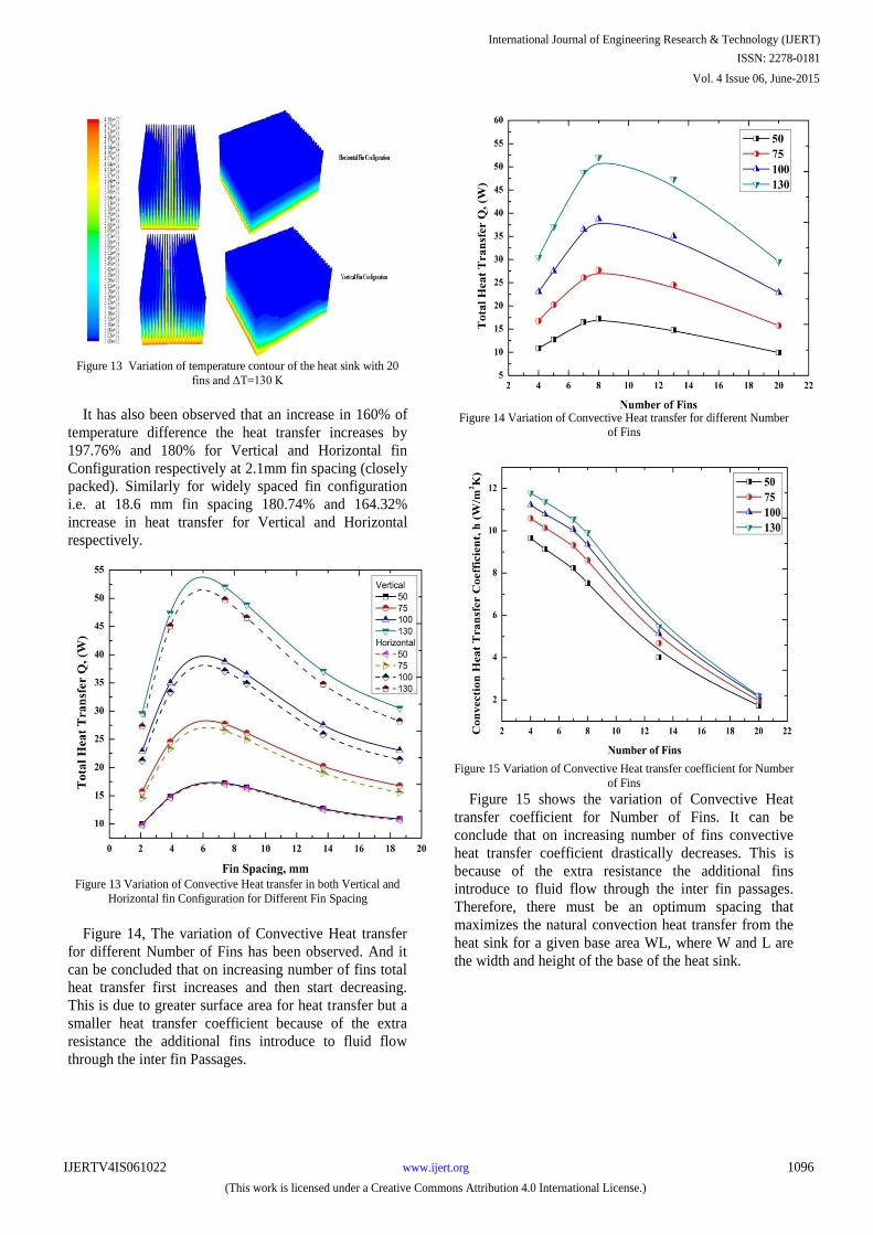
Figure 13 Variation of temperature contour of the heat sink with 20
fins and ΔT=130 K
It has also been observed that an increase in 160% of
temperature difference the heat transfer increases by
197.76% and 180% for Vertical and Horizontal fin
Configuration respectively at 2.1mm fin spacing (closely
packed). Similarly for widely spaced fin configuration
i.e. at 18.6 mm fin spacing 180.74% and 164.32%
increase in heat transfer for Vertical and Horizontal
respectively.
Figure 13 Variation of Convective Heat transfer in both Vertical and
Horizontal fin Configuration for Different Fin Spacing
Figure 14, The variation of Convective Heat transfer
for different Number of Fins has been observed. And it
can be concluded that on increasing number of fins total
heat transfer first increases and then start decreasing.
This is due to greater surface area for heat transfer but a
smaller heat transfer coefficient because of the extra
resistance the additional fins introduce to fluid flow
through the inter fin Passages.
Figure 14 Variation of Convective Heat transfer for different Number
of Fins
Figure 15 Variation of Convective Heat transfer coefficient for Number
of Fins
Figure 15 shows the variation of Convective Heat
transfer coefficient for Number of Fins. It can be
conclude that on increasing number of fins convective
heat transfer coefficient drastically decreases. This is
because of the extra resistance the additional fins
introduce to fluid flow through the inter fin passages.
Therefore, there must be an optimum spacing that
maximizes the natural convection heat transfer from the
heat sink for a given base area WL, where W and L are
the width and height of the base of the heat sink.
International Journal of Engineering Research & Technology (IJERT)
ISSN: 2278-0181
www.ijert.orgIJERTV4IS061022
(This work is licensed under a Creative Commons Attribution 4.0 International License.)
Vol. 4 Issue 06, June-2015
1096
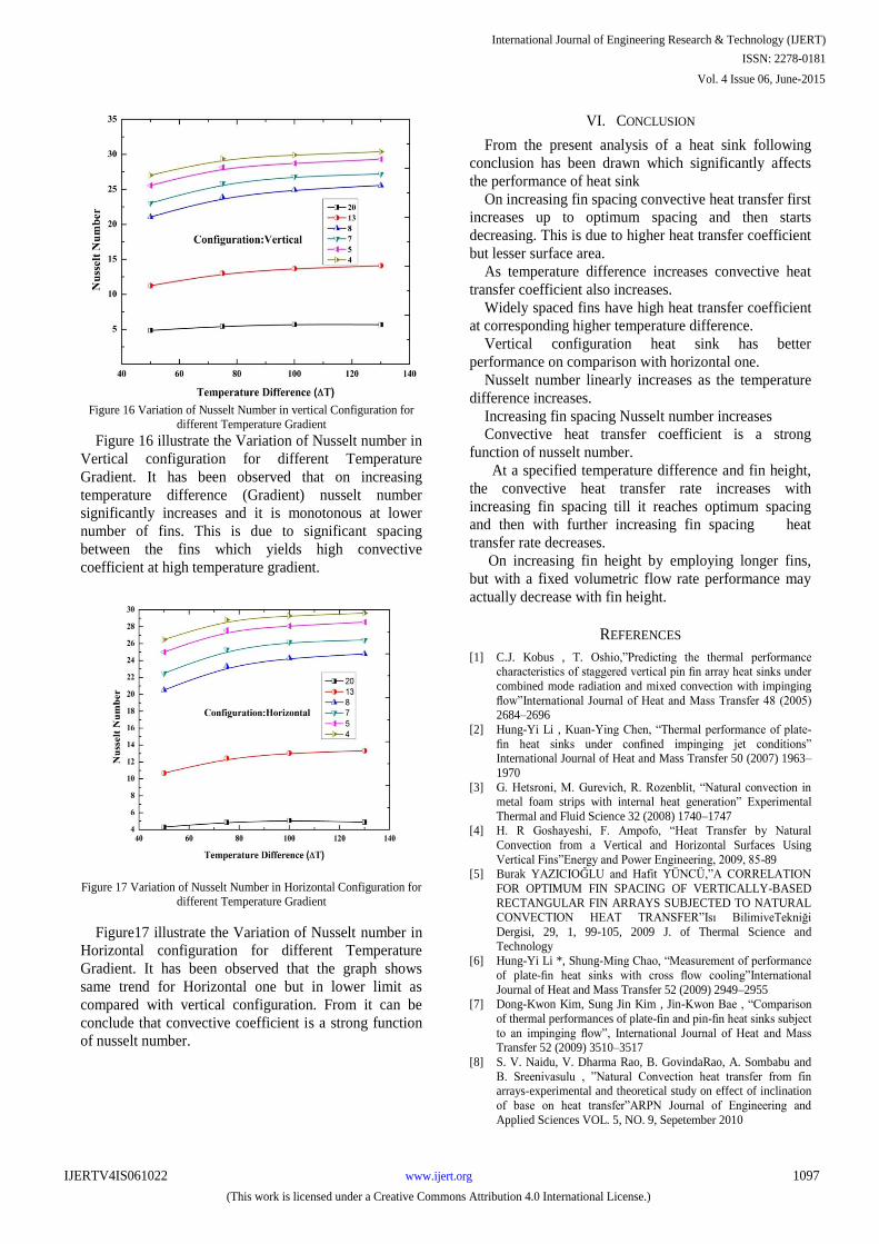
Figure 16 Variation of Nusselt Number in vertical Configuration for
different Temperature Gradient
Figure 16 illustrate the Variation of Nusselt number in
Vertical configuration for different Temperature
Gradient. It has been observed that on increasing
temperature difference (Gradient) nusselt number
significantly increases and it is monotonous at lower
number of fins. This is due to significant spacing
between the fins which yields high convective
coefficient at high temperature gradient.
Figure 17 Variation of Nusselt Number in Horizontal Configuration for different Temperature Gradient
Figure17 illustrate the Variation of Nusselt number in
Horizontal configuration for different Temperature
Gradient. It has been observed that the graph shows
same trend for Horizontal one but in lower limit as
compared with vertical configuration. From it can be
conclude that convective coefficient is a strong function
of nusselt number.
VI. CONCLUSION
From the present analysis of a heat sink following
conclusion has been drawn which significantly affects
the performance of heat sink
On increasing fin spacing convective heat transfer first
increases up to optimum spacing and then starts
decreasing. This is due to higher heat transfer coefficient
but lesser surface area.
As temperature difference increases convective heat
transfer coefficient also increases.
Widely spaced fins have high heat transfer coefficient
at corresponding higher temperature difference.
Vertical configuration heat sink has better
performance on comparison with horizontal one.
Nusselt number linearly increases as the temperature
difference increases.
Increasing fin spacing Nusselt number increases
Convective heat transfer coefficient is a strong
function of nusselt number.
At a specified temperature difference and fin height,
the convective heat transfer rate increases with
increasing fin spacing till it reaches optimum spacing
and then with further increasing fin spacing heat
transfer rate decreases.
On increasing fin height by employing longer fins,
but with a fixed volumetric flow rate performance may actually decrease with fin height.
REFERENCES
[1] C.J. Kobus , T. Oshio,”Predicting the thermal performance characteristics of staggered vertical pin fin array heat sinks under
combined mode radiation and mixed convection with impinging
flow”International Journal of Heat and Mass Transfer 48 (2005) 2684–2696
[2] Hung-Yi Li , Kuan-Ying Chen, “Thermal performance of plate-
fin heat sinks under confined impinging jet conditions” International Journal of Heat and Mass Transfer 50 (2007) 1963–
1970
[3] G. Hetsroni, M. Gurevich, R. Rozenblit, “Natural convection in metal foam strips with internal heat generation” Experimental
Thermal and Fluid Science 32 (2008) 1740–1747 [4] H. R Goshayeshi, F. Ampofo, “Heat Transfer by Natural
Convection from a Vertical and Horizontal Surfaces Using
Vertical Fins”Energy and Power Engineering, 2009, 85-89 [5] Burak YAZICIOĞLU and Hafit YÜNCÜ,”A CORRELATION
FOR OPTIMUM FIN SPACING OF VERTICALLY-BASED
RECTANGULAR FIN ARRAYS SUBJECTED TO NATURAL CONVECTION HEAT TRANSFER”Isı BilimiveTekniği
Dergisi, 29, 1, 99-105, 2009 J. of Thermal Science and
Technology
[6] Hung-Yi Li *, Shung-Ming Chao, “Measurement of performance
of plate-fin heat sinks with cross flow cooling”International
Journal of Heat and Mass Transfer 52 (2009) 2949–2955 [7] Dong-Kwon Kim, Sung Jin Kim , Jin-Kwon Bae , “Comparison
of thermal performances of plate-fin and pin-fin heat sinks subject
to an impinging flow”, International Journal of Heat and Mass Transfer 52 (2009) 3510–3517
[8] S. V. Naidu, V. Dharma Rao, B. GovindaRao, A. Sombabu and
B. Sreenivasulu , ”Natural Convection heat transfer from fin arrays-experimental and theoretical study on effect of inclination
of base on heat transfer”ARPN Journal of Engineering and
Applied Sciences VOL. 5, NO. 9, Sepetember 2010
International Journal of Engineering Research & Technology (IJERT)
ISSN: 2278-0181
www.ijert.orgIJERTV4IS061022
(This work is licensed under a Creative Commons Attribution 4.0 International License.)
Vol. 4 Issue 06, June-2015
1097
[9] J. Sable, S.J. Jagtap , P.S. Patil , P.R. Baviskar & S.B. Barve
,”Enhancement Of Natural Convection Heat Transfer On Vertical Heated Plate By Multiple V-FIN Array”IJRRAS 5 (2) November
2010
[10] Mahdi Fahiminia, Mohammad Mahdi Naserian, Hamid Reza Goshayeshi1, Davood Majidian, “Investigation of Natural
Convection Heat Transfer Coefficient on Extended Vertical Base
Plates”Energy and Power Engineering, 2011, 3, 174-180 [11] Cheng-Hung Huang , Jon-Jer Lu , Herchang Ay , “A three-
dimensional heat sink module design problem with experimental
verification” International Journal of Heat and Mass Transfer 54 (2011) 1482–1492
[12] S. Mahmoud , R. Al-Dadah , D.K. Aspinwall , S.L. Soo , H.
Hemida ,”Effect of micro fin geometry on natural convection heat transfer of horizontal microstructures” Applied Thermal
Engineering 31 (2011) 627-633
[13] H. El Qarnia , A. Draoui , E.K. Lakhal , “Computation of melting with natural convection inside a rectangular enclosure heated by
discrete protruding heat sources” Applied Mathematical
Modelling 37 (2013) 3968–3981
[14] Mateusz Korpyś, Mohsen Al-Rashed, Grzegorz
Dzido,aJanuszWójcika , “CPU Heat Sink Cooled by Nanofluids
and Water Experimental and Numerical Study” Proceedings of the 23rd European Symposium on Computer Aided Process
Engineering – ESCAPE 23, June 9-12, 2013, Lappeenranta,
Finland [15] Mehran Ahmadi, Golnoosh Mostafavi, Majid Bahrami, “Natural
convection from rectangular interrupted fins”International Journal of Thermal Sciences 82 (2014) 62-71
[16] Md. Emrana, Mohammad Ariful Islama, “Numerical
investigation of flow dynamics and heat transfer characteristics in a microchannel heat sink” Procedia Engineering 90 ( 2014 )
563 – 568
[17] Younghwan Joo a, Sung Jin Kim, “Comparison of thermal performance between plate-fin and pin-fin heat sinks in natural
convection” International Journal of Heat and Mass Transfer 83
(2015) 345–356.
Nomenclature
g Acceleration due to gravity, m s−2
k Thermal conductivity, W m−1
K−1
L Side of the Wall, m
N Normal direction on a wall
Nu Local Nusselt number
P Dimensionless fluid pressure
Pr Prandtl number
Ra Rayleigh number
Re Reynolds number
Gr Grashof number
T Fluid temperature, K
u x component of velocity
U x component of dimensionless
velocity
v y component of velocity
V y component of dimensionless
velocity
X Dimensionless distance along x
coordinate
Y Dimensionless distance along y
coordinate
τ stress
τp non-dimensional ramp time
ε Emissivity
z Axial Coordinate
Greek Symbols
α Thermal diffusivity, m2 / s
β Thermal expansion coefficient at
constant pressure, K−1
ρ Density, kg m−3
cp Specific heat coefficient, J/kg-K
cv Specific heat coefficient, J/kg-K
φ Angle
International Journal of Engineering Research & Technology (IJERT)
ISSN: 2278-0181
www.ijert.orgIJERTV4IS061022
(This work is licensed under a Creative Commons Attribution 4.0 International License.)
Vol. 4 Issue 06, June-2015
1098