a case study in robot exploration - the robotics … · 1 1. introduction we report on a case study...
TRANSCRIPT
A Case Study in Robot Exploration
Long-Ji Lin, Tom M. Mitchell Andrew Philips, Reid Simmons
CMU-R I-TR-89- 1
Computer Science Department and
The Robotics Institute Carnegie Mellon University
Pittsburgh, Pennsylvania 1521 3
January 1989
0 1989 Carnegie Mellon University
This research was supported by NASA under Contract NAGW-1175.


i
Table of Contents 1. Introduction 2. System Description
2.1. The Robot Testbed 2.2. The Task and Approach
3. System Performance 4. Lessons from The Case Study
4.1. Characteristics of the Prototype System 4.2. Pervasive Uncertainty 4.3. Target Capabilities for the Task Control Architecture
5. Acknowledgements
1 2 2 3 7 9 9
10 11 12

Abstract
This paper reports on a case study in autonomous robot exploration. In particular, we describe a working mobile manipulator robot that explores our laboratory to identify and collect cups. This system is a first step toward our research goal of developing an architecture for robust robot planning, control, adaptation, error monitoring, error recovery, and interaction with users. We describe the current system, lessons learned from our earlier failures, organizing principles employed in the current system, and limits to the current approach. We also discuss the implications of this work for a more robust robot control architecture which is presently under development.

1
1 . Introduction We report on a case study in autonomous robot exploration. In particular, we describe a working
mobile manipulator robot that explores our laboratory in search of cups. This system is a first step toward our research goal of developing a robust architecture for robot exploration tasks, covering planning, control, error monitoring and recovery, adaptation, and communication with users. It is also intended as a testbed for better understanding the task of semi-autonomous robot exploration and sample collection. The robot exploration task is of specific interest to us, given a related effort to develop a prototype robot to explore the surface of Mars to collect geological samples [l]. This testbed is thus intended both to help explore characteristics of the Mars Rover task, and as a general carrier for a broad range of research on autonomous intelligent robots.
The robot exploration task considered here is one in which a mobile robot with an attached manipulator explores an area using vision and sonar sensors in order to locate and identify cups. When a cup-like object is located, the robot navigates to it and uses more detailed sensing to determine whether it is truly a cup, and if so what type. It then picks up the cup, travels to a box, deposits the cup, and looks for additional cups to collect.
This task raises a number of general issues that must be addressed for exploration tasks, as well as specific issues that must be addressed in the Mars Rover scenario. These include:
0 Path planning and navigation
0 Observing and identifying encountered objects
0 Integrating locomotion with manipulation and perception.
Maintaining background goals (e.g., battery charge level) while pursuing the current goal
0 Detecting errors (e.g., the cup was not grasped correctly) and recovering from them.
0 Communicating and collaborating with a remote human for guidance in dealing with difficult
(e.g., pick up the object).
tasks.
Our present system deals well with some of the above issues, and poorly with others. The implemented system autonomously locates cups, navigates to them, picks them up, and deposits them in a bin. However, it does not presently manage multiple goals, deal well with unexpected contingencies, or collaborate with humans.
This paper describes the current system, lessons learned from our earlier failures, organizing principles employed in the current system, and limits to the current approach. We also discuss what we have learned from this work regarding specific problems that must be addressed by the architecture currently under design. Section 2 describes in greater detail the hardware setup, task, and approach taken for this exploration task. Section 3 characterizes the performance of the system, including interesting failures which it has exhibited. Finally, section 4 characterizes lessons learned from this case study, and implications for the design of more robust architectures for robot planning and control.
2
2. System Description
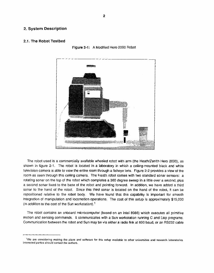
2.1. The Robot Testbed Figure 2-1 : A Modified Hero 2000 Robot
The robot used is a commercially available wheeled robot with arm (the HeatNZenith Hero 2000), as shown in figure 2-1. The robot is located in a laboratory in which a ceiling-mounted black and white television camera is able to view the entire room through a fisheye lens. Figure 2-2 provides a view of the room as seen through this ceiling camera. The Heath robot comes with two standard sonar sensors: a rotating sonar on the top of the robot which completes a 360 degree sweep in a little over a second, plus a second sonar fixed to the base of the robot and pointing forward. In addition, we have added a third sonar to the hand of the robot. Since this third sonar is located on the hand of the robot, it can be repositioned relative to the robot body. We have found that this capability is important for smooth integration of manipulation and locomotion operations. The cost of this setup is approximately $1 5,000 (in addition to the cost of the Sun workstation).'
The robot contains an onboard microcomputer (based on an Intel 8086) which executes all primitive motion and sensing commands. It communicates with a Sun workstation running C and Lisp programs. Communication between the robot and Sun may be via either a radio link at 600 baud, or an RS232 cable
'We are considering making the plans and software for this setup available to other universities and research laboratories. Interested parties should contact the authors.

3
Figure 2-2: Overhead View of Laboratory as Seen by Robot
at 9600 baud. In practice, we have found the 600 baud radio link constitutes a communications bottleneck, and therefore frequently utilize the more awkward but faster RS232 tethered connection. Table 2-1 summarizes the sensor, effector, and computational characteristics of the robot testbed.
2.2. The Task and Approach As stated earlier, the robot task is to collect cups into a container in the corner of the lab. The top-level
procedure used by the system to accomplish this task is described in table 2-2. Below we discuss in additional detail each of the steps in this high-level plan.
Locate robot, potential cups, and obstacles. The system begins by examining the visual image from the ceiling camera to locate regions that correspond to potential cups, the robot, and other obstacles. The image is thresholded and regions extracted by the Phoenix program [5]. The robot region is located based on searching a window within the visual field, centered around the current expected location of the robot. Within this window, the robot region is identified based on a simple model of the properties of its region in the visual field. Potential cup regions are identified by searching the entire visual field for regions whose size and shape match those of cups. Since the resolution of this image is fairly coarse (approximately 1 inch per pixel), and since a simple thresholded black and white image is used, it is possible for the system to identify non-cup regions (e.g., sneakers worn by lab residents) as potential cups. In figure 2-2, it is possible to see several cup-sized regions in the image. The robot will navigate to each of these regions, using its sonar to explore each in turn. Those which it eventually determines are not cups are remembered as such, in order to avoid examining them repeatedly.
4
~~ ~
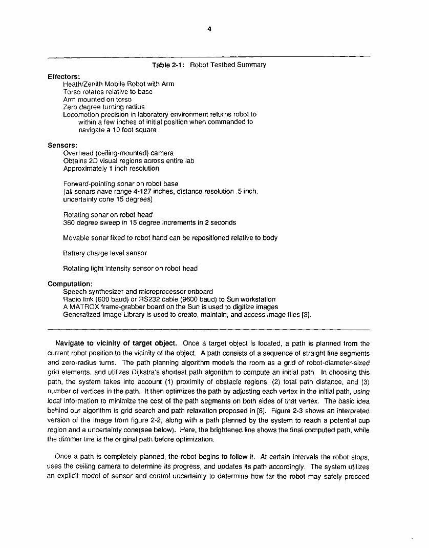
Table 2-1 : Robot Testbed Summary
Effectors: Heath/Zenith Mobile Robot with Arm Torso rotates relative to base Arm mounted on torso Zero degree turning radius Locomotion precision in laboratory environment returns robot to
within a few inches of initial position when commanded to navigate a 10 foot square
Sensors: Overhead (ceiling-mounted) camera Obtains 2D visual regions across entire lab Approximately 1 inch resolution
Fotward-pointing sonar on robot base (all sonars have range 4-1 27 inches, distance resolution .5 inch, uncertainty cone 15 degrees)
Rotating sonar on robot head 360 degree sweep in 15 degree increments in 2 seconds
Movable sonar fixed to robot hand can be repositioned relative to body
Battery charge level sensor
Rotating light intensity sensor on robot head
Corn put at ion : Speech synthesizer and microprocessor onboard Radio link (600 baud) or RS232 cable (9600 baud) to Sun workstation A MATROX frame-grabber board on the Sun is used to digitize images Generalized Image Library is used to create, maintain, and access image files [3].
Navigate to vicinity of target object. Once a target object is located, a path is planned from the current robot position to the vicinity of the object. A path consists of a sequence of straight line segments and zero-radius turns. The path planning algorithm models the room as a grid of robot-diameter-sized grid elements, and utilizes Dijkstra’s shortest path algorithm to compute an initial path. In choosing this path, the system takes into account (1) proximity of obstacle regions, (2) total path distance, and (3) number of vertices in the path. It then optimizes the path by adjusting each vertex in the initial path, using local information to minimize the cost of the path segments on both sides of that vertex. The basic idea behind our algorithm is grid search and path relaxation proposed in [8]. Figure 2-3 shows an interpreted version of the image from figure 2-2, along with a path planned by the system to reach a potential cup region and a uncertainty cone(see below). Here, the brightened line shows the final computed path, while the dimmer line is the original path before optimization.
Once a path is completely planned, the robot begins to follow it. At certain intervals the robot stops, uses the ceiling camera to determine its progress, and updates its path accordingly. The system utilizes an explicit model of sensor and control uncertainty to determine how far the robot may safely proceed

5
Do until no potential target objects remain:
Locate robot, potential target objects, and obstacles within visual field Find visual regions Identify those with appropriate features
Plan obstacle-free path to vicinity Move along path, monitoring with vision
Use sonar to locate nearest object in appropriate direction Servo using sonar until target centered at 0 degrees, 6.5 inches ahead Classify object as non-cup or specific type of cup
Grasp cup, based on identified cup type Make final approach to grasping position Move arm and gripper to grasp cup Use top sonar to determine whether arm successfully grasped object
Configure arm and body for safe travel Navigate to container Orient to center container in front of robot Deposit cup in container
Navigate to vicinity of target
Approach and identify target
Table 2-2: Top-Level Cup Exploration Procedure
~~~~~~ ~~ ~ ~ ~~~~~
Figure 2-3: Interpreted Overhead View With Planned Path and Uncertainty Cone
along its path before a new visual check is required. A covariance matrix representation [7] of uncertainty is used. Robot location and orientation are calculated by merging information from both dead reckoning and vision. The system introduces a new sensing operation when uncertainties in sensing and control have grown to the extent that either (1) collisions with obstacles are possible, (2) the uncertainty modeler is unable to model uncertainty accurately, or (3) the visual recognition routines which utilize strong expectations about robot location do not have strong enough expectations to operate reliably.
By modifying an old path, the path planner can efficiently adapt to small environmental changes, such as the robot wandering slightly off the planned path, new obstacles appearing, and old ones

6
disappearing.
Figure 2-4: Sonar Data Obtained by Wrist Sonar Observing a Cup
Distance 35 I of Sonar I 0 .
Echo 3 0 I ( inches) I
25 I I
20 I I
15 I I
10 I I
5 1 a w e .
0
I 0 -25 -20 -15 -10 -5 0 5 10 15 20 25
W r i s t angle (degrees)
The data i n angle-distance pairs is: (-25 31) (-20 32) (-15 32.5) (-10 7) (-5 7) (0 6.5) (5 6.5) (10 7) (15 7.5) (20 24.5) (25 24).
The data was taken while two boxes w e r e placed on the background of the cup.
Approach and identify target. Navigation under the direction of vision is able to place the robot within several inches of its desired location. In order to successfully grasp an object, however, the relative position of the robot and object must be controlled with significantly greater precision (on the order of an inch or less). Thus, once the robot reaches the vicinity of the target object, it utilizes its sonar to locate itself more precisely relative to the target object and to classify it. Figure 2-1 shows the pose which the robot assumes in order to utilize its wrist sonar to detect the location and dimensions of the object. The wrist is rotated from side to side in order to sweep directly ahead and detect the object. This sweep provides a one-dimensional horizontal array of sonar data giving distance readings as a function of wrist angle. Figure 2-4 shows a typical set of data obtained by the hand sonar when observing a cup in this fashion. Simple thresholding, edge finding, and region finding routines are then used to process this one-dimensional array in order to locate the object in the sonar field of view.
Once the object is located in the sonar field, its distance and orientation are used to compute robot locomotion commands to bring the object to 0 degrees (plus or minus 2 degrees) and 6.5 inches (plus or minus .5 inch) in front of the wrist sonar. To overcome sensing and control errors, this procedure is repeated after the locomotion commands are executed until the sonar detects the object at the desired position. Typically, this servo loop requires from 1 to 3 cycles before convergence. Once in position, the object width and height are measured (in degrees of wrist motion) to identify the object as either (a) an upright standard-sized Styrofoam coffee cup, (b) an upright Roy-Rogers Big Chiller cup, or (c) neither.
Grasp object. If the object is identified as one of the two known types of cups, then it is grasped by a procedure specific to that object. The grasping operation itself does not use sensory feedback to guide the hand--all the sensing work is performed during the precise positioning of the robot during its approach

7
to the object. With this reliability in positioning, it is fairly rare for the grasping operation to fail. Note that the lack of a need for sensing here is due in part to the fact that the object shape and dimensions are know a priori, and to the predictability of the physics of interaction between the gripper and object. If one were to attempt picking up a rock of unknown size and shape half buried in the sand, significant sensing would most likely be essential to monitor the details of the manipulation operation.
Once the grasp action is completed, the robot raises its hand so that the object which it is (presumably) holding may be detected by the head sonar. This check allows the system to verify the success of the grasping operation. If it instead detects failure, then the system labels the corresponding visual region as a "fools-cup" and subsequently avoids it. No attempt is presently made to replan or recover from manipulation errors, though this is a topic we intend to pursue in the future.
Navigate to container and deposit cup. Once a cup has been successfully obtained, it is tucked in to protect the arm during travel, and a path is planned to the container. The cup is then deposited, and once again the system looks for a new cup to collect.
3. System Performance The system described above is fairly successful at locating and collecting cups. We estimate that it
succeeds approximately 80-90% of the time in finding, retrieving, and depositing cups that are placed on the floor away from the perimeter of the room in unobstructed view of the camera. It typically requires on the order of 5 minutes to locate a candidate cup, navigate to it, pick it up, and drop it off in the container (when communicating via the 9600 baud tether). Approximately half of this time is spent navigating to the cup and later to the container to drop it off. The other half is spent near the cup, refining the relative position of the robot and cup, identifying the object, and grasping it. The overall time increases by a factor of three when using the 600 baud radio link, indicating that when the radio link is used the system bottleneck is the low baud fate communication link which must pass commands from the Sun to the robot, and sensor data from the robot back to the Sun.
Since many of the most interesting lessons we have learned arise from observing failures of the system, we summarize several of these encountered failures in table 3-1. The point to notice about these failures is that they typically arise either because of lack of appropriate sensing (e.g., the collision of the hand against the table when picking up a cup under the table edge), outright errors in sensing (e.g., when the short cup is not found by the sonar), or because of our lack of imagination in anticipating the many possible interactions between subparts of the procedure (e.g., that after picking up the cup, the robot would refuse to move because the vision system saw the cup held in front of the robot as an obstacle!).
Perhaps some of these errors could have been avoided had we originally included more sensing on the robot's part or more imagination on our own. However, the nature of unengineered environments is that they provide a continual source of novel and unanticipated contexts, interactions and errors (e.g., a cup found beneath the edge of the table, a second cup positioned unfortunately near the target cup so that it is run over). It seems unlikely that one can expect to anticipate all possible interactions and novel situations in advance.
Given that such unanticipated events are bound to occur, and given that the system cannot afford to sense everything that goes on in the environment, an important question is exactly what needs to be sensed at a minimum to assure basic survival of the robot, and what kinds of sensors and sensor

8
Table 3-1 : Typical System Failures and Causes or Repairs
Vision system fails to find robot. 0 This can happen when the robot region overlaps another visual region. This is usually not
fatal, since the system then uses the expected robot location (based on dead reckoning) in place of observed location, and proceeds.
Misses container when it deposits cup. This can occur due to sensing error in the visual determination of the robot orientation relative to the container. This could be overcome by more tedious servoing with the sonar to center the robot in front of container to some desired tolerance.
Robot fails to dock successfully with battery charger. 0 This is due to the fact that we initially underestimated the tolerance of the docking element to
error in the robot position, and overestimated the sensor error involved in using the sonar to position the robot relative to the docking element. As a result, the system refuses to dock because it believes it is not positioned precisely enough relative to the docking element, despite the fact that it is! This failure is interesting in that it is a direct consequence of the difficulty of estimating sensor and control errors in advance.
Runs over other cups when trying to grasp one of them 0 This is because approach and grasp routines do not watch out for obstacles.
Execution monitoring causes failure if person walks through field, and is seen as an obstacle This is because system does not distinguish moving from nonmoving objects.
Finds non-cup objects (e.g., sneakers) which appear visually to be cups. These are generally identified as non-cups upon closer examination. But they can result in considerable wasted time.
Time was wasted conducting sonar sweeps at needlessly detailed resolution while positioning robot relative to cup.
This is due to the fact that we could not accurately know in advance how fine-grained the sonar sensing should be (Le., collect a reading every 2, 5 , or 10 degrees). Once we experimented and determined that we had chosen an overly conservative value, we decreased the resolution to increase efficiency without increasing the error rate.
Arm collides with table after picking up cup that is under edge of table. This occurs when the robot raises its hand to use the head sonar to determine whether it has successfully grasped the cup. Due to failure to check hand trajectory for collisions.
Robot unable to navigate to container, because grasped cup is now seen by vision system as an obstacle in front of robot(!)
This was repaired by having the robot hold the cup behind itself. Vision still sees the cup as an obstacle, but now it is behind the robot.
placements simplify the processing of this sensor data. As an example of a reasonable sensing strategy,
9
consider that by implementing arm motions so that the (movable) wrist sonar is pointed in the direction of the arm sweep, it is possible to use this sonar sensor as a proximity sensor to detect unanticipated collisions before they occur. This strategy would allow the system to avoid damaging itself even when unanticipated situations arise, such as raising the cup from beneath the table. Once this sensed condition were detected, it could be used as a trigger to attempt to explain and recover from the failure.
4. Lessons from The Case Study This section summarizes organizing characteristics of the current system, discusses the impact of
uncertainties on the task, and suggests capabilities that we intend to incorporate in future extensions to the current system.
4.1. Characteristics of the Prototype System Few general-purpose approaches were needed. Although the general problem of planning arm trajectories and grasping motions is very difficult, we found little need for such methods. Instead, we defined a simple, fixed, blind grasping routine, determined the context in which it would succeed (Le., the relative position and orientation of the cup and the tolerance to error in this relative position), and then designed the remainder of the system to assure that the robot would position itself so that this specialized routine would succeed. Thus, the system gets away with simple, specialized grasping at the cost of stronger demands on the routines that must position the robot relative to the cup. A similar situation holds for the problem of object identification. Classifying object identity from an arbitrary distance and vantage point is a computationally demanding task, which is avoided in this case by servoing to a known vantage point before attempting to identify the object2. The acceptability of such specialized procedures for grasping and object identification suggests that solutions to general problems can sometimes be found by embedding specialized methods inside larger procedures that assure these procedures are only invoked within specialized contexts. This system organization involving collections of coupled, but specialized, routines is similar to that advocated in [2]. The one major case in which general purpose planning is used in the system is in the path planning component. We see no way to avoid the need for such general-purpose solutions in this case.
Explicit reasoning about sensor and control uncertainty allows intelligent utilization of expensive sensing operations. The first implementation of the system monitored the robot navigation by employing a visual check at each vertex of the robot’s path. This was subsequently replaced by a strategy that selects appropriate sensing operations based on a model of the vision sensing and robot motion uncertainties as well as the positions of obstacles. This shift resulted in both a significant speedupheduction in the number of vision operations typically performed, and an increase in reliability of navigation in cluttered environments.
Both low-level and high-level sensor features used in decision making. The sensor data is generally interpreted in terms of features at differing levels of abstraction. For example, a sonar data sweep gives rise to a one-dimensional array of distance versus angle readings. This array is interpreted to find progressively higher level features such as sonar edges, regions, region widths, and object identities. We found it useful for the decision- making procedures of the robot to utilize all of these levels of interpreted data in various contexts. For example, raw sonar readings are used to determine whether the cup is in the robot’s hand, whereas sonar edges are used to decide on the object height, and region
’Note the fact that the cup is a cylindrical object allows cleanly separating object identification from positioning the robot at a known vantage point relative to the object. It would be interesting to extend this approach to objects that lack this cylindrical symmetry.
10
widths are used to determine the object diameter. This suggests that it will be important for the perception module of our new architecture to allow access to sensor data at multiple levels of abstraction.
0 Multiple Coordinate frames found useful. We also found it useful for the system to reason in differing coordinate frames. The world-centered coordinate frame is used for path- planning and navigation tracking, whereas a wrist-oriented coordinate frame is used to describe the expected dimensions of the known types of cups (since this is the coordinate frame in which the raw sensor data is produced). We also found it easiest to use the wrist coordinate frame to describe the desired and observed position of the cup relative to the robot. Converting to the world-coordinate frame in this case introduces needless computation and rounding errors (though it is possible that doing so would make it easier to avoid obstacles whose positions are described in the world coordinate frame).
0 Communications bottleneck indicates that computational complexity is relatively low. The fact that the 600 baud radio link causes a very significant slowdown in the overall system is an indication that the processing demands of this task are relatively small compared to communication demands. Of course it is not clear that this would continue to be the case in less structured environments, or as the system is scaled up to handle more sensors, or to respond to dangerous situations in real time.
4.2. Pervasive Uncertainty The robot faces many types of uncertainty. It lacks a perfect description of its world, because its
sensors cannot completely observe the world. In addition, it lacks a perfect characterization of the effects of its actions, so that even if it had a perfect characterization of its world it (and we) would have difficulty constructing perfect plans in advance of executing them. These are commonly cited difficulties of real- world robotics problems.
One type of uncertainty that has been especially important in the development of this system is our own uncertainty about the sensor and control errors of the robot. For example, when developing the routine to position the robot in front of the cup, we did not know what resolution to use for the sonar sweep (Le., should the robot scan from -45 to 45 degrees in 1 degree increments, or something else). We also did not know how precisely the robot would have to be positioned relative to the cup (0 degrees and 6 inches, plus or minus what error tolerance?). In fact, we simply picked numbers for these parameters, and then tested the system. If it failed to successfully grasp the cup, we increased the sensor resolution or the positioning tolerance. If it succeeded but operated too slowly, then we decreased these parameters. The point is that correct values for these parameters are impossible to derive in advance, unless one knows in detail the sonar reflectance properties of the object, the spread in the sonar signal as it travels, the tolerance of the gripping action to errors in relative position, etc. We did not know these facts, but found it fairly simple to guess some initial parameter values and then increase or decrease as needed.
This has significant implications for the feasibility of automatic planning by the robot to deal with new situations (consider something as simple as planning to pick up a new type of cup). We believe it may be easier for such automatic planning to proceed by selecting and then adapting parameter values through experience, just as we found ourselves doing, rather than attempting to plan correctly all parameter values based on a detailed analysis of the physics and models of sensor and control errors (as suggested, for example, in [4]). We intend to explore this type of robot learning in the future.
11
4.3. Target Capabilities for the Task Control Architecture We are presently reimplementing an extended version of the prototype system within a more principled
architecture that is intended to increase the robustness of the system [6]. In particular, we intend to this architecture to provide new capabilities including:
0 Reacting to a changing world. If the system is attempting to reach a cup and the cup tips over, or someone picks it up, or a new obstacle appears in its path, the robot should react appropriately to these changes in its world. To do so requires at a minimum the sensing capability and focus of sensor attention to detect such changes. But it also requires determining an appropriate response in an appropriate time frame, while gracefully discontinuing the current activity of the robot. Our new architecture is intended to support such reactive abilities by maintaining dependencies between sensed data and current goals and subgoals. Such dependencies will be used to determine which, if any, current goals or beliefs should be revised in the face of changing sensor data.
0 Supporting multiple goals. The current system has no explicit goals, though implicitly its procedures cause it to appear to exhibit goal-directed behavior. A realistic system should have multiple explicit goals (e.g., "maintain the battery charge", "obtain cups", "avoid obstacles"). We intend for our architecture to support such multiple goals, and to be able to switch among them as appropriate. For instance, if the robot is approaching a cup and finds that its battery charge is becoming dangerously low, it should suspend its attempts to achieve the "obtain cup" goal in order to attend to the higher priority "recharge battery" goal, and then later resume the interrupted activity.
0 Temporarily overriding or undoing achieved goals. Once the system has multiple goals, then subtle interactions can occur. For example, if the robot is carrying the cup to the container and encounters an impassable field of obstacles, then it might need to put the cup down and use its hand to clear its path of obstacles. Afterwards, it should pick up the cup and continue to pursue its original goal. This type of overriding and undoing a partially achieved goal (putting down the cup which has already been successfully grasped) and later resuming, is typical of the kind of goal interactions we believe our architecture must support.
0 Detecting and recovering from errors. The present system is able to detect some types of errors (e.g., to determine that it failed to grasp the cup). We intend for our architecture to support more complete error detection as well as reasoning about how to recover from certain types of errors. For example, if it is determined that the system failed to pick up the cup, the system should attempt to characterize why (e.g., it was not a cup, but only a round piece of paper on the floor; or the cup was tipped over during the grasping operation), and to replan accordingly. General error detection and recovery is extremely difficult, but we believe that all dangerous errors must at least be detected and dealt with to assure the survival goal of the robot is maintained. Beyond that, we also intend to explore recovering from certain errors in a fashion that allows the original goal to be effectively achieved.
0 Collaborating with remote human advisor. We desire for our system to communicate with a remote human advisor/commander in order to obtain new commands and to obtain advice about how to deal with difficult situations that arise in pursuing its goals. This is an especially important issue in the context of the Mars Rover project, in which such collaboration must occur under the constraint of large time delays. Here, the usual methods of human teleoperation do not work well. Instead, the robot must play a much greater role in deciding when intervention is needed and what information to send to the human to allow him/her to help make the decision. In the context of the current testbed, we intend to study such issues by allowing the robot to communicate with a person in another room. For example, if the robot finds that it has failed to place the cup correctly in the container, then it may decide (a) to try again, (b) to ask for assistance and send appropriate information regarding the current situation and plausible cause of the error, or (c) to do both in parallel.
12
5. Acknowledgements We are grateful to John Allen, who helped set up the original robot equipment and helped develop the
interface between the Sun and robot. We thank Takeo Kanade and his group for providing the Generalized Imaging Library routines which provide the low-level vision processing in this system. Jim Moody has been a great help in getting the vision hardware and software set up correctly. Similarly, Steve Shafer provided expertise and assistance in helping select appropriate vision hardware and software. This research has been supported by NASA under Contract NAGW-1175.
13
References
[41
[51
Bares, J., et at. An Autonomous Rover for Exploring Mars. IEEE Computer Magazine , . Special Issue on Autonomous Intelligent Machines. Submitted September, 1988.
Brooks, R.A. A Robust Layered Control System for a Mobile Robot. IEEE Journal of Robotics and Automation 2(1), March, 1986.
Hamey, L., Printz, H., Reece, D., and Shafer, S.A. A Programmer’s Guide to the Generalized Image Library Carnegie Mellon University, 1987. CMU I U S document.
Lozano-Perez, T., Mason, M.T., Taylor, R.H. Automatic Synthesis of Fine-Motion Strategies for Robots. International Journal of Robotics Research 3(1):3-24, 1984.
Shafer, S.A., and Kanade, T. Recursive Region Segmentation by Analysis of Histograms. In Proc. Intl. Conf. on Acoustics, Speech, and Signal Processing, pages 11 66-1 171. IEEE, May,
Simmons, R., and Mitchell, T.M. A Task Control Architecture for Mobile Robots. Technical Report, ,1989. Submitted to AAAl Symposium on Robot Navigation.
Smith, R.C., and Cheeseman, P. On the Representation and Estimation of Spatial Uncertainty. In The International Journal of Robotics Research, pages 56-68. 1986.
Thorpe, C.E. FIDO: Vision and Navigation for a Robot Rover. Technical Report, CMU-CS-84-168, Carnegie Mellon University, 1984.
1982.