a broadband ase light source-based fttx rof-wdm...
TRANSCRIPT

Journal of Network Intelligence c⃝2016 ISSN 2414-8105(Online)
Taiwan Ubiquitous Information Volume 2, Number 1, February 2017
A Broadband ASE Light Source-based FTTXRoF-WDM Optical Network System
S. H. Meng
Key Laboratory of Big Data Mining and Application/School of Information Science and EngineeringFujian University of Technology
No. 3, Xueyuan Rd., University Town, 350118 Fuzhou City, Fujian Province, [email protected]
S.B. Hu
Institute of Electro-Optical Science and EngineeringNational Cheng Kung University
70101 Tainan, Taiwan
H. C. Chu∗
Institute of Electro-Optical Science and EngineeringNational Cheng Kung University
70101 Tainan, [email protected]
C. H. Chang
Department of Electrical EngineeringNational Chiayi University
Chaiayi, Taiwan
S.-C. Chu
Flinders University, [email protected]
Received October 2016; revised February 2017
Abstract. A enhanced network quality factors with noise interference elimination overFTTX RoF-WDM Optical Network System. This solution combines the concepts of long-distance transmission and ring topology. It is effective in expanding the bandwidth toovercome network congestion and in addressing the issues in wired optical fibers and wire-less microwave communication systems. The potential amplified spontaneous emissionbroadband light source and spectrum-slicing technology are integrated with the dynam-ic reconfigurable optical add-drop multiplexer to decentralize the management of FTTXRoF-WDM-wavelength-division multiplexed optical network, which optimizes the trans-mission performance and eliminates multi-path crosstalk. We proved that the flat-gainsignal optimization and the semiconductor optical amplifier structure enhance the opticalsignal and optical signal-to-noise ratio. The downlink quality factor curves in the Q6 da-ta showed an -18.8 dBm increase in the received optical power. Application of the FTTXRoF-WDM broadband access network system achieved low crosstalk, a clear eye diagram,and an eye 3D graph. Since our proposed system uses only a broadband ASE light sourceto achieve multi-wavelengths transmissions, it also reveals an outstanding with simplerand more economic advantages.Keywords: Amplified spontaneous emission (ASE), Fiber to the X (FTTX), Opticaladd-drop multiplexer (OADM), Radio-over-fiber (RoF), Semiconductor optical amplifiers(SOAs).
162
A Broadband ASE Light Source-based FTTX RoF-WDM Optical Network System 163
1. Introduction. At present in 2017, and the worldwide network system of information circulationhas explosively increased. The fast-growing communication networks are not able to adequately meetthe increasing traffic. To solve the problem of insufficient bandwidth, to simplify the network withmulti-standard platforms, and to protect the communication network industry operator investments withflexibility that can grow as the business grows, we propose a new generation of fiber-optic networkscentered on a combined enhanced network quality factors with noise interference elimination over ahybrid radio-over-fiber (RoF)-wavelength-division multiplexed (WDM) broadband system. This solutionis effective in expanding the bandwidth to overcome Internet congestion and allow a broader range offlexible transmission communication networks.
This paper presents a study on the combination of wired optical fibers and wireless microwave com-munication systems. The objective is to upgrade the current communication network with cost benefitsand higher performance in terms of speed and reliability so that the communication network can meetthe different system requirements across several telecommunication industry services. We recommend aFTTX RoF-WDM system because the signal’s attenuation is significant when wireless signals are trans-mitted in air. Should we want to use microwave signals to be transmitted over a large area, the antenna’spower must be very large. Considering the effect of electromagnetic waves on human health and the hugecost involved in increasing the distance from a receiver to the base station, we recommend the FTTXRoF-WDM transmission system as an alternative. This system not only combines the advantages of theoptical fiber and wireless microwave but also compensates for their shortcomings. The strength of theFTTX RoF-WDM and the resulting economic value result from the combination of the optical fiber andwireless microwave communication systems. In densely populated metropolitan areas, the main line musthave a high bandwidth and low-loss optical fiber transmission. [1]
A FTTX RoF-WDM wired/wireless transponder system is a configuration that provides both wirelessand wired communication between a hybrid headend and one or more client devices. The FTTX RoF-WDM is proposed to provide full communication services, including telecommunication, Internet protocoltelevision (IPTV)-triple play, code-division multiple access (CDMA) (3G cellular phone), wireless localarea network (WLAN) 802.11g, and digital television (DTV)signal broadband integrated services [2-5].This hybrid RoF technology optical distributed antenna system provides uniform radio coverage andcan transport various radio signals at frequencies ranging from 800 to 2,500 MHz, covering cellular andWLAN applications [6]. This particular system can be fixed or configured for mobile broadband networksthat can provide commercial reality for indoor applications in the form of distributed antenna systems,as well as outdoor wireless systems [6-8].
2. System Overview.
2.1. ”Opti-System” System Design Software. The key to successful implementation of the proposedsystem is the selection of appropriate design and test tools. As the optical fiber and wireless microwavecommunication systems become more complex, scientists and engineers must adopt increasingly advancedsoftware simulation techniques to address vital design issues.
The ”Opti-System” is a level simulation package for an innovative optical communication system. Itpossesses a powerful new simulation environment and a truly hierarchical definition of the components andsystems. The communication applications range from the central station (CS) light source transpondersto the combination of the optical fiber and wireless microwave communication systems. The design andanalysis of these systems, which normally involves multiple signal channels, different topologies, non-Gaussian noise sources, and nonlinear devices, are highly complex. Advanced communication systemdesign software tools can make the design and analysis of these systems quick and efficient. By usingthe ”Opti-System” software-defined modular instruments, we can maximize the equipment investmentby lowering the cost in creating a test system.
2.2. Employing the Amplified Spontaneous Emission (ASE) Light Source in the FTTX RoF-WDM System Scheme. In the general partial FTTX RoF-WDM system, different wavelengths areproduced by different lasers in the conventional WDM systems. This process increases not only the costof construction but also the system’s complexity. Our proposed system simplifies the light source andreduces the system complexity. By using only a broadband light source, the broadband transmissionscenarios and a low system cost can be realized. An erbium-doped fiber amplifier (EDFA) is widely usedin optical fiber networks because of its high ASE output power [9]. In this study, we use only one ASEbroadband light source to achieve multi-wavelength transmission. The result is an outstanding schemethat is simple and economical [10-12].

164 S. H. Meng, S.B. Hu, H.C. Chu, C.H. Chang, and S.C. Chu
In addition, some techniques are implemented, such as using spectrum slicing to overcome the lightsource problem [13-16]. Spectrum slicing is an attractive technology in which a narrow wavelength isfiltered from a broadband light source and externally modulated to transmit a signal. It does not requiremultiple laser diodes and exhibits an outstanding performance with simple, economical, and competitiveadvantages. The experimental configuration of the proposed system is shown in Fig. 1. For downlinktransmission, the CS includes an ASE broadband light source and uses an amplified light source fromthe preamplifier. The modulation signal is use by Mach-Zehnder, and the data rate is recorded as 10GHz/2.5 GBit/s for the external modulation. The AWG tool is then used to build MUS and DEMUS.The AWG characteristics appear periodically in the signals; the distance between adjacent peaks is calledthe free spectral range periodicity of the AWG [17]. The use of the AWG tools for spectrum slicing ofASE results in four multiple FTTX RoF-WDM system channels that range from G1-BS1 to G4-BS4.The technical signal interference should be considered. In designing the system, we use an even numberof channel wavebands for transmission to reduce crosstalk interference from similar wavelengths. Thebiggest advantage of this system is that the headend only uses one ASE broadband light source tocomplete the FTTX RoF-WDM system while overcoming the multi-channel crosstalk noise interference,thereby reducing the equipment cost and system maintenance complexity.
Figure 1. Experimental configuration of the proposed FTTX RoF-WDMring network with optical carrier supply scheme and spectrum-slicing trans-port system.
Furthermore, to achieve a higher signal-to-noise ratio and more stable high-quality reception, thepower amplifier should be specifically defined. The result shows that the optimizing components of theequalization system can equalize the gain of the amplifier in the semiconductor optical amplifier andErbium Doped Fiber Application Amplifier and achieve dynamic gain equilibrium in the signal power.Therefore, a signal gain equalization system is added into the experiment.
2.3. FTTX ROF-WDM of the OADM Ring Network Configuration and Network Elements.As optical technologies continue to advance, the optical add-drop multiplexer (OADM) is considered as apotential medium to provide the downlink and uplink using simple and compact equipment. The dynam-ically reconfigurable OADM method is used to decentralize the management of the FTTX RoF-WDMoptical network in uploading and downloading information [18]. OADM is an element that integratesmultiple parts in a single substrate. It allows higher dispatching efficiency of the bandwidth and elimi-nates the cost and complexity of some optical layers [19-20]. The benefit that can be gained from usingthe OADM is the fiber channel protection provided by the choice of wavelength routing. The signalstransmitted through the fiber link are received from 40 to 160 km, and the signal frequency is reduced by

A Broadband ASE Light Source-based FTTX RoF-WDM Optical Network System 165
the low-pass filter. The optics are then transformed into electrical pulses for quality factor measurementand eye-diagram signal observation.
2.4. Amendment of the Average Signal Intensity in the Equalization Optimization Technol-ogy. In a long-haul transmission system, very weak and messy output optical signal power intensity couldlead to an unacceptable BER in some channels owing to the low optical SNR (OSNR). The G1-BS1 toG4-BS4 average signal power is expressed as signal uniformity flatness = maximum peak power-minimumpeak power. The optical carrier spectrum module analyzer measured data, average signal power intensityis ≥ ±5 dB.
The data show the simulation results using the equalizer to optimize the modified signal and the opticalspectrum flatness from 1,530 to 1,560 nm. The average signal power intensity is (uniformity flatness) =maximum peak power - minimum peak power ≤ ±0.1 dB. The 25-nm bandwidth of the signal amplitudeyields a 5-dB spectrum flatness improvement down to 0.1 dB. Therefore, we applied both equalizationoptimization techniques in the simulation and chose the one that led to better system performance ineach case. Figs. 2 and 3 show the optical spectra of the G1-BS1 to G4-BS4 that were selected. The datawere selected by simulation using an equalizer to optimize the modified signal.
The data show the simulation results using the equalizer to optimize the modified signal and the opticalspectrum flatness from 1,530 to 1,560 nm. The average signal power intensity is (uniformity flatness) =maximum peak power - minimum peak power ≤ ±0.1 dB. The 25-nm bandwidth of the signal amplitudeyields a 5-dB spectrum flatness improvement down to 0.1dB. Therefore, we applied both equalizationoptimization techniques in the simulation and chose the one that led to better system performance ineach case. Figs. 5 show the optical spectra of the G1-BS1 to G4-BS4 that were selected. The data wereselected by simulation using an equalizer to optimize the modified signal.
Figure 2. Optical spectrum without the equalization optimization scheme.
2.5. Amendment of the SOAs and Improvement of the SNR and Signal Gain. The performanceof an optical signal receiver depends on the OSNR. The OSNR is defined as the power ratio between thesignals and the background noise.

166 S. H. Meng, S.B. Hu, H.C. Chu, C.H. Chang, and S.C. Chu
Figure 3. Optical spectra with the equalization optimization scheme.
GainOSNR =PGSignal
PGnoise=
(AGSignal
AGnoise
)2
(1)
For clarity, the terms are defined as follows:P signal power, A signals amplitude, G power gain.
If the OSNR is very low, it might produce unacceptable BER. The analysis shows the following:
BER =1
2erfc
(√OSNR
2
)(2)
To increase the signal power, researchers and communication system providers in the past used thein-line- EDFA to strengthen the attenuated data messages in most communication systems. EDFA is atype of a fiber optic amplifier used to re-amplify an attenuated signal without converting the signal intoelectrical pulses. This amplification effectively increased the signal power gain and the OSNR. However,the increased signal power gain adversely increased the signal noise gain, as shown in formulas 3.
In-line amplitude system gain.
REInlineamplifer =
∞∑n=0
(Gi2kan(EPlntSignal + EPjlntnoise) (3)
REPre−Amplifer =∞∑
n=0
(Gi2kan[PSignal + (SEPlntSignal + SEPj∗lntnoise)] (4)
In the system design of the communication electronic circuit amplifier shown in formulas 4. (Pre-amplifier, SOA and EDFA system gains), the added pre-amplifier in the CS-TX prevents interferenceof the gain by the accumulated noise in the system and effectively strengthens the optical signals, thusincreasing the SNR. In addition, in a system transmission channel where the SOAs (which can amplifythe signal source with extremely low noise) are connected after the EDFA, the optical signals enter thefiber-optic line after being amplified by the EDFA. This configuration increases the transmission distanceof the optical fiber without relay, which can reach over 200 km. If used in the CATV or IPTV-triple play
A Broadband ASE Light Source-based FTTX RoF-WDM Optical Network System 167
network applications, this configuration ensures an effective distribution of the optical power for a stararchitecture, which is a point-to-many-points network structure.
The SOA differs from the EDFA in that the amplified modulation of the SOA is based on the fluctuationof the electric current across the components that cover the entire fiber-optic window spectra from 1,250to 1,680 mm, which results in high gain (approximately 20 dB) [23-24] and faster rise time, small size,and ease of integration in the design of ICs. However, in the high-speed gigabit-per-second system, thesemiconductor laser that directly modulates the signal is likely to produce chirps. The combination ofthe SOA and the EDFA, which amplifies the output power before entering the fiber-optic line, can yieldboth advantages and complement each other, thereby producing better effect. The combination has beenwidely applied in the present hybrid ROF communication system, CATV, IPTV-triple play, and datatransmission. It will certainly play an important role in the integration of the all-optical communicationsystems.
3. Experimental Results and Discussions.
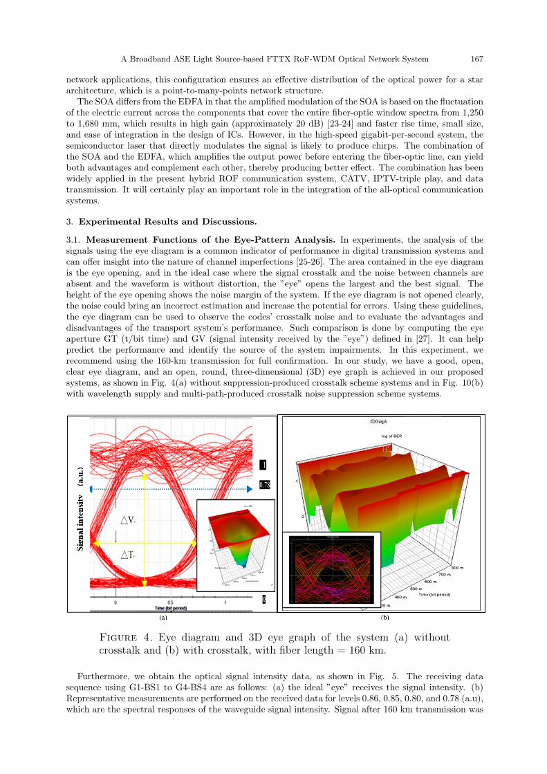
3.1. Measurement Functions of the Eye-Pattern Analysis. In experiments, the analysis of thesignals using the eye diagram is a common indicator of performance in digital transmission systems andcan offer insight into the nature of channel imperfections [25-26]. The area contained in the eye diagramis the eye opening, and in the ideal case where the signal crosstalk and the noise between channels areabsent and the waveform is without distortion, the ”eye” opens the largest and the best signal. Theheight of the eye opening shows the noise margin of the system. If the eye diagram is not opened clearly,the noise could bring an incorrect estimation and increase the potential for errors. Using these guidelines,the eye diagram can be used to observe the codes’ crosstalk noise and to evaluate the advantages anddisadvantages of the transport system’s performance. Such comparison is done by computing the eyeaperture GT (t/bit time) and GV (signal intensity received by the ”eye”) defined in [27]. It can helppredict the performance and identify the source of the system impairments. In this experiment, werecommend using the 160-km transmission for full confirmation. In our study, we have a good, open,clear eye diagram, and an open, round, three-dimensional (3D) eye graph is achieved in our proposedsystems, as shown in Fig. 4(a) without suppression-produced crosstalk scheme systems and in Fig. 10(b)with wavelength supply and multi-path-produced crosstalk noise suppression scheme systems.
Figure 4. Eye diagram and 3D eye graph of the system (a) withoutcrosstalk and (b) with crosstalk, with fiber length = 160 km.
Furthermore, we obtain the optical signal intensity data, as shown in Fig. 5. The receiving datasequence using G1-BS1 to G4-BS4 are as follows: (a) the ideal ”eye” receives the signal intensity. (b)Representative measurements are performed on the received data for levels 0.86, 0.85, 0.80, and 0.78 (a.u),which are the spectral responses of the waveguide signal intensity. Signal after 160 km transmission was

168 S. H. Meng, S.B. Hu, H.C. Chu, C.H. Chang, and S.C. Chu
only losses 0.09 (a.u). These data show that the four received optical signals of the G1-BS1 to G4-BS4have nearly equal intensity. In this experiment, the FTTX ROF-WDM transmission system is very stablewith little loss of optical signal intensity. An ideal, open, clear eye diagram is achieved in our proposedexcellent systems.
Figure 5. Structure of a generic high-speed data communication signal.(a) Ideal judgment eye-received signal intensity. (b) Spectral response ofthe received waveguide eye signal intensity loss.
3.2. Receiver Sensitivity of the BER Quality Factor. The Q-factor from the BER is calculatednumerically by [28]
BER =1
2erfc
( Q√2
)(5)
A commonly used criterion for digital receivers requires the following:
Q(quality)factor ∼= 6, to be above BER ∼= 10−9 (6)
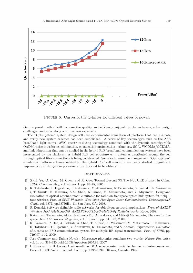
The measured downlink Q factor curves of the sample rate is 10 GHz, the bit rate is 2.5 GBit/s, thesequence length is 128, and the number of samples is 8,192. The non-return-to-zero pulse data signalsfrom CS to BS3 (120-km fiber links) without and with crosstalk are shown in Fig. 6. At Q ∼= 6 for anerror rate of 10−9, the received optical power levels for the -18.8 dBm without crosstalk is Q ∼= 6, andthat with crosstalk is Q ∼= 0. This quality factor value difference yields better communication signalreceive quality performance, results in received optical power reduction, and provides the best sensitivity.
4. Conclusion. We have demonstrated the communication system structure of the integrated RoF sys-tem consisting of OCDMA and WCDMA from the hardware physical layer to the transmission appli-cation layer. The solutions obtained with the integrated RoF-WDM transmission system offer flexibleinterconnections among the simple multi-standards of the platform and increase network capacity. Thehigh-bandwidth and low-loss optical fiber transmission can be used in densely populated cities and metro-politan areas. Simple antennas can be used for transmission in rural areas. These methods will expand thecoverage of mobile broadband, which are the most promising methods to introduce the next-generationintegrated service broadband access network. This method will effectively reduce the complexity and thecost of the system.
The proposed ”enhanced network quality factors with noise interference elimination over hybrid RoFbroadband system” has the potential of achieving more than 160 km of the long-haul microwave fiberlink transmission signal for better broadband communication and transmission service qualities. Thefeasibility of our research is proven by the clear eye diagram and the ”enhanced network quality factor.”
A Broadband ASE Light Source-based FTTX RoF-WDM Optical Network System 169
Figure 6. Curves of the Q-factor for different values of power.
Our proposed method will increase the quality and efficiency enjoyed by the end-users, solve designchallenges, and grow along with business expansion.
The ”Opti-System” system design software experimental simulation of platform that can evaluateand verify new system schemes has been established. A series of key technologies such as the ASEbroadband light source, AWG spectrum-slicing technology combined with the dynamic reconfigurableOADM, noise-interference elimination, equalization optimization technology, SOA, WCDMA/OCDMA,and link adaptation that can be applied in the hybrid RoF broadband communication systems have beeninvestigated by the platform. A hybrid RoF cell structure with antennas distributed around the cellthrough optical fiber connections is being constructed. Some radio resource management ”Opti-System”simulation platform schemes related to the hybrid RoF cell structure are being studied. Significantimprovement in the system performance is expected to be obtained.
REFERENCES
[1] X.-H. Yu, G. Chen, M. Chen, and X. Gao, Toward Beyond 3G:The FUTURE Project in China,IEEE Commun Mag, vol. 43, no. 1, pp. 70–75, 2005.
[2] K. Takahashi, T. Higashino, T. Nakamura, Y. Aburakawa, K.Tsukamoto, S. Kamaki, K. Wakamor-i, T. Suzuki, K. Kazaura, A.M. Shah, K. Omae, M. Matsumota, and Y. Miyamoto, Designandevaluation of optical antenna module suitable for radio-on free-space optics link system for ubiqui-tous wireless, Proc. of SPIE Photonic West 2008 Free-Space Laser Communication TechnologiesXXConf., vol. 6877, pp.68770H1–11, San Jose, CA, 2008.
[3] S. Komaki, Software definable radio networks for ubiquitous network applications, Proc. of ASTAPWireless JEG (MMCSEG)9, ASTAP08-FR14-EG-MMCS-04 RadioNetworks, Kobe, 2008.
[4] Katsutoshi Tsukamoto, Akira Hashimoto,Yuji Aburakawa, and Mitsuji Matsumoto, The case for freespace, IEEE Microwave Magazine, vol. 10, no. 5, pp. 84 – 92, 2009.
[5] K. Kazaura, P. Dat, A. Bekkali, A. Shah, T. Suzuki, K. Wakumori, M. Matsumoto, T. Nakamura,K. Takahashi, T. Higashino, Y. Aburakawa, K. Tsukomoto, and S. Komaki, Experimental evaluationof a radio-on-FSO communication system for multiple RF signal transmission, Proc. of SPIE, pp.719907–1-12, 2009.
[6] Jose Capmany and Dalma Novak , Microwave photonics combines two worlds, Nature Photonics,vol. 1, pp. 319–330 doi:10.1038/nphoton.2007.89, 2007.
[7] I. Rivas and L. B. Lopes, A microcellular DCA scheme using variable channel exclusion zones, emProc. of IEEE Vehic. Technol. Conf., pp. 1395–1399, Ottawa, Canada, 1998.

170 S. H. Meng, S.B. Hu, H.C. Chu, C.H. Chang, and S.C. Chu
[8] A. Casini and P. Faccin, Analog Laser Predistortion for Multiservice Radio-Over-Fiber Systems, emProc. of IEEE Int. Topical Meeting Microwave Photon, pp. 123–128, Budapest, Hungary, 2003.
[9] B. J. Offrein, F. Horst, G. L. Bona, R. Germann, H. W. M. Salemink, and R. Beyeler, AdaptiveGain Equalizer in High-Index-Contrast SiON Technology, em IEEE Photon Tech Lett., vol. 12, no.5, 2000.
[10] C. H. Chang, H. H. Lu, H. S. Su, C. L. Shih, and K. J. Chen, A Broadband ASE Light Source-BasedFull-Duplex FTTX/ROF Transport Systems, em Opt Express, vol. 17, pp. 22246–22253, 2009.
[11] C.Y. Li, H. C. Peng, W. Y. Lin, H.S. Su, S.H. Meng, and H.H. Lu, Full-duplex ROF TransportSystems Based on Broadband ASE Light Source and Nonlinear Distortions Suppression Scheme, emIEEE OECC. Lett., vol. 14, pp. 1–2, 2009.
[12] S.H. Meng, Jen-Fa Huang, Ke-Jen Hu, and An-Chi Huang, Employing Broadband Light Source onFTTx/RoF Transmission System, em IEEE 3CA, vol.1, pp. 438–441, 2010.
[13] J. S. Lee, Y. C. Chung, and D. J. DiGiovanni, Spectrum-sliced Fber Ampli?er Light Source forMultichannel WDM Applications, em IEEE Photon. Technol. Lett., vol. 5, no. 12, pp. 1458–1461,1993.
[14] K. Akimoto, J. Kani, M. Teshima, and K. Iwatsuki, Gigabit WDM-PON System Using Spectrum-slicing Technologies, em Proc. of the 29th European Conf Opt Comm (ECOC2003), IEEE, paperTh2.4.6, 2003.
[15] K. Iwatsuki, J.-i. Kani, H. Suzuki, and M. Fujiwara, Access and Metro Networks Based on WDMTechnologies, em J. Lightwave Technol, vol. 22, no. 11, pp. 2623–2630 , 2004.
[16] S. Kaneko, J. Kani, K. Iwatsuki, A. Ohki, M. Sugo, and S. Kamei, Scalability of Spectrum SlicedDWDM Transmission and Its Expansion Using Forward Error Correction, em J. Lightwave Technol.,vol. 24, pp. 1295–1301, 2006.
[17] M. K. Smit and C. Van Dam, PHASAR-based WDM-devices: Principles, Design and Applications,em IEEE J. Sel. Top. Quantum Electron., vol. 2, no. 2, pp. 236–250, 1996.
[18] M. Vasilyev, I. Tomkos, M. Mehendale, J.-K. Rhee, A. Kobyakov, M. Ajgaonkar, S. Tsuda, and M.Sharma, Transparent Ultra-Long-Haul DWDM NetworksWith ’Broadcast-and-Select’ OADM/OXCArchitecture, em J. Lightw. Technol., vol. 21, no. 11, 2003.
[19] K. Okamoto, M. Okuno, A. Himeno, and Y. Ohmori, 16 Channel Optical Add/drop MultiplexerConsisting of Arrayed Waveguide Gratings and Double Gate Switches, em IEEE Photon. Lett., vol.32, no. 1471, 1996.
[20] H. S. Chung, S. H. Chang, and K. Kim, Experimental Demonstration of Layer-1 Multicast for WDMNetworks Using Reconfigurable OADM, em Opt. Fiber Technol., vol. 15, pp. 431–437, 2009.
[21] G.P. Agrawal, em Fiber-Optic Communication Systems, second edition, City, State: Joinery & Sons,Inc, 1997.
[22] J. Lee, Y. C Chung, and D. J. DiGiovanni, Spectrum-sliced Fiber Amplifier Light Source for Multi-channel WDM Applications, em IEEE Photon. Technol. Let., vol. 5, no.12, 1993.
[23] F. Koyama, T. Yamatoya, and K. Iga, Highly gain-saturated GaInAsP/InP SOA modulator forincoherent spectrum-sliced light source, em Proc. of Conf. Indium Phosphide and Related Materials,pp. 439–442, Williamsburg, VA, 2000,.
[24] A. J. Keating and D. D. Sampson, Reduction of Excess Intensity Noise in Spectrum-sliced IncoherentLight for WDM Applications, em J. Lightw. Technol., vol. 15, no. 1, pp. 53–61, 1997.
[25] Jerry Seams, em A Comparison of Resistive Terminators for High Speed Digital Data Transmission,High Frequency Electron., 2005.
[26] Gary Breed, Analyzing Signals Using the Eye Diagram, em High Frequency Electron., 2005.[27] I gor S. Stievano, Ivan A. Maio, Flavio G. Canavero, and Claudio Siviero, Reliable Eye-Diagram
Analysis of Data Links via Device Macromodels, em IEEE Transac. Advanced Packaging, vol. 29no. 1, 2006.
[28] G.P. Agrawal, em Fiber Optic Communication Systems, New York, NY: John Wiley & Sons, 1997.