a breakaway concept for timber utility poles
TRANSCRIPT

A BREAKAWAY CONCEPT FOR TIMBER UTILITY POLES G. K. Wolfe, M. E. Bronstad, and J. D. Michie, Southwest Research Institute; and J. Wong, Insurance Institute for Highway Safety
The feasibility of modifying existing timber utility poles so that they will readily break away upon impact was investigated. Various drilled holes and groove patterns were experimentally examined during 13 pendulum tests of full-size class 4-40 poles by using a 4,000-lbm (1814-kg) mass striking the specimens at 20 mph (32 km/h). Two weakened zones, located 6 in. (152 mm) above grade and 6 ft (1.8 m) from the pole top, facilitated the detachment of the 27-ft (8.2-m) center section. Based on Federal Highway Administration criteria [400 16· s (1780 N• s) for pendulum tests J, linear impulse test results of weakened and unweakened poles indicate that poles with a large probability of being struck by an errant vehicle may be easily modified to a breakaway structure . Vehicle crash tests are recommended as the next step in breakaway concept development.
•ROADSIDE STRUCTURES that readily break away when impacted by an errant vehicle have been used for several years. Roadside sign structures (1) and lighting supports (2) have been of breakaway design since mid-1960, and their Worth has been clearly demonstrated by the reduction in injuries and fatalities in highway accidents involving them. In general, these breakaway structures employ a weakened shear plane located near grade level. Designs such as a three- or four-bolt slip base or a frangible aluminum base member readily disengage or fracture when impacted by a vehicle yet have adequate strength to resist sign or luminaire environmental loads. The design criteria for these structures require that (a) they disengage during vehicle impact without producing hazardous forces in the car and (b) the broken parts and elements not present a hazard to vehicle occupants or other traffic. That is, the pole should break easily and should be thrown clear of the impacting car and other traffic.
CONCEPT
When the breakaway concept is applied to timber poles, one of the self-imposed constraints is to develop a scheme whereby existing as well as new poles can be easily and economically modified in the field. Furthermore, because poles are connected by lines to adjacent poles, a second weakened zone is required immediately below these lines so that the center section of the pole will detach from the top, line-carrying section. This approach minimizes the weight supported by the adjacent poles after a collision and hence minimizes the possibility of broken lines and loss of electrical or communication service.
The method used in this program to effect a weakened zone in the timber specimens is to drill and cut a pattern of holes and grooves at two selected elevations (3). This approach can be accomplished in actual service by maintenance personnel uSing standard equipment. A possible drawback of this method is that the integrity of the preservative treatment may be violated in mosl modifications, leaving the pole vulnerable to rot. However, field application of preservatives offers protection.
64

65
TEST PROGRAM
The program objective was to determine the technical feasibility of modifying timber utility poles so that they will break away when impacted by errant vehicles with minimum injuries to passengers while maintaining a high degree of structural integrity to sustain service loads under design environmental conditions. The FHWA linear impulse value of 400 lb•s (1780 N• s) for luminaire supports tested by a pendulum was selected as the evaluation criterion for this program ( 4).
The program consisted of a series of 13 pendulum impact tests of timber poles and pole assemblies of a typical pole configuration. Initial effort was concentrated on effecting a fracture near grade level (phase I), and then attention was directed to poles modified for both top and bottom fracture planes (phase II). For comparison, a baseline test was conducted on an unmodified pole. Experimental procedures are presented in the Appendix.
FINDINGS
Typical Utility Pole
There is a wide range in physical properties of existing timber utility poles. Basically, poles are categorized into nine general classes with each class having an average of 12 lengths. In addition, there are seven wood species and five preservative treatments. Hence, there is a possibility of nearly 3,800 unique combinations of these features (i.e., 9 x 12 x 7 x 5). For this program, a representative utility pole was defined for use as a model in evaluating the feasibility of the breakaway concept. To define this model, we selected the most predominant characteristics of existing poles by surveying telephone and other utility companies. Electric power (utility) companies prefer classes 2, 3, and 4 poles, whereas telephone companies use more class 4 and class 5 poles. Because 80 percent or more of the telephone company poles are used jointly with a utility company, class 4 is the most common group. The length most often specified is 40 ft (12.2 m) with 34 ft (10.4 m) extending above grade and a 6-ft (1.8-m) embedment. A description of the model utility pole used for all of the tests is given below.
Characteristic
Species Class Stress Minimum circumference
At 6 ft (1.83 m) from butt end At top
Length Surface treatment
Lower Pole Break Zone (Phase I)
Value
Southern yellow pine fiber 4 8,000 psi (55 MPa)
33.5 in. (0.85 m) 21 in. (0.5 m) 40 ft (12.2 m) 10-lbm (4.53-kg) creosote
A breakaway section height of 6 in. (152 mm) above grade was selected because it would provide undercarriage clearance for virtually all standard cars and still have sufficient length above grade to attach the equipment to modify the poles without excessive excavation.
As a starting point for the lower break zones, one 35/s-in. (92-mm) diameter hole was drilled through the pole 6 in. above grade; the hole axis was approximately 90 deg to the pendulum velocity vector. This hole configuration was selected after work performed by the California Division of Highways (4) on timber sign posts. Linear impulse results of the first test (Table 1) and test2, 5-in. (12.7-cm) diameter hole of 798 (3550) and 980 lb·s (4359 N·s) respectively, showed that the single-hole pattern would not satisfy the 400-lb·s (1779-N• s) requirement.
After tests 1 and 2, there was concern about whether the utility pole could be modified to break within the 400-lb·s (80-N· s) linear impulse region. This concern was
66
based on the fact t11at a class 4-40 pole weighs almost 1,000 lbm (450 kg), and the linear impul1>e rl:l4ul.n::u jusl to accelerate the pole to impact speed could possibly exceed 400 lb·s. Test 3, therefore , was conducted to experimentally ascertain the impulse required to accelerate the pole. Pole NP-1 was used with the lower fractured section removed. The pole was held in a vertical position by an overhead crane so that it rested on but was not embedded in the ground. In this configuration, there was no fracture energy expended during impact and momentum was transferred Irom the pendulum mass to the pole. The momentum change for this test serves as a lower bound for modified class 4-40 poles. As shown in Table 1, the maxim.um recorded acceleration was 7. 6 g· linear impulse was 151.5 lb·s (673. 9 N• s) well below the 400-lb·s guideline.
As an alternate method to improve the pole fracture characteristics, two holes were drilled through the pole and oriented 90 deg apart (Fig. 1). Theoretically, the two-hole pattern presents a constant section modulus regardless of impact orientation . This layout r emoved material needed to reduce the shear area while providing the maxi.mum section modulus for bending strength required for line loads. Tests 4 through 6 were conducted to examine this hole pattern. As shown in Table 2, linear impulse values ranged from a low of 304 (1352) to a high of 612 lb·s (2722 N· s) for the three tests; because these values were close to the target value of 400 lb•s, we decided to proceed to phase II experimentation.
Modified Pole Evaluation (Phase II)
In phase Il pole specimens were evaluated as a part of a utility line system. That is, a three-pole utility line was erected with the center pole being the specimen; line tension was adjusted to 190 lbf (845 N) (normal installation tension) for the four-line configuration. An upper breakaway zone similar in design to the lower zone (i.e., two holes spaced 90 deg apart) was located 6 ft (1.8 m) from the top of the pole. The hole diameter was scaled down from 3% (89) to 2 in. (51 mm) based on sectional areas of the pole specimen at the lowe1· and upper points.
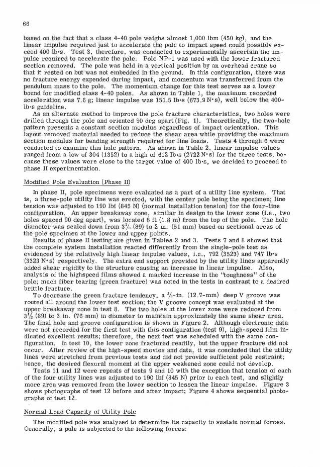
Results of phase II testing are given in Tables 2 and 3. Tests 7 and 8 showed that the complete system installation reacted diffe1·ently from the single-pole test as evidenced by the relatively high linear impulse values i.e. 792 (3523) and 747 lb ·s (3323 N• s) respectively. The extra end s upport provided by the utility lines apparently added shear rigidity to the structure causing an increase in linear impulse. Also analysis of tbe highspeed films showed a marked increase in the "toughness" of the pole; much fiber tearing (green fractu1·e) was noted in the tests in conti·ast to a desired brittle fracture.
To decrease the green fracture tendency, a %-in. (12.7-mm) deep V groove was routed all around the lower test section· the V groove concept was evaluated at the upper breakaway zone in test 8. The two holes at the lower zone were reduced from 3% (89) to 3 in.. (76 mm) In diameter to maintain i:lJ:Jproxima:tely the same shear area. The final hole and groove configuration is shown in F igure 2. Although electronic data were not recorded for the fil·st test with this configuration (test 9) high-speed film indicated excellent results; therefore, the next test was scheduled with the same configuration. In test 10 the lower zone fractured readily, but the upper fracture did not occur. After review of the high-speed movies and data, it was concluded that the utility lines were stretched from previous tests and did not provide sufficient pole restraint; hence , the desired flexural moment at the upper weakened zone could not develop.
Tests 11 and 12 were repeats of tests 9 and 10 with the exception that tension of each of the four utility lines was adjusted to 190 lbf (845 N) prior tu each test, and slightly more area was removed from the lower section to lessen the linear impulse. Figure 3 shows photographs of test 12 before and after impact; Figure 4 shows sequential photographs of test 12.
Normal Load Capacity of Utility Pole
The modified pole was analyzed to determine its capacity to sustain normal forces. Generally, a pole is subjected to the following forces:

Table 1. Phase I test data summary.
Moment of
Test Inertia Sec- Maxi-Sec- About ti on Impact mum Linear Final Impact Frac• Aver-ti on X-Y Mod- Ve- Accel- Im · Ve- Dura- tu re Peak age
Specj- Area Axis ulus locity eration pulse locity lion Energy Force Force Test Description (in. 2
) (in.') (In.') (It/sec) (g) (lb·s) (fps) (msec) ([t-lb) (!bf) (lb!) Comments
NP-I Single 3.62-in. diam- 52.46 286 53.0 30 12.3 796 23.57 62.3 21,400 49,100 12, 620 eter hole through at 6 in. above ground-line oriented 90 deg to impact
NP-2 Single 5-in. diameter 44.17 202 35.6 30 14.2 960 22.11 76.4 25, 500 56, 800 12, 610 hole through at same location as NP-I
NP-IA Fractured section of 30 7.6 152 26.76 16.0 4,540" 30,350 9,655 Test used to deter-NP-1 cut off, and mine lower limit pole suspended just of impulse obtain-touching ground able
NP-4 Two 3.62-in. diam- 31.50 316 56.3 30 9.6 304 27.55 31.4 8, 750 39, 350 9,684 eter holes oriented 90 deg apart located 6 in. above ground level
NP-5 Same as NP-4 29.43 287 51.6 30 10.5 612 25.07 85.5 16,950 42,000 7,201 Specimen appeared to lift out of sand at impact
NP-6 Same as NP-4 32.03 326 57.5 30 11.7 466 26.24 39.2 13,100 46,600 11, 684
"Inertial energy ,
Figure 1. Two·hole breakaway po le concept. ""ll.lJ. •
Table 2. Description of specimens for phase 11 testing.
Section A-A ====
I
Diameter Througt1 (Typical) I
3 112 n.
·H+'b--1 ~-+Hl+t8.9 f ITll x l+H-tt--'--1111111------r-l 1 I A
6 in. 115.2 cm)
Ground Lev•?I
~""~~•~u '
Test
7
10 11
12 13
Specimen
NP-7
NP-8
NP-10
NP-11 NP-14
NP - 12 NP • l3
Description
Pole 1
Two 3. 62-in. diameter holes drilled 90 deg apart at 6.5 It from butt
Same as NP-7
Two 3-in. holes oriented 90 deg apart at 6.5 ct from butt plus Y:-in. deop V groove all arnund
Same as NP-10 Same as NP-10 except holes are 3"X: in, in
diameter Same as NP-14 No weakened section
Pole 2
Single 3. 62-in. diameter hole through at 6 rt from top
Two 2-in. diameter holes 6 rt from top plus "X:-in. deep groove cut all around at test section
Same as NP-B
Same as NP-10 Same as NP-10
Same as NP-14 No weakened section
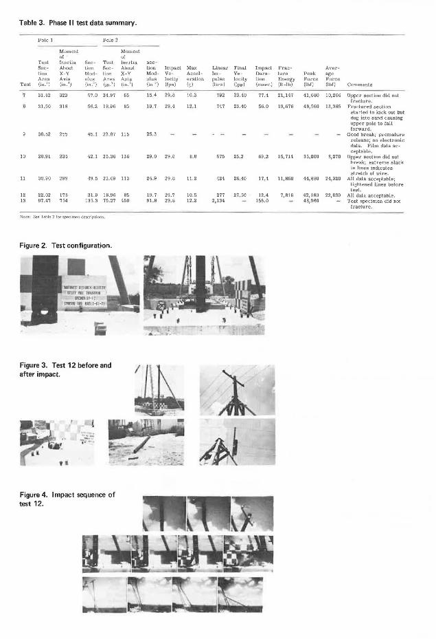
Table 3. Phase 11 test data summary.
Pole 1 Pole 2
Moment of
Test Inertia Sec- Test Sec - About ti on Sec-ti on X-Y Mod- ti on Area Axis ulus Area
Test (in. 2) (in.") (in.~) (in. 2
)
'I 31.82 323 57.0 24.97
31 , 50 318 56.2 18.96
30. 52 255 45.l 22.87
10 28.91 235 42.1 25.36
11 30.90 299 49.5 22.69
12 22.02 17B 31.9 18.96 13 97.47 754 135.3 75.27
Note: See Table 2 for specimen descripti ons.
Figure 2. Test configuration.
Figure 3. Test 12 before and after impact.
Figure 4. Impact sequence of test 12.
Moment of lnerha About X-Y Axis (in.')
65
85
115
136
113
85 450
~ec-
ti on Impact Mod- Ve-ulus locity (in') (fpR)
15.4 29.8
19,7 29.4
25.3
29.0 29.8
24 9 29.8
19. 7 29.7 91.B 29.8
Max Linear Final Impact Frac- Aver-Accel- Im- Ve- Dura- ture Peak age eration pulse locity lion Energy Force Force (~) (lh·s) {[ps) (msec) (rt-lb) (lbf) (lbf) Comments
10.3 792 23.40 77.4 21, 147 41,080 10,266 Upper section did not fracture.
12. 1 747 23.40 56.0 19,676 4B, 560 13,385 Fractured section started to kick out but dug into sand causing upper pole to Call forward&
Good break; premature release; no electronic data. Film data ac-ceptable,
8.8 575 25.2 69,2 15, 714 35,000 8,270 Upper section did not break; extreme slack in lines indicates stretch of wire.
11.2 424 26.40 17.4 11,868 44, 880 24,320 All data acceptable; tightened lines before test .
10.5 277 27. 50 12.4 7,816 42,160 22,039 All data acceptable. 12.2 2, 134 155.0 48,960 Test specimen did not
fracture.

69
1. Vertical forces due to weight of pole, wires, ice., and downward pull of guys; 2. Lateral horizontal forces due to wind across line on pole and wire; 3. Longitudinal horizontal forces due to unbalanced pull of wires; and 4. Torsional forces due to unbalanced pull of wires.
A pole is strong in respect to the vertical forces but weak for horizontal forces, and the cross arms are weak for the torsional forces (5, 6, 7). fu practice, calculations for strength of poles are ordinarily limited to the effects-of side wind.
Minimum section moduli of poles located in the three territorial divisions of the United states were determined. The findings show that a class 4-40 pole, embedded 6 ft in the ground with characteristics of the model pole, requires a minimum section modulus of 32.4 in. 3 (531 cm3
) for the most severe environmental loading areas. Because the maximum section modulus for the breakaway concept is approximately 50 in. 3
(819 cm3), it is apparent that the modified pole can support its normal load in any
region in the United states.
DISCUSSION OF RESULTS
Concept Performance
Results of pendulum tests are shown in Figure 5 in the form of linear impulse versus shear area of the lower test section. Phase I tests 1, 2, 4, 5, and 6 were performed on pole specimens that were unrestrained or not loaded by service lines; results are indicated by open circles. The origin point (i.e., zero shear area) was determined in test 3 by impacting a detached but suspended pole segment; the linear impulse measured in this case is that required to accelerate the pole segment to pendulum mass speed.
fu phase II tests, the pole specimens were under typical service line restraints and loads; results are shown in Figure 5 by squares. The importance of the groove cut around the test pole is illustrated by comparing tests 7 and 8 (ungrooved specimens) with tests 10, 11, 12, and 14 (grooved specimens). Although insufficient testing was performed to quantify the curves, two definite trends are shown in Figure 5. From this evidence, it seems apparent that shear area alone is an insufficient parameter to control the fracture mechanism; the geometry of the weakened section including stress risers such as grooves is also a prime factor.
As might be expected, there was a marked change in fracture mechanism between the single-pole tests (phase I) and the system tests (phase II). Principally the simulated lines in phase II tests introduced a vertical load in the test specimen. More importantly, these lines provided considerable constraint at the pole top. From analysis of high-speed movies, this constraint approximated a rigid fixity, at least instantaneously, from the cross-arm connection down to the single-wire connection. Flexural loads due to this constraint were introduced in the upper weakened section after the lower section had sheared. This sequence is shown in Figure 6. fu one test (test 10), the utility lines were atypically slack and did not provide the necessary fixity; hence, the upper section failed to break.
As indicated in Figure 5, a net shear area of approximately 30 in. 2 (190 cm2), with
proper consideration of geometry, appears to constitute an adequate design of a lower weakened section for the breakaway timber utility pole concept; however, this finding should be investigated with vehicle crash tests before a finalized value is established.
Concept Practicality
The primary objective of the program was to determine whether a typical timber utility pole could be modified so that it would break away upon vehicle impact such that the occupants could survive, preferably uninjured. Obviously, for the scheme to be practical, the modified pole must sustain surface loads (i.e., wind, ice, etc.). As presented in the findings a class 4- 40 pole geometry must be reduced to a section area of 30 in. 2 or less at the lower break section in order to limit the breaking linear impulse to 400 lb•s (80 N•s) or less. When the pole section modulus required to support wind, ice, and dead load from the four utility lines was calculated, it was determined that a section modulus of 32.4 in. 3 (5447 cm3
) was sufficient. Linear impulse values of

70
the pendulum tests are shown in Figure 7 as a function of section modulus of the modified poles. Also shown are the FHWA linear impulse recommenda.tion and the minimum section modulus requirement for normal loads. It can be seen that a section modulus "window" exists from 32 to 50 in.3 (524 to 819 cm3
) where the functions of both breakaway and normal load-supporting capabilities are met.
It should be emphasized that the findings of this program are applicable to one particular timber utility pole: a class 4-40, creosote-treated southern pine with a 6-ft (l.8-m) cross arm and four lines. However, it is believed that the concept is applicable to a large percentage of all timber poles.
CONCLUSIONS
1. The concept of modifying a timber utility pole so that it breaks away upon vehicle impact without subjecting vehicle occupants to undue hazard appears technically feasible. Furthermore, the suggested modification can be easily performed by routine equipment and personnel and, hence, is economically attractive.
2. A class 4-40 timber utility pole, typical of poles found in service today, is converted to a breakaway structure by reducing the lower break zone to a sectional area of approximately 30 in. 2 (190 cm2
) by means of two drilled holes intersecting at 90 deg at the pole center and a %-in. (13-mm) groove cut around the pole perimeter. The %in. groove appears to change the break from a high-energy "green" fracture to a lowenergy brittle fracture.
3. A center section of the class 4-40 pole can be made to detach from the upper pole by providing a second weakened zone immediately below the bottom utility line connection; hence, adjacent poles and lines are required to support only the top section of the detached pole. The upper weakened section is similar to the lower section but scaled according to a ratio of pole diameters. Because the upper break involves a flexure mechanism, the utility lines must be sufficiently taut, say 190-lbf (845-N) tension, to provide an end fixity restraint that in turn induces the failure moment.
4. The breakaway modification reduces the normal load capacity of a utility pole. Under conditions of high winds or icing, failure may occur at one or both weakened sections, although design calculations indicate that the modified pole is adequate for these loads. It would seem reasonable that only a selected number of the most vulnerable poles are candidates for modification.
5. The probability of a severe injury or fatality is almost certain in a carunmodified pole crash for unrestrained occupants even for impact speeds as low as 15 mph (24 km/h), whereas the potential hazard to other traffic from the detached pole missile from a modified system is problematical.
6. Finally, it is recognized that, although the breakaway timber utility pole concept appears feasible from a technical and practical viewpoint, the investigation has proceeded through only the first of two or more steps. Before the concept is validated for in-service trial use, vehicle crash tests should be conducled Lu demonstrate concept performance under actual conditions.
REFERENCES
1. Olson, R. M., Rowan, N. J., and Edwards, T. C. Break-Away Components Produce Safer Roadside Signs. Highway Research Record 174, 1967.
2. Edwards, T. C., Martinez, J. E .. and Ross, H. E., Jr. Development of Design Criteria for Safety Luminaire Supports. NCHRP Rept. 77, 1969.
3. Tamanini, F. J. Designing Fail-Safe 81:ructures for Highway Safety. Federal Highway Administration, 1970.
4. Nordlin, E. F., Ames, W. H., and Field, R. N. Dynamic Tests of Wood Post and Timber Post Supports for Roadside Signs-Series XV. California Division of Highways, Rept. M&R 636398, Dec. 1967.
5. Pender, H., and Del Mar, W. Electrical Engineers' Handbook: Electrical Power, Fourth Ed. John Wiley, New York, 1949.
6. Abbett, R. W., American Civil Engineering Practice, Vol. II. John Wiley, New York, 1956.

Figure 5. Linear impulse versus shear area.
Figure 6. Utility pole fracture sequence: (a) before impact, (b) lower section fracture, and (c) complete fracture.
Figure 7. Linear impulse versus section modulus.
:ll.
1000
900
800
700
600
500
g_ 400 E
ill c: :.J 300
200
100
20
10 ~
~ B 0
~ :ll. 6 :; c. .§
ill 4
c :.J
3
0
I
0
/ "#2 L ~~'tt1 /#1
I~ #8 / -#5/~ / .
Ungroovec Phase 11 - #10 !'--Grooved Phase II Soecimens / / Soecimen...i_
I/ ~ 1
/ / / 0#4 v • #12
/' / ,,
//" # 3
10 20 30 Shear Area, in.2
(a) ~ (b)
: :
20 40 60 BO
Section Modulus, in.3
40
FHWA Criterion--1_
6Test#3-Specimen NP·1A QPhase I Tests
Phase 11 Tests:
0 Ungrooved • Grooved
50
Grooved Specimens
Ungrooved Specimens
60
Pole Strength Insufficient for Wind Loads
Design Envelope
Pole Strength Excessive for Breakaway Design
100 120
70
140

72
7. Pender, H., and Mcilwain, K. Electrical Engineers' Handbook: Communication F.lectronicf', Fourth F.d. .Tohn Wiley, New York, 1950.
APPENDIX EXPERIMENTAL PROCEDURES
The facility consists of a pendulum, operating equipment, and test control and data acquisition instrumentation. An overall view of the facility is shown in Figure 8. A 4,000-lbm (1800-kg) mass is suspended in such a manner that it remains horizontal throughout the normal swing arc of 26-ft (7.92-m) radius and strikes the specimen 20 in. (0.5 m) above grade. The 3- x 6- x 1. 5-ft (0.9- x 1.8- x 0.4-m) mass is faced with a steel bumper fabricated from 8-in. (203-mm) diameter extra heavy pipe and filled with concrete. A 1-in. (25-mm) thick, 70 durometer neoprene pad attached to the steel bumper provides the impact surface of the mass.
Impact velocity is programmed by adjusting the vertical fall of the mass, and it is calculated by the expression
where
V 1 = impact velocity, g = acceleration due to gravity, and h = mass drop height.
Impact velocities ranging from 0 to 40 fps (0 to 12.19 m/s) are obtainable within the available 25-ft (7 .62-m) drop height.
Test specimens are stationed at the lowest point of the pendulum arc where the kinetic energy (i.e., velocity) of the mass is a maximum. The specimens were inserted 6 ft (1.8 m) into a 24-in. (0.6-m) diameter steel-cased hole. A damp, uniformly graded sand was then tamped into the void between the pole and casing.
Mechanics of the test were simple. Instrumentation systems were energized and calibrated. The mass was pulled away from the impact point until its elevation provided the proper drop height. On signal from the test engineer, the mass was released by means of a quick-release mechanism.
Signals from an accelerometer, mounted at the rear of the mass, were continuously recorded throughout impact by a high-speed magnetic tape recorder operating at 60 in./s (1.5 m/s). The recorded data were later replayed through an oscillograph without electronic filters at various tape deck and oscillograph speeds. Frequency response of the system, as determined by the M-400 oscillograph galvanometer, was 0 to 240 Hz. A typical data trace is shown in Figure 9. The accelerometers were subjected to a calibrated 2.8-g, 100-Hz acceleration before and after each test; the recorded signal served as a calibration standard for data processing. Signals from a break-wire speed trap provided impact velocity data.
High-speed cameras were used to record events on 16-mm color film. A Red LakeHYCAM 400-ft (122-m) x 16-mm high-speed camera operating at 1,000 fps (305 m/s) recorded the events. A timing pulse of 60 pps was recorded on the film edge and used to establish the exact camera frame rate.
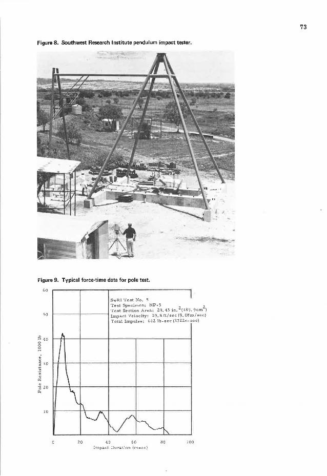
Figure 8. Southwest Research Institute pendulum impact tester.
Figure 9. Typical force-time data for pole test.
60
50
~ 40 0 0 0 ~
JO
J
I
\ \~
SwRI Test No. 5 I
Test Specimen: NP-5 Test Section Area: 29. 43 in. 2 ( 189. 9cm
2)
rn/sec) ec)
Impact Velocity: 29. 8 ft/sec (9. 08
Total Impulse: 612 lb-sec (2722n-s
~ v ~ I'. 20 40 60 80 100
Impact Duration (msec)
73

74
DISCUSSION
John M . .Peacock, American Telephone and Telegraph Company
The paper presents the results of analysis and preliminary tests to evaluate the feasibility of field modifications to existing timber utility poles to convert them into structures that would readily break away on impact. The authors suggest that, pending further evaluation and testing, this may be a practical means of reducing roadside hazards.
There can be no responsible argument against the need to minimize roadside hazards, particularly those structures in vulnerable locations. Weakening selected utility poles by removing material, as suggested, may indeed be feasible in some cases, but the resultant reduced load-carrying capacity would have to be evaluated very carefully in each case. The authors state that the cross-sectional area and section modulus of a class 4- 40 pole can be reduced by factors more than three to one and that the pole will still support wind, ice, and dead load "for the most severe environmental loading areas." They further state that the concept is applicable to a large percentage of all timber poles. This implies a very generous factor of safety for the typical pole. Our experience with the design and performance of pole lines in the Bell System would not support such conclusions.
Design calculations on pole lines take into account the strength of the various poles (after aging) and also depend on assumptions on loading. Normal loads include not only dead loads, wind, and ice as referenced in the paper, but many other dynamic loads such as craftsmen's ladders and platforms, "cable dancing" (because of aerodynamic instability), and shock loads. Abnormal loads can be almost anything that nature can muster. Experience with pole line design practices over the years indicates that factors of safety are small under heavy loading conditions and inadequate to cover extreme storm loading that can and does occur from time to time in many areas of the country.
Recent history in Southwestern Bell provides a dramatic illustration. On December 3, 1973, an unexpected ice storm hit, accompanied by 50-mph (80-km/h) north winds. The storm cut a 100-mile (160-km) wide swath from southwest to north central Kansas. In its wake it left more than 5,700 poles down and 27,500 miles (44 250 km) of wire affected. In a case such as this, the poles typically go down in a "domino" pattern. One pole fails, subjecting the adjacent poles to abnormal loads and shock; then they fail, and so on down the line. Thus even an occasional weakened pole could trigger an extensive collapse, particularly under storm loading. Potential safety hazards to the general public and to the utility workmen are obvious, particularly in the common situation where power and telephone companies are sharing the same pole.
The December storm was a multimillion dollar emergency repair job for Southwestern Bell, but more important were the consequences of service disruption (power as well as telephone) to the public at a time of emergency. About 34,000 phones were out of service, and 152 towns were isolated from the long distance network. About 45 percent of the poles in the storm area survived this disaster. It must be expected that virtually none would have remained if many of them had been intentionally weakened by a factor approaching 3 to 1.
The Bell System has had vigorous policies for the construction of below-ground plants since the 1950s. To the extent that economic resources permit, we are advocating to our Associated Operating Companies the continued implementation of this policy so as to phase out aerial plants wherever possible at the earliest date. Diversion of available funds to any large-scale modification of the existing aerial plant could only slow progress. We issued a letter to the Bell Companies early in 1973 to this effect. The following brief quote from this letter will summarize our position:
Our recommendation is to vigorously proceed with our present policy of undergrounding:
1. Use below ground construction as a first choice in all new construction. 2. Replace existing aerial plant with out-of-sight plant whenever feasible
in connection with plant relocation work, relief jobs, etc. It is important that we remove aerial plant wherever it is practical to do so.

3. In plant inspection work, and other quality survey activity, be sure that your forces identify pole lines and, in particular, individual poles that are in hazardous locations. The highest priority should be given to their relocation, or preferably to their removal. This same philosophy obviously applies to the placement of any new poles.
We feel that this program will achieve the objective but avoid wasteful expenditures and resultant excessive revenue requirements. Through its undergrounding program, the Bell System has been able to reduce its inventory of owned poles to 19 million in 1972. This number is now decreasing at a rate of Y, million per year, and may be expected to decrease even faster in the future.
H. A. Onishi, Commonwealth Edison Company, Maywood, Illinois
75
The authors propose to drill holes through the pole and to cut V grooves around the circumference to facilitate the breakaway concept. This concept appears to have two serious flaws:
1. The fiber content of the pole has been reduced to such an extent that the pole does not meet the strength requirements of the National Electric Code for the highdensity loads common to the Commonwealth Edison Company. This situation is further compounded by the large number of poles that are shared jointly with the telephone company.
2. The proposed method of providing weakened sections of pole exposes heartwood that can only be superficially protected from decay by supplementary preservative treatment.
The paper states that a class 4- 40 pole requires a minimum section modulus of 32.4 in. 3 (531 cm3
) for the most severe environmental loading areas. It also states that a section modulus "window" exists from 32 to 50 in.3 (525 to 820 cm3
) where the functions of both breakaway and normal load-supporting capabilities are met. Not stated were the conductor sizes and span lengths used when the tests were made. The 32- to 50-in. 3 section modulus range would not meet load-supporting requirements of the Commonwealth Edison Company. The appendix shows that calculations for required section modulus of a class 4-40 pole with four commonly used Edison conductors is a minimum of 54.6 in. 3 (8 95 cm3
). Inasmuch as we frequently share the t:iole with the telephone company, the addition of a typical telephone cable changes the required section modulus to 67. 7 in.3 (1110 cm3
). These figures are with a minimum factor of s afety of 2 per the 6th edition .of the National Electric Code (ANSI C2.2). Higher voltage lines could require a grade B construction and a factor of safety of 4, further increasing the required section modulus.
For a fuller examination of the effect of reducing the strength of the pole, Table 4 gives the minimum section modulus for various classes of an uncut 40-ft (12 .2-m) pole, both at the groundline and at the proposed weakened section 6 in. (152 mm) above the groundline. Also listed is the proposed weakened section modulus.
This table clearly illustrates the consequence of providing a weakened section in the pole. In effect the pole class is reduced to about the equivalent of a class 9 pole. As an economic consideration, we would be buying and installing a class 4 pole and only obtaining the benefits of a class 9 pole.
Comm9nwealth Edison Company has approximately 1,500,000 poles in plant. In 1973 we set 29,000 poles of which 44 percent were either (a) class 4 poles taller than 40 ft or (b) 30-ft and taller poles of class 2, 1, or H-1. These poles all have a greater section modulus than a 4-40 pole. It is obvious that the load-supporting requirements of these taller and/or larger poles would not be met if the section modulus were reduced to the range of 32.4 to 50 in. 3
•
We question the adequacy of the test setup to simulate actual utility lines. A more typical test line would consist of at least five poles, all of which have been weakened by drilling of holes and cutting of V grooves. Then, when impact testing is conducted on the middle pole, the possibility of cascading failures to adjacent weakened poles can be observed.

76
Table 4. Minimum section moduli for various pole Slight angles in the pole line, vertical loadine; of poles duP. to Aquipment such as transformers, capacitors, or down guys, conductor galloping phenomena, and ex-
classes.
Minimum Section Modulus (in. 3)
6 In . Above Range ror weakened treme weather cunllllions in excess of those ~~~:n6ct:;:;/bove used in calculating minimum pole strength At GJ·oundline Groundline
of Uncut Pole Class of Uncut Pole
-H_-1---
25-0
.-7 ----
2-55-.
3--------- to comply with regulatory agencies are ex-
1 21s.4 215 amples of additional stresses placed on a ~ :!~:~ :!~. 5 wood utility pole. Past experience has ~ 1~~: ~ 1~~:~ 32.4 to 50 indicated that factors of safety of current 6 n.3 12.2 design standards are small and should not ~ ~~:~ ~!:! be further reduced.
The method of obtaining the weakened pole section exposes large amounts of heartwood to the action of the environment.
Of the species of woods commonly used for utility poles, only cedar heartwood has natural resistance to decay. Sapwoods of all species have little or no decay resistance.
The heartwood of all poles is practically impenetrable to preservative treatment, even when subjected to the pressures in a treating cylinder at a pole company's preserving plant. Even packing the drilled holes with a heavy-bodied preservative that will remain in place would give only superficial surface protection to the heartwood. More permanent protection would be expected for any exposed sapwood.
Cutting a %-in. (13-mm) deep groove around the pole is not too serious with a thick sapwood species such as southern pine, which normally has a penetration of preservative of approximately 3 in. (76 mm). However, with a thin sapwood species such as western red cedar, douglas fir, and western larch, all or almost all of the treated sapwood shell will be removed, necessitating supplemental treatment. The preservative would probably be held in place by a coated wrapper, which will be quite conspicuous at the upper weakened section. In the case of heartwood exposed by the V groove, the benefits of this supplemental treating will be minimal.
AUTHORS' CLOSURE We express appreciation to Peacock and Onishi for their comments. We are in complete agreement with AT&T's approach toward eliminating utility
poles by burying the service lines; it is obvious that removal of poles from the roadside will eliminate a severe traffic hazard. However, in the meantime and as an acceptable alternate, it is suggested that poles located in proximity of a street or highway be (a) shielded by a guardrail or crash cushion or (b) modified to a structure that readily breaks away upon vehicle impact. Only those poles located in proximity of streets and highways represent a hazard to traffic and require treatment.
Onishi's concern with load capacity of a modified pole is recognized. It is anticipated that modified poles will exhibit a greater need for replacement after a severe storm than the overdesigned poles currently in inventory. However, given the high cost to society of every fatal vehicle accident, it would appear to be in the best interest of the utility companies as well as the country to accept the inconvenience associated with an occasional loss of service and the cost of replacing the broken poles.
A comparison is given in Table 5 between Commonwealth Edison's and Southwest Research Institute's calculations of pole strength requirement. The size of lines account for the largest part of the difference in section modulus required. It should be emphasized that the reduced section modulus has a factor of safety of 2 .0. It may be appropriate to review the origin of this factor of safety to ensure that it is consistent with the safety of the public at large rather than some arbitrary overdesign factor of the pole.
Although the point was not emphasized in the paper, the breakaway mechanism (at the low zone) is actually a shearing phenomenon and is associated with shear area
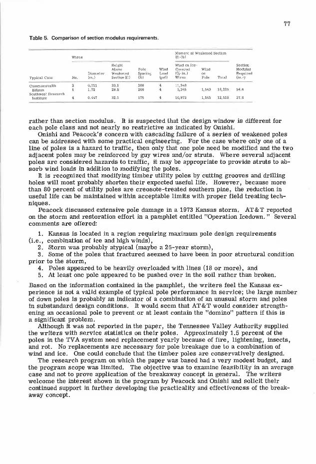
Table 5. Comparison of section modulus requirements.
Moment at Weakened Section Wires (ft-lb)
Height Wind on Ice- Section Above Pole Wind Covered Wind Modulus
Diameter Weakened Spacing Load ('/,-in.) on Required Typical Case No. (in. ) Section (rt) (ft) (psi) Wires Pole Total (in.3 )
Commonwealth 0.711 33.1 200 11,340 Ed ls on 1. 72 29.5 200 5,345 1,540 18,225 54. 6
Southwest Research Institute 0.447 32.5 175 10,973 1,545 12, 518 37.6
rather than section modulus. It is suspected that the design window is different for each pole class and not nearly so restrictive as indicated by Onishi.
77
Onishi and Peacock's concern with cascading failure of a series of weakened poles can be addressed with some practical engineering. For the case where only one of a line of poles is a hazard to traffic, then only that one pole need be modified and the two adjacent poles may be reinforced by guy wires and/or struts. Where several adjacent poles are considered hazards to traffic, it may be appropriate to provide struts to absorb wind loads in addition to modifying the poles.
It is recognized that modifying timber utility poles by cutting grooves and drilling holes will most probably shorten their expected useful life. However, because more than 80 percent of utility poles are creosote-treated southern pine, the reduction in useful life can be maintained within acceptable limits with proper field treating techniques.
Peacock discussed extensive pole damage in a 1973 Kansas storm. AT&T reported on the storm and restoration effort in a pamphlet entitled "Operation Icedown. " Several comments are offered:
1. Kansas is located in a region requiring maximum pole design requirements (i.e., combination of ice and high winds),
2. storm was probably atypical (maybe a 25-year storm), 3. Some of the poles that fractured seemed to have been in poor structural condition
prior to the storm, 4. Poles appeared to be heavily overloaded with lines (18 or more), and 5. At least one pole appeared to be pushed over in the soil rather than broken.
Based on the information contained in the pamphlet, the writers feel the Kansas experience is not a valid example of typical pole performance in service; the large number of down poles is probably an indicator of a combination of an unusual storm and poles in substandard design conditions. It would seem that AT&T would consider strengthening an occasional pole to prevent or at least contain the "domino" pattern if this is a significant problem.
Although it was not reported in the paper, the Tennessee Valley Authority supplied the writers with service statistics on their poles. Approximately 1.5 percent of the poles in the TVA system need replacement yearly because of fire, lightening, insects, and rot. No replacements are necessary for pole breakage due to a combination of wind and ice. One could conclude that the timber poles are conservatively designed.
The research program on which the paper was based had a very modest budget, and the program scope was limited. The objective was to examine feasibility in an average case and not to prove application of the breakaway concept in general. The writers welcome the interest shown in the program by Peacock and Onishi and solicit their continued support in further developing the practicality and effectiveness of the breakaway concept.