a beamformer for 120-degree secterization in lte systems€¦ · abstract— a long term evolution...
TRANSCRIPT

Abstract— A Long Term Evolution (LTE) technology is the most possible candidate for next generation mobile wireless communications. One impairment of LTE is an interference from neighboring cells, so called Inter-Cell Interference (ICI). A Fractional Frequency Reuse (FFR) has been proposed to handle the problem. Also lately, soft FFR technique has been introduced for better utilization of frequency spectrum. In addition, beamforming technique is considered to be the solution to improve the performance of wireless communication systems. Therefore, this paper proposes a new beamforming matrix suitable for LTE systems in which the coverage area is divided into three 120°-sectors. The appropriate number of antenna elements and beam patterns is discussed. The computer simulation in terms of beam patterns confirms the proposed concept. Also, a prototype of new beamformer is fabricated and tested to reveal the real performance in terms of signal-to-interference ratio and channel capacity. The obtained results show that soft FFR technique including beamforming is the best choice for LTE systems. Keywords— Beamforming network, Inter-Cell Interference, LTE, Mobile networks, Switched-beam antennas, Secterization, Secterization
1 Introduction Recently, mobile wireless communication users have rapidly demanded the use of multimedia services with the requirement of higher data access capability to the subscribers with guaranteed quality of services. In addition, the number of users has grown with unprecedented speed. A Long Term Evolution (LTE) system is the most possible candidate for next generation mobile wireless communications. From the 1st to 3rd Generation of mobile wireless communications, the development has been paid to support a fast data transfer-rate devoted to transmission of voice, image and video. However, some impairments have been left from previous generations in which the next generation of mobile wireless communications is envisaged to tackle the problems e.g. higher speed data transfer-rate, global standard to support usage in different areas, stable connection for multi-media and video or wireless teleconference. The LTE systems are a preliminary mobile wireless communication standard, formally submitted to ITU-T in late 2009 as a candidate for the 4th Generation of mobile wireless communications. It is standardized by the 3rd Generation Partnership Project (3GPP) as a major enhancement of the 4G 3GPP LTE standard. The goal of LTE is to provide a high data-rate transmission, low-latency, packet-optimized radio-access technology supporting flexible bandwidth deployments,
and an improved quality of service to reduce the delay [2]. However, the LTE technology cannot provide full benefits for mobile communications due to the problem of interference signal from neighboring cells, so called Inter-Cell Interference (ICI).
The ICI problem is more pronounced when users are moving away from cell center towards cell edge. According to this, the Signal-to-Interference Ratio (SIR) at user or mobile terminal is reduced due to two major reasons as follows. Firstly, the signal transmitted from base station to mobile terminals is dropped because of an increase in path loss. Secondly, ICI from neighboring cells becomes more pronounced when users are moving to cell edge. The techniques proposed to mitigate the ICI can be classified in several types as they can be surveyed in [3]. So far, Fractional Frequency Reuse (FFR) technique divides a whole frequency band into several sub-bands wisely allocated to some specific areas in order to improve signal quality at cell edge. Recently, a soft FFR has been proposed by managing different levels of transmitted power respective to distance between users and cell center. However, the mentioned technique cannot completely mitigate ICI.
Therefore, a smart antenna technology cooperating with soft FFR technique is envisaged to be the best solution to enhance the system quality. The smart antennas are firmed technology which is constituted by
P. WONGCHAMPA, P. UTHANSAKUL AND M. UTHANSAKUL School of Telecommunication Engineering Suranaree University of Technology
Muang, Nakhon Ratchasima 30000, THAILAND [email protected] , [email protected] and [email protected]
A Beamformer for 120-degree Secterization in LTE systems
WSEAS TRANSACTIONS on COMMUNICATIONS P. Wongchampa, P. Uthansakul, M. Uthansakul
E-ISSN: 2224-2864 287 Volume 14, 2015

antenna array and signal processing unit [4]. The key success of smart antennas is to form its main beam to a desired direction while its nulls or side lobes can be pointed to the directions of interference signals, so called beamforming. The smart antennas can be generally classified into two types: adaptive and switched beam antennas. Comparing between these types, the switched beam antennas have more advantages in terms of low complexity and implementation cost. The switched beam systems require only a beamforming network, RF switch and logic controller to select a suitable beam [5]. According to lots of advantages, the adoption of smart antenna technology in future wireless systems has a significant impact on the efficient use of spectrum, the minimization of the establishment cost, the optimization of service quality, and realization of transparent operation across multi-technology wireless networks. The work presented in [6] has revealed that beamforming is one technique to improve the cell edge performance. Also, an advantage of beamforming in 4G mobile networks in terms of avoiding collided mobile terminals in one beam has been shown in [7].
According to above motivation, this paper investigates into the LTE system performance when employing FFR schemes including conventional FFR and soft FFR. Also, several scenarios are assumed including 120-degree secterization and beamforming. In this paper, two parameters indicating the system performance, also signal quality, are Signal-to-Interference Ratio (SIR) and channel capacity. This paper begins with a brief concept of mobile communication evolution in Section 2 followed by some backgrounds of LTE in Section 3. Some introductions of frequency reuse technique and smart antennas are discussed in Sections 4 and 5, respectively. Then, performance of frequency reuse technique including beamforming for LTE systems is revealed in Sections 6 and 7. In addition, an appropriate number of antenna elements and beam patterns for LTE systems is also discussed in this section. Section 8 shows a design for beamforming matrix suitable for LTE systems. Moreover, Section 9 demonstrates a beamformer prototype proposed in this paper. Also, a result comparison in terms of beam patterns, SIR and capacity between the ones obtained from simulation and experiment is shown in Section 9. Finally, Section 10 concludes the paper.
2. Evolution of Mobile Wireless Communications Systems
Mobile cellular systems are the most popular one for wireless communication systems nowadays as they have a profound impact on people’s daily lives. As a mobile wireless communications are a factor of five for human
life so they have grown with unprecedented speed. In 1979, the first cellular systems was introduced by Nippon Telephone and Telegraph (NTT) in Tokyo, Japan. So far, mobile Cellular systems evolution has been categorized into generations as shown in Fig. 1. - The 1st Generation of mobile wireless communications (1G) transmits analog signal for speech services. The 1G systems offer handover and roaming capabilities but the 1G cellular networks are unable to interoperate between countries. The mentioned impairment is one of the inevitable disadvantages of 1G mobile networks. - The 2nd Generation of mobile wireless communications (2G) were introduced in the end of 1980s. Compared to 1G systems, 2G systems use digital multiple access technologies, such as Time Division Multiple Access (TDMA) and Code Division Multiple Access (CDMA). These 2G systems provide circuit switched data communication services at a low speed transmission [8]. Compared with 1G systems, higher spectrum efficiency, better data services and more advanced roaming can be offered from 2G systems. In Europe, the Global System for Mobile Communications (GSM) was deployed to provide a single unified standard. This has enabled seamless services throughout Europe by means of international roaming. The GSM uses TDMA technology to support multiple users during development over more than 20 years. The GSM technology has been continuously improved to offer better services in the market. New technologies have been developed based on the original GSM system, leading to some more advanced systems known as 2.5 Generation (2.5G) systems. So far, third generation (3G) systems have been introduced in the market, but their penetration is quite limited because of several techno-economic reasons. - For 3rd Generation of mobile wireless communications (3G), International Telecommunication Union (ITU) defined the demands for 3G mobile networks with the IMT-2000 standard. An organization called 3rd Generation Partnership Project (3GPP) has continued that work by defining mobile systems which fulfill the IMT-2000 standard. The 3G networks enable network operators to offer a wider range of more advanced
Fig.1 Evolution of mobile wireless communications.
WSEAS TRANSACTIONS on COMMUNICATIONS P. Wongchampa, P. Uthansakul, M. Uthansakul
E-ISSN: 2224-2864 288 Volume 14, 2015

services while achieving greater network capacity through improved spectral efficiency. Services include wide area wireless voice telephony, video calls, and broadband wireless data, all in a mobile environment. Additional features also include HSPA (High Speed Packet Access) data transmission capabilities which allow delivery of transmission speed up to 14.4 Mbps on downlink and 5.8 Mbps on uplink - New technologies in mobile communication systems and also the ever increasing growth of user demand have triggered researchers and industries to come up with a comprehensive manifestation of the upcoming 4G (4th Generation) mobile communication systems. In contrast to 3G, the new 4G framework tries to accomplish new levels of user experience and multi-service capacity by also integrating all the mobile technologies that exist (e.g. GSM – Global System for Mobile Communications, GPRS - General Packet Radio Service, IMT-2000 - International Mobile Communications, Wi-Fi - Wireless Fidelity and Bluetooth). Industry experts say that users will not be able to take advantages of multimedia content across wireless networks with 3G. In contrast, the 4G systems will feature extremely high quality video of quality comparable to HD (High Definition) TV. Its wireless download speed reaches to 100 Mbps, i.e. 50 times of 3G [9].
3. Long Term Evolution A LTE is a standard for wireless data communication
technology and an evolution of the GSM/UMTS standards. The goal of LTE is to increase the capacity and speed of wireless data networks using new DSP (Digital Signal Processing) techniques and modulations which were developed around the turn of the millennium. A further goal is the redesign and simplification of the network architecture to an IP-based system with significantly reduced transfer latency compared to the 3G architecture. The LTE wireless interface is incompatible with 2G and 3G networks, so that it must be operated on a separate wireless spectrum. However, LTE technology cannot provide full benefits due to the problem of interference signal coming from neighboring cells, so called Inter-Cell Interference (ICI). Fig. 2 shows scenario of ICI. The ICI occurs when users are moving away from cell center towards cell edge. According to this, the SIR at a mobile terminal is reduced due to two reasons as follows. Firstly, the signal transmitted from base station to mobile terminals is dropped because of an increase in path loss. Secondly, ICI from neighboring cells becomes more pronounced when users are close to their cell edge.
The SIR of the mentioned system can be expressed as follow.
1
c cn
Ei Eii
P rSIR
P r
α
α
−
−
=
=
∑ (1)
where α is path-loss exponent, cP is transmitted power from base station to cell center area of interest, EiP is transmitted power in region of cell edge belonging to the ith base station (neighboring cell), cr is distance from a user to own base station at cell center, Eir is distance from a user staying in cell edge region of neighboring cell to the base station of interest. Please note that all base stations in the system transmit the same level of power.
Furthermore, channel capacity is one factor which can describe the performance of wireless communication systems. The channel capacity used in this paper can be expressed by
2log (1 )
CSIR
B= + (2)
where B is channel bandwidth.
4. Fractional Frequency Reuse Techniques
So far, the LTE has employed several techniques to mitigate ICI. A Fractional Frequency Reuse (FFR) is one technique to relieve ICI problem mentioned in Section III. This technique offers separation of frequency spectrum resource into sectors. The reused frequency spectrum resource is shown in Fig.3. This method also provides
Fig. 2 Inter-Cell Interference scenario.
WSEAS TRANSACTIONS on COMMUNICATIONS P. Wongchampa, P. Uthansakul, M. Uthansakul
E-ISSN: 2224-2864 289 Volume 14, 2015

maximum utilization of frequency spectrum. Lately, soft FFR technique has been proposed for better utilization of frequency spectrum as shown in Fig. 4. For this technique, the transmitted power at some sub-frequencies is higher to cover the area of cell edge. This technique provides power allocation arrangement to improve cell-edge SIR while degrading SIR for users towards the other cells.
5. Smart Antenna Technology Smart antennas are an antenna technology with
capacity of beamforming to a specific direction while pointing nulls or side lobes to directions of interference signal, resulting in an increase in transmission rate and quality. The smart antennas are constituted by an antenna array cooperating with signal processing unit. For some beamforming schemes, the direction of interest is calculated so that the beam can be adjusted to the desired target destination. According to this, the smart antennas can improve link quality by combating the effect of multipath propagation or constructively exploiting the different paths, and also increasing the system capacity by mitigating interference and allowing transmission of different data streams from different antennas. Moreover, the delay arrival of signal caused by environment can be decreased. In general, there are two typical configurations of smart antennas [10].
A. Switched beam antennas
Switched-beam antennas are the simplest type of smart antenna technique [10, 11]. The switched beam antennas are constituted by an antenna array working with signal beamforming network, so called beamformer. The inter-element spacing in the array is generally distanced definitely. They provide multiple-fixed beams with high sensitivity in particular directions. The beam formation scenario of switched beam antennas is illustrated in Fig. 5 (a). Generally, the switched-beam procedures are based on a basic switching function. Firstly, the systems search for the signal strength from all formed beams. When a beam having the highest signal strength has been identified, the systems switch beam to such direction. These procedures are repeated when the user starts moving from one place to another. These systems are not complicated so that they have gained lots of attention from researcher and also companies lately. However, the speed of tracking users totally depends on beam-switching rate. In addition, SIR is relatively low when interference sources are in the region of main beam.
B. Adaptive antennas
Adaptive antennas are constituted by components similar to switched beam antennas, which are antenna array and beamforming networks. However, signal processing scheme utilized on adaptive antennas is totally different. There are some comparison between system output and desired signal (or reference signal) after performing beam-formation process. The error from the mentioned comparison is fed back to adjust the weighting coefficients repeatedly. This procedure is called adaptive process which will be stopped when there is no error in the mentioned comparison. This adaptive process helps the beamformer can point its main beam to a desired direction while pointing nulls to undesired directions as shown in Fig. 5 (b). According to this, the systems are able to provide higher SIR comparing with switched beam antennas. In addition, there is no need for antenna calibration and also the systems work well even when the number of signal is greater than that of antenna elements. However, these systems require hi-speed processing unit to calculate the weighting coefficients utilized for an independent-beam adjustment. Moreover, they need a good reference signal for maximum performance.
From the above brief discussion, switched beam antennas excluding adaptive processing are suitable for implementing at base station as they are low of cost and complexity. Therefore, this paper investigates into the performance of switched beam antennas on cellular networks. Also, several types of frequency reuse techniques are included in the investigation which will be revealed in next section.
Fig. 3 Fractional Frequency Reuse.
Fig. 4 Soft Fractional Frequency Reuse.
WSEAS TRANSACTIONS on COMMUNICATIONS P. Wongchampa, P. Uthansakul, M. Uthansakul
E-ISSN: 2224-2864 290 Volume 14, 2015

6. Simulation The performance of LTE systems in this paper is
evaluated by own developed Matlab programming. The total number of adjacent base stations is assumed by 19 cells. Every base station is assumed to transmit an equal power to the same number of mobile users. The scenarios of simulations are based on several schemes of FFR shown in Fig. 6, which are (a) sector (b) FFR (c) sector with FFR (d) soft FFR and (e) sector with soft FFR. Both FFR and soft FFR have been introduced in order to relieve the effect of ICI, especially at the region of cell edge. Also, beamforming technique is expected to be another solution to boost up the system performance. Therefore, this paper also takes into account employing of beamforming. The simulation parameters are shown in tables I and II for the cases of excluding and including beamforming, respectively. The systems performance in this paper is reflected through two indicators: Signal-to-Interference Ratio (SIR) and capacity. The SIR for the case when beamforming is excluded can be calculated using (1) but the expression shown in (3) is used to calculate SIR in case of including beamforming.
1
( )
( )
c c cn
Ei Ei Eii
G P rSIR
G P r
α
α
θ
θ
−
−
=
=
∑ (3)
where ( )cG θ is gain of antenna at base station
transmitting to region of cell center and ( )EiG θ is gain of antenna at base station transmitting to region of cell edge.
Fig. 7 shows Probability Density Function (PDF) of SIR for the systems with various scenarios. There is a comparison of cases: sector no FFR, only FFR, soft FFR, this simulation yet. As we can see, cellular systems with the use of FFR and secterization statistically provides higher SIR comparing with the ones without FFR and sector. Similarly for the ones including beamforming technique, soft FFR with secterization statistically gives the highest SIR as seen in Fig. 8. This is because of the benefits from allocating different transmitted power between cell center and cell edge (soft FFR). This brings to the reduction of ICI. Also, allocating different
(a)
(b)
Fig. 5 Beam formation for (a) switched beam antennas and (b) adaptive antennas.
(a) (b)
(c) (d)
(e) Fig. 6 Configuration of FFR schemes. (a) Sector (b) FFR (c) FFR sector (d) Soft FFR (e) Soft FFR sector.
WSEAS TRANSACTIONS on COMMUNICATIONS P. Wongchampa, P. Uthansakul, M. Uthansakul
E-ISSN: 2224-2864 291 Volume 14, 2015

frequencies to sectors can reduce effect of ICT. For clearer understanding, these two cases (with and without beamforming) are also combined as shown in Fig. 9. As we can see, the group of SIR employing beamforming technique statistically provides higher SIR even the case of without FFR. This is because the beamforming technique helps an increase in antenna gain at the desired direction while providing low gain in directions of interference signal resulting in ICI reduction.
For the evaluation of channel capacity for LTE systems, the formulas of channel capacity according to Shannon capacity are introduced in (4) to (8).FFR sector and soft FFR sector. Please note that beamforming technique was not taken into account for
( )log 12
C
BSIR= + (4)
( ) ( )1 1
4 4log 1 log 12 2
Ccenter edgeB
SIR SIR+= + + (5)
( ) ( )1 3
4 4log 1 log 12 2
Ccenter edgeB
SIR SIR+= + + (6)
Fig. 7 PDF versus SIR of the systems without beamforming.
Fig. 8 PDF versus SIR of the systems with beamforming.
Fig. 9 Comparison of SIR for cellular systems: with (red line) and without (blue line) beamforming techniques.
Table 1 Simulation parameters for case of FFR without beamforming schemes.
Number of base station 19 Inter-base station distance 1000m
Pathloss model 3GPP Macro cell [4] Number of antenna
elements 5
Inter-element spacing d=λ/2 Number of users random 100
Degree of sector 120º Table 2 Simulation parameters for case of FFR with beamforming schemes.
Number of base station 19 Inter-base station distance 1000m
Pathloss model 3GPP Macro cell [4] Number of antenna
elements 5
Inter-element spacing d=λ/2 Number of users random 100
Degree of sector 120º Antenna Array Linear array antenna
Element of antenna 5 element frequency 2.595 GHz
WSEAS TRANSACTIONS on COMMUNICATIONS P. Wongchampa, P. Uthansakul, M. Uthansakul
E-ISSN: 2224-2864 292 Volume 14, 2015

( ) ( )2 1
3 3log 1 log 12 2
Ccenter edgeB
SIR SIR+= + + (7)
( ) ( )4
3log 1 log 12 2
Ccenter edgeB
SIR SIR+= + + (8)
where B is a channel bandwidth, centerSIR is SIR in the
region of cell center and edgeSIR is SIR in the region of cell
edge. These equations are in order with respect to the configuration illustrated in Figs. 6 (a) to (e). Please note that the capacity in this paper is calculated per cell. Table III shows the calculated channel capacity for those 5
cases. It reveals that utilizing soft FFR technique including beamforming provides the highest channel capacity for both cases: with and without beamforming. This is because soft FFR provides the best SIR from the previous results presented in Figs. 7 and 8.
From the above simulation results, it can be said that soft FFR including beamforming technique is one of the best choice to improve the performance of LTE systems. Next section shows the discussion of beamforming concept suitable for LTE systems.
7. Beam-Formation Concept for LTE
As mentioned in Section V, switched beam antennas are the most suitable choice for implementing at base station. The basic configuration of these systems are presented in Fig. 10 consisting of antenna array, beamforming networks and beam selector. The beam selection can be simply performed using basic switching networks which do not require a fast or high computational function in which they are out of scope for this paper. Also, a well-known Butler matrix beamformer is the most popular technique for beamforming network so far [12-14]. According to the original concept, Butler matrix requires 4 inputs received from 4×1 antenna array, then provides 4 outputs for 4 different beam patterns. However, this kind of beamformer has been introduced for general propose in which the maximum performance of cellular systems has not been addressed. Therefore, this paper investigate into the optimum number of antenna elements which effects on the optimum number of beam patterns and beam width for LTE cellular systems.
In this investigation, the coverage area is assumed to be equally divided into three sectors (120°/sector). From running a number of simulations, we have found that using three beams gives maximum SIR covering 120° sector as depicted in Fig. 11. According to this, the beam width of each beam is 40°. Next, the appropriate number of antenna elements giving beam width of 40° is discussed. Some computer simulations have been developed to validate the concept as follows. Fig. 12 shows the beam pattern of linear array employing 4, 5 and 6 antenna elements. The obtained results show that we can have beam width of 63.41°, 41° and 29.4°, respectively. According to this, 5 antenna elements providing 41° beam width is the most suitable choice when a 120° sector having 40 beam width is require. Also, Fig.13 shows some simulation investigating the optimum number of beams per sector. For this simulation, the number of antenna elements 4, 5 and 6 are assumed. As we can see, utilizing 3-beams provides maximum SIR for all three cases.
Table 3 Simulated channel capacity.
Type Without
beamforming With
beamforming Sector no
FFR 1.4655 2.0127
FFR 2.4513 2.9962
FFR sector 2.9987 3.3491
Soft FFR 2.8769 3.2697
Soft FFR sector
3.0176 3.5531
Fig. 10 Configuration of switched beam antennas.
Fig. 11 Beam formation in 120° section.
WSEAS TRANSACTIONS on COMMUNICATIONS P. Wongchampa, P. Uthansakul, M. Uthansakul
E-ISSN: 2224-2864 293 Volume 14, 2015
From the above simulation results, Butler matrix is not the best choice for LTE cellular systems anymore. This means that we need a modification of beamformer to form 3 beams with their beam width of 41°. Also, this beamformer has to employ 5×1 antenna elements for giving maximum SIR. The mentioned beamformer is designed and discussed in next section.
8. 5×3 Beamforming Matrix As revealed in last section, the optimum number of
antenna elements is 5 and also the number of beams should be 3 for obtaining maximum SIR. This means that we have to design a new 5×3 beamformer. The design starts with calculation of inter-element phasing relative to the desired direction of arrival (θ) in azimuth as shown in (9).
Inter-element phasing = kd cosθ (9)
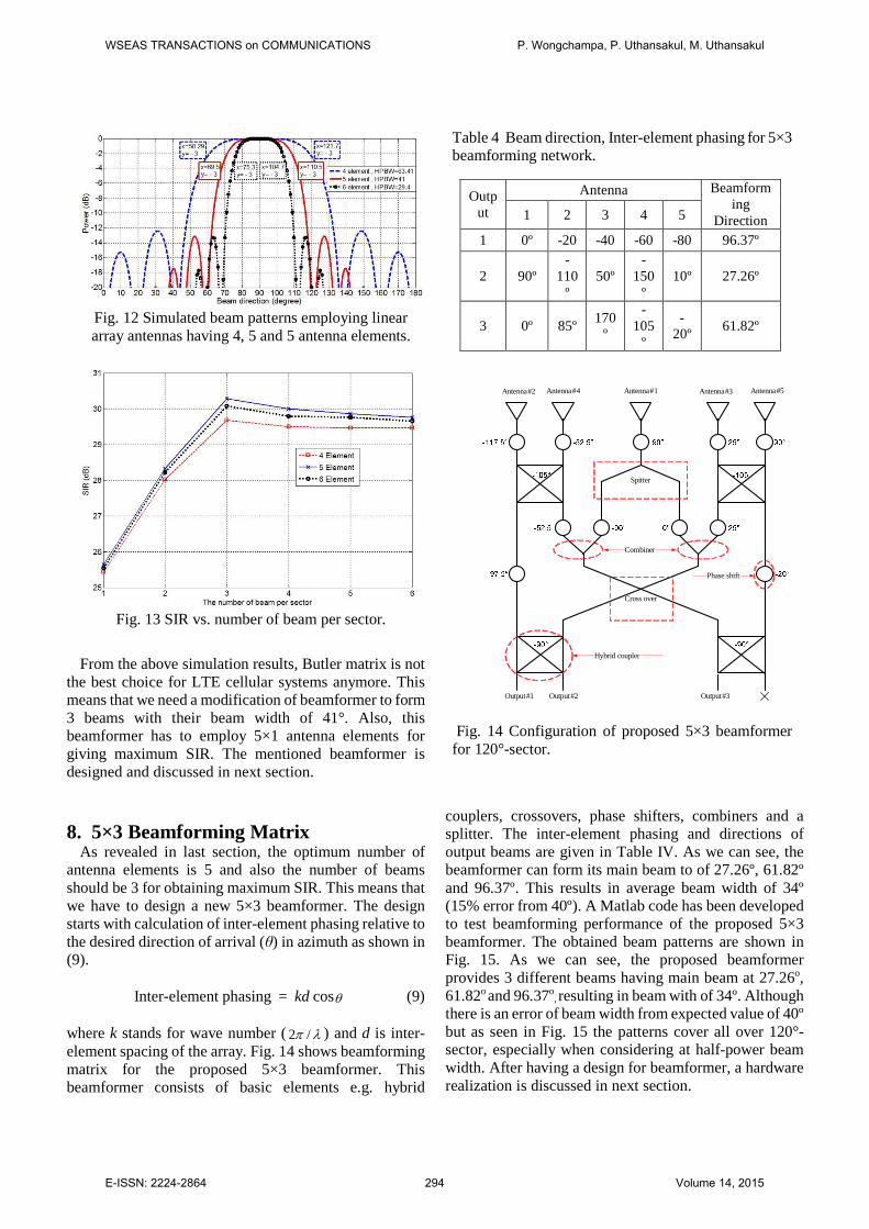
where k stands for wave number (2 /π λ ) and d is inter-element spacing of the array. Fig. 14 shows beamforming matrix for the proposed 5×3 beamformer. This beamformer consists of basic elements e.g. hybrid
couplers, crossovers, phase shifters, combiners and a splitter. The inter-element phasing and directions of output beams are given in Table IV. As we can see, the beamformer can form its main beam to of 27.26º, 61.82º and 96.37º. This results in average beam width of 34º (15% error from 40º). A Matlab code has been developed to test beamforming performance of the proposed 5×3 beamformer. The obtained beam patterns are shown in Fig. 15. As we can see, the proposed beamformer provides 3 different beams having main beam at 27.26o, 61.82o and 96.37o, resulting in beam with of 34º. Although there is an error of beam width from expected value of 40º but as seen in Fig. 15 the patterns cover all over 120°-sector, especially when considering at half-power beam width. After having a design for beamformer, a hardware realization is discussed in next section.
Fig. 12 Simulated beam patterns employing linear array antennas having 4, 5 and 5 antenna elements.
Fig. 13 SIR vs. number of beam per sector.
Table 4 Beam direction, Inter-element phasing for 5×3 beamforming network.
Output
Antenna Beamforming
Direction 1 2 3 4 5
1 0º -20 -40 -60 -80 96.37º
2 90º -
110º
50º -
150º
10º 27.26º
3 0º 85º 170
º
-105
º
-20º
61.82º
Antenna#2 Antenna#4 Antenna#1 Antenna#3 Antenna#5
Spitter
Cross over
Combiner
Hybrid coupler
Phase shift
Output#1 Output#2 Output#3
Fig. 14 Configuration of proposed 5×3 beamformer for 120°-sector.
WSEAS TRANSACTIONS on COMMUNICATIONS P. Wongchampa, P. Uthansakul, M. Uthansakul
E-ISSN: 2224-2864 294 Volume 14, 2015

9. Prototype Realization After having a design of 5×3 beamformer compatible
with LTE systems presented in last section, a prototype of proposed beamformer is constructed and tested in this section. The prototype was designed for operating at 2.5-2.69 GHz. Own developed programming using CST Microwave Studio was created to design the prototype. This prototype is constituted by antenna array, hybrid coupler, crossover, combiner/splitter and phase shifter. Those components are detailed as follows.
A. Antenna Array Linear array antennas are chosen as their simplicity. Also, the number of antenna elements are 5 for having maximum performance as pointed out in Section VII. The antenna elements are equally spaced by half-wave length at center frequency, 2.595 GHz. In this paper, printed monopole antenna is chosen and its configuration is shown in Fig. 16. The reason is that it is simple and also its width is shorter than half-wave length at 2.595 GHz. The antenna is design based on FR4 substrate having dielectric constant of 4.5 and thickness of 1.66 mm. Feed line of the antenna can be calculated using the following expressions:
2 2
8
12 0.611 ln(2 1) ln( 1) 0.39
2
A
A
r
r r
e
ew
hB B B
επ ε ε
−
= − − − − + − + − (10)
1 1 0.110.23
60 2 1o r r
r r
ZA
ε εε ε
+ −= + +
+ (11)
Then, we can calculate width and length of the antenna
respective to the configuration shown in Fig. 16 as follows:
- Width:
2
2 1or r
cW
f ε=
+ (12)
r efff f ε= (13)
- Length:
22 eff
cL L
f ε= − ∆ (14)
( )
( )
0.3 0.2640.412
0.258 0.8
oeff
oeff
WL h
Whh
ε
ε
+ + ∆ = − +
(15)
Following the above calculation, we obtain the antenna
width of 20.19oW = mm, length of 31.18L = mm and also
the width of feed line of 3.14 mm. The 5 designed
Fig. 15 Simulated beam pattern in azimuth of proposed 5×3 beamformer.
Fig. 16 Printed monopole antenna configuration.
(a)
(b)
Fig. 17 Photograph of fabricated 5×1 antenna array.
WSEAS TRANSACTIONS on COMMUNICATIONS P. Wongchampa, P. Uthansakul, M. Uthansakul
E-ISSN: 2224-2864 295 Volume 14, 2015

antennas are arranged in linear manner. The inter-element spacing can be calculated as follows:
c
fλ = (16)
when 10.17λ = cm, then we can have inter-element spacing of 5.085d = cm. Fig. 17 shows photograph of fabricated antenna according to the above design. Next, the construction of 5×3 beamformer is discussed. B. Beamforming Networks
As pointed out from Section 7, we need to design a beamformer for 5 inputs and 3 outputs, so called 5×3 beamformer. The design has been discussed in Section VIII. This section provides the detail of beamforming network fabrication as follows.
- Hybrid Coupler From the design shown in Fig. 14, two hybrid couplers having different phase-shifting values (-90º and -105º) are required. These phase values are the phase different between through and coupled ports. As can be seen in Fig. 18 (a), it is the difference between ports 2 and 4. Note that the signal is not supposed to go to port 3 (isolated port). The design can be found in several microwave
engineering book [15-17]. Finally, we can have size and dimension of 90º hybrid coupler as shown in Fig. 18 (a). Also, the photograph of fabricated one is shown in Fig. 18 (b). Then, some adjustment is performed using CST microwave studio to change the phase difference between through and coupled ports from -90º to -105º. The final size and dimension of -105º hybrid coupler is shown in Fig. 19 (a) and also its photograph of fabricated one is presented in Fig. 19 (b). - crossover As we can see in Fig. 14, we need to switch or change the path of signal. Therefore, a component named crossover is required. The design method of crossover can be found in several literatures [12-13]. Some adjustment was performed using CST microwave studio. Then, the final size and dimension of crossover designed at 2.595 GHz is shown in Fig. 20 (a). Also, photograph of fabricated crossover is presented in Fig. 20 (b).
- Combiner/Splitter The basic concept of splitter and combiner is presented in Fig. 21. The famous Wilkinson design [15, 17] is chosen to design splitter and combiner. The performance of designed combiner and splitter was tested using CST
12.575 mm
3.14 mm
12.22 mm 3.14 mm
2
3 4
1
(a) (b) Fig. 18 Hybrid coupler -90º
4 mm
4 mm3 mm
3 mm 3 mm
2 mm
7 mm 20 mm 7 mm
15 mm
1 2
3 4
2 mm
20 mm 7 mm7 mm
(a)
(b)
Fig. 19 Hybrid coupler -105º
(a)
(b)
Fig. 20 Crossover
(a) (b)
Fig. 21 Block diagram of Splitter and Combiner
WSEAS TRANSACTIONS on COMMUNICATIONS P. Wongchampa, P. Uthansakul, M. Uthansakul
E-ISSN: 2224-2864 296 Volume 14, 2015
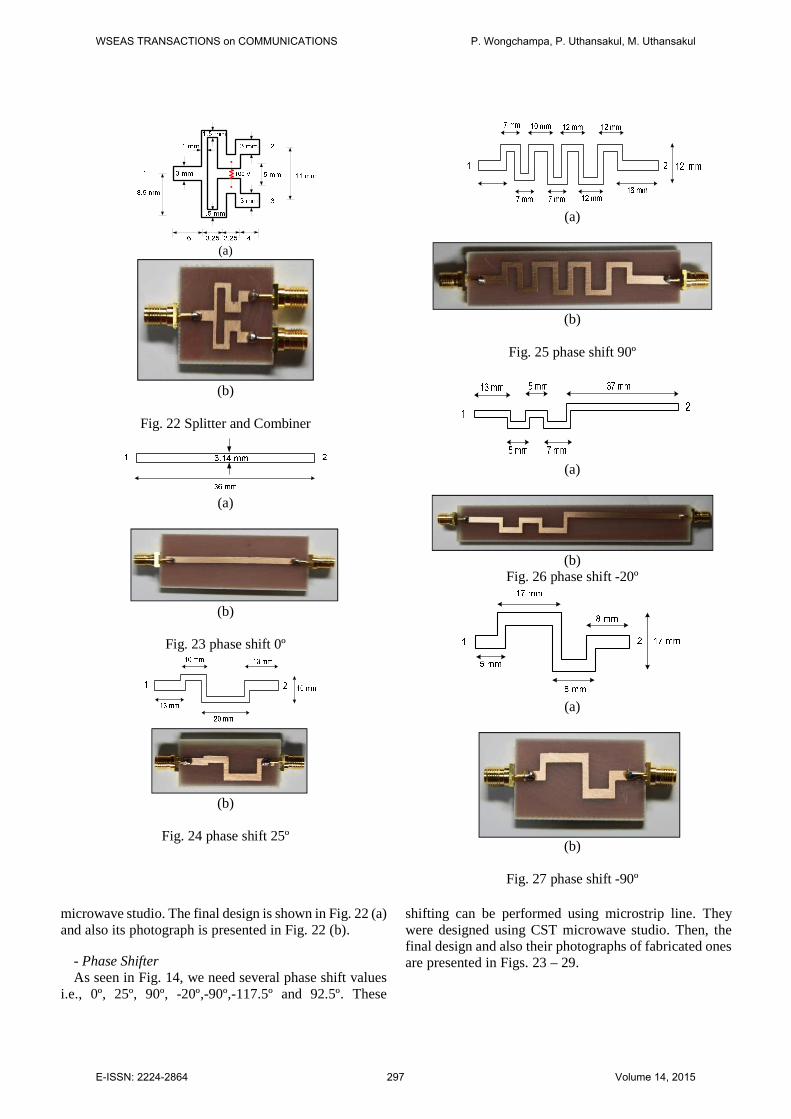
microwave studio. The final design is shown in Fig. 22 (a) and also its photograph is presented in Fig. 22 (b).
- Phase Shifter As seen in Fig. 14, we need several phase shift values i.e., 0º, 25º, 90º, -20º,-90º,-117.5º and 92.5º. These
shifting can be performed using microstrip line. They were designed using CST microwave studio. Then, the final design and also their photographs of fabricated ones are presented in Figs. 23 – 29.
(a)
(b)
Fig. 22 Splitter and Combiner
(a)
(b)
Fig. 23 phase shift 0º
(b)
Fig. 24 phase shift 25º
(a)
(b)
Fig. 25 phase shift 90º
(a)
(b)
Fig. 26 phase shift -20º
(a)
(b)
Fig. 27 phase shift -90º
WSEAS TRANSACTIONS on COMMUNICATIONS P. Wongchampa, P. Uthansakul, M. Uthansakul
E-ISSN: 2224-2864 297 Volume 14, 2015

After confirming performance of all components,
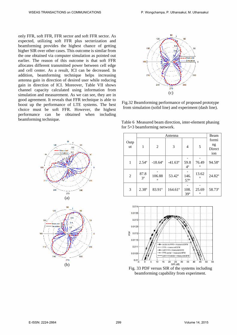
the prototype assembly is performed as its photograph is shown in Fig. 30. Also, when it is connected to the fabricated antenna array using SMA connectors, the photograph is shown in Fig. 31. The assembled prototype shown in Fig. 31 is tested in anechoic chamber using network analyzer. Table V shows the measured return loss, isolation loss and coupling loss for 5×3 beamforming network. As we can see, the 5×3 beamforming network provides return loss lower than -10 dB, lower than -15 dB for isolation loss and higher than -5 dB of coupling loss within the designated band. Next, the measurement of beamforming performance for the proposed prototype is shown. The experimental results in terms of phase shifting and also beam directions are shown in Table VI. As we can see, we obtain the beam
directions of 24.82º, 58.73º and 94.58º. Comparing with the ones expected from simulation (27.26 º, 61.82º and 96.37 º), the small deviation from expected values is within 10%. In addition, beam formation comparison between the ones obtained from simulation and experiment is shown in Fig. 32. As we can see, the prototype performs beam formation similar to simulation. In addition, these measured results are taken into account to see the real performance when operating with LTE systems working with FFR techniques. The obtained results are shown in Fig. 33, which are Probability Density Function (PDF) of SIR for 5 cases: sector no FFR,
(a)
(b)
Fig. 28 phase shift -117.5º
Fig. 29 phase shift 92.5º
Fig. 30 Photograph of 5×3 beamformer.
Fig. 31 Photograph of Assembled prototype Table 5 Return loss, isolation loss and coupling loss for 5×3 beamforming network.
Return Loss
S-Parameter
Amplitude (dB)
S-Parameter
Amplitude (dB)
S11 -18.73 S55 -16.67 S22 -17.54 S66 -19.01 S33 -17.12 S77 -18.47 S44 -16.96 S88 -17.78
Isolation loss S-
Parameter Amplitude
(dB) S-
Parameter Amplitude
(dB) S21 -22.14 S51 -24.56 S31 -23.53 S76 -23.59 S41 -25.22 S86 -22.61 S51 -23.86
Coupling loss S-
Parameter Amplitude
(dB) S-
Parameter Amplitude
(dB) S61 -3.56 S83 -3.67 S71 -3.82 S64 -3.77 S81 -3.66 S74 -3.85 S62 -3.68 S84 -3.92 S72 -3.71 S65 -3.83 S82 -3.77 S75 -3.86 S63 -3.59 S85 -3.96 S73 -3.84
WSEAS TRANSACTIONS on COMMUNICATIONS P. Wongchampa, P. Uthansakul, M. Uthansakul
E-ISSN: 2224-2864 298 Volume 14, 2015
only FFR, soft FFR, FFR sector and soft FFR sector. As expected, utilizing soft FFR plus secterization and beamforming provides the highest chance of getting higher SIR over other cases. This outcome is similar from the one obtained via computer simulation as pointed out earlier. The reason of this outcome is that soft FFR allocates different transmitted power between cell edge and cell center. As a result, ICI can be decreased. In addition, beamforming technique helps increasing antenna gain in direction of desired user while reducing gain in direction of ICI. Moreover, Table VII shows channel capacity calculated using information from simulation and measurement. As we can see, they are in good agreement. It reveals that FFR technique is able to boost up the performance of LTE systems. The best choice must be soft FFR. However, the highest performance can be obtained when including beamforming technique.
(a)
(b)
(c)
Fig.32 Beamforming performance of proposed prototype from simulation (solid line) and experiment (dash line).
Table 6 Measured beam direction, inter-element phasing for 5×3 beamforming network.
Output
Antenna Beamformi
ng Direct
ion
1 2 3 4 5
1 2.54º -18.64º -41.63º -
59.84º
-76.49
º 94.58º
2 87.83º
-106.88
º 53.42º
-146.57º
13.62º
24.82º
3 2.38º 83.91º 164.61º -
108.39º
-25.69
º 58.73º
Fig. 33 PDF versus SIR of the systems including
beamforming capability from experiment.
WSEAS TRANSACTIONS on COMMUNICATIONS P. Wongchampa, P. Uthansakul, M. Uthansakul
E-ISSN: 2224-2864 299 Volume 14, 2015

Table 7 Channel capacity.
Type Without
beamforming
With beamforming (simulation)
With beamforming
(measurement) Sector no
FFR 1.4655 2.0127 1.9878
FFR 2.4513 2.9962 2.8539
FFR sector
2.9987 3.3491 3.2989
Soft FFR 2.8769 3.2697 3.1445
Soft FFR sector
3.0176 3.5531 3.4543
10. Conclusion
This paper has investigated benefit of several types of frequency reuse techniques for LTE systems. The computer results have indicated that soft FFR is the best choice providing maximum performance in terms of SIR and channel capacity. Moreover, the investigation has included the beam formation into the systems. Then, from running a number of simulation, the optimum number of array antenna elements and beam patterns for covering all over 120º sector is 5 and 3, respectively. Therefore, a prototype of 5×3 beamformer has been originally designed and tested in anechoic chamber. The obtained results have indicated that the proposed prototype works well as expected. Also, soft FFR plus secterization and beamforming provides maximum SIR and channel capacity.
Acknowledgment This work was supported by Suranaree University of
Technology, Thailand.
References:
[1] http://en.wikipedia.org/wiki/4G [2] 3GPP TSG RAN TR 25.913 v7.3.0, Requirements for
Evolved Universal Terrestrial Radio Access (UTRA) and Universal Terrestrial Radio Access Network (UTRAN).
[3] Farooq Khan , “LTE for 4G mobile broadband air interface technologies and performance” Cambridge University Press 2009.
[4] A. Alexiou and M. Haardt, “Smart antenna technologies for future wireless systems: trends and challenges,” IEEE communications Magazine, vol. 42, 2004, pp. 90-97.
[5] J. C. Liberti, Jr., T. S. Rappaport, Smart Antennas for Wireless Communications:IS-95 and Third Generation CDMA Applications. Printice Hall PTR, NJ, 1999
[6] Guangyi Liu, Jianhua Zhang , et al ,“Downlink interference coordination and mitigation for future LTE-Advanced system” in Proceedings of the 15th Asia-Pacific Conference on Communications 2009.
[7] M. Lott , “Adaptive random access with beamforming in 4G mobile networks” in Proceedings of IEEE Vehicular Technology Conference 2006.
[8] Jawad Ibrahim, “4G Features” Bechtel Telecommunications Technical Journal, December 2002.
[9] K.R.Santhi, Prof.V.K.Srivastava, G.SenthilKumaran, “Goals of True Broad band’s Wireless Next Wave (4G-5G)” 0-7803-7954-3/03/2003 IEEE.
[10] Constantine A. Balanis; “Introduction to Smart Antennas,” Morgan & Claypool Publishers., 2007.
[11] Ho, Ming-Ju, Stüber, Gordon L. and Austin, Mark D. Performance of Switched Beam Smart Antennas for Cellular Radio Systems. IEEE Transactions on Vehicular Technology. 1996, Vol. 47, p. 545.
[12] M. Bona, L. Manholm, J. P. Starski, and B. Svensson, “Low-loss compact Butler Matrix for a microstrip antenna,” IEEE Trans. Microw. Theory Tech., vol. 50, no. 9, Sep. 2002, pp. 2069–2075.
[13] H. Moody, “The systemmatic design of the Butler matrix,” IEEE Transactions on Antennas and Propagation, vol. 12, Nov.1964, pp. 786-788.
[14] Shao-Hua Chu; Hsin-Piao Lin; Ding-Bing Lin; “Performance enhancement by using switch-beam smart antenna in 802.11a WLAN system,” IEEE/ACES Intern. Conf. on Wirel. Comm. and Applied Comp. Electromag., 3-7 April 2005, pp. 1001 – 1005.
[15] David M. Pozar (1998). Microwave Engineering 2nd edition, John Wiley & Sons, Inc. 1998.
[16] Annapurna Das and Sisir K Das, Microwave Engineering,Tata McGraw-Hill Publishing Company Limited, 2000.
[17] Collin, R. E., Foundations for Microwave Engineering, John Wiley & Sons, Inc., 2001
WSEAS TRANSACTIONS on COMMUNICATIONS P. Wongchampa, P. Uthansakul, M. Uthansakul
E-ISSN: 2224-2864 300 Volume 14, 2015