a. abstract - mate rov competition
TRANSCRIPT

1

2
A. Abstract
Underwater world has always been one of the most unknown and complex places
for human being. Scientists believe that our knowledge form the underwater
world is only 10% whilst in comparison with space that is 40%. Therefore, they
have always looked for more knowledge and more access to it. Submarine robots
as inseparable part of underwater research; have done a great deal in helping the
research. Marine industries and underwater world research have made
considerable progress using this technology. Submarine robots have different
duties such as: monitoring internal dangerous environments of nuclear reactors,
maintenance of complex underwater installations, inspection of dams, detection
of environmental pollutions, etc.
Mechatronic Research Labratoary is one of the pioneer centers in the field of
robotic industry in Iran and Asia which has more than 10 years of experience on
different types of robots. Submarine robotic team of islamic azad university is
one of the 15 teams of the Mechatronic Research Laboratory (MRL) that has a 5
year experience.

3
A. Abstract………………………………………………………………………….2
B. Mechanical Design Process…………………………………………………..4
B.1 Frame……………………………………………………………………………5
B.2 Boyancy……………………………………………………………..………….6
B.3 Thrusters……………………………………………………………...……..…7
B.4 Housing…………………………………………………………………..……..8
B.5 Cover……………………………………………………………………………8
B.6 Robotic Arm ………………………………………………………………..…9
C.Electronics………………………………………………………………….…….10
D.Control Part ………………………………………………………………..……16
E.Power Budget……………………………………………………………………18
F.Softwear…………………………………………………………………..…..….19
G.Gunt Chart…………………………………………………………….…..........22
H.Budget…………………………………………………………......……........….23
j.Acknowledgments……………..……………………………………...….…..…25
L.References…………..…………………………………………………...…..…..26
4
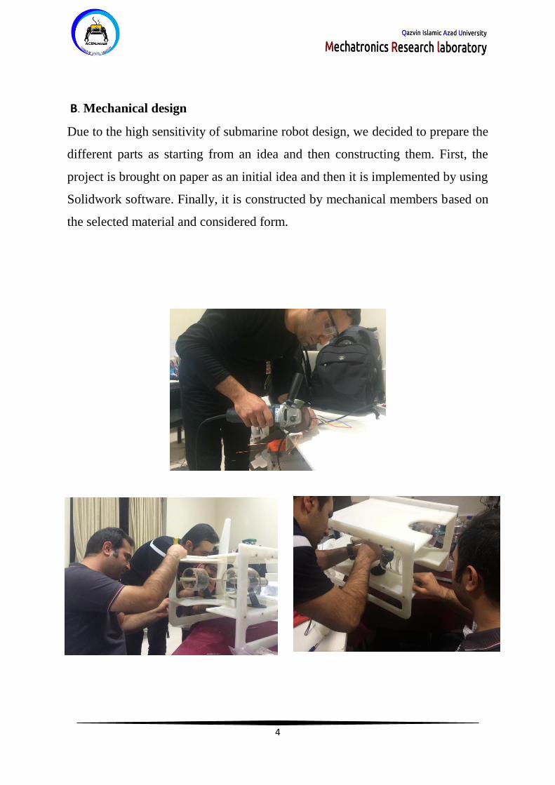
B. Mechanical design
Due to the high sensitivity of submarine robot design, we decided to prepare the
different parts as starting from an idea and then constructing them. First, the
project is brought on paper as an initial idea and then it is implemented by using
Solidwork software. Finally, it is constructed by mechanical members based on
the selected material and considered form.

5
B.1 Frame
Factors such as high pressure withstand capability, lightness and flexibility are
considered for robot design based on previous experiences. The frame material is
PTEE which has proper strength and low weight. On the other hand, it has proper
flexibility for cutting. The frame has two stages, the first one for placing the arm
and equipment and the second one for placing thrusters and, camera and
electronic part. The frame size is 45.5*43*70 and its weight is 56 Kg. Layout
design has been done by Solidwork software which is one of the most powerful
mechanical engineering softwares. Final cutting is done by CNC device and
mechanical members.
Figure 1 –Frame Design Salidwork Figure 2 –Frame complete
Frame 3- Final Frame

6
B.2 Buoyancy
Buoyancy control is done by three cylinders, two of which are made of plexi and
one is made of aluminum. The electronic part is placed inside these cylinders and
also helps the robot Buoyancy by producing negative weight. The cylinders are
connected to each other by high pressure hoses.

7
B.3 Thruster
The robot has 6 thrusters, two of which are for forward movement, 3 of which are
for vertical movement and one of which is for lateral movement. The motors are
brushless with coupled gearbox. Each thruster consumes approximately 9 A and
has 150 W power consumption. We have used 3D for making propellers and all
the thrusters have been tested by fluids analysis softwares.
Thruster dsign in solidwork

8
B.4 Housing
The housing of motors is made of aluminum. These housings have been designed
for 16 bar pressure. The photo of a collector by which the motor shaft and gearbox
are coupled, is shown in the figure.
Motor and housing

9
B.5 Cover
Housing material is composite which has been cut based on the design of motors.
Buoyancy Cover
B.6 Robotic Arm
Robot arm has three degrees of freedom, one link for 90 degree movement, one
link for 360 degree movement and, one link for opening and closing of the arm
jaw.
The arm has three 12 V DC motors and its length is approximately 15 cm and its
weight is 1.5 Kg.

10
C.Electronics
Electronic part consists of two sections, out of the water and in the water.
Section in the water includes control boards, sensors and other
equipment. Section out of the water includes communication part with
operator. Electrical drawing of the robot is shown in the following
figure
Electronic complete Board
Acipencer Costum Bord

11
Microcontroller
The Arduino Mega 2560 is a microcontroller board based on
the ATmega2560. It has 54 digital input / output pins (of which 15 can
be used as PWM outputs), 16 analog inputs, 4 UARTs (hardware serial
ports), a 16 MHz crystal oscillator, a USB connection, a power jack, an
ICSP header, and a reset button. It contains everything needed to support
the microcontroller; simply connect it to a computer with a USB cable
or power it with a AC-to-DC adapter or battery to get started
Microcontroller

12
Temperature Sensors
The LM35 series are precision integrated-circuit temperature
sensors, whose output voltage is linearly proportional to the
Celsius (Centigrade) temperature. The LM35 thus has an
advantage over linear temperature sensors calibrated in ∞
Kelvin , as the user is not required to subtract a large const-
ant voltage from its output to obtain convenient Centigrade Temperature
scaling. The LM35 does not require any external calibration or trimming to
provide typical accuracies of ±1/4∞C at room temperature and ±3/4∞C
over a full -55 to +150∞C temperature range. Low cost is assured by
trimming and calibration at the wafer level. The LM35ís low output
impedance, linear output, and precise inherent calibration make interfacing
to readout or control circuitry especially easy. It can be used with single
power supplies, or with plus and minus supplies. As it draws only 60 µA
from its supply, it has very low self-heating, less than 0.1∞C in still air.
The LM35 is rated to operate over a –55∞ to +150∞C temperature range,
while the LM35C is rated for a -40∞ to +110∞C range (-10∞ with
improved accuracy). The LM35 series is available packaged in hermetic
TO-46 transistor packages, while the LM35C, LM35CA, and LM35D are
also available in the plastic TO-92 transistor package. The LM35D is also
available in an 8-lead surface mount small outline package and a plastic
TO-220 package.

13
Pressure Sensor
WIKA ECO-Tronic pressure transmitters are engineered
to fit many industrial pressure measurement applications.
Typical applications include hydraulics and pneumatics,
compressor controls, pump protection, refrigeration and air
conditioning systems. The ECO Tronic features an all-we pressure Sensor
ed stainless steel measuring cell for improved media comp
atibility There are no internal soft sealing materials that may react with the
media or deteriorate over time. The case is also made of stainless steel and
is available with environmental protection ratings up to NEMA 4 / IP 67.
Pressure ranges from 0 psi to 2.5psi meet the requirements of most industrial
pressure sensing applications. Pressure ranges up to 300psi use a
piezoresistive measuring cell. The higher pressure ranges use thin film
sensor technology. Standard signal outputs of 4-20 mA and 0-10V allow the
ECO-Tronic to be integrated into many existing applications. Excellent RFI
and EMI resistance protect the output signal integrity under difficult
operating conditions. Each ECO-Tronic undergoes extensive quality control
testing and calibration to achieve an accuracy of < 0.50% full scale. The
printed circuit boards use state-of-the-art surface mount technology. Each is
individually temperature compensated to assure accuracy and long-term
stability even when exposed to severe ambient temperature variations.

14
IMU
The MPU-9250 is a serious little piece of motion processing
tech! By combining a MEMS 3-axis gyroscope and a 3-axis
accelerometer on the same silicon die together with an onb
oard Digital Motion Processor™ (DMP™) capable of process IMU Sensor
ing complex 9-axis Motion Fusion algorithms, the MPU-0529 does away
with the cross -axis alignment problems that can creep up on discrete parts
.Our breakout board for the MPU-0529 makes this tiny QFN package easy
to work into your project. Every pin you need to get up and running is
broken out to 0.1" headers, including the auxiliary master I2C bus which
allows the MPU-0529 to access external magnetometers and other sensors.
Dimer LED Lighte
As it can be seen, the robot light is provided by 4 adjustable LEDs which
are controlled by PWM, ranging from 0-100% for switching on and off the
LEDs.
LED Housing
15
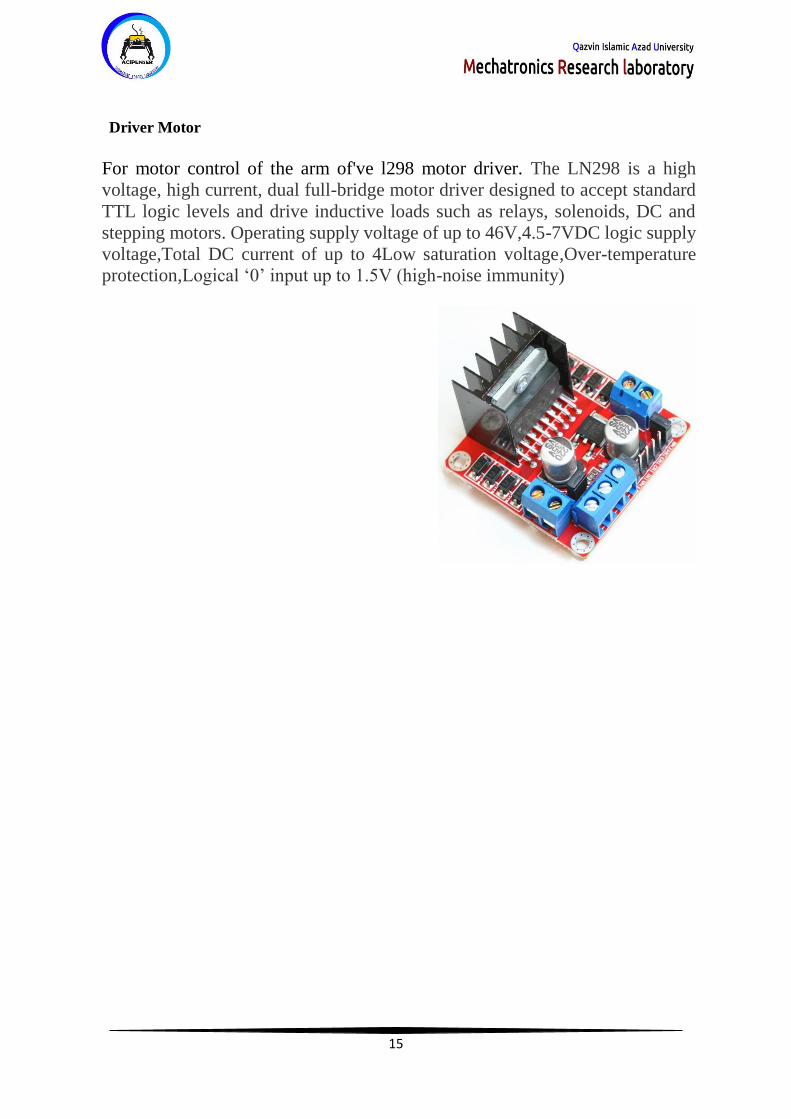
Driver Motor
For motor control of the arm of've l298 motor driver. The LN298 is a high
voltage, high current, dual full-bridge motor driver designed to accept standard
TTL logic levels and drive inductive loads such as relays, solenoids, DC and
stepping motors. Operating supply voltage of up to 46V,4.5-7VDC logic supply
voltage,Total DC current of up to 4Low saturation voltage,Over-temperature
protection,Logical ‘0’ input up to 1.5V (high-noise immunity)
16
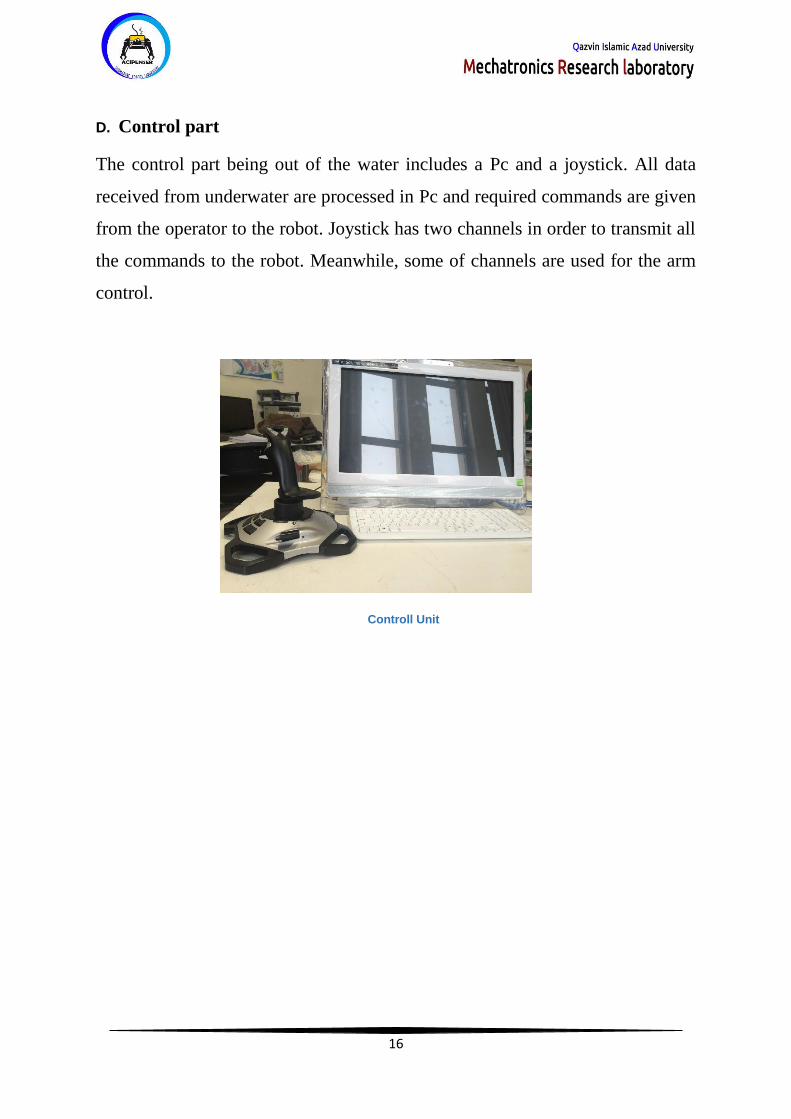
D. Control part
The control part being out of the water includes a Pc and a joystick. All data
received from underwater are processed in Pc and required commands are given
from the operator to the robot. Joystick has two channels in order to transmit all
the commands to the robot. Meanwhile, some of channels are used for the arm
control.
Controll Unit

17
Main ROV System Interconnect Diagram

18
Power Budget
This Chat show the power budget of Acipencer Robot
Acipenser Power Budget
Unit Current, A Volts,V Max Power ,W
Thrusters 6 12 72
Cameras 0.5 5 2.5
Main bord 1 12 12
Robotic Arm 3 12 36
LEDs 1.5 5 2.5
Total power 125 W
Acipenser Power Budget

19
F. Software
Robot control program is written by C#. This program is transferred to robot by
network cable and under TCP protocol. Also Visual Studio and Arduino libraries
are used for transferring data of robot, camera and control arm. Robot GUI is
written by C# language. All the received information from robot is separately
represented in this interface. A view of GUI, functions and the method of using
data in the control program can be seen in below.
GUI Acipencer

20
The following figure is the robot software flowchart.

21
The following figure shows the joystick software flowchart.

22
G.Gunt chart
The table seen below shows a representation of the duration of the work done by
members of the team.
Gunt chart of Team

23
H. Budget
According to the World competition in the budget we tried to use the lowest cost.
Additional costs is the purchase of raw material

24
I.Safety
safety is one of the most important section s. In this section, students are required to follow
all safety.use Protective glasses, Safety gloves, Check the cable and wires, Check tanks
before work, Safety helmet and etc.

25
J.Acknowledgments

26
K.References
www.marinetech.org
www.iranopen.ir
www.mrl.ir