a-a0 army electronics research and development …
TRANSCRIPT

A-A0 637 ARMY ELECTRONICS RESEARCH AND DEVELOPMENT COMMAND FO-ETC F/ 9/2mICROCOWER INTERFACING TECHNIQUES.(U)JUL 80 1 T CERVINI
UNCLASSIFED DELEW-TR-80-1 L
-7-8.Tmw-- EM.'--.mo

140 2.0~i~11111-2.
MICROCOPY RESLTO ETC;

RESEARCH AND DEVELOPMENT TECHNICAL REPOPT
DELEW -TR-80
, MICROCOMPUTER INTERFACING TECHNIQUES
John T. Cervini0 /ELECTRONIC WARFARE LABORATORY
I July 1980
D I STR IBUT ION STATEMENT
Approved for public release:distribution unlimited.
L. AUG L 8 1980
3. !,." A
E ERADCOMl US ARMY ELECTRONICS RESEARCH & DEVELOPMENT COMMAND, .FORT MONMOUTH, NEW JERSEY 07703
80 8 27 079 lA-M167

Discliers
The citation of trade names and names of manufacturers inthis report is not to be construed as official Governmentindorsement or approval of commercial products or servicesreferenced herein.
Disposition
DestrOY this report when it is no longer needed. Do notreturn it to the originator.
HiA-Pm-63 3-78

- -~ -READ INSTRUCTIONSREPORT DOCUMENTATION BEFORE COMPLETING FORM
RE PORT NUMBER 2. GOVT ACESSION NO. 3. RECIPIENT'S CATALOG NUMBER
DELEW-TR-89 1______________4ITLE- - S. TYPE OF REPORT A PERIOD COVERED
Final 2-01-79 thru 2-01-80ICROCOMPUTER INTERFACING _TECHNIQUES 6. PERFORMING ORG. REPORT NUMBER
-kI RL1 S. CONTRACT OR GRANT NUMBER(a)
JOHN T./CERVINI(Ii) j>//2 / ' -'
. F O0. PROGRAM ELEMENT. PROJECT, TASK
9RPERFORMING ORGANIZATION NAME AND ADDRESS A a WORK UNIT NUMBERSCommanding General
US Army Electronics Research & Development CommancATTN: DELEW-E // IT1627135-A 42,04-02 "
Fort Monmouth, NJ 07703 ' -"= i
I. CONTROLLING OFFICE NAME AND ADDRESS 12. REPORT DATEJuly 1 "0 _
IS. NUMBER OF PAGES
14. MONITORING AGKLCV" MAM"-DAOORES"f afirent-Choiw *Ufjia*Dll LCe) IS. SECURITY CLASS. (of thi report)
:7i, / ~ "" A , 1Unclassified '
/ IS.. DECLASSIFICATION/ DOWNGRADINGSCHEDULE
t*. DISTRIBUTION STATEMENT (f this Relport)
Distribution is unlimited; approved for public release.
17. DISTRIBUTION STATEMENT (of the abstract entered In Block 20, it different Ito Reporit)
IS. SUPPLEMENTARY NOTES
I. KEY WORDS (Continue on evevree Old@ if necesry and identify by block number)
MC6800-Microprocessor, Microcomputer, Interface, Data Acquisition, assemblylanguage.
ABSTRACT (Continue on reverse aide it necesair and Identify by block number)
A number of parallel interfacing methods for microcomputer systems are discussewhich use the Motorola 6800 microprocessor as a central processing unit. A min-
imum processing system is defined, and the individual electronic components aredefined and explained. The report also illustrates the requirements of thePeripheral Interface Adapter integrated circuit in effecting the Input/Output of
data. The techniques and instructions necessary to interface signal generators,
printers, and data acquisition systems to a microcomputer are also described.
to ,- 1473 R DITION Ol I NOV 6f IS OBSOLETE --7' 77 UNCLASSIFIED
i SEC UJ-ITY CLASSIFICATION OF THIS PAGE ( Wan at* EateeeO

"'NTS
'-RODUCTION
DISCUSSION
Microcomputing SystemsI'IA Interface Requirments-i?,4al Generator InterfacePrtnter Interface t
-' Accuisit!on Systems 2f
.ONCLUS IONS 36
IBLIOGRAPHY 37
FIGURES
. nimum Microcomputer Configuration. 22. MC 6800 Microprocessor Block Diagram. 33. MCM 6810A Random Access Memory (RAM). 44. MCM 6830A Read Only Memory (ROM).5. MC 6820 Peripheral Interface Adapter (PIA) Block Diagram.6, vCY 6810A RAM bus interface.. MCM 6830A ROM bus interface.
X fC 6820 PIA bus interface.- Motorola MEK 6800 Dl Evaluation Module.
.. Motorola MEK 6800 D2 Evaluation Module.Motorola MEK 6800 D2 Display Board.
i, . RS 232C tormat (30 characters/sec.). 1613. Peripheral Interface Adapter (PIA) functions. 1_14. WAVETEK Model 3001 Signal Generator. 1415. Signal generator block diagram. i416. Rear panel connector and pin ID.17. Signal generator outputs. 17,1k18. DPP-7 Digital Panel Printer. i919. DPP-7 block diagram. 2020. Handshaking with the printer on the "B" side. 2121. APP-20 block diagram. 2%22'. APD-20 timing - printing one line. _422. Pulse output on "B" side configuration. 252*. CB2 outputs in pulse mode. 2525. CB2 inverted pulses at various intervals. 2726 Successive Approximation A/D Converter. 28.1' Dual - slope integrating waveform. 2928. SHM-4 Sample and Hold Circuit. 30)9. N-Channel multiplexer circuit. 31
i

Za~e
30. ADC-149 S/A A/D Converter* 32
31. Handshaking with peripheral on "B" side. 34
TABLES
1. APP-20 1/0 Pin Connection. 212. APP-20 1/0 Interface Connections. 223. I4UX Channel Addressing. 35
7FI

MICROCOMPUTER INTERFACING TECHNIQUES
INTRODUCTION
The state-of-the art in electronics has advanced to the point wherea number of "smart" processors exist which can be applied to an infinitenumber of applications. The microprocessor unit (MPU) is rapidly replacingboth digital and analog circuitry in the industrial control environment.At the same time, the MPU is beginning to challenge the once exclusive
domain of the minicomputer manufacturers, who themselves, are challengingthe main-frame producers.
Military designers and planners should become aware of the power andflexibility of the microprocessor and its ability to lower the cost ofdesigning electronic equipment. These assets can be realized with theadditional benefit of increased capability. The current processing powerof the MPU, in general, is quite wide. However, each individual micro-processor operates within its own limited realm, based on the size of itsaddress bus and data word. This report will concentrate on the Motorola6800 MPU16 which has an 8-bit data word and a 16-bit address bus that canaccess 2 or 65,535 locations.
Microprocessors by themselves are not usually self-contained units,-although "single-chip" MPU's now exist. Strictly speaking, the micro-processor is an incomplete processing module, consisting of an arithmeticand logic unit (ALU), an internal instruction set, internal registers, andinput/output (I/0) buffers. In order to be useful, the MPU needs a num-ber of peripheral circuits to allow it to communicate with the outsideworld. A minimum configuration consists of an MPU, read/write memory,an interface circuit, and an external clock system (Fig. 1). This totalpackage would be defined as a microcomputer.
This report deals specifically with microcomputer configurationsbased on the Motorola 6800 MPU and its family of circuits. Many of thetechniques explored here are general enough to be applied to other MPUfamilies, such as the Rockwell 6502 microprocessor. A tutorial will not begiven on the understanding of MPU technology; a basic knowledge of micro-processors and assembly language programming will be assumed. Not allinterface applications will be treated in this report. It will concen-trate on parallel interface techniques, leaving serial interface develop-mets, such as modems, to other investigations.
DISCUSSION
Microcomputing Systems
The minimum systems microcomputer configuration, as shown in Fig. 1,
is physically represented by individual silicon chips assembled ontoDual Inline Packages (DIP's). The design engineer who wishes to fabricatea custom microcomputing system for a specific application must design the
ZEN

6871
CLOCK
680 0 CONTROL
ADDRESS
ROMO
Figure 1. Minimum Microcomputer Configuration.
2

proper connections for the address, data, and control buses. Next he mustput together the various hardware components, program the necessary software,and finally test and debug the entire system. To accomplish this feat, thedesign engineer must have a working knowledge of the integrated circuits(IC's) needed in the design.
AIS AII A13 A12 All A10 A9 A8 A7 A6 A5 A4 A3 A2 Al AO
25 24 23 22 20 19 is 17 16 15 14 1:3 12 11 to 9
Oufte~t Outputrl
Clock, 401 3--- ,
Clock, 62 37
No.-Maskabld, Mnt67ruat 6 --- Counter " -- Counter L
interrupt Request 4 - Decode Sand PO nter l o'te
Thre.-S t o Contol 9ol
Oste Bus na Ie 36 n
Ous Avlsilabloe 7 -- 0- Regimte, R 0 Fesste' L
Velid Menory Address 5
R..d/Writs 34 R AccumultOA
Pin. 121 07 6 05n4s0ru0ctio0
Register t 6
TcConditi on rCode
Register r
twDye(-it/yeaeiter tacoais headdesoUtenx
Va a - Pin n 26 2 2a 29 30 31 3-3eVSS- Vin 1.2 06 05 04 0:3 02 01 0
Figure 2. MC 6800 Microprocessor Block Diagram
Figure 2 is an expanded block diagram of the MC 6800 microprocessor.The processor is a b direct.onal, bus-orented, 8-brt (data word) parallelmachine with 16 bits of address. The MC 6800 has two 8-bit accumulators,A and B, which are used to hold operands and results from the ArithmeticLogic Unit (ALU). The 16-bit index register, X, stores 16 bits of memoryaddress for the index mode of memory addressing. The stack pointer is a
two byte (8-bit/byte) register that contains the address of the nextSavailable location in an external push-down /pop-up stack. The stack is
normally a random access read/write memory that may have any location:i '*(address) that Is convenient. The program counter is a 16-bit register that
contains the current program address. The condition code register is aflag register which contains 6 bits to indicate the results of an ALUoperation. Processor control lines include Reset, which automatically
restarts the processor; Interrupt Request; and Non-Maskable Interrupt to
1. M6800 Microcomputer System Design Data, Motorola Inc., 1975
3

monitor peripheral status. Finally, there is a Three-State Control, DataBus Enable, and a Halt Control Line, which can be used for Direct Memory Ac-cess (DMA) or multi-processing.
Read/write memory for the MPU can be provided by one or more RandomAccess Memory (RAM) chips. For dedicated control applications, where onlya small amount of memory is needed to store intermediate results, theMCM 6810 device is easily used. This chip is a 128x8-bit totally staticRAM, which was designed to operate in bus-organized systems (Fig. 3). Thestatic property of this device allows it to function without being periodic-ally "refreshed" by the MPU; i.e., it retains data in a location as long aspower is applied to the circuit.
Read Only Memory (ROM) for programmed instruction is provided by theMCM 6830 1024x8-bit IC (Fig. 4). This device is a "masked" chip, whichmeans that the memory locations are pre-programmed by the manufacturer witha specific set of instructions. This is done when the ROM is to be usedas a limited function operating system. More will be said about this later.The design engineer will normally use an ultraviolet (UV), electricallyprogrammable, read-only memory (EPROM). In any case, a ROM cannot bewritten into, but can only be read from. Also, the MCM 6830 is a staticbyte oriented device designed to operate with the MC 6800 MPU.
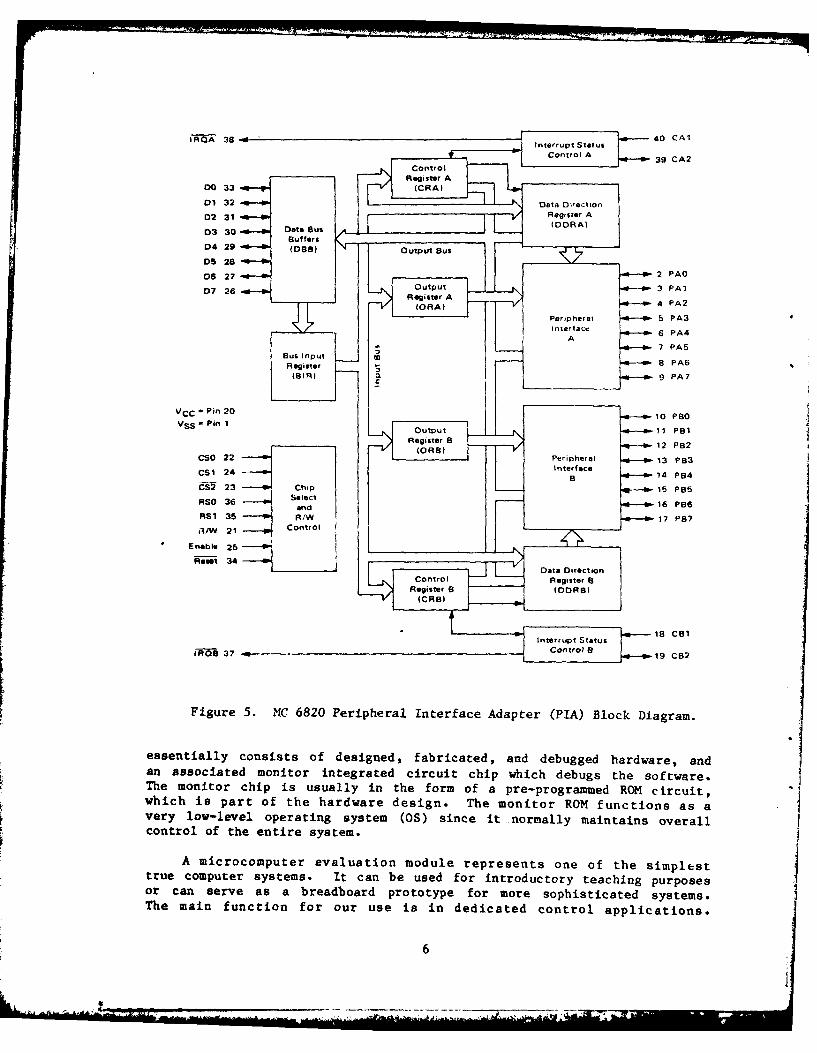
The MC 6820 Peripheral Interface Adapter (PIA) provides the universalmeans of interfacing peripheral equipment to the MC 6800 microprocessor.A block diagram is presented in Fig. 5. This device is capable of inter-facing the MPU to peripherals through two 8-bit bidirectional peripheraldata buses (PAO-PA7 and PBO-PB7) and four control lines (CA1, CA2, CBl,CB2). The functional configuration of the PIA is programmed by the MPUduring system initialization. Each of the peripheral data lines can beprogrammed to act as an input or output; each of the four control/interruptlines can be programmed for one of several control modes.
- so2 00AO 23 - 3 DiA 22 - D2
A2 21 - Memory 3-S50 °3A3 2 - Adoress Matrix Bfe 0-'1
A Decode (12Sx8) 6 04A4 19 [905
A5 18 8 D6A6 I 9 D7
rS 15
C4 14
CS3 13 MentroV
5S2 12d'l I I VCC , Pin 24
CSO 10 16 Read/Write
Figure 3. MCM 6810A Random Access Memory (RAM).
4

AO 24 2 DOA 1 23 43 01
A2 22 - 4 2A3 21 Memory 3-State 5 D3A4 20 - Address Matrix Buffer 6 D4A5 19 - Oecode (1024 x 5) D5
CSO 10
A7 17AS 16 - 9 D7
CS0" 10
CS I•
11CS2" 13CS3* 14
VCC = Pin 12
Active level defined by the customer. Gnd = Pin 1
Figure 4. MCM 6830A Read Only Memory (ROM).
The interconnection of these components to form a microcomputer systemis relatively straightforwrd with the MC 6800 device. Since all componentsoperate at the same transistor-transistor logic (TTL) levels and with the samedrive capability, the data, address, and control lines can be interconnectedwithout adding external TTL buffers. Figure 6 shows the 6810 RAM bus inter-face to the MPU and the rest of the components of the system. The RAM hassix Chip Select (CS) inputs, four active-low and two active-high, whichinterface directly to the address bus. Four of the CS's are used to decodethe system address lines. In small- and medium-sized systems, this addressdecoding will be sufficient to distinguish between all integrated circuitsin the system without using any additional address decoding packages.
The ROM bus interface (Fig. 7) is similar to that of the RAM, and alloutputs may be connected directly to the data bus without drivers. Ithas 10 address lines and four CS's, three of which are used to provide theaddress decoding that selects a particular location within the ROM.
The PIA system interface is shown in Fig. 8. It has three CS lines andtwo Register Select (RS) lines, RSO and RS1, connected to the address bus.Two Interrupt Request (IRQ) lines, IRQA and IRQB, are used to signal theMPU when an interrupt has occurred. The data bus lines, Chip Select,Read/Write, and Enable have the same static and dynamic characteristics asthe other peripherals in the MC 6800 system. The Reset line is used toinitialize the PIA. The RS lines serve the same purpose in the PIA as theaddress lines do in memory; they address the control and status registers,thereby making the PIA look like memory to the microprocessor.
Although the interfacing of components is in general straightforward,it can be somewhat time-consuming and tedious to design a system fromscratch. Fortunately, there are products on the market that can ease thisburden because they have hardware already designed and debugged. Thissimplifies writing the desired program to accomplish a particular task.Some difficulties will still arise since some type of development system willbe needed to debug the program in order to insure correctness. We can takethings a step further by using a microcomputer evaluation module, which
5
i A 38 -dIntru e 40 CAl
Control A 39 CA2
Register A00 33 (CRA)
01 32 7 Data DirectionD2 31:D AD2 31 'RegisterA
D3 30 Data Bus (DDRA)Suffers
D4 29 (DB) Output Bus
05 2806 27 -*--a-2 PAO
0 26Output a- :3 PAl
07 26Register
(ORA)___V/4 PA2
Per,pheral 5 PA3-Intertac. 6 PA4i A 7 PAS
Bus input .5 7 PA 6
Register 8PA6(BIR) CL 9 PA7
VCC - Pin 20VSS - Pin 1 10 Pao
Register(O B B(R )12 P82
CSO 22 Perigheral 13 PB3CSI 24 InterfacecS2 23 Chip 14 P84
RSO 36 PSelect1
and1 PB7RS1 35 R/W 17 P87
A,/V 21 Control
Figure 5. NC 6820 Peripheral Interface Adapter (PIA) Block Diagram.
essentially consists of designed, fabricated, and debugged hardware, andan associated monitor integrated circuit chip which debugs the software.The monitor chip is usually in the form of a pre-programmed RON circuit,which is part of the hardware design. The monitor ROM functions as a
very low-level operating system (OS) since it normally maintains overallcontrol of the entire system.
A microcomputer evaluation module represents one of the simplest
true computer systems. It can be used for introductory teaching purposesor can serve as a breadboard prototype for more sophisticated systems.The main function for our use is in dedicated control applications.
.... ............ ._. , .. .. ....................................................... , . -- L _ ... .... . . .. ,- - _

I 1 1 I
rDO010203040506
Figue 6 HM681A2 SA Ar itrfae
A3
A4A35
SVMA)CS3
! I cs3
(EICSO+5 VGnd
Data Address BusBuS BUS Control
Figure 6. MCM 6810A RAM bus interface.
Eo 00
020304-05
D6
AO -Al 12.
SA2 OAraA3A4
A6-A7ASA9
CS2CS3
(S)CSO-+5 V-
Data Address BusBus Bus Control
Figure 7. MCM 6830A ROM bus interface.
Examples of microcomputer evaluation modules are Motorola's MEK 6800 Dlmodule (Fig. 9) and MEK 6800 D2 (Figs. 10 and 11). The MEK 6800 Dl moduleis a single-board microcomputer system designed to interface with a teletypeor a computer terminal. The printed circuit (PC) board contains a 6800 MPU,two PIA's, one ACIA, six RAM's, and one ROM, plus a number of additionalIC's, resistors, and capacitors necessary for operation. The ROM is theMIKBUG (trademark of Motorola Inc.) monitor which provides an asynchronouscommunications program, a loader program, and a diagnostic program for usewith the 6800 MPU. The PC board can be configured to use either a teletype
7

(TTY) interface or an RS-232 interface for communicating with differentterminals at various band rates. The keyboard of the RS-232 or TTY deviceprovides the means of communicating with the MIKBUG monitor. Softwareroutines in the ROM echo each character as it is typed on the keyboard. Themonitor's Punch and Read commands allow the transfer of data to and from thePC board and cassette or paner tape. The RS-232C standard format for 30characters per second (300 baud) is shown in Fig. 12.
FIGURE 4- MC6820 PIA BUS INTERFACE
CArJ A---- I I D--- CA2J Controls
I i
,/A A D._ a--' AI03~ -a PAI04 PA2}
1H ~ D6A
D--- 'PA4 D ata
Fa Control Reg APA InterfaceIR I 7- PA5)
H CS2-
Dt Dt D atare$n ugIP I
I V A)CS Daa Diecton Rg CB2:1 P85j Data
ORA Coto-a -.- ~P6 Interface
1 IRQB - -P87 9.5 VOnd=
Dal: Address CBus C112Bus Bus Control B Controls
Figure 8. MC 6820 PIA bus interface.
An evaluation module provides the means necessary to compose, debug,and execute machine language software using the existing hardware. Theprogram to be executed is initially stored in RAM memory. It is eitherloaded from tape or entered through a keyboard, using the Memory (M) changecommand of the monitor. Then it is executed. If the program doesn't work,it can be debugged, using the Register (R) command. The R command willdisplay the contents of the accumulators, X-register, condition code regis-ter stack pointer, and the program counter so that the programmer can checkfor proper operation of the software.
The JBUG (trademark of Motorola Inc.) monitor of the MEK 6800 D2evaluation module was primarily designed to input data through a keyboardand display it on a series of seven-segment digits (Fig. 11). There isalso a provision for transferring data to and from a cassette recorderthrough a special "Kansas City" interface. This interface is used mainlyfor bulk transfer of longer programs to and from RAM memory. JBUG con-tains additional commands, which greatly enhance the operator's abilityto debug software. The break-point insertion and removal command, V,allows break points to be set at selected places in the program. Part of
28

'1W 1 -ki I l M I 8 0 D
Figure 10. Motorola MEK 6800 D2 Evaluation Module.
9

77
to 03 UG
to
C
' to
2 6
MOTY PIGARD , ", ' . , f: -
MCK680002REV
04DW6235xof
-47
Nunn
E inumn
RNUNN
-noun,
Figure 11. Motorola MEK 6800 D2 Display Board.
33 3 rnsec
3 3 M.qec
12V
f12V
stop7 bit ASCII bit
SUIrt Paritybit bit
fi7igure 12. K'; 232c tw-mat (30 charCJL-t, n;/ soo).
10

the program can then be run and the results examined before proceeding.The monitor program will retain all the break points until they are cleared.Also, the trace instruction, N, permits stepping through a program oneinstruction at a time. At the end of each trace, the registers can beexamined to determine program status. Once a program is debugged, it can bewritten in an EPROM IC and placed into one of the preaddressed PROM socketson the D2 PC board. That program will be executed whenever the startingaddress in the PROM is accessed.
PIA Interface Requirements
The PerLpheral Interface Adapter (PIA) is used to interface paral-lel-type devices to the microprocessor. The PIA is a 40-pin IC, equiv-alent in complexity to the MPU itself. It provides 20 output lines tothe outside world (Fig. 5); 18 of them can be either inputs or outputs.The CS lines and RS lines are connected to the MC 6800's address bus (Fig.8), enabling the PIA to be considered as four locations in memory by the MPU.Each of the 16 peripheral data lines, PAO-PA7 and PBO-PB7, which interfacewith external equipment, can be programmed to act bidirectionally. TheB-side output buffers have three-state capability, allowing them to enter ahigh-impedance state when the data line is used as an input. The eightbidirectional data lines (DO-D7) permit transfer of data to and from theMPU. The MPU receives data from the outside world from the PIA via theseeight data lines, or sends data to the outside world through the PIA via theeight data lines. Interrupt control lines (CAl and CBl) are input-only linesto the PIA, and can be programmed to set the interrupt flag of the controlregisters in the PIA. Peripheral control lines (CA2 and CB2) can be program-med to act either as an interrupt input or as a peripheral output forhandshaking operations. As an output, these lines are compatible withstandard TTL. As inputs, CAl represents one standard TTL load, and CBI hasgreater than 1-megohm input impedance.
The four address locations of the PIA access the A-side data directionregister and the A-side control register and the B-side data directionregister and B-side control register (Fig. 13). As previously mentioned,these addresses are decoded by the CS and RS lines of the PIA, which areconnected to the MPU address bus. By programming "O"s in the data-directionregister, each corresponding line performs as an input while "l"s in thedata-direction register make corresponding lines act as outputs. The 16lines may be intermixed between inputs and outputs by programming differentcombinations of "l"s and "O"s into the data-direction register.
The data-direction registers perform dual roles in the operation ofthe PIA. The first role is to determine input and output lines as describedabove. The second role is to function as the data registers to trans-fer information from the MPU's data bus to the outside world. Selectionbetween the data registers and the data-direction registers (on either theA or B side) is made by programming a "l" or a "0" in the third leastsignificant bit of each control register. A logic "0" accesses the data-direction register, while a logic "1" accesses the data register. At thebeginning of any program, the input/output (I/O) configuration is pro-grammed into the data direction register, after which the control regis-ter is programmed to select the data register for I/O operation.
11

a Oate a DataLines from Control Lines From ControlPeripheral Lines Perpheral Lines
PA O - - - PA? CA I CA21 P OO - - - P ? C SI C 21
Peripheral Peripherl
Reg1"lste A Registr 13
Oate Direction Oats Direction
Rtr A Register a
IN e 6-0t A/ AV 0D - - 0 7 E RSI ASO Mn CSO cs1 an
In tere Enable - "0terru
A toMPU From or S a s From Register a to MPU ChipMPU wr~t* Lines MPU Select Select
FTrom to MPU rom MPU Prom MPU
MPU Adores Address
Lines Lines
Figure 13. Peripheral Interface Adapter (PIA) functions.
An illustration of this confusing concept follows.a If we design asystem so that our PIA has the same address locations as the D2 eval-uation module, then the following addresses are used:
8004 a A-side Data/Data-Direction Register (PDRA)8005 as A-side control register (CRA)8006 a B-side Data/Data-Direction Register (PDRB)8007 as B-side control register (CRB)
Now, suppose we want to input data to the microcomputer system from adevice which has eight parallel lines attached to PAO-PA7. In addition,we wish to output data from the microcomputer to another device whichhas eight parallel lines attached to PBO-PB7. To accomplish this, wemust use a number of program instructions to configure the PIA properly.
The first step is to set the third least significant bit of the controlregister to a logic "0" for both A and B sides (remember, all of theseinternal PIA registers are 8 bits wide). Programing is as follows:
1. load the MPU accumulator A with the following 8-bits; 00000000(clear all 8-bits of the control register),
2. send the above 8-bits to location 8005, and
3. also send the same bit pattern to location 8007.
At this point, with the control bit 2 set to a "0", we can access the data-direction registers on each side.
12
tn PeBt,

Now we wish to make the A-side all inputs and the B-side all outputs.To do this, we must fill the data-direction registers with all "O"s and all"l"s, respectively, e.g.,
4. load the MIPJ accumulator A (LDA A) with (WOOOOOO,
5. send the above pattern to location 8004 (STA A 8004),
6. load MPU accumulator B (LDA B) with 11111111, and
7. send this pattern to location 80u6 (STA B 8006).
At this point we have designated PAO-PA7 as inp,,-s and PBO-PB7 as uiitpucs.Finally, we wish to configure our PIA so that data can be transferred toand from the MPU and the peripheral devices. We must, therefore, accessthe data register, not the data-direction registp-. To do this, !wTe m..now set bit 2 of the control registers, as follows:
8. load Accumulator A with 00000100, and
9. send the pattern to 8005 and 8006.
Now, when we refer to locations 8004 and 8006, we access the data .of the PIA, and therefore, can transfer data to and from the da.
The above instructions are the type used to initiate and configure asystem for I/O operation.
Signal Generator Interface
This section will describe the procedure necessary to interface aWavetek Model 3001 signal generator (Fig. 14) to a Motorola D2 microcomputerevaluation module. The MPU 71i11 be piogram3:d t. t Ze the generator between30 MHz and 55 MHz, and the , dir Tayed -ctrum analyzer a,- w,,
as the digital display of the D2 module.
A block diagram of the signal generator is shown in Fig. 15. Theoutput frequency of the Model 3001 can be externally programmed via a rearpanel input connector, using standard 8-4-2-1 Binary Coded Decimal (BCD)contact closures (Fig. 16). The rear panel frequency connections XS ,parallel with the front panel level-indicator thumb-wheel switches. Th,-l,rear panel programi-t is tv-d, the front panel switches must indicate alizeros. Inputs to t.t rins rt, the rear panel cnnnector are required to beactive low by the counter's internal circuitry.
The hardware interface between the evaluaL. u. modu! and thL ,generator is relatively simple. Wavetek supplies a rear connecL...each modl 3001. The PAO-PA7 and PBO-PB7 outputs on connector JI of th,D2 board are attached to pins 5 to 20 on the rear panel of the generator(Fig. 16). This allows us to externally progrm frequencies in steps of0.01 MHz. Our actual application was to continuously tune from 30 MHz to55 MHz in steps of 0.05 MHz.
13
I LI I . .

cO). TOo7MM
om- l EAT IAIO -o _____ 3 0
Pow"P
Figure 14.D WAVE Moe 300 Sina0Gneatr
ON, 1 mp
5 - O uMO ------ aI 0 Ot* ~(oc 0 OV1111 cO ITOP I.IN
Fiur 15. Signal generator block diaram
14 #U12 olu D1 $0

33 MODT.P.
29 ® ® ® 22 7.3V
254
17@ O
PINl CONNECTON
I ". C2 400 00'3 2004 100-5 so6 40 10's7 208 10.
10 4 iS11 212 113 .814 .4 .'s15 .216 .117 .0818 .04 .01's19 .0220 .0121 .00822 .004 .001's23 .00224 .00125 -r*2 - 31 N.C.32 7.3V
33 - 35 ;.C.36 NWO. T.P.
Figure 16. Rear panel connector and pin ID.
In the software, the first step is to configure the PIA for all out-puts on the A side and the B side. Data moves from the MPU to the gen-erator at all times, and all 16 peripheral data lines are used in theinterface to the Wavetek. None of the control lines of the PIA need tobe connected to the generator. The MPU formats a four-digit BCD number,outputs this number to the signal generator, and delays a fixed amount oftime to allow the generator's synthesizer to tune to the proper frequencyvalue. The MPU then internally adds five to the BCD value, checks to see ifit has exceeded the upper limit (55.00), and outputs the BCD number to thegenerator. Once the upper limit is reached, the count is reset to 30.00.The procedure has been verbally simplified, and a number of routines must beaccomplished in software before completing the task. Since the MPU operates
15

in binary, a binary to BCD conversion subroutine was written, and a specialbit rotation subroutine was put together to shift the digits into the properplaces before being output to the generator.
The results of this program can be seen in Fig. 17, which shows theoutput signal of the generator displayed in a spectrum analyzer. Thephotographs are "stop action" outputs at 30, 40, 50 and 55 MHz. Actually,the MPU made the signal generator tune continuously across the band. Thistechnique is very useful in implementing calibration procedures for sophis-ticated radio frequency (RF) intercept systems.
The next application is a follow-on to the original task of tuningthe signal generator. A requirement existed to display the output digi-tally at the same time. Rather than interfacing a digital counter to thesystem, it was decided to simultaneously display the results on the 7-seg-ment digits of the evaluation module display board. The software wasmodified to include a display subroutine, which utilizes a number of para-meters contained in the monitor ROM. Some difficulties arose since thesegments of each of the display digits are connected in parallel to thesame lines of the display PIA. As a result, all of the digits had to be"1refreshed" equally, otherwise only the most significant digit (MSD) wouldbe visible. The problem was overcome by incorporating a 50-milliseconddelay in a loop which constantly cycled through all the digits. Onlysoftware changes were needed to obtain this capability since the evalua-tion module is designed with the display board already interfaced to themicrocomputer through a separate connector and PIA (Fig. 11).
Printer Interface
Many of today's processing applications require some sort of "hardcopy" capability for recording results. This is especially true for thosetasks in which remote or unattended testing takes place. Of ten it is notpractical to have a terminal available, and a relatively inexpensive printeris adequate to perform the hard copy function. This section will describethe methods involved in interfacing digital panel printers to the MEK 6800D2 evaluation module.
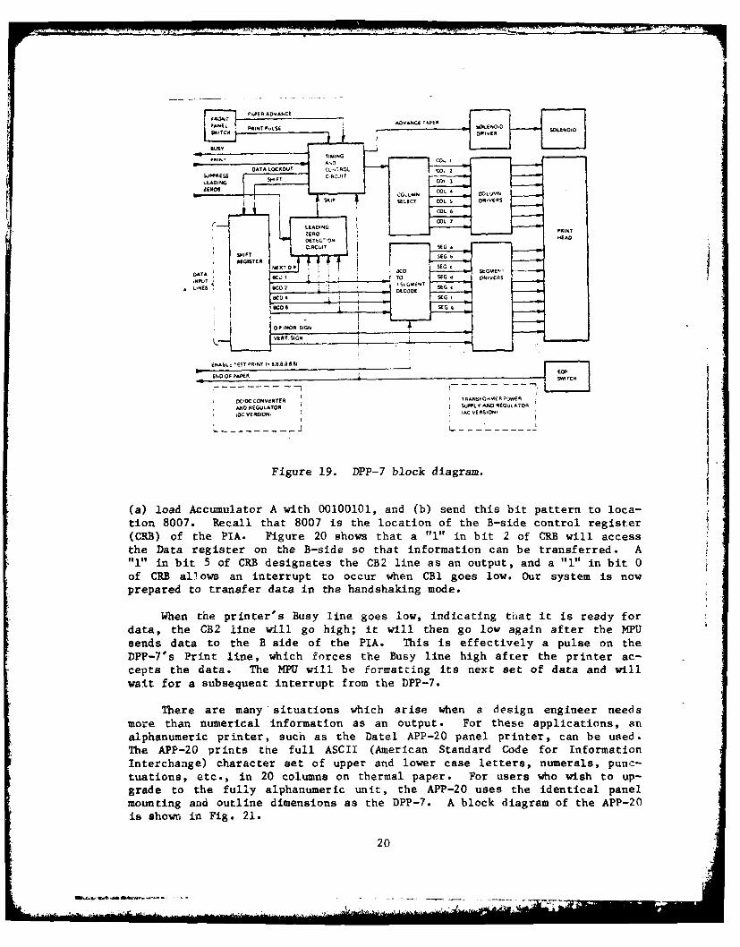
For numerical applications, the Datel DPP-7 digital panel printer(Fig. 18) is a suitable piece of hardware. A block diagram of the printeris shown in Fig. 19. The DPP-7 is a seven-column, panel-mounted terminalwhich can output three lines of data per second. The output data caneither use a leading sign and six-decimal-digits format, or else two lead-ing identifiers and four data digits. The printer accepts 24 input lines,TTL compatible, which can be positive or negative true-level sensitive.The inputs must be full parallel BCD (1-2-4-8) in order to result in six-decimal-digit outputs.
The usual method of interfacing the DPP-7 to a microcomputer is to usehandshaking between the printer and the M1'U. This means that the printerwill inform the HPU when it is ready to accept data, and the MPU will informthe printer when it has Bent the data. Therefore, coordination is total and
16

(a) 30Mz
(b) 40 iMflz
Figure 17. Signal generator outputs.
17

(d) 55 MEt
Figure, !7. Signal generator out puts,.

Figure 18. DPP-7 Digital Panel Printer
complete, and no data will be lost in the process. The control lines of thePIA are used to implement handshaking operations.
The Print and Busy lines of the DPP-7 (Fig. 19) are used to handshakewith the microcomputer. The Busy signal is an output from the printer thatcan be positive or negative TRUE, and it remains TRUE during the print cycle.The data inputs may be changed 500 nanoseconds after transition to TRUE.The next Print command can be enabled when the Busy line goes FALSE. ThePrint signal from the microcomputer must be a pulse that is from I microse-
cond to 200 milliseconds wide. The data to be transferred must be valid fD
nanoseconds before the Print pulse and 1 microsecond after its leading edge.
The actual handshake operation will commence with the DPP-7 sending ahigh-to-low transition on the Busy line to CBI. The PIA informs the M!P1that the printer is ready for data by generating an interrupt on Th& .
Fig. 13). The MPU sends the data out on the data bus and tells the ptin-ter to print, using a pulse of the proper width on CB2 of the PIA. TheCB2 is connected to the Print line of the DPP-7. The printer accepts the
data and pulls the Busy line high while it is printing. Sometime aftersystem initialization, the PIA must be configured properly so that the abovescenario can occur.
As an example, let us assume that the B side of the PIA has already
been designated as all outputs. We must now address the B-side controlregister so that handshaking can take place. We accomplish this as follows:
19
I 7I -. - V
27I
ENO h L T ES E N
E . , PAP R IN U S D A C A E -OI I S LEO ID
SCC... . " .TIMING-- ~DATA LOCKOUT -| CL17ROL 4 Cl
EGLASTOR diRCD:IT
_ _. OIL, ,
Figure 19 P- lokdarm
(C-) fth TA ie 2 shw tata 1"rnSbit 2 of R- il ccs
"1" ~ ~ ~ ~ ~ ~~~SI inEC bitL 5 ofCDesgaesteCIVieasa EutuadRS1 i i
LEA IN COL 7',E PR N
CEDC EAD TE
A,/iO~~~~~N ESUAO i uetYAD "UN OiGCC VII~ i
I T s IEG A ,ON
prepared toumtrasfr A i andakng em d e RI. S
hen0 theprintr's Bu0y line ges lowtindicting t-sat iotris redysfordata, o the CB2 .lie illgo higsh;w it wil then go t l ow agai aftel thessPsed Data togitherBosideof-te PTA th i i srato efctnive anspul ed onthPP1" P it line, whdeichnfaes the CBu line highn ftert the prIin t ac
crepse t dtra.n Te Mat ill e fondsatking itsd extsto.aaadwl
wait for a subsequent interrupt from the DPP-7.
There are many "situations which arise when a design engineer needs
more than numerical information as an output. For these applications, analphanumeric printer, such as the Datel APP-20 panel printer, can be used.
The APP-20 prints the full ASCII (American Standard Code for InformationInterchange) character set of upper and lower case letters, numerals, punc-tuations, etc., in 20 columns on thermal paper. For users who wish to up-grade to the fully alphanumeric unit, the APP-20 uses the identical panelmounting and outline dimensions as the DPP-7. A block diagram of the APP-20is shown in Fig. 21.
20L . . . ...

DATA
PORB CB1 4 BUSY
PRINTER
PIA
CB2 PRINT7 CRB
*A printer request for data MPU SAYS HERE'S NEW DATA
Figure 20. Handshaking with the printer on the "B" side.
This printer is more sophisticated than the numerical printer and ismore difficult to interface to a microcomputer. The difficulties arise insoftware control, however, not in hardware implementation. The input/outputconnection to the APP-20 consists of data and control lines configured on asingle 25-pin type "D" rear connector. The pin connections are listed inTable 1. Seven data inputs select upper and lower case ASCII characters,and the eighth bit designates programmable formatting characters. Addition-al control lines form an interlocked asynchronous handshake to enter eachcharacter into a 20-column input register (Table 2). Characters are loadedsequentially as 8 bits in parallel, and printing begins after all desiredcharacters are loaded into the register. The printing rate is approximate-ly 1-1/2 lines per second.
Table 1. APP-20 I/0 Pin Connection
PIN FUNCTION PIN FUNCTION
14 TextiLister: Norm/InV-tnput) 1 Ready for Data (Output)15 Single Char Print (Input) 2 Data Accepted (Output)16 Tall Characters Input 3 input Register Full (Output)17 Data Valid (Input) 4 Not Used18 Data Bit 2 (Input) 5 +5 Vdc Power Out, .SA max.19 Data Bit 3 (Input) 6 Not Used20 Data Bit 1 (Iput) 7 Logic Ground21 Data Bit 0- LSB (Input) 8 Not Used22 Data Bit 4 (Input) 9 Not Used23 Control Chaoacters - MSB (Input) 10 Not Used24 Data Bit 5 (Input) 11 I Print (Input)25 Data Bit 6 (Input) 12 Data POS/NEG True (Input)
13 End of Paper (Output)
21

Table 2. APP-20 I/O Interface Coanections
No. of
Function Name Lines
Data JASCII characters 7 linesiControl Bit 1 line
{ Data Pos e. True 1 lineMode Inputs ) TexvCister 1 line
(if used, internal SiS e C' i t 1 linepull-ups supplied) Ta Characters 1 line
Handshake Data Valid 1 lineInputs in t 1 lie
TReay for Data 1 lineR egister Full 1 line
Handshake 55Dta Accepted 1 lineOutputs End of Paper 1 line
(Sw to gnd.)
Logic 1 lineGround
The timing and control requirements of the APP-20 are very strict andprecise. A timing diagram for printing one line is shown in Fig. 22. The
hardware interface between the evaluation module and the printer is on a
cable from the 25-pin connector of the APP-20 to the J1 connector of theD2 board. Handshaking takes place with the CBl line of the PIA connected
to DATA ACCEPTED and the CB2 line attached to DATA VALID. The REGISTERFULL output from the printer is connected to its own PRINT input, so thatprinting automatically takes place after 20 characters are input. However,
the number of characters per line must be counted by the MPU. Once the 20
character buffer is full, the REGISTER FULL output pulse will signal thePRINT input, and the actual printing will take place. During this period,
the DATA VALID line will be high (Fig. 22), so that no additional pulses
will interrupt the MPU on CBl.
An APP-20 initialization routine is necessary for power-on reset opera-tion. The MPU informs the printer that the first character is ready to be
loaded by using a DATA VALID falling edge input on CB2, which will load
the data. This is done by configuring the PIA for pulse output operation.
The APP-20 will respond within 300 microseconds with a DATA ACCEPTED output,telling the MPU to update the bus with data for the second character.Prior to this 300-microsecond response, the PIA is reconfigured for hand-
shake operation for the rest of the printing cycle.
Figure 23 describes the method for configuring the PIA for outputtinga pulse to the printer from CB2. A "l" in bit 5 of the CRB designatesCB2 as an output; a "I" in bit 3 of the CRB means pulse mode; and a "i" inbit 2 of the CRB accesses the data register for information transfer. The
output pulse will occur whenever the MPU sends data out to the B side of the
PIA. As an example, let 8006 - B-side Data Register address, and 8007 - B-
side Control Register Address. The procedure would then be as follows:
22
how

0 o
iii
0 il
00
9 Z5
U
1-7.
o 2 we IzN
23.

1. load Accumulator A (LDAA) with 00101100 (2C - the Hexadeci-
mal representation of the binary number), and
2. send the bit pattern in A (STAA) to 8007.
Now the PIA is configured to send a pulse out on the CB2 line wheneverinstructed to do so by the MPU. Suppose the data to be printed were all"l"s; then,
3. LDAA 1111 1111 (FF), and
4. STAA 8006.
As soon as the MPU executes the above statement, the CB2 line, which willnormally be high, goes low on the positive transition of the MPU enablepulse. Then CB2 will go high again on the next positive MPU enable pulsetransition. The net effect is a CB2 pulse, as shown in Fig. 24. Thewidth of the minimum CB2 pulse depends on the width of the enable pulse,which in turn depends on the system clock rate. The clock of the D2 evalua-tion module operates at a 614.4 kHz rate, so the CB2 minimum pulse width isjust under 2 microseconds. The data in the data register of the PIA islatched and available on the first negative transition of the CB2 pulse.The repetition interval between pulses is totally under control of the MPU.One can vary the intervals in software by using different instructions tochange cycle times. This is illustrated in Fig. 25.
h>1 0
_o_ -Est I ' sTE)ovI 519 I$ESET- -1I.
Ohv ~~~.s BEF* [ .-
-- w.i~cts
0- 100( L.",
TIMONCAffIQBN-A.*II I YCi ~P NI [ CII& i,
0, L
L ' IMIN 1 -C 0 ET LEO'V ANI INdM000'1.-C bI O 11.3 0000AN 00
Figure 22. APP-20 timing, printing one line,
24

DATA
PDRB
PIA PRINTER
CB2 -- DATA VALID
7 CRB 0
A Figure 23. ,c utput ,n "B" side configuration.
(a)
(b)
Figure 2', CB2 utPuts in pulse mode.
29r
OA1

The APP-20 printer uses its own internal microprocessor to controldata transfer and printing operations. During the handshake mode, oncethe printer has accepted an ASCII character and the DATA ACCEPTED line goeslow, our system must bring the DATA VALID line high within 45 microseconds.
If not, the APP-20 will poll the DATA VALID line again and load whatever ison the data bus as the next character, whether the bus is ready or not.This 45-microsecond requirement is easily taken care of in software, butthe programmer must always be aware of it.
Data Acquisition Systems
The previous section has described typical printer interfaces formicrocomputer applications. In general purpose computing tasks, the MPUJmay perform sophisticated, mathematical operations and dislay the results,obviating the need for any other input or output interfaces. More oftenthan not, though, the system is connected to the outside world and mustanalyze a particular measurement. 'This is the classic dedicated controlapplication of an MPU-based system. The microcomputer is the controller ofthe experiment and the analyzer of the data it obtains.
Most instruments and sensors of the real world are analog in nature.Microcomputers operate using digitally formatted data. The interface tothe real world, therefore, will involve the analog-to-digital (A/D) conver-sion of information.
Although there are various methods of A/D conversion, each system canusually be divided into two sections; an analog subsystem containing thevarious analog functions for the A/D, and a digital subsystem containingthe digital functions. To add an A/D to the MPU, both of the sectionsmay be added externally to the microprocessor in the form of a PC card,hybrid module, or a monolithic chip.
Two A/D conversion architectures that can be found in 90% of allconverters sold are successive approximation (S/A) and dual-slope integra-tion. The S/A technique uses a digital-to-analog converter (DAC) in afeedback loop to generate a known analog signal to which the unknown analoginput is compared (Fig. 26). The known signal out of the DAC is actually agroup of weighted binary references, equal to the number of bits in the out-put code. The successive approximation method is usually used in high-speedapplications.
The second A/D conversion method, dual slope, is an integration methodin which the conversion is accomplished by first charging an integrator,and then discharging it back to zero. This technique is also called thedual-ramp technique. The ratio in time-of-the-ramp lengths provides avalue representing the difference between a reference and an unknown voltage.
26
(2 7

REFERENCE
, CIRCUIT
rCLOCK
T STORA GE -- -
01 GTAL WORD SERIALPARALLEL OUTPUT OUTPUT
Figure 26. Successive Approximation A/D Converter
The basic waveforms for the dual ramp A/D are shown in Fig. 27. Duringtime period Ti, the unknown input is integrated for a fixed time period(fixed number of clock cycles). The integrator voltage increases from thereference level to a voltage which is proportional to the input voltage.At the end of this time period, a reference voltage is applied to the inputof the integrator, causing the integrator output voltage to decrease untilthe reference level is again reached. The number of clock cycles thatare required to bring the integrator output voltage back to the referencelevel (T2) is proportional to the input unknown voltage. This approach hasa longer conversion time than that of the successive approximation method.However, this method usually performs a more accurate A/D conversion, andat a much lower cost.
The A/D conversion is the heart of a data acquisition system, but itis by no means the only necessary component. Most acquisition systerscontain one or a number of sample-and-hold (S/H) registers to latch analoginformation from a particular source. Also, many systems contain a multi-plexer (MUX), which allows a single interface to access many sources ofdata. The timing and control of all of this hardware can then be provided bya microcomputer.
28

72%in Vro T
Integrator
[a.T1 72
Conrnpawtor
~Ammp
Figure 27. Dual-slope integrating waveform.
The data acquisition system discussed in this report consists of mul-tiple sample and hold circuits feeding a MUX, which in turn transfers theinformation to an A/D converter. Real-world situations require that somesort of signal conditioning is necessary between the S/H and the sensor ortransducer. Usually filters and isolation amplifiers are needed to insurethe proper transfer of data. This aspect of the acquisition process willnot be covered at this time. A key component in our data acquisition sys-tem is the S/H circuit, which is designed to be digitally commanded tooperate in either of two modes: the SAMPLE mode, or the HOLD mode.
In the SAMPLE mode, the S/H circuit output reproduces the input veryclosely; in fact, ideal SAMPLE-mode behavior is characterized by outputtracking and reproducing the ltput perfectly. Figure 28 is the block dia-gram of a typical S/H circuit.
In the HOLD mode, the output maintains very closely the value it hadwhen the S/H received the command on Pin 9 to transfer to the HOLD mode.In practice, the amplifier loads a capacitor, whose output must decay,however slowly. When the capacitance is increased, the decay rate or droopis slowed. However, the acquisition time for a given switch impedance isincreased. The S/H droop rate actually determines how infrequently a chan-nel may be sampled in a system and, therefore, establishes the minimumthroughout. The S/H must hold a sampled signal within +1 LSB (least sig-nificant bit) for as long a time as it takes the A/D converter to convertall other inputs sampled at the same time. A very low initial droop rateis important, since droop is temperature sensitive and typically doublesevery 100 C.
2. Datel/Intersil Engineering Product Handbook 1977, Vol. 3, p 122,(1976-1977).
29i..1 ='--.... .

-ISvDc-, 'OV-.1 BLOCK DIAGRAM - MODEL SHM-4
I EXT. OFFSET ADJ. tOPTIONALI Ad) 11.1 8.0 Out.
" H O L D C A P *,p .t ii d . w '-
ELECTRONIC
*.*-D =ANALOG
J" ~GROUND AAO
SAMPL F 'HOLD SWITCHCON ROL R VER TEST
THRESHOLD 8 7 1s APERTvRE.L. .
.NDAD.. 40P IONALI
Figure 28. SHM-4 sample and hold circuit.
The S/H gain, linearity, noise, and harmonic distortion performanceaffect the system accuracy during the SAMPLE mode. The above parameters
determine the I/0 transfer characteristics while in the tracking phase.The S/H slew rate and settling time affect the system throughput capability,
thus determining a minimum time to be allocated to the acquisition phase.During the S/H transition, the signal being held for conversion may differ
from the signal at the instant of the HOLD command by some error. This is
due to the fact that the S/H requires a finite time in which to open the
switch and to disconnect the input buffer from the holding capacitor. The
error depends upon the dynamics of the signal. During the hold-to-sampletransition, the acquisition time is defined as the amount of time required,from the instant the sample command is given, for the output to first reach
and settle within a stated tolerance. The acquisition time of the S/Haffects the overall system throughput rate and is a measure of the minimumdelay required before conversion can take place for a given input signal.
A MUX is a circuit designed to connect any number of input signal paths
to an output load, switching from path to path in an arbitrary, consecutive,
or changing sequence. This is accomplished in accordance with a digitally
coded "address" instruction from the system program control source (in our
case, the microcomputer). Most MUX modules contain internal decoding cir-
cuitry to convert the binary address input to one-in-four, one-in-eight, or
whatever else is required to switch on one channel at a time. Figure 29
shows a typical N-channel MUX with a single-ended output. Among the key
parameters for MUX selection are: the number of channels, -apability forexpansion, voltage rate for linear operation, and impedance and configura-
tion (single-ended, balanced differential, etc.). Dynamic considerations
include small-signal bandwidth, slew rate, settling time, full-power band-width, and recovery time.
30

CMC
-4N
Figure 29. N-Channel multiplexer circuit.
The A/D converter used in our system is the ADC-149 from Datel3
(Fig. 30). It is a 14-bit successive approximation converter designedmainly for original equipment manufacturer (OEM) uses. It was specificallymade to provide high resolution and accuracy for incorporation into pre-cision instruments for process control systems and test and measurementsystems. The converter accepts either unipolar or bipolar input voltagesand performs a 14-bit conversion in 50 microseconds. Several output codesare available, including straight binary for unipolar inputs, and eitheroffset binary or two's complement for bipolar inputs.
We mentioned in the previous section that the "B" side of a PIA is
normally used to transfer data from a 6800-based system because of thedrive capabilities of the "B" side data and control output lines. We fol-lowed this method for the printer interfaces. Conversely, the "A" sidedata and control lines of the PIA are normally used to input data to thesystem from the outside world. This would be fine for our data acquisitionsystem, if we had an 8-bit A/D converter. Since the ADC-149 is a 14-bitconverter, we shall input data both on the "A" and "B" sides simultan-eously.
Let us assume that our data input system consists of four channels ofinformation feeding four S/H circuits, which In turn are connected to a4-to-1 MUX. The MUX outputs a single channel of information to the ADC-149,which does a conversion in 50 microseconds. Let us now initialize our
3. Datel/Intersil Design Engineers Handbook Goldbook Vol. 3, HaydenPublishing Co., Inc., (1980).
31
i_,

me *Iwoc *.woc GROUND OUTPUT
OUMleT 'Sli M/ J/
MML(..[ CATA OgPTpv
Figure 30. ADC-149 S/A A/D Converter.
microcomputer system to handle the data flow and then to perform the timingand control functions.
Since this particular application requires the movement of more thaneight bits of information at one time, we implement a change in the address-
ing scheme of the particular PIA in use. We normally tie the RSO line toA0 of the address bus, and RSl to Al (Fig. 13). For this case, we reversethe connections so that RS0 is connected to Al and RSI to AO. This willplace the peripheral data registers and control registers side by side in
the memory map as follows:
8004 = A-side Data Register,8005 B-side Data Register,
8006 -A-side Control Register (CRA) and
8007 B-side Control Register (CR).
~The 16-bit index register CX) can now be used to transfer data with oneinstruction, instead of the 8-bit accumulator (A). We shall use a secondPlA, conventionally addressed, to maintain timing and control of the S/Hcircuits and the 1IUX. This PIA occupies addresses 8020-8024. Let us ini- -tiate our system by clearing bit 2 of the PIA control registers to accessthe data direction registers. Recall that "l"s will designate outputs, and"0", inputs; then
32I" A.
. .
GR!k

LDAA 00,
STAA 8006 Clear CRA (PIAl),
STAA 8007 Clear CRB (PIAI),
STAA 8021 Clear CRA (PIA2) and,
STAA 8023 Clear CRB (PIA2).
Now that we have accessed the data direction registers, let us designate theinputs and outputs. Thus,
LDX 0000 (all "O"s i.e., all inputs),
STX 8004 (loads A&B direction registers for A/D),
LDAA FF (all "l"s i.e., ourtuts), and
STAA 8022 (loads B direction register).
The last statement designates the B side of PIA2 as all outputs. Wewill use these lines to control the S/H circuits and the MUX.
We have finished determining the direction of our flow of information,so we now set bit 2 of the control registers to access the Data Register.Therefore,
LDAA 04 (i.e., 0000 0100 - set Bit 2),
STAA 8006 (Bit 2 set for CRA of PIAl),
STAA 8007 (Bit 2 set for CRB of PlAl), and
STAA 8023 (Bit 2 set for CRB of PIA2).
Like many other peripheral circuits, the ADC-149 converter should exchangedata with the MPU in a handshaking mode. For this case, the A/D convertershould signal that it has accepted the data. Figure 31 shows the correct PIAconfiguration for transferring data from a peripheral to the MPU, usinghandshaking. The CA2 line of the PIA is connected to the A/D converter's"start of conversion" line, and the CA1 line is connected to the "endof conversion" line, so
LDAA 25 (i.e., 0010 0101) and,
STAA 8006 ("A" side handshake),
33

~DATA[
PDRA NEW DATA
CA1 READY EOC
A/D
PIA CONVERTER
CA2 SOC
7 CRA 0
057 01 0 i 01 01 11
DATA ACCEPTEDLDX 8004
Figure 31. Handshaking with peripheral on "B" side.
When the ADC-149 has completed a conversion it will send out a high-to-low transition to CAl, which will cause an interrupt of the MPU. The MPUwill then output a low-to-high transition on CA2, telling the ADC-149 tostart the next conversion. The CA2 line will go low again after the dataon the "A" side has been read by the MPU, i.e.,
LDX 8004 (Read 16 bits; data accepted).
We are now able to input digital data from the converter, but we mustalso determine the correct procedure for doing so. Let us designate thefour S/H circuits as SH1 to SH4. From Fig. 28 we see ihat a zero on pin9 means sample, and a one means hold. If each of the control lines is tiedto A-side data lines PAO-PA3 (Fig. 15) of PIA2, we can easily control the S/Hcircuits by sending zeros or ones out from the MPU. For example, if wewish SH1 to SH4 to all sample simultaneously, then
LDAA XXXXOOOO all zeros (X-represents a "don't care" condition), and
STAA 8020 (all 4 sample mode).
34

Also, if we wanted SHi to sample and the rest to hold, then
LDAA XXXXIII0, and
STAA 8020 (SHI samples, rest hold).
In a similar manner, we can control the channel selection of the MUX by
inputting the proper values of ones and zeroes on CAl and CA2 (Fig. 31).Table 3 gives the channel addressing for an MX-409 4-to-l MUX.
TABLE 3. MUX CHANNEL ADDRESSING
Inhibit CA2 CAl ON CHANNEL
0 X X None
1 0 0 1
1 0 1 2
1 1 0 3
1 1 1 4
Suppose that CAl, CA2, and inhibit were connected to PA4, PA5, and PA6,respectively. Now let us sample all four S/H circuits simultaneously whileinhibiting the MUX.
LDAA MOXX 0000 Sample all, and
STAA 8020 (inhibit MUX).
If we wish to latch the data for all channels and choose, say chan-nel 3, to put through the MUX, then
LDAA X1101111, and
STAA 8020 (hold all, pick CH3).
In order to convert the value from channel 3, we would now send out astart of-conversion pulse to the ADC-149 and wait at least 50 microsecondsfor the end-of-conversion pulse, then read the digital data as previouslydescribed. It's easy to see that the microcomputer can maintain total
control of the data collection process. Once the digital information is
35

acquired, it can be processed and then outputted to a display or printingmechanism through an interface, as described in the previous section.
CONCLUSIONS
The important factor in interfacing a Motorola 6800 microprocessor tothe outside world is through a thorough understanding of the requirementsof the Peripheral Interface Adapter integrated circuit. Proper addressingand control of this IC will enable a system designer to implement manydifferent interfacing techniques.
The PIA was configured for a particular system by accessing its inter-nal registers. The data registers, control registers, and data-directionregisters were accessed by using a specific set of assembly language in-structions. These instructions allowed information transfer along thesystem data bus to the addresses occupied by the PIA.
The signal generator, printers, and data acquisition system were all.tied to the output lines of a single PIA or multiple PIA's. Hardware re-quirements of these external devices are the same, but the number of linesrequired by each is different; i.e., they each require their own type ofMPU instructions for a specific PIA configuration. However, the addressrequirements of the PTA's themselves remain the same. The transfer ofdata to and from the processor is then reduced to writing and executing acontrol program.
36

BIBLIOGRAPHY
L. Leventhal, L.A., 6800 Assembly Language Programming, Osborne &Associates, Inc., Berkeley, CA, 1978.
2. Lesea A., and Zaks, R. A., Microprocessor Interface Techniques, Sybex
Inc., 1978.3. M6800 Microprocessor Applications Manual, Motorola Semiconductor
Products, Inc., McGraw Hill, NY, 1975.4. M6800 Microprocessor Programming Manual, Motorola Inc., 1975.5. Osborne, A., An Introduction to Microcomputers, Vol 0, Osborne &
Associates, Inc., Berkeley, CA., 1976.6. Peatman, John B., Microcomputer Based Design, McGraw Hill, NY, 1977.7. Hilburn, J., and Julich, P., Microcomputer/Microprocessors Hardware,
Software and Applications, Prentiss Hall, Englewood Cliffs, NJ, 1976.8. Datel/Intersil Engineering Product Handbook Gold Book 1979/1980,
Vol 3, Hayden Publishing Company.
HISA-FM 1365-8037