a 58-63.6ghz quadrature pll frequency … 58-63.6ghz quadrature pll frequency synthesizer in 65nm...
TRANSCRIPT

A 58-63.6GHz Quadrature PLL FrequencySynthesizer in 65nm CMOS
Ahmed Musa, Rui Murakami, Takahiro Sato, Win Chiavipas, Kenichi Okada and Akira MatsuzawaDept. Physical Electronics, Tokyo Institute of Technology
2-12-1-S3-27, Ookayama, Meguro-ku, Tokyo 152-8552 Japan.Tel: +81-3-5734-3764, Fax: +81-3-5734-3764, E-mail: [email protected]
Abstract—This paper proposes a 60GHz quadrature PLLfrequency synthesizer that has a tuning range capable of coveringthe whole band specified by the IEEE802.15.3c with exceptionalphase noise. The synthesizer is constructed using a 20GHz PLLthat is coupled with a frequency tripler to generate the 60GHzsignal. The 20GHz PLL generates a signal with a phase noiseas low as −106dBc/Hz using tail feedback to improve the phasenoise. The proposed 60GHz ILO uses a combination of paralleland tail injection to enhance the locking range by reducing theInjection Locked Oscillator (ILO) current at the moment ofinjection. Both the 20GHz PLL and the ILO were fabricatedusing a 65nm CMOS process and measurement results show aphase noise of −96dBc/Hz at 60GHz while consuming 77.5mWfrom a 1.2V supply. To to author’s knowledge this phase noise isabout 20dB better then recently reported QPLL and about 10dBcompared to differential PLL operating at similar frequency.
I. Introduction
Recently, the demand for high data rate wireless communi-cation is increasing to serve applications like high definitionvideo and multimedia applications. One way to serve this de-mand was by introducing more complex modulation schemesto increase the throughput. However, phase noise, powerconsumption and affordability puts an upper limit on the per-formance gain achievable. To overcome these limitations, oneof the promising solutions is to utilize the 60GHz ISM bandfor high-speed short-range data communication. As defined bythe IEEE802.15.3c standard, the band covers the range from57-66GHz and has four channels each with a bandwidth of2.16GHz. This bandwidth enables wireless Gbps transfer rateswhich makes this band very appealing as a next generationwireless standard. Moreover, using an affordable process likeCMOS further enhances the advantages of this band speciallysince, due to miniaturization, CMOS transistors can operateup to a few hundred GHz. Still, a CMOS process has manychallenges like higher process variations, lower mobility andlower breakdown voltage which limits the performance andrequires novel designs to overcome these obstacles.The LO frequency synthesizer is the heart of most moderntransceivers and plays an important role in setting the finalperformance. In a synthesizer, the VCO phase noise setsthe limit on the usable modulation scheme and transfer rate.Therefore, lowering the phase noise will enable more complexmodulation schemes and thus faster data rate. However, tolower the phase noise a higher Q is required but due to
Phase
Frequency
Detector
Charge Pump
Low
Pass
Filter
CML ÷4÷5÷(30,29,28,27)
S1 S0
Digital
Divider
Analog
Divider
19.44GHz
20.16GHz
20.88GHz
21.60GHz
VCO60GHz Injection
Locked Oscillator
58.32GHz 60.48GHz 62.64GHz 64.80GHz
INEG IPOSQNEGQPOS
Reference
Frequency
(36MHz)
Fig. 1. The proposed 60GHz synthesizer architecture
large tuning range for the 60GHz band a high FrequencyTuning Range (FTR) is required. Therefore, a wide range ofcapacitance is needed, which lowers the quality factor sincecapacitors have significantly lower Q at 60GHz compared tolower frequencies. One solution could be to use two VCOs [1]but due to poor quality factor of the capacitors, the resultingphase noise is not greatly improved compared to a singleVCO structure. Another can use a push-push oscillator werefrequency is generated at half [2] [3] or one third [4] andthen combined to cancel the first in case of a VCO runningat half the required frequency or both the first and second incase of a VCO running at one third the frequency. This paperuses a third way in which the frequency is generated at asubharmonic and a frequency multiplier is used to lock to thethird harmonic and generate the desired signal in which thephase noise of the up-converted signal depends on the injectedsignal which can be generated with a low phase noise. Inthe proposed synthesizer, The VCO employs tail feedback toimprove phase noise [5] and the Injection Locked Oscillator(ILO) uses both parallel and tail injection to enhance locking.
II. 60GHz LO Synthesizer Architecture
There are many LO synthesizer architectures availablewhen it comes to a direct conversion receiver for a 60GHztransceiver. Each architecture has its advantages in termsof complexity, area, attainable phase noise, and power con-sumption. Mainly, three main approaches to design the LOsynthesizer for a direct 60GHz transceiver are used which areusing a VCO running at the fundamental frequency [1] [6][7], a push-push VCO to generate the frequency at half orone third and then combining the generated signals to cancelthe first or first and second harmonic respectively and finallyusing a subharmonic VCO with a frequency multiplier.
A. Fundamental
Designing a VCO running at 60GHz while having a widetuning range and low phase noise is as mentioned before verychallenging because of the low Q of the capacitors at such highfrequency which severely degrades the phase noise and thusdata-rate. Also, tuning range is needed to be made much widerthen the required one since the VCO is extremely sensitiveto parasitics and it is highly likely for the frequency to driftby a considerable amount due to layout parasitics. Finally,designing a divider to operate at this high frequency wouldbe difficult and would result in a high power consumptionspecially for an inductorless one.
B. Push-Push
Although a push-push oscillator is running at a half [2] [3]or [4] one third of the required frequency and thus requirehalf or one third the required tuning range, its output power islargely compromised due to cancellation of the fundamentalharmonic and the use of the second or third harmonic instead.This would require additional amplifications in the buffersthat will increase the power consumption. Furthermore, IQgeneration is difficult and will require additional circuitrywhich will introduce a significant loss and mismatch wouldneed to be given extra care to reduce the IQ mismatch asmuch as possible.
C. Subharmonic VCO and Injection Locked Oscillator (ILO)
The third way would be to use a subharmonic VCO and aninjection locked oscillator [8] to super-harmonically lock to theVCO and generate the LO signal. This way would benefit fromthe lower frequency generation and narrower tuning range butthe fundamental would not be cancelled for generating thehigher harmonic instead it will be injected to the ILO. The ILOon the other hand can be designed to have a very wide tuningrange without paying much attention to lowering the phasenoise since the output phase noise is determined by the lockingsignal’s phase noise. The drawback would be the amount ofpower that the multiplier needs to lock. The proposed systemis based on this concept as show in Fig. 1 in which the systemconsists of a 20GHz PLL that is injection locked to an ILOfrequency tripler.
III. 20GHz PLL Synthesizer
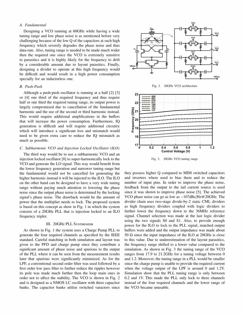
As shown in Fig. 1 the system uses a Charge Pump PLL togenerate the four required channels as specified by the IEEEstandard. Careful matching in both simulation and layout wasgiven to the PFD and charge pump since they contribute asignificant amount of phase noise and spurious to the outputof the PLL where it can be seen from the measurement resultslater that spurious were significantly minimized. As for theLPF, a conventional second order filter was used followed by afirst order low pass filter to further reduce the ripples howeverits pole was made much further then the loop main ones inorder not to affect the stability. The VCO is shown in Fig. 2and is designed as a NMOS LC oscillator with three capacitorbanks. The capacitor banks utilize switched varactors since
VDD
LP
CP
CF CF
VBias
Vs3
Vs3
Vs2
Vs2
Vs1
Vs1
Vctrl
VBias
Fig. 2. 20GHz VCO architecture
0 0.2 0.4 0.6 0.8 1 1.2Control Voltage (V)
17
18
19
20
21
22
23
Frequency (GHz)
000001010011100101110111
Fig. 3. 20GHz VCO tuning range
they possess higher Q compared to MIM switched capacitorsand inverters where used to bias them and to reduce thenumber of input pins. In order to improve the phase noise,feedback from the output to the tail current source is usedsince it was shown to improve phase noise [5]. The achievedVCO phase noise can go as low as −107dBc/Hz@20GHz. Thedivider chain uses two-stage divide-by-2 static CML dividersas high frequency dividers coupled with logic dividers tofurther lower the frequency down to the 36MHz referencesignal. Channel selection was made at the last logic dividerusing the two signals S0 and S1. Also, to provide enoughpower for the ILO to lock to the PLL signal, matched outputbuffers were added and the output impedance was made about50 Ω since the input impedance of the ILO at 20GHz is closeto this value. Due to underestimation of the layout parasitics,the frequency range shifted to a lower value compared to thesimulation. As shown in Fig. 3 the tuning range of the VCOranges from 17.9 to 21.2GHz for a tuning voltage between 0and 1.2. Moreover, the tuning range in a PLL would be smallersince the charge pump is unable to provide the required currentwhen the voltage output of the LPF is around 0 and 1.2V.Simulation show that the PLL tuning range is only between0.2 and 1V. This made the PLL only lock to three channelsinstead of the four required channels and the lower range ofthe VCO became unusable.
IV. The Proposed 60GHz Injection Locked Ocillator
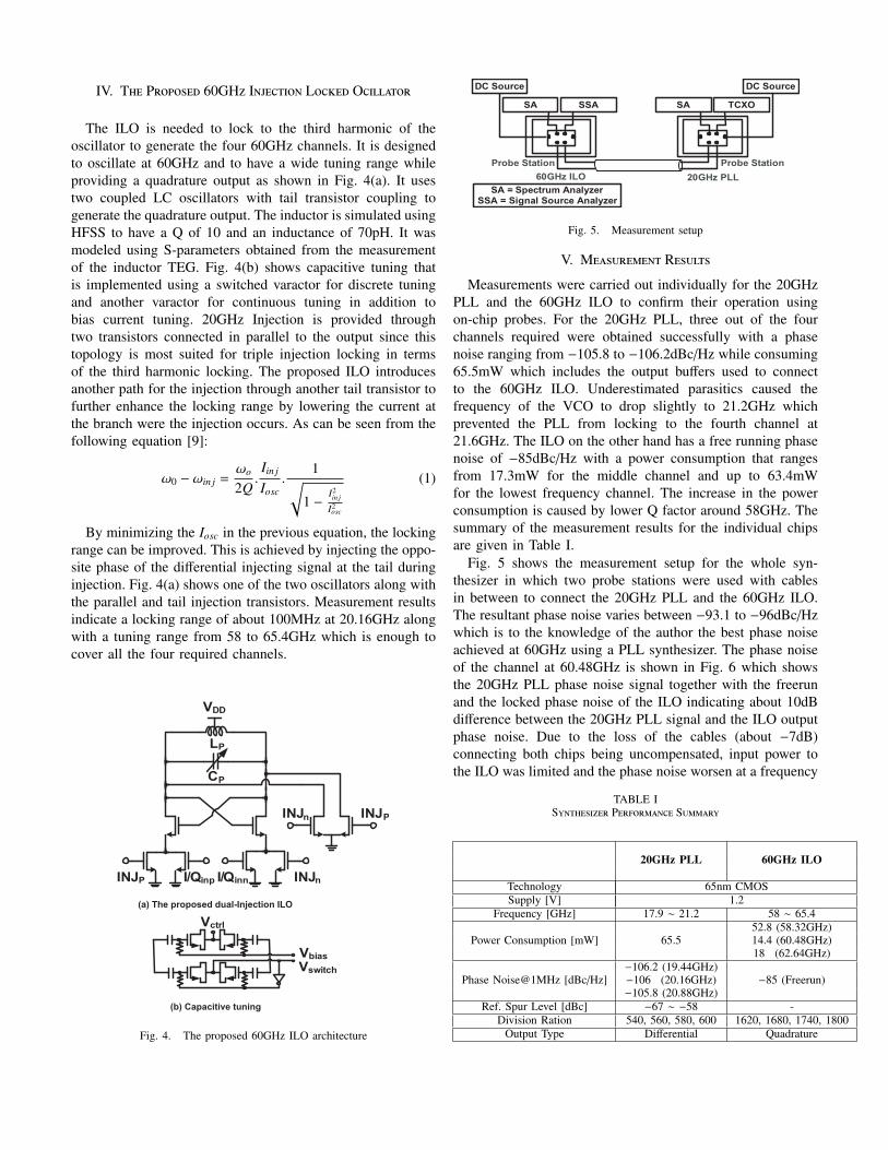
The ILO is needed to lock to the third harmonic of theoscillator to generate the four 60GHz channels. It is designedto oscillate at 60GHz and to have a wide tuning range whileproviding a quadrature output as shown in Fig. 4(a). It usestwo coupled LC oscillators with tail transistor coupling togenerate the quadrature output. The inductor is simulated usingHFSS to have a Q of 10 and an inductance of 70pH. It wasmodeled using S-parameters obtained from the measurementof the inductor TEG. Fig. 4(b) shows capacitive tuning thatis implemented using a switched varactor for discrete tuningand another varactor for continuous tuning in addition tobias current tuning. 20GHz Injection is provided throughtwo transistors connected in parallel to the output since thistopology is most suited for triple injection locking in termsof the third harmonic locking. The proposed ILO introducesanother path for the injection through another tail transistor tofurther enhance the locking range by lowering the current atthe branch were the injection occurs. As can be seen from thefollowing equation [9]:
ω0 − ωin j =ωo
2Q.Iin j
Iosc.
1√1 −
I2in j
I2osc
(1)
By minimizing the Iosc in the previous equation, the lockingrange can be improved. This is achieved by injecting the oppo-site phase of the differential injecting signal at the tail duringinjection. Fig. 4(a) shows one of the two oscillators along withthe parallel and tail injection transistors. Measurement resultsindicate a locking range of about 100MHz at 20.16GHz alongwith a tuning range from 58 to 65.4GHz which is enough tocover all the four required channels.
LP
CP
VDD
INJP INJnI/Qinp I/Qinn
INJPINJn
Vctrl
Vswitch
Vbias
(a) The proposed dual-Injection ILO
(b) Capacitive tuning
Fig. 4. The proposed 60GHz ILO architecture
20GHz PLL
DC Source
60GHz ILO
TCXOSASSASA
DC Source
SA = Spectrum AnalyzerSSA = Signal Source Analyzer
Probe Station Probe Station
Fig. 5. Measurement setup
V. Measurement Results
Measurements were carried out individually for the 20GHzPLL and the 60GHz ILO to confirm their operation usingon-chip probes. For the 20GHz PLL, three out of the fourchannels required were obtained successfully with a phasenoise ranging from −105.8 to −106.2dBc/Hz while consuming65.5mW which includes the output buffers used to connectto the 60GHz ILO. Underestimated parasitics caused thefrequency of the VCO to drop slightly to 21.2GHz whichprevented the PLL from locking to the fourth channel at21.6GHz. The ILO on the other hand has a free running phasenoise of −85dBc/Hz with a power consumption that rangesfrom 17.3mW for the middle channel and up to 63.4mWfor the lowest frequency channel. The increase in the powerconsumption is caused by lower Q factor around 58GHz. Thesummary of the measurement results for the individual chipsare given in Table I.
Fig. 5 shows the measurement setup for the whole syn-thesizer in which two probe stations were used with cablesin between to connect the 20GHz PLL and the 60GHz ILO.The resultant phase noise varies between −93.1 to −96dBc/Hzwhich is to the knowledge of the author the best phase noiseachieved at 60GHz using a PLL synthesizer. The phase noiseof the channel at 60.48GHz is shown in Fig. 6 which showsthe 20GHz PLL phase noise signal together with the freerunand the locked phase noise of the ILO indicating about 10dBdifference between the 20GHz PLL signal and the ILO outputphase noise. Due to the loss of the cables (about −7dB)connecting both chips being uncompensated, input power tothe ILO was limited and the phase noise worsen at a frequency
TABLE ISynthesizer Performance Summary
20GHz PLL 60GHz ILO
Technology 65nm CMOSSupply [V] 1.2
Frequency [GHz] 17.9 ∼ 21.2 58 ∼ 65.452.8 (58.32GHz)
Power Consumption [mW] 65.5 14.4 (60.48GHz)18 (62.64GHz)
−106.2 (19.44GHz)Phase Noise@1MHz [dBc/Hz] −106 (20.16GHz) −85 (Freerun)
−105.8 (20.88GHz)Ref. Spur Level [dBc] −67 ∼ −58 -
Division Ration 540, 560, 580, 600 1620, 1680, 1740, 1800Output Type Differential Quadrature
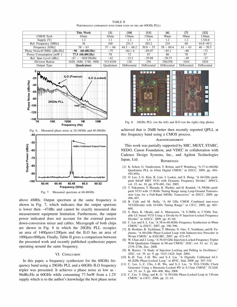
TABLE IIPerformance comparison with other state-of-the-art 60GHz PLLs
This Work [1] [10] [11] [6] [7] [12]CMOS Tech 65nm 45nm 130nm 130nm 90nm 90nm 130nmSupply [V] 1.2 1.1 1.2 1.5 1.2 1.2 1.5/0.8
Ref. Frequency [MHz] 36 100 251.3 203.2 234 60 44.8∼49.3Frequency [GHz] 58 ∼ 63 57 ∼ 66 64.3 ∼ 66.2 50.8 ∼ 53 58 ∼ 60.4 61 ∼ 63 46 ∼ 50.5
Phase Noise@1MHz [dBc/Hz] −96 (60.48GHz) −75 −84.1 6 −85.07 −85.1 −80 −72Power Consumption [mW ] 77.5 (60.48GHz) 78 72 87 80 78 57
Ref. Spur Level [dBc] −67 ∼ −58@20GHz −42 −15.2 −59.88 −50.75 −49 −27Division Ration 1620, 1680, 1740, 1800 512-8184 128 256 256/258 1024 1024
Output Type Quadrature Quadrature Differential Differential Differential Differential Differential
1K 10K 100K 1M 10MFrequency (Hz)
-140
-120
-100
-80
-60
-40
-20
0
Phase Noise (dBc/Hz)
ILO (Freerun)ILO (Locked)
20GHz PLL
10dB
Fig. 6. Measured phase noise at 20.16GHz and 60.48GHz
60.44 60.46 60.48 60.5 60.52Frequency (GHz)
-100
-90
-80
-70
-60
-50
-40
Output Power (dBm)
-6dBm Calibrated Output Power
Fig. 7. Measured spectrum at 60.48GHz
above 4MHz. Output spectrum at the same frequency isshown in Fig. 7, which indicates that the output spuriousis lower then −47dBc and cannot be exactly measured duemeasurement equipment limitation. Furthermore, the outputpower indicated does not account for the external passivedown-conversion mixer and cables. Micrograph of both chipsare shown in Fig. 8 in which the 20GHz PLL occupiesan area of 1400µm×1200µm and the ILO has an area of1000µm×800µm. Finally, Table II gives a comparison betweenthe presented work and recently published synthesizer papersoperating around the same frequency.
VI. Conclusion
In this paper, a frequency synthesizer for the 60GHz fre-quency band using a 20GHz PLL and a 60GHz ILO frequencytripler was presented. It achieves a phase noise as low as -96dBc/Hz at 60GHz while consuming 77.5mW from a 1.2Vsupply which is to the author’s knowledge the best phase noise
Fig. 8. 20GHz PLL (on the left) and ILO (on the right) chip photos
achieved that is 20dB better then recently reported QPLL atthis frequency band using a CMOS process.
Acknowledgment
This work was partially supported by MIC, MEXT, STARC,NEDO, Canon Foundation, and VDEC in collaboration withCadence Design Systems, Inc., and Agilent TechnologiesJapan, Ltd. References[1] K. Scheir, G. Vandersteen, Y. Rolain, and P. Wambacq, “A 57-to-66GHz
Quadrature PLL in 45nm Digital CMOS,” in ISSCC, 2009, pp. 494–495,495a.
[2] O. Lee, J.-G. Kim, K. Lim, J. Laskar, and S. Hong, “A 60-GHz push-push InGaP HBT VCO with Dynamic Frequency Divider,” MWCL,vol. 15, no. 10, pp. 679–681, Oct. 2005.
[3] T. Nakamura, T. Masuda, K. Washio, and H. Kondoh, “A 59GHz push-push VCO with 13.9GHz Tuning Range using Loop-Ground Transmis-sion Line for a Full-Band 60GHz Transceiver,” in ISSCC, 2009, pp.496–497.
[4] B. Catli and M. Hella, “A 60 GHz CMOS Combined mm-waveVCO/Divider with 10-GHz Tuning Range,” in CICC, 2009, pp. 665–668.
[5] S. Hara, K. Okada, and A. Matsuzawa, “A 9.3MHz to 5.7GHz Tun-able LC-based VCO Using a Divide-by-N Injection-Locked FrequencyDivider,” in ASSCC, 2009, pp. 81–84.
[6] C. Lee and S. L. Liu, “A 58-to-60.4GHz Frequency Synthesizer in 90nmCMOS,” in ISSCC, 2007, pp. 196–596.
[7] H. Hoshino, R. Tachibana, T. Mitomo, N. Ono, Y. Yoshihara, and R. Fu-jimoto, “A 60-GHz Phase-Locked Loop with Inductor-less Prescaler in90-nm CMOS,” in ESSCIRC, 2007, pp. 472–475.
[8] W. Chan and J. Long, “A 56-65 GHz Injection-Locked Frequency TriplerWith Quadrature Outputs in 90-nm CMOS,” JSSC, vol. 43, no. 12, pp.2739–2746, Dec. 2008.
[9] B. Razavi, “A Study of Injection Locking and Pulling in Oscillators,”JSSC, vol. 39, no. 9, pp. 1415–1424, Sept. 2004.
[10] K.-H. Tsai, J.-H. Wu, and S.-I. Liu, “A Digitally Calibrated 64.3-66.2GHz Phase-Locked Loop,” in RFIC, June 2008, pp. 307–310.
[11] C. Lee, L.-C. Cho, J.-H. Wu, and S.-I. Liu, “A 50.8–53GHz ClockGenerator Using a Harmonic-Locked PD in 0.13um CMOS,” TCASII,vol. 55, no. 5, pp. 404–408, May 2008.
[12] C. Cao, Y. Ding, and K. O, “A 50-GHz Phase-Locked Loop in 130-nmCMOS,” in CICC, 2006, pp. 21–24.