a 12 sector space vector switching scheme for performance ... · sensor-less matrix converter...
TRANSCRIPT

0885-8993 (c) 2013 IEEE. Translations and content mining are permitted for academic research only. Personal use is also permitted, but republication/redistribution requires IEEEpermission. See http://www.ieee.org/publications_standards/publications/rights/index.html for more information.
This article has been accepted for publication in a future issue of this journal, but has not been fully edited. Content may change prior to final publication. Citation information: DOI10.1109/TPEL.2014.2347457, IEEE Transactions on Power Electronics
> IEEE TRANSACTIONS ON POWER ELECTRONICS, VOL. XX, NO. XX, XXXX XXXX<
1
Abstract— This paper presents a direct torque control (DTC)
switching scheme based on direct matrix converter (DMC) using
12-side polygonal space vector for variable speed control of an
induction motor (IM). The conventional DTC scheme based
matrix converter (MC) is limited by 60°sectors of both flux and
voltage vectors which introduce high torque ripple. The proposed
method utilizes twelve 30°sectors of both flux and voltage vectors
to increase the degrees of freedom for selection of proper vectors
and reduce the torque ripple. The proposed switching scheme for
MC based DTC of IM drive select the appropriate switching
vectors for control of torque with small variations of the stator
flux within the hysteresis band. This improves the degrees of
freedom in selecting the vector algorithm and the torque ripple
as well. Furthermore, during the large torque demand, the
probabilities of transgressing reference vector limits, which are
enclosed by 12-side polygonal space vector, are reduced.
Extensive simulation and experimental results are presented to
verify the effectiveness of the 12-sector space vector switching
scheme for DTC of IM fed by DMC.
Index Terms—Matrix Converter, direct torque control,
induction motor, space vector, switching scheme, torque ripple.
I. INTRODUCTION
he requirement of torque control to adjust the speed in
industrial applications resulted in the high demand for a
controlling scheme with fast transient , less torque ripple
and accurate control of torque for an induction motor (IM)
with compact and high reliability adjustable speed drive [1].
Manuscript received March 14, 2014; revised April 29, 2014; accepted July
30, 2014. Date of publication XXXXXX; date of current version XXXXXX. This work was supported by the High Impact Research of University of
Malaya–Ministry of Higher Education of Malaysia under Project UM.C/
HIR/MOHE/ENG/24. S. Sina Sebtahmadi and S. Mekhleif are with the Power Electronics and
Renewable Energy Research Laboratory (PEARL), Department of Electrical
Engineering, University of Malaya, 50603 Kuala Lumpur, Malaysia (e-mail: [email protected] ; [email protected]).
Hossein Pirasteh and Ahmad Radan are with the Faculty of Electrical and
Computer Engineering, K. N. Toosi University of Technology, Tehran, Iran (e-mail: [email protected] ; [email protected] ).
S.Hr. Aghay Kaboli is with the UM Power Energy Dedicated Advanced
Centre (UMPEDAC),University of Malaya, Kuala Lumpur, Malaysia (e-mail:
Color versions of one or more of the figures in this paper are available
online at http://ieeexplore.ieee.org. Digital Object Identifier XXXXXXX.
A 12-Sector Space Vector Switching Scheme
for Performance Improvement of Matrix
Converter Based DTC of IM Drive
S. Sina Sebtahmadi, Member, IEEE, Hossein Pirasteh, S.Hr. Aghay Kaboli, Ahmad Radan, Member,
IEEE, S. Mekhleif, Senior Member, IEEE
Hφ Flux hysteresis output controller
HTe Torque hysteresis output controller
K Flux vector sector number
L Voltage vector sector number
Lm Mutual inductance
Lr Rotor leakage inductance
Ls Stator leakage inductance
P Number of poles
Sk Switching states
Te Electromagnetic torque of the induction machines
eT Torque command
ΔTe Variation of electromagnetic torque
ΔTe, pu Torque variation in per unit
Vm Rated voltage
Vsm1 Minimum vector voltage for conventional (60°)
scheme
Vsm2 Minimum voltage vector for proposed (30°)
scheme
Vsr & Vst Radial and tangential components of stator-voltage
space vector
sV
Stator-voltage space vector
Vsα & Vsβ α and βcomponents of stator voltage, respectively
k1 & k2 Flux and torque variation coefficient, respectively
kT Constant value
t0 Initial time
Δt Time interval
v+1 &v-1 Voltage vector first order in (+)ve and (-)ve
regions, respectively
α & β Real and imaginary components of the transformation
from 3-phase stationary coordinate system to the 2-
phase coordinate system
γ Load angle
γ1 Angle between stator and rotor-flux vectors
Δγ Variation of load angle
Δζ Variation of rotor-flux vector angle
θ Angle of stator-flux vector
Δθ Variation of stator-flux vector angle
σ Leakage factor
ψm Maximum flux of stator
sψ
Stator-flux vector
rψ
Rotor-flux vector
sψ Stator-flux command
sψ Stator-flux vector variation
pusψ
Stator flux variation in per unit
ωs Synchronous speed
Note: all the motor parameters are referred to stator side.
T

0885-8993 (c) 2013 IEEE. Translations and content mining are permitted for academic research only. Personal use is also permitted, but republication/redistribution requires IEEEpermission. See http://www.ieee.org/publications_standards/publications/rights/index.html for more information.
This article has been accepted for publication in a future issue of this journal, but has not been fully edited. Content may change prior to final publication. Citation information: DOI10.1109/TPEL.2014.2347457, IEEE Transactions on Power Electronics
> IEEE TRANSACTIONS ON POWER ELECTRONICS, VOL. XX, NO. XX, XXXX XXXX<
2
A matrix converter (MC) enables control of torque and flux
via various vector-selection criteria give rise to various
switching strategies, each affecting drive torque ripple, current
ripple, and switching frequency. The MC has been an apposite
candidate for interfacing of two ac systems with a compact
and reliable design [2] as compared to the voltage source
inverters (VSI) which conventionally are utilized to drive IM
[3]. In addition, the matrix converter has a long lifetime and
can operate in hostile environments due to absence of dc-link
electrolytic capacitors [4], these features of matrix converter
could offer advantages in military [5], transportation,
renewable energy [6] and aerospace applications, where
weight, volume and reliability are important criteria [7].
While, the researches chiefly concern direct matrix
converters (DMC) an indirect matrix converter (IMC) can be
considered as an option for the DMC [8, 9]. Still, the main
circuit of the IMC has drawbacks compared to the DMC, eg.
power losses of the IMC are larger with most loading
situations. In addition, its output/input voltage ratio is more
non-linear than the ratio of the DMC, which reduces its
suitability to the speed sensor-less drive of IM [10]. One of the
biggest difficulties in the operation of this converter was the
commutation of the bidirectional switches. This problem has
been solved by introducing intelligent and soft commutation
techniques, giving new momentum to research in this area,
while with a suitable modulation method there is no need for
special commutation methods of MCs [11]. The most relevant
modulation methods developed up to now, for the MC, are the
scalar techniques and pulse width modulation methods
(PWM). These MC modulations are efficient, but complex to
understand, and synthesize compared to the three phase VSI
modulations, thereby heavy to implement in digital processors.
An alternative solution conventionally in use is to apply space
vector modulation (SVM) for MCs [3, 12-14].
The two elegant and powerful controlling methods currently
are used to control the speed of IM fed by MC, are field
oriented control (FOC) and direct torque control (DTC). The
advantages of DTC are no requirements for coordinate
transformations and decoupling processes for both voltage and
currents, robust and fast torque response, robustness against
parameter variation, no requirements for PWM pulse
generation and current regulators [15]. However, the main
drawback of the DTC scheme is the high current and torque
ripple. The disadvantages of DTC scheme also include
variable switching frequency, and difficult-to-control torque
and flux at very low speeds [16]. In the conventional DTC the
circular locus is divided into 6 sectors and a total of 8 voltage
vectors are used. However, the discrete inverter switching
vectors cannot always generate exact stator voltage required to
obtain the demanded electromagnetic torque and stator flux
linkages. This results in production of ripples in the flux as
well as torque.
The researchers have reported various voltage-vector-
selection strategies for matrix converter based DTC scheme
[17-19]. The advantages of the matrix converter were
combined with the advantages of the DTC schemes in [17].
The use of matrix converter input voltages with different
amplitudes in order to reduce the inherent torque ripple that
appears when direct torque control is applied to drive PMSM
was investigated in [18]. An improved DTC-SVM method for
sensor-less matrix converter drives using an over modulation
strategy and a simple nonlinearity compensation was proposed
in [19] to overcome the degrading of dynamic torque response
as compared to the basic DTC method and improve the phase-
current distortion due to the nonlinearity of the matrix
converter. However, in all the above mentioned researches, the
authors utilized conventional (60°-sector) voltage vector
selection algorithm which limits the degrees of freedom to
select voltage vectors. Thus, the torque ripple is significant,
which may not be acceptable for high-performance drives.
Lately, researchers have proposed the switching strategy by
dividing the space vector into twelve 30° sectors [20-27]. The
switching loss for three-phase VSI by re-carving the six
sectors up into twelve ones were minimized in [20]. The total
harmonic distortion (THD) of line-to-line output voltage and
peak value of common-mode voltage for an RL load powered
through the matrix converter was reduced [21]. In [22, 23] ,
neutral point clamped (NPC) multi-level inverter combined
with 12 sector methodology was performed for DTC of IM
drive. In [24], a novel DTC of MC-Fed permanent-magnet
synchronous motor drives using duty cycle control for torque
ripple reduction was proposed. In [25-27], the authors applied
12-sided polygonal space vector based instead of hexagonal
based voltage vectors for IM drive by implementing voltage
source inverter (VSI). However, in all listed publications, the
focus has not been on development of switching strategy for
matrix converter based DTC of IM drive. Moreover, the
development of switching strategy, switching time table, stator
flux variation, torque variation and improvement of degrees of
freedom are not discussed profoundly.
In this paper, to take advantage of the DMC base on DTC
with SVM and reduce the torque ripple of IM at the same
time, a novel switching strategy is developed based on twelve
30° sectors for the circular locus of space vector to increase
the degrees of freedom in selecting voltage and flux vectors,
hence the torque ripple is reduced. The simulation and
experimental results demonstrate that the proposed switching
strategy provides additional degrees of freedom to select
voltage vectors, consequently the torque ripple reduces
significantly. Additionally, the performance of the proposed
switching strategy is compared to that of the hexagonal
boundary space vector modulation based direct matrix
converters for direct torque control of induction motors.
II. MODELING OF IM FOR THE PROPOSED DTC SCHEME
Neglecting stator-resistance voltage drop, an induction
machine’s flux equation can be expressed as:
ΔtVΔψ ss
(1)
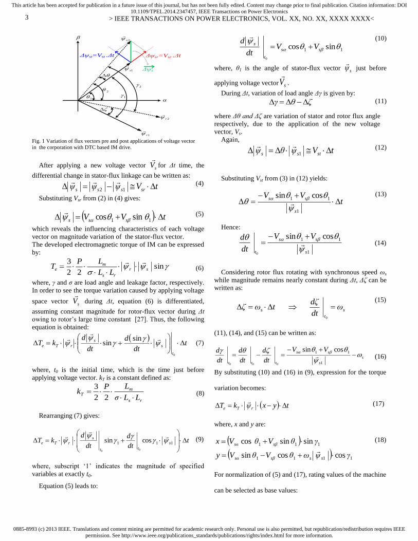
Radial component (Vsr) of the stator-voltage space vector
(sV
) changes the stator-flux magnitude, and the tangential
component (Vst) changes the stator-flux angle as shown in Fig.
1. They can be expressed as:
sincos sssr VVV (2)
cossin ssst VVV (3)
where, θ is the angle of stator-flux vector sψ
.
0885-8993 (c) 2013 IEEE. Translations and content mining are permitted for academic research only. Personal use is also permitted, but republication/redistribution requires IEEEpermission. See http://www.ieee.org/publications_standards/publications/rights/index.html for more information.
This article has been accepted for publication in a future issue of this journal, but has not been fully edited. Content may change prior to final publication. Citation information: DOI10.1109/TPEL.2014.2347457, IEEE Transactions on Power Electronics
> IEEE TRANSACTIONS ON POWER ELECTRONICS, VOL. XX, NO. XX, XXXX XXXX<
3
2
1s
1
2s
2
1
2r
1r
Δψsr=Vsr .Δt Δψst=Vst .Δt
Δψs
Fig. 1 Variation of flux vectors pre and post applications of voltage vector
in the corporation with DTC based IM drive.
After applying a new voltage vector sV
for Δt time, the
differential change in stator-flux linkage can be written as:
tVψψψ srsss 12
(4)
Substituting Vsr from (2) in (4) gives:
tVV sss 11 sincos
(5)
which reveals the influencing characteristics of each voltage
vector on magnitude variation of the stator-flux vector.
The developed electromagnetic torque of IM can be expressed
by:
sin22
3sr
rs
me
LL
LPT
(6)
where, γ and σ are load angle and leakage factor, respectively.
In order to see the torque variation caused by applying voltage
space vector sV
during Δt, equation (6) is differentiated,
assuming constant magnitude for rotor-flux vector during Δt
owing to rotor’s large time constant [27]. Thus, the following
equation is obtained:
t
dt
d
dt
dkT
t
s
s
rTe
0
sinsin
(7)
where, t0 is the initial time, which is the time just before
applying voltage vector. kT is a constant defined as:
rs
mT
LLσ
LPk
22
3
(8)
Rearranging (7) gives:
tdt
d
dt
dkT s
tt
s
rTe
111 cossin
00
(9)
where, subscript ‘1’ indicates the magnitude of specified
variables at exactly t0.
Equation (5) leads to:
11 sincos
0
ss
t
sVV
dt
d
(10)
where, θ1 is the angle of stator-flux vector sψ
just before
applying voltage vector sV
.
During Δt, variation of load angle Δγ is given by:
ζθγ (11)
where Δθ and Δζ are variation of stator and rotor flux angle
respectively, due to the application of the new voltage
vector, Vs.
Again,
tVψθψ stss 1
(12)
Substituting Vst from (3) in (12) yields:
tVV
s
ss
1
11 cossin
(13)
Hence:
1
11 cossin
0 s
ss
t
VV
dt
d
(14)
Considering rotor flux rotating with synchronous speed ωs
while magnitude remains nearly constant during Δt, Δζ can be
written as:
s
t
s ωdt
ζdtωζ
0
(15)
(11), (14), and (15) can be written as:
s
s
ss
ttt
VV
dt
d
dt
d
dt
d
1
11 cossin
000
(16)
By substituting (10) and (16) in (9), expression for the torque
variation becomes:
tyxψkT rTe
(17)
where, x and y are:
1111
111
coscossin
sinsincos
γψωθVθVy
γθVθVx
sssβsα
sβsα
(18)
For normalization of (5) and (17), rating values of the machine
can be selected as base values:

0885-8993 (c) 2013 IEEE. Translations and content mining are permitted for academic research only. Personal use is also permitted, but republication/redistribution requires IEEEpermission. See http://www.ieee.org/publications_standards/publications/rights/index.html for more information.
This article has been accepted for publication in a future issue of this journal, but has not been fully edited. Content may change prior to final publication. Citation information: DOI10.1109/TPEL.2014.2347457, IEEE Transactions on Power Electronics
> IEEE TRANSACTIONS ON POWER ELECTRONICS, VOL. XX, NO. XX, XXXX XXXX<
4
ω
V
ω
VψψωV m
base
basebasemm
(19)
and,
basebasesbaser
rs
mbasee
LL
LPT
sin
22
3,,,
(20)
where, the subscript ‘base’ indicates the base value.
basebase
ss
base
s
pusV
tVV
11 sincos
(21)
Per-unit equation for flux variation results:
11,1, sincos kVV puspuspus
(22)
where, tωk base 1 .
Torque variation can be expressed in per-unit from (6) and
(17) as follows:
tyxT
k
tyxk
T
TT
pupupurpue
basebasesbaserT
rT
basee
epue
,,
,,,
,sin
(23)
where,
base
pussbasepuspuspu
base
base
puspuspu
VVy
VVx
sin
coscossin
sin
sinsincos
111,1,
11,1,
(24)
Equation (23) for torque variation per-unit can be rewritten
as:
1
2
121,
1,1,
1,,
sin2
cossin
sin
kkp
VV
T
pupuspus
puspus
pupuspurpue
(25)
where, 22sin
1
base
k
.
Expression (25) is applicable to any size IM drive, but
because of its dependency on γbase, influencing characteristics
of voltage vectors can differ in low and high power
applications.
III. FUNDAMENTALS OF MATRIX CONVERTER BASED DTC
SCHEME
The direct matrix converter as shown in Fig. 2(a) is of the
highest practical interest as it connects a three-phase voltage
source with a three-phase load (typically a motor). There are
27 possible switching configurations, but only 21 of them are
useful in DTC algorithm, which are given in Table 1. Fig. 2(b)
shows the first 18 active voltage vectors having fixed
directions. As shown in Table 1, the magnitudes of voltage
vectors depend on the input voltages. The fourth and fifth
columns of Table 1 show real (α) and imaginary (β)
components of the matrix converter’s output voltage vectors in
stationary reference frame. The last three switching
configurations correspond to zero-output voltage vectors.
Based on the earlier torque and flux equations, the block
diagram of the proposed matrix converter based DTC scheme
for IM drive is shown in Fig. 3.
SaA SbA ScA SaB SbB ScB SbCSaC ScC
IM
Cf
Lf
LC Filter
Matrix Converter
Induction Motor
VA VB VCGrid
LfLf
Cf
Cf
(a)
0ov
3,2,1
6,5,4
9,8,7
1
23
4
5
6
torsec
(b)
Fig. 2. Matrix converter. (a) direct matrix converter configuration. (b)
active voltage vectors produced by matrix converter
IV. EFFECT OF VOLTAGE VECTOR ON FLUX AND TORQUE
A. Effect of voltage-vector on flux
The IM parameters used for simulation are shown in Table
2. For flux variation in different voltage vectors, α and β
components of each vector were substituted based on per-unit,
and equations obtained. e.g., voltage vector of first order in
(+)ve region is obtained from:
)0sin(.)0cos(.3
20
3
21 jvvvv BAAB
(26
)
Equation (26) converted into per-unit based on machine’s
rated voltage (Vbase); α and β components of v+1 yields:
0
)6
cos(3
2
,1
1,1
pu
m
pu
v
tV
vv
(27)

0885-8993 (c) 2013 IEEE. Translations and content mining are permitted for academic research only. Personal use is also permitted, but republication/redistribution requires IEEEpermission. See http://www.ieee.org/publications_standards/publications/rights/index.html for more information.
This article has been accepted for publication in a future issue of this journal, but has not been fully edited. Content may change prior to final publication. Citation information: DOI10.1109/TPEL.2014.2347457, IEEE Transactions on Power Electronics
> IEEE TRANSACTIONS ON POWER ELECTRONICS, VOL. XX, NO. XX, XXXX XXXX<
5
Table 1 3×3 matrix converter switching configuration
switching combinations on switches
voltage-vector
values component valueα β component value
vo αo
+1 SAa SBb SBc 0 0
-1 SBa SAb SAc 0 0
+2 SBa SCb SCc 0 0
-2 SCa SBb SBc 0 0
+3 SCa SAb SAc 0 0
-3 SAa SCb SCc 0 0
+4 SBa SAb SBc
-4 SAa SBb SAc
+5 SCa SBb SCc
-5 SBa SCa SBc
+6 SAa SCb SAc
-6 SCa SAb SCc
+7 SBa SBb SAc
-7 SAa SAb SBc
+8 SCa SCb SBc
-8 SBa SBb SCc
+9 SAa SAb SCc
-9 SCa SCb SAc
0A SAa SAb SAc 0 … 0 0
0B SBa SBb SBc 0 … 0 0
0C SCa SCb SCc 0 … 0 0
From (22) and (27) the flux variation can be obtained as:
6
11, 10120).((cos)6.(cos(3
2||
tpus
(28)
In (28), rated frequency of motor is considered as 50Hz,
and sampling time-interval is considered 1µs. The comparison
of stator flux variation between the conventional (60° sector)
and the proposed (30° sector) switching schemes is shown in
Figs. 4 and 5, respectively. It is seen from Figs. 4(a) and 5(a)
that the peak-to-peak flux variation in both conventional and
proposed switching scheme is the same. However, there is 180°
phase difference between Figs. 4(a) and 5(a) by applying
voltage vectors v+1 and v-1, respectively. In Fig. 4(b) the colour
area indicates the (+)ve ( 0|| pus ) variation and white
area indicates the (-)ve b( 0|| pus ) variation of stator
flux. Note that in some sectors, applying the voltage vector
when the space vector is divided into six 60° sectors is
impossible because the flux increases and decreases at the
same time in the sectors. For example, (when ωt < 120° and
60° < θ < 120°), flux in one half of this sector is positive
which means that v+1 increases the stator flux while in the other
half it is negative which means that v+1 decreases the stator
flux. So, the use of v+1 in this sector is not allowed. Hence, for
the conventional switching scheme the degree of freedom to
choose the stator-voltage vector is limited. Fig. 5(b) shows flux
vector variations of voltage vector v+1 for the proposed 30°
sector based switching scheme. It is clearly seen from the
figures that there is no sector when the flux is increasing and
decreasing simultaneously. Thus, the stator-voltage vector can
be applied for each sector for the proposed 30° sector scheme.
Therefore the degrees of freedom to choose the stator-voltage
vector with the proposed 30° sector switching scheme is
increased significantly as compared the conventional 60° sector
scheme. For stator-voltage vector v-1, the stator flux variation is
exactly opposite to that of voltage vector v+1. This statement is
true for all stator-voltage vectors (e.g., v+5 and v-5, etc.)
ABv32 )6cos(32 tVm
ABv32 )6cos(32 tVm
BCv32 )2cos(32 tVm
BCv32 )2cos(32 tVm
CAv32 )65cos(32 tVm
CAv32 )65cos(32 tVm
ABv32 32 )6cos(31 tVm)6cos( tVm
ABv32 32 )6cos(31 tVm)6cos( tVm
BCv32 32 )2cos(31 tVm)2cos( tVm
BCv32 32 )2cos(31 tVm)2cos( tVm
CAv32 32 )65cos(31 tVm)65cos( tVm
CAv32 32 )65cos(31 tVm)65cos( tVm
ABv32 34 )6cos(31 tVm)6cos( tVm
ABv32 34 )6cos(31 tVm)6cos( tVm
BCv32 34 )2cos(31 tVm)2cos( tVm
BCv32 34 )2cos(31 tVm)2cos( tVm
CAv32 34 )65cos(31 tVm)65cos( tVm
CAv32 34 )65cos(31 tVm)65cos( tVm

0885-8993 (c) 2013 IEEE. Translations and content mining are permitted for academic research only. Personal use is also permitted, but republication/redistribution requires IEEEpermission. See http://www.ieee.org/publications_standards/publications/rights/index.html for more information.
This article has been accepted for publication in a future issue of this journal, but has not been fully edited. Content may change prior to final publication. Citation information: DOI10.1109/TPEL.2014.2347457, IEEE Transactions on Power Electronics
> IEEE TRANSACTIONS ON POWER ELECTRONICS, VOL. XX, NO. XX, XXXX XXXX<
6
IM
*
eT
Te
< sin Φ i >
ψ*
s
sψs
HTe
Hψ
HΦ
+
_
+
_
switching
states
matrix
converter switching
states
MUX
MUX
3-phase
AC input
(power grid)ie
_
1
234
5
6
7
89 10
1112
ψ
1
234
56
7
89 10
11
12
switching
configuration
selection
controlling (DTC)
MC switching power electronic
measurement
estimation section
torque and flux
estimator
< sin Φ i >
estimator
sψ
Te
< sin Φ i >oe
_
ie_
i_
i
_
io
inout
inout
Fig. 3 Block diagram of the proposed DTC based switching strategy by matrix converter.
060
120180
240300
360
060
120180
240300
360
-5
5
0
× 10-4
input-voltage vector angle,
ωt (in degrees)
stator- flux vector angle,
θ1 (in degrees)
stat
or-
flu
x v
aria
tio
ns,
ΔΨ
s (W
b)
4.4×10⁻⁴
-4.4×10⁻⁴
0
360
300
240
180
0360300240180120600
stat
or-
flu
x v
ecto
r an
gle
, θ
1 (
in
deg
rees
)
input-voltage vector angle, ωt (in
degrees)
60
120
N
U
N
U
N
U
N
U
N
U
N
U
N
U
N
U
N
U
N
U
N
U
N
U
(a) (b) Fig. 4 Stator-flux vector variation of conventional (60° sector) DTC scheme under the rated condition of the motor for v+1 (NU=No Use). (a)
stator flux variation. (b) stator-flux vector behavior characteristic
0
60
120
180
240
300
360
060
120180
240300
360
-5
5
0
× 10-4
input-voltage vector angle,
ωt (in degrees)
stator- flux vector angle,
θ1 (in degrees)
stat
or-
flux v
aria
tions,
ΔΨ
s (W
b)
4.4×10⁻⁴
-4.4×10⁻⁴
0
3090
150210
270330
30
90
150
210
270
330
360
330
300
270
240
210
180
150
120
90
60
30
03603303002702402101801501209060300
stat
or-
flux v
ecto
r an
gle
, θ
1 (
in d
egre
es)
input-voltage vector angle, ωt (in degrees)
(a) (b)
Fig. 5 Stator-flux vector variation of the proposed (30° sector) DTC
scheme under rated condition of the motor for v-1. (a) stator flux variation.
(b) stator-flux vector behavior characteristic
Fig. 6 compares instantaneous basic voltage vectors of the
proposed (30°- sector) method with the conventional (60°-
sector) method. As it is evident in Fig. 6, the magnitude of
voltage vector for the proposed scheme is always higher than
or at least equal to that of conventional scheme. Thus, the
voltage ripple could reduce with the proposed scheme.
Moreover, the probability of stator voltage reference
transgress during large torque demand may reduce because the
voltage reference vector limitations are enclosed by 12-side
polygonal rather than hexagonal boundary. According to Fig.6
the maximum value of reference voltage vector for 12-side
polygonal space vector is )cos(2 rVsm , and the
maximum value of reference voltage vector for hexagonal
boundary is )2
cos(1
rVsm . While
6 , the maximum
value of reference voltage vector for 12-side polygonal space
vector is )(11.1 12 smsm VV
B. Effect of voltage-vector on torque
Torque variation by applying vectors v+1 and v+2 are shown in
Figs. 7 (a) and 7 (c), respectively, for the proposed switching
scheme. It is clearly seen from these figures that the torque
variation not defected when the voltage vector switches from
v+1 to v+2. The corresponding torque variations on θ1-ωt plane
are shown in Figs. 7(b) and 7(d), respectively. In Figs 7(b) and
7(d) two colour pericyles indicate the (+)ve torque variation
and the white area indicates the (-)ve torque variation. The
area of colour regions is the same in both Figs. 7 (b) and 7 (d)
except their positions are changed. In other words, with the
application of various voltage vectors, there is no additional
torque variation. It means that with applying a different
voltage vector, the torque ripple remains constant. .
60°
Vsm1
Vsm2
(100)
(110)(010)
(011)
(001) (101)
Vsm1:minimum voltage vector for
conventional scheme (60°)
Vsm2: minimum voltage vector for
proposed scheme (30°)
Vsm1
Vsm2
(100)
(110)(010)
(011)
(001) (101)
Vsm1:minimum voltage vector
for conventional scheme (60°)
Vsm2: minimum voltage
vector for proposed
scheme (30°)
Zoom-in view
. Fig. 6 Instantaneous basic voltage vectors for both conventional (60°
sector) and proposed (30° sector) switching scheme, and the zoom-in view of
the first sector.
Table 2 Specifications and parameters of the 3-phase test induction-
motor, referred to the stator side.
rated power S 1100 VA
rated torque Te, base 6.3 Nm
rated voltage Vl-l 380 V
number of poles 2P 2
rated frequency f 50 Hz
stator resistance Rs 1.405 Ω
stator reactance Xls 1.834 Ω
mutual reactance Xm 54.09 Ω
rotor resistance R'r 1.395 Ω
rotor reactance X'lr 1.834 Ω
friction factor J 0.0131 kg/m2

0885-8993 (c) 2013 IEEE. Translations and content mining are permitted for academic research only. Personal use is also permitted, but republication/redistribution requires IEEEpermission. See http://www.ieee.org/publications_standards/publications/rights/index.html for more information.
This article has been accepted for publication in a future issue of this journal, but has not been fully edited. Content may change prior to final publication. Citation information: DOI10.1109/TPEL.2014.2347457, IEEE Transactions on Power Electronics
> IEEE TRANSACTIONS ON POWER ELECTRONICS, VOL. XX, NO. XX, XXXX XXXX<
7
(a) (b)
360
330
300
270
240
210
180
150
120
90
60
30
03603303002702402101801501209060300
stat
or-
flu
x v
ecto
r an
gle
, θ
1 (
in d
egre
es)
input-voltage vector angle, ωt (in degrees) (c) (d)
Fig. 7 Torque variation for the proposed (30° sector) DTC based IM drive under the rated condition of the motor. (a) torque variation for voltage vector v+1 .
(b) torque behavior characteristic for v+1 .(c) torque variation for voltage vector v+2. (d) torque behavior characteristic for v+2.
It is found that the developed torque of the motor is stable at
different load and speed conditions. Additionally, it is clearly
seen from these figures that the torque for v+1 and v+2 have
same space-dependent expression, and for time-dependent
expression. The torque variation by applying vectors v+2 lags
the torque variation as a result of applying v+1 by π/3.
V. VECTORS SUITABLE FOR CONTROL
To examine the effect of 18 active voltage vectors produced
by the matrix converter on the flux and torque, a procedure
similar to that applied for v+1 is applied. Voltage vectors with
stable characteristic in the 30° sectors are then chosen as
suitable for control of motor torque and flux. Based on the
earlier result analysis, the proposed switching technique is
extracted, and shown in Table 3. Hφ and HTe are the outputs of
flux and torque hysteresis controllers, respectively, as shown
below:
1,
1,
*
*
e
e
Tee
Tee
HTT
HTT
(29)
1,
1,
*
*
φ
φ
Hφφ
Hφφ
(30)
Table 3 is produced for the stator flux in the first and the
second sectors, but owing to symmetry conditions in space
vector the results are valid also for the remaining sectors. It is
to be noted that Hφ=+1 indicate the flux needs to increase and
Hφ=-1 indicate the flux needs to decrease. Similarly HTe= +1
indicate that the torque needs to increase and HTe= -1 indicate
that the torque needs to decrease.
Table 3 lists the results for the first 6 sectors of the input
voltage. The results for the 6 remaining sectors contrast, those
of the first 6 sectors, e.g., in 7th sector (L=7) the voltage
vector is -9 while, the voltage vector is +9 in the first voltage
sector (L=1) and this logic is true for all remaining sectors
(L=7,8,9,…,12).
Table 4 shows the switching scheme codes corresponding to
each voltage vector.
VI. SELECTION OF OPTIMUM VECTORS TO MINIMIZE THE
SWITCHING LOSSES
As can be seen from Table 3, there are multiple vectors for
switching selection in some sectors which increases the
degrees of freedom in selection of space-vector voltage for
DTC of IM by matrix converter.
The enhanced degrees of freedom improve the IM drive
performance. In addition, the proposed 12-sector switching
method is independent of the load and speed variation, in the
expense of introducing of no use sectors which are included
in Table 3 when k is equal to an even number, Hφ=-1 and
HTe=+1. These redundancies of vectors for switching selection
provide an additional option, to optimize the switching losses
by proposed 12-sector method compares to the conventional
switching. While the switching is fixed in conventional
method and there is no redundancy of vectors for switching
selection, the proposed method can provide the optimum
switching losses due to exist of multiple vectors for switching
selection. In order to obtain minimum switching frequency
which provides optimum switching loss, the space-vector
voltage with lowest flux variation is selected from Table 3 as
the best switching vector. This selection increases the
switching period by extending time to reach the hysteresis
band in both flux and torque. Accordingly, the switching
frequency is optimized hence the switching losses are
diminished.
0
60
120
180
240
300
360
060
120180
240300
360
-6
4
0
× 10-3
stator-flux vector angle,
θ1 (in degrees)
3.5×10⁻³
-5.2×10⁻³
0
3090
150210
270330
30
90
150
210
270
330
torq
ue
var
iati
on
s, Δ
Te
(Nm
)
input-voltage vector angle,
ωt (in degrees)
360
330
300
270
240
210
180
150
120
90
60
30
03603303002702402101801501209060300
stat
or-
flu
x v
ecto
r an
gle
, θ
1 (
in d
egre
es)
input-voltage vector angle, ωt (in degrees)
0
60
120
180
240
300
360
060
120180
240300
360
-6
4
0
× 10-3
stator-flux vector angle,
θ1 (in degrees)
3.5×10⁻³
-5.2×10⁻³
0
3090
150210
270330
30
90
150
210
270
330
torq
ue
var
iati
on
s, Δ
Te
(Nm
)
input-voltage vector angle,
ωt (in degrees)

0885-8993 (c) 2013 IEEE. Translations and content mining are permitted for academic research only. Personal use is also permitted, but republication/redistribution requires IEEEpermission. See http://www.ieee.org/publications_standards/publications/rights/index.html for more information.
This article has been accepted for publication in a future issue of this journal, but has not been fully edited. Content may change prior to final publication. Citation information: DOI10.1109/TPEL.2014.2347457, IEEE Transactions on Power Electronics
> IEEE TRANSACTIONS ON POWER ELECTRONICS, VOL. XX, NO. XX, XXXX XXXX<
8
Table 3 Degrees of freedom in selecting appropriate voltage vector for the proposed DTC scheme.
proper vectors for k as an odd number (k = 1,3,5,7,9,11)
Hφ +1 -1
HTe +1 -1 +1 -1
L=1 (3k+9)/2 (3k-1)/2 , (3k+1)/2 , (3k+33)/2 , (3k+3)/2 , (3k+29)/2 ,
(3k+31)/2 (3k+15)/2 (3k+23)/2 , (3k+25)/2 , (3k+19)/2 , (3k+27)/2
L=2 (3k+9)/2 (3k-1)/2 , (3k+1)/2 , (3k+33)/2 , (3k+3)/2 , (3k+29)/2 ,
(3k+31)/2 (3k+15)/2 (3k+23)/2 , (3k+25)/2 , (3k+17)/2 , (3k+27)/2
L=3 (3k+7)/2 (3k+1)/2 , (3k+11)/2 , (3k+33)/2 , (3k+17)/2 , (3k+3)/2
, (3k+31)/2 (3k+13)/2 (3k-1)/2 , (3k+25)/2 , (3k+5)/2 , (3k+27)/2
L=4 (3k+7)/2 (3k+1)/2 , (3k+11)/2 , (3k+33)/2 , (3k+17)/2 , (3k+3)/2
, (3k+31)/2 (3k+13)/2 (3k+21)/2 , (3k+25)/2 , (3k+5)/2 , (3k+27)/2
L=5 (3k+23)/2 (3k+1)/2 , (3k+21)/2 , (3k+11)/2 , (3k+17)/2 ,
(3k+31)/2 , (3k+15)/2 (3k+29)/2 (3k+25)/2 , (3k+9)/2 , (3k+3)/2 , (3k+5)/2
L=6 (3k+23)/2 (3k+1)/2 , (3k+21)/2 , (3k+11)/2 , (3k+17)/2 ,
(3k+31)/2 , (3k+15)/2 (3k+29)/2 (3k+25)/2 , (3k+9)/2 , (3k+19)/2 , (3k+5)/2
proper vectors for k as an even number (k = 2,4,6,8,10,12)
Hφ +1 -1
HTe +1 -1 +1 -1
L=1 (3k+8)/2
(3k+12)/2 (3k-4)/2 , (3k-2)/2 , 3k/2 -
(3k+2)/2 , (3k+20)/2 , (3k+22)/2 , (3k+26)/2 ,
(3k+28)/2 , (3k+24)/2
L=2 (3k+10)/2
(3k+12)/2 (3k-4)/2 , (3k-2)/2 , 3k/2 -
(3k+2)/2 , (3k+20)/2 , (3k+22)/2 , (3k+26)/2 ,
(3k+28)/2 , (3k+24)/2
L=3 (3k+10)/2
(3k+12)/2 (3k-2)/2 , (3k+14)/2 , 3k/2 -
(3k+8)/2 , (3k+30)/2 , (3k+22)/2 , (3k+28)/2 , (3k+2)/2
, (3k+24)/2
L=4 (3k+10)/2
(3k+26)/2 (3k-2)/2 , (3k+14)/2 , 3k/2 -
(3k+8)/2 , (3k+30)/2 (3k+22)/2 , (3k+28)/2 , (3k+2)/2 ,
(3k+24)/2
L=5 (3k+10)/2
(3k+26)/2 (3k-2)/2 , (3k+18)/2 , (3k+14)/2 -
(3k+8)/2 , (3k+22)/2 , (3k+6)/2 , (3k+28)/2 , (3k+12)/2
, (3k+2)/2
L=6 (3k+30)/2
(3k+26)/2 (3k-2)/2 , (3k+18)/2 , (3k+14)/2 -
(3k+8)/2 , (3k+22)/2 , (3k+6)/2 , (3k+28)/2 , (3k+12)/2
, (3k+2)/2
The lowest average values in each sector of the contour-
map are chosen for switching by comparing the variation rates
of the flux correspond to each input voltage in different flux
sectors.
VII. SIMULATION RESULT OF THE PROPOSED DTC BASED IM
DRIVE
The proposed DTC based IM drive is simulated extensively
at different operating conditions using Matlab/Simulink
software. The sample results are presented below.
Figs. 8 compares the starting responses of the DTC based
IM drive at rated speed under full load and 20% of load
conditions for the proposed (30°-sector) and conventional
(60°-sector) switching scheme, respectively. Fig. 8(a) depicts
how actual speed follows the reference speed. It is seen from
Figs. 8(b) and 8(c) that the torque ripple is less for the
proposed switching scheme as compared to the conventional
switching under full load terms and also in Figs. 8(d) and 8(e)
the comparison has been applied between suggested and
conventional methods for 20% of loading conditions. Thus,
the proposed switching scheme introduces lower vibration to
the motor. As the input current of the matrix converter is an
important variable that should be monitored, the waveform of
input current and its harmonic spectrum in the steady-state
operation of the motor for both proposed and conventional
methods at rated loadare shown in Figs. 8(f) and 8(g),
respectively and then for 20% of rated load illustrated in Fig.
8(h) and 8(i). The components of the input filter are
inductance (Lr=4mH) and capacitor (Cr=40µF). It can be seen
that the distortion of input current for the conventional method
is more severe than that of the proposed method. The THDs of
the conventional and proposed methods under full load
condition are 8.56% and 5.15%, respectively as well as one
fifth of rated load are similarly 24.19% and 40.27%.
Fig. 9 shows the responses of the proposed DTC based IM
drive at step changes of load conditions. It is seen from Fig.
9(a) that the motor can follow the command speed in spite of
changes of the load from no-load to full-load conditions. Thus,
the proposed drive is insensitive to load variations. It is also
seen from Fig. 9(b) that the torque ripple is very low at
different load conditions. It is found that the flux remains
constant while the load changes and the stator current changes
with load, accordingly. Figs. 9(c) and (d) show the produced
flux and stator currents, respectively.
It is found that the motor can follow the command speed
even if it changes to the reverse direction. Therefore, the
performance of the proposed switching based matrix converter
for IM drive is found robust at different operating conditions.
Fig. 10 shows the speed, produced electromagnetic torque,
flux and stator currents, respectively.

0885-8993 (c) 2013 IEEE. Translations and content mining are permitted for academic research only. Personal use is also permitted, but republication/redistribution requires IEEEpermission. See http://www.ieee.org/publications_standards/publications/rights/index.html for more information.
This article has been accepted for publication in a future issue of this journal, but has not been fully edited. Content may change prior to final publication. Citation information: DOI10.1109/TPEL.2014.2347457, IEEE Transactions on Power Electronics
> IEEE TRANSACTIONS ON POWER ELECTRONICS, VOL. XX, NO. XX, XXXX XXXX<
9
0.2 0.6 0.8 1.2 1.40 1.6
actual speed
reference speed
spee
d (
rpm
)
1473
1500
1350
1200
1050
900
750
600
450
300
150
0
0.4 1
time (s)
0.2 0.6 0.8 1.2 1.4 1.60.4 10
17.5
6.3
7.7
9.1
10.5
11.9
13.3
14.7
16.1
18.9
6.1
6.5
zoom-in view
4.9
time (s)
elec
trom
agnet
ic t
orq
ue
Te
(Nm
)
0.2 0.6 0.8 1.2 1.4 1.60.4 10
17.5
6.3
elec
trom
agnet
ic t
orq
ue
Te
(Nm
)
7.7
9.1
10.5
11.9
13.3
14.7
16.1
18.9
5.8
6.8
zoom-in view
4.9
time (s)
0.2 0.6 0.8 1.2 1.4 1.60.4 10
18
2
elec
trom
agnet
ic t
orq
ue
Te
(Nm
)
4
6
8
10
12
14
16
20
1.04
1.5
zoom-in view
0
time (s)
0.2 0.6 0.8 1.2 1.4 1.60.4 10
18
2
4
6
8
10
12
14
16
20
0.69
1.82
zoom-in view
0
time (s)
elec
trom
agnet
ic t
orq
ue
Te
(Nm
)
3.6
1.6
0200 400 600 800 1000 12000
Mag
(%
of
fundam
enta
l)
frequency (Hz)
fundamental (50Hz) = 2.347 , THD= 5.15%
2.4
0.8
3.2
0
1
2
3
-1
-2
-31 1.21.02 1.04 1.06 1.08 1.1 1.12 1.14 1.16 1.18
input
curr
ent
(Am
p)
t (sec)
ia
(c)(b)(a)
(d) (e) (f)
0
1
2
3
-1
-2
-31 1.21.02 1.04 1.06 1.08 1.1 1.12 1.14 1.16 1.18
input
curr
ent
(Am
p)
t (sec)
ia
5
3
4
2
1
0
200 400 600 800 1000 12000
Mag
(%
of
fundam
enta
l)
frequency (Hz)
fundamental (50Hz ) = 2. 339 , THD= 8.56%
6
7
0
0.5
0.75
-0.25
-0.5
-0.751 1.21.02 1.04 1.06 1.08 1.1 1.12 1.14 1.16 1.18
input
curr
ent
(Am
p)
t (sec)
ia0.25
fundamental (50Hz) = 0.491 , THD= 24.19%
7
3
6
2
1
0200 400 600 800 1000 12000
Mag
(%
of
fundam
enta
l)
frequency (Hz)
8
9
5
4
0
0.5
0.75
-0.25
-0.5
-0.75
1 1.21.02 1.04 1.06 1.08 1.1 1.12 1.14 1.16 1.18
input
curr
ent
(Am
p)
t (sec)
ia0.25
fundamental (50Hz) = 0.488 , THD= 40.27%
12
4
10
2
0
200 400 600 800 1000 12000
Mag
(%
of
fundam
enta
l)
frequency (Hz)
14
16
8
6
(g) (h) (i) Fig. 8 Responses comparison of the proposed switching method with conventional switching method at rated speed (1473 rpm),rated load (6.3 Nm), and 20% of
rated load.(a) speed. (b) torque response of the proposed method under rated load. (c) torque response of the conventional method under rated load. (d) torque response of the proposed method under 20% of rated load. (e) torque response of the conventional method under 20% of rated load. (f) input current and its THD
spectrum of the proposed method under rated load.(g) input current and its THD spectrum of the conventional method under rated load. (h) input current and its
THD spectrum of the proposed method under 20% of rated load. (i) input current and its THD spectrum of the conventional method under 20% of rated load
actual speed
reference speed
spee
d (
rpm
)
14731500
1350
1200
1050
900
750
600
450
300
150
00.5 210.25 0.75 1.25 1.5 1.750
time (s)
(a)
0.5 210.25 0.75 1.25 1.5 1.750
0
2
4
6
8
10
12
14
16
18
-2
Te
(Nm
)
time (s)
flux,
Ψ (
Wb
)
2.4
2.3
2.25
2.35
2.2
2.1
2.05
2.45
2.5
2.55
2.6
0.5 210.25 0.75 1.25 1.5 1.750
time (s)
6
-4
02
-2
0.5 210.25 0.75 1.25 1.5 1.750
isa
isb
isc
-6
4
stat
or
curr
ent
(Am
p)
6
-4
02
-2
-6
4
6
-4
02
-2
-6
4
time (s)
(b) (c)
(d) Fig. 9 Responses of the proposed DTC based IM drive for step changes of load condition. (a) speed. (b) electromagnetic torque. (c) stator flux. (d) stator-phase currents.

0885-8993 (c) 2013 IEEE. Translations and content mining are permitted for academic research only. Personal use is also permitted, but republication/redistribution requires IEEEpermission. See http://www.ieee.org/publications_standards/publications/rights/index.html for more information.
This article has been accepted for publication in a future issue of this journal, but has not been fully edited. Content may change prior to final publication. Citation information: DOI10.1109/TPEL.2014.2347457, IEEE Transactions on Power Electronics
> IEEE TRANSACTIONS ON POWER ELECTRONICS, VOL. XX, NO. XX, XXXX XXXX<
10
-1473
900
actual speed
reference speed
time (s)
1000
500
-1000
-500
0
0.5 1 1.5 2 2.50
6.3
16.8
Te
(Nm
)
-16.8
0
time (s)
flux, Ψ
(W
b)
2.4
2.3
0.5 1 1.5 2 2.50
2.2
2.1
2
1.9
1.8
1.7
1.6
2.5
2.6
time (s)
6
-6
0
stat
or
curr
ent
(Am
p)
2
-2
0.5 1 1.5 2 2.50
4
-4
6
-6
0
2
-2
4
-4
6
-6
0
2
-2
4
-4
isa
isb
isc
time (s)
(a) (b) (c)
(d)
0
1.05 1.015 1.02 1.03 1.035 1.041.01 1.0251
100
200
300
400
500
-100
-200
-300
-400
-500
outp
ut
volt
age,
VA
B (
v)
3000 9000 150000
fundamental (50Hz) = 379.9 , THD = 61.9%
time (s)
6000 12000
15
20
5
0
10
(e)
0
1.05 1.015 1.02 1.03 1.035 1.041.01 1.0251
100
200
300
400
500
-100
-200
-300
-400
-500
outp
ut
volt
age,
VA
B (
v)
3000 9000 150000
fundamental (50Hz) = 380.4 , THD = 58.1%
6000 12000
15
20
5
0
10
time (s)
(f)
0.5 1 1.5 2 2.50
1473
spee
d (
rpm
)
Mag
(%
of
fundam
enta
l)
Mag
(%
of
fundam
enta
l)
frequency (Hz) frequency (Hz)
Fig. 10 Responses of the proposed DTC based IM drive for step changes of command speed. (a) speed. (b) electromagnetic torque. (c) stator flux. (d) stator-
phase currents. (e) output voltage and its THD spectrum of the proposed method. (f) output voltage and its THD spectrum of the conventional method
Table 4 Matrix converter switching status for proposed
switching scheme.
It is clear that the motor can reverse rotation direction
smoothly without any overshoot/undershoot or steady state
error. In addition, the waveform of output voltage and its
harmonic spectrum in the steady-state operation of the motor
for both proposed and conventional methods are shown in
Figs. 10(e) and 10(f), respectively. It can be seen that the
harmonics of the proposed method are mainly in the vicinity
of the switching frequency (10 kHz) as shown in Fig. 10(e),
while the harmonics of the conventional method are mainly
distributed within the range of 0.5–6 kHz as shown in Fig.
10(f). The result shows that the output voltage THDs of the
conventional and proposed methods are 58.1% and 61.9%,
respectively. To evaluate performance of the proposed method
precisely and entirely, the comparison of the proposed method
and the conventional switching method is summarized and
tabulated in Table 5.
Table 5 Comparison of proposed switching method and
conventional method
parameters of
comparison
proposed
method
conventional
method[3]
THD of MC input
current 5.15% 8.56%
THD of MC output voltage
61.9%
harmonics are mainly in the
vicinity of the
switching frequency (10
kHz)
58.1%,
harmonics are mainly distributed within the
range of
(0.5–6 kHz)
torque ripple reduction 60% reduction fixed
maximum limit of
reference voltage within
circular locus of space vectors without over
modulation
1.111smV 1smV
degrees of freedom to select appropriate
voltage vectors for DTC
intensified fixed
swit
chin
g
cod
e
vec
tor
nu
mb
er
on
sw
itch
es
equ
ivale
nt
vec
tor
cod
e
in o
dd
sect
ors
equ
ivale
nt
vec
tor
cod
e
in e
ven
sect
ors
1 v+1 SAa SBb SCb (3k-1)/2 (3k-4)/2
2 v+2 S Ab SBc SCc (3k+1)/2 (3k-2)/2
3 v-3 S Aa SBc SCc (3k+3)/2 3k/2
4 v-7 S Aa SBa SCb (3k+5)/2 (3k+2)/2
5 v-8 S Ab SBb SCc (3k+7)/2 (3k+4)/2
6 v+9 S Aa SBa SCc (3k+9)/2 (3k+6)/2
7 v+4 S Ab SBa SCb (3k+11)/2 (3k+8)/2
8 v+5 S Ab SBb SCc (3k+13)/2 (3k+10)/2
9 v-6 S Ab SBa SCc (3k+15)/2 (3k+12)/2
10 v-1 S Ab SBa SCa (3k+17)/2 (3k+14)/2
11 v-2 S Ac SBb SCb (3k+19)/2 (3k+16)/2
12 v+3 S Ab SBa SCa (3k+21)/2 (3k+18)/2
13 v+7 S Ab SBb SCa (3k+23)/2 (3k+20)/2
14 v+8 S Ab SBc SCb (3k+25)/2 (3k+22)/2
15 v-9 S Ab SBc SCa (3k+27)/2 (3k+24)/2
16 v-4 S Aa SBb SCa (3k+29)/2 (3k+26)/2
17 v-5 S Ab SBc SCb (3k+31)/2 (3k+28)/2
18 v+6 S Aa SBc SCa (3k+33)/2 (3k+30)/2
19 0a S Aa SBa SCa 19 19
20 0b S Ab SBb SCb 20 20
21 0c S Ac SBc SCc 21 21

0885-8993 (c) 2013 IEEE. Translations and content mining are permitted for academic research only. Personal use is also permitted, but republication/redistribution requires IEEEpermission. See http://www.ieee.org/publications_standards/publications/rights/index.html for more information.
This article has been accepted for publication in a future issue of this journal, but has not been fully edited. Content may change prior to final publication. Citation information: DOI10.1109/TPEL.2014.2347457, IEEE Transactions on Power Electronics
> IEEE TRANSACTIONS ON POWER ELECTRONICS, VOL. XX, NO. XX, XXXX XXXX<
11
VIII. EXPERIMENTAL RESULTS
To verify the feasibility and effectiveness of the proposed
DTC scheme based on 12-side polygonal space vector of
voltage and flux, a matrix converter connected to 3-phase
network through a variable AC power supply to feed a 1kw 3-
phase IM was implemented. The experimental setup is shown
in Fig. 11 while the motor parameters are same as the
parameters for simulation and listed in Table 2. In order to
attenuate the harmonics of switching, an LC input filter was
designed based on the values extracted from simulation. The
matrix converter bidirectional switching is configured using
IGBTs as in Fig. 1. The proposed control algorithm is
implemented by using TMS320F28335 digital signal
processor (DSP).
3 phase
AC source
input filter
Vab Iia
feedback
setup
T ωm
matrix
converter
gate drive
DSP
TMS320F28335
Fig. 11 photograph of experimental setup
A. Steady-State performance
Fig. 12 presents the steady-state performance of the
proposed switching scheme under rated conditions of the
motor, speed (1473 rpm) and load (6.3 Nm). The there-phase
waveform of the output voltage and stator current are shown
in Figs. 12(a) and 12(b), respectively. Fig. 12(c) shows the
three-phase input currents of the matrix converter at the steady
- state performance under rated conditions of IM. The
electromagnetic torque and speed waveforms of induction
motor at rated condition are shown in Figs. 12(d) and 12(e),
respectively. As it is evident in the zoom-in view, the ripples
for both speed and electromagnetic torque are rather
acceptable despite of high-frequency ripples.
B. Dynamic performance
Fig. 13 shows the waveforms of the speed, electromagnetic
torque and stator current of the IM drove by proposed method
with speed reference value stepping up from 500 rpm to 1000
rpm at full-load condition (6.3 Nm). It is evident that with the
step change of speed reference value the electromagnetic
torque steps up within a short period. Once the actual speed
reaches to the reference value, the electromagnetic torque
reaches to the nominate value for a short period of time. It is
concluded that the proposed method has the advantage of fast
torque, dynamic response with acceptable ripples.
Fig.14 shows the waveforms of the speed, electromagnetic
torque and stator current of the IM drove by proposed method
with load torque step up from no-load to full-load, while the
reference speed is kept constant at rated speed of 1475 rpm.
The experimental results show that with the abrupt change of
load, the electromagnetic torque increases rapidly and the
speed reaches to the reference value only after a short period
of time.
(a)
vL
L
[400 V
/div
]
vAB
vBC
vCA
time [5 ms/div]
i s
[4 A
/div
]
isa
isb
isc
time [10 ms/div]
(b)
ii
[4 A
/div
]
time [10 ms/div]
ia ib ic
(c)
Te
[5 N
m/d
iv]
time [100 ms/div]
zoom-in view
Te
[1 N
m/d
iv]
time [20 ms/div]
(d)
sp
eed
[ 500 r
pm
/div
]
time [200 ms/div]
zoom-in view
sp
eed
[ 50 r
pm
/div
]
time [5 ms/div]
(e) Fig. 12 experimental waveforms of steady-state performance of proposed
method at rated speed (1473 rpm) and rated load (6.3 Nm). (a) output voltage.
(b) stator current. (c) input current. (d) electromagnetic torque. (e) speed

0885-8993 (c) 2013 IEEE. Translations and content mining are permitted for academic research only. Personal use is also permitted, but republication/redistribution requires IEEEpermission. See http://www.ieee.org/publications_standards/publications/rights/index.html for more information.
This article has been accepted for publication in a future issue of this journal, but has not been fully edited. Content may change prior to final publication. Citation information: DOI10.1109/TPEL.2014.2347457, IEEE Transactions on Power Electronics
> IEEE TRANSACTIONS ON POWER ELECTRONICS, VOL. XX, NO. XX, XXXX XXXX<
12
spee
d
[ 5
00
rp
m/d
iv]
time [50 ms/div](a)
Te
[5 N
m/d
iv]
time [50 ms/div](b)
is
[1 A
/div
]
time [50 ms/div](c)
Fig. 13 experimental waveforms of dynamic performance of the proposed method for speed reference step change, with speed reference increasing from
1/3 rated speed (1473/3 rpm) to 1/2 rated speed (1473/2 rpm) at rated load
(6.3 Nm) (a). speed.(b) electromagnetic torque. (c) stator current
spee
d
[ 5
00
rp
m/d
iv]
time [50 ms/div]
Te
[5
Nm
/div
]
time [50 ms/div]
is
[1A
/div
]
time [50 ms/div]
(a)
(b)
(c)
Fig. 14 experimental waveforms of dynamic performance of the proposed
method for load torque step change, with load torque increasing from no-load (0 Nm) to rated load (6.3 Nm) at rated speed (1473 rpm). (a) speed. (b)
electromagnetic torque. (c) stator current
IX. CONCLUSIONS
A novel space vector modulation based on twelve 30°
sectors of both flux and voltage vectors within a circular locus
of space vector for speed control of an IM fed by matrix
converter based DTC was developed. The performance of the
proposal switching strategy was compared to the hexagonal
boundary space vector modulation based matrix converter for
direct torque control of IM. The method provides additional
degrees of freedom to select appropriate voltage vectors which
resulted in 60 % reduction of torque ripple. The simulation
and experimental results verify the applicability of the 12-
sector space vector switching scheme for direct torque control
of IM fed by matrix converter for different industrial
application where, there is high demand for fast transient
response of controlling scheme , less torque ripple and
accurate control of torque with compact and high reliability
adjustable speed drive.
REFERENCES
[1] R. Vargas, J. Rodriguez, C. A. Rojas, and M. Rivera, "Predictive Control of an Induction Machine Fed by a Matrix Converter With Increased
Efficiency and Reduced Common-Mode Voltage," Energy Conversion, IEEE Transactions on, vol. PP, pp. 1-13, 2014.
[2] Y. Sun, M. Su, X. Li, H. Wang, and W. Gui, "A general constructive
approach to matrix converter stabilization," Power Electronics, IEEE Transactions on, vol. 28, pp. 418-431, 2013.
[3] J. Rodriguez, M. Rivera, J. W. Kolar, and P. W. Wheeler, "A review of
control and modulation methods for matrix converters," IEEE Transactions on Industrial Electronics, vol. 59, pp. 58-70, 2012.
[4] L. Empringham, J. W. Kolar, J. Rodriguez, P. W. Wheeler, and J. C.
Clare, "Technological issues and industrial application of matrix
converters: A review," IEEE Transactions on Industrial Electronics, vol.
60, pp. 4260-4271, 2013.
[5] T. F. Podlesak, D. C. Katsis, P. W. Wheeler, J. C. Clare, L. Empringham, and M. Bland, "A 150-kVA vector-controlled matrix
converter induction motor drive," Industry Applications, IEEE
Transactions on, vol. 41, pp. 841-847, 2005. [6] A. Garces and M. Molinas, "A study of efficiency in a reduced matrix
converter for offshore wind farms," Industrial Electronics, IEEE
Transactions on, vol. 59, pp. 184-193, 2012. [7] J. Espina, C. Ortega, L. de Lillo, L. Empringham, J. Balcells, and A.
Arias, "Reduction of Output Common Mode Voltage using a Novel
SVM Implementation in Matrix Converters for Improved Motor Lifetime," Industrial Electronics, IEEE Transactions on, vol. PP, pp. 1-
1, 2014.
[8] M. Y. Lee, P. Wheeler, and C. Klumpner, "Space-vector modulated multilevel matrix converter," Industrial Electronics, IEEE Transactions
on, vol. 57, pp. 3385-3394, 2010.
[9] B. Metidji, N. Taib, L. Baghli, T. Rekioua, and S. Bacha, "Novel Single
Current Sensor Topology for Venturini Controlled Direct Matrix
Converters," Power Electronics, IEEE Transactions on, vol. 28, pp.
3509-3516, 2013. [10] J. W. Kolar, T. Friedli, J. Rodriguez, and P. W. Wheeler, "Review of
three-phase PWM AC–AC converter topologies," Industrial Electronics,
IEEE Transactions on, vol. 58, pp. 4988-5006, 2011. [11] P. W. Wheeler, J. Rodriguez, J. C. Clare, L. Empringham, and A.
Weinstein, "Matrix converters: a technology review," Industrial
Electronics, IEEE Transactions on, vol. 49, pp. 276-288, 2002. [12] M. Jussila and H. Tuusa, "Comparison of direct and indirect matrix
converters in induction motor drive," in IEEE Industrial Electronics,
IECON 2006-32nd Annual Conference on, 2006, pp. 1621-1626. [13] J. W. Kolar, F. Schafmeister, S. D. Round, and H. Ertl, "Novel three-
phase AC–AC sparse matrix converters," Power Electronics, IEEE
Transactions on, vol. 22, pp. 1649-1661, 2007. [14] L. Zarri, M. Mengoni, A. Tani, and J. O. Ojo, "Range of the Linear
Modulation in Matrix Converters," Power Electronics, IEEE
Transactions on, vol. 29, pp. 3166-3178, 2014.

0885-8993 (c) 2013 IEEE. Translations and content mining are permitted for academic research only. Personal use is also permitted, but republication/redistribution requires IEEEpermission. See http://www.ieee.org/publications_standards/publications/rights/index.html for more information.
This article has been accepted for publication in a future issue of this journal, but has not been fully edited. Content may change prior to final publication. Citation information: DOI10.1109/TPEL.2014.2347457, IEEE Transactions on Power Electronics
> IEEE TRANSACTIONS ON POWER ELECTRONICS, VOL. XX, NO. XX, XXXX XXXX<
13
[15] C. Lascu, I. Boldea, and F. Blaabjerg, "A modified direct torque control
for induction motor sensorless drive," Industry Applications, IEEE Transactions on, vol. 36, pp. 122-130, 2000.
[16] S. Zaid, O. Mahgoub, and K. El-Metwally, "Implementation of a new
fast direct torque control algorithm for induction motor drives," IET Electric Power Applications, vol. 4, pp. 305-313, 2010.
[17] D. Casadei, G. Serra, and A. Tani, "The use of matrix converters in
direct torque control of induction machines," Industrial Electronics, IEEE Transactions on, vol. 48, pp. 1057-1064, 2001.
[18] C. Ortega, A. Arias, C. Caruana, J. Balcells, and G. M. Asher,
"Improved waveform quality in the direct torque control of matrix-converter-fed PMSM drives," Industrial Electronics, IEEE Transactions
on, vol. 57, pp. 2101-2110, 2010.
[19] K.-B. Lee and F. Blaabjerg, "An improved DTC-SVM method for sensorless matrix converter drives using an overmodulation strategy and
a simple nonlinearity compensation," Industrial Electronics, IEEE
Transactions on, vol. 54, pp. 3155-3166, 2007. [20] S. An, X. Sun, Y. Zhong, and M. Matsui, "Research on a new and
generalized method of discontinuous PWM strategies to minimize the
switching loss," in Innovative Smart Grid Technologies-Asia (ISGT
Asia), 2012 IEEE, 2012, pp. 1-6.
[21] H. M. Nguyen, H.-H. Lee, and T.-W. Chun, "An investigation on direct
space vector modulation methods for matrix converter," in Industrial Electronics, 2009. IECON'09. 35th Annual Conference of IEEE, 2009,
pp. 4493-4498.
[22] S. Pavithra, A. Sivaprakasam, and T. Manigandan, "Performance Improvement of DTC for Induction Motor with 12-Sector
Methodology," in Process Automation, Control and Computing (PACC), 2011 International Conference on, 2011, pp. 1-5.
[23] A. Gharakhani and A. Radan, "Analytical study of affecting
characteristic of voltage vectors of a three-level NPC inverter on torque and flux of DTC controlled drives," in Electric Machines & Drives
Conference, 2007. IEMDC'07. IEEE International, 2007, pp. 754-759.
[24] C. Xia, J. Zhao, Y. Yan, and T. Shi, "A Novel Direct Torque Control of Matrix Converter-fed PMSM Drives Using Duty Cycle Control for
Torque Ripple Reduction," 2014.
[25] C. Patel, R. Day, A. Dey, R. Ramchand, K. Gopakumar, and M. P.
Kazmierkowski, "Fast direct torque control of an open-end induction
motor drive using 12-sided polygonal voltage space vectors," Power
Electronics, IEEE Transactions on, vol. 27, pp. 400-410, 2012. [26] C. Patel, R. Ramchand, P. Rajeevan, K. Sivakumar, A. Das, K.
Gopakumar, et al., "Direct torque control scheme of IM drive with 12-
sided polygonal voltage space vectors," in Power Electronics and Applications (EPE 2011), Proceedings of the 2011-14th European
Conference on, 2011, pp. 1-11.
[27] B. S. Kumar, R. Gupta, and R. Kumar, "12-sector methodology of torque ripple reduction in a direct torque controlled induction motor
drive," in SICE-ICASE, 2006. International Joint Conference, 2006, pp.
3587-3592.
S. Sina Sebtahmadi (S’12 M’14)
received the B.Eng. in electronics
engineering (Hons.) and M.Sc. degree
in Industrial Electronics and Control
from University of Malaya, Kuala
Lumpur, Malaysia, in 2012.
He is currently working toward the
Ph.D. degree in Power Electronics
engineering at Power Electronics and
Renewable Energy Research Laboratory (PEARL), University
of Malaya where he has been a Research Assistant since 2012.
His research interests include industrialization of Matrix
Converter, Z-source Matrix Converter, DTC based machine
drives, and optimizing the power converters in terms of energy
conversion.
Hossein Pirasteh received the B.Eng.
degree in electrical engineering from
IAU, Saveh, Iran in 2005 and M.Sc.
degree from K.N.Toosi University of
Technology, Tehran, Iran in 2008.
He is currently a lecturer of
Daneshestan Institute. His research
interests include new topology of
Matrix Converter, controlling
techniques of power converters, grid connected AC/AC drives.
S. Hr. Aghay Kaboli received the
B.Eng degree in electrical engineering
from IAU, Esfahan, Iran, in 2009 and
the M.Eng. degree from University
Malaya, Kuala Lumpur, Malaysia, in
2012. Since 2011, he has been a High
Impact Research Assistant for Campus
Network Smart Grid for Energy
Security project with University Malaya. His research interests
include AC/AC converters and DC/AC machine drives and
smart grid.
Ahmad Radan (M’00) He received
the B.Sc degree from Ferdowsi
University, Mashhad, Iran in 1987, and
the M.Sc. degree from Tehran
University, Tehran, Iran in 1991, and
the Ph.D. degree from the Technical
University of Munich, Munich,
Germany in 2000, all in electrical
engineering.
He is a currently an Associate Professor at the Department of
Power and the head of power electronics laboratory of the
K.N.Toosi University of Technology, Iran. His research
interests include high power converters and drives, modulation
strategies, control of power electronics converters, wind and
solar energy applications of power electronics and electric
hybrid vehicles.
Saad Mekhilef (M’01–SM’12)
received the B.Eng. degree in electrical
engineering from the University of
Setif, Setif, Algeria, in 1995, and the
M.Eng.Sci. and Ph.D. degrees from the
University of Malaya, Kuala Lumpur,
Malaysia, in 1998 and 2003,
respectively.
He is currently a Professor with the
Department of Electrical Engineering,
University of Malaya. He is the author and coauthor of more
than 200 publications in international journals and
proceedings. He is actively involved in industrial consultancy
for major corporations in the power electronics projects. His
research interests include power conversion techniques,
control of power converters, renewable energy, and energy
efficiency.