9c96051ed6e2f0570b
TRANSCRIPT

Engineering Structures 23 (2001) 705–714www.elsevier.com/locate/engstruct
Nonlinear stability of a simplified model for the simulation ofdouble suspension roofs
D.S. Sophianopoulos*, G.T. MichaltsosMetal Structures Laboratory, Department of Civil Engineering, National Technical University of Athens, 42 Patision Str., 106 82 Athens,
Greece
Received 20 August 1999; received in revised form 9 June 2000; accepted 13 June 2000
Abstract
The present work deals with the nonlinear static as well as dynamic stability aspects of an initially imperfect dissipative 2-mass,3–DOF model under step loading, introduced as a simplified simulation of a class of double-suspension roofs. Employing a fullynonlinear straightforward analysis it is found that global stability, being the main feature of double-suspension roofing systems, iscaptured by the proposed autonomous conservative model. For realistic combinations of the geometric, stiffness and dampingparameters involved the model dealt with is always associated with a stable point attractor response and does not experience eithersnapping or large amplitude horizontal motions, contrary to recent findings reported for single suspended roof models. Finally,various mathematical and visualization obstacles were encountered, to be overcome by modern commercial software. 2001Elsevier Science Ltd. All rights reserved.
Keywords:Nonlinear stability; Suspension roofs; Modeling; Point attractors
1. Introduction
The esthetic superiority and the overall structural per-formance of suspended roofs was long recognized byengineers [1,2], since these structural systems combinestability, economy and satisfaction of special architec-tural demands, while their application is closely relatedto major engineering challenges.
On the basis of their inspiration and intuitive concep-tion quality distinguished pioneer engineers, for exampleL. Mies van der Rohe, K. Tange and P.L. Nervi, havedesigned and realized numerous great buildings withsuspended roofs as their main structural component.Starting from the famous Crown Hall at the Illinois Insti-tute of Technology between 1950 and 1956 [5,6], theTokyo Small Olympic Arena from the early sixties[4,10] and the Paper Mill at Mantua, Italy [3], thereexists a large number of applications of the suspensionroofing system, among which the ones in Dulles Inter-
* Corresponding author. Tel.:+30-1-772-3443; fax:+31-1-772-3442.
E-mail address:[email protected] (D.S. Sophianopoulos).
0141-0296/01/$ - see front matter 2001 Elsevier Science Ltd. All rights reserved.PII: S0141-0296 (00)00072-9
national Airport (Washington DC 1962), Stadthalle(Bremen 1964), Europahalle (Karlsruhe 1983), PA TechLaboratories (Princeton 1986) and Church of Fatima(Brasilia 1988) must be quoted.
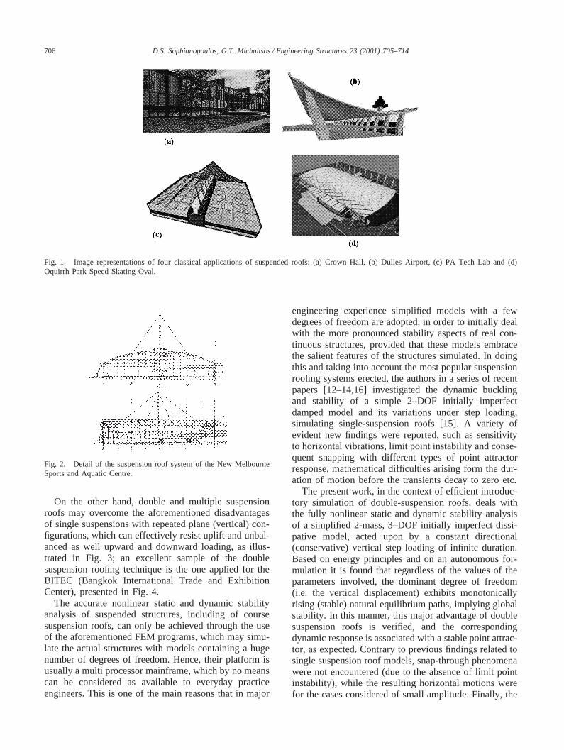
The last 15 years in particular, the advent of powerfulcomputers and the development of sophisticated nonlin-ear FEM software (ADINA, ABAQUS and others) haveenabled engineers to utilize suspension roofs in compli-cated large scale structures, some of which can be classi-fied among unique examples of engineering excellence.A comparative presentation of earlier and recent appli-cations of suspension roofs is shown in Fig. 1, wherethe last image (Fig. 1(d)) refers to the Oquirrh ParkSpeed Skating Oval, belonging to the facilities of theSalt Lake City cite for the XIX Olympic Winter Gamesof 2002.
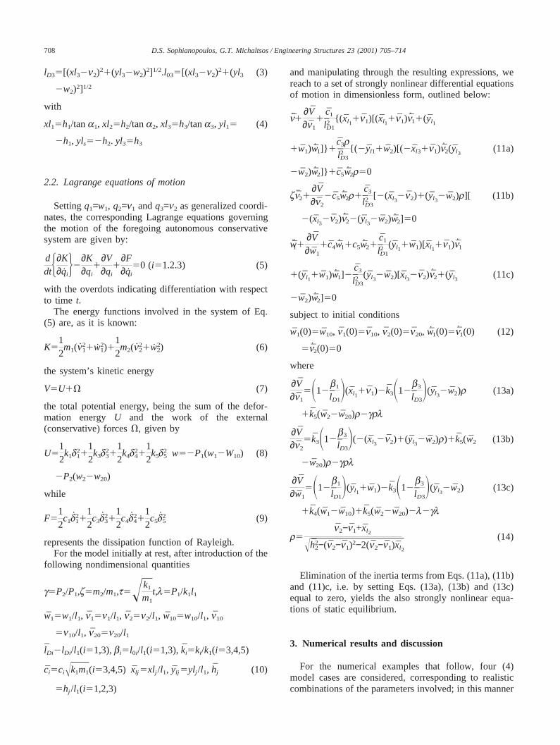
More specifically, single suspended roofing systemsused worldwide require three-dimensional suspensionsand transverse stiffening, since for rather obviousreasons they are sensitive to horizontal vibrations andmay lose their stability due to dynamic snap-through [7–9]. A characteristic example of such a system is the oneused for the New Melbourne Sports and Aquatic Centre,depicted schematically in Fig. 2.
706 D.S. Sophianopoulos, G.T. Michaltsos / Engineering Structures 23 (2001) 705–714
Fig. 1. Image representations of four classical applications of suspended roofs: (a) Crown Hall, (b) Dulles Airport, (c) PA Tech Lab and (d)Oquirrh Park Speed Skating Oval.
Fig. 2. Detail of the suspension roof system of the New MelbourneSports and Aquatic Centre.
On the other hand, double and multiple suspensionroofs may overcome the aforementioned disadvantagesof single suspensions with repeated plane (vertical) con-figurations, which can effectively resist uplift and unbal-anced as well upward and downward loading, as illus-trated in Fig. 3; an excellent sample of the doublesuspension roofing technique is the one applied for theBITEC (Bangkok International Trade and ExhibitionCenter), presented in Fig. 4.
The accurate nonlinear static and dynamic stabilityanalysis of suspended structures, including of coursesuspension roofs, can only be achieved through the useof the aforementioned FEM programs, which may simu-late the actual structures with models containing a hugenumber of degrees of freedom. Hence, their platform isusually a multi processor mainframe, which by no meanscan be considered as available to everyday practiceengineers. This is one of the main reasons that in major
engineering experience simplified models with a fewdegrees of freedom are adopted, in order to initially dealwith the more pronounced stability aspects of real con-tinuous structures, provided that these models embracethe salient features of the structures simulated. In doingthis and taking into account the most popular suspensionroofing systems erected, the authors in a series of recentpapers [12–14,16] investigated the dynamic bucklingand stability of a simple 2–DOF initially imperfectdamped model and its variations under step loading,simulating single-suspension roofs [15]. A variety ofevident new findings were reported, such as sensitivityto horizontal vibrations, limit point instability and conse-quent snapping with different types of point attractorresponse, mathematical difficulties arising form the dur-ation of motion before the transients decay to zero etc.
The present work, in the context of efficient introduc-tory simulation of double-suspension roofs, deals withthe fully nonlinear static and dynamic stability analysisof a simplified 2-mass, 3–DOF initially imperfect dissi-pative model, acted upon by a constant directional(conservative) vertical step loading of infinite duration.Based on energy principles and on an autonomous for-mulation it is found that regardless of the values of theparameters involved, the dominant degree of freedom(i.e. the vertical displacement) exhibits monotonicallyrising (stable) natural equilibrium paths, implying globalstability. In this manner, this major advantage of doublesuspension roofs is verified, and the correspondingdynamic response is associated with a stable point attrac-tor, as expected. Contrary to previous findings related tosingle suspension roof models, snap-through phenomenawere not encountered (due to the absence of limit pointinstability), while the resulting horizontal motions werefor the cases considered of small amplitude. Finally, the

707D.S. Sophianopoulos, G.T. Michaltsos / Engineering Structures 23 (2001) 705–714
Fig. 3. Ground view and details of the double-suspension roofing system of the Bangkok International Trade and Exhibition Center (BITEC).
Fig. 4. Graphic details of double and multiple roof suspension sys-tems.
only difficulty emerging in the straightforward dynamicanalysis employed was the need of very small numericalintegration steps, which resulted to huge output datafiles; these however were adequately treated with the aidof modern commercial mathematical and graphicssoftware.
2. Mathematical formulation
2.1. Geometric considerations
Let us consider the dissipative, initially imperfect sys-tem shown in Fig. 5, used in the present study as a sim-ple elementary simulation of double-suspension roofs[15]. It consists of four (4) linear springski with corre-sponding dashpotsci (i=1,2,4,5) and two concentratedmassesm1 andm2 interconnected via a weightless rigidbar. Supports A andD are immovable hinges, while Eand Z may freely slide along horizontal tracks; thussprings 4 and 5 remain vertical throughout deformation.Configuration ABGDEZ depicted in the aforementionedFigure is considered slightly imperfect, i.e. the centersof both masses have already undergone a small initial
Fig. 5. Proposed 3–DOF autonomous damped model, simulating adouble-suspension roof, under step loading.
deformationn10, w10 andn20, w20 respectively, for whichall springs are thought to be unstressed. Furthermore,due to the rigidity of bar BG, one may readily write
w25h21w11Îh22+(n2−n1)2−2(n2−n1)(h2/tana2) (1)
which implies that the system under consideration hasthree (3) degrees of freedom. Clearly, Eq. (1) is alsovalid for the initial imperfections.
In the sequel, if under the action of step loadsP1 andP2 the system yields to a new equilibrium position,characterized by displacement componentsw1, n1, w2,n2, it is evident that the change of the springs length,measured from the initial slightly imperfect (trivial)state, can be written as follows:
d15lD12l01, d35lD32l03, d45w12w01, d55w2 (2)
2w02
where
lD15[(xl11n1)21(yl11w1)2]1/2.l015[(xl11n10)21(yl1
1w10)2]1/2
708 D.S. Sophianopoulos, G.T. Michaltsos / Engineering Structures 23 (2001) 705–714
lD35[(xl32n2)21(yl32w2)2]1/2.l035[(xl32n2)21(yl3 (3)
2w2)2]1/2
with
xl15h1/tana1, xl25h2/tana2, xl35h3/tana3, yl15 (4)
2h1, yls52h2. yl35h3
2.2. Lagrange equations of motion
Settingq1=w1, q2=n1 andq3=n2 as generalized coordi-nates, the corresponding Lagrange equations governingthe motion of the foregoing autonomous conservativesystem are given by:
ddtH∂K
∂qiJ2
∂K∂qi
1∂V∂qi
1∂F∂qi
50 (i51.2.3) (5)
with the overdots indicating differentiation with respectto time t.
The energy functions involved in the system of Eq.(5) are, as it is known:
K512m1(n2
11w21)1
12m2(n2
21w22) (6)
the system’s kinetic energy
V5U1V (7)
the total potential energy, being the sum of the defor-mation energy U and the work of the external(conservative) forcesV, given by
U512k1d2
1112k3d2
3112k4d2
4112k5d2
5 w52P1(w12W10) (8)
2P2(w22w20)
while
F512c1d2
1112c3d2
3112c4d2
4112c5d2
5 (9)
represents the dissipation function of Rayleigh.For the model initially at rest, after introduction of the
following nondimensional quantities
g5P2/P1,z5m2/m1,t5!k1
m1
t,l5P1/k1l1
w15w1/l1, n15n1/l1, n25n2/l1, w105w10/l1, n10
5n10/l1, n205n20/l1
lDi2lDi/l1(i51,3),bi5l0i/l1(i51,3), ki5ki/k1(i53,4,5)
ci5ciÎk1m1(i53,4,5) xlj 5xlj /l1, ylj 5ylj /l1, hj (10)
5hj /l1(i51,2,3)
and manipulating through the resulting expressions, wereach to a set of strongly nonlinear differential equationsof motion in dimensionless form, outlined below:
n1∂V∂n1
1c1
l2D1{( xl1
1n1)[(xl11n1)n11(yl1
1w1)w1]} 1c3rl2D3
{( 2yl11w2)[(2xl31n1)n2(yl3(11a)
2w2)w2]} 1c5w2r50
zn21∂V∂n2
2c5w2r1c3
l2D3
[2(xl32n2)1(yl3
2w2)r][ (11b)
2(xl32n2)n22(yl3
2w2)w2]50
w11∂V∂w1
1c4w11c5w21c1
l2D1
(yl11w1)[xl1
1n1)n1
1(yl11w1)w1]2
c3
l2D3(yl3
2w2)[xl32n2)n21(yl3
(11c)
2w2)w2]50
subject to initial conditions
w1(0)5w10, n1(0)5n10, n2(0)5n20, w1(0)5n1(0) (12)
5n2(0)50
where
∂V∂n1
5S12b1
lD1D(xl1
1n1)2k3S12b3
lD3D(yl3
2w2)r (13a)
1k5(w22w20)r2grl
∂V∂n2
5k3S12b3
lD3D(2(xl3
2n2)1(yl32w2)r)1k5(w2 (13b)
2w20)r2grl
∂V∂w1
5S12b1
lD1D(yl1
1w1)2k3S12b3
lD3D(yl3
2w2) (13c)
1k4(w12w10)1k5(w22w20)2l2gl
r5n2−n1+xl2
Îh22−(n2−n1)2−2(n2−n1)xl2
(14)
Elimination of the inertia terms from Eqs. (11a), (11b)and (11)c, i.e. by setting Eqs. (13a), (13b) and (13c)equal to zero, yields the also strongly nonlinear equa-tions of static equilibrium.
3. Numerical results and discussion
For the numerical examples that follow, four (4)model cases are considered, corresponding to realisticcombinations of the parameters involved; in this manner
709D.S. Sophianopoulos, G.T. Michaltsos / Engineering Structures 23 (2001) 705–714
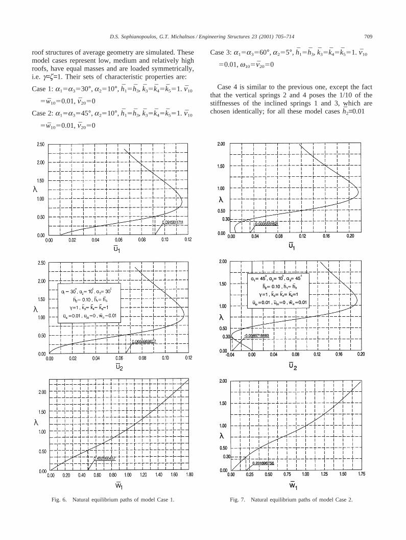
roof structures of average geometry are simulated. Thesemodel cases represent low, medium and relatively highroofs, have equal masses and are loaded symmetrically,i.e. g=z=1. Their sets of characteristic properties are:
Case 1:a15a3530°, a2510°, h15h3, k35k45k551. n10
5w1050.01,n2050
Case 2:a15a3545°, a2510°, h15h3, k35k45k551. n10
5w1050.01,n2050
Fig. 6. Natural equilibrium paths of model Case 1.
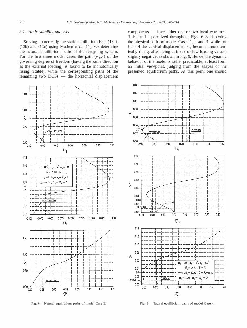
Case 3:a15a3560°, a255°, h15h3, k35k45k551. n10
50.01,w105n2050
Case 4 is similar to the previous one, except the factthat the vertical springs 2 and 4 poses the 1/10 of thestiffnesses of the inclined springs 1 and 3, which arechosen identically; for all these model casesh2=0.01
Fig. 7. Natural equilibrium paths of model Case 2.
710 D.S. Sophianopoulos, G.T. Michaltsos / Engineering Structures 23 (2001) 705–714
3.1. Static stability analysis
Solving numerically the static equilibrium Eqs. (13a),(13b) and (13c) using Mathematica [11], we determinethe natural equilibrium paths of the foregoing system.For the first three model cases the path (w1,l) of thegoverning degree of freedom (having the same directionas the external loading) is found to be monotonicallyrising (stable), while the corresponding paths of theremaining two DOFs — the horizontal displacement
Fig. 8. Natural equilibrium paths of model Case 3.
components — have either one or two local extremes.This can be perceived throughout Figs. 6–8, depictingthe physical paths of model Cases 1, 2 and 3, while forCase 4 the vertical displacementw1 becomes monoton-ically rising, after being at first (for low loading values)slightly negative, as shown in Fig. 9. Hence, the dynamicbehavior of the model is rather predictable, at least froman initial viewpoint, judging from the shapes of thepresented equilibrium paths. At this point one should
Fig. 9. Natural equilibrium paths of model Case 4.
711D.S. Sophianopoulos, G.T. Michaltsos / Engineering Structures 23 (2001) 705–714
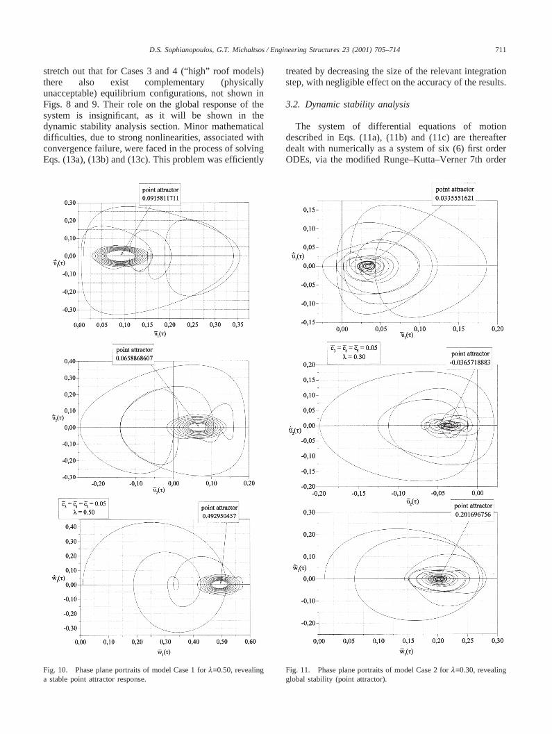
stretch out that for Cases 3 and 4 (“high” roof models)there also exist complementary (physicallyunacceptable) equilibrium configurations, not shown inFigs. 8 and 9. Their role on the global response of thesystem is insignificant, as it will be shown in thedynamic stability analysis section. Minor mathematicaldifficulties, due to strong nonlinearities, associated withconvergence failure, were faced in the process of solvingEqs. (13a), (13b) and (13c). This problem was efficiently
Fig. 10. Phase plane portraits of model Case 1 forl=0.50, revealinga stable point attractor response.
treated by decreasing the size of the relevant integrationstep, with negligible effect on the accuracy of the results.
3.2. Dynamic stability analysis
The system of differential equations of motiondescribed in Eqs. (11a), (11b) and (11c) are thereafterdealt with numerically as a system of six (6) first orderODEs, via the modified Runge–Kutta–Verner 7th order
Fig. 11. Phase plane portraits of model Case 2 forl=0.30, revealingglobal stability (point attractor).
712 D.S. Sophianopoulos, G.T. Michaltsos / Engineering Structures 23 (2001) 705–714
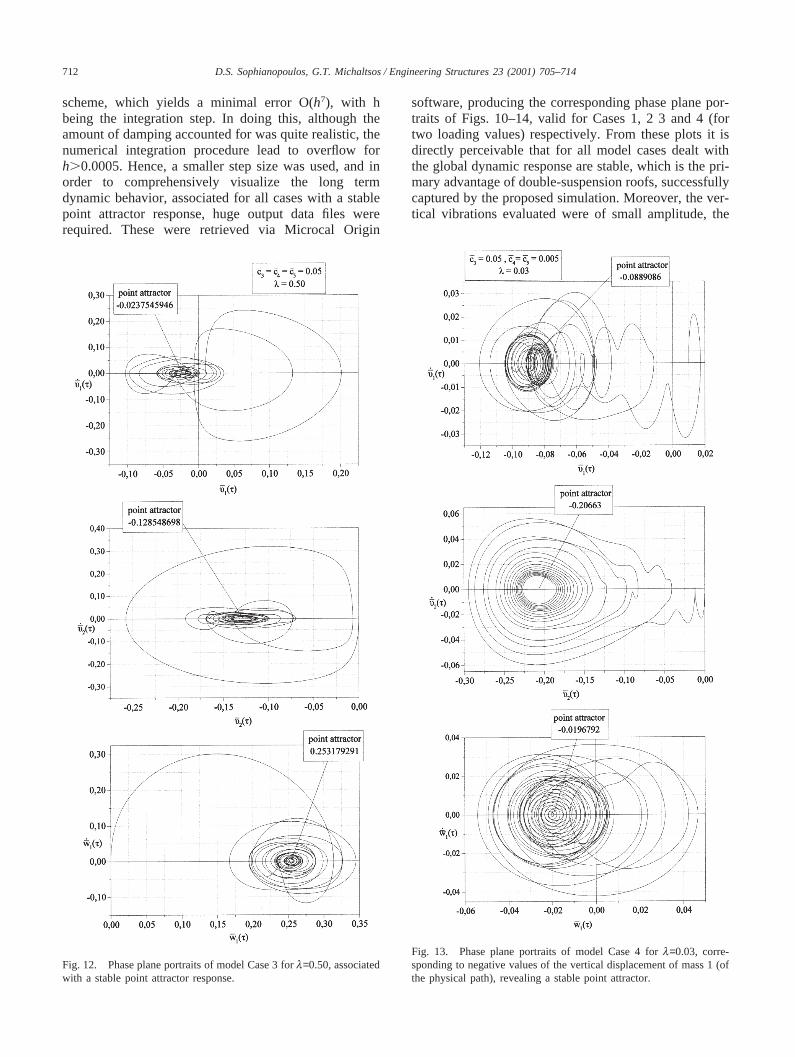
scheme, which yields a minimal error O(h7), with hbeing the integration step. In doing this, although theamount of damping accounted for was quite realistic, thenumerical integration procedure lead to overflow forh.0.0005. Hence, a smaller step size was used, and inorder to comprehensively visualize the long termdynamic behavior, associated for all cases with a stablepoint attractor response, huge output data files wererequired. These were retrieved via Microcal Origin
Fig. 12. Phase plane portraits of model Case 3 forl=0.50, associatedwith a stable point attractor response.
software, producing the corresponding phase plane por-traits of Figs. 10–14, valid for Cases 1, 2 3 and 4 (fortwo loading values) respectively. From these plots it isdirectly perceivable that for all model cases dealt withthe global dynamic response are stable, which is the pri-mary advantage of double-suspension roofs, successfullycaptured by the proposed simulation. Moreover, the ver-tical vibrations evaluated were of small amplitude, the
Fig. 13. Phase plane portraits of model Case 4 forl=0.03, corre-sponding to negative values of the vertical displacement of mass 1 (ofthe physical path), revealing a stable point attractor.
713D.S. Sophianopoulos, G.T. Michaltsos / Engineering Structures 23 (2001) 705–714
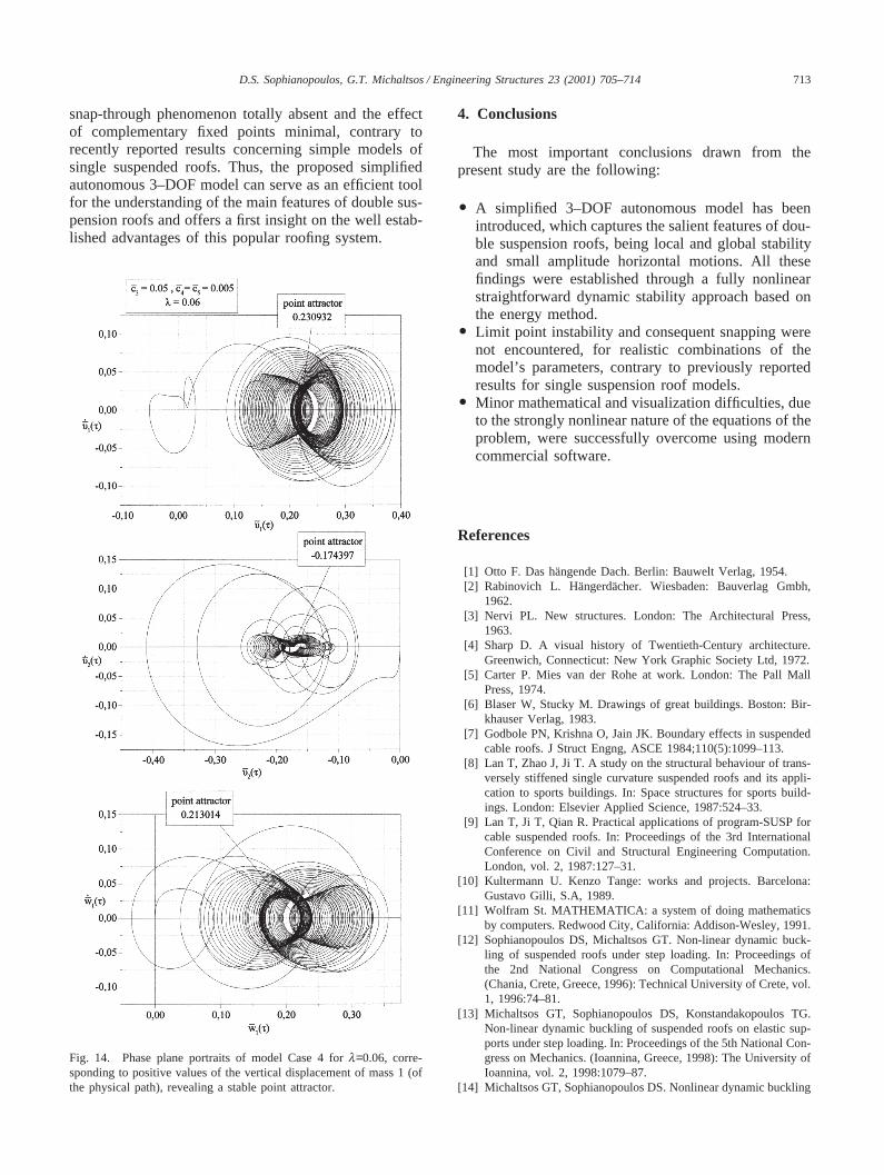
snap-through phenomenon totally absent and the effectof complementary fixed points minimal, contrary torecently reported results concerning simple models ofsingle suspended roofs. Thus, the proposed simplifiedautonomous 3–DOF model can serve as an efficient toolfor the understanding of the main features of double sus-pension roofs and offers a first insight on the well estab-lished advantages of this popular roofing system.
Fig. 14. Phase plane portraits of model Case 4 forl=0.06, corre-sponding to positive values of the vertical displacement of mass 1 (ofthe physical path), revealing a stable point attractor.
4. Conclusions
The most important conclusions drawn from thepresent study are the following:
O A simplified 3–DOF autonomous model has beenintroduced, which captures the salient features of dou-ble suspension roofs, being local and global stabilityand small amplitude horizontal motions. All thesefindings were established through a fully nonlinearstraightforward dynamic stability approach based onthe energy method.
O Limit point instability and consequent snapping werenot encountered, for realistic combinations of themodel’s parameters, contrary to previously reportedresults for single suspension roof models.
O Minor mathematical and visualization difficulties, dueto the strongly nonlinear nature of the equations of theproblem, were successfully overcome using moderncommercial software.
References
[1] Otto F. Das ha¨ngende Dach. Berlin: Bauwelt Verlag, 1954.[2] Rabinovich L. Hangerdacher. Wiesbaden: Bauverlag Gmbh,
1962.[3] Nervi PL. New structures. London: The Architectural Press,
1963.[4] Sharp D. A visual history of Twentieth-Century architecture.
Greenwich, Connecticut: New York Graphic Society Ltd, 1972.[5] Carter P. Mies van der Rohe at work. London: The Pall Mall
Press, 1974.[6] Blaser W, Stucky M. Drawings of great buildings. Boston: Bir-
khauser Verlag, 1983.[7] Godbole PN, Krishna O, Jain JK. Boundary effects in suspended
cable roofs. J Struct Engng, ASCE 1984;110(5):1099–113.[8] Lan T, Zhao J, Ji T. A study on the structural behaviour of trans-
versely stiffened single curvature suspended roofs and its appli-cation to sports buildings. In: Space structures for sports build-ings. London: Elsevier Applied Science, 1987:524–33.
[9] Lan T, Ji T, Qian R. Practical applications of program-SUSP forcable suspended roofs. In: Proceedings of the 3rd InternationalConference on Civil and Structural Engineering Computation.London, vol. 2, 1987:127–31.
[10] Kultermann U. Kenzo Tange: works and projects. Barcelona:Gustavo Gilli, S.A, 1989.
[11] Wolfram St. MATHEMATICA: a system of doing mathematicsby computers. Redwood City, California: Addison-Wesley, 1991.
[12] Sophianopoulos DS, Michaltsos GT. Non-linear dynamic buck-ling of suspended roofs under step loading. In: Proceedings ofthe 2nd National Congress on Computational Mechanics.(Chania, Crete, Greece, 1996): Technical University of Crete, vol.1, 1996:74–81.
[13] Michaltsos GT, Sophianopoulos DS, Konstandakopoulos TG.Non-linear dynamic buckling of suspended roofs on elastic sup-ports under step loading. In: Proceedings of the 5th National Con-gress on Mechanics. (Ioannina, Greece, 1998): The University ofIoannina, vol. 2, 1998:1079–87.
[14] Michaltsos GT, Sophianopoulos DS. Nonlinear dynamic buckling

714 D.S. Sophianopoulos, G.T. Michaltsos / Engineering Structures 23 (2001) 705–714
of asymmetrical suspended roofs under step loading. Comp Mech1998;21(4/5):389–97.
[15] Michaltsos GT, Sophianopoulos DS. Nonlinear dynamic stabilityof 3-D.O.F. imperfect damped system under step loading. In: Pro-ceedings of the 3rd National Congress on Computational Mech-
anics. (Volos, Greece, 1999): University of Thessaly, vol. 1,1999:273–80.
[16] Sophianopoulos DS. Point attractors and dynamic buckling ofautonomous systems under step loading. Int J Solids Struct1999;36(35):5357–85.