99ssp_template - · web view10 1.24 traffic control system for lane closure 137 stationary...
TRANSCRIPT

** WARNING ** WARNING ** WARNING ** WARNING **This document is intended for informational purposes only.
Users are cautioned that California Department of Transportation (Department) does not assume any liability or responsibility based on these electronic files or for any defective or incomplete copying, exerpting, scanning, faxing or downloading of the contract documents. As always, for the official paper versions of the bidders packages and non-bidder packages, including addenda write to the California Department of Transportation, Plans and Bid Documents, Room 0200, P.O. Box 942874, Sacramento, CA 94272-0001, telephone (916) 654-4490 or fax (916) 654-7028. Office hours are 7:30 a.m. to 4:15 p.m. When ordering bidder or non-bidder packages it is important that you include a telephone number and fax number, P.O. Box and street address so that you can receive addenda.
etric
Caltrans
STATE OF CALIFORNIA
DEPARTMENT OF TRANSPORTATION__________________________________________________________
NOTICE TO CONTRACTORSAND
SPECIAL PROVISIONSFOR CONSTRUCTION ON STATE HIGHWAY IN
SAN DIEGO COUNTY AT VARIOUS LOCATIONS
DISTRICT 11, ROUTES 5,56,805
__________________________________________________________
For Use in Connection with Standard Specifications Dated JULY 1999, Standard Plans Dated JULY 1999, and Labor Surcharge and Equipment Rental Rates.
__________________________________________________________
CONTRACT NO. 11-0301U4
11-SD-5,56,805-Var

Federal Aid Project
ACIM-X073(059)N
STPL-6066(039)N
Bids Open: December 6, 2001 OSDDated: October 1, 2001

*************************************************************************************************
IMPORTANTSPECIAL NOTICES
*************************************************************************************************
This project includes, but is not limited to, the following special requirements:
Bidder inquiries are to be directed to the District Construction Office at:Telephone No.: (619) 688-6635FAX No.: (619) 688-6988
Attention is directed to the Notice to Contractors regarding the bid opening location.
Attention is directed to Section 4, "Beginning of Work, Time of Completion and Liquidated Damages," of these Special Provisions regarding beginning of work restrictions.
The bidder's attention is directed to Section 5, containing specifications for "Disputes Review Board," of the Special Provisions, regarding establishing a Disputes Review Board (DRB) for the project.
Attention is directed to "Miscellaneous Metal," in Section 8-1, "Miscellaneous," of these Special Provisions for new requirements for miscellaneous metal.
The Special Provisions for Federal-aid projects (with and without DBE goals) have been revised to incorporate changes made by new regulations governing the DBE Program (49 CFR Part 26).
Sections 2 and 5 incorporate the changes. Bidders should read these sections to become familiar with them. Attention is directed to the following significant changes:
Section 2, "Disadvantaged Business Enterprise (DBE)" revises the counting of participation by DBE primes, and the counting of trucking performed by DBE firms. The section also revises the information that must be submitted to the Department in order to receive credit for trucking.
Section 2, "Submission of DBE Information" revises the information required to be submitted to the Department to receive credit toward the DBE goal. It also revises the criteria to demonstrate good faith efforts.
Section 5, "Subcontractor and DBE Records" revises the information required to be reported at the end of the project, and information related to trucking that must be submitted throughout the project.
Section 5, "DBE Certification Status" adds new reporting requirements related to DBE certification.
Section 5, "Subcontracting" describes the efforts that must be made in the event a DBE subcontractor is terminated or fails to complete its work for any reason.

Section 5, "Prompt Progress Payment to Subcontractors" requires prompt payment to all subcontractors.
Section 5, "Prompt Payment of Withheld Funds to Subcontractors" requires the prompt payment of retention to all subcontractors.
Payment BondsAttention is directed to Section 5 of the Special Provisions, regarding contract bonds. The payment bond shall be in a sum not less than one hundred percent of the total amount payable by the terms of the contract.
Attention is directed to Section 11-2, "Portland Cement Concrete," of these Special Provisions which contains Section 90, "Portland Cement Concrete," of the Standard Specifications.
Attention is directed to "Miscellaneous Metal," in Section 8-1, "Miscellaneous," of these Special Provisions for new requirements for miscellaneous metal.

TABLE OF CONTENTS
NOTICE TO CONTRACTORS.............................................................................................................................................1COPY OF ENGINEER'S ESTIMATE..................................................................................................................................3SPECIAL PROVISIONS.....................................................................................................................................................18SECTION 1. SPECIFICATIONS AND PLANS................................................................................................................18SECTION 2. PROPOSAL REQUIREMENTS AND CONDITIONS................................................................................18
2-1.01 GENERAL........................................................................................................................................................182-1.015 FEDERAL LOBBYING RESTRICTIONS...................................................................................................182-1.02 DISADVANTAGED BUSINESS ENTERPRISE (DBE)................................................................................192-1.02A DBE GOAL FOR THIS PROJECT...............................................................................................................202-1.02B SUBMISSION OF DBE INFORMATION...................................................................................................212-1.03 ESCROW OF BID DOCUMENTATION........................................................................................................22
SECTION 3. AWARD AND EXECUTION OF CONTRACT..........................................................................................23SECTION 4. BEGINNING OF WORK, TIME OF COMPLETION AND LIQUIDATED DAMAGES.........................24SECTION 5. GENERAL....................................................................................................................................................24SECTION 5-1. MISCELLANEOUS..................................................................................................................................24
5-1.01 PLANS AND WORKING DRAWINGS.........................................................................................................245-1.011 EXAMINATION OF PLANS, SPECIFICATIONS, CONTRACT, AND SITE OF WORK.......................255-1.012 DIFFERING SITE CONDITIONS.................................................................................................................255-1.015 LABORATORY.............................................................................................................................................255-1.017 CONTRACT BONDS....................................................................................................................................255-1.018 EXCAVATION SAFETY PLANS................................................................................................................255-1.019 COST REDUCTION INCENTIVE................................................................................................................265-1.02 LABOR NONDISCRIMINATION..................................................................................................................265-1.03 INTEREST ON PAYMENTS..........................................................................................................................265-1.031 FINAL PAYMENT AND CLAIMS..............................................................................................................275-1.04 PUBLIC SAFETY............................................................................................................................................275-1.05 SURFACE MINING AND RECLAMATION ACT........................................................................................285-1.06 REMOVAL OF ASBESTOS AND HAZARDOUS SUBSTANCES..............................................................285-1.07 YEAR 2000 COMPLIANCE...........................................................................................................................285-1.075 BUY AMERICA REQUIREMENTS.............................................................................................................295-1.08 SUBCONTRACTOR AND DBE RECORDS.................................................................................................295-1.083 DBE CERTIFICATION STATUS.................................................................................................................295-1.086 PERFORMANCE OF DBE SUBCONTRACTORS AND SUPPLIERS......................................................305-1.09 SUBCONTRACTING......................................................................................................................................305-1.10 PROMPT PROGRESS PAYMENT TO SUBCONTRACTORS....................................................................315-1.102 PROMPT PAYMENT OF WITHHELD FUNDS TO SUBCONTRACTORS.............................................315-1.11 PARTNERING.................................................................................................................................................315–1.114 VALUE ANALYSIS.....................................................................................................................................315-1.12 DISPUTE REVIEW BOARD..........................................................................................................................32
DISPUTES INVOLVING SUBCONTRACTOR CLAIMS.................................................................................355-1.13 ENVIRONMENTALLY SENSITIVE AREA (ESA)......................................................................................415-1.14 BIOLOGIST.....................................................................................................................................................415-1.15 FORCE ACCOUNT PAYMENT.....................................................................................................................415-1.16 CLAIMS SUBMITTAL...................................................................................................................................425-1.17 COMPENSATION ADJUSTMENTS FOR PRICE INDEX FLUCTUATIONS............................................425-1.18 AREAS FOR CONTRACTOR'S USE.............................................................................................................435-1.19 PAYMENTS.....................................................................................................................................................435-1.20 SOUND CONTROL REQUIREMENTS.........................................................................................................445-1.21 RELATIONS WITH CALIFORNIA DEPARTMENT OF FISH AND GAME.............................................455-1.22 RELATIONS WITH U.S. ARMY CORPS OF ENGINEERS.........................................................................455-1.23 RELATIONS WITH CALIFORNIA COASTAL COMMISSION.................................................................465-1.24 AERIALLY DEPOSITED LEAD....................................................................................................................46
SECTION 6. INCENTIVES AND DISINCENTIVES FOR COMPLETION OF WORK................................................47DESIGNATED PORTION OF WORK.................................................................................................................47
Contract No. 11-0301U41
INCENTIVE AND DISINCENTIVE....................................................................................................................47SECTION 7. (BLANK).......................................................................................................................................................47SECTION 8. MATERIALS................................................................................................................................................47SECTION 8-1. MISCELLANEOUS..................................................................................................................................47
8-1.01 SUBSTITUTION OF NON-METRIC MATERIALS AND PRODUCTS......................................................478-1.02 PREQUALIFIED AND TESTED SIGNING AND DELINEATION MATERIALS.....................................538-1.03 STATE-FURNISHED MATERIALS..............................................................................................................588-1.04 SLAG AGGREGATE......................................................................................................................................598-1.05 MISCELLANEOUS METAL..........................................................................................................................618-1.06 ENGINEERING FABRICS..............................................................................................................................62
SECTION 8-2. CONCRETE...............................................................................................................................................638-2.01 PORTLAND CEMENT CONCRETE.............................................................................................................638-2.02 CORROSION CONTROL FOR PORTLAND CEMENT CONCRETE.........................................................648-2.03 CEMENT AND WATER CONTENT.............................................................................................................65
SECTION 8-3. WELDING.................................................................................................................................................658-3.01 WELDING........................................................................................................................................................65
GENERAL.............................................................................................................................................................65WELDING QUALITY CONTROL......................................................................................................................67PAYMENT............................................................................................................................................................70
SECTION 9. DESCRIPTION OF BRIDGE WORK..........................................................................................................70SECTION 10. CONSTRUCTION DETAILS....................................................................................................................71SECTION 10-1. GENERAL...............................................................................................................................................71
10-1.00 CONSTRUCTION PROJECT INFORMATION SIGNS..............................................................................7110-1.01 ORDER OF WORK.......................................................................................................................................7210-1.02 WATER POLLUTION CONTROL (STORM WATER POLLUTION PREVENTION PLAN).................74
STORM WATER POLLUTION PREVENTION PLAN PREPARATION, APPROVAL AND AMENDMENTS................................................................................................................................................................................75COST BREAK-DOWN.........................................................................................................................................76SWPPP IMPLEMENTATION..............................................................................................................................78MAINTENANCE..................................................................................................................................................79WATER POLLUTION CONTROL TRAINING..................................................................................................79PAYMENT............................................................................................................................................................80
10-1.03 TEMPORARY EROSION CONTROL.........................................................................................................81MATERIALS.........................................................................................................................................................81APPLICATION.....................................................................................................................................................81MEASUREMENT AND PAYMENT...................................................................................................................81
10-1.04 TEMPORARY CULVERTS..........................................................................................................................8110-1.05 TEMPORARY FIBER ROLL........................................................................................................................82
MATERIALS.........................................................................................................................................................82INSTALLATION..................................................................................................................................................82MEASUREMENT AND PAYMENT...................................................................................................................82
10-1.06 TEMPORARY GRAVEL BAG.....................................................................................................................83MATERIALS.........................................................................................................................................................83INSTALLATION..................................................................................................................................................83MEASUREMENT AND PAYMENT...................................................................................................................83
10-1.07 TEMPORARY CONCRETE WASHOUT.....................................................................................................8310-1.08 TEMPORARY CONSTRUCTION ENTRANCE.........................................................................................8410-1.09 TEMPORARY FENCE AND GATES..........................................................................................................8410-1.10 TEMPORARY FENCE (TYPE ESA).............................................................................................................8510-1.11 PRESERVATION OF PROPERTY...............................................................................................................8610-1.12 RELIEF FROM MAINTENANCE AND RESPONSIBILITY.....................................................................8610-1.13 COOPERATION............................................................................................................................................8610-1.14 PROGRESS SCHEDULE (CRITICAL PATH METHOD)...........................................................................86
DEFINITIONS.......................................................................................................................................................86GENERAL REQUIREMENTS.............................................................................................................................87COMPUTER SOFTWARE...................................................................................................................................88NETWORK DIAGRAMS, REPORTS AND DATA............................................................................................89PRE-CONSTRUCTION SCHEDULING CONFERENCE..................................................................................90
Contract No. 11-0301U42

BASELINE SCHEDULE......................................................................................................................................90UPDATE SCHEDULE..........................................................................................................................................90TIME IMPACT ANALYSIS.................................................................................................................................91FINAL UPDATE SCHEDULE.............................................................................................................................91RETENTION.........................................................................................................................................................91PAYMENT............................................................................................................................................................91
10-1.15 OVERHEAD..................................................................................................................................................9210-1.16 OBSTRUCTIONS..........................................................................................................................................9410-1.17 DUST CONTROL..........................................................................................................................................9710-1.18 MOBILIZATION...........................................................................................................................................9710-1.19 CONSTRUCTION AREA TRAFFIC CONTROL DEVICES......................................................................9710-1.20 CONSTRUCTION AREA SIGNS.................................................................................................................9710-1.21 MAINTAINING TRAFFIC............................................................................................................................9810-1.22 CLOSURE REQUIREMENTS AND CONDITIONS................................................................................135
CLOSURE SCHEDULE.....................................................................................................................................136CONTINGENCY PLAN.....................................................................................................................................136LATE REOPENING OF CLOSURES................................................................................................................136COMPENSATION..............................................................................................................................................136
10-1.23 CONSTRUCTION ZONE ENHANCED ENFORCEMENT......................................................................13710-1.24 TRAFFIC CONTROL SYSTEM FOR LANE CLOSURE..........................................................................137
STATIONARY LANE CLOSURE.....................................................................................................................137MOVING LANE CLOSURE..............................................................................................................................138PAYMENT..........................................................................................................................................................138
10-1.25 TEMPORARY PAVEMENT DELINEATION...........................................................................................139GENERAL...........................................................................................................................................................139TEMPORARY LANELINE DELINEATION....................................................................................................139TEMPORARY EDGELINE DELINEATION....................................................................................................139TEMPORARY TRAFFIC STRIPE (PAINT)......................................................................................................140TEMPORARY PAVEMENT MARKING (PAINT)..........................................................................................140TEMPORARY PAVEMENT MARKERS..........................................................................................................141MEASUREMENT AND PAYMENT.................................................................................................................141
10-1.26 PORTABLE FLASHING BEACON...........................................................................................................14110-1.27 BARRICADE...............................................................................................................................................14210-1.28 PORTABLE CHANGEABLE MESSAGE SIGN........................................................................................14210-1.29 TEMPORARY RAILING............................................................................................................................14210-1.30 TRAFFIC PLASTIC DRUMS.....................................................................................................................14210-1.31 TEMPORARY CRASH CUSHION MODULE..........................................................................................14310-1.32 TEMPORARY CRASH CUSHION (ADIEM)............................................................................................14410-1.33 EXISTING HIGHWAY FACILITIES.........................................................................................................145
ABANDON CULVERT AND PIPE LINE.........................................................................................................145REMOVE FENCE...............................................................................................................................................146REMOVE METAL BEAM GUARD RAILING.................................................................................................146REMOVE PAVEMENT MARKER....................................................................................................................146REMOVE CABLE RAILING.............................................................................................................................146REMOVE TRAFFIC STRIPE AND PAVEMENT MARKING........................................................................146REMOVE CHANNELIZERS, MARKERS AND DELINEATORS..................................................................147REMOVE ASPHALT CONCRETE DIKE.........................................................................................................148REMOVE ROADSIDE SIGN.............................................................................................................................148REMOVE SIGN STRUCTURE..........................................................................................................................148REMOVE DRAINAGE FACILITY....................................................................................................................148RECONSTRUCT BRIDGE RAILING...............................................................................................................148RESET ROADSIDE SIGN..................................................................................................................................148RELOCATE ROADSIDE SIGN.........................................................................................................................149RELOCATE SIGN STRUCTURE......................................................................................................................149MODIFY INLET.................................................................................................................................................149MODIFY SIGN STRUCTURE...........................................................................................................................149REMOVE SURFACING.....................................................................................................................................149RETAINING WALL...........................................................................................................................................149
Contract No. 11-0301U43
COLD PLANE ASPHALT CONCRETE PAVEMENT.....................................................................................150REMOVE CONCRETE.......................................................................................................................................150CAP INLET.........................................................................................................................................................150BRIDGE REMOVAL (PORTION).....................................................................................................................150
10-1.34 CLEARING AND GRUBBING...................................................................................................................15210-1.35 WATERING.................................................................................................................................................15210-1.36 EARTHWORK.............................................................................................................................................15210-1.37 CONTROLLED LOW STRENGTH MATERIAL......................................................................................15510-1.38 MATERIAL CONTAINING AERIALLY DEPOSITED LEAD................................................................156
LEAD COMPLIANCE PLAN............................................................................................................................157EXCAVATION AND TRANSPORTATION PLAN.........................................................................................157DUST CONTROL...............................................................................................................................................158MATERIAL TRANSPORTATION....................................................................................................................158DISPOSAL..........................................................................................................................................................158MEASUREMENT AND PAYMENT.................................................................................................................158
10-1.39 PLANTABLE GEOSYNTHETIC REINFORCED WALL.........................................................................159MATERIALS.......................................................................................................................................................159EARTHWORK....................................................................................................................................................161PRECAST CONCRETE WALL FACE..............................................................................................................161CONSTRUCTION...............................................................................................................................................162RESEARCH ACTIVITIES..................................................................................................................................163MEASUREMENT...............................................................................................................................................164PAYMENT..........................................................................................................................................................164
10-1.40 STONE COLUMNS.....................................................................................................................................164MATERIALS.......................................................................................................................................................164CONSTRUCTION...............................................................................................................................................165MEASUREMENT AND PAYMENT.................................................................................................................168
10-1.41 SOIL-CEMENT............................................................................................................................................169DEEP-MIXING...................................................................................................................................................169SUBMITTALS....................................................................................................................................................169SOIL-CEMENT QUALITY CONTROL............................................................................................................171VIBRATION, GROUND MOVEMENT, AND NOISE.....................................................................................173CEMENT GROUT..............................................................................................................................................173SOIL-CEMENT...................................................................................................................................................173CONSTRUCTION...............................................................................................................................................174MEASUREMENT...............................................................................................................................................175PAYMENT..........................................................................................................................................................175
10-1.42 PREFABRICATED VERTICAL DRAIN...................................................................................................176MATERIAL.........................................................................................................................................................176SUBMITTALS....................................................................................................................................................176VIBRATION, GROUND MOVEMENT, AND NOISE MONITORING..........................................................177CONSTRUCTION...............................................................................................................................................177MEASUREMENT AND PAYMENT.................................................................................................................178
10-1.43 MOVE-IN/MOVE-OUT (EROSION CONTROL)......................................................................................17810-1.44 TEMPORARY EROSION CONTROL (TYPE 2 AND TYPE 3)...............................................................178
MATERIALS.......................................................................................................................................................178APPLICATION...................................................................................................................................................181MEASUREMENT AND PAYMENT.................................................................................................................182
10-1.45 IRRIGATION CROSSOVERS....................................................................................................................18210-1.46 EXTEND IRRIGATION CROSSOVERS...................................................................................................18210-1.47 IMPORTED TOPSOIL................................................................................................................................18210-1.48 TRANSPLANT EXISTING TREES............................................................................................................18310-1.49 FINISHING ROADWAY............................................................................................................................18310-1.50 AGGREGATE SUBBASE...........................................................................................................................18310-1.51 AGGREGATE BASE...................................................................................................................................18410-1.52 ASPHALT CONCRETE..............................................................................................................................18410-1.53 CONCRETE PAVEMENT (WITH DOWELED TRANSVERSE WEAKENED PLANE JOINTS).........188
GENERAL...........................................................................................................................................................188
Contract No. 11-0301U44

PREPAVING CONFERENCE............................................................................................................................188TEST STRIP........................................................................................................................................................188MATERIALS.......................................................................................................................................................189SUBMITTALS....................................................................................................................................................191INSTALLING TIE BARS...................................................................................................................................191DOWEL PLACEMENT......................................................................................................................................192CORE DRILLING FOR DOWEL PLACEMENT ALIGNMENT ASSURANCE TESTING..........................192LIQUID JOINT SEALANT INSTALLATION..................................................................................................193CONSTRUCTING TRANSVERSE CONTACT JOINTS..................................................................................193MEASUREMENT AND PAYMENT.................................................................................................................193
10-1.54 PILING.........................................................................................................................................................194GENERAL...........................................................................................................................................................194CAST-IN-DRILLED-HOLE CONCRETE PILES..............................................................................................195STEEL PIPE PILING..........................................................................................................................................206MEASUREMENT AND PAYMENT (PILING)................................................................................................208
10-1.55 PRESTRESSING CONCRETE....................................................................................................................20910-1.56 CONCRETE STRUCTURES.......................................................................................................................209
GENERAL...........................................................................................................................................................210FALSEWORK.....................................................................................................................................................210COST REDUCTION INCENTIVE PROPOSALS FOR CAST-IN-PLACE PRESTRESSED BOX GIRDER BRIDGES............................................................................................................................................................212DECK CLOSURE POURS..................................................................................................................................213SLIDING BEARINGS.........................................................................................................................................213ELASTOMERIC BEARING PADS....................................................................................................................213
10-1.57 PRECAST CONCRETE GIRDERS.............................................................................................................213PRECAST PRESTRESSED CONCRETE BRIDGE MEMBERS......................................................................214MEASUREMENT AND PAYMENT.................................................................................................................214
10-1.58 PTFE BEARING..........................................................................................................................................21410-1.59 PTFE SPHERICAL BEARING...................................................................................................................21710-1.60 TYPE 6 RETAINING WALL......................................................................................................................21910-1.61 STRUCTURE APPROACH SLABS (TYPE N)..........................................................................................220
GENERAL...........................................................................................................................................................220STRUCTURE APPROACH DRAINAGE SYSTEM.........................................................................................220ENGINEERING FABRICS.................................................................................................................................221TREATED PERMEABLE BASE UNDER APPROACH SLAB.......................................................................222APPROACH SLABS...........................................................................................................................................222JOINTS................................................................................................................................................................223MEASUREMENT AND PAYMENT.................................................................................................................223
10-1.62 STRUCTURE APPROACH SLABS (TYPE R)..........................................................................................223GENERAL...........................................................................................................................................................223TEMPORARY ROADWAY STRUCTURAL SECTION..................................................................................224REMOVING PORTIONS OF EXISTING STRUCTURES...............................................................................224REMOVING EXISTING PAVEMENT AND BASE MATERIALS.................................................................224AGGREGATE BASE (APPROACH SLAB)......................................................................................................224STRUCTURE APPROACH SLAB.....................................................................................................................225JOINTS................................................................................................................................................................226MEASUREMENT AND PAYMENT.................................................................................................................226
10-1.63 PAVING NOTCH EXTENSION.................................................................................................................22610-1.64 SEALING JOINTS.......................................................................................................................................22710-1.65 JOINT SEAL ASSEMBLIES (MAXIMUM MOVEMENT RATING, 100 MM)........................................227
ALTERNATIVE JOINT SEAL ASSEMBLY....................................................................................................22810-1.66 JOINT SEAL ASSEMBLIES (MOVEMENT RATING EXCEEDING 100 MM)......................................22910-1.67 ARCHITECTURAL SURFACE (TEXTURED CONCRETE)...................................................................230
RIVER ROCK TEXTURE..................................................................................................................................231TEST PANEL......................................................................................................................................................232CURING..............................................................................................................................................................232STUCCO TEXTURE...........................................................................................................................................232BROWN COAT...................................................................................................................................................232
Contract No. 11-0301U45

TEXTURE COAT...............................................................................................................................................232PLASTER PROPORTIONING AND MIXING.................................................................................................233PLASTER APPLICATION.................................................................................................................................233MEASUREMENT AND PAYMENT.................................................................................................................233
10-1.68 DRILL AND BOND DOWELS...................................................................................................................23310-1.69 REINFORCEMENT.....................................................................................................................................234
ULTIMATE BUTT SPLICES.............................................................................................................................234EPOXY-COATED PREFABRICATED REINFORCEMENT...........................................................................238MEASUREMENT AND PAYMENT.................................................................................................................239
10-1.70 COLUMN CASINGS....................................................................................................................................239CLEAN AND PAINT COLUMN CASING.......................................................................................................240GROUTING.........................................................................................................................................................243MEASUREMENT AND PAYMENT.................................................................................................................243
10-1.71 ISOLATION CASINGS...............................................................................................................................243MEASUREMENT AND PAYMENT.................................................................................................................244
10-1.72 SIGN STRUCTURES..................................................................................................................................24410-1.73 ROADSIDE SIGNS......................................................................................................................................24510-1.74 CLEAN AND PAINT STRUCTURAL STEEL..........................................................................................245
CLEANING.........................................................................................................................................................246PAINTING...........................................................................................................................................................247
10-1.75 PREPARE AND STAIN CONCRETE........................................................................................................24810-1.76 ALTERNATIVE PIPE.................................................................................................................................248
REINFORCED CONCRETE PIPE.....................................................................................................................248PLASTIC PIPE....................................................................................................................................................248
10-1.77 PLASTIC PIPE.............................................................................................................................................24810-1.78 REINFORCED CONCRETE PIPE..............................................................................................................24910-1.79 STRUCTURAL STEEL PLATE PIPE........................................................................................................24910-1.80 OVERSIDE DRAIN.....................................................................................................................................24910-1.81 MISCELLANEOUS FACILITIES...............................................................................................................24910-1.82 GRATED LINE DRAIN..............................................................................................................................24910-1.83 AUTOMATIC DRAINAGE GATE.............................................................................................................25110-1.84 SLOPE PROTECTION................................................................................................................................25110-1.85 SLOPE PAVING..........................................................................................................................................25110-1.86 MISCELLANEOUS CONCRETE CONSTRUCTION...............................................................................25110-1.87 MINOR CONCRETE (GUTTER)...............................................................................................................25310-1.88 MISCELLANEOUS IRON AND STEEL....................................................................................................25310-1.89 MISCELLANEOUS METAL (BRIDGE)....................................................................................................25310-1.90 BRIDGE DECK DRAINAGE SYSTEM.....................................................................................................254
MEASUREMENT AND PAYMENT.................................................................................................................25410-1.91 MISCELLANEOUS METAL (RESTRAINER-CABLE TYPE)................................................................25410-1.92 MISCELLANEOUS METAL (RESTRAINER-PIPE TYPE).....................................................................25410-1.93 CHAIN LINK FENCE.................................................................................................................................25510-1.94 MARKERS AND DELINEATORS.............................................................................................................25510-1.95 METAL BEAM GUARD RAILING...........................................................................................................255
TERMINAL SYSTEM (TYPE SRT)..................................................................................................................25510-1.96 CABLE RAILING........................................................................................................................................25610-1.97 CONCRETE BARRIER...............................................................................................................................25610-1.98 CRASH CUSHION (ADIEM).....................................................................................................................25610-1.99 CRASH CUSHION, SAND FILLED...........................................................................................................25610-1.100 THERMOPLASTIC TRAFFIC STRIPE AND PAVEMENT MARKING...............................................25710-1.101 PAINT TRAFFIC STRIPE AND PAVEMENT MARKING....................................................................25810-1.102 PAVEMENT MARKERS..........................................................................................................................258
SECTION 10-2. HIGHWAY PLANTING AND IRRIGATION SYSTEMS..................................................................25810-2.01 GENERAL....................................................................................................................................................258
COST BREAK-DOWN.......................................................................................................................................25810-2.02 EXISTING HIGHWAY PLANTING..........................................................................................................263
MAINTAIN EXISTING PLANTS......................................................................................................................263REMOVE EXISTING GROUND COVER........................................................................................................263
Contract No. 11-0301U46
REMOVE EXISTING PLANTS FOR TRENCHING........................................................................................263PRUNE EXISTING PLANTS.............................................................................................................................263PRUNE EXISTING TREES................................................................................................................................263
10-2.03 EXISTING HIGHWAY IRRIGATION FACILITIES.................................................................................264CHECK AND TEST EXISTING IRRIGATION FACILITIES..........................................................................264MAINTAIN EXISTING IRRIGATION FACILITIES.......................................................................................264REMOVE EXISTING IRRIGATION FACILITIES...........................................................................................264
10-2.04 HIGHWAY PLANTING..............................................................................................................................265HIGHWAY PLANTING MATERIALS.............................................................................................................265ROADSIDE CLEARING....................................................................................................................................265PESTICIDES.......................................................................................................................................................266PLANTING..........................................................................................................................................................267LINER PLANTS (PLANT GROUP M)..............................................................................................................267HYDROSEEDING..............................................................................................................................................267HYDROSEED 1 APPLICATION.......................................................................................................................271HYDROSEED 2 APPLICATION.......................................................................................................................271HYDROSEED 3 APPLICATION.......................................................................................................................271MEASUREMENT AND PAYMENT.................................................................................................................272PLANT ESTABLISHMENT WORK..................................................................................................................272
10-2.05 IRRIGATION SYSTEMS............................................................................................................................273VALVE BOXES..................................................................................................................................................273RE-LABEL EXISTING VALVE BOX COVER................................................................................................274ELECTRIC AUTOMATIC IRRIGATION COMPONENTS.............................................................................274RE-CIRCUIT EXISTING IRRIGATION CONTROLLERS..............................................................................277REMOTE CONTROL VALVE (MASTER) WITH FLOW METER................................................................277IRRIGATION SYSTEMS FUNCTIONAL TEST..............................................................................................278PIPE.....................................................................................................................................................................278WATER METER.................................................................................................................................................279BACKFLOW PREVENTER ASSEMBLIES......................................................................................................279BACKFLOW PREVENTER ASSEMBLY ENCLOSURE................................................................................279TESTING BACKFLOW PREVENTERS...........................................................................................................280SPRINKLERS......................................................................................................................................................280FERTILIZER COUPLING..................................................................................................................................280FINAL IRRIGATION SYSTEM CHECK..........................................................................................................280
SECTION 10-3. SIGNALS, LIGHTING AND ELECTRICAL SYSTEMS....................................................................28010-3.01 DESCRIPTION............................................................................................................................................28010-3.02 COST BREAK-DOWN................................................................................................................................28110-3.03 MAINTAINING EXISTING AND TEMPORARY ELECTRICAL SYSTEMS........................................28110-3.04 TEMPORARY LIGHTING..........................................................................................................................281
CONDUCTORS AND WIRING.........................................................................................................................281BONDING AND GROUNDING........................................................................................................................282SERVICE.............................................................................................................................................................282COMMERCIAL POWER...................................................................................................................................282GENERATOR.....................................................................................................................................................282GENERATOR OPERATION..............................................................................................................................282SALVAGING TEMPORARY LIGHTING........................................................................................................282PAYMENT..........................................................................................................................................................282
10-3.05 FOUNDATIONS..........................................................................................................................................28210-3.06 STANDARDS, STEEL PEDESTALS AND POSTS..................................................................................28310-3.07 CONDUIT....................................................................................................................................................28310-3.08 MULTIDUCT CONDUIT SYSTEM...........................................................................................................28410-3.09 COMMUNICATION CONDUIT................................................................................................................28410-3.10 HIGH DENSITY POLYETHYLENE CONDUIT.......................................................................................284
GENERAL...........................................................................................................................................................284MATERIAL.........................................................................................................................................................285CONDUIT............................................................................................................................................................285JOINING OF CONDUIT.....................................................................................................................................286INSTALLATION................................................................................................................................................286
Contract No. 11-0301U47

CERTIFICATES OF COMPLIANCE, MATERIALS RECEIVING INSPECTION AND MANUFACTURER'S DATA..................................................................................................................................................................287
10-3.11 SEALING PLUG..........................................................................................................................................28710-3.12 TRACER WIRE...........................................................................................................................................28710-3.13 WARNING TAPE........................................................................................................................................28710-3.14 SLURRY CEMENT BACKFILL.................................................................................................................28810-3.15 DIRECTIONAL BORING METHOD.........................................................................................................28810-3.16 PULL BOXES..............................................................................................................................................28810-3.17 FIBER OPTIC VAULT................................................................................................................................28810-3.18 HUB CABINET............................................................................................................................................28910-3.19 CATHODIC PROTECTION........................................................................................................................29010-3.20 CONDUCTORS AND WIRING..................................................................................................................291
SIGNAL INTERCONNECT CABLE.................................................................................................................291SIGNAL CABLE.................................................................................................................................................291OPTICAL DETECTOR CABLE.........................................................................................................................291
10-3.21 AIR BLOWN METHOD..............................................................................................................................29110-3.22 TRENCH DELINEATOR............................................................................................................................29210-3.23 SERVICE......................................................................................................................................................292
ELECTRIC SERVICE (IRRIGATION)..............................................................................................................29310-3.24 NUMBERING ELECTRICAL EQUIPMENT.............................................................................................29310-3.25 CLOSED CIRCUIT TELEVISION (CCTV) CABINETS...........................................................................29310-3.26 STATE-FURNISHED CONTROLLER ASSEMBLIES.............................................................................29410-3.27 TELEPHONE DEMARCATION CABINET..............................................................................................29410-3.28 IRRIGATION CONTROLLER ENCLOSURE CABINET.........................................................................29410-3.29 VEHICLE SIGNAL FACES AND SIGNAL HEADS................................................................................29510-3.30 LIGHT EMITTING DIODE SIGNAL MODULE.......................................................................................295
GENERAL...........................................................................................................................................................295PHYSICAL AND MECHANICAL REQUIREMENTS.....................................................................................295PHOTOMETRIC REQUIREMENTS.................................................................................................................297ELECTRICAL.....................................................................................................................................................299QUALITY CONTROL PROGRAM...................................................................................................................299CERTIFICATE OF COMPLIANCE...................................................................................................................300QUALITY ASSURANCE TESTING (RANDOM SAMPLE TESTING).........................................................300WARRANTY......................................................................................................................................................301
10-3.31 LIGHT EMITTING DIODE PEDESTRIAN SIGNAL FACE MODULES................................................301GENERAL...........................................................................................................................................................301PHOTOMETRIC REQUIREMENTS.................................................................................................................302ELECTRICAL.....................................................................................................................................................302QUALITY CONTROL PROGRAM...................................................................................................................303CERTIFICATE OF COMPLIANCE...................................................................................................................304QUALITY ASSURANCE TESTING (RANDOM SAMPLE TESTING).........................................................304WARRANTY......................................................................................................................................................304
10-3.32 DETECTORS...............................................................................................................................................30410-3.33 HIGH MAST LIGHTING ASSEMBLY......................................................................................................304
GENERAL...........................................................................................................................................................305SUBMITTALS....................................................................................................................................................305INSPECTION......................................................................................................................................................305CORROSION RESISTANCE.............................................................................................................................305POLE....................................................................................................................................................................305LUMINAIRE LOWERING DEVICE.................................................................................................................306LUMINAIRES.....................................................................................................................................................307BALLASTS.........................................................................................................................................................308HIGH PRESSURE SODIUM LAMPS................................................................................................................308
10-3.34 LUMINAIRES..............................................................................................................................................30810-3.35 PHOTOELECTRIC CONTROLS................................................................................................................30810-3.36 SIGN LIGHTING FIXTURES.....................................................................................................................30810-3.37 SIGN LIGHTING FIXTURES-INDUCTION.............................................................................................308
HOUSING............................................................................................................................................................308
Contract No. 11-0301U48

REFLECTOR.......................................................................................................................................................308REFRACTOR......................................................................................................................................................308LAMP..................................................................................................................................................................309POWER COUPLER............................................................................................................................................309HIGH FREQUENCY GENERATOR.................................................................................................................309
10-3.38 MODEL 500 CHANGEABLE MESSAGE SIGN SYSTEM......................................................................30910-3.39 FIBER OPTIC COMMUNICATION CABLE PLANT...............................................................................31010-3.40 FIBER OPTIC LABELING.........................................................................................................................31510-3.41 FIBER OPTIC CABLE INSTALLATION..................................................................................................31510-3.42 SPLICING....................................................................................................................................................31610-3.43 FIBER OPTIC SPLICE CLOSURE.............................................................................................................31610-3.44 SPLICE TRAY.............................................................................................................................................31710-3.45 PASSIVE CABLE ASSEMBLIES AND COMPONENTS.........................................................................31710-3.46 FIBER OPTIC CABLE TERMINATIONS.................................................................................................31710-3.47 FIBER OPTIC TESTING.............................................................................................................................31710-3.48 FIBER DISTRIBUTION UNIT...................................................................................................................32110-3.49 REMOVING, REINSTALLING OR SALVAGING ELECTRICAL EQUIPMENT.................................32110-3.50 PAYMENT...................................................................................................................................................321
SECTION 10-4. RELOCATION OF UTILITY FACILITIES.........................................................................................32210-4.01 GENERAL DESCRIPTION........................................................................................................................32210-4.02 EXCAVATION...........................................................................................................................................32210-4.03 TRENCH EXCAVATION..........................................................................................................................32210-4.04 WATER IN TRENCH.................................................................................................................................32210-4.05 EXCESS TRENCH EXCAVATION..........................................................................................................32310-4.06 ADDITIONAL BEDDING.........................................................................................................................32310-4.07 IMPORTED BACKFILL............................................................................................................................32310-4.08 TRENCH RESURFACING.........................................................................................................................32310-4.09 PIPE INSTALLATION...............................................................................................................................32310-4.10 BACKFILL..................................................................................................................................................32310-4.11 HANDLING AND STORAGE OF PVC WATER PIPE............................................................................32410-4.12 COORDINATION.......................................................................................................................................32410-4.13 BURIED WATER LINE WARNING AND IDENTIFICATION TAPE...................................................32410-4.14 EXISTING UTILITIES...............................................................................................................................32510-4.15 WATER FOR CONSTRUCTION PURPOSES..........................................................................................32510-4.16 COST OF WATER WITHIN THE CITY OF SAN DIEGO......................................................................32510-4.17 WATER SYSTEM RELOCATION.............................................................................................................326
GENERAL REQUIREMENTS...........................................................................................................................326WORK INVOLVED............................................................................................................................................326DRAWINGS AND DATA REQUIRED.............................................................................................................326CONNECTIONS TO WATER MAINS..............................................................................................................326CONNECTION AND SHUT DOWN.................................................................................................................326BEDDING FOR WATER MAINS......................................................................................................................326CONCRETE ANCHOR, VALVE AND THRUST BLOCKS............................................................................327WATER MAIN REMOVAL AND DISPOSAL.................................................................................................327ABANDON PIPELINE.......................................................................................................................................327SALVAGE FIRE HYDRANT.............................................................................................................................328MODIFY FIRE HYDRANT...............................................................................................................................328WATER SERVICES (NEW AND MODIFIED)................................................................................................328RELOCATE WATER METERS.........................................................................................................................328PIPE LAYING.....................................................................................................................................................328DISPOSAL OF ASBESTOS...............................................................................................................................329SHIPMENT AND STORAGE OF POLYVINYL CHLORIDE (PVC) PIPE....................................................329INSTALLATION OF POLYVINYL CHLORIDE (PVC) WATER PIPE.........................................................329STORAGE AND INSTALLATION OF VALVES............................................................................................330HYDROSTATIC TESTING OF MAINS............................................................................................................330TEST FOR PVC PRESSURE PIPE....................................................................................................................331AGENCY NOTIFICATION................................................................................................................................331MATERIALS.......................................................................................................................................................331
Contract No. 11-0301U49

COPPER TUBE FOR SERVICE LINES............................................................................................................334GATE AND BUTTERFLY VALVE PAINT CHART.......................................................................................335VALVE BOX AND EXTENSION STEM..........................................................................................................335DEWATERING PIPE AND FITTINGS.............................................................................................................335CONCRETE WATER METER BOXES.............................................................................................................336CORPORATION STOPS, CURB STOPS AND OTHER BRONZE WATER SERVICE FITTINGS.............336ONE HUNDRED AND FIFTY MILLIMETER FIRE HYDRANTS ASSEMBLY..........................................336WORK TO BE PERFORMED BY CITY OF SAN DIEGO..............................................................................337
SECTION 10-4.18 WATER PIPE RELOCATION MEASUREMENT AND PAYMENT............................................337MEASUREMENT...............................................................................................................................................337PAYMENT..........................................................................................................................................................337
10-4.19 APPROVED MATERIALS LIST................................................................................................................338SECTION 11. MODIFIED STANDARD SPECIFICATION SECTIONS......................................................................345SECTION 11-1. (BLANK)...............................................................................................................................................345SECTION 11-2. PORTLAND CEMENT CONCRETE...................................................................................................345SECTION 12. (BLANK)...................................................................................................................................................368SECTION 13. RAILROAD RELATIONS AND INSURANCE......................................................................................368SECTION 13-1. RELATIONS WITH RAILROAD COMPANY...................................................................................368
13-1.01 GENERAL..................................................................................................................................................36813-1.02 RAILROAD REQUIREMENTS.................................................................................................................36813-1.03 PROTECTION OF RAILROAD FACILITIES...........................................................................................36913-1.04 WORK BY RAILROAD COMPANY.........................................................................................................37013-1.05 DELAYS DUE TO WORK BY RAILROAD..............................................................................................37013-1.06 WORK BY CONTRACTOR.......................................................................................................................37013-1.07 LEGAL RELATIONS..................................................................................................................................37013-1.08........................................................................................................................................................................37013-1.09........................................................................................................................................................................37013-1.10 DELAY/CANCELLATION OF TRAINS...................................................................................................370
SECTION 13 -2. RAILROAD PROTECTIVE INSURANCE.........................................................................................371INSURANCE.......................................................................................................................................................371
SECTION 14. FEDERAL REQUIREMENTS FOR FEDERAL-AID CONSTRUCTION PROJECTS.........................373FEDERAL REQUIREMENT TRAINING SPECIAL PROVISIONS..............................................................................392
STANDARD PLANS LIST
The Standard Plan sheets applicable to this contract include, but are not limited to those indicated below. The Revised Standard Plans (RSP) and New Standard Plans (NSP) which apply to this contract are included as individual sheets of the project plans.
A10A AbbreviationsA10B SymbolsA20A Pavement Markers and Traffic Lines, Typical DetailsA20B Pavement Markers and Traffic Lines, Typical DetailsA20C Pavement Markers and Traffic Lines, Typical DetailsA20D Pavement Markers and Traffic Lines, Typical DetailsA24A Pavement Markings - ArrowsA24B Pavement Markings - ArrowsA24C Pavement Markings - Symbols and NumeralsA24D Pavement Markings - WordsA24E Pavement Markings - Words and CrosswalksRSP A35B Portland Cement Concrete Pavement (Doweled Transverse Joints)A35C Portland Cement Concrete Pavement Joint and End Anchor Details
Contract No. 11-0301U410

A62A Excavation and Backfill - Miscellaneous DetailsA62B Limits of Payment for Excavation and Backfill - Bridge Surcharge and WallA62C Limits of Payment for Excavation and Backfill - BridgeA73A Object MarkersA73B MarkersRSP A73C Delineators, Channelizers and BarricadesA76A Concrete Barrier Type 60A76B Concrete Barrier Type 60A76C Concrete Barrier Type 60EA76G Concrete Barrier Type 60SA77A Metal Beam Guard Railing – Typical Wood Post With Wood BlockA77AA Metal Beam Guard Railing – Typical Steel Post With Wood BlockA77B Metal Beam Guard Railing - Standard HardwareA77C Metal Beam Guard Railing – Wood Post and Wood Block DetailsA77D Metal Beam Guard Railing – Typical LayoutsA77E Metal Beam Guard Railing – Typical LayoutsA77F Metal Beam Guard Railing – Typical Embankment Widening for End TreatmentsA77FA Metal Beam Guard Railing – Typical Line Post InstallationRSP A77G Metal Beam Guard Railing – End Treatment, Terminal Anchor Assembly (Type SFT)A77H Metal Beam Guard Railing - Anchor Cable and Anchor Plate DetailsA77I Metal Beam Guard Railing – End Treatment, Terminal Anchor Assembly (Type CA)A77J Metal Beam Guard Railing Connections to Bridge Railings, Retaining Walls and
AbutmentsA77K Metal Beam Guard Railing Connections to Bridge Sidewalks and CurbsRSP A77L Metal Beam Guard Railing and Single Faced Barrier Railing Terminal System - End
TreatmentsA81A Crash Cushion, Sand Filled (Unidirectional)A82B Crash Cushion (Type ADIEM)A85 Chain Link FenceA87 Curbs, Dikes and DrivewaysA88A Curb Ramp DetailsRSP D72 Drainage InletsD73 Drainage InletsD74C Drainage Inlet DetailsD75A Pipe InletsD75B Pipe InletsD77A Grate DetailsD77B Bicycle Proof Grate DetailsD86C Arch Culvert Headwall, Endwall and Warped WingwallsRSP D89 Pipe HeadwallsD93A Pipe Riser ConnectionsD93B Drainage Inlet Riser ConnectionsD93C Pipe Riser With Debris Rack CageD97A Corrugated Metal Pipe Coupling Details No. 1 - Annular Coupling Band Bar and Strap and
Angle ConnectorsD97B Corrugated Metal Pipe Coupling Details No. 2 - Hat Band Coupler and Flange DetailsD97C Corrugated Metal Pipe Coupling Details No. 3 - Helical and Universal CouplersD97D Corrugated Metal Pipe Coupling Details No. 4 - Hugger Coupling BandsD97E Corrugated Metal Pipe Coupling Details No. 5 - Standard JointD97F Corrugated Metal Pipe Coupling Details No. 6 - Positive JointD97G Corrugated Metal Pipe Coupling Details No. 7 - Positive Joints and DowndrainsD97H Reinforced Concrete Pipe or Non-Reinforced Concrete Pipe - Standard and Positive JointsD98A Slotted Corrugated Steel Pipe Drain DetailsD98B Slotted Corrugated Steel Pipe Drain DetailsH1 Planting and Irrigation - AbbreviationsH2 Planting and Irrigation - Symbols
Contract No. 11-0301U411

H3 Planting and Irrigation DetailsH4 Planting and Irrigation DetailsH5 Planting and Irrigation DetailsH6 Planting and Irrigation DetailsH7 Planting and Irrigation DetailsH8 Planting and Irrigation DetailsT1A Temporary Crash Cushion, Sand Filled (Unidirectional)T1B Temporary Crash Cushion, Sand Filled (Bidirectional)RSP T2 Temporary Crash Cushion, Sand Filled (Shoulder Installations)T3 Temporary Railing (Type K)T7 Construction Project Funding Identification SignsT10 Traffic Control System for Lane Closure On Freeways and ExpresswaysT10A Traffic Control System for Lane and Complete Closures On Freeways and ExpresswaysT11 Traffic Control System for Lane Closure On Multilane Conventional HighwaysT14 Traffic Control System for Ramp ClosureT16 Traffic Control System for Moving Lane Closure On Multilane HighwaysB0-1 Bridge DetailsRSP B0-3 Bridge DetailsB0-5 Bridge DetailsB0-13 Bridge DetailsB2-5 Pile Details-Class 400 and Class 625RSP B3-1 Retaining Wall Type 1 - H=1200 Through 9100 mmRSP B3-2 Retaining Wall Type 1 - H=9700 Through 10 900 mmRSP B3-7 Retaining Wall Type 5RSP B3-8 Retaining Wall Details No. 1B3-9 Retaining Wall Details No. 2RSP B3-11 Retaining Wall Type 6 - 1829 mm MaximumB6-10 Utility Openings, T-BeamB6-21 Joint Seals (Maximum Movement Rating = 50 mm)B7-1 Box Girder DetailsB7-6 Deck Drains - Types D-1 and D-2B7-7 Deck Drain - Type D-3B7-10 Utility Opening - Box GirderB8-5 Cast-in-Place Prestressed Girder DetailsB11-47 Cable RailingRSP B11-53 Concrete Barrier Type 25B14-3 Communication and Sprinkler Control Conduits (Conduit Less Than size 103)B14-5 Water Supply Line (Details) (Pipe Sizes Less Than NPS 4)RS1 Roadside Signs, Typical Installation Details No. 1RS2 Roadside Signs - Wood Post, Typical Installation Details No. 2RS3 Roadside Signs - Laminated Wood Box Post Typical Installation Details No. 3RS4 Roadside Signs, Typical Installation Details No. 4RSP S1 Overhead Signs - Truss, Instructions and ExamplesRSP S2 Overhead Signs - Truss, Single Post Type - Post Types II Thru VIIRSP S3 Overhead Signs - Truss, Two Post Type - Post Types I-S Thru VII-SS4 Overhead Signs - Truss, Single Post Type - Structural Frame MembersRSP S5 Overhead Signs - Truss Two Post Type - Structural Frame MembersRSP S6 Overhead Signs - Truss, Structural Frame DetailsRSP S7 Overhead Signs -Truss, Frame Juncture DetailsRSP S8C Overhead Signs - Truss, Sign Mounting Details, Laminated Panel - Type AS9 Overhead Signs - Walkway Details No. 1S10 Overhead Signs - Walkway Details No. 2RSP S11 Overhead Signs - Walkway Safety Railing DetailsRSP S13 Overhead Signs - Truss, Pile FoundationRSP S17 Overhead Signs - Lightweight, Type C, Connection DetailsS18A Overhead Signs - Lightweight, Sign Panel Mounting Details, Laminated Panel - Type A
Contract No. 11-0301U412

S18B Overhead Signs - Lightweight, Light Fixture Mounting DetailsRSP S20A Overhead Signs - Lightweight, Post DetailsRSP S20B Overhead Signs - Lightweight, Foundation DetailsS40N Overhead Signs- Tubular, Instructions and ExamplesS40P Overhead Signs - Tubular, Single Post Type, Layout and Pipe SelectionRSP S40Q Overhead Signs - Tubular, Two Post Type, Layout and Pipe SelectionS40R Overhead Signs - Tubular, Structural Frame Details No. 1RSP S40S Overhead Signs - Tubular, Structural Frame Details No. 2RSP S40T Overhead Signs - Tubular, Base Plate and Anchorage DetailsRSP S40U Overhead Signs - Tubular, Foundation DetailsES-1A Signal, Lighting and Electrical Systems - Symbols and AbbreviationsES-1B Signal, Lighting and Electrical Systems - Symbols and AbbreviationsES-2A Signal, Lighting and Electrical Systems - Service EquipmentES-2C Signal, Lighting and Electrical Systems - Service Equipment Notes, Type III SeriesES-2E Signal, Lighting and Electrical Systems - Service Equipment and Typical Wiring Diagram
Type III-B SeriesES-2F Signal, Lighting and Electrical Systems - Service Equipment and Typical Wiring Diagram
Type III-C SeriesES-3B Signal, Lighting and Electrical Systems - Controller Cabinet DetailsES-3C Signal, Lighting and Electrical Systems - Controller Cabinet DetailsES-3D Signal, Lighting and Electrical Systems - Telephone Demarcation Cabinet Details, Type AES-4A Signal, Lighting and Electrical Systems - Signal Heads and MountingsES-4B Signal, Lighting and Electrical Systems - Signal Heads and MountingsES-4C Signal, Lighting and Electrical Systems - Signal Heads and MountingsES-4D Signal, Lighting and Electrical Systems - Signal Heads and MountingsES-4E Signal, Lighting and Electrical Systems - Signal Heads and MountingsES-5A Signal, Lighting and Electrical Systems - DetectorsES-5B Signal, Lighting and Electrical Systems - DetectorsES-5C Signal, Lighting and Electrical Systems - DetectorsES-5E Signal, Lighting and Electrical Systems - DetectorsRSP ES-6A Lighting Standards - Types 15, 21 and 22RSP ES-6B Lighting Standards - Types 15 AND 21, Barrier Rail Mounted DetailsRSP ES-6C Lighting Standards - Type 15 Slip Base InsertES-6D Lighting Standards - Types 15D, 21D and 22D Double Luminaire ArmES-6E Lighting Standards - Types 30 and 31RSP ES-6F Lighting Standards - Type 30 and 31 Base Plate DetailsRSP ES-6J Lighting Standards - 24.4 m to 48.8 m High Mast Light Pole Foundation DetailsES-6K Lighting Standards - Type 5 and Type 10, Overhead Sign MountedES-7A Signal Standards - Push Button PostsES-7B Signal and Lighting Standards - Type 1 Standards and Equipment NumberingES-7F Signal and Lighting Standards - Case 4 Arm Loading, Wind Velocity = 129 km/h, Arm
Lengths 7.6 m to 13.7 mES-7G Signal and Lighting Standards - Case 5 Arm Loading, Wind Velocity = 129 km/h, Arm
Lengths 15.2 m to 16.8 mES-7M Signal and Lighting Standards - Details No. 1ES-7N Signal and Lighting Standards - Details No. 2ES-7P Signal, Lighting and Electrical Systems - Pedestrian BarricadesES-8 Signal, Lighting and Electrical Systems - Pull Box DetailsES-9A Signal, Lighting and Electrical Systems - Electrical Details, Structure InstallationsES-9B Signal, Lighting and Electrical Systems - Electrical Details, Structure InstallationsES-9C Signal, Lighting and Electrical Systems - Electrical Details, Structure InstallationsES-9D Signal, Lighting and Electrical Systems - Electrical Details, Structure InstallationsES-9E Signal, Lighting and Electrical Systems - Electrical Details, Structure InstallationsES-10 Signal, Lighting and Electrical Systems - Isolux DiagramsES-11 Signal, Lighting and Electrical Systems - Foundation InstallationsES-13A Signal, Lighting and Electrical Systems - Splicing Details
Contract No. 11-0301U413

ES-13B Signal, Lighting and Electrical Systems - Wiring Details and Fuse RatingsES-14A Signal, Lighting and Electrical Systems - Extinguishable Message Sign, 250 mm LettersES-14B Signal, Lighting and Electrical Systems - Extinguishable Message Sign, 250 mm LettersES-14C Signal, Lighting and Electrical Systems - Extinguishable Message Sign and Flashing
BeaconsES-15A Sign Illumination - Mercury Vapor Sign Illumination EquipmentES-15C Sign Illumination - Sign Illumination EquipmentES-15D Sign Illumination - Sign Illumination ControlES-16A Closed Circuit Television Pole Details
Federal Project with DBE Goals (12-01-99)
DEPARTMENT OF TRANSPORTATION
_________________________
NOTICE TO CONTRACTORS_________________________
CONTRACT NO. 11-0301U4
11-SD-5,56,805-Var
Sealed proposals for the work shown on the plans entitled:
STATE OF CALIFORNIA; DEPARTMENT OF TRANSPORTATION; PROJECT PLANS FOR CONSTRUCTION ON STATE HIGHWAY IN SAN DIEGO COUNTY AT VARIOUS LOCATIONS
will be received at the Department of Transportation, 3347 Michelson Drive, Suite 100, Irvine, CA 92612-1692, until 2 o'clock p.m. on December 6, 2001, at which time they will be publicly opened and read in Room C - 1116 at the same address.
Proposal forms for this work are included in a separate book entitled:
STATE OF CALIFORNIA; DEPARTMENT OF TRANSPORTATION; PROPOSAL AND CONTRACT FOR CONSTRUCTION ON STATE HIGHWAY IN SAN DIEGO COUNTY AT VARIOUS LOCATIONS
General work description: Freeway and four bridges to be widened with four bridges to be constructed, a plantable geosynthetic reinforced wall, and retaining walls to be built with drainage and electrical work.
This project has a goal of 20 percent disadvantaged business enterprise (DBE) participation.No prebid meeting is scheduled for this project.
THIS PROJECT IS SUBJECT TO THE "BUY AMERICA" PROVISIONS OF THE SURFACE TRANSPORTATION ASSISTANCE ACT OF 1982 AS AMENDED BY THE INTERMODAL SURFACE
TRANSPORTATION EFFICIENCY ACT OF 1991.
Bids are required for the entire work described herein.At the time this contract is awarded, the Contractor shall possess either a Class A license or any combination of the
following Class C licenses which constitutes a majority of the work: C-8, C-12.This contract is subject to state contract nondiscrimination and compliance requirements pursuant to Government Code,
Section 12990.The Caltrans District 11 Office is located at 2829 Juan Street, San Diego, CA. 92110. The mailing address is P.O. Box
85406, San Diego, CA. 92186-5406, E-mail address of the Duty Senior is: [email protected], or by fax at (619) 688-6988. The District 11 Duty Senior telephone number is (619) 688-6635.
The Website address for posting of questions and responses is: www.dot.ca.gov/dist11/construc/
Contract No. 11-0301U414

Project plans, special provisions, and proposal forms for bidding this project can only be obtained at the Department of Transportation, Plans and Bid Documents, Room 0200, MS #26, Transportation Building, 1120 N Street, Sacramento, California 95814, FAX No. (916) 654-7028, Telephone No. (916) 654-4490. Use FAX orders to expedite orders for project plans, special provisions and proposal forms. FAX orders must include credit card charge number, card expiration date and authorizing signature. Project plans, special provisions, and proposal forms may be seen at the above Department of Transportation office and at the offices of the District Directors of Transportation at Irvine, Oakland, and the district in which the work is situated. Standard Specifications and Standard Plans are available through the State of California, Department of Transportation, Publications Unit, 1900 Royal Oaks Drive, Sacramento, CA 95815, Telephone No. (916) 445-3520.
Cross sections for this project are available at the office of the District Director of Transportation of the district in which the work is situated in paper or electronic copy format.
Contract No. 11-0301U415

The successful bidder shall furnish a payment bond and a performance bond.The Department of Transportation hereby notifies all bidders that it will affirmatively insure that in any contract entered
into pursuant to this advertisement, disadvantaged business enterprises will be afforded full opportunity to submit bids in response to this invitation.
The U.S. Department of Transportation (DOT) provides a toll-free "hotline" service to report bid rigging activities. Bid rigging activities can be reported Mondays through Fridays, between 8:00 a.m. and 5:00 p.m., eastern time, Telephone No. 1-800-424-9071. Anyone with knowledge of possible bid rigging, bidder collusion, or other fraudulent activities should use the "hotline" to report these activities. The "hotline" is part of the DOT's continuing effort to identify and investigate highway construction contract fraud and abuse and is operated under the direction of the DOT Inspector General. All information will be treated confidentially and caller anonymity will be respected.
Pursuant to Section 1773 of the Labor Code, the general prevailing wage rates in the county, or counties, in which the work is to be done have been determined by the Director of the California Department of Industrial Relations. These wages are set forth in the General Prevailing Wage Rates for this project, available at the Labor Compliance Office at the offices of the District Director of Transportation for the district in which the work is situated, and available from the California Department of Industrial Relations’ Internet Web Site at: http://www.dir.ca.gov. The Federal minimum wage rates for this project as predetermined by the United States Secretary of Labor are set forth in the books issued for bidding purposes entitled "Proposal and Contract," and in copies of this book that may be examined at the offices described above where project plans, special provisions, and proposal forms may be seen. Addenda to modify the Federal minimum wage rates, if necessary, will be issued to holders of "Proposal and Contract" books. Future effective general prevailing wage rates which have been predetermined and are on file with the California Department of Industrial Relations are referenced but not printed in the general prevailing wage rates.
Attention is directed to the Federal minimum wage rate requirements in the books entitled "Proposal and Contract." If there is a difference between the minimum wage rates predetermined by the Secretary of Labor and the general prevailing wage rates determined by the Director of the California Department of Industrial Relations for similar classifications of labor, the Contractor and subcontractors shall pay not less than the higher wage rate. The Department will not accept lower State wage rates not specifically included in the Federal minimum wage determinations. This includes "helper" (or other classifications based on hours of experience) or any other classification not appearing in the Federal wage determinations. Where Federal wage determinations do not contain the State wage rate determination otherwise available for use by the Contractor and subcontractors, the Contractor and subcontractors shall pay not less than the Federal minimum wage rate which most closely approximates the duties of the employees in question.
DEPARTMENT OF TRANSPORTATION
Deputy Director Transportation Engineering
Dated October 1, 2001
CLP/scd
Contract No. «Dist»-«Contract_No»1

COPY OF ENGINEER'S ESTIMATE
(NOT TO BE USED FOR BIDDING PURPOSES)
11-0301U4
Item Item Code Item Unit of Measure Estimated Quantity
1 070012 PROGRESS SCHEDULE (CRITICAL PATH METHOD) LS LUMP SUM
2 070018 TIME-RELATED OVERHEAD WDAY 1100
3 022634 TEMPORARY FENCE (TYPE ESA) M 1450
4 022635 TEMPORARY CHAIN LINK FENCE (TYPE CL-1.8, SLATTED)
M 1980
5 022636 TEMPORARY CHAIN LINK GATE EA 11
6 073029 600 MM TEMPORARY CULVERT M 130
7 074019 PREPARE STORM WATER POLLUTION PREVENTION PLAN
LS LUMP SUM
8 074020 WATER POLLUTION CONTROL LS LUMP SUM
9(S)
074023 TEMPORARY EROSION CONTROL M2 353 000
10 074028 TEMPORARY FIBER ROLL M 33 000
11 022637 TEMPORARY GRAVEL BAG EA 5500
12 022638 TEMPORARY CONCRETE WASHOUT EA 20
13 022639 TEMPORARY CONSTRUCTION ENTRANCE EA 35
14(S)
120090 CONSTRUCTION AREA SIGNS LS LUMP SUM
15(S)
120100 TRAFFIC CONTROL SYSTEM LS LUMP SUM
16 120120 TYPE III BARRICADE EA 20
17(S)
120149 TEMPORARY PAVEMENT MARKING (PAINT) M2 125
18(S)
120159 TEMPORARY TRAFFIC STRIPE (PAINT) M 19 200
19 022640 TRAFFIC PLASTIC DRUM EA 510
20(S)
120200 FLASHING BEACON (PORTABLE) EA 2
Contract No. «Dist»-«Contract_No»2

Item Item Code Item Unit of Measure Estimated Quantity
21(S)
120300 TEMPORARY PAVEMENT MARKER EA 4950
22 128650 PORTABLE CHANGEABLE MESSAGE SIGN EA 6
23 129000 TEMPORARY RAILING (TYPE K) M 25 300
24 129100 TEMPORARY CRASH CUSHION MODULE EA 460
25 022641 TEMPORARY CRASH CUSHION (ADIEM) EA 12
26 150206 ABANDON CULVERT EA 11
27 150227 ABANDON PIPELINE EA 3
28 150605 REMOVE FENCE M 4820
29 150662 REMOVE METAL BEAM GUARD RAILING M 2910
30 150676 REMOVE CABLE RAILING M 150
31 022642 REMOVE TRAFFIC STRIPE (YELLOW) M2 1030
32 150717 REMOVE TRAFFIC STRIPE AND PAVEMENT MARKING
M2 9970
33 150730 REMOVE CHANNELIZERS EA 150
34 150742 REMOVE ROADSIDE SIGN EA 28
35 150760 REMOVE SIGN STRUCTURE EA 14
36 150805 REMOVE CULVERT EA 5
37 150820 REMOVE INLET EA 7
38 048771 RECONSTRUCT TYPE 9 BRIDGE RAILING M 2
39 152320 RESET ROADSIDE SIGN EA 20
40(S)
152394 RELOCATE SIGN STRUCTURE EA 2
Contract No. «Dist»-«Contract_No»3
Item Item Code Item Unit of Measure Estimated Quantity
41 152410 RELOCATE WATER METER EA 1
42 152604 MODIFY INLET EA 7
43(S)
152641 MODIFY SIGN STRUCTURE EA 11
44(S)
153155 COLD PLANE ASPHALT CONCRETE PAVEMENT (75 MM MAXIMUM)
M2 51
45 153210 REMOVE CONCRETE M3 530
46 153213 REMOVE CONCRETE (STRUCTURE) M3 1630
47 153214 REMOVE CONCRETE CURB M 91
48 153216 REMOVE CONCRETE CURB AND SIDEWALK M 570
49 153221 REMOVE CONCRETE BARRIER M 2020
50 153222 REMOVE CONCRETE ISLAND (PORTIONS) M3 130
51 155003 CAP INLET EA 12
52 157561 BRIDGE REMOVAL (PORTION), LOCATION A LS LUMP SUM
53 157562 BRIDGE REMOVAL (PORTION), LOCATION B LS LUMP SUM
54 157563 BRIDGE REMOVAL (PORTION), LOCATION C LS LUMP SUM
55 157564 BRIDGE REMOVAL (PORTION), LOCATION D LS LUMP SUM
56 160101 CLEARING AND GRUBBING LS LUMP SUM
57 170101 DEVELOP WATER SUPPLY LS LUMP SUM
58 190101 ROADWAY EXCAVATION M3 671 000
59 190103 ROADWAY EXCAVATION (TYPE Y) (AERIALLY DEPOSITED LEAD)
M3 10 600
60 190110 LEAD COMPLIANCE PLAN LS LUMP SUM
Contract No. «Dist»-«Contract_No»4

Item Item Code Item Unit of Measure Estimated Quantity
61(F)
192003 STRUCTURE EXCAVATION (BRIDGE) M3 4193
62(F)
192020 STRUCTURE EXCAVATION (TYPE D) M3 108
63(F)
192037 STRUCTURE EXCAVATION (RETAINING WALL) M3 65 854
64(F)
193003 STRUCTURE BACKFILL (BRIDGE) M3 1520
65(F)
048772 ISOLATION CASING BACKFILL M3 479
66(F)
193013 STRUCTURE BACKFILL (RETAINING WALL) M3 39 653
67 193031 PERVIOUS BACKFILL MATERIAL (RETAINING WALL)
M3 2850
68 193114 SAND BACKFILL M3 1950
69 194001 DITCH EXCAVATION M3 620
70 048773 PLANTABLE GEOSYNTHETIC REINFORCED WALL M2 19 672
71(S)
048774 STONE COLUMN (1.1 M) M 24 100
72(S)
048775 SOIL CEMENT M3 21 300
73(S)
048776 PREFABRICATED VERTICAL DRAIN M 48 500
74(S)
200001 HIGHWAY PLANTING LS LUMP SUM
75(S)
200101 IMPORTED TOPSOIL M3 4120
76(S)
022643 FIBER (HYDROSEED) KG 21 700
77(S)
022644 TEMPORARY EROSION CONTROL (TYPE 2) M2 118 000
78(S)
022645 TEMPORARY EROSION CONTROL (TYPE 3) M2 98 000
79(S)
022646 COMPOST (HYDROSEED) KG 23 000
80(S)
203026 MOVE-IN/MOVE-OUT (EROSION CONTROL) EA 10
Contract No. «Dist»-«Contract_No»5
Item Item Code Item Unit of Measure Estimated Quantity
81(S)
022648 PURE LIVE SEED (HYDROSEED 1) KG 130
82(S)
022649 PURE LIVE SEED (HYDROSEED 2) KG 180
83(S)
022650 PURE LIVE SEED (HYDROSEED 3) KG 11
84(S)
022651 PURE LIVE SEED (SEEDING 1) KG 0.7
85(S)
022652 PURE LIVE SEED (SEEDING 2) KG 40
86(S)
022653 STABILIZING EMULSION (HYDROSEED) KG 2000
87(S)
022654 COMMERCIAL FERTILIZER (HYDROSEED) KG 350
88(S)
022655 BONDED FIBER MATRIX (HYDROSEED) KG 2350
89(S)
204030 TRANSPLANT TREE EA 8
90(S)
204099 PLANT ESTABLISHMENT WORK LS LUMP SUM
91(S)
208000 IRRIGATION SYSTEM LS LUMP SUM
92 022656 40 MM WATER METER EA 2
93 022657 50 MM WATER METER EA 4
94 208732 250 MM CORRUGATED HIGH DENSITY POLYETHYLENE PIPE CONDUIT
M 300
95 208910 EXTEND 250 MM CONDUIT M 20
96 250401 CLASS 4 AGGREGATE SUBBASE M3 640
97 260201 CLASS 2 AGGREGATE BASE M3 62 200
98 374002 ASPHALTIC EMULSION (FOG SEAL COAT) TONN 14
99 390102 ASPHALT CONCRETE (TYPE A) TONN 29 400
100 390171 ASPHALT CONCRETE BASE (TYPE A)
TONN 50 300
Contract No. «Dist»-«Contract_No»6

Item Item Code Item Unit of Measure Estimated Quantity
101 394001 PLACE ASPHALT CONCRETE DIKE M 9560
102 394002 PLACE ASPHALT CONCRETE (MISCELLANEOUS AREA)
M2 2680
103 397001 ASPHALTIC EMULSION (PAINT BINDER) TONN 12
104 401000 CONCRETE PAVEMENT M3 32 400
105 404092 SEAL PAVEMENT JOINT M 52 200
106 048777 FURNISH STEEL PILING (HP 305 X 110)
M 12 300
107 048778 DRIVE STEEL PILE (HP 305 X 110) EA 500
108(S)
490657 600 MM CAST-IN-DRILLED-HOLE CONCRETE PILING
M 1439
109(S)
490659 1.0 M CAST-IN-DRILLED-HOLE CONCRETE PILING M 84
110(S)
490663 1.5 M CAST-IN-DRILLED-HOLE CONCRETE PILING M 1200
111(S)
048779 1.7 M CAST-IN-DRILLED-HOLE CONCRETE PILING M 157
112(S)
048780 2.3 M CAST-IN-DRILLED-HOLE CONCRETE PILING M 775
113(S)
048781 2.6 M CAST-IN-DRILLED-HOLE CONCRETE PILING M 146
114(S)
490673 3.0 M CAST-IN-DRILLED-HOLE CONCRETE PILING M 244
115(S)
048782 3.2 M CAST-IN-DRILLED-HOLE CONCRETE PILING M 360
116(S)
048783 3.8 M CAST-IN-DRILLED-HOLE CONCRETE PILING M 76
117(S)
048784 1.5 M PERMANENT STEEL CASING M 1200
118(S)
048785 1.7 M PERMANENT STEEL CASING M 157
119(S)
048786 2.3 M PERMANENT STEEL CASING M 775
120(S)
048787 2.6 M PERMANENT STEEL CASING M 146
Contract No. «Dist»-«Contract_No»7
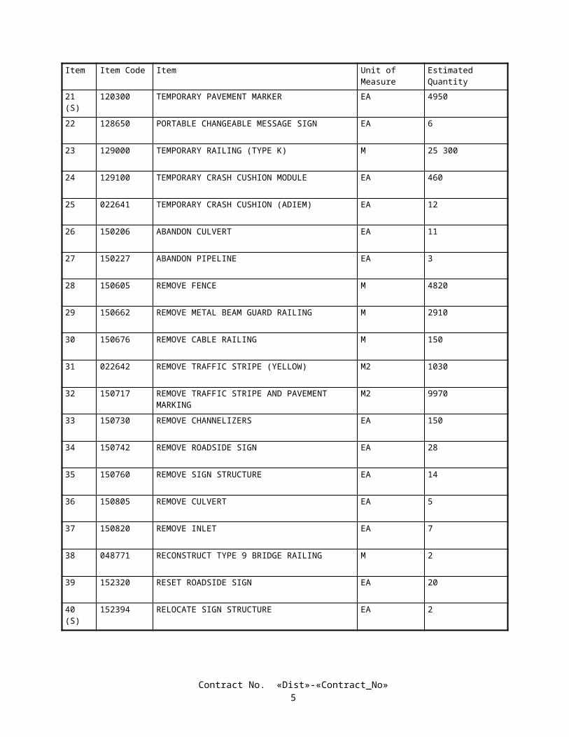
Item Item Code Item Unit of Measure Estimated Quantity
121(S)
048788 3.2 M PERMANENT STEEL CASING M 360
122(S)
048789 3.8 M PERMANENT STEEL CASING M 76
123(S)
048790 1.2 M CAST-IN-DRILLED-HOLE CONCRETE PILING (ROCK SOCKET)
M 202
124(S)
048791 1.5 M CAST-IN-DRILLED-HOLE CONCRETE PILING (ROCK SOCKET)
M 26
125(S)
048792 2.1 M CAST-IN-DRILLED-HOLE CONCRETE PILING (ROCK SOCKET)
M 482
126(S)
048793 2.4 M CAST-IN-DRILLED-HOLE CONCRETE PILING (ROCK SOCKET)
M 141
127(S)
048794 3.0 M CAST-IN-DRILLED-HOLE CONCRETE PILING (ROCK SOCKET)
M 300
128(S)
048795 3.6 M CAST-IN-DRILLED-HOLE CONCRETE PILING (ROCK SOCKET)
M 71
129(S)
500001 PRESTRESSING CAST-IN-PLACE CONCRETE LS LUMP SUM
130(S)
500010 PRESTRESSING LS LUMP SUM
131(F)
510051 STRUCTURAL CONCRETE, BRIDGE FOOTING M3 290
132(F)
510053 STRUCTURAL CONCRETE, BRIDGE M3 29 020
133(F)
510060 STRUCTURAL CONCRETE, RETAINING WALL M3 886
134(F)
048796 RIVER ROCK ARCHITECTURAL TEXTURE M2 12 579
135(F)
022658 STUCCO ARCHITECTURAL TEXTURE M2 228
136(F)
510086 STRUCTURAL CONCRETE, APPROACH SLAB (TYPE N)
M3 876
137(F)
510087 STRUCTURAL CONCRETE, APPROACH SLAB (TYPE R)
M3 20
138(F)
510126 CLASS 2 CONCRETE (MINOR STRUCTURE) M3 42
139(F)
510133 CLASS 2 CONCRETE (RETAINING WALL) M3 14 749
140(F)
510502 MINOR CONCRETE (MINOR STRUCTURE) M3 638
Contract No. «Dist»-«Contract_No»8

Item Item Code Item Unit of Measure Estimated Quantity
141(F)
510800 PAVING NOTCH EXTENSION M3 3
142(F)
511046 HEAVY BLAST TEXTURE M2 110
143(F)
511063 FRACTURED FIN TEXTURE M2 50
144 511106 DRILL AND BOND DOWEL M 67
145(S)
512255 FURNISH PRECAST PRESTRESSED CONCRETE BULB-TEE GIRDER (30 M -35 M)
EA 4
146(S)
512256 FURNISH PRECAST PRESTRESSED CONCRETE BULB-TEE GIRDER (35 M -40 M)
EA 8
147(S)
048799 ERECT PRECAST PRETENSIONED GIRDER EA 12
148 513553 RETAINING WALL (MASONRY WALL) M2 27
149(S)
518050 PTFE BEARING EA 8
150(S)
518051 PTFE SPHERICAL BEARING EA 36
151(S)
519117 JOINT SEAL (MR 30 MM) M 45
152(S)
519120 JOINT SEAL (MR 15 MM) M 46
153(S)
519124 JOINT SEAL ASSEMBLY (MR 60 MM) M 46
154(S)
519125 JOINT SEAL ASSEMBLY (MR 70 MM) M 13
155(S)
519126 JOINT SEAL ASSEMBLY (MR 80 MM) M 24
156(S)
519129 JOINT SEAL ASSEMBLY (MR 101 MM - 160 MM) M 25
157(S)
519130 JOINT SEAL ASSEMBLY (MR 161 MM - 240 MM) M 62
158(S)
519131 JOINT SEAL ASSEMBLY (MR 241 MM - 320 MM) M 12
159(S)
519142 JOINT SEAL (MR 40 MM) M 64
160(S)
519144 JOINT SEAL (MR 50 MM) M 63
Contract No. «Dist»-«Contract_No»9

Item Item Code Item Unit of Measure Estimated Quantity
161(S)
048800 JOINT SEAL (MR 50MM - TYPE B) M 60
162(S-F)
520102 BAR REINFORCING STEEL (BRIDGE) KG 8 991 500
163(S-F)
520103 BAR REINFORCING STEEL (RETAINING WALL) KG 867 487
164(S-F)
550110 COLUMN CASING KG 8700
165(S-F)
048801 ISOLATION CASING KG 232 300
166(F)
560203 FURNISH SIGN STRUCTURE (BRIDGE MOUNTED WITH WALKWAY)
KG 1721
167(S-F)
560204 INSTALL SIGN STRUCTURE (BRIDGE MOUNTED WITH WALKWAY)
KG 1511
168(F)
560208 FURNISH SIGN STRUCTURE (TUBULAR) KG 177 365
169(S-F)
560209 INSTALL SIGN STRUCTURE (TUBULAR) KG 177 365
170(F)
560213 FURNISH SIGN STRUCTURE (LIGHTWEIGHT) KG 5560
171(S-F)
560214 INSTALL SIGN STRUCTURE (LIGHTWEIGHT) KG 5560
172(F)
560218 FURNISH SIGN STRUCTURE (TRUSS) KG 63 178
173(S-F)
560219 INSTALL SIGN STRUCTURE (TRUSS) KG 61 078
174(S)
561008 760 MM CAST-IN-DRILLED-HOLE CONCRETE PILE (SIGN FOUNDATION)
M 50
175(S)
561009 920 MM CAST-IN-DRILLED-HOLE CONCRETE PILE (SIGN FOUNDATION)
M 150
176(S)
561010 1070 MM CAST-IN-DRILLED-HOLE CONCRETE PILE (SIGN FOUNDATION)
M 210
177(S)
561012 1220 MM CAST-IN-DRILLED-HOLE CONCRETE PILE (SIGN FOUNDATION)
M 25
178 562002 METAL (BARRIER MOUNTED SIGN) KG 1120
179 566011 ROADSIDE SIGN - ONE POST EA 78
180 566012 ROADSIDE SIGN - TWO POST EA 14
Contract No. «Dist»-«Contract_No»10

Item Item Code Item Unit of Measure Estimated Quantity
181 568001 INSTALL SIGN (STRAP AND SADDLE BRACKET METHOD)
EA 10
182 597601 PREPARE AND STAIN CONCRETE M2 12 579
183 620909 450 MM ALTERNATIVE PIPE CULVERT M 37
184 620913 600 MM ALTERNATIVE PIPE CULVERT M 6630
185 620919 750 MM ALTERNATIVE PIPE CULVERT M 470
186 620924 900 MM ALTERNATIVE PIPE CULVERT M 78
187 620930 1050 MM ALTERNATIVE PIPE CULVERT M 21
188 022659 300 MM POLYVINYL CHLORIDE PIPE (CL200) M 44
189 022660 400 MM POLYVINYL CHLORIDE PIPE (CL200) M 190
190 022661 1350 MM HIGH DENSITY POLYETHYLENE PIPE (TYPE S)
M 100
191 022662 HIGH DENSITY POLYETHYLENE PIPE LINING GROUT
M3 80
192 650077 750 MM REINFORCED CONCRETE PIPE M 330
193 650084 1200 MM REINFORCED CONCRETE PIPE M 60
194 650576 600 MM REINFORCED CONCRETE PIPE (CLASS V) M 88
195 650578 750 MM REINFORCED CONCRETE PIPE (CLASS V) M 28
196 650582 1050 MM REINFORCED CONCRETE PIPE (CLASS V) M 26
197 650586 1350 MM REINFORCED CONCRETE PIPE (CLASS V) M 43
198 655367 JACKED 600 MM REINFORCED CONCRETE PIPE (CLASS III)
M 20
199 670657 2275 MM STRUCTURAL STEEL PLATE PIPE (3.56 MM THICK)
M 22
200 690267 200 MM BITUMINOUS COATED CORRUGATED STEEL PIPE DOWNDRAIN
M 21
Contract No. «Dist»-«Contract_No»11

Item Item Code Item Unit of Measure Estimated Quantity
201 690271 300 MM BITUMINOUS COATED CORRUGATED STEEL PIPE DOWNDRAIN
M 37
202 690282 600 MM BITUMINOUS COATED CORRUGATED STEEL PIPE DOWNDRAIN (3.51 MM THICK)
M 35
203 690284 750 MM BITUMINOUS COATED CORRUGATED STEEL PIPE DOWNDRAIN (2.01 MM THICK)
M 25
204 690290 1050 MM BITUMINOUS COATED CORRUGATED STEEL PIPE DOWNDRAIN (2.77 MM THICK)
M 12
205 690297 450 MM BITUMINOUS COATED CORRUGATED STEEL PIPE DOWNDRAIN (3.51 MM THICK)
M 56
206 703233 GRATED LINE DRAIN M 750
207 703282 900 MM CORRUGATED STEEL PIPE RISER (1.63 MM THICK)
M 6
208 703587 500 MM WELDED STEEL PIPE (9.53 MM THICK) M 35
209 705568 750 MM HEAVY DUTY AUTOMATIC DRAINAGE GATE
EA 2
210 022663 1200 MM HEAVY DUTY AUTOMATIC DRAINAGE GATE
EA 4
211 705954 300 MM GATE VALVE EA 4
212 022664 400 MM BUTTERFLY VALVE EA 2
213 707470 600 MM PRECAST CONCRETE PIPE RISER M 5
214 707479 900 MM REINFORCED CONCRETE PIPE RISER M 26
215 721008 ROCK SLOPE PROTECTION (LIGHT, METHOD B) M3 53
216 721011 ROCK SLOPE PROTECTION (BACKING NO. 2, METHOD B)
M3 59
217 721022 ROCK SLOPE PROTECTION (1T, METHOD B) M3 230
218 721508 CONCRETED-ROCK SLOPE PROTECTION (LIGHT, METHOD A)
M2 57
219(F)
721810 SLOPE PAVING (CONCRETE) M3 12
220 727905 MINOR CONCRETE (CHANNEL LINING) M3 700
Contract No. «Dist»-«Contract_No»12

Item Item Code Item Unit of Measure Estimated Quantity
221 729010 ROCK SLOPE PROTECTION FABRIC M2 360
222 731502 MINOR CONCRETE (MISCELLANEOUS CONSTRUCTION)
M3 1100
223 022665 MINOR CONCRETE (MISCELLANEOUS CONSTRUCTION) COLORED CONCRETE
M3 730
224 731517 MINOR CONCRETE (GUTTER) M3 180
225 731530 MINOR CONCRETE (TEXTURED PAVING) M2 11 500
226(F)
750001 MISCELLANEOUS IRON AND STEEL KG 29 877
227(S-F)
750496 MISCELLANEOUS METAL (RESTRAINER - PIPE TYPE)
KG 5200
228(S-F)
750498 MISCELLANEOUS METAL (RESTRAINER - CABLE TYPE)
KG 14 530
229(S-F)
750501 MISCELLANEOUS METAL (BRIDGE) KG 700
230(S-F)
750505 BRIDGE DECK DRAINAGE SYSTEM KG 26 220
231(S)
800391 CHAIN LINK FENCE (TYPE CL-1.8) M 6000
232(S)
802590 1.8 M CHAIN LINK GATE (TYPE CL-1.8) EA 33
233(S)
802596 3.7 M CHAIN LINK GATE (TYPE CL-1.8) EA 11
234 820107 DELINEATOR (CLASS 1) EA 300
235 820110 MILEPOST MARKER EA 14
236 820118 GUARD RAILING DELINEATOR EA 170
237(S)
832003 METAL BEAM GUARD RAILING (WOOD POST) M 1420
238(F)
833125 CONCRETE BARRIER (TYPE 25) M 5211
239(F)
833126 CONCRETE BARRIER (TYPE 25A) M 1596
240 833127 CONCRETE BARRIER (TYPE 25B) M 58
Contract No. «Dist»-«Contract_No»13

Item Item Code Item Unit of Measure Estimated Quantity
241(S)
839521 CABLE RAILING M 5700
242(S)
839553 END SECTION EA 28
243(S)
839565 TERMINAL SYSTEM (TYPE SRT) EA 35
244(S)
839568 TERMINAL ANCHOR ASSEMBLY (TYPE SFT) EA 20
245(S)
839569 TERMINAL ANCHOR ASSEMBLY (TYPE CA) EA 10
246(S)
839570 RETURN SECTION EA 10
247(S)
839591 CRASH CUSHION, SAND FILLED EA 6
248(S)
839603 CRASH CUSHION (ADIEM) EA 1
249 839701 CONCRETE BARRIER (TYPE 60) M 6890
250(F)
839702 CONCRETE BARRIER (TYPE 60A) M 518
251 839703 CONCRETE BARRIER (TYPE 60C) M 750
252 839704 CONCRETE BARRIER (TYPE 60D) M 3280
253 839705 CONCRETE BARRIER (TYPE 60E) M 1670
254(S)
840515 THERMOPLASTIC PAVEMENT MARKING M2 570
255(S)
840561 100 MM THERMOPLASTIC TRAFFIC STRIPE M 18 300
256(S)
840563 200 MM THERMOPLASTIC TRAFFIC STRIPE M 5560
257(S)
840564 200 MM THERMOPLASTIC TRAFFIC STRIPE (BROKEN 3.66 M - 0.92 M)
M 4760
258(S)
022666 200 MM THERMOPLASTIC TRAFFIC STRIPE (BROKEN 11.00M-3.5M)
M 350
259(S)
840656 PAINT TRAFFIC STRIPE (2-COAT) M 230 000
260(S)
840666 PAINT PAVEMENT MARKING (2-COAT) M2 12 500
Contract No. «Dist»-«Contract_No»14

Item Item Code Item Unit of Measure Estimated Quantity
261(S)
850101 PAVEMENT MARKER (NON-REFLECTIVE) EA 35 600
262(S)
850111 PAVEMENT MARKER (RETROREFLECTIVE) EA 17 400
263(S)
860251 SIGNAL AND LIGHTING (LOCATION 1) LS LUMP SUM
264(S)
860252 SIGNAL AND LIGHTING (LOCATION 2) LS LUMP SUM
265(S)
860460 LIGHTING AND SIGN ILLUMINATION LS LUMP SUM
266(S)
022667 CHANGEABLE MESSAGE SIGN SYSTEM (LOCATION 1)
LS LUMP SUM
267(S)
022668 CHANGEABLE MESSAGE SIGN SYSTEM (LOCATION 2)
LS LUMP SUM
268(S)
022669 CHANGEABLE MESSAGE SIGN SYSTEM (LOCATION 3)
LS LUMP SUM
269(S)
022670 CHANGEABLE MESSAGE SIGN SYSTEM (LOCATION 4)
LS LUMP SUM
270(S)
022671 IRRIGATION CONTROLLER ENCLOSURE CABINET (TYPE A)
EA 3
271(S)
022672 IRRIGATION CONTROLLER ENCLOSURE CABINET (TYPE B)
EA 3
272(S)
860761 LIGHTING CONDUIT (BRIDGE) M 3190
273(S)
860797 ELECTRIC SERVICE (IRRIGATION) LS LUMP SUM
274(S)
860931 TRAFFIC MONITORING STATION (LOCATION 1) LS LUMP SUM
275(S)
860932 TRAFFIC MONITORING STATION (LOCATION 2) LS LUMP SUM
276(S)
860933 TRAFFIC MONITORING STATION (LOCATION 3) LS LUMP SUM
277(S)
860934 TRAFFIC MONITORING STATION (LOCATION 4) LS LUMP SUM
278(S)
860935 TRAFFIC MONITORING STATION (LOCATION 5) LS LUMP SUM
279(S)
022673 FIBER OPTIC COMMUNICATION SYSTEM LS LUMP SUM
280(S)
861101 RAMP METERING SYSTEM (LOCATION 1) LS LUMP SUM
Contract No. «Dist»-«Contract_No»15
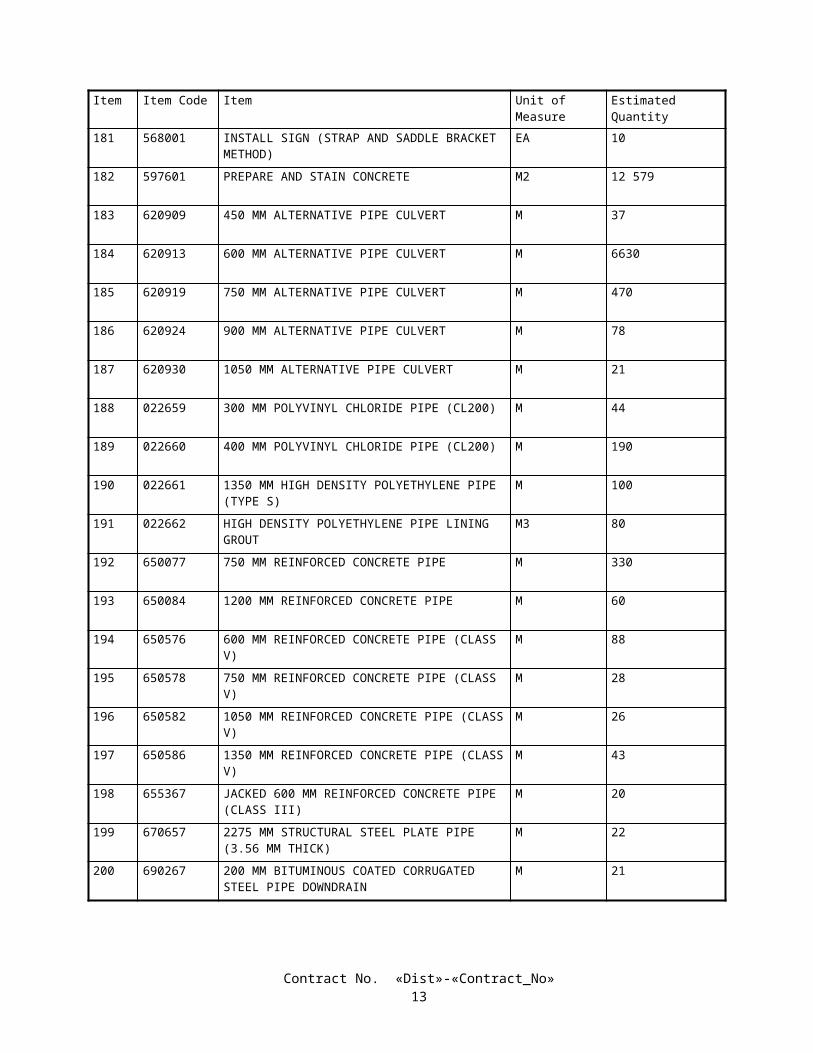
Item Item Code Item Unit of Measure Estimated Quantity
281(S)
861102 RAMP METERING SYSTEM (LOCATION 2) LS LUMP SUM
282(S)
861103 RAMP METERING SYSTEM (LOCATION 3) LS LUMP SUM
283 022674 REMOVE RAMP METERING SYSTEM LS LUMP SUM
284 993013 150 MM FIRE HYDRANT ASSEMBLY EA 1
285 999990 MOBILIZATION LS LUMP SUM
Contract No. «Dist»-«Contract_No»16

STATE OF CALIFORNIA
DEPARTMENT OF TRANSPORTATION
_____________________________
SPECIAL PROVISIONS
Annexed to Contract No. 11-0301U4
SECTION 1. SPECIFICATIONS AND PLANSThe work embraced herein shall conform to the provisions in the Standard Specifications dated July 1999, and the
Standard Plans dated July 1999, of the Department of Transportation insofar as the same may apply, and these special provisions.
Amendments to the Standard Specifications set forth in these special provisions shall be considered as part of the Standard Specifications for the purposes set forth in Section 5-1.04, "Coordination and Interpretation of Plans, Standard Specifications and Special Provisions," of the Standard Specifications. Whenever either the term "Standard Specifications is amended" or the term "Standard Specifications are amended" is used in the special provisions, the indented text or table following the term shall be considered an amendment to the Standard Specifications. In case of conflict between such amendments and the Standard Specifications, the amendments shall take precedence over and be used in lieu of the conflicting portions.
In case of conflict between the Standard Specifications and these special provisions, the special provisions shall take precedence over and shall be used in lieu of the conflicting portions.
SECTION 2. PROPOSAL REQUIREMENTS AND CONDITIONS2-1.01 GENERAL
The bidder's attention is directed to the provisions in Section 2, "Proposal Requirements and Conditions," of the Standard Specifications and these special provisions for the requirements and conditions which the bidder must observe in the preparation of the Proposal form and the submission of the bid.
In addition to the subcontractors required to be listed in conformance with Section 2-1.054, "Required Listing of Proposed Subcontractors," of the Standard Specifications, each proposal shall have listed therein the portion of work that will be performed by each subcontractor listed.
The Bidder's Bond form mentioned in the last paragraph in Section 2-1.07, "Proposal Guaranty," of the Standard Specifications will be found following the signature page of the Proposal.
Submit request for substitution of an "or equal" item, and the data substantiating the request to the Department of Transportation, District 11, Construction Duty Senior MS 73, P.O. Box 85406, San Diego, CA. 92186-5400, so that the request is received by the Department by close of business on the fourth day, not including Saturdays, Sundays and legal holidays, following bid opening.
In conformance with Public Contract Code Section 7106, a Noncollusion Affidavit is included in the Proposal. Signing the Proposal shall also constitute signature of the Noncollusion Affidavit.
The contractor, sub recipient or subcontractor shall not discriminate on the basis of race, color, national origin, or sex in the performance of this contract. The contractor shall carry out applicable requirements of 49 CFR part 26 in the award and administration of DOT-assisted contracts. Failure by the contractor to carry out these requirements is a material breach of this contract, which may result in the termination of this contract or such other remedy as the recipient deems appropriate. Each subcontract signed by the bidder must include this assurance.
2-1.015 FEDERAL LOBBYING RESTRICTIONSSection 1352, Title 31, United States Code prohibits Federal funds from being expended by the recipient or any lower
tier subrecipient of a Federal-aid contract to pay for any person for influencing or attempting to influence a Federal agency or Congress in connection with the awarding of any Federal-aid contract, the making of any Federal grant or loan, or the entering into of any cooperative agreement.
If any funds other than Federal funds have been paid for the same purposes in connection with this Federal-aid contract, the recipient shall submit an executed certification and, if required, submit a completed disclosure form as part of the bid documents.
Contract No. «Dist»-«Contract_No»17

A certification for Federal-aid contracts regarding payment of funds to lobby Congress or a Federal agency is included in the Proposal. Standard Form - LLL, "Disclosure of Lobbying Activities," with instructions for completion of the Standard Form is also included in the Proposal. Signing the Proposal shall constitute signature of the Certification.
The above-referenced certification and disclosure of lobbying activities shall be included in each subcontract and any lower-tier contracts exceeding $100,000. All disclosure forms, but not certifications, shall be forwarded from tier to tier until received by the Engineer.
The Contractor, subcontractors and any lower-tier contractors shall file a disclosure form at the end of each calendar quarter in which there occurs any event that requires disclosure or that materially affects the accuracy of the information contained in any disclosure form previously filed by the Contractor, subcontractors and any lower-tier contractors. An event that materially affects the accuracy of the information reported includes:
A. A cumulative increase of $25,000 or more in the amount paid or expected to be paid for influencing or attempting to influence a covered Federal action; or
B. A change in the person(s) or individual(s) influencing or attempting to influence a covered Federal action; or,C. A change in the officer(s), employee(s), or Member(s) contacted to influence or attempt to influence a covered
Federal action.
2-1.02 DISADVANTAGED BUSINESS ENTERPRISE (DBE)This project is subject to Part 26, Title 49, Code of Federal Regulations entitled "Participation by Disadvantaged
Business Enterprises in Department of Transportation Financial Assistance Programs." The Regulations in their entirety are incorporated herein by this reference.
Bidders shall be fully informed respecting the requirements of the Regulations and the Department's Disadvantaged Business Enterprise (DBE) program developed pursuant to the Regulations; particular attention is directed to the following matters:
A. A DBE must be a small business concern as defined pursuant to Section 3 of U.S. Small Business Act and relevant regulations promulgated pursuant thereto.
B. A DBE may participate as a prime contractor, subcontractor, joint venture partner with a prime or subcontractor, vendor of material or supplies, or as a trucking company.
C. A DBE bidder, not bidding as a joint venture with a non-DBE, will be required to document one or a combination of the following:
1. The bidder will meet the goal by performing work with its own forces.2. The bidder will meet the goal through work performed by DBE subcontractors, suppliers or trucking
companies.3. The bidder, prior to bidding, made adequate good faith efforts to meet the goal.
D. A DBE joint venture partner must be responsible for specific contract items of work, or portions thereof. Responsibility means actually performing, managing and supervising the work with its own forces. The DBE joint venture partner must share in the capital contribution, control, management, risks and profits of the joint venture. The DBE joint venturer must submit the joint venture agreement with the proposal or the DBE Information form required in the Section entitled "Submission of DBE Information" of these special provisions.
E. A DBE must perform a commercially useful function, i.e., must be responsible for the execution of a distinct element of the work and must carry out its responsibility by actually performing, managing and supervising the work.
F. DBEs must be certified by either the California Department of Transportation, or by a participating State of California or local agency which certifies in conformance with Title 49, Code of Federal Regulations, Part 26, as of the date of bid opening. It is the Contractor's responsibility to verify that DBEs are certified. Listings of DBEs certified by the Department are available from the following sources:
1. The Department's DBE Directory, which is published quarterly. This Directory may be obtained from the Department of Transportation, Materiel Operations Branch, Publication Distribution Unit, 1900 Royal Oaks Drive, Sacramento, California 95815, Telephone: (916) 445-3520.
2. The Department's Electronic Information Bulletin Board Service, which is accessible by modem and is updated weekly. The Bulletin Board may be accessed by first contacting the Department's Business Enterprise Program at Telephone: (916) 227-8937 and obtaining a user identification and password.
3. The Department's web site at http://www.dot.ca.gov/hq/bep/index.htm.4. The organizations listed in the Section entitled "DBE Goal for this Project" of these special provisions.
Contract No. «Dist»-«Contract_No»18

G. Credit for materials or supplies purchased from DBEs will be as follows:
1. If the materials or supplies are obtained from a DBE manufacturer, 100 percent of the cost of the materials or supplies will count toward the DBE goal. A DBE manufacturer is a firm that operates or maintains a factory or establishment that produces, on the premises, the materials, supplies, articles, or equipment required under the contract and of the general character described by the specifications.
2. If the materials or supplies are purchased from a DBE regular dealer, 60 percent of the cost of the materials or supplies will count toward the DBE goal. A DBE regular dealer is a firm that owns, operates, or maintains a store, warehouse, or other establishment in which the materials, supplies, articles or equipment of the general character described by the specifications and required under the contract are bought, kept in stock, and regularly sold or leased to the public in the usual course of business. To be a DBE regular dealer, the firm must be an established, regular business that engages, as its principal business and under its own name, in the purchase and sale or lease of the products in question. A person may be a DBE regular dealer in such bulk items as petroleum products, steel, cement, gravel, stone, or asphalt without owning, operating, or maintaining a place of business as provided in this paragraph G.2. if the person both owns and operates distribution equipment for the products. Any supplementing of regular dealers' own distribution equipment shall be by a long-term lease agreement and not on an ad hoc or contract-by-contract basis. Packagers, brokers, manufacturers' representatives, or other persons who arrange or expedite transactions are not DBE regular dealers within the meaning of this paragraph G.2.
3. Credit for materials or supplies purchased from a DBE which is neither a manufacturer nor a regular dealer will be limited to the entire amount of fees or commissions charged for assistance in the procurement of the materials and supplies, or fees or transportation charges for the delivery of materials or supplies required on a job site, provided the fees are reasonable and not excessive as compared with fees charged for similar services.
H. Credit for DBE trucking companies will be as follows:
1. The DBE must be responsible for the management and supervision of the entire trucking operation for which it is responsible on a particular contract, and there cannot be a contrived arrangement for the purpose of meeting the DBE goal.
2. The DBE must itself own and operate at least one fully licensed, insured, and operational truck used on the contract.
3. The DBE receives credit for the total value of the transportation services it provides on the contract using trucks its owns, insures, and operates using drivers it employs.
4. The DBE may lease trucks from another DBE firm, including an owner-operator who is certified as a DBE. The DBE who leases trucks from another DBE receives credit for the total value of the transportation services the lessee DBE provides on the contract.
5. The DBE may also lease trucks from a non-DBE firm, including an owner-operator. The DBE who leases trucks from a non-DBE is entitled to credit only for the fee or commission it receives as a result of the lease arrangement. The DBE does not receive credit for the total value of the transportation services provided by the lessee, since these services are not provided by a DBE.
6. For the purposes of this paragraph H, a lease must indicate that the DBE has exclusive use of and control over the truck. This does not preclude the leased truck from working for others during the term of the lease with the consent of the DBE, so long as the lease gives the DBE absolute priority for use of the leased truck. Leased trucks must display the name and identification number of the DBE.
I. Noncompliance by the Contractor with the requirements of the regulations constitutes a breach of this contract and may result in termination of the contract or other appropriate remedy for a breach of this contract.
J. Bidders are encouraged to use services offered by financial institutions owned and controlled by DBEs.
2-1.02A DBE GOAL FOR THIS PROJECTThe Department has established the following goal for Disadvantaged Business Enterprise (DBE) participation for this
project:
Disadvantaged Business Enterprise (DBE): 20 percent
Bidders may use the services of the following firms to contact interested DBEs. These firms are available to assist DBEs in preparing bids for subcontracting or supplying materials.
Contract No. «Dist»-«Contract_No»19
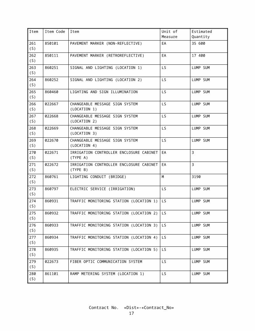
The following firms may be contacted for projects in the following locations:
Districts 04, 05 (except San Luis Obispo and Santa Barbara Counties),06 (except Kern County) and 10: Districts 08, 11 and 12:
Triaxial Management Services, Inc. Triaxial Management Services, Inc.- Oakland - San Diego
2725 Congress Street,1545 Willow Street, 1st Floor Suite 1-DOakland, CA 94607 San Diego, CA 92110Telephone - (510) 286-1313 Telephone - (619) 543-5109FAX No. - (510) 286-6792 FAX No. - (619) 543-5108
Districts 07 and 08; in San Luis Obispo and Santa Barbara Countiesin District 05; and in Kern County in District 06: Districts 01, 02, 03 and 09:
Triaxial Management Services, Inc. Triaxial Management Services, Inc.- Los Angeles - Sacramento2594 Industry Way, Suite 101 930 Alhambra Blvd., #205Lynwood, CA 90262 Sacramento, CA 95816Telephone - (310) 537-6677 Telephone - (916) 553-4172FAX No. - (310) 637-0128 FAX No. - (916) 553-4173
2-1.02B SUBMISSION OF DBE INFORMATIONThe required DBE information shall be submitted on the "CALTRANS BIDDER - DBE INFORMATION" form
included in the Proposal. If the DBE information is not submitted with the bid, the DBE Information form shall be removed from the documents prior to submitting the bid.
It is the bidder's responsibility to make enough work available to DBEs and to select those portions of the work or material needs consistent with the available DBEs to meet the goal for DBE participation or to provide information to establish that, prior to bidding, the bidder made adequate good faith efforts to do so.
If DBE information is not submitted with the bid, the apparent successful bidder (low bidder), the second low bidder and the third low bidder shall submit DBE information to the Department of Transportation, 1120 N Street, Room 0200, MS #26, Sacramento, California 95814 so the information is received by the Department no later than 4:00 p.m. on the fourth day, not including Saturdays, Sundays and legal holidays, following bid opening. DBE information sent by U.S. Postal Service certified mail with return receipt and certificate of mailing and mailed on or before the third day, not including Saturdays, Sundays and legal holidays, following bid opening will be accepted even if it is received after the fourth day following bid opening. Failure to submit the required DBE information by the time specified will be grounds for finding the bid or proposal nonresponsive. Other bidders need not submit DBE information unless requested to do so by the Department.
The bidder's DBE information shall establish that good faith efforts to meet the DBE goal have been made. To establish good faith efforts, the bidder shall demonstrate that the goal will be met or that, prior to bidding, adequate good faith efforts to meet the goal were made.
Bidders are cautioned that even though their submittal indicates they will meet the stated DBE goal, their submittal should also include their adequate good faith efforts information along with their DBE goal information to protect their eligibility for award of the contract in the event the Department, in its review, finds that the goal has not been met.
The bidder's DBE information shall include the names, addresses and phone numbers of DBE firms that will participate, with a complete description of work or supplies to be provided by each, the dollar value of each DBE transaction, and a written confirmation from the DBE that it is participating in the contract. A copy of the DBE's quote will serve as written confirmation that the DBE is participating in the contract. When 100 percent of a contract item of work is not to be performed or furnished by a DBE, a description of the exact portion of that work to be performed or furnished by that DBE shall be included in the DBE information, including the planned location of that work. The work that a DBE prime contractor has committed to performing with its own forces as well as the work that it has committed to be performed by DBE subcontractors, suppliers and trucking companies will count toward the goal.
Contract No. «Dist»-«Contract_No»20

The information necessary to establish the bidder's adequate good faith efforts to meet the DBE goal should include:
A. The names and dates of each publication in which a request for DBE participation for this project was placed by the bidder.
B. The names and dates of written notices sent to certified DBEs soliciting bids for this project and the dates and methods used for following up initial solicitations to determine with certainty whether the DBEs were interested.
C. The items of work which the bidder made available to DBE firms, including, where appropriate, any breaking down of the contract work items (including those items normally performed by the bidder with its own forces) into economically feasible units to facilitate DBE participation. It is the bidder's responsibility to demonstrate that sufficient work to meet the DBE goal was made available to DBE firms.
D. The names, addresses and phone numbers of rejected DBE firms, the firms selected for that work, and the reasons for the bidder's choice.
E. Efforts made to assist interested DBEs in obtaining bonding, lines of credit or insurance, and any technical assistance or information related to the plans, specifications and requirements for the work which was provided to DBEs.
F. Efforts made to assist interested DBEs in obtaining necessary equipment, supplies, materials, or related assistance or services, excluding supplies and equipment the DBE subcontractor purchases or leases from the prime contractor or its affiliate.
G. The names of agencies contacted to provide assistance in contacting, recruiting and using DBE firms.H. Any additional data to support a demonstration of good faith efforts.
2-1.03 ESCROW OF BID DOCUMENTATIONBid documentation shall consist of all documentary and calculated information generated by the Contractor in
preparation of the bid. The bid documentation shall conform to the requirements in these special provisions, and shall be submitted to the Department and held in escrow for the duration of the contract.
In the resolution of disputes involving the project, the escrowed bid documents will be the only documents accepted from the Contractor regarding preparation of the bid.
In signing the proposal, the bidder certifies that the material submitted for escrow constitutes all the documentary information used in preparation of the bid and that he has personally examined the contents of the container and that they are complete.
The bidder shall include with the proposal, the identification of the bidder's representative authorized to present the bid documentation and the persons responsible for preparing the bidder's estimate.
Nothing in the bid documentation shall be construed to change or modify the terms or conditions of the contract.Escrowed bid documentation will not be used for pre-award evaluation of the Contractor's anticipated methods of
construction, nor to assess the Contractor's qualifications for performing the work.Bid documentation shall clearly itemize the Contractor's estimated costs of performing the work. The documentation
submitted shall be complete and so detailed as to allow for an in-depth analysis of the Contractor's estimate.The bid documentation shall include, but not be limited to: quantity takeoffs; rate schedules for the direct costs and the
time- and nontime-related indirect costs for labor (by craft), plant and equipment ownership and operation, permanent and expendable materials, insurance and subcontracted work; estimated construction schedules, including sequence and duration and development of production rates; quotations from subcontractors and suppliers; estimates of field and home office overhead; contingency and margin for each contract item of work; and other reports, calculations and information used by the bidder to arrive at the estimate submitted with the proposal.
The Contractor shall also submit bid documentation for each subcontractor whose total subcontract exceeds $250,000. Subcontractor bid documentation shall be enclosed with the Contractor's submittal. The examination of subcontractors' bid documentation will be accomplished in the same manner as for the Contractor's bid documentation. If a subcontractor is replaced, bid documentation for the new subcontractor shall be submitted for review and escrow before authorization for the substitution will be granted. Upon request of a subcontractor, the bid documentation from that subcontractor shall be reviewed only by the subcontractor and the Department.
If the bidder is a joint venture, the bid documentation shall include the joint venture agreement, the joint venture estimate comparison and final reconciliation of the joint venture estimate.
Copies of the proposals submitted by the first, second and third low bidders will be provided to the respective bidders for inclusion in the bid documentation to be escrowed.
The first, second, and third apparent low bidders shall present the bid documentation for escrow at the District 11 Office, 2829 Juan Street, San Diego 92110, CA, on the first Wednesday, at 10:00 a.m., following the time indicated in the "Notice to Contractors" for the opening of bids.
Bid documentation shall be submitted in a sealed container, clearly marked with the bidder's name, date of submittal, project contract number and the words, "Bid Documentation for Escrow."
Contract No. «Dist»-«Contract_No»21

Failure to submit the actual and complete bid documentation as specified herein within the time specified shall be cause for rejection of the proposal.
Upon submittal, the bid documentation of the apparent low bidder will be examined and inventoried by the duly designated representatives of the Contractor and the Department to ensure that the bid documentation is authentic, legible, and in accordance with the terms of this section "Escrow of Bid Documentation." The examination will not include review of, nor will it constitute approval of, proposed construction methods, estimating assumptions or interpretation of the contract. The examination will not alter any conditions or terms of the contract. The acceptance or rejection by the Department that the submitted bid documents are in compliance with this section "Escrow of Bid Documentation" shall be completed within 48 hours of the time the bid documentation is submitted by the Contractor.
At the completion of the examination, the bid documents will be sealed and jointly deposited at an agreed commercial bank.
Bid documentation submitted by the second and third apparent low bidders will be jointly deposited at agreed commercial banks. If the apparent low bid is withdrawn or rejected, the bid documentation of the second low bidder will be examined and inventoried in the manner specified above, then sealed and deposited again in escrow. If the second low bid is withdrawn or rejected, the bid documentation of the third low bidder will be examined and inventoried in the manner specified above, then sealed and deposited again in escrow. Upon execution and final approval of the contract or rejection of all bids, the bid documentation will be returned to any remaining unsuccessful bidders.
The escrowed bid documentation may be examined by the designated representatives of both the Department and the Contractor, at any time deemed necessary by either the Department or the Contractor to assist in the negotiation of price adjustments and change orders, or in the settlement of claims or disputes.
If requested by a Disputes Review Board, the escrowed bid documentation may be utilized to assist the Board in its recommendations.
The bid documentation submitted by the Contractor will be held in escrow until the contract has been completed, the ultimate resolution of all disputes and claims has been achieved and receipt of final payment has been accepted by the Contractor. The escrowed bid documentation will then be released from escrow to the Contractor.
The bid documentation submitted by the bidder is, and shall remain, the property of the bidder, and is subject to only joint review by the Department and the bidder. The Department stipulates and expressly acknowledges that the submitted bid documentation constitutes trade secrets and will not be deemed public records. This acknowledgment is based on the Department's express understanding that the information contained in the bid documentation is not known outside the bidder's business, is known only to a limited extent and only by a limited number of employees of the bidder, is safeguarded while in the bidder's possession, is extremely valuable to the bidder and could be extremely valuable to the bidder's competitors by virtue of it reflecting the bidder's contemplated techniques of construction. The Department acknowledges that the bid documentation includes a compilation of information used in the bidder's business, intended to give the bidder an opportunity to obtain an advantage over competitors who do not know of or use the contents of the documentation. The Department agrees to safeguard the bid documentation, and all information contained therein, against disclosure, including disclosure of subcontractor bid documentation to the Contractor and other subcontractors to the fullest extent permitted by law. However, in the event of arbitration or litigation, the bid documentation shall be subject to discovery, and the Department assumes no responsibility for safeguarding the bid documentation unless the Contractor has obtained an appropriate protective order issued by the arbitrator or the court.
Full compensation for preparing the bid documentation, presenting it for escrow and reviewing it for escrow and upon request of the Engineer shall be considered as included in the contract prices paid for the various items of work, and no additional compensation will be allowed therefor.
The direct cost of depositing the bid documentation in escrow at the agreed commercial bank will be paid by the State.
SECTION 3. AWARD AND EXECUTION OF CONTRACTThe bidder's attention is directed to the provisions in Section 3, "Award and Execution of Contract," of the Standard
Specifications and these special provisions for the requirements and conditions concerning award and execution of contract.The award of the contract, if it be awarded, will be to the lowest responsible bidder whose proposal complies with all the
requirements prescribed and who has met the goal for DBE participation or has demonstrated, to the satisfaction of the Department, adequate good faith efforts to do so. Meeting the goal for DBE participation or demonstrating, to the satisfaction of the Department, adequate good faith efforts to do so is a condition for being eligible for award of contract.
A "Payee Data Record" form will be included in the contract documents to be executed by the successful bidder. The purpose of the form is to facilitate the collection of taxpayer identification data. The form shall be completed and returned to the Department by the successful bidder with the executed contract and contract bonds. For the purposes of the form, payee shall be deemed to mean the successful bidder. The form is not to be completed for subcontractors or suppliers. Failure to complete and return the "Payee Data Record" form to the Department as provided herein will result in the retention of 31 percent of payments due the contractor and penalties of up to $20,000. This retention of payments for failure to complete the "Payee Data Record" form is in addition to any other retention of payments due the Contractor.
Contract No. «Dist»-«Contract_No»22

SECTION 4. BEGINNING OF WORK, TIME OF COMPLETION AND LIQUIDATED DAMAGESAttention is directed to the provisions in Sections 8-1.03, "Beginning of Work," 8-1.06, "Time of Completion," 8-1.07,
"Liquidated Damages," and 20-4.08, "Plant Establishment Work," of the Standard Specifications and these special provisions.
The Contractor shall begin work within 15 calendar days after the contract has been approved by the Attorney General or the attorney appointed and authorized to represent the Department of Transportation.
The work (except plant establishment work) shall be diligently prosecuted to completion before the expiration of 1100 WORKING DAYS beginning on the fifteenth calendar day after approval of the contract.
The Contractor shall pay to the State of California the sum of $ 25,000 per day, for each and every calendar day's delay in finishing the work (except plant establishment work) in excess of the number of working days prescribed above.
The Contractor shall diligently prosecute all work (including plant establishment) to completion before the expiration of 1850 WORKING DAYS beginning on the fifteenth calendar day after approval of the contract.
The Contractor shall pay to the State of California the sum of $250 per day, for each and every calendar day's delay in completing the work in excess of the number of working days prescribed above.
In no case will liquidated damages of more than $ 25,000 per day be assessed.It is anticipated that water will be available in sufficient quantities for the prosecution of the work. However, water
shortages may occur during the life of the contract. Arrangements or commitments obtained by the Department are not a part of the contract. It is expressly understood and agreed that the Department assumes no responsibility to the bidder or Contractor whatsoever in respect to the arrangements made with source. The Contractor shall assume all risks in connection with the use of the source and the terms upon which the use shall be made. There is no warranty or guaranty, either expressed or implied, to the quantity of water that can be obtained from the source. If the Department has compiled "Materials Information", as referred to in "Watering" of these special provisions, the bidder or Contractor is cautioned to make independent investigations and obtain the commitments or allocations as the bidder or Contractor deems necessary to verify the quantity of water available. The Contractor shall, at the Contractor's expense, make arrangements or obtain commitments or allocations necessary to provide water for the project.
During the progress of the work, if water becomes unavailable or unavailable in the quantities needed for prosecution of the work, the unavailability of water will be considered a "shortage of materials" in conformance with the provisions in Section 8-1.07, "Liquidated Damages," of the Standard Specifications except for compensation. The Contractor will be granted an extension of time and will not be assessed with liquidated damages for any portion of the delay in completion of the work beyond the time shown above for the completion of the work caused by the unavailability of water, provided the Contractor notifies the Engineer and furnishes proof of the "shortage of materials" as required in the third and fourth paragraphs in Section 8-1.07, "Liquidated Damages," of the Standard Specifications. If the Contractor sustains delay costs or damages which could not have been avoided by the judicious handling of forces, equipment and plant, there shall be paid to the Contractor the amount the Engineer may find to be a fair and reasonable compensation for the part of the Contractor's actual loss, as, in the opinion of the Engineer, was unavoidable, determined in the same manner as provided for right of way delays in Section 8-1.09, "Right of Way Delays," of the Standard Specifications. The Contractor shall be entitled to no other compensation for such delay. The provisions in Section 5-1.116, "Differing Site Conditions," of the Standard Specifications shall not apply to the unavailability of water.
The time limit specified for the completion of the work contemplated herein is considered insufficient to permit completion of the work by the Contractor working a normal number of hours per day or week on a single shift basis. Should the Contractor fail to maintain the progress of the work in conformance with "Progress Schedule (Critical Path Method)" of these special provisions, additional shifts will be required to the extent necessary to ensure that the progress conforms to the above mentioned schedule and that the work will be completed within the time limit specified.
Full compensation for any additional costs occasioned by compliance with the provisions in this section shall be considered as included in the prices paid for the various contract items of work and no additional compensation will be allowed therefor.
SECTION 5. GENERALSECTION 5-1. MISCELLANEOUS
5-1.01 PLANS AND WORKING DRAWINGSWhen the specifications require working drawings to be submitted to the Division of Structure Design, the drawings
shall be submitted to: Division of Structure Design, Documents Unit, Mail Station 9, 1801 30th Street, Sacramento, CA 95816, Telephone (916) 227-8252.
Contract No. «Dist»-«Contract_No»23

5-1.011 EXAMINATION OF PLANS, SPECIFICATIONS, CONTRACT, AND SITE OF WORKThe second paragraph of Section 2-1.03, "Examination of Plans, Specifications, Contract, and Site of Work," of the
Standard Specifications is amended to read:
• Where the Department has made investigations of site conditions, including subsurface conditions in areas where work is to be performed under the contract, or in other areas, some of which may constitute possible local material sources, bidders or Contractors may, upon written request, inspect the records of the Department as to those investigations subject to and upon the conditions hereinafter set forth.
Attention is directed to "Differing Site Conditions" of these special provisions regarding physical conditions at the site which may differ from those indicated in "Materials Information," log of test borings or other geotechnical information obtained by the Department's investigation of site conditions.
5-1.012 DIFFERING SITE CONDITIONSAttention is directed to Section 5-1.116, "Differing Site Conditions," of the Standard Specifications.During the progress of the work, if subsurface or latent conditions are encountered at the site differing materially from
those indicated in the "Materials Information," log of test borings, other geotechnical data obtained by the Department's investigation of subsurface conditions, or an examination of the conditions above ground at the site, the party discovering those conditions shall promptly notify the other party in writing of the specific differing conditions before they are disturbed and before the affected work is performed.
The Contractor will be allowed 15 days from the notification of the Engineer's determination of whether or not an adjustment of the contract is warranted, in which to file a notice of potential claim in conformance with the provisions of Section 9-1.04, "Notice of Potential Claim," of the Standard Specifications and as specified herein; otherwise the decision of the Engineer shall be deemed to have been accepted by the Contractor as correct. The notice of potential claim shall set forth in what respects the Contractor's position differs from the Engineer's determination and provide any additional information obtained by the Contractor, including but not limited to additional geotechnical data. The notice of potential claim shall be accompanied by the Contractor's certification that the following were made in preparation of the bid: a review of the contract, a review of the "Materials Information," a review of the log of test borings and other records of geotechnical data to the extent they were made available to bidders prior to the opening of bids, and an examination of the conditions above ground at the site. Supplementary information, obtained by the Contractor subsequent to the filing of the notice of potential claim, shall be submitted to the Engineer in an expeditious manner.
5-1.015 LABORATORYWhen a reference is made in the specifications to the "Laboratory," the reference shall mean the Division of Materials
Engineering and Testing Services and the Division of Structural Foundations of the Department of Transportation, or established laboratories of the various Districts of the Department, or other laboratories authorized by the Department to test materials and work involved in the contract. When a reference is made in the specifications to the "Transportation Laboratory," the reference shall mean the Division of Materials Engineering and Testing Services and the Division of Structural Foundations, located at 5900 Folsom Boulevard, Sacramento, CA 95819, Telephone (916) 227-7000.
5-1.017 CONTRACT BONDSAttention is directed to Section 3-1.02, "Contract Bonds," of the Standard Specifications and these special provisions.The payment bond shall be in a sum not less than one hundred percent of the total amount payable by the terms of the
contract.
5-1.018 EXCAVATION SAFETY PLANSSection 5-1.02A, "Trench Excavation Safety Plans," of the Standard Specifications is amended to read:
5-1.02A Excavation Safety Plans• The Construction Safety Orders of the Division of Occupational Safety and Health shall apply to all excavations. For all excavations 1.5 m or more in depth, the Contractor shall submit to the Engineer a detailed plan showing the design and details of the protective systems to be provided for worker protection from the hazard of caving ground during excavation. The detailed plan shall include any tabulated data and any design calculations used in the preparation of the plan. Excavation shall not begin until the detailed plan has been reviewed and approved by the Engineer.• Detailed plans of protective systems for which the Construction Safety Orders require design by a registered professional engineer shall be prepared and signed by an engineer who is registered as a Civil Engineer in the State
Contract No. «Dist»-«Contract_No»24

of California, and shall include the soil classification, soil properties, soil design calculations that demonstrate adequate stability of the protective system, and any other design calculations used in the preparation of the plan.• No plan shall allow the use of a protective system less effective than that required by the Construction Safety Orders.• If the detailed plan includes designs of protective systems developed only from the allowable configurations and slopes, or Appendices, contained in the Construction Safety Orders, the plan shall be submitted at least 5 days before the Contractor intends to begin excavation. If the detailed plan includes designs of protective systems developed from tabulated data, or designs for which design by a registered professional engineer is required, the plan shall be submitted at least 3 weeks before the Contractor intends to begin excavation.• Attention is directed to Section 7-1.01E, "Trench Safety."
The third paragraph of Section 19-1.02, "Preservation of Property," of the Standard Specifications is amended to read:
• In addition to the provisions in Sections 5-1.02, "Plans and Working Drawings," and 5-1.02A, "Excavation Safety Plans," detailed plans of the protective systems for excavations on or affecting railroad property will be reviewed for adequacy of protection provided for railroad facilities, property, and traffic. These plans shall be submitted at least 9 weeks before the Contractor intends to begin excavation requiring the protective systems. Approval by the Engineer of the detailed plans for the protective systems will be contingent upon the plans being satisfactory to the railroad company involved.
5-1.019 COST REDUCTION INCENTIVEAttention is directed to Section 5-1.14, "Cost Reduction Incentive," of the Standard Specifications.Prior to preparing a cost reduction proposal, the Contractor shall request a meeting with the Engineer to discuss the
proposal in concept and to determine the merit of the cost reduction proposal. Items of discussion will also include permit issues, impact on other projects, impact on the project schedule, peer reviews, and review times required by the Department and other agencies.
5-1.02 LABOR NONDISCRIMINATIONAttention is directed to the following Notice that is required by Chapter 5 of Division 4 of Title 2, California Code of
Regulations.
NOTICE OF REQUIREMENT FOR NONDISCRIMINATION PROGRAM
(GOV. CODE, SECTION 12990)Your attention is called to the "Nondiscrimination Clause", set forth in Section 7-1.01A(4), "Labor Nondiscrimination," of the Standard Specifications, which is applicable to all nonexempt State contracts and subcontracts, and to the "Standard California Nondiscrimination Construction Contract Specifications" set forth therein. The specifications are applicable to all nonexempt State construction contracts and subcontracts of $5000 or more.
5-1.03 INTEREST ON PAYMENTSInterest shall be payable on progress payments, payments after acceptance, final payments, extra work payments, and
claim payments as follows:
A. Unpaid progress payments, payment after acceptance, and final payments shall begin to accrue interest 30 days after the Engineer prepares the payment estimate.
B. Unpaid extra work bills shall begin to accrue interest 30 days after preparation of the first pay estimate following receipt of a properly submitted and undisputed extra work bill. To be properly submitted, the bill must be submitted within 7 days of the performance of the extra work and in conformance with the provisions in Section 9 -1.03C, "Records," and Section 9-1.06, "Partial Payments," of the Standard Specifications. An undisputed extra work bill not submitted within 7 days of performance of the extra work will begin to accrue interest 30 days after the preparation of the second pay estimate following submittal of the bill.
C. The rate of interest payable for unpaid progress payments, payments after acceptance, final payments, and extra work payments shall be 10 percent per annum.
D. The rate of interest payable on a claim, protest or dispute ultimately allowed under this contract shall be 6 percent per annum. Interest shall begin to accrue 61 days after the Contractor submits to the Engineer information in sufficient detail to enable the Engineer to ascertain the basis and amount of said claim, protest or dispute.
Contract No. «Dist»-«Contract_No»25

The rate of interest payable on any award in arbitration shall be 6 percent per annum if allowed under the provisions of Civil Code Section 3289.
5-1.031 FINAL PAYMENT AND CLAIMSAttention is directed to Section 9-1.07B, "Final Payment and Claims," of the Standard Specifications.If the Contractor files a timely written statement of claims in response to the proposed final estimate, the District that
administers the contract will submit a claim position letter to the Contractor by hand delivery or deposit in the U.S. mail within 135 days of acceptance of the contract. The claim position letter will delineate the District's position on the Contractor's claims. If the Contractor disagrees with the claim position letter, the Contractor shall submit a written notification of its disagreement to be received by the District not later than 15 days after the Contractor's receipt of the claim position letter. The written notification of disagreement shall set forth the basis for the Contractor's disagreement and be submitted to the office designated in the claim position letter. The Contractor's failure to provide a timely, written notification of disagreement shall constitute the Contractor's acceptance and agreement with the determinations provided in the claim position letter and with final payment pursuant to the claim position letter.
If the Contractor files a timely notification of disagreement with the District claim position letter, the board of review designated by the District Director to review claims that remain in dispute will meet with the Contractor within 45 days after receipt by the District of the notification of disagreement. Attendance by the Contractor at the board of review meeting shall be mandatory.
If the District fails to submit a claim position letter to the Contractor within 135 days after the acceptance of the contract and the Contractor has claims that remain in dispute, the Contractor may request a meeting with the board of review designated by the District Director to review claims that remain in dispute. The Contractor's request for a meeting shall identify the claims that remain in dispute. If the Contractor files a request for a meeting, the board of review will meet with the Contractor within 45 days after the District receives the request for the meeting. Attendance by the Contractor at the District Director's board of review meeting shall be mandatory.
Failure of the Contractor to file a timely written statement of claims in response to the proposed final estimate, or to file a timely notification of disagreement with the District claim position letter, or to attend the District Director's board of review meeting shall constitute a failure to pursue diligently and exhaust the administrative procedures in the contract and shall be a bar to arbitration in conformance with the requirements in Section 10240.2 of the California Public Contract Code.
5-1.04 PUBLIC SAFETYThe Contractor shall provide for the safety of traffic and the public in conformance with the provisions in Section 7 -1.09,
"Public Safety," of the Standard Specifications and these special provisions.The Contractor shall install temporary railing (Type K) between a lane open to public traffic and an excavation, obstacle
or storage area when the following conditions exist:
A. Excavations.—The near edge of the excavation is 3.6 m or less from the edge of the lane, except:
1. Excavations covered with sheet steel or concrete covers of adequate thickness to prevent accidental entry by traffic or the public.
2. Excavations less than 0.3-m deep.3. Trenches less than 0.3-m wide for irrigation pipe or electrical conduit, or excavations less than 0.3-m in
diameter.4. Excavations parallel to the lane for the purpose of pavement widening or reconstruction.5. Excavations in side slopes, where the slope is steeper than 1:4 (vertical:horizontal).6. Excavations protected by existing barrier or railing.
B. Temporarily Unprotected Permanent Obstacles.—The work includes the installation of a fixed obstacle together with a protective system, such as a sign structure together with protective railing, and the Contractor elects to install the obstacle prior to installing the protective system; or the Contractor, for the Contractor's convenience and with permission of the Engineer, removes a portion of an existing protective railing at an obstacle and does not replace such railing complete in place during the same day.
C. Storage Areas.—Material or equipment is stored within 3.6 m of the lane and the storage is not otherwise prohibited by the provisions of the Standard Specifications and these special provisions.
The approach end of temporary railing (Type K), installed in conformance with the provisions in this section "Public Safety" and in Section 7-1.09, "Public Safety," of the Standard Specifications, shall be offset a minimum of 4.6 m from the edge of the traffic lane open to public traffic. The temporary railing shall be installed on a skew toward the edge of the traffic lane of not more than 0.3-m transversely to 3 m longitudinally with respect to the edge of the traffic lane. If the 4.6 -m
Contract No. «Dist»-«Contract_No»26

minimum offset cannot be achieved, the temporary railing shall be installed on the 10 to 1 skew to obtain the maximum available offset between the approach end of the railing and the edge of the traffic lane, and an array of temporary crash cushion modules shall be installed at the approach end of the temporary railing.
Temporary railing (Type K) shall conform to the provisions in Section 12-3.08, "Temporary Railing (Type K)," of the Standard Specifications. Temporary railing (Type K), conforming to the details shown on 1999 Standard Plan T3, may be used. Temporary railing (Type K) fabricated prior to January 1, 1993, and conforming to 1988 Standard Plan B11-30 may be used, provided the fabrication date is printed on the required Certificate of Compliance.
Temporary crash cushion modules shall conform to the provisions in "Temporary Crash Cushion Module" of these special provisions.
Except for installing, maintaining and removing traffic control devices, whenever work is performed or equipment is operated in the following work areas, the Contractor shall close the adjacent traffic lane unless otherwise provided in the Standard Specifications and these special provisions:
Approach Speed of Public Traffic (Posted Limit) (Kilometers Per Hour)
Work Areas
Over 72 (45 Miles Per Hour) Within 1.8 m of a traffic lane but not on a traffic lane56 to 72 (35 to 45 Miles Per Hour) Within 0.9-m of a traffic lane but not on a traffic lane
The lane closure provisions of this section shall not apply if the work area is protected by permanent or temporary railing or barrier.
When traffic cones or delineators are used to delineate a temporary edge of a traffic lane, the line of cones or delineators shall be considered to be the edge of the traffic lane, however, the Contractor shall not reduce the width of an existing lane to less than 3 m without written approval from the Engineer.
When work is not in progress on a trench or other excavation that required closure of an adjacent lane, the traffic cones or portable delineators used for the lane closure shall be placed off of and adjacent to the edge of the traveled way. The spacing of the cones or delineators shall be not more than the spacing used for the lane closure.
Suspended loads or equipment shall not be moved nor positioned over public traffic or pedestrians.Full compensation for conforming to the provisions in this section "Public Safety," including furnishing and installing
temporary railing (Type K) and temporary crash cushion modules, shall be considered as included in the contract prices paid for the various items of work involved and no additional compensation will be allowed therefor.
5-1.05 SURFACE MINING AND RECLAMATION ACTAttention is directed to the Surface Mining and Reclamation Act of 1975, commencing in Public Resources Code,
Mining and Geology, Section 2710, which establishes regulations pertinent to surface mining operations, and to California Public Contract Code Section 10295.5.
Material from mining operations furnished for this project shall only come from permitted sites in compliance with California Public Contract Code Section 10295.5.
The requirements of this section shall apply to materials furnished for the project, except for acquisition of materials in conformance with the provisions in Section 4-1.05, "Use of Materials Found on the Work," of the Standard Specifications.
5-1.06 REMOVAL OF ASBESTOS AND HAZARDOUS SUBSTANCESWhen the presence of asbestos or hazardous substances are not shown on the plans or indicated in the specifications and
the Contractor encounters materials which the Contractor reasonably believes to be asbestos or a hazardous substance as defined in Section 25914.1 of the Health and Safety Code, and the asbestos or hazardous substance has not been rendered harmless, the Contractor may continue work in unaffected areas reasonably believed to be safe. The Contractor shall immediately cease work in the affected area and report the condition to the Engineer in writing.
In conformance with Section 25914.1 of the Health and Safety Code, removal of asbestos or hazardous substances including exploratory work to identify and determine the extent of the asbestos or hazardous substance will be performed by separate contract.
If delay of work in the area delays the current controlling operation, the delay will be considered a right of way delay and the Contractor will be compensated for the delay in conformance with the provisions in Section 8-1.09, "Right of Way Delays," of the Standard Specifications.
5-1.07 YEAR 2000 COMPLIANCEThis contract is subject to Year 2000 Compliance for automated devices in the State of California.Year 2000 compliance for automated devices in the State of California is achieved when embedded functions have or
create no logical or mathematical inconsistencies when dealing with dates prior to and beyond 1999. The year 2000 is
Contract No. «Dist»-«Contract_No»27

recognized and processed as a leap year. The product shall operate accurately in the manner in which the product was intended for date operation without requiring manual intervention.
The Contractor shall provide the Engineer a Certificate of Compliance from the manufacturer in conformance with the provisions in Section 6-1.07, "Certificates of Compliance," of the Standard Specifications for all automated devices furnished for the project.
5-1.075 BUY AMERICA REQUIREMENTSAttention is directed to the "Buy America" requirements of the Surface Transportation Assistance Act of 1982 (Section
165) and the Intermodal Surface Transportation Efficiency Act of 1991 (ISTEA) Sections 1041(a) and 1048(a), and the regulations adopted pursuant thereto. In conformance with the law and regulations, all manufacturing processes for steel and iron materials furnished for incorporation into the work on this project shall occur in the United States; with the exception that pig iron and processed, pelletized and reduced iron ore manufactured outside of the United States may be used in the domestic manufacturing process for such steel and iron materials. The application of coatings, such as epoxy coating, galvanizing, painting, and other coatings that protect or enhance the value of steel or iron materials shall be considered a manufacturing process subject to the "Buy America" requirements.
A Certificate of Compliance conforming to the provisions in Section 6-1.07, "Certificates of Compliance," of the Standard Specifications shall be furnished for steel and iron materials. The certificates, in addition to certifying that the materials comply with the specifications, shall specifically certify that all manufacturing processes for the materials occurred in the United States, except for the above exceptions.
The requirements imposed by the law and regulations do not prevent a minimal use of foreign steel and iron materials if the total combined cost of the materials used does not exceed one-tenth of one percent (0.1 percent) of the total contract cost or $2500, whichever is greater. The Contractor shall furnish the Engineer acceptable documentation of the quantity and value of the foreign steel and iron prior to incorporating the materials into the work.
5-1.08 SUBCONTRACTOR AND DBE RECORDSThe Contractor shall maintain records showing the name and business address of each first-tier subcontractor. The
records shall also show the name and business address of every DBE subcontractor, DBE vendor of materials and DBE trucking company, regardless of tier. The records shall show the date of payment and the total dollar figure paid to all of these firms. DBE prime contractors shall also show the date of work performed by their own forces along with the corresponding dollar value of the work.
Upon completion of the contract, a summary of these records shall be prepared on Form CEM-2402 (F) and certified correct by the Contractor or the Contractor's authorized representative, and shall be furnished to the Engineer. The form shall be furnished to the Engineer within 90 days from the date of contract acceptance. $10,000 will be withheld from payment until the Form CEM-2402 (F) is submitted. The amount will be returned to the Contractor when a satisfactory Form CEM-2402 (F) is submitted.
Prior to the fifteenth of each month, the Contractor shall submit documentation to the Engineer showing the amount paid to DBE trucking companies listed in the Contractor's DBE information. This monthly documentation shall indicate the portion of the revenue paid to DBE trucking companies which is claimed toward DBE participation. The Contractor shall also obtain and submit documentation to the Engineer showing the amount paid by DBE trucking companies to all firms, including owner-operators, for the leasing of trucks. The DBE who leases trucks from a non-DBE is entitled to credit only for the fee or commission it receives as a result of the lease arrangement. The records must confirm that the amount of credit claimed toward DBE participation conforms with Section 2-1.02, "Disadvantaged Business Enterprise," of these special provisions.
The Contractor shall also obtain and submit documentation to the Engineer showing the truck number, owner's name, California Highway Patrol CA number, and if applicable, the DBE certification number of the owner of the truck for all trucks used during that month for which DBE participation will be claimed. This documentation shall be submitted on Form CEM-2404 (F).
5-1.083 DBE CERTIFICATION STATUSIf a DBE subcontractor is decertified during the life of the project, the decertified subcontractor shall notify the
Contractor in writing with the date of decertification. If a subcontractor becomes a certified DBE during the life of the project, the subcontractor shall notify the Contractor in writing with the date of certification. The Contractor shall furnish the written documentation to the Engineer.
Upon completion of the contract, Form CEM-2403 (F) indicating the DBE's existing certification status shall be signed and certified correct by the Contractor. The certified form shall be furnished to the Engineer within 90 days from the date of contract acceptance.
Contract No. «Dist»-«Contract_No»28

5-1.086 PERFORMANCE OF DBE SUBCONTRACTORS AND SUPPLIERSThe DBEs listed by the Contractor in response to the provisions in Section 2-1.02B, "Submission of DBE Information,"
and Section 3, "Award and Execution of Contract," of these special provisions, which are determined by the Department to be certified DBEs, shall perform the work and supply the materials for which they are listed, unless the Contractor has received prior written authorization to perform the work with other forces or to obtain the materials from other sources.
Authorization to use other forces or sources of materials may be requested for the following reasons:
A. The listed DBE, after having had a reasonable opportunity to do so, fails or refuses to execute a written contract, when such written contract, based upon the general terms, conditions, plans and specifications for the project, or on the terms of such subcontractor's or supplier's written bid, is presented by the Contractor.
B. The listed DBE becomes bankrupt or insolvent.C. The listed DBE fails or refuses to perform the subcontract or furnish the listed materials.D. The Contractor stipulated that a bond was a condition of executing a subcontract and the listed DBE subcontractor
fails or refuses to meet the bond requirements of the Contractor.E. The work performed by the listed subcontractor is substantially unsatisfactory and is not in substantial conformance
with the plans and specifications, or the subcontractor is substantially delaying or disrupting the progress of the work.
F. It would be in the best interest of the State.
The Contractor shall not be entitled to any payment for such work or material unless it is performed or supplied by the listed DBE or by other forces (including those of the Contractor) pursuant to prior written authorization of the Engineer.
5-1.09 SUBCONTRACTINGAttention is directed to the provisions in Section 8-1.01, "Subcontracting," of the Standard Specifications, and Section 2,
"Proposal Requirements and Conditions," and Section 3, "Award and Execution of Contract," of these special provisions.Pursuant to the provisions of Section 1777.1 of the Labor Code, the Labor Commissioner publishes and distributes a list
of contractors ineligible to perform work as a subcontractor on a public works project. This list of debarred contractors is available from the Department of Industrial Relations web site at:
http://www.dir.ca.gov/DLSE/Debar.html.
The provisions in the third paragraph of Section 8-1.01, "Subcontracting," of the Standard Specifications, that the Contractor shall perform with the Contractor's own organization contract work amounting to not less than 50 percent of the original contract price, is not changed by the Federal Aid requirement specified under "Required Contract Provisions Federal-Aid Construction Contracts" in Section 14 of these special provisions that the Contractor perform not less than 30 percent of the original contract work with the Contractor's own organization.
Each subcontract and any lower tier subcontract that may in turn be made shall include the "Required Contract Provisions Federal-Aid Construction Contracts" in Section 14 of these special provisions. This requirement shall be enforced as follows:
A. Noncompliance shall be corrected. Payment for subcontracted work involved will be withheld from progress payments due, or to become due, until correction is made. Failure to comply may result in termination of the contract.
In conformance with the Federal DBE regulations Sections 26.53(f)(1) and 26.53(f)(2) Part 26, Title 49 CFR:
A. The Contractor shall not terminate for convenience a DBE subcontractor listed in response to Section 2-1.02B, "Submission of DBE Information," and then perform that work with its own forces, or those of an affiliate without the written consent of the Department, and
B. If a DBE subcontractor is terminated or fails to complete its work for any reason, the Contractor will be required to make good faith efforts to substitute another DBE subcontractor for the original DBE subcontractor, to the extent needed to meet the contract goal.
The requirement in Section 2-1.02, "Disadvantaged Business Enterprise (DBE)," of these special provisions that DBEs must be certified on the date bids are opened does not apply to DBE substitutions after award of the contract.
Contract No. «Dist»-«Contract_No»29

5-1.10 PROMPT PROGRESS PAYMENT TO SUBCONTRACTORSAttention is directed to the provisions in Sections 10262 and 10262.5 of the Public Contract Code and Section 7108.5 of
the Business and Professions Code concerning prompt payment to subcontractors.
5-1.102 PROMPT PAYMENT OF WITHHELD FUNDS TO SUBCONTRACTORSThe Contractor shall return all moneys withheld in retention from the subcontractor within 30 days after receiving
payment for work satisfactorily completed, even if the other contract work is not completed and has not been accepted in conformance with Section 7-1.17, "Acceptance of Contract," of the Standard Specifications. This requirement shall not be construed to limit or impair any contractual, administrative, or judicial remedies otherwise available to the Contractor or subcontractor in the event of a dispute involving late payment or nonpayment by the Contractor or deficient subcontract performance or noncompliance by a subcontractor.
5-1.11 PARTNERINGThe State will promote the formation of a "Partnering" relationship with the Contractor in order to effectively complete
the contract to the benefit of both parties. The purpose of this relationship is to maintain a cooperative communication and to mutually resolve conflicts at the lowest responsible management level.
The Contractor may request the formation of a "Partnering" relationship by submitting a request in writing to the Engineer after approval of the contract. If the Contractor's request for "Partnering" is approved by the Engineer, scheduling of a "Partnering Workshop," selecting the "Partnering" facilitator and workshop site, and other administrative details shall be as agreed to by both parties. If agreed to by the parties, additional "Partnering Workshops" will be conducted as needed throughout the life of the contract.
A one-day "Training in Partnering Concepts" session will be conducted regardless of whether the Contractor requests the formation of a "Partnering" relationship. The "Training in Partnering Concepts" session will be conducted locally for the Contractor's and the Engineer's project representatives. The Contractor shall be represented by a minimum of 2 representatives, one being the Contractor's authorized representative pursuant to Section 5-1.06, "Superintendence," of the Standard Specifications. Scheduling of the "Training in Partnering Concepts" session and selection of the trainer and training site shall be determined cooperatively by the Contractor and the Engineer. If, upon the Contractor's request, "Partnering" is approved by the Engineer, the "Training in Partnering Concepts" session shall be conducted prior to the initial "Partnering Workshop."
The costs involved in providing the "Training in Partnering Concepts" trainer and training site will be borne entirely by the State. The costs will be determined in conformance with the provisions in Section 9-1.03B, "Work Performed by Special Forces or Other Special Services," of the Standard Specifications, and paying to the Contractor the sum of that cost, except no markups will be allowed.
The costs involved in providing the "Partnering Workshop" facilitator and workshop site will be borne equally by the State and the Contractor. The division of cost will be made by determining the cost in providing the "Partnering Workshop" facilitator and workshop site in conformance with the provisions in Section 9-1.03B, "Work Performed by Special Forces or Other Special Services," of the Standard Specifications, and paying to the Contractor one-half of that cost, except no markups will be allowed.
All other costs associated with "Training in Partnering Concepts" and "Partnering Workshops" will be borne separately by the party incurring the costs, such as wages and travel expenses, and no additional compensation will be allowed therefor.
The establishment of a "Partnering" relationship will not change or modify the terms and conditions of the contract and will not relieve either party of the legal requirements of the contract.
5–1.114 VALUE ANALYSISThe Contractor may submit to the Engineer, in writing, a request for a "Value Analysis" workshop. The purpose for
having a workshop is to identify value enhancing opportunities and to consider modifications to the plans and specifications that will reduce either the total cost, time of construction or traffic congestion, without impairing, in any manner, the essential functions or characteristics of the project including, but not limited to, service life, economy of operation, ease of maintenance, benefits to the travelling public, desired appearance, or design and safety standards.
To maximize the potential benefits of a workshop, the request should be submitted to the Engineer early in the project after approval of the contract. If the Contractor's request for a "Value Analysis" workshop is approved by the Engineer, scheduling of a workshop, selecting the facilitator and workshop site, and other administrative details shall be determined cooperatively by the Contractor and the Engineer.
The workshop shall be conducted in conformance with the methodology described in the Department's "Value Analysis Team Guide" available at the Department's web site at:
http://www.dot.ca.gov/hq/oppd/value/
Contract No. «Dist»-«Contract_No»30

The facilitator shall be a Certified Value Specialist (CVS) as recognized by the Society of American Value Engineers (SAVE) International, which may be contacted as follows:
SAVE International, 60 Revere Drive, Northbrook, IL 60062Telephone 1-847-480-1730, FAX 1-847-480-9282
The Contractor may submit recommendations resulting from a "Value Analysis" workshop for approval by the Engineer as cost reduction incentive proposals in conformance with the provisions in Section 5-1.14, "Cost Reduction Incentive," of the Standard Specifications.
The costs involved in providing the "Value Analysis" facilitator and workshop site will be borne equally by the State and the Contractor. The division of cost will be made by determining the cost in providing the "Value Analysis" facilitator and workshop site in conformance with the provisions in Section 9-1.03B, "Work Performed by Special Forces or Other Special Services," of the Standard Specifications, and paying to the Contractor one-half of that cost, except no markups will be allowed.
All other costs associated with the "Value Analysis" workshop will be borne separately by the party incurring the costs, such as wages and travel expenses, and no additional compensation will be allowed therefor.
5-1.12 DISPUTE REVIEW BOARDTo assist in the resolution of disputes or potential claims arising out of the work of this project, a Dispute Review Board,
hereinafter referred to as the "DRB," shall be established by the Engineer and Contractor cooperatively upon approval of the contract. The DRB is intended to assist the contract administrative claims resolution process as specified in the provisions in Section 9-1.04, "Notice of Potential Claim," and Section 9-1.07B, "Final Payment and Claims," of the Standard Specifications. The DRB shall not serve as a substitute for provisions in the specifications in regard to filing potential claims. The requirements and procedures established in this special provision shall be considered as an essential prerequisite to filing a claim, for arbitration or for litigation prior or subsequent to project completion.
The DRB shall be utilized when dispute or potential claim resolution at the project level is unsuccessful. The DRB shall function until the day of acceptance of the contract, at which time the work of the DRB will cease except for completion of unfinished dispute hearings and reports. After acceptance of the contract, disputes or potential claims that the Contractor wants to pursue that have not been settled, shall be stated or restated, by the Contractor, in response to the Proposed Final Estimate within the time limits provided in Section 9-1.07B, "Final Payment and Claims," of the Standard Specifications. The State will review those claims in conformance with the provisions in Section 9-1.07B of the Standard Specifications. Following the completion of the State's administrative claims procedure, the Contractor may resort to arbitration in conformance with the provisions in Section 9-1.10, "Arbitration," of the Standard Specifications.
Disputes, as used in this section, shall include differences of opinion, properly noticed as provided hereinafter, between the State and Contractor on matters related to the work and other subjects considered by the State or Contractor, or by both, to be of concern to the DRB on this project, except matters relating to Contractor, subcontractor or supplier claims not actionable against the State as specified in these special provisions. Whenever the term "dispute" or "disputes" is used herein, it shall be deemed to include potential claims as well as disputes.
The DRB shall serve as an advisory body to assist in the resolution of disputes between the State and the Contractor, hereinafter referred to as the "parties." The DRB shall consider disputes referred to it, and furnish written reports containing findings and recommendations pertaining to those disputes, to the parties to aid in resolution of the differences between them. DRB findings and recommendations are not binding on the parties.
The DRB shall consist of one member selected by the State, one member selected by the Contractor, and a third member selected by the first 2 members and approved by both the State and the Contractor. The third member shall act as DRB Chairperson.
The first 2 DRB members shall select a third DRB member subject to mutual approval of the parties or may mutually concur on a list of potentially acceptable third DRB members and submit the list to the parties for final selection and approval of the third member. The goal in selection of the third member is to complement the professional experience of the first 2 members and to provide leadership for the DRB's activities.
No DRB member shall have prior direct involvement in this contract. No member shall have a financial interest in this contract or the parties thereto, within a period of 6 months prior to award of this contract or during the contract, except as follows:
A. Compensation for services on this DRB.B. Ownership interest in a party or parties, documented by the prospective DRB member, that has been reviewed and
determined in writing by the State to be sufficiently insignificant to render the prospective member acceptable to the State.
Contract No. «Dist»-«Contract_No»31

C. Service as a member of other Dispute Review Boards on other contracts.D. Retirement payments or pensions received from a party that are not tied to, dependent on or affected by the net
worth of the party.E. The above provisions apply to parties having a financial interest in this contract, including but not limited to
contractors, subcontractors, suppliers, consultants, and legal and business services.
DRB members shall be especially knowledgeable in the type of construction and contract documents potentially anticipated by the contract. The members shall discharge their responsibilities impartially and as an independent body considering the facts and circumstances related to the matters under consideration, applicable laws and regulations, and the pertinent provisions of the contract.
The State and the Contractor shall select their respective DRB members, in conformance with the terms and conditions of the Dispute Review Board Agreement and these special provisions, within 45 days of the approval of the contract. Each party shall provide written notification to the other of the name of their selected DRB member along with the prospective member's written disclosure statement.
Before their appointments are final, the first 2 prospective DRB members shall submit complete disclosure statements to both the State and the Contractor. The statement shall include a resume of the prospective member's experience, together with a declaration describing past, present, and anticipated or planned future relationships, including indirect relationships through the prospective member's primary or full-time employer, to this project and with the parties involved in this construction contract, including, but not limited to, relevant subcontractors or suppliers to the parties, the parties' principals or the parties' counsel. The DRB members shall also include a full disclosure of close professional or personal relationships with all key members of the parties to the contract. Either the Contractor or the State may object to the others nominee and that person will not be selected for the DRB. No reason need be given for the first objection. Objections to subsequent nominees must be based on a specific breech or violation of nominee responsibilities under this specification. A different person shall then be nominated within 14 Days. The third DRB member shall supply a full disclosure statement to the first 2 DRB members and to the parties prior to appointment. Either party may reject any of the 3 prospective DRB members who fail to fully comply with all required employment and financial disclosure conditions of DRB membership as described in the Dispute Review Board Agreement and herein. A copy of the Dispute Review Board Agreement is included in this special provision.
The first duty of the State and Contractor selected members of the DRB is to select and recommend prospective third member(s) to the parties for final selection and approval. The first 2 DRB members shall proceed with the selection of the third DRB member immediately upon receiving written notification from the State of their selection, and shall provide their recommendation simultaneously to the parties within 14 days of the notification.
An impasse shall be considered to have been reached if the parties are unable to approve a third member within 14 days of receipt of the recommendation of the first 2 DRB members, or if the first 2 members are unable to agree upon a recommendation within the 14 day time limit allowed in the preceding paragraph. In the event of an impasse in selection of the third DRB member, the State and the Contractor shall each propose 3 candidates for the third position. The parties shall select the candidates proposed under this paragraph from the current list of arbitrators certified by the Public Works Contract Arbitration Committee created by Article 7.2 (commencing with Section 10245) of the State Contract Act. The first 2 DRB members shall then select one of the 6 proposed candidates in a blind draw.
The Contractor, the State, and the 3 members of the DRB shall complete and adhere to the Dispute Review Board Agreement in administration of this DRB within 14 days of the parties' concurrence in the selection of the third member. The State authorizes the Engineer to execute and administer the terms of the Agreement. The person(s) designated by the Contractor as authorized to execute Contract Change Orders shall be authorized to execute and administer the terms of this agreement, or to delegate the authority in writing. The operation of the DRB shall be in conformance with the terms of the Dispute Review Board Agreement.
The State and the Contractor shall bear the costs and expenses of the DRB equally. Each DRB board member shall be compensated at an agreed rate of $1,000 per day if time spent per meeting, including on-site time plus one hour of travel time, is greater than 4 hours. Each DRB board member shall be compensated at an agreed rate of $600 per day if time spent per meeting, including on-site time plus one hour of travel time, is less than or equal to 4 hours. The agreed rates shall be considered full compensation for on-site time, travel expenses, transportation, lodging, time for travel and incidentals for each day, or portion thereof, that the DRB member is at an authorized DRB meeting. No additional compensation will be made for time spent by DRB members in review and research activities outside the official DRB meetings unless that time, (such as time spent evaluating and preparing recommendations on specific issues presented to the DRB), has been specifically agreed to in advance by the State and Contractor. Time away from the project, that has been specifically agreed to in advance by the parties, will be compensated at an agreed rate of $100 per hour. The agreed amount of $100 per hour shall include all incidentals including expenses for telephone, fax, and computer services. Members serving on more than one DRB, regardless of the number of meetings per day, shall not be paid more than the all inclusive rate per day or rate per hour for an individual project. The State will provide, at no cost to the Contractor, administrative services such as conference
Contract No. «Dist»-«Contract_No»32

facilities and secretarial services to the DRB. These special provisions and the Dispute Review Board Agreement state provisions for compensation and expenses of the DRB. DRB members shall be compensated at the same daily and hourly rate. The Contractor shall make direct payments to each DRB member for their participation in authorized meetings and approved hourly rate charges from invoices submitted by each DRB member. The State will reimburse the Contractor for its share of the costs. There will be no markups applied to expenses connected with the DRB, either by the DRB members or by the Contractor when requesting payment of the State's share of DRB expenses.
Service of a DRB member may be terminated at any time with not less than 14 days notice as follows:
A. The State may terminate service of the State appointed member.B. The Contractor may terminate service of the Contractor appointed member.C. Upon the written recommendation of the State and Contractor members for the removal of the third member.D. Upon resignation of a member.
When a member of the DRB is replaced, the replacement member shall be appointed in the same manner as the replaced member was appointed. The appointment of a replacement DRB member will begin promptly upon determination of the need for replacement and shall be completed within 14 days. Changes in either of the DRB members chosen by the two parties will not require re-selection of the third member, unless both parties agree to such re-selection in writing. The Dispute Review Board Agreement shall be amended to reflect the change of a DRB member.
The following procedure shall be used for dispute resolution:
A. If the Contractor objects to any decision, act or order of the Engineer, the Contractor shall give written notice of potential claim in conformance with the provisions in Section 9-1.04, "Notice of Potential Claim," of the Standard Specifications, including provision of applicable cost documentation; or file written protests or notices in conformance with the provisions in the Standard Specifications and these special provisions.
B. The Engineer will respond, in writing, to the Contractor's written protest or notice within 14 days of receipt of the written protest or notice.
C. Within 14 days after receipt of the Engineer's written response, the Contractor shall, if the Contractor still objects, file a written reply with the Engineer, stating clearly and in detail the basis of the objection.
D. Following the Contractor's objection to the Engineer's decision, the Contractor shall refer the dispute to the DRB if the Contractor wishes to further pursue the objection to the Engineer's decision. The Contractor shall make the referral in writing to the DRB, simultaneously copied to the State, within 21 days after receipt of the written reply from the Engineer. The written dispute referral shall describe the disputed matter in individual discrete segments so that it will be clear to both parties and the DRB what discrete elements of the dispute have been resolved, and which remain unresolved and shall include an estimate of the cost of the affected work and impacts, if any, on project completion.
E. The Contractor, by failing to submit the written notice of referral of the matter to the DRB, within 21 days after receipt of the State's written reply, waives future claims on the matter in contention.
F. The Contractor and the State shall each be afforded an opportunity to be present and to be heard by the DRB, and to offer evidence. Either party furnishing written evidence or documentation to the DRB must furnish copies of such information to the other party a minimum of 14 days prior to the date the DRB is scheduled to convene the hearing for the dispute. Either party shall produce such additional evidence as the DRB may deem necessary to reach an understanding and determination of the dispute. The party furnishing additional evidence shall furnish copies of such additional evidence to the other party at the same time the evidence is provided to the DRB. The DRB will not consider evidence not furnished in conformance with the terms specified herein.
G. The DRB shall furnish a report, containing findings and recommendations as described in the Dispute Review Board Agreement, in writing to both the State and the Contractor. The DRB shall complete its reports, including minority opinion, if any, and submit them to the parties within 30 days of the DRB hearing, except that time extensions may be granted at the request of the DRB with the written concurrence of both parties. The report shall include the facts and circumstances related to the matters under consideration, applicable laws and regulations, the pertinent provisions of the Contract and the actual costs and time incurred as shown on the Contractor's cost accounting records. The DRB shall make recommendations on the merit of the dispute, and if appropriate, recommend guidelines for determining compensation.
H. Within 30 days after receiving the DRB's report, both the State and the Contractor shall respond to the DRB in writing signifying that the dispute is either resolved or remains unresolved. Failure to provide the written response within the time specified, or a written rejection of the DRB's recommendation presented in the report by either party, shall conclusively indicate that the party(s) failing to respond accepts the DRB recommendation. Immediately after responses have been received by both parties, the DRB will provide copies of both responses to the parties simultaneously. Either party may request clarification of elements of the DRB's report from the DRB prior to
Contract No. «Dist»-«Contract_No»33

responding to the report. The DRB will consider any clarification request only if submitted within 10 days of receipt of the DRB's report, and if submitted simultaneously in writing to both the DRB and the other party. Each party may submit only one request for clarification for any individual DRB report. The DRB shall respond, in writing, to requests for clarification within 10 days of receipt of such requests.
I. The DRB's recommendations, stated in the DRB's reports, are not binding on either party. Either party may seek a reconsideration of a recommendation of the DRB. The DRB shall only grant a reconsideration based upon submission of new evidence and if the request is submitted within the 30-day time limit specified for response to the DRB's written report. Each party may submit only one request for reconsideration regarding an individual DRB recommendation.
J. If the State and the Contractor are able to resolve their dispute with the aid of the DRB's report, the State and Contractor shall promptly accept and implement the recommendations of the DRB. If the parties cannot agree on compensation within 60 days of the acceptance by both parties of the DRB's recommendation, either party may request the DRB to make a recommendation regarding compensation.
K. The State or the Contractor shall not call members who served on the DRB for this contract as witnesses in arbitration proceedings which may arise from this contract, and all documents created by the DRB shall be inadmissible as evidence in subsequent arbitration proceedings, except the DRB's final written reports on each issue brought before it.
L. The State and Contractor shall jointly indemnify and hold harmless the DRB members from and against all claims, damages, losses, and expenses, including but not limited to attorney's fees, arising out of and resulting from the findings and recommendations of the DRB.
M. The DRB members shall have no claim against the State or the Contractor, or both, from claimed harm arising out of the parties' evaluations of the DRB's report.
DISPUTES INVOLVING SUBCONTRACTOR CLAIMSFor purposes of this section, a "subcontractor claim" shall include any claim by a subcontractor (including also any pass
through claims by a lower tier subcontractor or supplier) against the Contractor that is actionable by the Contractor against the Department which arises from the work, services, or materials provided or to be provided in connection with the contract. If the Contractor determines to pursue a dispute against the Department that includes a subcontractor claim, the dispute shall be processed and resolved in conformance with these special provisions and in conformance with the following:
A. The Contractor shall identify clearly in submissions pursuant to this section, that portion of the dispute that involves a subcontractor claim or claims.
B. The Contractor shall include, as part of its submission pursuant to Step 4 above, a certification (False Claims Act Certification) by the subcontractor's or supplier's officer, partner, or authorized representative with authority to bind the subcontractor and with direct knowledge of the facts underlying the subcontractor claim. The Contractor shall submit a certification that the subcontractor claim is acknowledged and forwarded by the Contractor. The form for these certifications are available from the Engineer.
C. At any DRB meeting on a dispute that includes one or more subcontractor claims, the Contractor shall require that each subcontractor that is involved in the dispute have present an authorized representative with actual knowledge of the facts underlying the subcontractor claim to assist in presenting the subcontractor claim and to answer questions raised by the DRB members or the Department's representatives.
D. Failure by the Contractor to declare a subcontractor claim on behalf of its subcontractor (including lower tier subcontractors' and suppliers' pass through claims) at the time of submission of the Contractor's claims, as provided hereunder, shall constitute a release of the Department by the Contractor on account of such subcontractor claim.
E. The Contractor shall include in all subcontracts under this contract that subcontractors and suppliers of any tier (a) agree to submit subcontractor claims to the Contractor in a proper form and in sufficient time to allow processing by the Contractor in conformance with the Dispute Review Board resolution specifications; (b) agree to be bound by the terms of the Dispute Review Board provisions to the extent applicable to subcontractor claims; (c) agree that, to the extent a subcontractor claim is involved, completion of all steps required under these Dispute Review Board special provisions shall be a condition precedent to pursuit by the subcontractor of other remedies permitted by law, including without limitation of a lawsuit against the Contractor; and (d) agree that the existence of a dispute resolution process for disputes involving subcontractor claims shall not be deemed to create any claim, right, or cause of action by any subcontractor or supplier against the Department.
Notwithstanding the foregoing, this Dispute Review Board special provision shall not apply to, and the DRB shall not have the authority to consider, subcontractor claims between the subcontractor(s) or supplier(s) and the Contractor that is not actionable by the Contractor against the Department.
Contract No. «Dist»-«Contract_No»34

A copy of the "Dispute Review Board Agreement" to be executed by the Contractor, State and the 3 DRB members after approval of the contract follows:
Contract No. «Dist»-«Contract_No»35

Form 6202 Rev (01-05-98)
DISPUTE REVIEW BOARD AGREEMENT
__________________________(Contract Identification)
Contract No. ___________________
THIS DISPUTE REVIEW BOARD AGREEMENT, hereinafter called "AGREEMENT", made and entered into this __________ day of _________________, _____, between the State of California, acting through the California Department of Transportation and the Director of Transportation, hereinafter called the "STATE," _________________________ ________________________ hereinafter called the "CONTRACTOR," and the Dispute Review Board, hereinafter called the "DRB" consisting of the following members:
_______________________________________________________ ,(Contractor Appointee)
_______________________________________________________ ,(State Appointee)
and ________________________________________________________(Third Person)
WITNESSETH, that
WHEREAS, the STATE and the CONTRACTOR, hereinafter called the "parties," are now engaged in the construction on the State Highway project referenced above; and
WHEREAS, the special provisions for the above referenced contract provides for the establishment and operation of the DRB to assist in resolving disputes; and
WHEREAS, the DRB is composed of three members, one selected by the STATE, one selected by the CONTRACTOR, and the third member selected by the other two members and approved by the parties;
NOW THEREFORE, in consideration of the terms, conditions, covenants, and performance contained herein, or attached and incorporated and made a part hereof, the STATE, the CONTRACTOR, and the DRB members hereto agree as follows:
SECTION I DESCRIPTION OF WORKTo assist in the resolution of disputes between the parties, the contract provides for the establishment and the operation
of the DRB. The intent of the DRB is to fairly and impartially consider disputes placed before it and provide written recommendations for resolution of these disputes to both parties. The members of this DRB shall perform the services necessary to participate in the DRB's actions as designated in Section II, Scope of Work.
SECTION II SCOPE OF WORKThe scope of work of the DRB includes, but is not limited to, the following:
A. OBJECTIVEThe principal objective of the DRB is to assist in the timely resolution of disputes between the parties arising from
performance of this contract. It is not intended for either party to default on their normal responsibility to amicably and fairly settle their differences by indiscriminately assigning them to the DRB. It is intended that the mere existence of the DRB will encourage the parties to resolve disputes without resorting to this review procedure. But when a dispute which is serious enough to warrant the DRB's review does develop, the process for prompt and efficient action will be in place.
B. PROCEDURESThe DRB shall render written reports on disputes between the parties arising from the construction contract. Prior to
consideration of a dispute, the DRB shall establish rules and regulations that will govern the conduct of its business and reporting procedures in conformance with the requirements of the contract and the terms of this AGREEMENT. DRB
Contract No. «Dist»-«Contract_No»36
recommendations, resulting from its consideration of a dispute, shall be furnished in writing to both parties. The recommendations shall be based on the pertinent contract provisions, and the facts and circumstances involved in the dispute. The recommendations shall find one responsible party in a dispute; shared or "jury" determinations shall not be rendered. The DRB shall make recommendations on the merit of the dispute, and if appropriate, recommend guidelines for determining compensation. If the parties cannot agree on compensation within 60 days of the acceptance by both parties of the DRB's recommendation, either party may request the DRB to make a recommendation regarding compensation.
The DRB shall refrain from officially giving advice or consulting services to anyone involved in the contract. The individual members shall act in a completely independent manner and while serving as members of the DRB shall have no consulting business connections with either party or its principals or attorneys or other affiliates (subcontractors, suppliers, etc.) who have a beneficial interest in the contract.
During scheduled meetings of the DRB as well as during dispute hearings, DRB members shall refrain from expressing opinions on the merits of statements on matters under dispute or potential dispute. Opinions of DRB members expressed in private sessions shall be kept strictly confidential. Individual DRB members shall not meet with, or discuss contract issues with individual parties, except as directed by the DRB Chairperson. Such discussions or meetings shall be disclosed to both parties. Other discussions regarding the project between the DRB members and the parties shall be in the presence of all three members and both parties. Individual DRB members shall not undertake independent investigations of any kind pertaining to disputes or potential disputes, except with the knowledge of both parties and as expressly directed by the DRB Chairperson.
C. CONSTRUCTION SITE VISITS, PROGRESS MEETINGS AND FIELD INSPECTIONSThe DRB members shall visit the project site and meet with representatives of the parties to keep abreast of construction
activities and to develop familiarity with the work in progress. Scheduled progress meetings shall be held at or near the project site. The DRB shall meet at least once at the start of the project, and at least once every 6 months thereafter. The frequency, exact time, and duration of additional site visits and progress meetings shall be as recommended by the DRB and approved by the parties consistent with the construction activities or matters under consideration and dispute. Each meeting shall consist of a round table discussion and a field inspection of the work being performed on the contract, if necessary. Each meeting shall be attended by representatives of both parties. The agenda shall generally be as follows:
1. Meeting opened by the DRB Chairperson.2. Remarks by the STATE's representative.3. A description by the CONTRACTOR's representative of work accomplished since the last meeting; the current
schedule status of the work; and a forecast for the coming period.4. An outline by the CONTRACTOR's representative of potential problems and a description of proposed solutions.5. An outline by the STATE's representative of the status of the work as the STATE views it.6. A brief description by the CONTRACTOR's or STATE's representative of potential claims or disputes which have
surfaced since the last meeting.7. A summary by the STATE's representative, the CONTRACTOR's representative, or the DRB of the status of past
disputes and claims.
The STATE's representative will prepare minutes of all regular meetings and circulate them for revision and approval by all concerned.
The field inspection shall cover all active segments of the work, the DRB being accompanied by both parties' representatives. The field inspection may be waived upon mutual agreement of the parties.
D. DRB CONSIDERATION AND HANDLING OF DISPUTESUpon receipt by the DRB of a written referral of a dispute, the DRB shall convene to review and consider the dispute.
The DRB shall determine the time and location of DRB hearings, with due consideration for the needs and preferences of the parties while recognizing the paramount importance of speedy resolution of issues. If the matter is not urgent, it may be scheduled for the time of the next scheduled DRB visit to the project. For an urgent matter, and upon the request of either party, the DRB shall meet at its earliest convenience.
Normally, hearings shall be conducted at or near the project site. However, any location which would be more convenient and still provide required facilities and access to necessary documentation shall be satisfactory.
Both parties shall be given the opportunity to present their evidence at these hearings. It is expressly understood that the DRB members are to act impartially and independently in the consideration of the contract provisions, and the facts and conditions surrounding any dispute presented by either party, and that the recommendations concerning any such dispute are advisory and nonbinding on the parties.
Contract No. «Dist»-«Contract_No»37

The DRB may request that written documentation and arguments from both parties be sent to each DRB member, through the DRB Chairperson, for review before the hearing begins. A party furnishing written documentation to the DRB shall furnish copies of such information to the other party at the same time that such information is supplied to the DRB.
DRB hearings shall be informal. There shall be no testimony under oath or cross-examination. There shall be no reporting of the procedures by a shorthand reporter or by electronic means. Documents and verbal statements shall be received by the DRB in conformance with acceptance standards established by the DRB. These standards need not comply with prescribed legal laws of evidence.
The third DRB member shall act as Chairperson for dispute hearings and all other DRB activities. The parties shall have a representative at all hearings. Failure to attend a duly noticed meeting by either of the parties shall be conclusively considered by the DRB as indication that the non-attending party considers written submittals as their entire and complete argument. The claimant shall discuss the dispute, followed by the other party. Each party shall then be allowed one or more rebuttals until all aspects of the dispute are thoroughly covered. DRB members may ask questions, seek clarification, or request further data from either of the parties. The DRB may request from either party documents or information that would assist the DRB in making its findings and recommendations including, but not limited to, documents used by the CONTRACTOR in preparing the bid for the project. A refusal by a party to provide information requested by the DRB may be considered by the DRB as an indication that the requested material would tend to disprove that party's position. Claims shall not necessarily be computed by merely subtracting bid price from the total cost of the affected work. However, if claims are based on the "total cost method," then, to be considered by the DRB, they shall be supported by evidence furnished by the CONTRACTOR that (1) the nature of the dispute(s) makes it impossible or impracticable to determine costs with a reasonable degree of accuracy, (2) the CONTRACTOR's bid estimate was realistic, (3) the CONTRACTOR's actual costs were reasonable, and (4) the CONTRACTOR was not responsible for the added expenses. As to claims based on the CONTRACTOR's field or home office accounting records, those claims shall be supported by an audit report of an independent Certified Public Accountant unless the contract includes special provisions that provide for an alternative method to calculate unabsorbed home office overhead. Any of those claims shall also be subject to audit by the DRB with the concurrence of the parties. In large or complex cases, additional hearings may be necessary in order to consider all the evidence presented by both parties. All involved parties shall maintain the confidentiality of all documents and information, as provided in this AGREEMENT.
During dispute hearings, no DRB member shall express an opinion concerning the merit of any facet of the case. DRB deliberations shall be conducted in private, with interim individual views kept strictly confidential.
After hearings are concluded, the DRB shall meet in private and reach a conclusion supported by 2 or more members. Private sessions of the DRB may be held at a location other than the job site or by electronic conferencing as deemed appropriate, in order to expedite the process.
The DRB's findings and recommendations, along with discussion of reasons therefor, shall then be submitted as a written report to both parties. Recommendations shall be based on the pertinent contract provisions, applicable laws and regulations, and facts and circumstances related to the dispute. The report shall be thorough in discussing the facts considered, the contract language, law or regulation viewed by the DRB as pertinent to the issues, and the DRB's interpretation and philosophy in arriving at its conclusions and recommendations. The DRB's report shall stand on its own, without attachments or appendices. The DRB chairman shall complete and furnish a summary report to the DRB Program Manager, Construction Program, MS 44, P.O. Box 942874, Sacramento, CA 94274.
With prior written approval of both parties, the DRB may obtain technical services necessary to adequately review the disputes presented, including audit, geotechnical, schedule analysis and other services. The parties' technical staff may supply those services as appropriate. The cost of technical services, as agreed to by the parties, shall be borne equally by the 2 parties as specified in an approved contract change order. The CONTRACTOR will not be entitled to markups for the payments made for these services.
The DRB shall resist submittal of incremental portions of information by either party, in the interest of making a fully-informed decision and recommendation.
The DRB shall make every effort to reach a unanimous decision. If this proves impossible, the dissenting member shall prepare a minority opinion, which shall be included in the DRB's report.
Although both parties should place weight upon the DRB's recommendations, they are not binding. Either party may appeal a recommendation to the DRB for reconsideration. However, reconsideration shall only be allowed when there is new evidence to present, and the DRB shall accept only one appeal from each party pertaining to an individual DRB recommendation. The DRB shall hear appeals in conformance with the terms described in the Section entitled "Dispute Review Board" in the special provisions.
E. DRB MEMBER REPLACEMENTShould the need arise to appoint a replacement DRB member, the replacement DRB member shall be appointed in the
same manner as the original DRB members were appointed. The selection of a replacement DRB member shall begin
Contract No. «Dist»-«Contract_No»38

promptly upon notification of the necessity for a replacement and shall be completed within 14 days. This AGREEMENT will be amended to indicate change in DRB membership.
SECTION III CONTRACTOR RESPONSIBILITIESThe CONTRACTOR shall furnish to each DRB member one copy of pertinent documents which are or may become
necessary for the DRB to perform their function. Pertinent documents are drawings or sketches, calculations, procedures, schedules, estimates, or other documents which are used in the performance of the work or in justifying or substantiating the CONTRACTOR's position. The CONTRACTOR shall also furnish a copy of such pertinent documents to the STATE, in conformance with the terms outlined in the special provisions.
SECTION IV STATE RESPONSIBILITIESThe STATE will furnish the following services and items:
A. CONTRACT RELATED DOCUMENTSThe STATE will furnish to each DRB member one copy of Notice to Contractors and Special Provisions, Proposal and
Contract, Plans, Standard Specifications, and Standard Plans, change orders, written instructions issued by the STATE to the CONTRACTOR, or other documents pertinent to any dispute that has been referred to the DRB and necessary for the DRB to perform its function.
B. COORDINATION AND SERVICESThe STATE, through the Engineer, will, in cooperation with the CONTRACTOR, coordinate the operations of the DRB.
The Engineer will arrange or provide conference facilities at or near the project site and provide secretarial and copying services to the DRB without charge to the CONTRACTOR.
SECTION V TIME FOR BEGINNING AND COMPLETIONOnce established, the DRB shall be in operation until the day of acceptance of the contract. The DRB members shall not
begin work under the terms of this AGREEMENT until authorized in writing by the STATE.
SECTION VI PAYMENT
A. ALL INCLUSIVE RATE PAYMENTThe STATE and the CONTRACTOR shall bear the costs and expenses of the DRB equally. Each DRB board member
shall be compensated at an agreed rate of $1,000 per day if time spent per meeting, including on-site time plus one hour of travel time, is greater than 4 hours. Each DRB board member shall be compensated at an agreed rate of $600 per day if time spent per meeting, including on-site time plus one hour of travel time, is less than or equal to 4 hours. The agreed rates shall be considered full compensation for on-site time, travel expenses, transportation, lodging, time for travel and incidentals for each day, or portion thereof, that the DRB member is at an authorized DRB meeting. No additional compensation will be made for time spent by DRB members in review and research activities outside the official DRB meetings unless that time has been specifically agreed to in advance by the STATE and CONTRACTOR. Time away from the project, that has been specifically agreed to in advance by the parties, will be compensated at an agreed rate of $100 per hour. The agreed amount of $100 per hour shall include all incidentals including expenses for telephone, fax, and computer services. Members serving on more than one DRB, regardless of the number of meetings per day, shall not be paid more than the all inclusive rate per day or rate per hour for an individual project. The STATE will provide, at no cost to the CONTRACTOR, administrative services such as conference facilities and secretarial services to the DRB.
B. PAYMENTSDRB members shall be compensated at the same rate. The CONTRACTOR shall make direct payments to each DRB
member for their participation in authorized meetings and approved hourly rate charges from invoices submitted by each DRB member. The STATE will reimburse the CONTRACTOR for its share of the costs of the DRB.
The DRB members may submit invoices to the CONTRACTOR for partial payment for work performed and services rendered for their participation in authorized meetings not more often than once per month during the progress of the work. The invoices shall be in a format approved by the parties and accompanied by a general description of activities performed during that billing period. Payment for hourly fees, at the agreed rate, shall not be paid to a DRB member until the amount and extent of those fees are approved by the STATE and CONTRACTOR.
Invoices shall be accompanied by original supporting documents, which the CONTRACTOR shall include with the extra work billing when submitting for reimbursement of the STATE's share of cost from the STATE. The CONTRACTOR will be reimbursed for one-half of approved costs of the DRB. No markups will be added to the CONTRACTOR's payment.
Contract No. «Dist»-«Contract_No»39
C. INSPECTION OF COSTS RECORDSThe DRB members and the CONTRACTOR shall keep available for inspection by representatives of the STATE and the
United States, for a period of 3 years after final payment, the cost records and accounts pertaining to this AGREEMENT. If any litigation, claim, or audit arising out of, in connection with, or related to this contract is initiated before the expiration of the 3-year period, the cost records and accounts shall be retained until such litigation, claim, or audit involving the records is completed.
SECTION VII ASSIGNMENT OF TASKS OF WORKThe DRB members shall not assign the work of this AGREEMENT.
SECTION VIII TERMINATION OF AGREEMENT, THE DRB, AND DRB MEMBERSDRB members may resign from the DRB by providing not less than 14 days written notice of the resignation to the
STATE and CONTRACTOR. DRB members may be terminated by their original appointing power, in conformance with the terms of the contract.
SECTION IX LEGAL RELATIONSThe parties hereto mutually understand and agree that the DRB member in the performance of duties on the DRB, is
acting in the capacity of an independent agent and not as an employee of either party.No party to this AGREEMENT shall bear a greater responsibility for damages or personal injury than is normally
provided by Federal or State of California Law.Notwithstanding the provisions of this contract that require the CONTRACTOR to indemnify and hold harmless the
STATE, the parties shall jointly indemnify and hold harmless the DRB members from and against all claims, damages, losses, and expenses, including but not limited to attorney's fees, arising out of and resulting from the findings and recommendations of the DRB.
SECTION X CONFIDENTIALITYThe parties hereto mutually understand and agree that all documents and records provided by the parties in reference to
issues brought before the DRB, which documents and records are marked "Confidential - for use by the DRB only," shall be kept in confidence and used only for the purpose of resolution of subject disputes, and for assisting in development of DRB findings and recommendations; that such documents and records will not be utilized or revealed to others, except to officials of the parties who are authorized to act on the subject disputes, for any purposes, during the life of the DRB. Upon termination of this AGREEMENT, said confidential documents and records, and all copies thereof, shall be returned to the parties who furnished them to the DRB. However, the parties understand that such documents shall be subsequently discoverable and admissible in court or arbitration proceedings unless a protective order has been obtained by the party seeking further confidentiality.
SECTION XI DISPUTESDisputes between the parties hereto, including disputes between the DRB members and either party or both parties,
arising out of the work or other terms of this AGREEMENT, which cannot be resolved by negotiation and mutual concurrence between the parties, or through the administrative process provided in the contract, shall be resolved by arbitration as provided in Section 9-1.10, "Arbitration," of the Standard Specifications.
SECTION XII VENUE, APPLICABLE LAW, AND PERSONAL JURISDICTIONIn the event that any party, including an individual member of the DRB, deems it necessary to institute arbitration
proceedings to enforce any right or obligation under this AGREEMENT, the parties hereto agree that such action shall be initiated in the Office of Administrative Hearings of the State of California. The parties hereto agree that all questions shall be resolved by arbitration by application of California law and that the parties to such arbitration shall have the right of appeal from such decisions to the Superior Court in conformance with the laws of the State of California. Venue for the arbitration shall be Sacramento or any other location as agreed to by the parties.
SECTION XIII FEDERAL REVIEW AND REQUIREMENTSOn Federal-Aid contracts, the Federal Highway Administration shall have the right to review the work of the DRB in
progress, except for private meetings or deliberations of the DRB.Other Federal requirements in this agreement shall only apply to Federal-Aid contracts.
Contract No. «Dist»-«Contract_No»40

SECTION XIV CERTIFICATION OF THE CONTRACTOR, THE DRB MEMBERS, AND THE STATEIN WITNESS WHEREOF, the parties hereto have executed this AGREEMENT as of the day and year first above
written.
DRB MEMBER DRB MEMBER
By: _____________________________ By: ______________________________
Title: ____________________________ Title :_____________________________
DRB MEMBER
By :________________________________
Title :_______________________________
CONTRACTOR CALIFORNIA STATE DEPARTMENT OF TRANSPORTATION
By: _____________________________ By: _____________________________
Title: ___________________________ Title: ____________________________
5-1.13 ENVIRONMENTALLY SENSITIVE AREA (ESA)The Contractor's attention is directed to the areas designated on the plans as "Environmentally Sensitive Area," and to
certain State and Federal regulations which may pertain to such areas. Work area limits shall be clearly marked by placing a temporary fence around ESA areas prior to performing any work. These areas shall be completely avoided by all parties involved in any work activity in connection with the performance of this contract. The location of the fences shown on the plans are approximate and the exact location will be established by the Engineer in the field.
Attention is directed to, “Temporary Fence (Type ESA)" and "Biologist” of these special provisions.
5-1.14 BIOLOGISTA Biologist will be provided by the State for this project.The Contractor shall notify the Engineer in writing 10 days in advance of the initiation of work.The Biologist will verify the presence or absence of nesting birds prior to any clearing and grubbing of the construction
site. Any area with nesting birds found will be excluded by the State. If the nesting birds are found within the work area, after the initial exclusion, the Contractor shall cease all work immediately and notify the Engineer.
If the nesting birds are found and, if in the opinion of the Engineer, the Contractor's operations are delayed or interfered with, the State will compensate the Contractor for such delays to the extent provided in Section 8 -1.09, "Right of Way Delays," of the Standard Specifications.
The Contractor shall notify the Engineer 2 working days prior to beginning the excavation of the mitigation site. The Biologist will be onsite to monitor the grading activities.
5-1.15 FORCE ACCOUNT PAYMENTThe second, third and fourth paragraphs of Section 9-1.03A, "Work Performed by Contractor," in the Standard
Specifications, shall not apply.Attention is directed to "Overhead" of these special provisions.To the total of the direct costs for work performed on a force account basis, computed as provided in Sections
9-1.03A(1), "Labor," 9-1.03A(2), "Materials," and 9-1.03A(3), "Equipment Rental," of the Standard Specifications, there will be added the following markups:
Cost Percent MarkupLabor 28Materials 10Equipment Rental 10
The above markups shall be applied to all work performed on a force account basis, regardless of whether the work revises the current contract completion date.
Contract No. «Dist»-«Contract_No»41

The above markups, together with payments made for time-related overhead pursuant to "Overhead" of these special provisions, shall constitute full compensation for all overhead costs for work performed on a force account basis. These overhead costs shall be deemed to include all items of expense not specifically designated as cost or equipment rental in conformance with the provisions in Sections 9-1.03A(1), "Labor," 9-1.03A(2), "Materials," and 9-1.03A(3), "Equipment Rental," of the Standard Specifications. The total payment made as provided above and in the first paragraph of Section 9-1.03A, "Work Performed by Contractor," of the Standard Specifications shall be deemed to be the actual cost of the work performed on a force account basis, and shall constitute full compensation therefor. Full compensation for all overhead costs for work performed on a force account basis, and for which no adjustment is made to the quantity of time -related overhead pursuant to “Overhead” of these special provisions, shall be considered as included in the markups specified above, and no additional compensation will be allowed therefor.
When extra work to be paid for on a force account basis is performed by a subcontractor, approved in conformance with the provisions in Section 8-1.01, “Subcontracting,” of the Standard Specifications, an additional markup of 7 percent will be added to the total cost of that extra work including all markups specified in this section "Force Account Payment". The additional 7 percent markup shall reimburse the Contractor for additional administrative costs, and no other additional payment will be made by reason of performance of the extra work by a subcontractor.
5-1.16 CLAIMS SUBMITTALClaims submittal may be made on work completed, except for plant establishment work, upon receiving relief from
maintenance and responsibility for the completed work in lieu of acceptance by the Director as specified in Section 9-1.07B, "Final Payment and Claims," of the Standard Specifications. Claims submitted upon granting of relief from maintenance and responsibility will be processed in conformance with the provisions in Section 9–1.07B, "Final Payment and Claims," of the Standard Specifications and these special provisions.
Upon the request of the Contractor, relief from maintenance and responsibility for work completed in conformance with the requirements of the contract and to the satisfaction of the Engineer may be granted in conformance with the provisions in Section 7-1.15, "Relief From Maintenance and Responsibility," of the Standard Specifications. Within 90 days of granting relief from maintenance and responsibility, the Engineer will issue to the Contractor, in writing, a final progress pay estimate showing the completed items of work. Within 30 days after receiving the final progress pay estimate, the Contractor may submit to the Engineer a written statement of the claims arising under the contract exclusive of plant establishment work. No claim arising from work for which relief of maintenance and responsibility were granted will be considered unless it was included in the written statement of claims.
The proposed final estimate for the contract will be submitted to the Contractor after acceptance of the work, including plant establishment. After submittal of the proposed final estimate, no claim will be considered except for those arising from plant establishment work or additional work ordered by the Engineer during the plant establishment period of the contract.
The process for resolution of the contract claims, including plant establishment work, by arbitration shall not begin until acceptance of the work by the Engineer and shall be in conformance with the provisions in Section 9-1.10, "Arbitration," of the Standard Specifications.
5-1.17 COMPENSATION ADJUSTMENTS FOR PRICE INDEX FLUCTUATIONSThe provisions of this section shall apply only to the following contract item:
ITEM CODE ITEM390155 ASPHALT CONCRETE (TYPE A)390171 ASPHALT CONCRETE BASE
(TYPE A)
The compensation payable for asphalt concrete and asphalt concrete base will be increased or decreased in conformance with the provisions of this section for paving asphalt price fluctuations exceeding 10 percent (Iu/Ib is greater than 1.10 or less than 0.90) which occur during performance of the work.
The adjustment in compensation will be determined in conformance with the following formulae when the item of asphalt concrete and asphalt concrete base (or both) is included in a monthly estimate:
A. Total monthly adjustment = AQB. For an increase in paving asphalt price index exceeding 10 percent:
A = 0.90 (1.1023) (Iu/Ib - 1.10) Ib
Contract No. «Dist»-«Contract_No»42

C. For a decrease in paving asphalt price index exceeding 10 percent:
A = 0.90 (1.1023) (Iu/Ib - 0.90) Ib
D. Where:
A = Adjustment in dollars per tonne of paving asphalt used to produce asphalt concrete and asphalt concrete base rounded to the nearest $0.01.
Iu = The California Statewide Paving Asphalt Price Index which is in effect on the first business day of the month within the pay period in which the quantity subject to adjustment was included in the estimate.
Ib = The California Statewide Paving Asphalt Price Index for the month in which the bid opening for the project occurred.
Q = Quantity in tonnes of paving asphalt that was used in producing the quantity of asphalt concrete and asphalt concrete base shown under "This Estimate" on the monthly estimate using the amount of asphalt determined by the Engineer.
The adjustment in compensation will also be subject to the following:
A. The compensation adjustments provided herein will be shown separately on payment estimates. The Contractor shall be liable to the State for decreased compensation adjustments and the Department may deduct the amount thereof from moneys due or that may become due the Contractor.
B. Compensation adjustments made under this section will be taken into account in making adjustments in conformance with the provisions in Section 4-1.03B, "Increased or Decreased Quantities," of the Standard Specifications.
C. In the event of an overrun of contract time, adjustment in compensation for paving asphalt included in estimates during the overrun period will be determined using the California Statewide Paving Asphalt Price Index in effect on the first business day of the month within the pay period in which the overrun began.
The California Statewide Paving Asphalt Price Index is determined each month on the first business day of the month by the Department using the median of posted prices in effect as posted by Chevron, Mobil, and Unocal for the Buena Vista, Huntington Beach, Kern River, Long Beach, Midway Sunset, and Wilmington fields.
In the event that the companies discontinue posting their prices for a field, the Department will determine an index from the remaining posted prices. The Department reserves the right to include in the index determination the posted prices of additional fields.
5-1.18 AREAS FOR CONTRACTOR'S USEAttention is directed to the provisions in Section 7-1.19, "Rights in Land and Improvements," of the Standard
Specifications and these special provisions.The Contractor shall obtain encroachment permits prior to occupying State-owned parcels outside the contract limits.
The required encroachment permits may be obtained from the Department of Transportation, District Permit Engineer, 4080 Taylor Street, P.O. Box 85406, San Diego California.92186-5406, Telephone (619) 688-6158.
Residence trailers will not be allowed within the highway right of way, except that one trailer will be allowed for yard security purposes.
The Contractor shall remove equipment, materials, and rubbish from the work areas and other State-owned property which the Contractor occupies. The Contractor shall leave the areas in a presentable condition in conformance with the provisions in Section 4-1.02, "Final Cleaning Up," of the Standard Specifications.
The Contractor shall secure, at the Contractor's own expense, areas required for plant sites, storage of equipment or materials or for other purposes, if sufficient area is not available to the Contractor within the contract limits, or at the sites designated on the plans outside the contract limits.
5-1.19 PAYMENTSAttention is directed to Sections 9-1.06, "Partial Payments," and 9-1.07, "Payment After Acceptance," of the Standard
Specifications and these special provisions.For the purpose of making partial payments pursuant to Section 9-1.06, "Partial Payments," of the Standard
Specifications, the amount set forth for the contract items of work hereinafter listed shall be deemed to be the maximum value of the contract item of work which will be recognized for progress payment purposes:
A. Clearing and Grubbing $ 200,000Contract No. «Dist»-«Contract_No»
43

B. Develop Water Supply $ 82,800 C. Progress Schedule (Critical Path Method) $ 100,000
After acceptance of the contract pursuant to the provisions in Section 7-1.17, "Acceptance of Contract," of the Standard Specifications, the amount, if any, payable for a contract item of work in excess of the maximum value for progress payment purposes hereinabove listed for the item, will be included for payment in the first estimate made after acceptance of the contract.
In determining the partial payments to be made to the Contractor, only the following listed materials will be considered for inclusion in the payment as materials furnished but not incorporated in the work:
A. Bar reinforcing steelB. Metal sign structuresC. Culvert pipeD. Overside drains and appurtenancesE. Miscellaneous drainage facilitiesF. Fences and gatesG. Miscellaneous iron and steelH. RailingsI. Crash cushionsJ. Pavement markersK. Fiber optic conduitL. Fiber optic cableM. Fiber optic vaultsN. Signal and lighting standardsO. Signal heads and mounting bracketsP. LuminairesQ. Lighting FixturesR. Bridge deck drainage systemS. Hub cabinetsT. Service equipment enclosuresU. Precast concrete elements for plantable geosynthetic reinforced wallV. Geosynthetic reinforcementW. Steel pilingX. Steel casing for pilingY. Prestressing steel for post-tensioned, cast-in-place members (sealed packages only), including anchor plates and
ductsZ. Precast concrete bulb-tee girdersAA.PTFE BearingsBB. PTFE Spherical BearingsCC. Type B joint sealsDD. Joint seal assembliesEE. Column casingFF. Isolation casingGG.Miscellaneous metal (bridge)HH.Miscellaneous metal (restrainer)
5-1.20 SOUND CONTROL REQUIREMENTSSound control shall conform to the provisions in Section 7-1.01I, "Sound Control Requirements," of the Standard
Specifications and these special provisions.The noise level from the Contractor's operations, left of I-5, "SD" Line from Station 559+00 to Station 574+00 and right
of State Route 56/Carmel Valley Road, "CVR" Line, from Station 560+00 to Station 566+00 between the hours of 7:00 p.m. and 7:00 a.m., shall not exceed 80 dbA at a distance of 15 m. This requirement shall not relieve the Contractor from responsibility for complying with local ordinances regulating noise level outside the limits of the State right of way. The Contractor will not be permitted to work more than 2 nights a week in this area.
The noise level from the Contractor's operations, for other areas of the project, between the hours of 7:00 p.m. and 7:00 a.m., shall not exceed 86 dbA at a distance of 15 m, 7 days a week. This requirement shall not relieve the Contractor from responsibility for complying with local ordinances regulating noise level outside the limits of the State right of way.
Contract No. «Dist»-«Contract_No»44
Any work performed within the Mitigation Site, South of Carmel Valley Road, may not exceed 65 dbA from March 15 th
to September 15th throughout the life of the contract. This requirement shall be enforced 24 hours a day during the months specified.
The noise level requirement specified herein shall apply to the equipment on the job or related to the job, including but not limited to trucks, transit mixers or transient equipment that may or may not be owned by the Contractor. The use of loud sound signals shall be avoided in favor of light warnings except those required by safety laws for the protection of personnel.
Full compensation for conforming to the requirements of this section shall be considered as included in the prices paid for the various contract items of work involved and no additional compensation will be allowed therefor.
5-1.21 RELATIONS WITH CALIFORNIA DEPARTMENT OF FISH AND GAMEA portion of this project is located within the jurisdiction of the California Department of Fish and Game. An agreement
regarding a stream or lake has been entered into by the Department of Transportation and the Department of Fish and Game. The Contractor shall be fully informed of the requirements of this agreement as well as rules, regulations, and conditions that may govern the Contractor's operations in these areas and shall conduct the work accordingly.
Copies of the agreement may be obtained at the Department of Transportation, Plans and Bid Documents Section, MS 26, 1120 N Street, Room 200, Sacramento, CA 95814, Telephone 916-654-4490, and are available for inspection through the District Construction Design Liaison, Telephone No. (619) 688-6635 at the office of the District Director of Transportation at 2829 Juan Street, San Diego, CA 92110.
It is unlawful for any person to divert, obstruct or change the natural flow of the bed, channel or bank of a stream, river or lake without first notifying the Department of Fish and Game, unless the project or activity is noticed and constructed in conformance with conditions imposed under Fish and Game Code Section 1601.
Attention is directed to Sections 7-1.01, "Laws to be Observed," 7-1.01G, "Water Pollution," and 7-1.12, "Indemnification and Insurance," of the Standard Specifications.
Modifications to the agreement between the Department of Transportation and the Department of Fish and Game which are proposed by the Contractor shall be submitted in writing to the Engineer for transmittal to the Department of Fish and Game for their consideration.
When the Contractor is notified by the Engineer that a modification to the agreement is under consideration, no work shall be performed which is inconsistent with the original agreement or proposed modification until the Departments take action on the proposed modifications. Compensation for delay will be determined in conformance with the provisions in Section 8-1.09, "Right of Way Delays," of the Standard Specifications.
The provisions of this section shall be made a part of every subcontract executed pursuant to this contract.Modifications to any agreement between the Department of Transportation and the Department of Fish and Game will be
fully binding on the Contractor. The provisions of this section shall be made a part of every subcontract executed pursuant to this contract.
5-1.22 RELATIONS WITH U.S. ARMY CORPS OF ENGINEERSThe location of the project is within an area controlled by the U.S. Army Corps of Engineers. A permit from the U.S.
Army Corps of Engineers has been issued covering work to be performed under this contract. The Contractor shall be fully informed of rules, regulations, and conditions that may govern the Contractor's operations in the areas and shall conduct the work accordingly.
Copies of the order may be obtained at the Department of Transportation, Plans and Bid Documents Section, MS 26, 1120 N Street, Room 200, Sacramento, CA 95814, Telephone 916-654-4490, and are available for inspection through the District Construction Design Liaison, Telephone No. (619) 688-6635 at the office of the District Director of Transportation at 2829 Juan Street, San Diego, CA 92110.
Attention is directed to Section 7-1.11, "Preservation of Property," and Section 7-1.12, "Indemnification and Insurance," of the Standard Specifications.
Changes proposed by the Contractor shall be submitted to the Engineer for transmittal to the U.S. Army Corps of Engineers for their approval. Changes shall not be implemented until approved in writing by the U.S. Army Corps of Engineers.
When the Contractor is notified by the Engineer that a modification to the permit is under consideration, no work will be allowed which is inconsistent with the proposed modification until the Departments take action on the proposed modifications. Compensation for delay will be determined in accordance with Section 8-1.09, "Right of Way Delays," of the Standard Specifications.
Attention is directed to Section 8-1.06, "Time of Completion," of the Standard Specifications. Days during which the Contractor's operations are restricted in the floodway by the requirements of this section shall be considered to be nonworking days if these restrictions cause a delay in the current controlling operation or operations.
Full compensation for conforming to the requirements of this section shall be considered as included in the contract prices paid for the various items of work involved and no additional compensation will be allowed therefor.
Contract No. «Dist»-«Contract_No»45

5-1.23 RELATIONS WITH CALIFORNIA COASTAL COMMISSIONThe location of the project is within the jurisdiction of the California Coastal Commission. Coastal Development Permit
No. 6-90-123-A1 has been issued covering work to be performed under this contract. The Contractor shall be fully informed of all rules, regulations and conditions that may govern the Contractor's operations in these areas and shall conduct the work accordingly.
Copies of the permit may be obtained at the Department of Transportation, Plans and Bid Documents Section (MS 26), 1120 N Street, Room 200, Sacramento, CA 95814, Telephone No. (916) 654-4490, and are available for inspection through the Department of Transportation, District Construction Liaison Office, 2829 Juan Street, San Diego, California 92110, Telephone (619) 688-6635.
The Bioswale, as shown on the plans, shall consist of ditch excavation and highway planting in conformance with "Earthwork" and "Highway Planting" of these special provisions.
Attention is directed to Section 7-1.01,"Laws to be Observed", Sections 7-1.11, "Preservation of Property," and 7-1.12, "Responsibility for Damage," of the Standard Specifications.
Any modifications proposed by the Contractor shall be submitted to the Engineer for transmittal to the California Coastal Commission for their approval. Modifications shall not be implemented until approved in writing by the California Coastal Commission.
When the Contractor is notified by the Engineer that a modification to the agreement is under consideration, no work will be allowed which is inconsistent with the proposed modification until the Departments take action on the proposed modifications. Compensation for delay will be determined in accordance with Section 8-1.09, "Right of Way Delays," of the Standard Specifications.
Attention is directed to Section 8-1.06, "Time of Completion," of the Standard Specifications. Days during which the Contractor's operations are restricted in the floodway by the requirements of this section, shall be considered to be nonworking days if these restrictions cause a delay in the current controlling operation or operations.
Full compensation for conforming to the requirements of this section shall be considered as included in the contract prices paid for the various items of work involved and no additional compensation will be allowed therefor.
5-1.24 AERIALLY DEPOSITED LEADAerially deposited lead is present within the project limits. Aerially deposited lead is lead deposited within unpaved
areas or formerly unpaved areas, primarily due to vehicle emissions.Attention is directed to "Material Containing Aerially Deposited Lead" of these special provisions.Portions of the Site Investigation Report are included in the "Material Information" handout. The complete report,
entitled "Route 5 0.3 Kilometers North of the Genesee Avenue Overcrossing to 500 meters South of the Del Mar Heights Road Overcrossing, KP 48.3/54.9, San Diego, California," is available for inspection at the Department of Transportation, District Construction Liaison Office, 2829 Juan Street, San Diego, California 92110, Telephone No. (619) 688-6635.
Aerially deposited lead is typically found within the top 0.6-m of material in unpaved areas within the highway right of way. Levels of lead found near the project limits range from less than the detection limit to 2350 mg/kg total lead with an average concentration of 240.9 mg/kg total lead, as analyzed by EPA Test Method 6010 or EPA Test Method 7000 series.
The Department has received from the California Department of Toxic Substances Control (DTSC) a Variance regarding the use of material containing aerially deposited lead. This project is subject to the conditions of the Variance, as amended. The Variance is available for inspection at the Department of Transportation, the District Construction Liaison Office, 2829 Juan Street, San Diego, CA 92110, Telephone No. (619) 688-6635.
Once the Contractor has completed the placement of material containing aerially deposited lead in conformance with these special provisions and as directed by the Engineer, the Contractor shall have no responsibility for such materials in place. The Department will not consider the Contractor a generator of such contaminated materials. Further cleanup, removal or remedial actions for such materials will not be required if handled or disposed of as specified herein.
Excavation, reuse, and disposal of material with aerially deposited lead shall be in conformance with all rules and regulations including, but not limited to, those of the following agencies:
United States Department of Transportation (USDOT)United States Environmental Protection Agency (USEPA)California Environmental Protection Agency (Cal-EPA)California Department of Health ServicesDepartment of Toxic Substances Control (DTSC), Region 4California Division of Occupational Safety and Health Administration (Cal-OSHA)Integrated Waste Management BoardRegional Water Quality Control Board (RWQCB), Region 9State Air Resources Control Board
Contract No. «Dist»-«Contract_No»46
San Diego Air Pollution Control District (SDAPCD)
Materials containing hazardous levels of lead shall be transported and disposed of in conformance with Federal and State laws and regulations, as amended, and county and municipal ordinances and regulations, as amended. Laws and regulations that govern this work include, but are not limited to:
Health and Safety Code, Division 20, Chapter 6.5 (California Hazardous Waste Control Act)Title 22, California Code of Regulations, Division 4.5 (Environmental Health Standards for the Management of
Hazardous Waste)Title 8, California Code of Regulations
SECTION 6. INCENTIVES AND DISINCENTIVES FOR COMPLETION OF WORKFor purposes of determining incentive payments and disincentive deductions, the work shall be considered complete
when all the lanes are permanently open for traffic on the northbound Interstate 5 portion of the project in all respects in accordance with the plans, Standard Specifications and these special provisions.
DESIGNATED PORTION OF WORKThe designated portion of work shall include all work involved to open the northbound direction to through traffic, but
not be limited to the completion of the following:
A. Drainage systems on Route 805, from Station 450+00 to Station 480+00.B. Retaining Walls 456, 466, 470, 512, 516, 524, 544 and 546.C. Widening of the east and west side of Sorrento Valley Viaduct Bridge 57-0513R.D. Route 5/805 separation widening, Bridge 57-0512.E. Northbound Route 805 and Northbound 5 truck connector, Bridge 57-1070G.F. Widen east side of Route 5 and "CM1" (from Carmel Mountain Road to Carmel Valley Road).G. Construct concrete barriers on east side of Route 5, from Station 526+00 to Station 558+40.H. Signing and striping on northbound Route 5.I. Northbound Route 5 traffic monitoring stations and electrical work.
INCENTIVE AND DISINCENTIVEFor each and every working day the work described in the designated portion of work (except plant establishment work)
is completed prior to the expiration of 900 working days beginning on the fifteenth calendar day after approval of the contract, the Contractor will receive an incentive payment of $20,000 per calendar day. The total incentive payment will not exceed $500,000.
For each and every working day delay in completion of the work described in the designated portion of work (except plant establishment work) in excess of 900 working days beginning on the fifteenth calendar day after approval of the contract, a disincentive deduction of $20,000 per calendar day will be deducted from any monies due the Contractor under the contract. The total disincentive deduction will not exceed $500,000.
Delays due to actions required by the Engineer, performing normal inspection, testing and review duties to complete the north bound Interstate 5 work shall be considered as included in the 900 working days for the completion of that portion of the contract and no extensions of time will be allowed for such actions in determining incentive payments or disincentive deductions.
Liquidated damages shall accrue separately and independently of disincentive deductions.
SECTION 7. (BLANK)SECTION 8. MATERIALS
SECTION 8-1. MISCELLANEOUS
8-1.01 SUBSTITUTION OF NON-METRIC MATERIALS AND PRODUCTSOnly materials and products conforming to the requirements of the specifications shall be incorporated in the work.
When metric materials and products are not available, and when approved by the Engineer, and at no cost to the State, materials and products in the United States Standard Measures which are of equal quality and of the required properties and characteristics for the purpose intended, may be substituted for the equivalent metric materials and products, subject to the following provisions:
Contract No. «Dist»-«Contract_No»47
A. Materials and products shown on the plans or in the special provisions as being equivalent may be substituted for the metric materials and products specified or detailed on the plans.
B. Before other non-metric materials and products will be considered for use, the Contractor shall furnish, at the Contractor's expense, evidence satisfactory to the Engineer that the materials and products proposed for use are equal to or better than the materials and products specified or detailed on the plans. The burden of proof as to the quality and suitability of substitutions shall be upon the Contractor and the Contractor shall furnish necessary information as required by the Engineer. The Engineer will be the sole judge as to the quality and suitability of the substituted materials and products and the Engineer's decision will be final.
C. When the Contractor elects to substitute non-metric materials and products, including materials and products shown on the plans or in the special provisions as being equivalent, the list of sources of material specified in Section 6-1.01, "Source of Supply and Quality of Materials," of the Standard Specification shall include a list of substitutions to be made and contract items involved. In addition, for a change in design or details, the Contractor shall submit plans and working drawings in conformance with the provisions in Section 5-1.02, "Plans and Working Drawings," of the Standard Specifications. The plans and working drawings shall be submitted at least 7 days before the Contractor intends to begin the work involved.
Unless otherwise specified, the following substitutions of materials and products will be allowed:
SUBSTITUTION TABLE FOR SIZES OF HIGH STRENGTH STEEL FASTENERS ASTM Designation: A 325M
METRIC SIZE SHOWN ON THE PLANSmm x thread pitch
SIZE TO BE SUBSTITUTED inch
M16 x 2 5/8M20 x 2.5 3/4M22 x 2.5 7/8M24 x 3 1M27 x 3 1-1/8
M30 x 3.5 1-1/4M36 x 4 1-1/2
SUBSTITUTION TABLE FOR PLAIN WIRE REINFORCEMENTASTM Designation: A 82
METRIC SIZE SHOWN ON THE PLANSmm2
SIZE TO BE SUBSTITUTEDinch2 x 100
MW9 W1.4MW10 W1.6MW13 W2.0MW15 W2.3MW19 W2.9MW20 W3.1MW22 W3.5MW25 W3.9, except W3.5 in piles onlyMW26 W4.0MW30 W4.7MW32 W5.0MW35 W5.4MW40 W6.2MW45 W6.5MW50 W7.8MW55 W8.5, except W8.0 in piles onlyMW60 W9.3MW70 W10.9, except W11.0 in piles onlyMW80 W12.4MW90 W14.0MW100 W15.5
Contract No. «Dist»-«Contract_No»48

SUBSTITUTION TABLE FOR BAR REINFORCEMENTMETRIC BAR DESIGNATION
NUMBER1 SHOWN ON THE PLANSBAR DESIGNATION
NUMBER2 TO BE SUBSTITUTED10 313 416 519 622 725 829 932 1036 1143 1457 18
1Bar designation numbers approximate the number of millimeters of the nominal diameter of the bars.2Bar numbers are based on the number of eighths of an inch included in the nominal diameter of the bars.No adjustment will be required in spacing or total number of reinforcing bars due to a difference in minimum yield strength between metric and non-metric bars.
SUBSTITUTION TABLE FOR SIZES OF:(1) STEEL FASTENERS FOR GENERAL APPLICATIONS (ASTM Designation: A 307 or AASHTO Designation: M 314, Grade 36 or 55), and (2) HIGH STRENGTH STEEL FASTENERS (ASTM Designation: A 325 or A 449)
METRIC SIZE SHOWN ON THE PLANSmm
SIZE TO BE SUBSTITUTEDinch
6 or 6.35 1/48 or 7.94 5/1610 or 9.52 3/811 or 11.11 7/1613 or 12.70 1/214 or 14.29 9/1616 or 15.88 5/819 or 19.05 3/422 or 22.22 7/8
24, 25, or 25.40 129 or 28.58 1-1/832 or 31.75 1-1/435 or 34.93 1-3/838 or 38.10 1-1/244 or 44.45 1-3/451 or 50.80 257 or 57.15 2-1/464 or 63.50 2-1/270 or 69.85 2-3/476 or 76.20 383 or 82.55 3-1/489 or 88.90 3-1/295 or 95.25 3-3/4
102 or 101.60 4
Contract No. «Dist»-«Contract_No»49

SUBSTITUTION TABLE FOR NOMINAL THICKNESS OF SHEET METALUNCOATED HOT AND COLD ROLLED SHEETS HOT-DIPPED ZINC COATED SHEETS
(GALVANIZED)METRIC THICKNESS
SHOWN ON THE PLANSmm
GAGE TO BE SUBSTITUTED
inch
METRIC THICKNESSSHOWN ON THE PLANS
mm
GAGE TO BE SUBSTITUTED
inch7.94 0.3125 4.270 0.16816.07 0.2391 3.891 0.15325.69 0.2242 3.510 0.13825.31 0.2092 3.132 0.12334.94 0.1943 2.753 0.10844.55 0.1793 2.372 0.09344.18 0.1644 1.994 0.07853.80 0.1495 1.803 0.07103.42 0.1345 1.613 0.06353.04 0.1196 1.461 0.05752.66 0.1046 1.311 0.05162.28 0.0897 1.158 0.04561.90 0.0747 1.006 or 1.016 0.03961.71 0.0673 0.930 0.03661.52 0.0598 0.853 0.03361.37 0.0538 0.777 0.03061.21 0.0478 0.701 0.02761.06 0.0418 0.627 0.02470.91 0.0359 0.551 0.02170.84 0.0329 0.513 0.02020.76 0.0299 0.475 0.01870.68 0.0269 -------- --------0.61 0.0239 -------- --------0.53 0.0209 -------- --------0.45 0.0179 -------- --------0.42 0.0164 -------- --------0.38 0.0149 -------- --------
Contract No. «Dist»-«Contract_No»50

SUBSTITUTION TABLE FOR WIREMETRIC THICKNESS
SHOWN ON THE PLANSmm
WIRE THICKNESSTO BE SUBSTITUTED
inchGAGE NO.
6.20 0.244 35.72 0.225 45.26 0.207 54.88 0.192 64.50 0.177 74.11 0.162 83.76 0.148 93.43 0.135 103.05 0.120 112.69 0.106 122.34 0.092 132.03 0.080 141.83 0.072 151.57 0.062 161.37 0.054 171.22 0.048 181.04 0.041 190.89 0.035 20
SUBSTITUTION TABLE FOR PIPE PILESMETRIC SIZE
SHOWN ON THE PLANSmm x mm
SIZETO BE SUBSTITUTED
inch x inchPP 360 x 4.55 NPS 14 x 0.179PP 360 x 6.35 NPS 14 x 0.250PP 360 x 9.53 NPS 14 x 0.375PP 360 x 11.12 NPS 14 x 0.438PP 406 x 12.70 NPS 16 x 0.500
PP 460 x T NPS 18 x T"PP 508 x T NPS 20 x T"PP 559 x T NPS 22 x T"PP 610 x T NPS 24 x T"PP 660 x T NPS 26 x T"PP 711 x T NPS 28 x T"PP 762 x T NPS 30 x T"PP 813 x T NPS 32 x T"PP 864 x T NPS 34 x T"PP 914 x T NPS 36 x T"PP 965 x T NPS 38 x T"PP 1016 x T NPS 40 x T"PP 1067 x T NPS 42 x T"PP 1118 x T NPS 44 x T"PP 1219 x T NPS 48 x T"PP 1524 x T NPS 60 x T"
The thickness in millimeters (T) represents an exact conversion of the thickness in inches (T").
Contract No. «Dist»-«Contract_No»51

SUBSTITUTION TABLE FOR STRUCTURAL TIMBER AND LUMBER METRIC MINIMUM
DRESSED DRY,SHOWN ON THE PLANS
mm x mm
METRIC MINIMUM DRESSED GREEN,
SHOWN ON THE PLANSmm x mm
NOMINAL SIZE
TO BE SUBSTITUTEDinch x inch
19x89 20x90 1x438x89 40x90 2x464x89 65x90 3x489x89 90x90 4x4
140x140 143x143 6x6140x184 143x190 6x8184x184 190x190 8x8235x235 241x241 10x10286x286 292x292 12x12
SUBSTITUTION TABLE FOR NAILS AND SPIKESMETRIC COMMON NAIL,SHOWN ON THE PLANS
Length, mmDiameter, mm
METRIC BOX NAIL,SHOWN ON THE PLANS
Length, mmDiameter, mm
METRIC SPIKE,SHOWN ON THE
PLANSLength, mm
Diameter, mm
SIZETO BE
SUBSTITUTEDPenny-weight
50.802.87
50.802.51
______ 6d
63.503.33
63.502.87
______ 8d
76.203.76
76.203.25
76.204.88
10d
82.553.76
82.553.25
82.554.88
12d
88.904.11
88.903.43
88.905.26
16d
101.604.88
101.603.76
101.605.72
20d
114.305.26
114.303.76
114.306.20
30d
127.005.72
127.004.11
127.006.68
40d
______ ______ 139.707.19
50d
______ ______ 152.407.19
60d
Contract No. «Dist»-«Contract_No»52

SUBSTITUTION TABLE FOR IRRIGATION COMPONENTS
METRICWATER METERS, TRUCK LOADING STANDPIPES, VALVES, BACKFLOW PREVENTERS, FLOW
SENSORS, WYE STRAINERS, FILTER
ASSEMBLY UNITS, PIPE SUPPLY LINES, AND PIPE
IRRIGATION SUPPLY LINES
SHOWN ON THE PLANSDIAMETER NOMINAL
(DN) mm
NOMINAL SIZE
TO BE SUBSTITUTED
inch15 1/220 3/425 132 1-1/440 1-1/250 265 2-1/275 3100 4150 6200 8250 10300 12350 14400 16
Unless otherwise specified, substitutions of United States Standard Measures standard structural shapes corresponding to the metric designations shown on the plans and in conformance with the requirements in ASTM Designation: A 6/A 6M, Annex 2, will be allowed.
8-1.02 PREQUALIFIED AND TESTED SIGNING AND DELINEATION MATERIALSThe Department maintains the following list of Prequalified and Tested Signing and Delineation Materials. The
Engineer shall not be precluded from sampling and testing products on the list of Prequalified and Tested Signing and Delineation Materials.
The manufacturer of products on the list of Prequalified and Tested Signing and Delineation Materials shall furnish the Engineer a Certificate of Compliance in conformance with the provisions in Section 6-1.07, "Certificates of Compliance," of the Standard Specifications for each type of traffic product supplied.
For those categories of materials included in the list of Prequalified and Tested Signing and Delineation Materials, only those products shown within the listing may be used in the work. Other categories of products, not included in the list of Prequalified and Tested Signing and Delineation Materials, may be used in the work provided they conform to the requirements of the Standard Specifications.
Materials and products may be added to the list of Prequalified and Tested Signing and Delineation Materials if the manufacturer submits a New Product Information Form to the New Product Coordinator at the Transportation Laboratory. Upon a Departmental request for samples, sufficient samples shall be submitted to permit performance of required tests. Approval of materials or products will depend upon compliance with the specifications and tests the Department may elect to perform.
Contract No. «Dist»-«Contract_No»53

PAVEMENT MARKERS, PERMANENT TYPERetroreflective
A. Apex, Model 921 (100 mm x 100 mm)B. Ray-O-Lite, Models SS (100 mm x 100 mm), RS (100 mm x 100 mm) and AA (100 mm x 100 mm)C. Stimsonite, Models 88 (100 mm x 100 mm), 911 (100 mm x 100 mm), 953 (70 mm x 114 mm)D. 3M Series 290 (89 mm x 100 mm)
Retroreflective With Abrasion Resistant Surface (ARS)A. Apex, Model 921AR (100 mm x 100 mm)B. Ray-O-Lite "AA" ARS (100 mm x 100 mm)C. Stimsonite, Models 911 (100 mm x 100 mm), 953 (70 mm x 114 mm)D. 3M Series 290 (89 mm x 100 mm)
Retroreflective With Abrasion Resistant Surface (ARS)(Used for recessed applications)
A. Stimsonite, Model 948 (58 mm x 119 mm)B. Ray-O-Lite, Model 2002 (58 mm x 117 mm)C. Stimsonite, Model 944SB (51 mm x 100 mm)*D. Ray-O-Lite, Model 2004 ARS (51 mm x 100 mm)*
*For use only in 114 mm wide (older) recessed slots
Non-Reflective For Use With Epoxy Adhesive, 100 mm RoundA. Apex Universal (Ceramic)B. Highway Ceramics, Inc. (Ceramic)
Non-Reflective For Use With Bitumen Adhesive, 100 mm RoundA. Alpine Products, "D-Dot" and "ANR" (ABS)B. Apex Universal (Ceramic)C. Apex Universal, Model 929 (ABS)D. Elgin Molded Plastics, "Empco-Lite" Model 900 (ABS)E. Highway Ceramics, Inc. (Ceramic)F. Hi-Way Safety, Inc., Models P20-2000W and 2001Y (ABS)G. Interstate Sales, "Diamond Back" (ABS) and (Polypropylene)H. Novabrite Models Adot-w (White) Adot-y (Yellow), (ABS)I. Road Creations, Model RCB4NR (Acrylic)J. Zumar Industries, "Titan TM40A" (ABS)
PAVEMENT MARKERS, TEMPORARY TYPETemporary Markers For Long Term Day/Night Use (6 months or less)
A. Apex Universal, Model 924 (100 mm x 100 mm)B. Elgin Molded Plastics, "Empco-Lite" Model 901 (100 mm x 100 mm)C. Road Creations, Model R41C (100 mm x 100 mm)D. Vega Molded Products "Temporary Road Marker" (75 mm x 100 mm)
Temporary Markers For Short Term Day/Night Use (14 days or less)(For seal coat or chip seal applications, clear protective covers are required)
A. Apex Universal, Model 932B. Davidson Plastics, Models T.O.M., T.R.P.M., and "HH" (High Heat)C. Hi-Way Safety, Inc., Model 1280/1281
STRIPING AND PAVEMENT MARKING MATERIALPermanent Traffic Striping and Pavement Marking Tape
A. Advanced Traffic Marking, Series 300 and 400B. Brite-Line, Series 1000C. Brite-Line "DeltaLine XRP"
Contract No. «Dist»-«Contract_No»54

D. Swarco Industries, "Director 35" (For transverse application only)E. Swarco Industries, "Director 60"F. 3M, "Stamark" Series 380 and 5730G. 3M, "Stamark" Series 420 (For transverse application only)
Temporary (Removable) Striping and Pavement Marking Tape (6 months or less)A. Advanced Traffic Marking, Series 200B. Brite-Line, Series 100C. P.B. Laminations, Aztec, Grade 102D. Swarco Industries, "Director-2"E. 3M, "Stamark," Series 620F. 3M Series A145 Removable Black Line Mask
(Black Tape: For use only on Asphalt Concrete Surfaces)G. Advanced Traffic Marking Black "Hide-A-Line"
(Black Tape: For use only on Asphalt Concrete Surfaces)H. Brite-Line "BTR" Black Removable Tape
(Black Tape: For use only on Asphalt Concrete Surfaces)
Preformed Thermoplastic (Heated in place)A. Flint Trading, "Premark" and "Premark 20/20 Flex"B. Pavemark, "Hotape"
Removable Traffic PaintA. Belpro, Series 250/252 and No. 93 Remover
Ceramic Surfacing Laminate, 150 mm x 150 mmA. Safeline Industries/Highway Ceramics, Inc.
CLASS 1 DELINEATORSOne Piece Driveable Flexible Type, 1700 mm
A. Carsonite, Curve-Flex CFRM-400B. Carsonite, Roadmarker CRM-375C. Davidson Plastics, "Flexi-Guide Models 400 and 566"D. FlexStake, Model 654 TME. GreenLine Models HWD1-66 and CGD1-66F. J. Miller Industries, Model JMI-375 (with soil anchor)
Special Use Flexible Type, 1700 mmA. Carsonite, "Survivor" (with 450 mm U-Channel base)B. FlexStake, Model 604C. GreenLine Models HWD and CGD (with 450 mm U-Channel base)D. Safe-Hit with 200 mm pavement anchor (SH248-GP1)E. Safe-Hit with 380 mm soil anchor (SH248-GP2) and with 450 mm soil anchor (SH248-GP3)
Surface Mount Flexible Type, 1200 mmA. Bent Manufacturing Company, Masterflex Model MF-180EX-48B. Carsonite, "Super Duck II"C. FlexStake, Surface Mount, Models 704 and 754 TM
CHANNELIZERSSurface Mount Type, 900 mm
A. Bent Manufacturing Company, Masterflex Models MF-360-36 (Round) and MF-180-36 (Flat)B. Carsonite, "Super Duck" (Flat SDF-436, Round SDR-336)C. Carsonite, "Super Duck II" Model SDCF203601MB "The Channelizer"D. Davidson Plastics, Flex-Guide Models FG300LD and FG300URE. FlexStake, Surface Mount, Models 703 and 753 TM
Contract No. «Dist»-«Contract_No»55

F. GreenLine, Model SMD-36G. Hi-Way Safety, Inc. "Channel Guide Channelizer" Model CGC36H. The Line Connection, "Dura-Post" Model DP36-3 (Permanent)I. The Line Connection, "Dura-Post" Model DP36-3C (Temporary)J. Repo, Models 300 and 400K. Safe-Hit, Guide Post, Model SH236SMA
CONICAL DELINEATORS, 1070 mm(For 700 mm Traffic Cones, see Standard Specifications)A. Bent Manufacturing Company "T-Top"B. Plastic Safety Systems "Navigator-42"C. Roadmaker Company "Stacker"D. TrafFix Devices "Grabber"
OBJECT MARKERSType "K", 450 mm
A. Carsonite, Model SMD-615B. FlexStake, Model 701 KMC. Repo, Models 300 and 400D. Safe-Hit, Model SH718SMAE. The Line Connection, Model DP21-4K
Type "K-4" / "Q" Object Markers, 600 mmA. Bent Manufacturing "Masterflex" Model MF-360-24B. Carsonite, Super Duck IIC. FlexStake, Model 701KMD. Repo, Models 300 and 400E. Safe-Hit, Models SH8 24SMA_WA and SH8 24GP3_WAF. The Line Connection, Model DP21-4Q
TEMPORARY RAILING (TYPE K) REFLECTORS AND CONCRETE BARRIER MARKERS
Impactable TypeA. ARTUK, "FB"B. Davidson Plastics, Model PCBM-12C. Duraflex Corp., "Flexx 2020" and "Electriflexx"D. Hi-Way Safety, Inc., Model GMKRM100
Non-Impactable TypeA. ARTUK, JD SeriesB. Stimsonite, Model 967 (with 83 mm Acrylic cube corner reflector)C. Stimsonite, Model 967LSD. Vega Molded Products, Models GBM and JD
THRIE BEAM BARRIER MARKERS(For use to the left of traffic)A. Duraflex Corp., "Railrider"B. Davidson Plastics, "Mini" (75 mm x 254 mm)
CONCRETE BARRIER DELINEATORS, 400 mm(For use to the right of traffic. When mounted on top of barrier, places top of reflective element at 1200 mm)A. Davidson Plastics, Model PCBM T-16B. Safe-Hit, Model SH216RBMC. Sun-Lab Technology, "Safety Guide Light, Model TM," 130 mm x 130 mm x 80 mm
CONCRETE BARRIER-MOUNTED MINI-DRUM (260 mm x 360 mm x 570 mm)A. Stinson Equipment Company "SaddleMarker"
Contract No. «Dist»-«Contract_No»56

SOUND WALL DELINEATOR(Applied vertically. Place top of 75 mm x 300 mm reflective element at 1200 mm above roadway)A. Davidson Plastics, PCBM S-36B. Sun-Lab Technology, "Safety Guide Light, Model SM12," 130 mm x 130 mm x 80 mm
GUARD RAILING DELINEATOR(Top of reflective element at 1200 mm above plane of roadway)
Wood Post Type, 686 mmA. Carsonite, Model 427B. Davidson Plastics FG 427 and FG 527C. FlexStake, Model 102 GRD. GreenLine GRD 27E. J.Miller Model JMI-375GF. Safe-Hit, Model SH227GRD
Steel Post TypeA. Carsonite, Model CFGR-327 with CFGRBK300 Mounting Bracket
RETROREFLECTIVE SHEETINGChannelizers, Barrier Markers, and Delineators
A. 3M, High IntensityB. Reflexite, PC-1000 Metalized PolycarbonateC. Reflexite, AC-1000 AcrylicD. Reflexite, AP-1000 Metalized PolyesterE. Reflexite, AR-1000 Abrasion Resistant CoatingF. Avery Dennison T-6500 Series (Formerly Stimsonite, Series 6200) (For rigid substrate devices only)
Traffic Cones, 330 mm SleevesA. Reflexite SB (Polyester), Vinyl or "TR" (Semi-transparent)
Traffic Cones, 100 mm and 150 mm SleevesA. 3M Series 3840B. Reflexite Vinyl, "TR" (Semi-transparent) or "Conformalite"
Barrels and DrumsA. Reflexite, "Super High Intensity" or "High Impact Drum Sheeting"B. 3M Series 3810
Barricades: Type I, Engineer GradeA. American Decal, AdcoliteB. Avery Dennison, T-1500 and T-1600C. 3M, Scotchlite, Series CW
Barricades: Type II, Super Engineer GradeA. Avery Dennison, T-2500 SeriesB. Kiwalite Type IIC. Nikkalite 1800 Series
Signs: Type II, Super Engineer GradeA. Avery Dennison, T-2500 SeriesB. Kiwalite, Type IIC. Nikkalite 1800 Series
Signs: Type III, High-Intensity GradeA. 3M Series 3800
Contract No. «Dist»-«Contract_No»57

B. Nippon Carbide, Nikkalite Brand Ultralite Grade II
Signs: Type IV, High-Intensity Prismatic GradeA. Avery Dennison T-6500 (Formerly Stimsonite Series 6200)
Signs: Type VII, High-Intensity Prismatic GradeA. 3M Series 3900
Signs: Type VI, Roll-Up SignsA. Reflexite, Vinyl (Orange)B. Reflexite "SuperBright" (Fluorescent orange)C. Reflexite "Marathon" (Fluorescent orange)D. 3M Series RS34 (Orange) and RS20 (Fluorescent orange)
SPECIALTY SIGN (All Plastic)A. All Sign Products, STOP Sign, 750 mm
SIGN SUBSTRATE FOR CONSTRUCTION AREA SIGNSAluminumFiberglass Reinforced Plastic (FRP)
A. Sequentia, "Polyplate"B. Fiber-Brite
8-1.03 STATE-FURNISHED MATERIALSAttention is directed to Section 6-1.02, "State-Furnished Materials," of the Standard Specifications and these special
provisions.The following materials will be furnished to the Contractor:
A. Sign panels for roadside signs and overhead sign structures.B. Mast arm sign hanger assembliesC. Laminated wood box posts with metal caps for roadside signs.D. Hardware for mounting sign panels as follows:
1. Blind rivets for mounting overlapping legend at sign panel joints.2. Closure inserts.3. Aluminum bolts and nuts and steel beveled washers for mounting laminated sign panels on overhead sign
structures.4. Aluminum bolts, nuts, and washers for mounting overhead formed panels.
E. Padlocks for backflow preventer assembly enclosures, walk gates, and irrigation controller enclosure cabinets.F. Model 170 controller assemblies, including controller unit, completely wired controller cabinet, and inductive loop
detector sensor units.G. Self-adhesive reflective numbers for numbering electrical equipment.
Completely wired controller cabinets (with auxiliary equipment but without controller unit) will be furnished to the Contractor at the District 11 Signal Laboratory, 7181 Opportunity Road, San Diego, California 92111, telephone No. (858) 467-4010.
Model 500 changeable message sign, wiring harness, and controller assembly, including the controller unit and completely wired cabinet, will be furnished to the Contractor at the District 11 Signal Laboratory, 7181 Opportunity Road, San Diego, California 92111, telephone No. (858) 467-4010.
The Contractor shall notify the Engineer not less than 2 working days before State-furnished material is to be picked up by the Contractor. A full description of the material and the time the material will be picked up shall be provided.
Sign panels for roadside signs will be available at the District Maintenance warehouse, 7181 Opportunity Road, San Diego, California. The Contractor shall submit a written request to the Engineer for the delivery of State-furnished sign panels for overhead sign structures and roadside signs at least 120 days in advance of their intended installation.
At the option of the Contractor, sign panels for overhead sign structures will be furnished at the site of the project or at the Department of Transportation's Warehouse, 2001 Evergreen Street, Sacramento, California 95815. In addition to the
Contract No. «Dist»-«Contract_No»58

written request 120 days in advance of the intended installation, the Contractor shall, within 30 days of receiving notice that the contract has been approved, notify the Engineer in writing at which location such panels are to be delivered.
Upon receiving the sign panels the Contractor shall ensure that sign panels are stored on edge in a dry environment at all times. Sign panels shall not get wet during storage. Padding materials shall remain in place between the sign panel faces when storing signs. The first sign panel shall face away from the support. Sign panels shall not be stored in an enclosed, non-climate-controlled trailer or container in areas of high heat and humidity.
For extended periods of storage, sign panels should be stored indoors. When stored outside, for extended periods, there shall be spacing of at least 102 mm between sign panels. With both indoor and outdoor storage, sign panels shall be either free standing or leaning against each other, provided there is no pressure applied to the retroreflective face of the sign panel.
Sign panels shall not rest directly on the ground. When possible, keep the finished sign panels in the original shipping crates, or racks. The Contractor shall install sign panels in a manner that will not put pressure on the retroreflective face of the sign panel or damage the retroreflective material during the installation process.
8-1.04 SLAG AGGREGATEAir-cooled iron blast furnace slag shall not be used to produce aggregate for:
A. Structure backfill material.B. Pervious backfill material.C. Permeable material.D. Reinforced or prestressed portland cement concrete component or structure.E. Nonreinforced portland cement concrete component or structure for which a Class 1 Surface Finish is required by
the provisions in Section 51-1.18B, "Class 1 Surface Finish," of the Standard Specifications.
Aggregate produced from slag resulting from a steel-making process shall not be used for a highway construction project except for the following items:
A. Imported Borrow.B. Aggregate Subbase.C. Class 2 Aggregate Base.D. Asphalt Concrete.
Steel slag to be used to produce aggregate for aggregate subbase and Class 2 aggregate base shall be crushed so that 100 percent of the material will pass a 19-mm sieve and then shall be control aged for a period of at least 3 months under conditions that will maintain all portions of the stockpiled material at a moisture content in excess of 6 percent of the dry mass of the aggregate.
A supplier of steel slag aggregate shall provide separate stockpiles for controlled aging of the slag. An individual stockpile shall contain not less than 9075 tonnes nor more than 45 350 tonnes of slag. The material in each individual stockpile shall be assigned a unique lot number and each stockpile shall be identified with a permanent system of signs. The supplier shall maintain a permanent record of the dates on which stockpiles are completed and controlled aging begun, of the dates when controlled aging was completed, and of the dates tests were made and the results of these tests. Moisture tests shall be made at least once each week. No credit for aging will be given for the time period covered by tests which show a moisture content of 6 percent or less. The stockpiles and records shall be available to the Engineer during normal working hours for inspection, check testing and review.
The supplier shall notify the Transportation Laboratory, 5900 Folsom Boulevard, Sacramento, California 95819, when each stockpile is completed and controlled aging begun. No more aggregate shall be added to the stockpile unless a new aging period is initiated. A further notification shall be sent when controlled aging is completed.
The supplier shall provide a Certificate of Compliance in conformance with the provisions in Section 6-1.07, "Certificates of Compliance," of the Standard Specifications. Each stockpile or portion of a stockpile that is used in the work will be considered a lot. The Certificates of Compliance shall state that the steel slag aggregate has been aged in a stockpile for at least 3 months at a moisture content in excess of 6 percent of the dry mass of the aggregate.
Steel slag used for imported borrow shall be weathered for at least 3 months. Prior to the use of steel slag as imported borrow, the supplier shall furnish a Certificate of Compliance in conformance with the provisions in Section 6 -1.07, "Certificates of Compliance," of the Standard Specifications. The Certificate of Compliance shall state that the steel slag has been weathered for at least 3 months.
Each delivery of aggregate containing steel slag for use as aggregate subbase or Class 2 aggregate base shall be accompanied by a delivery tag for each load which will identify the lot of material by stockpile number, where the slag was aged, and the date that the stockpile was completed and controlled aging begun.
Contract No. «Dist»-«Contract_No»59

Air-cooled iron blast furnace slag or natural aggregate may be blended in proper combinations with steel slag aggregate to produce the specified gradings, for those items for which steel slag aggregate is permitted, unless otherwise provided.
Aggregate containing slag shall meet the applicable quality requirements for the items in which the aggregate is used.The combined slag aggregate shall conform to the specified grading for the item in which it is used. The grading will be
determined by California Test 202, modified by California Test 105 when there is a difference in specific gravity of 0.2 or more between the coarse and fine portion of the aggregate or between blends of different aggregates.
No aggregate produced from slag shall be placed within 0.3-m, measured in any direction, of a non-cathodically protected pipe or structure unless the aggregate is incorporated in portland cement concrete pavement, in asphalt concrete, or in treated base.
When slag is used as aggregate in asphalt concrete, the Kc factor requirements, as determined by California Test 303, will not apply.
Slag aggregate used for embankment construction shall not be placed within 0.46-m of finished slope lines, measured normal to the plane of the slope.
If steel slag aggregates are used to make asphalt concrete, there shall be no other aggregates used in the mixture, except that up to 50 percent of the material passing the 4.75-mm sieve may consist of iron blast furnace slag aggregates or natural aggregates, or a combination thereof. If iron blast furnace aggregates or natural aggregates or a combination thereof are used in the mix, each type of aggregate shall be fed to the drier at a uniform rate. The rate of feed of each type of aggregate shall be maintained within 10 percent of the amount set. Adequate means shall be provided for controlling and checking the accuracy of the feeder.
In addition to the requirements of Section 39-3.01, "Storage," of the Standard Specifications, steel slag aggregate shall be stored separately from iron blast furnace slag aggregate and each type of slag aggregate shall also be stored separately from natural aggregate.
Asphalt concrete produced from more than one of the following shall not be placed in the same layer: steel slag aggregates, iron blast furnace slag aggregates, natural aggregates or any combination thereof. Once a type of aggregate or aggregates is selected, it shall not be changed without prior approval by the Engineer.
If steel slag aggregates are used to produce asphalt concrete, and if the specific gravity of a compacted stabilometer test specimen is in excess of 2.40, the quantity of asphalt concrete to be paid for will be reduced. The stabilometer test specimen will be fabricated in conformance with the procedures in California Test 304 and the specific gravity of the specimen will be determined in conformance with Method C of California Test 308. The pay quantity of asphalt concrete will be determined by multiplying the quantity of asphalt concrete placed in the work by 2.40 and dividing the result by the specific gravity of the compacted stabilometer test specimen. Such reduction in quantity will be determined and applied as often as is necessary to ensure accurate results as determined by the Engineer.
Contract No. «Dist»-«Contract_No»60

8-1.05 MISCELLANEOUS METALThe table in the tenth paragraph of Section 75-1.02, "Miscellaneous Iron and Steel," of the Standard Specifications is
amended to read:
Material SpecificationSteel bars, plates and shapes
ASTM Designation: A 36/A 36M or A 575, A 576 (AISI or M Grades 1016 through 1030 except Grade 1017)
Steel fastener components for general applications:Bolts and studs ASTM Designation: A 307Headed anchor bolts ASTM Designation: A 307, Grade B, including
S1 supplementary requirementsNonheaded anchor bolts
ASTM Designation: A 307, Grade C, including S1 supplementary requirements and S1.6 of AASHTO Designation: M 314 supplementary requirementsor AASHTO Designation: M 314, Grade 36 or 55, including S1 supplementary requirements
High-strength bolts and studs, threaded rods, and nonheaded anchor bolts
ASTM Designation: A 449, Type 1
Nuts ASTM Designation: A 563, including Appendix X1*
Washers ASTM Designation: F 844Components of high-strength steel fastener assemblies for use in structural steel joints:
Bolts ASTM Designation: A 325, Type 1Tension control bolts ASTM Designation: F 1852, Type 1Nuts ASTM Designation: A 563, including
Appendix X1*Hardened washers ASTM Designation: F 436, Type 1, Circular,
including S1 supplementary requirementsDirect tension indicators
ASTM Designation: F 959, Type 325, zinc-coated
Stainless steel fasteners (Alloys 304 & 316) for general applications:Bolts, screws, studs, threaded rods, and nonheaded anchor bolts
ASTM Designation: F 593 or F 738M
Nuts ASTM Designation: F 594 or F 836MWashers ASTM Designation: A 240/A 240M and
ANSI B 18.22MCarbon-steel castings ASTM Designation: A 27/A 27M, Grade 65-35
[450-240], Class 1Malleable iron castings ASTM Designation: A 47, Grade 32510 or
A 47M, Grade 22010Gray iron castings ASTM Designation: A 48, Class 30BDuctile iron castings ASTM Designation: A 536, Grade 65-45-12Cast iron pipe Commercial qualitySteel pipe Commercial quality, welded or extrudedOther parts for general applications
Commercial quality
* Zinc-coated nuts that will be tightened beyond snug or wrench tight shall be furnished with a dyed dry lubricant conforming to Supplementary Requirement S2 in ASTM Designation: A 563.
Contract No. «Dist»-«Contract_No»61

The table in the eighteenth paragraph of Section 75-1.03, "Miscellaneous Bridge Metal," of the Standard Specifications is amended to read:
Stud Diameter(millimeters)
Sustained TensionTest Load
(kilonewtons)29.01-33.00 137.923.01-29.00 79.621.01-23.00 64.1
* 18.01-21.00 22.215.01-18.00 18.212.01-15.00 14.29.01-12.00 9.346.00-9.00 4.23
* Maximum stud diameter permitted for mechanical expansion anchors.
The table in the nineteenth paragraph of Section 75-1.03, "Miscellaneous Bridge Metal," of the Standard Specifications is amended to read:
Stud Diameter(millimeters)
UltimateTensile Load(kilonewtons)
30.01-33.00 112.127.01-30.00 88.123.01-27.00 71.220.01-23.00 51.616.01-20.00 32.014.01-16.00 29.412.00-14.00 18.7
The table in the twenty-second paragraph of Section 75-1.03, "Miscellaneous Bridge Metal," of the Standard Specifications is amended to read:
Installation Torque Values, (newton meters)
Stud Diameter(millimeters)
Shell TypeMechanicalExpansionAnchors
Integral Stud TypeMechanicalExpansionAnchors
Resin Capsule Anchors
andCast-in-Place Inserts
29.01-33.00 — — 54023.01-29.00 — — 31521.01-23.00 — — 23518.01-21.00 110 235 20015.01-18.00 45 120 10012.01-15.00 30 65 40 9.01-12.00 15 35 246.00-9.00 5 10 —
8-1.06 ENGINEERING FABRICSEngineering fabrics shall conform to the provisions in Section 88, "Engineering Fabrics," of the Standard Specifications
and these special provisions.Filter fabric for this project shall be ultraviolet (UV) ray protected.
Contract No. «Dist»-«Contract_No»62

SECTION 8-2. CONCRETE
8-2.01 PORTLAND CEMENT CONCRETEPortland cement concrete shall conform to the provisions in Section 90, "Portland Cement Concrete," of the Standard
Specifications and these special provisions.References to Section 90-2.01, "Portland Cement," of the Standard Specifications shall mean Section 90-2.01, "Cement,"
of the Standard Specifications.Mineral admixture shall be combined with cement in conformance with the provisions in Section 90-4.08, "Required Use
of Mineral Admixtures," of the Standard Specifications for the concrete materials specified in Section 56-2, "Roadside Signs," of the Standard Specifications.
The requirements of Section 90-4.08, "Required Use of Mineral Admixture," of the Standard Specifications shall not apply to Section 19-3.025C, "Soil Cement Bedding," of the Standard Specifications.
The Department maintains a list of sources of fine and coarse aggregate that have been approved for use with a reduced amount of mineral admixture in the total amount of cementitious material to be used. A source of aggregate will be considered for addition to the approved list if the producer of the aggregate submits to the Transportation Laboratory certified test results from a qualified testing laboratory that verify the aggregate complies with the requirements. Prior to starting the testing, the aggregate test shall be registered with the Department. A registration number can be obtained by calling (916) 227-7228. The registration number shall be used as the identification for the aggregate sample in correspondence with the Department. Upon request, a split of the tested sample shall be provided to the Department. Approval of aggregate will depend upon compliance with the specifications, based on the certified test results submitted, together with any replicate testing the Department may elect to perform. Approval will expire 3 years from the date the most recent registered and evaluated sample was collected from the aggregate source.
Qualified testing laboratories shall conform to the following requirements:
A. Laboratories performing ASTM Designation: C 1293 shall participate in the Cement and Concrete Reference Laboratory (CCRL) Concrete Proficiency Sample Program and shall have received a score of 3 or better on all tests of the previous 2 sets of concrete samples.
B. Laboratories performing ASTM Designation: C 1260 shall participate in the Cement and Concrete Reference Laboratory (CCRL) Pozzolan Proficiency Sample Program and shall have received a score of 3 or better on the shrinkage and soundness tests of the previous 2 sets of pozzolan samples.
Aggregates on the list shall conform to one of the following requirements:
A. When the aggregate is tested in conformance with the requirements in California Test 554 and ASTM Designation: C 1293, the average expansion at one year shall be less than or equal to 0.040 percent; or
B. When the aggregate is tested in conformance with the requirements in California Test 554 and ASTM Designation: C 1260, the average of the expansion at 16 days shall be less than or equal to 0.15 percent.
The amounts of cement and mineral admixture used in cementitious material shall be sufficient to satisfy the minimum cementitious material content requirements specified in Section 90-1.01, "Description," or Section 90-4.05, "Optional Use of Chemical Admixtures," of the Standard Specifications and shall conform to the following:
A. The minimum amount of cement shall not be less than 75 percent by mass of the specified minimum cementitious material content.
B. The minimum amount of mineral admixture to be combined with cement shall be determined using one of the following criteria:
1. When the calcium oxide content of a mineral admixture is equal to or less than 2 percent by mass, the amount of mineral admixture shall not be less than 15 percent by mass of the total amount of cementitious material to be used in the mix.
2. When the calcium oxide content of a mineral admixture is greater than 2 percent by mass, and any of the aggregates used are not listed on the approved list as specified in these special provisions, then the amount of mineral admixture shall not be less than 25 percent by mass of the total amount of cementitious material to be used in the mix.
3. When the calcium oxide content of a mineral admixture is greater than 2 percent by mass and the fine and coarse aggregates are listed on the approved list as specified in these special provisions, then the amount of mineral admixture shall not be less than 15 percent by mass of the total amount of cementitious material to be used in the mix.
Contract No. «Dist»-«Contract_No»63

4. When a mineral admixture that conforms to the provisions for silica fume in Section 90-2.04, "Admixture Materials," of the Standard Specifications is used, the amount of mineral admixture shall not be less than 10 percent by mass of the total amount of cementitious material to be used in the mix.
5. When a mineral admixture that conforms to the provisions for silica fume in Section 90-2.04, "Admixture Materials," of the Standard Specifications is used and the fine and coarse aggregates are listed on the approved list as specified in these special provisions, then the amount of mineral admixture shall not be less than 7 percent by mass of the total amount of cementitious material to be used in the mix.
C. The total amount of mineral admixture shall not exceed 35 percent by mass of the total amount of cementitious material to be used in the mix. Where Section 90-1.01, "Description," of the Standard Specifications specifies a maximum cementitious content in kilograms per cubic meter, the total mass of cement and mineral admixture per cubic meter shall not exceed the specified maximum cementitious material content.
Unless otherwise specified, mineral admixture will not be required in portland cement concrete used for precast concrete girders.
The Contractor will be permitted to use Type III portland cement for concrete used in the manufacture of precast concrete members.8-2.02 CORROSION CONTROL FOR PORTLAND CEMENT CONCRETE
Portland cement concrete for structures at locations listed in the following table is considered to be in a corrosive environment and shall conform to the provisions in Section 90, "Portland Cement Concrete," of the Standard Specifications and these special provisions.
Bridge Name and Number Abutment or Bent Number
Location
Carmel Mountain Road UC, Bridge No. 57-0314R/L/S
Abut 1 and 2; Abut 1, 4, Bent
2, 3
Piling, pile caps, walls, footings, columns
Los Penaquitos Channel Bridge, Bridge No. 57-0511
Bent 2, 3 Exposed portion of CIDH piles, pile caps, walls,
footings, columnsRoute 5/805 Separation,
Bridge No. 57-0512All abutments,
all bentsCIDH piling not inside steel
shell, footings, pile caps, walls
Route 5/805 Separation, Bridge No. 57-0512
Abut 5 – Retaining Wall
at left widen
Footings, pile caps, walls
Sorrento Valley Viaduct, Bridge No. 57-0513R/L
All abutments, all bents
CIDH piling not inside steel shell, footings, pile caps,
wallsS805/S5 Truck Connector,
Bridge No. 57-1069FAll abutments,
all bentsCIDH piling not inside steel casing, footings, pile caps,
walls, exposed upper surface of the CIDH piles next to the bottom of the
columns, and the column at Bent 13
N805/N5 Truck Connector, Bridge No. 57-1070G
All abutments, all bents
CIDH piling not inside steel shell, footings, pile caps,
wallsI-5 Plantable Geosynthetic
Reinforced WallN/A Concrete stretchers and
headersRetaining Walls 524, 525,
and 531N/A Footings, pile caps, walls
Contract No. «Dist»-«Contract_No»64

Cementitious material to be used in portland cement concrete shall conform to the provisions for cement and mineral admixtures in Section 90-2, "Materials," of the Standard Specifications, and shall be a combination of "Type II Modified" portland cement and mineral admixture.
Concrete in a corrosive environment shall contain not less than 400 kg of cementitious material per cubic meter.No reduction in the cementitious material content specified or ordered, in conformance with the provisions in Section 90-
4.05, "Optional Use of Chemical Admixtures," of the Standard Specifications, will be allowed for concrete in a corrosive environment.
Unless otherwise specified, for concrete in a corrosive environment, the amount of cement shall be 75 percent by mass, and the amount of mineral admixture to be combined with cement shall be 25 percent by mass, of the total amount of cementitious material to be used in the concrete mix. The calcium oxide content of mineral admixtures shall not exceed 10 percent.
The mineral admixture for concrete in a corrosive environment shall conform to ASTM Designation: C618 Class F or N.The amount of free water used in concrete in a corrosive environment shall not exceed 160 kg/ m3, plus 40 kg for each
100 kg of cementitious material in excess of 400 kg/ m3.Full compensation for conforming to the above requirements shall be considered as included in the contract prices paid
for the various contract items of work and no additional compensation will be allowed therefor.8-2.03 CEMENT AND WATER CONTENT
Except for concrete listed below, all concrete which is designated as Class 2 and all concrete for use in structures shall contain not less than 375 kg of cement per cubic meter and shall be air-entrained as provided in Section 90-4, "Admixtures," of the Standard Specifications. The air content at time of mixing and prior to placing shall be 3 percent ± one percent.
A. Paving concrete.B. Concrete designated by 28-day compressive strength.C. Concrete designated as Class 1 or by a cement content which exceeds 375 kg/m3.D. Seal course concrete.E. Concrete for deck slabs of bridges and structure approach slabs.F. Concrete for piling.
Except for concrete for deck slabs of bridges and structure approach slabs, the amount of free water used in concrete shall not exceed 204 kg/m3, plus 20 kg for each required 100 kg of cement in excess of 375 kg/m3.
The amount of free water used in concrete for deck slabs of bridges and structure approach slabs shall not exceed 201 kg/m3, plus 20 kg for each required 100 kg of cement in excess of 400 kg/m3.
SECTION 8-3. WELDING
8-3.01 WELDINGGENERALFlux core welding electrodes conforming to the requirements of AWS A5.20 E6XT-4 or E7XT-4 shall not be used to
perform any type of welding for this project.Wherever reference is made to the following AWS welding codes in the Standard Specifications, on the plans, or in these
special provisions, the year of adoption for these codes shall be as listed:
AWS Code Year of AdoptionD1.1 2000D1.4 1992D1.5 1995
D1.5 (metric only) 1996
Requirements of the AWS welding codes shall apply unless specified otherwise in the Standard Specifications, on the plans, or in these special provisions. Wherever the abbreviation AWS is used, it shall be equivalent to the abbreviations ANSI/AWS or ANSI/AASHTO/AWS.
Contract No. «Dist»-«Contract_No»65

Sections 6.1.2 through 6.1.4.3 of AWS D 1.1, Sections 7.1.1 and 7.1.2 of AWS D 1.4, and Sections 6.1.1.1 through 6.1.3.3 of AWS D 1.5 are replaced with the following:
Quality Control (QC) shall be the responsibility of the Contractor. As a minimum, the Contractor shall perform inspection and testing prior to welding, during welding, and after welding as specified in this section and additionally as necessary to ensure that materials and workmanship conform to the requirements of the contract documents.
The QC Inspector shall be the duly designated person who acts for and on behalf of the Contractor for inspection, testing, and quality related matters for all welding.
Quality Assurance (QA) is the prerogative of the Engineer. The QA Inspector is the duly designated person who acts for and on behalf of the Engineer.
Each QC Inspector shall be responsible for quality control acceptance or rejection of materials and workmanship, and shall be currently certified as an AWS Certified Welding Inspector (CWI) in conformance with the requirements in AWS QC1, "Standard and Guide for Qualification of Welding Inspectors."
The QC Inspector may be assisted by an Assistant QC Inspector provided that this individual is currently certified as an AWS Certified Associate Welding Inspector (CAWI) in conformance with the requirements in AWS QC1, "Standard and Guide for Qualification of Welding Inspectors," or has equivalent qualifications. The QC Inspector shall monitor the Assistant QC Inspector's work, and shall be responsible for signing all reports.
When the term "Inspector" is used without further qualification, it shall refer to the QC Inspector.
Section 6.14.6, "Personnel Qualification," of AWS D 1.1, Section 7.7.6, "Personnel Qualification," of AWS D 1.4, and Section 6.1.3.4, "Personnel Qualification," of AWS D 1.5 are replaced with the following:
Personnel performing nondestructive testing (NDT) shall be qualified in conformance with the requirements of the American Society for Nondestructive Testing (ASNT) Recommended Practice No. SNT-TC-1A and the Written Practice of the NDT firm. The Written Practice of the NDT firm shall meet or exceed the requirements of the ASNT Recommended Practice No. SNT-TC-1A. Only individuals who are 1) qualified for NDT Level II, or 2) Level III technicians who have been directly certified by the ASNT and are authorized to perform the work of Level II technicians, shall perform NDT, review the results, and prepare the written reports.
Section 6.5.4, "Scope of Examination," of AWS D 1.1 and Section 7.5.4 of AWS D 1.4 are replaced with the following:
The QC Inspector shall inspect and approve the joint preparation, assembly practice, welding techniques, and performance of each welder, welding operator, and tack welder to make certain that the applicable requirements of this code and the approved welding procedure specification (WPS) are met.
Section 6.5.4 of AWS D 1.5 is replaced with the following:
The QC Inspector shall inspect and approve the joint preparation, assembly practice, welding techniques, and performance of each welder, welding operator, and tack welder to make certain that the applicable requirements of this code and the approved WPS are met. The QC Inspector shall examine the work to make certain that it meets the requirements of Sections 3 and 9.21. The size and contour of welds shall be measured using suitable gages. Visual inspection for cracks in welds and base metal, and for other discontinuities should be aided by strong light magnifiers, or such other devices as may be helpful. Acceptance criteria different from those specified in this code may be used when approved by the Engineer.
Section 6.6.5, "Nonspecified Nondestructive Testing Other Than Visual," of AWS D 1.1, Section 6.6.5 of AWS D 1.4 and Section 6.6.5 of AWS D 1.5 shall not apply.
For any welding, the Engineer may direct the Contractor to perform NDT that is in addition to the visual inspection or NDT specified in the AWS welding codes, in the Standard Specifications, or in these special provisions. Additional NDT required by the Engineer, will be paid for as extra work as provided in Section 4-1.03D of the Standard Specifications. Should any welding deficiencies be discovered by this additional NDT, the cost of the testing will not be paid for as extra work but shall be at the Contractor's expense.
Required repair work to correct welding deficiencies, whether discovered by the required visual inspection or NDT, or by additional NDT directed by the Engineer, and any associated delays or expenses caused to the Contractor by performing these repairs, shall be at the Contractor's expense.
The Engineer shall have the authority to verify the qualifications or certifications of any welder, QC Inspector, or NDT personnel to specified levels by retests or other means.
A sufficient number of QC Inspectors shall be provided to ensure continuous inspection when any welding is being performed. Continuous inspection, as a minimum, shall include (1) having QC Inspectors continually present when any
Contract No. «Dist»-«Contract_No»66

welding operation is being performed, or (2) having a QC Inspector within such close proximity of all welding operations that inspections by the QC Inspector of each operation, at each welding location, shall not lapse for a period exceeding 30 minutes.
Inspection and approval of the joint preparation, assembly practice, welding techniques, and performance of each welder, welding operator, and tack welder shall be documented by the QC Inspector on a daily basis for each day that welding is performed.
When joint details that are not prequalified by the applicable AWS codes are proposed for use in the work, welders using these details shall perform a qualification test plate using the approved WPS variables and the joint detail to be used in production. The test plate shall be the maximum thickness to be used in production. The test plate shall be mechanically or radiographically tested as directed by the Engineer. Mechanical and radiographic testing and acceptance criteria shall be as specified in the applicable AWS codes.
The period of effectiveness for a welder's or welding operator's qualification shall be a maximum of 3 years for the same weld process, welding position, and weld type. A valid qualification at the beginning of work on a contract will be acceptable for the entire period of the contract, as long as the welder's work remains satisfactory.
WELDING QUALITY CONTROLWelding quality control shall conform to the requirements in the AWS welding codes, the Standard Specifications, and
these special provisions.Unless otherwise specified, welding quality control shall apply when any work is welded in conformance with the
provisions in Section 49, "Piling," Section 52, "Reinforcement," Section 55, "Steel Structures," Section 56-1, "Overhead Sign Structures," Section 75-1.035, "Bridge Joint Restrainer Units," or Section 86-2.04, "Standards, Steel Pedestals and Posts," of the Standard Specifications.
In addition, welding quality control shall apply when welding is performed for the following work:
A. Column casingB. Isolation casing
The welding of fracture critical members (FCMs) shall conform to the provisions specified in the Fracture Control Plan (FCP) and herein.
The Contractor shall designate in writing a welding Quality Control Manager (QCM). The QCM shall be responsible directly to the Contractor for the quality of welding, including materials and workmanship, performed by the Contractor and subcontractors.
The QCM shall be the sole individual responsible to the Contractor for submitting, receiving, and approving all correspondence, required submittals, and reports to and from the Engineer.
The QCM shall not be employed or compensated by any subcontractor, or by other persons or entities hired by subcontractors, who will provide other services or materials for the project. The QCM may be an employee of the Contractor.
Welding inspection personnel or NDT firms to be used in the work shall not be employed or compensated by any subcontractor, or by other persons or entities hired by subcontractors, who will provide other services or materials for the project, except for the following conditions:
A. The welding is performed at a permanent fabrication facility which is certified under the AISC Quality Certification Program, Category Cbr, Major Steel Bridges.
B. The welding is performed at a permanent fabrication facility which is certified under the AISC Quality Certification Program, Category Sbd, Conventional Steel Building Structures. This condition shall apply only for work welded in conformance with the provisions in Section 56-1, "Overhead Sign Structures" or Section 86-2.04, "Standards, Steel Pedestals and Posts," of the Standard Specifications.
For welding performed at such certified facilities, the inspection personnel or NDT firms may be employed or compensated by the fabrication facility performing the welding.
Prior to submitting the Welding Quality Control Plan (WQCP) required herein, a pre-welding meeting between the Engineer, Contractor, and any entity performing welding for this project, shall be held to discuss the requirements for the WQCP.
Except for work that is welded in conformance with Section 86-2.04, "Standards, Steel Pedestals and Posts," of the Standard Specifications, prior to performing any welding, the Contractor shall submit to the Engineer, in conformance with the provisions in Section 5-1.02, "Plans and Working Drawings," of the Standard Specifications, 3 copies of a separate WQCP for each item of work for which welding is to be performed.
Contract No. «Dist»-«Contract_No»67

Prior to furnishing materials welded in conformance with Section 86-2.04, "Standards, Steel Pedestals and Posts," of the Standard Specifications, the Contractor shall submit to the Engineer, in conformance with the provisions in Section 5-1.02, "Plans and Working Drawings," of the Standard Specifications, 3 copies of a separate WQCP for each fabrication facility supplying these materials or proof of previous Engineer approval of a WQCP for such a facility no more than one year prior to the delivery of materials for inspection.
As a minimum, each WQCP shall include the following:
A. The name of the welding firm and any required NDT firms;B. A manual prepared by the NDT firm that shall include equipment, testing procedures, code of safe practices, the
Written Practice of the NDT firm, and the names, qualifications, and documentation of certifications for all personnel to be used;
C. The name of the QCM and the names, qualifications, and documentation of certifications for all QC Inspectors and Assistant QC Inspectors to be used;
D. An organizational chart showing all QC personnel and their assigned QC responsibilities;E. The methods and frequencies for performing all required quality control procedures, including QC inspection forms
to be used, as required by the specifications including:
1. all visual inspections;2. all NDT including radiographic geometry, penetrameter and shim selection, film quality, film processing,
radiograph identification and marking system, and film interpretation and reports; and3. calibration procedures and calibration frequency for all NDT equipment;
F. A system for the identification and tracking of all welds, NDT, and any required repairs, and a procedure for the reinspection of repaired welds. The system shall have provisions for 1) permanently identifying each weld and the person who performed the weld, 2) placing all identification and tracking information on each radiograph, 3) a method of reporting nonconforming welds to the Engineer, and 4) a method of documentation of repairs and reinspection of nonconforming welds;
G. Standard procedures for performing noncritical repair welds. Noncritical repair welds are defined as welds to deposit additional weld beads or layers to compensate for insufficient weld size and to fill limited excavations that were performed to remove unacceptable edge or surface discontinuities, rollover or undercut. The depth of these excavations shall not exceed 65 percent of the specified weld size;
H. The WPS, including documentation of all supporting Procedure Qualification Record (PQR) tests performed, and the name of the testing laboratory who performed the tests, to verify the acceptability of the WPS. The submitted WPS shall be within the allowable period of effectiveness;
I. Documentation of all certifications for welders for each weld process and position that will be used. Certifications shall list the electrodes used, test position, base metal and thickness, tests performed, and the witnessing authority. All certifications shall be within the allowable period of effectiveness;
J. One copy each of all AWS welding codes and the FCP which are applicable to the welding to be performed. These codes and the FCP shall become the permanent property of the Department; and
K. Forms to be used for Certificates of Compliance, daily production logs, and daily reports.
The Engineer shall have 10 working days to review the WQCP submittal after a complete plan has been received. Except for work that is welded in conformance with Section 86-2.04, "Standards, Steel Pedestals and Posts," of the Standard Specifications, no welding shall be performed until the WQCP is approved in writing by the Engineer. No materials welded in conformance with Section 86-2.04, "Standards, Steel Pedestals and Posts," of the Standard Specifications, shall be incorporated into the work until the WQCP is approved in writing by the Engineer. Should the Engineer fail to complete the review within this time allowance and if, in the opinion of the Engineer, the Contractor's controlling operation is delayed or interfered with by reason of the delay in reviewing the WQCP, the delay will be considered a right of way delay in conformance with the provisions in Section 8-1.09, "Right of Way Delays," of the Standard Specifications.
An amended WQCP or addendum shall be submitted to, and approved in writing by the Engineer, for proposed revisions to the approved WQCP. An amended WQCP or addendum will be required for revisions to the WQCP, including but not limited to a revised WPS, additional welders, changes in NDT firms or procedures, QC, or NDT personnel, or updated systems for tracking and identifying welds. The Engineer shall have 3 working days to complete the review of the amended WQCP or addendum. Work that is affected by any of the proposed revisions shall not be performed until the amended WQCP or addendum has been approved. Should the Engineer fail to complete the review within this time allowance and if, in the opinion of the Engineer, the Contractor's controlling operation is delayed or interfered with by reason of the delay in reviewing the amended WQCP or addendum, the delay will be considered a right of way delay in conformance with the provisions in Section 8-1.09, "Right of Way Delays," of the Standard Specifications.
Contract No. «Dist»-«Contract_No»68

After final approval of the WQCP, amended WQCP, or addendum, the Contractor shall submit 7 copies to the Engineer of each of these approved documents.
It is expressly understood that the Engineer's approval of the Contractor's WQCP shall not relieve the Contractor of any responsibility under the contract for the successful completion of the work in conformity with the requirements of the plans and specifications. The Engineer's approval shall not constitute a waiver of any requirement of the plans and specifications nor relieve the Contractor of any obligation thereunder, and defective work, materials, and equipment may be rejected notwithstanding approval of the WQCP.
A daily production log for welding shall be kept by the QCM for each day that welding is performed. The log shall clearly indicate the locations of all welding, except partial penetration longitudinal seam welds performed in conformance with Section 86-2.04, "Standards, Steel Pedestals and Posts," of the Standard Specifications. The log shall include the welders' names, amount of welding performed, any problems or deficiencies discovered, and any testing or repair work performed, at each location. The daily report from each QC Inspector shall also be included in the log.
The following items shall be included in a Welding Report that is to be submitted to the Engineer within 7 days following the performance of any welding. For work welded in conformance with Section 86-2.04, "Standards, Steel Pedestals and Posts," of the Standard Specifications, the following items shall be included in a Welding Report that is to be submitted to the Engineer 48 hours prior to the Contractor furnishing a Certificate of Compliance for the material:
A. Reports of all visual weld inspections and NDT;B. Radiographs and radiographic reports, and other required NDT reports;C. Documentation that the Contractor has evaluated all radiographs and other nondestructive tests and corrected all
rejectable deficiencies, and all repaired welds have been reexamined by the required NDT and found acceptable; andD. Daily production log.
Radiographic envelopes shall have clearly written on the outside of the envelope the following information: name of the QCM, name of the nondestructive testing firm, name of the radiographer, date, contract number, complete part description, and all included weld numbers or a report number, as detailed in the WQCP. In addition, all innerleaves shall have clearly written on them the part description and all included weld numbers, as detailed in the WQCP.
Reports regarding NDT, including radiographs, shall be signed by both the NDT technician and the person that performed the review, and then submitted directly to the QCM for review and signature prior to submittal to the Engineer. Corresponding names shall be clearly printed or typewritten next to all signatures.
The Engineer will review the Welding Report to determine if the Contractor is in conformance with the WQCP. Unless otherwise specified, the Engineer shall be allowed 7 working days to review the report and respond in writing after a complete Welding Report has been received. Prior to receiving notification from the Engineer of the Contractor's conformance with the WQCP, the Contractor may encase in concrete or cover welds for which a Welding Report has been submitted. However, should the Contractor elect to encase or cover those welds prior to receiving notification from the Engineer, it is expressly understood that the Contractor shall not be relieved of the responsibility for incorporating material in the work that conforms to the requirements of the plans and specifications. Material not conforming to these requirements will be subject to rejection. Should the Contractor elect to wait to encase or cover welds pending notification by the Engineer, and should the Engineer fail to complete the review and provide notification within this time allowance, and if, in the opinion of the Engineer, the Contractor's controlling operation is delayed or interfered with by reason of the delay in notification, the delay will be considered a right of way delay in conformance with the provisions in Section 8-1.09, "Right of Way Delays," of the Standard Specifications.
The QC Inspector shall provide reports to the QCM on a daily basis for each day that welding is performed.Except for noncritical weld repairs, the Engineer shall be notified immediately in writing when welding problems,
deficiencies, base metal repairs, or any other type of repairs not submitted in the WQCP are discovered and also of the proposed repair procedures to correct them. The Engineer shall have 5 working days to review these procedures. No remedial work shall begin until the repair procedures are approved in writing by the Engineer. Should the Engineer fail to complete the review within this time allowance, and if, in the opinion of the Engineer, the Contractor's controlling operation is delayed or interfered with by reason of the delay in reviewing the proposed repair procedures, the delay will be considered a right of way delay in conformance with the provisions in Section 8-1.09, "Right of Way Delays," of the Standard Specifications.
The QCM shall sign and furnish to the Engineer, a Certificate of Compliance in conformance with the provisions in Section 6-1.07, "Certificates of Compliance," of the Standard Specifications for each item of work for which welding was performed. The certificate shall state that all of the materials and workmanship incorporated in the work, and all required tests and inspections of this work, have been performed in conformance with the details shown on the plans and the provisions of the Standard Specifications and these special provisions.
Contract No. «Dist»-«Contract_No»69

PAYMENTFull compensation for conforming to the requirements of this section shall be considered as included in the contract
prices paid for the various items of work involved and no additional compensation will be allowed therefor.
SECTION 9. DESCRIPTION OF BRIDGE WORK
The structure work to be done consists, in general, of constructing four bridge structures, widening four structures, constructing one plantable geosynthetic reinforced wall, and constructing three retaining walls as shown in the plans and briefly described as follows:
SB5-SB805 CONNECTOR(Bridge No. 57-1069F)
A 20-span, 6-frame, cast-in-place prestressed concrete box girder bridge approximately 1046 meters in length and 13 meters in width on cast-in-drilled hole concrete piling foundations.
NB 805/NB 5 TRUCK CONNECTOR(Bridge No. 57-1070G)
An eight-span cast-in-place prestressed concrete box girder bridge approximately 358 meters in length and 13 meters in width on cast-in-drilled hole concrete piling foundations.
SORRENTO VALLEY VIADUCT (WIDEN)(Bridge No. 57-0513L/R)
Left structure widening is an 8-span cast-in-place reinforced concrete box girder bridge; left and right widen is approximately 242 meters in length, left widen is 10 meters and varies in width, right widen is approximately 3 meters in
width. Right structure widening is a 7-span cast-in-place reinforced concrete box girder bridge; left widen is approximately 203 meters in length, 3 meters wide, right widen is approximately 207 meters in length, 17 meters wide. Foundations utilize
cast-in-drilled hole concrete piling.
ROUTE 5/805 SEPARATION (WIDEN)(Bridge No. 57-0512R)
A five-span structure approximately 149 meters in length, left widen approximately 3 meters in width and right widen approximately 17 meters in width. 2 spans are precast prestressed bulb-tee girder sections, 3 spans are cast-in-place
prestressed box girder (left widen) and cast-in-place reinforced concrete box girder (right widen). Foundations utilize cast-in-drilled hole concrete piling.
BRIDGE ACROSS LOS PENASQUITOS CHANNEL (WIDEN)(Bridge No. 57-0511)
A three-span cast-in-place reinforced concrete box girder bridge, left widen approximately 75 meters in length, 17 meters and varies in width, right widen approximately 74 meters in length, 3 m and varies in width on cast-in-drilled hole concrete
piling foundations.
CARMEL MOUNTAIN ROAD UNDERCROSSING (WIDEN)(Bridge No. 57-0314L/R)
A three-span cast-in-place reinforced concrete box girder bridge, left widen approximately 64 meters in length, 20 meters and varies in width, right widen approximately 58 meters long, 2 meters and varies in width. Foundations utilize driven
piling.
CARMEL MOUNTAIN ROAD UNDERCROSSING(Bridge No. 57-0314S)
A simple span cast-in-place prestressed concrete box girder bridge approximately 51 meters in length and 18 meters in width on cast-in-drilled hole concrete piling foundations.
Contract No. «Dist»-«Contract_No»70

SOUTHBOUND 5 TRUCK CONNECTOR(Bridge No. 57-1028F)
A six-span cast-in-place prestressed concrete box girder bridge approximately 291 meters in length and 13 meters in width on cast-in-drilled hole concrete piling foundations.
I-5 SB PLANTABLE GEOSYNTHETIC REINFORCED WALL(Bridge No. 57-1075M)
A geosynthetically reinforced embankment with precast reinforced concrete element face approximately 1227 meters long, some locations have 3 benches of wall.
RETAINING WALL 524
A cast-in-place concrete retaining wall approximately 108 meters long on steel pile foundation.
RETAINING WALL 525
A cast-in-place concrete retaining wall approximately 60 meters long on steel pile foundation.
RETAINING WALL 531
A cast-in-place concrete retaining wall approximately 93 meters long on spread footing foundation.
SECTION 10. CONSTRUCTION DETAILSSECTION 10-1. GENERAL
10-1.00 CONSTRUCTION PROJECT INFORMATION SIGNSBefore any major physical construction work readily visible to highway users is started on this contract, the Contractor
shall furnish and erect 4 Type 2 Construction Project Information signs at the locations designated by the Engineer.The signs and overlays shall be of a type and material consistent with the estimated time of completion of the project and
shall conform to the details shown on the plans.The sign letters, border and the Department's construction logos shall conform to the colors (non-reflective) and details
shown on the plans, and shall be on a white background (non-reflective). The colors blue and orange shall conform to PR Color Number 3 and Number 6, respectively, as specified in the Federal Highway Administration's Color Tolerance Chart.
The sign message to be used for fund types shall consist of the following, in the order shown:
FEDERAL HIGHWAY TRUST FUNDSSTATE HIGHWAY FUNDS
The sign message to be used for type of work shall consist of the following:
HIGHWAY CONSTRUCTIONBRIDGE CONSTRUCTION
The sign message to be used for the Year of Completion of Project Construction will be furnished by the Engineer. The Contractor shall furnish and install the "Year" sign overlay within 10 working days of notification of the year date to be used.
The letter sizes to be used shall be as shown on the plans. The information shown on the signs shall be limited to that shown on the plans.
The signs shall be kept clean and in good repair by the Contractor.Upon completion of the work, the signs shall be removed and disposed of outside the highway right of way in
conformance with the provisions in Section 7-1.13 of the Standard Specifications.Full compensation for furnishing, erecting, maintaining, and removing and disposing of the construction project
information signs shall be considered as included in the contract lump sum price paid for construction area signs and no additional compensation will be allowed therefor.
Contract No. «Dist»-«Contract_No»71

10-1.01 ORDER OF WORKOrder of work shall conform to the provisions in Section 5-1.05, "Order of Work," of the Standard Specifications and
these special provisions.Attention is directed to the provisions in "Incentives and Disincentives for Completion of Work" of these special
provisions regarding the early completion of the northbound Interstate 5 portion of the project.The following parcels do not have Right-of-Way clearance therefore the Contractor will not be permitted to enter the
parcels, as shown on the plans, until after the Right of Way clearance dates shown:
Parcel Number Clearance Date
30846 03/30/200231222-24 12/31/200131026-35 01/30/2002
31199 01/30/200226982 03/30/200231331 01/30/2002
If any of these parcels are cleared earlier than the clearance date the Contractor will be permitted to work within the parcel at that time.
Also the area east of Route 805 and Interstate 5 from Stations 466+50 to 469+60 "NT805", 470+20 to 472+80.60 "NT805", 529+57.60 to 534+40 "NB" and 545+50 to 548+20 "NB" Line, as shown on the plans, will not be available to the Contractor until after January 30, 2002.
As one of the first orders of work the Contractor shall complete the grading, irrigation and planting of the Mitigation Site, as shown on the plans, the site shall be constructed between September 15 th, and March 15th. Nonconflicting work may proceed concurrently with the construction of the Mitigation Site provided progress is maintained adequately to assure completion of the Mitigation Site within the time limits given. In the event satisfactory progress is not maintained, the Engineer may order suspension of such nonconflicting work.
The Contractor shall perform no construction work west of I-5 between March 15 th and September 15th between Carmel Valley Road and 122 meters south of Carmel Valley Creek.
Construction of stone columns shall not begin until after the installation of prefabricated vertical drains or at least 28 days after completion of the soil cement mixing shown on the plans in the area of stone columns, which ever occurs last.
Soil cement mixing operations and the installation of prefabricated drains may proceed simultaneously.The foundations and bents for SB5-SB805 Truck Connector, Bridge No. 57-1069F, shall be constructed prior to the
construction of Retaining Walls 524 and 527. Frame 4 of the SB5-SB805 Truck Connector, Bridge No. 57-1069F, shall be completed prior to the construction of the widening of Bridge across Los Penasquitos Channel, Bridge No. 57-0511.
Prior to performing any work, including any temporary drainage work, in the Los Penasquitos Creek and in the area of the I-5 Plantable Geosynthetic Reinforced (PGR) Wall the Contractor shall furnish plans and working drawings to the Engineer for approval in conformance with Section 5-1.02, "Plans and Working Drawings," of the Standard Specifications. The Engineer shall have 6 weeks to review the plans for the Los Penasquitos Creek Crossing. The Engineer shall have 1 week to review the plans for the concrete channel.
Attention is directed to "Concrete Pavement (With Doweled Weakened Transverse Plane Joints)", of these special provisions regarding the prepaving conference and test strip.
Attention is directed to "Move-In/ Move-Out (Erosion Control)", of these special provisions regarding the application of erosion control.
The Contractor shall notify the Engineer 2 working days prior to commencing any ground disturbing activities in and near Los Penasquitos Creek, Carmel Creek and the Mitigation site. All such work shall be performed in the presence of the State appointed Biologist.
Attention is directed to "Slope Paving" of these special provisions regarding constructing a 1.2 m by 1.8 m test panel prior to placing the permanent slope paving.
Attention is directed to "Miscellaneous Concrete Construction" of these special provisions regarding constructing a 600 mm by 600 mm test panel prior to constructing curb ramps with detectable warning surfaces.
Temporary railing (Type K), traffic plastic drums and temporary crash cushions shall be secured in place prior to commencing work for which the temporary railing, traffic plastic drums and crash cushions are required.
The uppermost layer of new pavement shall not be placed until all underlying conduits and loop detectors have been installed.
Prior to commencement of the traffic signal functional test at any location, all items of work related to signal control shall be completed and all roadside signs, pavement delineation, and pavement markings shall be in place at that location.
Contract No. «Dist»-«Contract_No»72

Attention is directed to "Maintaining Traffic" and "Temporary Pavement Delineation" of these special provisions and to the stage construction sheets of the plans.
Attention is directed to "Progress Schedule (Critical Path Method)" of these special provisions regarding the submittal of a general time-scaled logic diagram within 10 days after approval of the contract. The diagram shall be submitted prior to performing any work that may be affected by any proposed deviations to the construction staging of the project.
The work shall be performed in conformance with the stages of construction shown on the plans. Nonconflicting work in subsequent stages may proceed concurrently with work in preceding stages, provided satisfactory progress is maintained in the preceding stages of construction.
In each stage, after completion of the preceding stage, the first order of work shall be the removal of existing pavement delineation as directed by the Engineer. Pavement delineation removal shall be coordinated with new delineation so that lane lines are provided at all times on traveled ways open to public traffic.
Before obliterating any pavement delineation (traffic stripes, pavement markings, and pavement markers) that is to be replaced on the same alignment and location, as determined by the Engineer, the pavement delineation shall be referenced by the Contractor, with a sufficient number of control points to reestablish the alignment and location of the new pavement delineation. The references shall include the limits or changes in striping pattern, including one- and 2-way barrier lines, limit lines, crosswalks and other pavement markings. Full compensation for referencing existing pavement delineation shall be considered as included in the contract prices paid for new pavement delineation and no additional compensation will be allowed therefor.
Prior to applying asphalt concrete, the Contractor shall cover all manholes, valve and monument covers, grates, or other exposed facilities located within the area of application, using a plastic or oil resistant construction paper secured to the facility being covered by tape or adhesive. The covered facilities shall be referenced by the Contractor, with a sufficient number of control points to relocate the facilities after the asphalt concrete has been placed. After completion of the asphalt concrete paving operation, all covers shall be removed and disposed of in a manner satisfactory to the Engineer. Full compensation for covering manholes, valve and monument covers, grates, or other exposed facilities, referencing, and removing temporary cover shall be considered as included in the contract price paid per tonne for asphalt concrete, and no additional compensation will be allowed therefor.
When traffic is moved from an established path to a new path and pavement delineation changes are required, all material and equipment needed for new delineation shall be at the site of the work before any shift of traffic is undertaken. The equipment shall be in good working condition.
At those locations exposed to public traffic where guard railings or barriers are to be constructed, or removed and replaced, the Contractor shall schedule operations so that at the end of each working day there shall be no post holes open nor shall there be any railing or barrier posts installed without the blocks and rail elements assembled and mounted thereon.
Some plants required for this project may not be readily available and may have to be grown specifically for this project. Within 30 days after the contract has been approved, the Contractor shall furnish the Engineer a statement from the vendor that the order for the plants to be grown for this contract, including inspection plants and replacement plants, has been received and accepted by the vendor. The statement from the vendor shall include the names, sizes, and quantities of plants ordered and the anticipated dates of delivery. The Contractor shall notify the Engineer, in writing, when the vendor has started to grow the plants.
Attention is directed to "Liner Plants" of these special provisions regarding the time restraints specified for planting.Not less than 60 days prior to planting the plants, the Contractor shall furnish the Engineer a statement from the vendor
that the order for the plants required for this contract, including inspection plants, has been received and accepted by the vendor. The statement from the vendor shall include the names, sizes, and quantities of plants ordered and the anticipated date of delivery.
The Contractor shall place orders for replacement plants with the vendor at the appropriate time so that the roots of the replacement plants are not in a root-bound condition.
Not less than 60 days prior to applying seeds, the Contractor shall furnish the Engineer a statement from the vendor that the order for the seed required for this contract has been received and accepted by the vendor. The statement from the vendor shall include the names and quantity of seed ordered and the anticipated date of delivery.
Application of erosion control may require several move-in/move-outs of erosion control equipment. Attention is directed to "Move-In/ Move-Out (Erosion Control)" of these special provisions.
Attention is directed to "Irrigation Systems Functional Test" of these special provisions, regarding restrictions for planting operations.
Unless otherwise shown on the plans or specified in these special provisions, conduits to be jacked or drilled or installed by the open trench method for water line crossovers and sprinkler control crossovers shall be installed prior to the installation of other pipe supply lines.
Clearing, grubbing, and earthwork operations shall not be performed in areas where existing irrigation facilities are to remain in place until existing irrigation facilities have been checked for proper operation in conformance with the provisions in "Highway Planting and Irrigation Systems" of these special provisions.
Contract No. «Dist»-«Contract_No»73

Existing conduits to be extended shall be located in conformance with the provisions in "Extend Irrigation Crossovers" of these special provisions prior to the start of other work in these areas.
Attention is directed to Section 20-5.027B, "Wiring Plans and Diagrams," of the Standard Specifications regarding submittal of working drawings.
Attention is directed to "Irrigation Controller Enclosure Cabinet" of these special provisions regarding preinstalling irrigation components in the irrigation controller enclosure cabinet prior to field installation.
Attention is directed to "Transplant Existing Trees" of these special provisions regarding trees to be removed prior to work being performed in those locations.
When embankment settlement periods or surcharge embankment settlement periods are specified, the settlement periods and the deferment of portions of the work shall comply with the provisions in Section 19 -6.025, "Settlement Period," of the Standard Specifications and in "Earthwork" of these special provisions.
10-1.02 WATER POLLUTION CONTROL (STORM WATER POLLUTION PREVENTION PLAN)Water pollution control work shall conform to the provisions in Section 7-1.01G, "Water Pollution," of the Standard
Specifications and these special provisions.This project lies within the boundaries of the San Diego Regional Water Quality Control Board and shall conform to the
requirements of the National Pollutant Discharge Elimination System (NPDES) Permit for General Construction Activities No. CAS000002, Order No, 99-08-DWQ, and the NPDES Permit for the State of California Department of Transportation Properties, Facilities, and Activities, No. CAS000003, Order No, 99-06-DWQ issued by the State Water Resources Control Board. These permits, hereafter referred to as the "Permits," regulate storm water discharges associated with construction activities.
Water pollution control work shall conform to the requirements in the "Storm Water Pollution Prevention Plan (SWPPP) and Water Pollution Control Program (WPCP) Preparation Manual" and the "Construction Site Best Management Practices (BMPs) Manual," and addenda thereto issued up to, and including, the date of advertisement of the project, hereafter referred to respectively as the "Preparation Manual" and the "Construction Site BMP Manual" and collectively as the "Manuals." Copies of the Manuals and the Permits may be obtained from the Department of Transportation, Material Operations Branch, Publication Distribution Unit, 1900 Royal Oaks Drive, Sacramento, California 95815, Telephone: (916) 445-3520. Copies of the Manuals may also be obtained from the Department's Internet Web Site at: http://www.dot.ca.gov/hq/construc/stormwater.html.
The Contractor shall know and fully comply with the applicable provisions of the Manuals, Permits, and Federal, State, and local regulations that govern the Contractor's operations and storm water discharges from both the project site and areas of disturbance outside the project limits during construction. The Contractor shall maintain copies of the Permits at the project site and shall make the Permits available during construction.
Unless arrangements for disturbance or use of areas outside the project limits are made by the Department and made part of the contract, it is expressly agreed that the Department assumes no responsibility for the Contractor or property owner with respect to any arrangements made between the Contractor and property owner. The Contractor shall implement, inspect and maintain all necessary water pollution control practices to satisfy all applicable Federal, State, and Local laws and regulations that govern water quality for areas used outside of the highway right-of-way or areas arranged for the specific use of the Contractor for this project. Installing, inspecting, and maintaining water pollution control practices on areas outside the highway right-of-way not specifically arranged for and provided for by the Department for the execution of this contract will not be paid for.
The Contractor shall be responsible for the costs and for liabilities imposed by law as a result of the Contractor's failure to comply with the provisions set forth in this section "Water Pollution Control (Storm Water Pollution Prevention Plan)", including but not limited to, compliance with the applicable provisions of the Manuals, Permits and Federal, State and local regulations. Costs and liabilities include, but are not limited to, fines, penalties, and damages whether assessed against the State or the Contractor, including those levied under the Federal Clean Water Act and the State Porter Cologne Water Quality Act.
In addition to the remedies authorized by law, money due the Contractor under the contract, in an amount determined by the Department, may be retained by the State of California until disposition has been made of the costs and liabilities.
When a regulatory agency or other third party identifies a failure to comply with the permit or any other local, State, or federal requirement, the Engineer may retain money due the Contractor, subject to the following:
A. The Department will give the Contractor 30 days notice of the Department's intention to retain funds from partial payments which may become due to the Contractor prior to acceptance of the contract. Retention of funds from payments made after acceptance of the contract may be made without prior notice to the Contractor.
B. No retention of additional amounts out of partial payments will be made if the amount to be retained does not exceed the amount being withheld from partial payments pursuant to Section 9-1.06, "Partial Payments," of the Standard Specifications.
Contract No. «Dist»-«Contract_No»74

C. If the Department has retained funds and it is subsequently determined that the State is not subject to the costs and liabilities in connection with the matter for which the retention was made, the Department shall be liable for interest on the amount retained for the period of the retention, and the rate of interest payable shall be 6 percent per annum.
Conformance with the provisions of this section "Water Pollution Control (Storm Water Pollution Prevention Plan)" shall not relieve the Contractor from the Contractor's responsibilities, as provided in Section 7, "Legal Relations and Responsibilities," of the Standard Specifications.
The Contractor shall notify the Engineer immediately upon request from the regulatory agencies to enter, inspect, sample, monitor or otherwise access the project site or the Contractor's records pertaining to water pollution control work.
STORM WATER POLLUTION PREVENTION PLAN PREPARATION, APPROVAL AND AMENDMENTS As part of the water pollution control work, a Storm Water Pollution Prevention Plan, hereafter referred to as the
"SWPPP," is required for this contract. The SWPPP shall conform to the provisions in Section 7-1.01G, "Water Pollution," of the Standard Specifications, the requirements in the Manuals, the requirements of the Permits, and these special provisions. Upon the Engineer's approval of the SWPPP, the SWPPP shall be considered to fulfill the provisions in Section 7-1.01G, "Water Pollution," of the Standard Specifications for development and submittal of a Water Pollution Control Program.
No work having potential to cause water pollution, as determined by the Engineer, shall be performed until the SWPPP has been approved by the Engineer.
The Contractor shall designate a Water Pollution Control Manager. The Water Pollution Control Manager shall be responsible for the preparation of the SWPPP and any required modifications or amendments and shall be responsible for the implementation and adequate functioning of the various water pollution control practices employed. The Water Pollution Control Manager shall serve as the primary contact for all issues related to the SWPPP or its implementation. The Contractor shall submit to the Engineer a statement of qualifications, describing the training, previous work history and expertise of the individual selected by the Contractor to serve as Water Pollution Control Manager. The Engineer will reject the Contractor’s submission of a Water Pollution Control Manager if the submitted qualifications are deemed to be inadequate.
Within 30 days after the approval of the contract, the Contractor shall submit 5 copies of the draft SWPPP to the Engineer. The Engineer will have 15 days to review the SWPPP. If revisions are required, as determined by the Engineer, the Contractor shall revise and resubmit the SWPPP within 15 days of receipt of the Engineer's comments. The Engineer will have 15 days to review the revisions. Upon the Engineer's approval of the SWPPP, 3 approved copies of the SWPPP, incorporating the required changes, shall be submitted to the Engineer. In order to allow construction activities to proceed, the Engineer may conditionally approve the SWPPP while minor revisions are being completed. If the Engineer does not review or approve the SWPPP within the time specified, compensation will be made in conformance with the provisions in Section 8-1.09, "Right of Way Delays," of the Standard Specifications.
The SWPPP shall apply to all areas that are directly related to construction including, but not limited to, staging areas, storage yards, material borrow areas, and access roads within or outside of the highway right-of-way.
The SWPPP shall incorporate water pollution control practices in the following six categories:
A. Soil stabilization;B. Sediment control;C. Wind erosion control;D. Tracking control; E. Non-storm water control; andF. Waste management and material pollution control.
The Contractor shall develop a Water Pollution Control Schedule that shall describe the timing of grading or other work activities that could affect water pollution. The Water Pollution Control Schedule shall be updated by the Contractor to reflect any changes in the Contractor's operations that would affect the necessary implementation of water pollution control practices.
The Contractor shall incorporate the "Minimum Requirements" presented in the Preparation Manual into the SWPPP. In addition to the "Minimum Requirements" presented in the Preparation Manual, the Contractor shall complete the BMP Consideration Checklist presented in the Preparation Manual. The Contractor shall identify and incorporate into the SWPPP the water pollution control practices selected by the Contractor or as directed by the Engineer.
The following contract items of work, shall be incorporated into the SWPPP as "Temporary Water Pollution Control Practices": temporary erosion control, temporary erosion control (Type 2), temporary erosion control (Type 3), temporary fiber roll, temporary gravel bags, temporary concrete washout, and temporary construction entrance. The Contractor's attention is directed to these special provisions provided for each temporary water pollution control practice and to the Storm Water Information Handout which is available at Caltrans District Office, District Construction Liaison Office, 2829 Juan Street, San Diego, California 92110, Telephone (619) 688-6635.
Contract No. «Dist»-«Contract_No»75

The SWPPP shall include, but not be limited to, the items described in the Manuals, Permits and related information contained in the contract documents. In addition the SWPPP shall include a copy of the following: Notification of Construction, Coastal Zone Conservation Permit, U.S. Army Corps of Engineer's permit, RWQCB Waste Discharge Requirements for Aerially Deposited Lead Reuse and the Fish and Game Permit.
The Contractor shall prepare an amendment to the SWPPP when there is a change in construction activities or operations which may affect the discharge of pollutants to surface waters, ground waters, municipal storm drain systems, or when the Contractor's activities or operations violate any condition of the Permits, or when directed by the Engineer. Amendments shall show additional water pollution control practices or revised operations, including those areas or operations not shown in the initially approved SWPPP. Amendments to the SWPPP shall be prepared, and submitted for review and approval in the same manner as specified for the SWPPP approval. Subsequent amendments shall be submitted within a time approved by the Engineer, but in no case longer than the time specified for the initial submittal and review of the SWPPP. At a minimum, the SWPPP shall be amended annually and submitted to the Engineer 25 days prior to the defined rainy season.
The Contractor shall keep one copy of the approved SWPPP and approved amendments at the project site. The SWPPP shall be made available upon request of a representative of the Regional Water Quality Control Board, State Water Resources Control Board, United States Environmental Protection Agency or the local storm water management agency. Requests by the public shall be directed to the Engineer.
COST BREAK-DOWNThe Contractor shall submit to the Engineer a cost break-down for the contract lump sum item of water pollution control,
together with the SWPPP.The cost break-down shall be completed and furnished in the format shown in the example of the cost break-down
included in this section. Unit descriptions and quantities shall be designated by the Contractor, except for the specified special requirements shown in the example. The units and quantities given in the example, if provided, are special requirements specified for the SWPPP, and shall be included in the cost break-down furnished to the Engineer. The Contractor shall verify the estimated quantities of the special requirements and submit revised quantities in the cost break-down.
The Contractor shall determine the quantities required to complete the work of water pollution control. The quantities and their values shall be included in the cost break-down submitted to the Engineer for approval. The Contractor shall be responsible for the accuracy of the quantities and values used in the cost break-down submitted for approval. The cost break-down shall not include water pollution control practices which are shown on the plans and for which there is a separate contract item.
The sum of the amounts for the units of work listed in the cost break-down shall be equal to the contract lump sum price bid for water pollution control. Profit shall be included in each individual unit listed in the cost break-down. The cost break-down shall be submitted and approved within the same times specified for the SWPPP. Partial payment for the item of water pollution control will not be made until the cost break-down is approved, in writing, by the Engineer. Attention is directed to "Overhead" of these special provisions.
Adjustments in the items of work and quantities listed in the approved cost break-down shall be made when required to address amendments to the SWPPP, except when the adjusted items are paid for as extra work.
No adjustment in compensation will be made in the contract lump sum price paid for water pollution control due to differences between the quantities shown in the approved cost break-down and the quantities required to complete the work as shown on the approved SWPPP. No adjustment in compensation will be made for ordered changes to correct SWPPP work resulting from the Contractor's own operations or from the Contractor's negligence.
The approved cost break-down will be used to determine partial payments during the progress of the work and as the basis for calculating the adjustment in compensation for the item of water pollution control due to increases or decreases of quantities ordered by the Engineer. When an ordered change increases or decreases the quantities of an approved cost break-down item, the adjustment in compensation will be determined in the same manner specified for increases and decreases in the quantity of a contract item of work in conformance with the provisions in Section 4-1.03B, "Increased or Decreased Quantities," of the Standard Specifications. If an ordered change requires a new item not on the approved cost break-down, the adjustment in compensation will be determined in the same manner specified for extra work in conformance with Section 4-1.03D, "Extra Work," of the Standard Specifications.
If requested by the Contractor and approved by the Engineer, changes to the water pollution control practices listed in the approved cost break-down, including the addition of new water pollution control practices, will be allowed. The changes shall be included in an approved amendment to the SWPPP. If the changes to the water pollution control practices requested by the Contractor would result in a net cost increase to the lump sum price for water pollution control, an adjustment in compensation will be made without change to the item of water pollution control. The net cost increase to the item of water pollution control resulting from changes requested by the Contractor will be paid for as extra work as provided in Section 4-1.03D, "Extra Work," of the Standard Specifications.
Contract No. «Dist»-«Contract_No»76

Contract No. «Dist»-«Contract_No»77
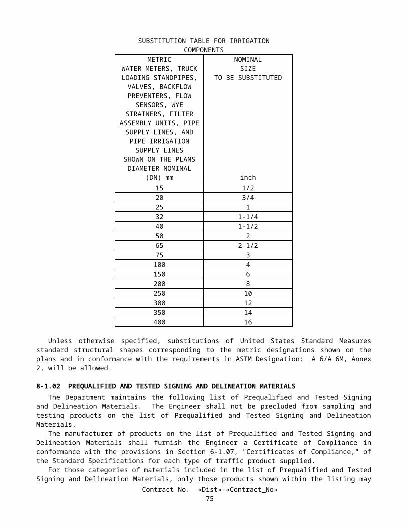
WATER POLLUTION CONTROL COST BREAK-DOWN
Contract No. 11-0301U4
UNIT DESCRIPTION UNITAPPROXIMATE
QUANTITY VALUE AMOUNT
TOTAL ____________________
Contract No. «Dist»-«Contract_No»78

SWPPP IMPLEMENTATIONUpon approval of the SWPPP, the Contractor shall be responsible throughout the duration of the project for installing,
constructing, inspecting, maintaining, removing and disposing of the water pollution control practices included in the SWPPP and any amendments. Unless otherwise directed by the Engineer, the Contractor's responsibility for SWPPP implementation shall continue throughout any temporary suspension of work ordered in conformance with the provisions in Section 8 -1.05, "Temporary Suspension of Work," of the Standard Specifications. Requirements for installation, construction, inspection, maintenance, removal, and disposal of water pollution control practices are specified in the Manuals and these special provisions.
If the Contractor or the Engineer identifies a deficiency in any aspect of the implementation of the approved SWPPP or amendments, the deficiency shall be corrected immediately. The deficiency may be corrected at a later date and time if requested by the Contractor and approved by the Engineer in writing, but not later than the onset of precipitation. If the Contractor fails to correct the identified deficiency by the date agreed or prior to the onset of precipitation the project shall be in noncompliance. Attention is directed to Section 5-1.01, "Authority of the Engineer," of the Standard Specifications and the payment sections of these special provisions for possible noncompliance penalties.
If the Contractor fails to conform to the provisions of "Water Pollution Control (Storm Water Pollution Prevention Plan)," the Engineer may order the suspension of construction operations which create water pollution.
Implementation of water pollution control practices may vary by season. The Construction Site BMP Manual and these special provisions shall be followed for control practice selection of year round, rainy season and non-rainy season water pollution control practices.
Year-Round Implementation RequirementsThe Contractor shall have a year-round program for implementing, inspecting and maintaining water pollution control
practices for wind erosion control, tracking control, non-storm water control, and waste management and materials pollution control.
The National Weather Service weather forecast shall be monitored and used by the Contractor on a daily basis. An alternative weather forecast proposed by the Contractor may be used if approved by the Engineer. If precipitation is predicted, the necessary water pollution control practices shall be deployed prior to the onset of the precipitation.
Disturbed soil areas shall be considered active whenever the soil disturbing activities have occurred, continue to occur or will occur during the ensuing 21 days. Non-active areas shall be protected as prescribed in the Construction Site BMP Manual within 14 days of cessation of soil disturbing activities or prior to the onset of precipitation, whichever occurs first.
In order to provide effective erosion control the Contractor may be directed to apply permanent erosion control in small or multiple units as disturbed soil areas are deemed substantially complete by the Engineer. The Contractor’s attention is directed to "Temporary Erosion Control", "Temporary Erosion Control (Type 2 and Type 3)" and "Move-In/Move-Out (Erosion Control)" of these special provisions.
The Contractor shall implement, maintain, and inspect the following temporary sediment control practices on a year-round basis. The listed practices shall remain in place until their use is no longer needed, as determined by the Engineer.
Year-RoundSediment Control Practices
Location used
Temporary Fiber Rolls Adjacent to Los Penasquitos CreekTemporary Gravel Bags Adjacent to Los Penasquitos Creek
Rainy Season RequirementsSoil stabilization and sediment control practices conforming to the requirements in the Special Requirements and
applicable Preparation Manual Minimum Requirements, shall be provided throughout the rainy season, defined as between October 1 and May 1.
An implementation schedule of required soil stabilization and sediment control practices for disturbed soil areas shall be completed not later than 20 days prior to the beginning of each rainy season. The implementation schedule shall identify the soil stabilization and sediment control practices to be implemented and the dates on which the implementation will be 25 percent, 50 percent and 100 percent complete, respectively. Construction activities beginning during the rainy season shall implement applicable soil stabilization and sediment control practices. The Contractor shall implement soil stabilization and sediment control practices a minimum of 10 days prior to the start of the rainy season.
Throughout the defined rainy season, the active disturbed soil area of the project site shall be not more than 4 hectares. The Engineer may approve, on a case-by-case basis, expansions of the active disturbed soil area limit. Soil stabilization and sediment control materials shall be maintained on site sufficient to protect the unprotected disturbed soil area. A detailed
Contract No. «Dist»-«Contract_No»79

plan for the mobilization of sufficient labor and equipment shall be maintained to deploy the water pollution control practices required to protect the project site prior to the onset of precipitation events.
Non-Rainy Season RequirementsThe non-rainy season shall be defined as all days outside the defined rainy season. The Contractor’s attention is directed
to the Construction Site BMP Manual for soil stabilization and sediment control implementation requirements on disturbed soil areas during the non-rainy season. Disturbed soil areas within the project shall be protected in conformance with the requirements in the Construction Site BMP Manual with an effective combination of soil stabilization and sediment control.
MAINTENANCETo ensure the proper implementation and functioning of water pollution control practices, the Contractor shall regularly
inspect and maintain the construction site for the water pollution control practices identified in the SWPPP. The construction site shall be inspected by the Contractor as follows:
A. Prior to a forecast storm;B. After a precipitation event which causes site runoff;C. At 24 hour intervals during extended precipitation events;D. Routinely, a minimum of once every 2 weeks outside of the defined rainy season;E. Routinely, a minimum of once every 2 weeks during the defined rainy season.
The Contractor shall use the Storm Water Quality Construction Site Inspection Checklist provided in the Preparation Manual or an alternative inspection checklist provided by the Engineer. One copy of each site inspection record shall be submitted to the Engineer within 24 hours of completing the inspection.
REPORTING REQUIREMENTS
Report of Discharges, Notices or OrdersIf the Contractor identifies any discharge into receiving waters in a manner causing, or potentially causing, a condition of
pollution, or if the project receives a written notice or order from any regulatory agency, the Contractor shall immediately inform the Engineer. The Contractor shall submit a written report to the Engineer within 7 days of the discharge event, notice, or order. The report shall include the following information:
A. The date, time, location, nature of the operation, and type of discharge, including the cause or nature of the notice or order.
B. The water pollution control practices deployed before the discharge event, or prior to receiving the notice or order.C. The date of deployment and type of water pollution control practices deployed after the discharge event, or after
receiving the notice, or order, including additional measures installed or planned to reduce or prevent reoccurrence.D. An implementation and maintenance schedule for any affected water pollution control practices.
Report of First-Time Non-Storm Water DischargeThe Contractor shall notify the Engineer at least 3 days in advance of each first-time non-storm water discharge event,
excluding exempted discharges. The Contractor shall notify the Engineer of each different operation causing a non-storm water discharge and shall obtain field approval for each first-time non-storm water discharge. Non-storm water discharges shall be monitored at each first-time occurrence and routinely thereafter.
Annual CertificationsBy June 15 of each year, the Contractor shall complete and submit an Annual Construction Activity Certification as
contained in the Preparation Manual to the Engineer.
WATER POLLUTION CONTROL TRAININGThe Contractor's management and supervisory personnel along with workers involved with the placement and
maintenance of storm water pollution prevention “Best Management Practices” shall be trained on general storm water pollution control requirements consistent with the "Caltrans Construction Site Best Management Practices (BMP)" Manual. The training is to be provided by the Contractor. The amount of training provided should be commensurate with the job performed by the employee.
Full compensation for water pollution control training shall be considered as included in the contract lump sum price paid for prepare storm water pollution prevention plan, and no additional compensation will be allowed therefor.
Contract No. «Dist»-«Contract_No»80

PAYMENTThe contract lump sum price paid for prepare storm water pollution prevention plan shall include full compensation for
furnishing all labor, materials, tools, equipment, and incidentals for doing all the work involved in developing, preparing, obtaining approval of, revising, and amending the SWPPP, as shown on the plans, as specified in the Standard Specifications and these special provisions, and as directed by the Engineer.
Attention is directed to Section 9-1.06, "Partial Payments," and Section 9-1.07, "Payment After Acceptance," of the Standard Specifications. Payments for prepare storm water pollution prevention plan will be made as follows:
A. After the SWPPP has been approved by the Engineer, 75 percent of the contract item price for prepare storm water pollution prevention plan will be included in the monthly partial payment estimate; and
B. After acceptance of the contract in conformance with the provisions in Section 7-1.17, "Acceptance of Contract," of the Standard Specifications, payment for the remaining 25 percent of the contract item price for prepare storm water pollution prevention plan will be made in conformance with the provisions in Section 9-1.07.
The contract lump sum price paid for water pollution control shall include full compensation for furnishing all labor, materials, tools, equipment, and incidentals, and for doing all the work involved in installing, constructing, removing, and disposing of water pollution control practices, including non-storm water and waste management and materials pollution water pollution control practices except those shown on the plans and for which there is a contract item of work, and excluding developing, preparing, obtaining approval of, revising, and amending the SWPPP, as shown on the plans, as specified in the Standard Specifications and these special provisions, and as directed by the Engineer.
The cost of maintaining the temporary water pollution control practices shall be divided equally by the State and the Contractor as follows:
Soil StabilizationAll temporary water pollution control practices except:
SS-1 SchedulingSS-2 Preservation of Existing Vegetation
Sediment ControlAll temporary water pollution control practices.
Tracking ControlAll temporary water pollution control practices except:
SC-7 Street Sweeping and Vacuuming
Wind Erosion ControlAll temporary water pollution control practices.
Non-Storm Water ControlNo sharing of maintenance costs will be allowed.
Waste Management & Material ControlNo sharing of maintenance costs will be allowed.
The division of cost will be made by determining the cost of maintaining temporary water pollution control practices in conformance with the provisions in Section 9-1.03, "Force Account Payment," of the Standard Specifications and paying to the Contractor one-half of that cost. Clean-up, repair, removal, disposal, improper installation, and replacement of temporary water pollution control practices damaged by the Contractor's negligence shall not be considered as included in the cost for performing maintenance and no additional compensation will be allowed therefor.
The provisions for sharing maintenance costs shall not relieve the Contractor from the responsibility for providing appropriate maintenance on those items where maintenance costs are not shared.
Full compensation for maintenance costs of water pollution control practices not shared, as specified in these special provisions, shall be considered as included in the contract lump sum price paid for water pollution control and no additional compensation will be allowed therefor.
Contract No. «Dist»-«Contract_No»81

Those water pollution control practices which are shown on the plans and for which there is a contract item of work will be measured and paid for as that contract item of work.
The Engineer will retain an amount equal to 25 percent of the estimated value of the contract work performed during estimate periods in which the Contractor fails to conform to the provisions of this section "Water Pollution Control (Storm Water Pollution Prevention Plan)," as determined by the Engineer.
Retention for failure to conform to the provisions in this section "Water Pollution Control (Storm Water Pollution Prevention Plan)" shall be in addition to the other retention provided for in the contract. The amounts retained for failure of the Contractor to conform to the provisions in this section will be released for payment on the next monthly estimate for partial payment following the date that an approved SWPPP has been implemented and maintained, and water pollution is adequately controlled, as determined by the Engineer.
10-1.03 TEMPORARY EROSION CONTROLTemporary erosion control shall conform to the provisions for erosion control in Section 20-3, "Erosion Control," of the
Standard Specifications and these special provisions.Attention is directed to "Water Pollution Control (Storm Water Pollution Prevention Plan)," of these special provisions.Temporary erosion control work shall consist of applying erosion control materials to embankment slopes, excavation
slopes and other areas designated on the plans. Temporary erosion control work shall be completed in the designated areas during the period starting October 1 and ending May 1, or within 14 days after an area becomes inactive during this period as defined in "Water Pollution Control (Storm Water Pollution Prevention Plan)," of these special provisions.
MATERIALSMaterials shall conform to the provisions in Section 20-2, "Materials," of the Standard Specifications and the following:
Stabilizing EmulsionStabilizing emulsion shall conform to the provisions in Section 20-2.11, "Stabilizing Emulsion," of the Standard
Specifications and these special provisions.The requirement of an effective life of at least one year for stabilizing emulsion shall not apply.Stabilizing emulsion shall be in a dry powder form, may be reemulsifiable, and shall be a processed organic adhesive.
APPLICATIONTemporary erosion control materials shall be applied in one application.The following mixture in the proportions indicated shall be applied with hydro-seeding equipment within 60 minutes
after the seed has been added to the mixture:
Material Kilograms Per Hectare(Slope Measurement)
Fiber 2500Compost 400
Stabilizing Emulsion 300
MEASUREMENT AND PAYMENTTemporary erosion control work will be measured by the square meter or hectare, whichever is designated in the contract
item. The quantity of temporary erosion control to be paid for by the square meter or hectare will be calculated on the basis of actual or computed slope measurements.
Items of temporary erosion control work will be paid for at the contract price per square meter or hectare for temporary erosion control, whichever is involved in the temporary erosion control work and designated in the contract items.
Temporary erosion control placed at locations other than as shown on the project plans or as directed by the Engineer, in conformance with the Contractor's Storm Water Pollution Prevention Plan, will not be measured and will be paid for as specified in "Water Pollution Control (Storm Water Pollution Prevention Plan)," of these special provisions.
No adjustment of compensation will be made for any increase or decrease in the quantities of temporary erosion control required, regardless of the reason for the increase or decrease. The provisions in Section 4-1.03B, "Increased or Decreased Quantities," of the Standard Specifications shall not apply to temporary erosion control.
The cost of maintaining temporary erosion control will be borne equally by the State and the Contractor, as mentioned on "Water Pollution Control (Storm Water Pollution Prevention Plan)", elsewhere in these special provisions.
Contract No. «Dist»-«Contract_No»82

10-1.04 TEMPORARY CULVERTSTemporary culverts shall be furnished, installed, maintained, and later removed as shown on the plans, as specified in
these special provisions and as directed by the Engineer.The size and type of temporary culvert to be installed at each location shall be at the option of the Contractor; however,
the culvert shall be capable of sustaining the intended load and of discharging a quantity of water equivalent to the size of culvert shown on the plans. Adequacy as to equivalent strength and capacity shall be subject to approval, in writing, by the Engineer.
Used materials may be installed provided the used materials are good, sound and are suitable for the purpose intended, as determined by the Engineer.
Excavation and backfill for temporary culverts shall be performed in a manner that will provide adequate support for the culvert with a firm, nonsettling foundation for the roadbeds to be constructed over the culverts.
Temporary culverts that are damaged from any cause during the progress of the work shall be repaired or replaced by the Contractor at the Contractor's expense.
When no longer required for the work as determined by the Engineer, temporary culverts shall be removed. Removed facilities shall become the property of the Contractor and shall be removed from the site of the work, except as otherwise provided in this section.
Removed temporary culverts that are not damaged may be installed in the permanent work provided the culverts conform to the requirements specified for the permanent work and the culverts are new when installed as temporary culverts.
Trenches and pits caused by the removal of temporary culverts shall be backfilled in conformance with the provisions in the second paragraph of Section 15-1.02, "Preservation of Property," of the Standard Specifications.
Regardless of the sizes or kinds of temporary culverts installed, temporary culverts will be measured and paid for by the meter for the sizes of temporary culverts shown on the plans and listed in the Engineer's Estimate in the same manner specified for corrugated metal pipe in Section 66-4.01, "Measurement," and Section 66-4.02, "Payment," of the Standard Specifications.
Full compensation for furnishing and installing, maintaining, removing and disposing of temporary culverts shall be considered as included in the contract prices paid per meter for the various sizes of temporary culverts and no additional compensation will be allowed therefor.
10-1.05 TEMPORARY FIBER ROLLTemporary fiber rolls shall conform to the details shown on the plans, the provisions in Section 20 -3, "Erosion Control,"
of the Standard Specifications and these special provisions.Temporary fiber rolls shall be furnished, installed, maintained, and removed at the locations shown on the plans.Attention is directed to "Water Pollution Control (Storm Water Pollution Prevention Plan)", of these special provisions.
MATERIALSMaterials for temporary fiber rolls shall conform to the provisions in Section 20-2, "Materials," of the Standard
Specifications.Temporary fiber roll shall consist of prefabricated wheat or rice straw in rolls with a minimum diameter of 200 mm. The
rolls shall be bound with an ultraviolet (UV) degradable plastic netting and shall weigh not less than 1.9 kg per meter.Stakes shall be fir or pine and shall have a cross-sectional area of at least 360 mm2 and a minimum length of 600 mm.
INSTALLATIONTemporary fiber roll shall be installed as shown on the plans and in conformance with Section 4, detail SC-5 in the
Construction Site Best Management Practices (BMPs) Manual of the Caltrans Storm Water Quality Handbooks and the manufacturer's recommendations.
Fiber rolls shall be placed on contours with a vertical separation of 3.0 m on center for 1:2 slopes (vertical:horizontal) and steeper.
Temporary fiber rolls shall be maintained to disperse concentrated water runoff and to reduce runoff velocities. When no longer required for the intended purpose, as determined by the Engineer, temporary fiber rolls shall be removed from the site of the work.
MEASUREMENT AND PAYMENTThe quantity of temporary fiber roll will be measured by the meter as determined from one end to the other end along the
surface of the roll.The contract price paid per meter for temporary fiber roll shall include full compensation for furnishing all labor (except
maintenance), materials, tools, equipment, and incidentals, and for doing all the work involved in installing temporary fiber
Contract No. «Dist»-«Contract_No»83

rolls, complete in place, including removal of materials, as shown on the plans, as specified in the Standard Specifications and these special provisions, and as directed by the Engineer.
Temporary fiber roll placed at locations other than as shown on the plans or where directed by the Engineer, in conformance with the Contractor's Storm Water Pollution Prevention Plan, will not be measured and will be paid for as specified in "Water Pollution Control (Storm Water Pollution Prevention Plan)," of these special provisions.
No adjustment of compensation will be made for any increase or decrease in the quantities of temporary fiber roll required, regardless of the reason for the increase or decrease. The provisions in Section 4-1.03B, "Increased or Decreased Quantities," of the Standard Specifications shall not apply to temporary fiber roll.
The cost of maintaining temporary fiber rolls will be borne equally by the State and the Contractor, as mentioned in "Water Pollution Control (Storm Water Pollution Prevention Plan)", elsewhere in these special provisions.
10-1.06 TEMPORARY GRAVEL BAGTemporary gravel bag shall conform to the details shown on the plans and these special provisions.Temporary gravel bag shall be furnished, installed, maintained and removed at the locations shown on the plans.Preparation shall conform to the provisions in Section 20-3.02, "Preparation," of the Standard Specifications.Attention is directed to "Water Pollution Control (Storm Water Pollution Prevention Plan)", of these special provisions.
MATERIALSMaterials shall conform to the provisions in Section 20-2, "Materials," of the Standard Specifications.Gravel bag fabric shall be woven polypropylene, polyethylene or Polyamide with a minimum unit weight of 135 g/m2.
The fabric shall have a mullen burst strength of at least 2067 kPa, conforming to the requirements in ASTM Designation: D 3786 and an ultraviolet (UV) stability exceeding 70 percent.
Gravel bags, when filled, shall have nominal dimensions (length x width x height) of 400 mm x 300 mm x 150 mm, and a filled mass of 13 kg to 22 kg.
Gravel bag fill material shall be non-cohesive gravel, free from deleterious material.
INSTALLATIONTemporary gravel bags placed in multiple layers shall be installed as shown on the plans and in conformance with
Section 4, detail SC-8 in the Construction Site Best Management Practices (BMPs) Manual of the Caltrans Storm Water Quality Handbooks.
Temporary gravel bags placed in a single layer shall be installed along contours with ends abutting. The last 2 meters of the gravel bag row shall be turned up the slope.
Temporary gravel bag shall be maintained to provide for adequate sediment holding capacity. Sediment deposits shall be removed when the deposit reaches one-third of the temporary gravel bag barrier height. Removed sediment shall be deposited within the project in such a way that the sediment is not subject to erosion by wind or water, or as directed by the Engineer.
When no longer required for the intended purpose, as determined by the Engineer, temporary gravel bags shall be removed from the site of the work.
Holes, depressions or any other ground disturbance caused by the removal of the temporary gravel bags shall be backfilled and repaired in conformance with the provisions in the second paragraph of Section 15-1.02, "Preservation of Property," of the Standard Specifications.
MEASUREMENT AND PAYMENTTemporary gravel bags will be measured by the unit as determined from actual count in place.The contract unit price paid for temporary gravel bag shall include full compensation for furnishing all labor (except
maintenance), materials, tools, equipment, and incidentals, and for doing all the work involved in installing temporary gravel bag complete in place, including removal of materials, as shown on the plans, as specified in the Standard Specifications and these special provisions, and as directed by the Engineer.
Temporary gravel bag placed at locations other than as shown on the project plans or directed by the Engineer, in accordance with the Contractor's Storm Water Pollution Prevention Plan, will not be measured and will be paid for as specified in "Water Pollution Control (Storm Water Pollution Prevention Plan)" of these special provisions.
No adjustment of compensation will be made for any increase or decrease in the quantities of temporary gravel bags required, regardless of the reason for the increase or decrease. The provisions in Section 4-1.03B, "Increased or Decreased Quantities," of the Standard Specifications shall not apply to temporary gravel bags.
The cost of maintaining temporary gravel bags will be borne equally by the State and the Contractor, as mentioned in "Water Pollution Control (Storm Water Pollution Prevention Plan)", elsewhere in these special provisions.
Contract No. «Dist»-«Contract_No»84

10-1.07 TEMPORARY CONCRETE WASHOUTTemporary concrete washout shall be constructed, maintained, and later removed as shown on the plans, as specified in
these special provisions, and as directed by the Engineer.Attention is directed to "Water Pollution Control (Storm Water Pollution Prevention Plan)," and "Order of Work,"
elsewhere in these special provisions.Temporary concrete washout shall be located a minimum of 15 meters from downstream storm drain inlets, open
drainage facilities, and watercourses. Each facility shall be located away from construction traffic or access areas to prevent disturbance or tracking. The exact location of the temporary concrete washout will be determined by the Engineer.
A sign shall be erected as shown on the plans. The perimeter of the concrete washout shall be delineated by lath and flagging to prevent accidental access.
Plastic lining shall have a minimum thickness of 12 mils, and shall be firmly held in place with gravel bags placed no more than one meter apart. Plastic lining shall be installed and maintained in accordance with the manufacturers instructions.
Gravel bags shall conform with the provisions for "Temporary Gravel Bag," elsewhere in these special provisions.Maintaining temporary concrete washout shall include removing and disposing of hardened concrete. Concrete waste
materials shall be removed and disposed of in conformance with the provisions in Section 15-3.02, "Removal Methods," of the Standard Specifications.
When temporary concrete washout is no longer required for the work, as determined by the Engineer, the concrete waste shall be removed and disposed of in conformance with the provisions in Section 15-3.02, "Removal Methods," of the Standard Specifications. Materials for temporary concrete washout shall become the property of the Contractor and shall be removed from the site of the work and disposed of outside of the highway right of way in accordance with section 7-1.13, "Disposal of Material Outside the Highway Right of Way" of the Standard Specifications.
Trenches, depressions and pits caused by the removal of temporary concrete washout shall be backfilled in accordance with the provisions in the second paragraph of Section 15-1.02, "Preservation of Property," of the Standard Specifications.
Temporary concrete washout will be measured and paid for by the unit from actual count.The contract unit price paid for temporary concrete washout shall include full compensation for furnishing all labor,
materials, tools, equipment, and incidentals, and for doing all the work involved in constructing temporary concrete washout, complete in place, including temporary gravel bags, excavation, backfill and plastic lining, maintaining, removing and disposing of concrete waste and temporary concrete washout as shown on the plans, as specified in the Standard Specifications and these special provisions, and as directed by the Engineer.
10-1.08 TEMPORARY CONSTRUCTION ENTRANCETemporary construction entrance shall be constructed, maintained, and later removed as shown on the plans, as specified
in these special provisions, and as directed by the Engineer.The exact location of the temporary construction entrance will be determined by the Engineer.Attention is directed to "Water Pollution Control (Storm Water Pollution Prevention Plan)" and "Order of Work"
elsewhere in these special provisions.Filter fabric shall conform to the requirements in Section 68-1, "Underdrains" of the Standard Specifications.The aggregate shall conform to 37.5 mm x 19 mm grading and the requirements in Section 90-3.02, "Coarse Aggregate
Grading" of the Standard Specifications.Aggregate shall be clean and free from vegetable matter and other deleterious substances.Steel plates shall conform to the requirements of the first paragraph in Section 75-1.02 "Miscellaneous Iron and Steel" of
the Standard Specifications.When no longer required for the work, as determined by the Engineer, temporary construction entrance shall be removed
by the Contractor and disposed of outside of the highway right of way in accordance with section 7-1.13, "Disposal of Material Outside the Highway Right of Way" of the Standard Specifications.
Trenches, depressions and pits caused by the removal of temporary construction entrance shall be backfilled in accordance with the provisions in the second paragraph of Section 15-1.02, "Preservation of Property," of the Standard Specifications.
Temporary construction entrance will be paid for by the unit, from actual count.The contract unit price paid for temporary construction entrance shall include full compensation for furnishing all labor
(except maintenance), materials, tools, equipment, and incidentals, and for doing all the work involved in furnishing and installing temporary construction entrance, complete in place, including excavation, steel plates, aggregate and filter fabric, removing, backfilling and disposing of temporary construction entrance as shown on the plans, as specified in the Standard Specifications and these special provisions, and as directed by the Engineer.
The cost of maintaining all temporary construction entrances will be borne equally by the State and the Contractor, as mentioned in "Water Pollution Control (Storm Water Pollution Prevention Plan)," elsewhere in these special provisions.
Contract No. «Dist»-«Contract_No»85

10-1.09 TEMPORARY FENCE AND GATESTemporary fence and gates shall be furnished, constructed, maintained, and later removed as shown on the plans, as
specified in these special provisions and as directed by the Engineer.Except as otherwise specified in this section, temporary fence and gates shall conform to the plan details and the
specifications for permanent fence of similar character as provided in Section 80, "Fences," of the Standard Specifications.Used materials may be installed provided the used materials are good, sound and are suitable for the purpose intended, as
determined by the Engineer.Materials may be commercial quality provided the dimensions and sizes of the materials are equal to, or greater than, the
dimensions and sizes shown on the plans or specified herein.Posts shall be either metal or wood at the Contractor's option.Galvanizing and painting of steel items will not be required.Treating wood with a wood preservative will not be required.Concrete footings for metal posts will not be required. Temporary fence or gates that is damaged during the progress of the work shall be repaired or replaced by the Contractor
at the Contractor's expense.When no longer required for the work, as determined by the Engineer, temporary fence and gates shall be removed.
Removed facilities shall become the property of the Contractor and shall be removed from the site of the work, except as otherwise provided in this section.
Removed temporary fence and gate materials that are not damaged may be constructed in the permanent work provided the materials conform to the requirements specified for the permanent work and such materials are new when used for the temporary fence and gates.
Holes caused by the removal of temporary fence and gates shall be backfilled in conformance with the provisions in the second paragraph of Section 15-1.02, "Preservation of Property," of the Standard Specifications.
The various types and kinds of temporary fence and gates will be measured and paid for in the same manner specified for permanent fence of similar character as provided in Section 80, "Fences," of the Standard Specifications.
Full compensation for maintaining, removing, and disposing of temporary fence and gates shall be considered as included in the contract prices paid per meter for the various types of temporary fence and no additional compensation will be allowed therefor.
10-1.10 TEMPORARY FENCE (TYPE ESA)Temporary fence (Type ESA) shall be furnished and constructed, maintained, and later removed as shown on the plans,
as specified in these special provisions, and as directed by the Engineer.Temporary fence (Type ESA) shall be constructed prior to any clearing and grubbing work and a sufficient distance from
protected plants to enclose all of the foliage canopy and not encroach upon visible roots of the plants. Temporary fence (Type ESA) shall be located unobstructed from view by heavy equipment operators and other construction workers.
Used materials may be installed providing the used materials are good, sound, and are suitable for the purpose intended, as determined by the Engineer.
Materials may be commercial quality providing the dimensions and sizes of the materials are equal to, or greater than, the dimensions and sizes shown on the plans or specified herein. Fabric used for Temporary fence (Type ESA) shall also conform to the following:
Material: Polypropylene or PolyethyleneColor: OrangeMesh opening: 50 mm x 50 mmUV Resistance: Fully StabilizedFabric Height (min.): 1.0 m
Posts shall be either metal or wood at the Contractor's option, shall be suitable for the purpose intended and shall be driven into the soil a minimum of 400 mm. Post spacing shall be adequate to completely support the fence fabric in an upright position. Metal post shall be a minimum size of, 21.5 mm diameter x 1600 mm in length. Wood post shall be minimum of 25 mm x 50 mm x 1600 mm.
Galvanizing and painting of steel items will not be required.Treating wood with wood preservatives will not be required.Concrete footings for posts will not be required.Temporary fence (Type ESA) that is damaged from any cause during the progress of the work shall be repaired or
replaced by the Contractor at the Contractor's expense.
Contract No. «Dist»-«Contract_No»86

When no longer required for the work as determined by the Engineer, temporary fence (Type ESA) shall be removed. Removed facilities shall become the property of the Contractor and shall be removed from the site of the work, except as otherwise provided in this section.
Holes caused by the removal of temporary fence (Type ESA) shall be backfilled in accordance with the provisions in the second paragraph of Section 15-1.02, "Preservation of Property," of the Standard Specifications.
Temporary fence (Type ESA) will be measured in the manner specified for permanent fences as provided in Section 80, “Fences,” of the Standard Specification.
The contract price paid per meter for temporary fence (Type ESA) shall include full compensation for furnishing all labor, materials, tools, equipment, and incidentals, and for doing all the work involved in installing, maintaining, and removing, as shown on the plans, as specified in the Standard Specifications and these special provisions, and as directed by the Engineer.
10-1.11 PRESERVATION OF PROPERTYAttention is directed to Section 7-1.11, "Preservation of Property," of the Standard Specifications and these special
provisions.Existing trees, shrubs and other plants, that are not to be removed as shown on the plans or specified in these special
provisions, and are injured or damaged by reason of the Contractor's operations, shall be replaced by the Contractor. The minimum size of tree replacement shall be 600 mm box and the minimum size of shrub replacement shall be No. 15 container. Replacement ground cover plants shall be from flats and shall be planted 300 mm on center. Replacement of Carpobrotus ground cover plants shall be from cuttings and shall be planted 300 mm on center. Replacement planting shall conform to the requirements in Section 20-4.07, "Replacement," of the Standard Specifications. The Contractor shall water replacement plants in conformance with the provisions in Section 20-4.06, "Watering," of the Standard Specifications.
Damaged or injured plants shall be removed and disposed of outside the highway right of way in conformance with the provisions in Section 7-l.13 of the Standard Specifications.
Replacement planting of injured or damaged trees, shrubs, and other plants shall be completed prior to the start of the plant establishment period. Replacement planting shall conform to the provisions in Section 20-4.05, "Planting," of the Standard Specifications.
10-1.12 RELIEF FROM MAINTENANCE AND RESPONSIBILITYThe Contractor may be relieved of the duty of maintenance and protection for those items not directly connected with
plant establishment work, except highway planting and irrigation systems in conformance with the provisions in Section 7-1.15, "Relief From Maintenance and Responsibility," of the Standard Specifications.
10-1.13 COOPERATIONAttention is directed to Section 7-1.14, "Cooperation," and Section 8-1.10, "Utility and Non-Highway Facilities," of the
Standard Specifications and these special provisions.It is anticipated that work by another contractor (Contract No.11-224404) to perform erosion control in San Diego on
Route 805 from 0,5 km North of Clairemont Mesa Boulevard Overcrossing to 1.0 km North of La Jolla Village Overcrossing (KP 36.9 to KP 42.0) may be in progress adjacent to or within the limits of this project during progress of the work on this contract.
Consecutive on-ramps or off-ramps in the same direction of travel shall not be closed simultaneously unless otherwise provided in these special provisions or permitted by the Engineer.
10-1.14 PROGRESS SCHEDULE (CRITICAL PATH METHOD)The Contractor shall submit to the Engineer practicable critical path method (CPM) progress schedules in conformance
with these special provisions. Whenever the term "schedule" is used in this section it shall mean CPM progress schedule.Attention is directed to "Payments" of Section 5 of these special provisions.The provisions in Section 8-1.04, "Progress Schedule," of the Standard Specifications shall not apply.
DEFINITIONSThe following definitions shall apply to this section:
A. ACTIVITY.—A task, event or other project element on a schedule that contributes to completing the project. Activities have a description, start date, finish date, duration and one or more logic ties.
B. BASELINE SCHEDULE.—The initial schedule representing the Contractor's work plan on the first working day of the project.
Contract No. «Dist»-«Contract_No»87

C. CONTRACT COMPLETION DATE.—The current extended date for completion of the contract shown on the weekly statement of working days furnished by the Engineer in conformance with the provisions in Section 8-1.06, "Time of Completion," of the Standard Specifications.
D. CRITICAL PATH.—The longest continuous chain of activities for the project that has the least amount of total float of all chains. In general, a delay on the critical path will extend the scheduled completion date.
E. CRITICAL PATH METHOD (CPM).—A network based planning technique using activity durations and the relationships between activities to mathematically calculate a schedule for the entire project.
F. DATA DATE.—The day after the date through which a schedule is current. Everything occurring earlier than the data date is "as-built" and everything on or after the data date is "planned."
G. EARLY COMPLETION TIME.—The difference in time between an early scheduled completion date and the contract completion date.
H. FLOAT.—The difference between the earliest and latest allowable start or finish times for an activity.I. MILESTONE.—An event activity that has zero duration and is typically used to represent the beginning or end of a
certain stage of the project.J. NARRATIVE REPORT.—A document submitted with each schedule that discusses topics related to project
progress and scheduling. K. NEAR CRITICAL PATH.—A chain of activities with total float exceeding that of the critical path but having no
more than 10 working days of total float.L. SCHEDULED COMPLETION DATE.—The planned project finish date shown on the current accepted schedule.M. STATE OWNED FLOAT ACTIVITY.—The activity documenting time saved on the critical path by actions of the
State. It is the last activity prior to the scheduled completion date.N. TIME IMPACT ANALYSIS.—A schedule and narrative report developed specifically to demonstrate what effect a
proposed change or delay has on the current scheduled completion date.O. TOTAL FLOAT.—The amount of time that an activity or chain of activities can be delayed before extending the
scheduled completion date.P. UPDATE SCHEDULE.—A current schedule developed from the baseline or subsequent schedule through regular
monthly review to incorporate as-built progress and any planned changes.
GENERAL REQUIREMENTSThe Contractor shall submit to the Engineer baseline, monthly update and final update schedules, each consistent in all
respects with the time and order of work requirements of the contract. The project work shall be executed in the sequence indicated on the current accepted schedule.
Schedules shall show the order in which the Contractor proposes to carry out the work with logical links between time-scaled work activities, and calculations made using the critical path method to determine the controlling operation or operations. The Contractor is responsible for assuring that all activity sequences are logical and that each schedule shows a coordinated plan for complete performance of the work.
The Contractor shall produce schedules using computer software and shall furnish compatible software for the Engineer's exclusive possession and use. The Contractor shall furnish network diagrams, narrative reports, tabular reports and schedule data as parts of each schedule submittal.
Schedules shall include, but not be limited to, activities that show the following that are applicable to the project:
A. Project characteristics, salient features, or interfaces, including those with outside entities, that could affect time of completion.
B. Project start date, scheduled completion date and other milestones.C. Work performed by the Contractor, subcontractors and suppliers.D. Submittal development, delivery, review and approval, including those from the Contractor, subcontractors and
suppliers.E. Procurement, delivery, installation and testing of materials, plants and equipment.F. Testing and settlement periods.G. Utility notification and relocation.H. Erection and removal of falsework and shoring.I. Major traffic stage switches.J. Finishing roadway and final cleanup.K. State-owned float as the predecessor activity to the scheduled completion date.
Schedules shall have not less than 50 and not more than 500 activities, unless otherwise authorized by the Engineer. The number of activities shall be sufficient to assure adequate planning of the project, to permit monitoring and evaluation of progress, and to do an analysis of time impacts.
Contract No. «Dist»-«Contract_No»88
Schedule activities shall include the following:
A. A clear and legible description.B. Start and finish dates.C. A duration of not less than one working day, except for event activities, and not more than 20 working days, unless
otherwise authorized by the Engineer.D. At least one predecessor and one successor activity, except for project start and finish milestones.E. Required constraints.F. Codes for responsibility, stage, work shifts, location and contract pay item numbers.
The Contractor may show early completion time on any schedule provided that the requirements of the contract are met. Early completion time shall be considered a resource for the exclusive use of the Contractor. The Contractor may increase early completion time by improving production, reallocating resources to be more efficient, performing sequential activities concurrently or by completing activities earlier than planned. The Contractor may also submit for approval a cost reduction incentive proposal in conformance with the provisions in Section 5-1.14, "Cost Reduction Incentive," of the Standard Specifications that will reduce time of construction.
The Contractor may show a scheduled completion date that is later than the contract completion date on an update schedule, after the baseline schedule is accepted. The Contractor shall provide an explanation for a late scheduled completion date in the narrative report that is included with the schedule.
State-owned float shall be considered a resource for the exclusive use of the State. The Engineer may accrue State-owned float by the early completion of review of any type of required submittal when it saves time on the critical path. The Contractor shall prepare a time impact analysis, when requested by the Engineer, to determine the effect of the action in conformance with the provisions in "Time Impact Analysis" specified herein. The Engineer will document State-owned float by directing the Contractor to update the State-owned float activity on the next update schedule. The Contractor shall include a log of the action on the State-owned float activity and include a discussion of the action in the narrative report. The Engineer may use State-owned float to mitigate past, present or future State delays by offsetting potential time extensions for contract change orders.
The Engineer may adjust contract working days for ordered changes that affect the scheduled completion date, in conformance with the provisions in Section 4-1.03, "Changes," of the Standard Specifications. The Contractor shall prepare a time impact analysis to determine the effect of the change in conformance with the provisions in "Time Impact Analysis" specified herein, and shall include the impacts acceptable to the Engineer in the next update schedule. Changes that do not affect the controlling operation on the critical path will not be considered as the basis for a time adjustment. Changes that do affect the controlling operation on the critical path will be considered by the Engineer in decreasing time or granting an extension of time for completion of the contract. Time extensions will only be granted if the total float is absorbed and the scheduled completion date is delayed one or more working days because of the ordered change.
The Engineer's review and acceptance of schedules shall not waive any contract requirements and shall not relieve the Contractor of any obligation thereunder or responsibility for submitting complete and accurate information. Schedules that are rejected shall be corrected by the Contractor and resubmitted to the Engineer within 5 working days of notification by the Engineer, at which time a new review period of one week will begin.
Errors or omissions on schedules shall not relieve the Contractor from finishing all work within the time limit specified for completion of the contract. If, after a schedule has been accepted by the Engineer, either the Contractor or the Engineer discover that any aspect of the schedule has an error or omission, it shall be corrected by the Contractor on the next update schedule.
COMPUTER SOFTWAREThe Contractor shall submit to the Engineer for approval a description of proposed software before delivery. The
software shall be the current version of Primavera SureTrak Project Manager for Windows, or equal, and shall be compatible with Windows NT (version 4.0) operating system. If software other than SureTrak is proposed, it shall be capable of generating files that can be imported into SureTrak.
The Contractor shall furnish schedule software and all original software instruction manuals to the Engineer with submittal of the baseline schedule. The furnished schedule software shall become the property of the State and will not be returned to the Contractor. The State will compensate the Contractor in conformance with the provisions in Section 4-1.03, "Extra Work," of the Standard Specifications for replacement of software which is damaged, lost or stolen after delivery to the Engineer.
The Contractor shall instruct the Engineer in the use of the software and provide software support until the contract is accepted. Within 20 working days of contract approval, the Contractor shall provide a commercial 8-hour training session for 2 Department employees in the use of the software at a location acceptable to the Engineer. It is recommended that the Contractor also send at least 2 employees to the same training session to facilitate development of similar knowledge and
Contract No. «Dist»-«Contract_No»89

skills in the use of the software. If software other than SureTrak is furnished, then the training session shall be a total of 16-hours for each Department employee.
NETWORK DIAGRAMS, REPORTS AND DATAThe Contractor shall include the following for each schedule submittal:
A. Two sets of originally plotted, time-scaled network diagrams.B. Two copies of a narrative report.C. Two copies of each of 3 sorts of the CPM software-generated tabular reports.D. One 1.44-megabyte 90 mm (3.5 inch) floppy diskette containing the schedule data.
The time-scaled network diagrams shall conform to the following:
A. Show a continuous flow of information from left to right.B. Be based on early start and early finish dates of activities.C. Clearly show the primary paths of criticality using graphical presentation.D. Be prepared on E-size sheets, 860 mm x 1120 mm (34 inch x 44 inch).E. Include a title block and a timeline on each page.
The narrative report shall be organized in the following sequence with all applicable documents included:
A. Contractor's transmittal letter.B. Work completed during the period.C. Identification of unusual conditions or restrictions regarding labor, equipment or material; including multiple shifts,
6-day work weeks, specified overtime or work at times other than regular days or hours.D. Description of the current critical path.E. Changes to the critical path and scheduled completion date since the last schedule submittal.F. Description of problem areas.G. Current and anticipated delays:
1. Cause of delay.2. Impact of delay on other activities, milestones and completion dates.3. Corrective action and schedule adjustments to correct the delay.
H. Pending items and status thereof:
1. Permits2. Change orders3. Time adjustments4. Non-compliance notices
I. Reasons for an early or late scheduled completion date in comparison to the contract completion date.
Tabular reports shall be software-generated and provide information for each activity included in the project schedule. Three different reports shall be sorted by (1) activity number, (2) early start and (3) total float. Tabular reports shall be 215 mm x 280 mm (8 1/2 inch x 11 inch) in size and shall include, as a minimum, the following applicable information:
A. Data dateB. Activity number and descriptionC. Predecessor and successor activity numbers and descriptionsD. Activity codesE. Scheduled, or actual and remaining durations (work days) for each activityF. Earliest start (calendar) dateG. Earliest finish (calendar) dateH. Actual start (calendar) dateI. Actual finish (calendar) dateJ. Latest start (calendar) dateK. Latest finish (calendar) date
Contract No. «Dist»-«Contract_No»90

L. Free float (work days)M. Total float (work days)N. Percentage of activity complete and remaining duration for incomplete activities.O. LagsP. Required constraints
Schedule submittals will only be considered complete when all documents and data have been provided as described above.
PRE-CONSTRUCTION SCHEDULING CONFERENCEThe Contractor shall schedule and the Engineer will conduct a pre-construction scheduling conference with the
Contractor's project manager and construction scheduler within 10 working days of the approval of the contract. At this meeting the Engineer will review the requirements of this section of the special provisions with the Contractor.
The Contractor shall submit a general time-scaled logic diagram displaying the major activities and sequence of planned operations and shall be prepared to discuss the proposed work plan and schedule methodology that comply with the requirements of these special provisions. If the Contractor proposes deviations to the construction staging of the project, then the general time-scaled logic diagram shall also display the deviations and resulting time impacts. The Contractor shall be prepared to discuss the proposal.
At this meeting, the Contractor shall additionally submit the alphanumeric coding structure and the activity identification system for labeling the work activities. To easily identify relationships, each activity description shall indicate its associated scope or location of work by including such terms as quantity of material, type of work, bridge number, station to station location, side of highway (such as left, right, northbound, southbound), lane number, shoulder, ramp name, ramp line descriptor or mainline.
The Engineer will review the logic diagram, coding structure, and activity identification system, and provide any required baseline schedule changes to the Contractor for implementation.
BASELINE SCHEDULEBeginning the week following the pre-construction scheduling conference, the Contractor shall meet with the Engineer
weekly until the baseline schedule is accepted by the Engineer to discuss schedule development and resolve schedule issues.The Contractor shall submit to the Engineer a baseline schedule within 20 working days of approval of the contract. The
Contractor shall allow 3 weeks for the Engineer's review after the baseline schedule and all support data are submitted. In addition, the baseline schedule submittal will not be considered complete until the computer software is delivered and installed for use in review of the schedule.
The baseline schedule shall include the entire scope of work and how the Contractor plans to complete all work contemplated. The baseline schedule shall show the activities that define the critical path. Multiple critical paths and near-critical paths shall be kept to a minimum. A total of not more than 50 percent of the baseline schedule activities shall be critical or near critical, unless otherwise authorized by the Engineer.
The baseline schedule shall not extend beyond the number of working days specified in these special provisions. The baseline schedule shall have a data date of the first working day of the contract and not include any completed work to date. The baseline schedule shall not attribute negative float or negative lag to any activity.
If the Contractor submits an early completion baseline schedule that shows contract completion in less than 85 percent of the working days specified in these special provisions, the baseline schedule shall be supplemented with resource allocations for every task activity and include time-scaled resource histograms. The resource allocations shall be shown to a level of detail that facilitates report generation based on labor crafts and equipment classes for the Contractor and subcontractors. The Contractor shall use average composite crews to display the labor loading of on-site construction activities. The Contractor shall optimize and level labor to reflect a reasonable plan for accomplishing the work of the contract and to assure that resources are not duplicated in concurrent activities. The time-scaled resource histograms shall show labor crafts and equipment classes to be utilized on the contract. The Engineer may review the baseline schedule activity resource allocations using Means Productivity Standards or equivalent to determine if the schedule is practicable.
UPDATE SCHEDULEThe Contractor shall submit an update schedule and meet with the Engineer to review contract progress, on or before the
first day of each month, beginning one month after the baseline schedule is accepted. The Contractor shall allow 2 weeks for the Engineer's review after the update schedule and all support data are submitted, except that the review period shall not start until the previous month's required schedule is accepted. Update schedules that are not accepted or rejected within the review period will be considered accepted by the Engineer.
The update schedule shall have a data date of the twenty-first day of the month or other date established by the Engineer. The update schedule shall show the status of work actually completed to date and the work yet to be performed as planned.
Contract No. «Dist»-«Contract_No»91

Actual activity start dates, percent complete and finish dates shall be shown as applicable. Durations for work that has been completed shall be shown on the update schedule as the work actually occurred, including Engineer submittal review and Contractor resubmittal times.
The Contractor may include modifications such as adding or deleting activities or changing activity constraints, durations or logic that do not (1) alter the critical path(s) or near critical path(s) or (2) extend the scheduled completion date compared to that shown on the current accepted schedule. The Contractor shall state in writing the reasons for any changes to planned work. If any proposed changes in planned work will result in (1) or (2) above, then the Contractor shall submit a time impact analysis as described herein.
TIME IMPACT ANALYSISThe Contractor shall submit a written time impact analysis (TIA) to the Engineer with each request for adjustment of
contract time, or when the Contractor or Engineer consider that an approved or anticipated change may impact the critical path or contract progress.
The TIA shall illustrate the impacts of each change or delay on the current scheduled completion date or internal milestone, as appropriate. The analysis shall use the accepted schedule that has a data date closest to and prior to the event. If the Engineer determines that the accepted schedule used does not appropriately represent the conditions prior to the event, the accepted schedule shall be updated to the day before the event being analyzed. The TIA shall include an impact schedule developed from incorporating the event into the accepted schedule by adding or deleting activities, or by changing durations or logic of existing activities. If the impact schedule shows that incorporating the event modifies the critical path and scheduled completion date of the accepted schedule, the difference between scheduled completion dates of the two schedules shall be equal to the adjustment of contract time. The Engineer may construct and utilize an appropriate project schedule or other recognized method to determine adjustments in contract time until the Contractor provides the TIA.
The Contractor shall submit a TIA in duplicate within 15 working days of receiving a written request for a TIA from the Engineer. The Contractor shall allow the Engineer 2 weeks after receipt to approve or reject the submitted TIA. All approved TIA schedule changes shall be shown on the next update schedule.
If a TIA submitted by the Contractor is rejected by the Engineer, the Contractor shall meet with the Engineer to discuss and resolve issues related to the TIA. If agreement is not reached, the Contractor will be allowed 15 days from the meeting with the Engineer to give notice in conformance with the provisions in Section 9-1.04, "Notice of Potential Claim," of the Standard Specifications. The Contractor shall only show actual as-built work, not unapproved changes related to the TIA, in subsequent update schedules. If agreement is reached at a later date, approved TIA schedule changes shall be shown on the next update schedule. The Engineer will withhold remaining payment on the schedule contract item if a TIA is requested by the Engineer and not submitted by the Contractor within 15 working days. The schedule item payment will resume on the next estimate after the requested TIA is submitted. No other contract payment will be retained regarding TIA submittals.
FINAL UPDATE SCHEDULEThe Contractor shall submit a final update, as-built schedule with actual start and finish dates for the activities, within
30 days after completion of contract work. The Contractor shall provide a written certificate with this submittal signed by the Contractor's project manager and an officer of the company stating, "To my knowledge and belief, the enclosed final update schedule reflects the actual start and finish dates of the actual activities for the project contained herein." An officer of the company may delegate in writing the authority to sign the certificate to a responsible manager.
RETENTIONThe Department will retain an amount equal to 25 percent of the estimated value of the work performed during each
estimate period in which the Contractor fails to submit an acceptable schedule conforming to the requirements of these special provisions as determined by the Engineer. Schedule retentions will be released for payment on the next monthly estimate for partial payment following the date that acceptable schedules are submitted to the Engineer or as otherwise specified herein. Upon completion of all contract work and submittal of the final update schedule and certification, any remaining retained funds associated with this section, "Progress Schedule (Critical Path Method)", will be released for payment. Retentions held in conformance with this section shall be in addition to other retentions provided for in the contract. No interest will be due the Contractor on retention amounts.
PAYMENTProgress schedule (critical path method) will be paid for at a lump sum price. The contract lump sum price paid for
progress schedule (critical path method) shall include full compensation for furnishing all labor, material, tools, equipment, and incidentals, including computer software, and for doing all the work involved in preparing, furnishing, and updating schedules, and instructing and assisting the Engineer in the use of computer software, as specified in the Standard Specifications and these special provisions, and as directed by the Engineer.
Contract No. «Dist»-«Contract_No»92

Payments for the progress schedule (critical path method) contract item will be made progressively as follows:
A. A total of 25 percent of the item amount or a total of 25 percent of the amount listed for progress schedule (critical path method) in "Payments" of Section 5 of these special provisions, whichever is less, will be paid upon achieving all of the following:
1. Completion of 5 percent of all contract item work.2. Acceptance of all schedules and TIAs required to the time when 5 percent of all contract item work is complete.3. Delivery of schedule software to the Engineer.4. Completion of required schedule software training.
B. A total of 50 percent of the item amount or a total of 50 percent of the amount listed for progress schedule (critical path method) in "Payments" of Section 5 of these special provisions, whichever is less, will be paid upon completion of 25 percent of all contract item work and acceptance of all schedules and TIAs required to the time when 25 percent of all contract item work is complete.
C. A total of 75 percent of the item amount or a total of 75 percent of the amount listed for progress schedule (critical path method) in "Payments" of Section 5 of these special provisions, whichever is less, will be paid upon completion of 50 percent of all contract item work and acceptance of all schedules and TIAs required to the time when 50 percent of all contract item work is complete.
D. A total of 100 percent of the item amount or a total of 100 percent of the amount listed for progress schedule (critical path method) in "Payments" of Section 5 of these special provisions, whichever is less, will be paid upon completion of all contract item work, acceptance of all schedules and TIAs required to the time when all contract item work is complete, and submittal of the certified final update schedule.
If the Contractor fails to complete any of the work or provide any of the schedules required by this section, the Engineer shall make an adjustment in compensation in conformance with the provisions in Section 4-1.03C, "Changes in Character of Work," of the Standard Specifications for the work not performed. Adjustments in compensation for schedules will not be made for any increased or decreased work ordered by the Engineer in furnishing schedules.
10-1.15 OVERHEADOverhead shall conform to these special provisions. The Contractor will be compensated for time-related overhead in
conformance with these special provisions.Attention is directed to "Force Account Payment" and "Progress Schedule (Critical Path Method)" of these special
provisions.The provisions in Section 9-1.08, "Adjustment of Overhead Costs," of the Standard Specifications shall not apply.Time-related overhead shall consist of those overhead costs, including field and home office overhead, that are in
proportion to the time required to complete the work. Time-related overhead shall not include costs that are not related to time, including but not limited to, mobilization, licenses, permits, and any other charges incurred only once during the contract.
Field office overhead expenses include time-related costs associated with the normal and recurring operations of the construction project, and shall not include costs directly attributable to any of the work of the contract. Such time-related costs include, but are not limited to, the salaries and benefits of project managers, general superintendents, field office managers and other field office staff assigned to the project, and rent, utilities, maintenance, security, supplies and equipment costs of the project field office.
Home office overhead or general and administrative expenses refer to the fixed costs of operating the Contractor's business. These costs include, but are not limited to, general administration, insurance, personnel and subcontract administration, purchasing, accounting, and project engineering and estimating. The rate of home office overhead shall exclude expenses specifically related to other contracts or other businesses of the Contractor, equipment coordination, material deliveries, and consultant and legal fees.
The quantity of time-related overhead to be paid will be measured by the working day, as specified in the Engineer's Estimate as WDAY. The estimated amount will be based on the number of working days, excluding any days for plant establishment, as specified in "Beginning of Work, Time of Completion and Liquidated Damages" of these special provisions. In the event an early completion progress schedule, as defined in "Progress Schedule (Critical Path Method)" of these special provisions, is submitted by the Contractor and approved by the Engineer, the quantity of time-related overhead eligible for payment will be based on the total number of working days as specified in "Beginning of Work, Time of Completion and Liquidated Damages" of these special provisions, rather than the Contractor's early completion progress schedule. The quantity of time-related overhead, as measured above, will be adjusted only as a result of suspensions and adjustments of time which revise the current contract completion date and which are also any of the following:
Contract No. «Dist»-«Contract_No»93

A. Suspensions of work ordered in conformance with the provisions in Section 8-1.05, "Temporary Suspension of Work," of the Standard Specifications, except:
1. Suspensions ordered due to weather conditions being unfavorable for the suitable prosecution of the controlling operation or operations; or
2. Suspensions ordered due to the failure on the part of the Contractor to carry out orders given, or to perform any provision of the contract; or
3. Any other suspensions mutually agreed upon between the Engineer and the Contractor.
B. Extensions of time granted by the State in conformance with the provisions in the fifth paragraph in Section 8-1.07, "Liquidated Damages," of the Standard Specifications; or
C. Reductions in contract time set forth in approved contract change orders, in conformance with the provisions in Section 4-1.03, "Changes," of the Standard Specifications.
In the event a cost reduction proposal is submitted by the Contractor, and is subsequently approved by the Engineer, which provides for a reduction in contract time, the contract amount of time-related overhead associated with the reduction in contract time shall be considered as a net savings in the total cost of time-related overhead. The Contractor will be paid 50 percent of the estimated net savings of the time-related overhead, in conformance with the provisions in Section 5-1.14, "Cost Reduction Incentive," of the Standard Specifications.
If the quantity of time-related overhead, measured as specified in this special provision, exceeds 149 percent of the number of working days specified in the Engineer's Estimate, the Contractor shall, within 60 days of the Engineer's written request, submit to the Engineer an audit examination and report performed by an independent Certified Public Accountant of the Contractor's actual overhead costs. The independent Certified Public Accountant's audit examination shall be performed in conformance with the requirements of the American Institute of Certified Public Accountants Attestation Standards. The audit examination and report shall depict the Contractor's project and company-wide financial records and shall specify the actual overall average daily rates for both field and home office overhead for the entire duration of the project, and whether the costs have been properly allocated. The rates of field and home office overhead shall exclude all unallowable costs as determined in the Federal Acquisition Regulations, 48 CFR, Chapter 1, Part 31. The audit examination shall determine if the rates of field and home office overhead:
A. are allowable in conformance with the requirements of the Federal Acquisition Regulations, 48 CFR, Chapter 1, Part 31;
B. are adequately supported by reliable documentation; and C. related solely to the project under examination.
Upon the Engineer's written request, the Contractor shall make its financial records available for audit by the State for the purpose of verifying the actual rate of time-related overhead specified in the audit submitted by the Contractor. The actual rate of time-related overhead specified in the audit, submitted by the Contractor, will be subject to approval by the Engineer.
If the Engineer elects, or if requested in writing by the Contractor, contract item payments for time-related overhead, in excess of 149 percent of the number of working days designated in the Engineer's Estimate, will be adjusted to reflect the actual rate.
The cost of performing an audit examination and submitting the report, requested by the Engineer, will be borne equally by the State and the Contractor. The division of the cost will be made by determining the cost of providing an audit examination in conformance with the provisions of Section 9-1.03B, "Work performed by Special Forces or Other Special Services" of the Standard Specifications, and paying to the Contractor one-half of that cost.
The contract price paid per working day for time-related overhead shall include full compensation for furnishing all labor, materials, tools, equipment, and incidentals, and for doing all the work involved in time-related overhead, complete in place, including all field and home office overhead costs incurred by the Contractor and by any joint venture partner, subcontractor, supplier or other party associated with the Contractor, and the Contractor's share of costs of audits of overhead costs requested by the Engineer, as specified in these special provisions, and as directed by the Engineer. The provisions in Sections 4-1.03B, "Increased or Decreased Quantities," 4-1.03C, "Changes in Character of the Work," of the Standard Specifications shall not apply to time-related overhead.
Full compensation for additional overhead costs involved in the performance of extra work at force account shall be considered as included in the markups specified in "Force Account Payment," of these special provisions.
Full compensation for additional overhead cost involved in performing additional contract item work that is not a controlling operation and for all overhead, other than the time-related overhead measured and paid for as specified in this
Contract No. «Dist»-«Contract_No»94

section "Overhead", shall be considered as included in the various items of work involved, and no additional compensation will be allowed therefor.
For the purpose of making partial payments pursuant to the provisions in Section 9-1.06, "Partial Payments," of the Standard Specifications, the number of working days to be paid for time-related overhead in each monthly partial payment will be the number of working days, specified above to be measured for payment, that occurred during that monthly estimate period. The amount earned per working day for time-related overhead shall be either the contract item price, or 20 percent of the original total contract amount divided by the number of working days specified in "Beginning of Work, Time of Completion and Liquidated Damages," of these special provisions, whichever is the lesser.
After all work has been completed, except plant establishment work, as provided in Section 20-4.08, "Plant Establishment Work," of the Standard Specifications, the amount, if any, of the total contract item price for time-related overhead not yet paid will be included for payment in the first estimate made after completion of all roadway construction work, in conformance with the provisions in Section 9-1.06, "Partial Payments," of the Standard Specifications.
10-1.16 OBSTRUCTIONSAttention is directed to Section 8-1.10, "Utility and Non-Highway Facilities," and Section 15, "Existing Highway
Facilities," of the Standard Specifications and these special provisions.Attention is directed to the existence of certain underground facilities that may require special precautions be taken by
the Contractor to protect the health, safety and welfare of workers and of the public. Facilities requiring special precautions include, but are not limited to: conductors of petroleum products, oxygen, chlorine, and toxic or flammable gases; natural gas in pipelines greater than 150 mm in diameter or pipelines operating at pressures greater than 415 kPa (gage); underground electric supply system conductors or cables, with potential to ground of more than 300 V, either directly buried or in a duct or conduit which do not have concentric grounded or other effectively grounded metal shields or sheaths.
If these facilities are not located on the plans in both alignment and elevation, no work shall be performed in the vicinity of the facilities, except as provided herein for conduit to be placed under pavement, until the owner, or the owner's representative, has located the facility by potholing, probing or other means that will locate and identify the facility. Conduit to be installed under pavement in the vicinity of these facilities shall be placed by the trenching method in conformance with the provisions in "Conduit" of these special provisions. If, in the opinion of the Engineer, the Contractor's operations are delayed or interfered with by reason of the utility facilities not being located by the owner or the owner's representative, the State will compensate the Contractor for the delays to the extent provided in Section 8-1.09, "Right of Way Delays," of the Standard Specifications, and not otherwise, except as provided in Section 8-1.10, "Utility and Non-Highway Facilities," of the Standard Specifications.
The Contractor shall notify the Engineer and the appropriate regional notification center for operators of subsurface installations at least 2 working days, but not more than 14 calendar days, prior to performing any excavation or other work close to any underground pipeline, conduit, duct, wire or other structure. Regional notification centers include, but are not limited to, the following:
Notification Center Telephone NumberUnderground Service Alert-Northern California (USA) 1-800-642-2444
1-800-227-2600Underground Service Alert-Southern California (USA) 1-800-422-4133
1-800-227-2600
No excavation shall be performed within 1.2 m of the following utilities until the owner, or the owner's representative has located the facility by pot holing, probing, or other means that will positively locate and identify the facility both horizontally and vertically. The utility company will be allowed 20 working days to perform this work
The utility owner or the owner's representative shall be present whenever any excavation is performed within 1.2 m of the following utilities.
Contract No. «Dist»-«Contract_No»95

Owner Type LocationSDG&E HP-100 mm Gas
Main“U-5”, Longitudinal to north edge of Sorrento Valley Blvd., “SVB” line Sta. 5+20 to 7+80
SDG&E 20 mm Gas Main “U-5”, Perpendicular to Sorrento Valley Blvd., “SVB” line Sta. 6+25
SDG&E 50 mm Gas Main “U-5”, Longitudinal to east edge of Sorrento Valley Ct.
SDG&E U/G Electric “U-5”, Longitudinal to south edge of Sorrento Valley Blvd., “SVB” line Sta. 5+20 to 7+80
SDG&E U/G Electric “U-5”, Longitudinal to east edge of Sorrento Valley Ct and perpendicular to Sorrento Valley Blvd.,
“SVB” line Sta. 7+20SDG&E U/G Electric “U-5”, Perpendicular to Sorrento Valley Blvd.,
“SVB” line Sta. 5+88 and 6+96SDG&E U/G Electric “U-12”, Longitudinal to east edge of Sorrento
Valley Rd., “SVRM” line Sta. 14+00 to 14+86 and perpendicular to Sta. 14+40
SDG&E HP-100 mm Gas Main
“U-12 & 13”, Longitudinal to south bound of Sorrento Valley Rd., “SVRM” line Sta. 13+80 to
16+70SDG&E U/G Electric “U-22 - 23”, Longitudinal to south edge of Carmel
Mountain Rd., “CMR” line Sta. 1+00 to 5+00SDG&E HP-100 mm Gas
Main“U-22-23”, Longitudinal to south edge of Carmel
Mountain Rd., “CMR” line Sta. 2+10 to 5+00 SDG&E 50 mm Gas Main “U-22”, Longitudinal to south edge of Carmel
Mountain Rd., “CMR” line Sta. 1+00 to 2+10SDG&E 25 mm Gas Main “U-22”, Perpendicular to Carmel Mountain Rd.,
“CMR” line Sta. 1+30 and 2+06SDG&E U/G Electric “U-29-30”, On dirt road west of., “WS” line Sta.
556+15 to 557+45 and on Sorrento Valley Rd., “SVR” line Sta. 330+55 to 333+80
SDG&E U/G Electric “U-30-31”, On Carmel Valley Rd., “CVR” line Sta. 560+60 to 562+80
SDG&E U/G Electric “U-31-32”, On west side of Portofino Circle, “SD” line Sta. 564+85 to 568+00
It is anticipated that the following utility facilities will be relocated prior to the dates shown:
Utility Location Date Utility WorkSDG&E
Under Built O/H electric“U-12”, Roselle St., Route 5 O.C. 12/31/01 Temporary O/H
RelocationSDG&E
150 mm gas“U-20 & 21” Perpendicular to “SD” line
Sta. 540+6803/20/01 Cap/Abandon
TWCU/G Television
N/B off Ramp and S/B on Ramp 12/31/01 Relocate Boxes
SDG&EU/G electric
“U-30”, “CVR” line Sta. 561+20 to 562+80 12/31/01 Construct vault and relocate U/G
electric and splice cables & remove vault
Installation of the following utility facilities will require coordination with the Contractor's operations. The Contractor shall make the necessary arrangements with the utility company, through the Engineer, and shall submit a schedule of work, verified by a representative of the utility company, to the Engineer. The schedule of work shall provide not less than the following number of working days, as defined in Section 8-1.06, "Time of Completion," of the Standard Specifications for the utility company to complete their work:
Contract No. «Dist»-«Contract_No»96

Utility Ownerand
type of facility
Location UtilityN / WDays
Site Prepby
Contractor
UtilityCo.
WorkSan Diego Gas and
ElectricUnder Built O/H
electric
“U-12”, Roselle St., Route 5 O.C.
20/40 Falsework removed from Sorrento Valley Viaduct
(widen) and complete Box Girder finishing at Roselle
St.
Install Under-built O/H and splice cables
San Diego Gas and Electric
O/H electric
“U-12”, Roselle St., Route 5 O.C.
20/40 Provide access around temporary system at
Sorrento Valley Viaduct (widen) at Roselle St
Remove temporary system from service after new cables are spliced and new system
activatedSan Diego Gas and
ElectricO/H electric
“U-20”, West of “CM3” Line Sta.
539+00
20/20 Complete stone columns, clear construction area and provide access around pole
location.
Construct foundation of the electric pole
San Diego Gas and Electric
O/H electric
“U-18-20”, West of “CM3” Line Sta. 539+00 and
East of “NB” Line, Sta. 536+60 to
539+20
20/40 Clear construction area and provide access around
power poles.
Place steel pole & relocate overhead power lines and
remove poles
San Diego Gas and Electric
O/H electric
“U-20 & 22”, West of “CM3”
Line Sta. 539+00 to 543+85
20/40 Clear construction area and provide access around
power poles.
Construct poles & relocate overhead power lines and
remove poles
SDG&EU/G electric
“U-22”,”CMR” line, Sta. 1+20 to
2+50
20/40 Complete subgrade for street widening and S/B
on/off ramp
Relocate Terminator & Install/remove underground
appurtenances and splice cables
Pacific BellU/G telephone
“U-22”,”CMR” line, Sta. 1+20 to
2+50
20/20 Complete subgrade for street widening and S/B on
ramp
Install/remove underground and appurtenances and splice
cablesPacific Bell
U/G telephone “U-22”,”CMR”
line, Sta. 1+80 to 2+60
20/20 Complete subgradeon S/B off ramp
Relocate manhole and Install/remove underground
and appurtenances and splice cables
SDG&E100 mm gas
“U-22”,”CMR” line, Sta. 1+20 to
2+50
20/20 Complete subgrade for street widening and S/B on
ramp
Relocate gas main and appurtenances
TW Cable “U-22 & 23”,”CMR” line, Sta. 1+20 to 4+20
20/30 Complete subgrade for street widening, S/B on ramp and N/B off Ramp
Relocate conduits
SDG&EO/H electric
“U-24 & 26”, West of “CM3”
Line Sta. 543+85 to Left ”SB” line,
Sta. 550+00
20/40 Clear construction area and provide access around
power poles.
Construct poles & relocate overhead power lines and
remove poles
The Utility Working Days shall not begin until both the notification and site preparation requirements have been met.
Refer to the Utility N /W Days column:
N = The minimum number of working days from the date the Engineer receives written notification that a site will be ready for utility work to the date the site is actually ready for utility work
W = The number of working days needed by the utility company to complete the listed Utility Co. Work.
Contract No. «Dist»-«Contract_No»97

10-1.17 DUST CONTROLDust control shall conform to the provisions in Section 10, "Dust Control," of the Standard Specifications and these
special provisions.Contractor's attention is directed to "Material Containing Aerially Deposited Lead" of these special provisions.
10-1.18 MOBILIZATIONMobilization shall conform to the provisions in Section 11, "Mobilization," of the Standard Specifications.
10-1.19 CONSTRUCTION AREA TRAFFIC CONTROL DEVICES Flagging, signs, and all other traffic control devices furnished, installed, maintained, and removed when no longer
required shall conform to the provisions in Section 12, "Construction Area Traffic Control Devices," of the Standard Specifications and these special provisions.
Category 1 traffic control devices are defined as those devices that are small and lightweight (less than 45 kg), and have been in common use for many years. The devices shall be known to be crashworthy by crash testing, crash testing of similar devices, or years of demonstrable safe performance. Category 1 traffic control devices include traffic cones, plastic drums, portable delineators, and channelizers.
If requested by the Engineer, the Contractor shall provide written self-certification for crashworthiness of Category 1 traffic control devices. Self-certification shall be provided by the manufacturer or Contractor and shall include the following: date, Federal Aid number (if applicable), expenditure authorization, district, county, route and kilometer post of project limits; company name of certifying vendor, street address, city, state and zip code; printed name, signature and title of certifying person; and an indication of which Category 1 traffic control devices will be used on the project. The Contractor may obtain a standard form for self-certification from the Engineer.
Category 2 traffic control devices are defined as those items that are small and lightweight (less than 45 kg), that are not expected to produce significant vehicular velocity change, but may otherwise be potentially hazardous. Category 2 traffic control devices include: barricades and portable sign supports.
Category 2 devices purchased on or after October 1, 2000 shall be on the Federal Highway Administration (FHWA) Acceptable Crashworthy Category 2 Hardware for Work Zones list. This list is maintained by FHWA and can be located at the following internet address: http://safety.fhwa.dot.gov/fourthlevel/hardware/listing.cfm?code=workzone. The Department maintains a secondary list at the following internet address: http://www.dot.ca.gov/hq/traffops/signtech/signdel/pdffiles.htm.
Category 2 devices that have not received FHWA acceptance, and were purchased before October 1, 2000, may continue to be used until they complete their useful service life or until January 1, 2003, whichever comes first. Category 2 devices in use that have received FHWA acceptance shall be labeled with the FHWA acceptance letter number and the name of the manufacturer by the start of the project. The label shall be readable. After January 1, 2003, all Category 2 devices without a label shall not be used on the project.
If requested by the Engineer, the Contractor shall provide a written list of Category 2 devices to be used on the project at least 5 days prior to beginning any work using the devices. For each type of device, the list shall indicate the FHWA acceptance letter number and the name of the manufacturer.
Full compensation for providing self-certification for crashworthiness of Category 1 traffic control devices and for providing a list of Category 2 devices used on the project and labeling Category 2 devices as specified shall be considered as included in the prices paid for the various contract items of work requiring the use of the Category 1 or Category 2 traffic control devices and no additional compensation will be allowed therefor.
10-1.20 CONSTRUCTION AREA SIGNSConstruction area signs shall be furnished, installed, maintained, and removed when no longer required in conformance
with the provisions in Section 12, "Construction Area Traffic Control Devices," of the Standard Specifications and these special provisions.
Attention is directed to the provisions in "Prequalified and Tested Signing and Delineation Materials" of these special provisions. Type II retroreflective sheeting shall not be used on construction area sign panels.
Attention is directed to "Construction Project Information Signs" of these special provisions regarding the number and type of construction project information signs to be furnished, erected, maintained, and removed and disposed of.
The Contractor shall notify the appropriate regional notification center for operators of subsurface installations at least 2 working days, but not more than 14 calendar days, prior to commencing excavation for construction area sign posts. The regional notification centers include, but are not limited to, the following:
Contract No. «Dist»-«Contract_No»98

Notification Center Telephone NumberUnderground Service Alert-Northern California (USA) 1-800-642-2444
1-800-227-2600Underground Service Alert-Southern California (USA) 1-800-422-4133
1-800-227-2600
Excavations required to install construction area signs shall be performed by hand methods without the use of power equipment, except that power equipment may be used if it is determined there are no utility facilities in the area of the proposed post holes.
Sign substrates for stationary mounted construction area signs may be fabricated from fiberglass reinforced plastic as specified under "Prequalified and Tested Signing and Delineation Materials" of these special provisions.
10-1.21 MAINTAINING TRAFFICAttention is directed to Sections 7-1.08, "Public Convenience," 7-1.09, "Public Safety," and 12, "Construction Area
Traffic Control Devices," of the Standard Specifications and to the provisions in "Public Safety" of these special provisions and these special provisions. Nothing in these special provisions shall be construed as relieving the Contractor from the responsibilities specified in Section 7-1.09.
Attention is directed to "Traffic Plastic Drums," elsewhere in these special provisions regarding the use of plastic drums in place of portable delineators, cones or Type I or II barricades.
Lane closures shall conform to the provisions in section "Traffic Control System for Lane Closure" of these special provisions.
When performing work on overhead sign structures over pavement, the Contractor shall close the traffic lane and shoulder directly below the work, except when working on overhead sign structures equipped with walkways. When work is to be performed on sign structures equipped with walkways over traffic lanes, the Contractor shall either:
A. Close the traffic lanes and shoulders directly below the work as provided in this Section, "Maintaining Traffic," or,B. Perform the following safety measures:
All safety railings shall be in place.All personnel shall be secured to the sign structure.All tools shall be secured to the structure or to personnel by means of leashes not more than one meter in length.Install close mesh netting on and below the sign structure that will catch any material that may be dropped.
At locations where falsework pavement lighting or pedestrian openings through falsework are designated, falsework lighting shall be installed in conformance with the provisions in Section 86-6.11, "Falsework Lighting," of the Standard Specifications.
Openings shall be provided through bridge falsework for the use of public traffic at each location where falsework is constructed over the streets, routes, or structures listed in the following table. The type, minimum width, height, and number of openings at each location, and the location and maximum spacing of falsework lighting, if required for each opening, shall conform to the requirements in the table. The width of vehicular openings shall be the clear width between temporary railings or other protective work. The spacing shown for falsework pavement lighting is the maximum distance center to center in meters between fixtures.
Carmel Mountain RoadBridge No. 57-314L/R/S
Number Width HeightVehicle Openings 2 9.6 m 4.6 m
Pedestrian Openings 1(eastside)
1.5 m 3.0 m
Location SpacingFalsework Pavement
LightingR and L 9
staggered 1/2
space(Width and Height in meters)(R = Right side of traffic. L = Left side of traffic)(C = Centered overhead)
Contract No. «Dist»-«Contract_No»99

Sorrento Valley Blvd.Bridge No. 57-1069F,Bridge No. 57-1070G
Includes Bike PathNumber Width Height
Vehicle Openings 2 7.7 m 4.6 mPedestrian Openings 1
northside of
eastbound travel way
1.5 m 3.0 m
Location SpacingFalsework Pavement
LightingR 7
(Width and Height in meters)(R = Right side of traffic. L = Left side of traffic)(C = Centered overhead)
Sorrento Valley RoadBridge No. 57-513L/R
&Bridge No. 57-1028F
Number Width HeightVehicle Openings 2 9.6 m 4.6 m
Pedestrian Openings 1 1.5 m 3.0
Location SpacingFalsework Pavement
LightingR and L 9
staggered 1/2
space(Width and Height in meters)(R = Right side of traffic. L = Left side of traffic)(C = Centered overhead)
Roselle StreetBridge No. 57-513
Number Width HeightVehicle Openings 1 9.6 m 4.6 m
Pedestrian Openings(Northside)
1 1.5 m 3.0 m
Location SpacingFalsework Pavement
LightingR and L 9
staggered 1/2
space(Width and Height in meters)(R = Right side of traffic. L = Left side of traffic)(C = Centered overhead)
Contract No. «Dist»-«Contract_No»100

Sorrento Valley Train StationBridge No. 57-513
Number Width HeightRailway Openings 1 11 m 6 m
Location SpacingFalsework Pavement
LightingR and L 12
staggered 1/2
space(Width and Height in meters)(R = Right side of traffic. L = Left side of traffic)(C = Centered overhead)
Carmel Valley RoadBridge No.57-1028F
Number Width HeightVehicle Openings 1 18.3 4.8 m
Location SpacingFalsework Pavement
LightingR, L, C 12,
staggered 1/2
space with C(Width and Height in meters)(R = Right side of traffic. L = Left side of traffic)(C = Centered overhead)
"CV3" line under Southbound 5 ConnectorBridge No. 57-1028F
Number Width HeightVehicle Openings 1 9.6 4.6 m
Location SpacingFalsework Pavement
LightingR and L 9,
staggered 1/2
space(Width and Height in meters)(R = Right side of traffic. L = Left side of traffic)(C = Centered overhead)
(Existing) Bridge Across Los Penasquitos ChannelBridge No. 57-511
Number Width HeightVehicle Openings 1 18.3 m 4.8 m
Location SpacingFalsework Pavement
LightingR, L, C 12,
staggered 1/2
space with C(Width and Height in meters)(R = Right side of traffic. L = Left side of traffic)(C = Centered overhead)
Contract No. «Dist»-«Contract_No»101

Route 5/805 SeparationBridge No. 57-0512
Number Width HeightVehicle Openings 1 18.3 m 4.8 m
Location SpacingFalsework Pavement
LightingR, L, C 12,
staggered 1/2
space with C(Width and Height in meters)(R = Right side of traffic. L = Left side of traffic)(C = Centered overhead)
"AL" and "AR" lines under Route 5/805 SeparationBridge No. 57-0512
Number Width HeightVehicle Openings 2 15.6 4.6
Location SpacingFalsework Pavement
LightingR and L 7
(Width and Height in meters)(R = Right side of traffic. L = Left side of traffic)(C = Centered overhead)
The exact location of openings will be determined by the Engineer.Personal vehicles of the Contractor's employees shall not be parked within the right of way except in the area designated
for the Contractor's use.Whenever vehicles or equipment are parked on the shoulder within 1.8 m of a traffic lane, the shoulder area shall be
closed as shown on the plans.Lanes shall be closed only during the hours shown on the charts included in this section "Maintaining Traffic." Except
work required under Sections 7-1.08 and 7-1.09, work that interferes with public traffic shall be performed only during the hours shown for lane closures.
Charts 1 through 25 shall be used for lane closures from the start of Construction until December 31, 2004. Charts 26 through 48 shall be used for lane closures from January 1, 2005 until completion of the project.
The full width of the traveled way shall be open for use by public traffic when construction operations are not actively in progress.
Designated legal holidays are: January 1st, the third Monday in February, the last Monday in May, July 4th, the first Monday in September, November 11th, Thanksgiving Day, and December 25th. When a designated legal holiday falls on a Sunday, the following Monday shall be a designated legal holiday. When November 11th falls on a Saturday, the preceding Friday shall be a designated legal holiday.
Minor deviations from the requirements of this section concerning hours of work which do not significantly change the cost of the work may be permitted upon the written request of the Contractor, if in the opinion of the Engineer, public traffic will be better served and the work expedited. These deviations shall not be adopted by the Contractor until the Engineer has approved the deviations in writing. All other modifications will be made by contract change order.
Pedestrian access facilities shall be provided through construction areas within the right of way as shown on the plans and as specified herein. Pedestrian walkways shall be surfaced with asphalt concrete, portland cement concrete or timber. The surface shall be skid resistant and free of irregularities. Hand railings shall be provided on each side of pedestrian walkways as necessary to protect pedestrian traffic from hazards due to construction operations or adjacent vehicular traffic. Protective overhead covering shall be provided as necessary to insure protection from falling objects and drip from overhead structures.
In addition to the required openings through falsework, pedestrian facilities shall be provided during pile driving, footing, wall, and other bridge construction operations. At least one walkway shall be available at all times. If the Contractor's operations require the closure of one walkway, then another walkway shall be provided nearby, off the traveled roadway.
Railings shall be constructed of wood, S4S, and shall be painted white. Railings and walkways shall be maintained in good condition. Walkways shall be kept clear of obstructions.
Contract No. «Dist»-«Contract_No»102

Full compensation for providing pedestrian facilities shall be considered as included in the prices paid for the various contract items of work involved and no additional compensation will be allowed therefor.
Chart No. 1 Multilane Lane Requirements
Direction: Northbound SD-5 Location: JCT. RTE. 52 to JCT. RTE. 5/805
a.m. p.m.FROM HOUR TO HOUR 12 1 2 3 4 5 6 7 8 9 10 11 12 1 2 3 4 5 6 7 8 9 10 11 12Mondays through Thursdays 1 1 1 1 1 3 3 2
Fridays 1 1 1 1 1Saturdays 1 1 1 2 2 3 3Sundays 1 1 1 1 2 2 3 3 3 2 2
Day before designated legal holiday 1 1 1 1 1Designated legal holidays
Legend:1 One lane open in direction of travel
2 Two adjacent lanes open in direction of travel
3 Three adjacent lanes open in direction of travel
No lane closure allowed, Freeway Shoulder may be closed
REMARKS:
KP: R 41.76 / R 50.19F=PD0301U4073100KJ
Chart No. 2 Multilane Lane Requirements
Direction: Northbound SD-5 Location: JCT. RTE. 5/805 to Via De la Valle UC
a.m. p.m.FROM HOUR TO HOUR 12 1 2 3 4 5 6 7 8 9 10 11 12 1 2 3 4 5 6 7 8 9 10 11 12Mondays through Thursdays 1 1 1 1 1 3 3 2
Fridays 1 1 1 1 1Saturdays 1 1 2 2 3Sundays 1 1 1 2 2 3 3 3 2
Day before designated legal holiday 1 1 1 1 1Designated legal holidays
Legend:1 One lane open in direction of travel
2 Two adjacent lanes open in direction of travel
3 Three adjacent lanes open in direction of travel
No lane closure allowed, Freeway Shoulder may be closed
REMARKS:
Contract No. «Dist»-«Contract_No»103

KP: R 50.19 / R 58.37F=PD0301U4073100KJ
Chart No. 3 Multilane Lane Requirements
Direction: Southbound SD-5 Location: JCT. RTE. 52 to JCT. RTE. 5/805
a.m. p.m.FROM HOUR TO HOUR 12 1 2 3 4 5 6 7 8 9 10 11 12 1 2 3 4 5 6 7 8 9 10 11 12Mondays through Thursdays 1 1 1 1 1 3 2 2
Fridays 1 1 1 1 1Saturdays 1 1 1 2 3 3Sundays 1 1 1 1 2 2 3 3 2 2
Day before designated legal holiday 1 1 1 1 1Designated legal holidays
Legend:1 One lane open in direction of travel
2 Two adjacent lanes open in direction of travel
3 Three adjacent lanes open in direction of travel
No lane closure allowed, Freeway Shoulder may be closed
REMARKS:
KP: R 41.76 / R 50.19F=PD0301U4073100KJ
Contract No. «Dist»-«Contract_No»104

Chart No. 4 Multilane Lane Requirements
Direction: Southbound SD-5 Location: JCT. RTE. 5/805 to Via De La Valle UC
a.m. p.m.FROM HOUR TO HOUR 12 1 2 3 4 5 6 7 8 9 10 11 12 1 2 3 4 5 6 7 8 9 10 11 12Mondays through Thursdays 1 1 1 1 1 3 2 2
Fridays 1 1 1 1 1Saturdays 1 1 1 2 3Sundays 1 1 1 1 2 3 3 3 3 2
Day before designated legal holiday 1 1 1 1 1Designated legal holidays
Legend:1 One lane open in direction of travel
2 Two adjacent lanes open in direction of travel
3 Three adjacent lanes open in direction of travel
No lane closure allowed, Freeway Shoulder may be closed
REMARKS:
KP: R 50.19 / R 58.37F=PD0301U4073100KJ
Chart No. 5 Multilane Lane Requirements
Direction: Northbound SD-805 Location: JCT. RTE. 52 to JCT. RTE. 5/805
a.m. p.m.FROM HOUR TO HOUR 12 1 2 3 4 5 6 7 8 9 10 11 12 1 2 3 4 5 6 7 8 9 10 11 12Mondays through Thursdays 1 1 1 1 2 2 2 2
Fridays 1 1 1 1 2Saturdays 1 1 2 3 3 3 3Sundays 1 1 1 2 2 2 3 3 3 3 2 2
Day before designated legal holiday 1 1 1 1 2Designated legal holidays
Legend:1 One lane open in direction of travel
2 Two adjacent lanes open in direction of travel
3 Three adjacent lanes open in direction of travel
No lane closure allowed, Freeway Shoulder may be closed
REMARKS:
KP: 38.06 / 45.87F=PD0301U4073100KJ
Contract No. «Dist»-«Contract_No»105
Chart No. 6 Multilane Lane Requirements
Direction: Southbound SD-805 Location: JCT. RTE. 52 to JCT. RTE. 5/805
a.m. p.m.FROM HOUR TO HOUR 12 1 2 3 4 5 6 7 8 9 10 11 12 1 2 3 4 5 6 7 8 9 10 11 12Mondays through Thursdays 1 1 1 1 1 2 2 1
Fridays 1 1 1 1 1Saturdays 1 1 1 2 2 3 3Sundays 1 1 1 1 1 2 2 3 3 2 2 1
Day before designated legal holiday 1 1 1 1 1Designated legal holidays
Legend:1 One lane open in direction of travel
2 Two adjacent lanes open in direction of travel
3 Three adjacent lanes open in direction of travel
No lane closure allowed, Freeway Shoulder may be closed
REMARKS:
KP: 38.06 / 45.87F=PD0301U4073100KJ
Contract No. «Dist»-«Contract_No»106
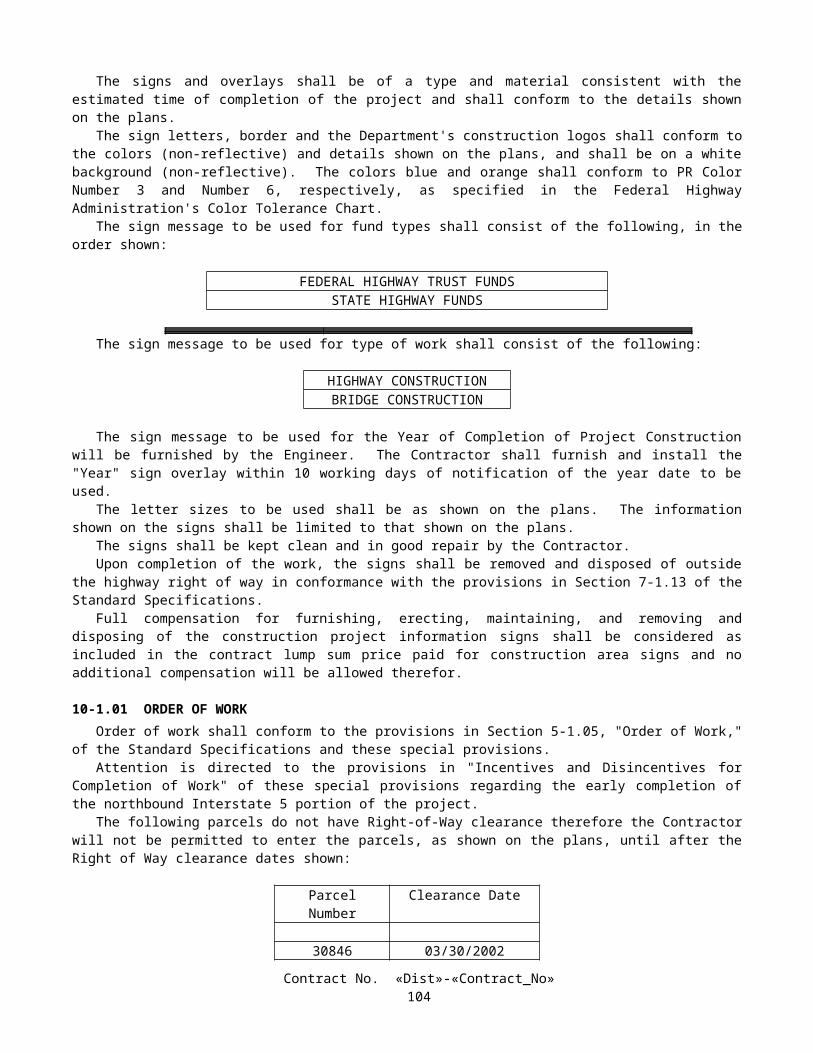
Chart No. 7 Multilane Lane Requirements
Direction: Northbound SD-5 Location: At NB Off-ramp to RTE. 52a.m. p.m.
FROM HOUR TO HOUR 12 1 2 3 4 5 6 7 8 9 10 11 12 1 2 3 4 5 6 7 8 9 10 11 12Mondays through Thursdays F F F F F 3 3 2
Fridays F F F F FSaturdaysSundays 3 2 2
Day before designated legal holiday F F F F FDesignated legal holidays
Legend:F Freeway may be closed
2 Two adjacent lanes open in direction of travel
3 Three adjacent lanes open in direction of travel
No lane closure allowed, Freeway Shoulder may be closed
REMARKS: This chart may not be used in conjunction with Charts No.9, No.9A & No.24.
Close Freeway at NB RTE. 5 Off-ramp to EB RTE. 52.
Detour NB RTE. 5 traffic via northerly on RTE. 5 to NB RTE. 5 Off-ramp to EB RTE. 52 thence easterly on RTE. 52 to EB RTE. 52 Off-ramp to NB RTE. 805 thence northerly on RTE. 805 to NB RTE. 5.NOTE: Place a PCMS (Portable Changeable Message Sign) on NB RTE. 5 at Clairemont Mesa Blvd. warning traffic of the freeway closure/detour ahead.
The following ramps must be closed at the same time as per chart #7A & 25.
NB RTE. 5 On-ramp from Gilman Dr. NB RTE. 5 On-ramp from EB La Jolla Village Dr. NB RTE. 5 On-ramp from WB La Jolla Village Dr. NB RTE. 5 On-ramp from Genesee Ave. WB RTE. 52 Off-ramp to NB RTE. 5KP: R 41.76 / R 50.19
F=PD0301U4073100KJ
Contract No. «Dist»-«Contract_No»107

Chart No. 7A Ramp Lane Requirements
Direction: Northbound SD-5 Location: See Remarksa.m. p.m.
FROM HOUR TO HOUR 12 1 2 3 4 5 6 7 8 9 10 11 12 1 2 3 4 5 6 7 8 9 10 11 12Mondays through Thursdays R R R R R R R R
Fridays R R R R RSaturdaysSundays R R R
Day before designated legal holiday R R R R RDesignated legal holidays
Legend:R Ramp may be closed
No work that interferes with public traffic will be allowed
REMARKS:
This chart is to be used in conjunction with Chart #7 & #25 for full freeway closure only.
Location K.P.
NB On-ramp from Gilman Dr. R 43.527NB On-ramp from EB La Jolla Village Dr. R 45.707NB On-ramp from WB La Jolla Village Dr. R 46.015NB On-ramp from Genesee Ave. R 47.680
F=PD0301U4080300KJ
Contract No. «Dist»-«Contract_No»108

Chart No. 8 Multilane Lane Requirements
Direction: Southbound SD-5 Location: At SB Off-ramp to RTE. 805a.m. p.m.
FROM HOUR TO HOUR 12 1 2 3 4 5 6 7 8 9 10 11 12 1 2 3 4 5 6 7 8 9 10 11 12Mondays through Thursdays F F F F F 3 2 2
Fridays F F F F FSaturdaysSundays 3 3 2
Day before designated legal holiday F F F F FDesignated legal holidays
Legend:F Freeway may be closed
2 Two adjacent lanes open in direction of travel
3 Three adjacent lanes open in direction of travel
No lane closure allowed, Freeway Shoulder may be closed
REMARKS:
Close Freeway at SB Off-ramp to RTE. 805.
Detour SB RTE. 5 traffic via southerly on RTE. 805 to SB RTE. 805 Off-ramp to WB RTE. 52 thence westerly on RTE. 52 to WB RTE. 52 Off-ramp NB/SB RTE. 5.
NOTE: Place a PCMS (Portable Changeable Message Sign) on SB RTE. 5 at Carmel Mountain Rd. warning traffic of the freeway closure/detour ahead.
KP: R 41.76 / R 50.19F=PD0301U4073100KJ
Contract No. «Dist»-«Contract_No»109

Chart No. 9 Multilane Lane Requirements
Direction: Northbound SD-805 Location: At NB Off-ramp to RTE. 52a.m. p.m.
FROM HOUR TO HOUR 12 1 2 3 4 5 6 7 8 9 10 11 12 1 2 3 4 5 6 7 8 9 10 11 12Mondays through Thursdays F F F F 2 2 2
Fridays F F F FSaturdaysSundays 2 2 1
Day before designated legal holiday F F F FDesignated legal holidays
Legend:F Freeway may be closed
1 One lane open in direction of travel
2 Two adjacent lanes open in direction of travel
No lane closure allowed, Freeway Shoulder may be closed
REMARKS: This chart may not be used in conjunction with Charts No.7, No.7A & No.25.
Close Freeway at NB RTE. 805 Off-ramp to WB RTE. 52.
Detour NB RTE. 805 traffic via northerly on RTE. 805 to NB RTE. 805 Off-ramp to WB RTE. 52 thence westerly on RTE. 52 to WB RTE. 52 Off-ramp NB RTE. 5 thence northerly on RTE. 5 to RTE. 805.NOTE: Place a PCMS (Portable Changeable Message Sign) on NB RTE. 805 at Clairemont Mesa Blvd. warning traffic of the freeway closure/detour ahead.
The following ramps must be closed at the same time as per chart #9A& #24.
NB RTE. 805 On-ramp from Governor Dr. NB RTE. 805 On-ramp from WB Miramar Rd. NB RTE. 805 On-ramp from EB La Jolla Village Dr. NB RTE. 805 On-ramp from WB Mira Mesa Blvd. EB Off-ramp to NB RTE. 805 WB Off-ramp to NB RTE. 5KP: 38.06 / 45.87
F=PD0301U4073100KJ
Contract No. «Dist»-«Contract_No»110

Chart No. 9A Ramp Lane Requirements
Direction: Northbound SD-5 Location: See Remarksa.m. p.m.
FROM HOUR TO HOUR 12 1 2 3 4 5 6 7 8 9 10 11 12 1 2 3 4 5 6 7 8 9 10 11 12Mondays through Thursdays R R R R R R R R
Fridays R R R R RSaturdaysSundays R R R
Day before designated legal holiday R R R R RDesignated legal holidays
Legend:R Ramp may be closed
No work that interferes with public traffic will be allowed
REMARKS:
This chart is to be used in conjunction with chart #9 & #24 for full freeway closure only.
Location K.P.
NB On-ramp from Governor Dr. 39.586NB On-ramp from EB La Jolla Village Dr. 42.012 NB On-ramp from WB Miramar Rd. 42.014NB On-ramp from WB Mira Mesa Blvd. 43.910
F=PD0301U4080300KJ
Contract No. «Dist»-«Contract_No»111

Chart No. 10 Multilane Lane Requirements
Direction: Southbound SD-805 Location: At SB On-ramp from RTE. 5a.m. p.m.
FROM HOUR TO HOUR 12 1 2 3 4 5 6 7 8 9 10 11 12 1 2 3 4 5 6 7 8 9 10 11 12Mondays through Thursdays F F F F F 2 2 1
Fridays F F F F FSaturdaysSundays 2 2 1
Day before designated legal holiday F F F F FDesignated legal holidays
Legend:F Freeway may be closed
1 One lane open in direction of travel
2 Two adjacent lanes open in direction of travel
No lane closure allowed, Freeway Shoulder may be closed
REMARKS:
Close Freeway RTE. 805 at RTE. 5.
Detour SB RTE. 5 traffic to SB RTE. 805 via southerly on RTE. 5 to SB RTE. 5 Off-ramp to EB RTE. 52 thence easterly on RTE. 52 to EB RTE. 52 Off-ramp to NB/SB RTE. 805.
NOTE: Place a PCMS (Portable Changeable Message Sign) on SB RTE. 5 at Carmel Mountain Rd. warning traffic of the freeway closure/detour ahead.
KP: 38.06 / 45.87F=PD0301U4073100KJ
Contract No. «Dist»-«Contract_No»112

Chart No. 11 Ramp Lane Requirements
Direction: Northbound SD-5 Location: NB Off-ramp to Roselle St./Sorrento Valley Rd.
a.m. p.m.FROM HOUR TO HOUR 12 1 2 3 4 5 6 7 8 9 10 11 12 1 2 3 4 5 6 7 8 9 10 11 12Mondays through Thursdays R R R R R R R R R R
Fridays R R R R R R R R RSaturdays R R R R R R R R R R R R R R R R R R R R R R R RSundays R R R R R R R R R R R R R R R R R R R R R R R R
Day before designated legal holiday R R R R R R R R RDesignated legal holidays
Legend:
R Ramp may be closed
No work that interferes with public traffic will be allowed
REMARKS:
KP: R 48.372
NOTE: When an Off-ramp is allowed to be closed, place a PCMS (Portable Changeable Message Sign) in the direction of travel allowing the traffic the option to use the preceding Off-ramp and warning them of the ramp closure ahead.
F=PD0301U4080300KJ
Chart No. 12 Ramp Lane Requirements
Direction: Southbound SD-5 Location: SB On-ramp from Carmel Valley Rd.a.m. p.m.
FROM HOUR TO HOUR 12 1 2 3 4 5 6 7 8 9 10 11 12 1 2 3 4 5 6 7 8 9 10 11 12Mondays through Thursdays R R R R R R R R R R R
Fridays R R R R R R R R RSaturdays R R R R R R R R R R R R R R R R RSundays R R R R R R R R R R R R R R R R R R R R
Day before designated legal holiday R R R R R R R R RDesignated legal holidays
Legend:R Ramp may be closed
No work that interferes with public traffic will be allowed
REMARKS:
KP: R 52.769F=PD0301U4080300KJ
Contract No. «Dist»-«Contract_No»113

Chart No. 13 Ramp Lane Requirements
Direction: Southbound SD-5 Location: SB Off-ramp to Carmel Valley Rd.a.m. p.m.
FROM HOUR TO HOUR 12 1 2 3 4 5 6 7 8 9 10 11 12 1 2 3 4 5 6 7 8 9 10 11 12Mondays through Thursdays R R R R R R R R R R R R R R R R R R
Fridays R R R R R R R R RSaturdays R R R R R R R R R R R R R R R R R R R R R R R RSundays R R R R R R R R R R R R R R R R R R R R R R R R
Day before designated legal holiday R R R R R R R R RDesignated legal holidays
Legend:
R Ramp may be closed
No work that interferes with public traffic will be allowed
REMARKS:
KP: R 53.318
NOTE: When an Off-ramp is allowed to be closed, place a PCMS (Portable Changeable Message Sign) in the direction of travel allowing the traffic the option to use the preceding Off-ramp and warning them of the ramp closure ahead.
F=PD0301U4080300KJ
Chart No. 14 Ramp Lane Requirements
Direction: Southbound SD-5 Location: SB Off-ramp to Genesee Ave.a.m. p.m.
FROM HOUR TO HOUR 12 1 2 3 4 5 6 7 8 9 10 11 12 1 2 3 4 5 6 7 8 9 10 11 12Mondays through Thursdays R R R R R R R R R R R
Fridays R R R R R R R R RSaturdays R R R R R R R R R R R R R R R RSundays R R R R R R R R R R R R R R R R R R R R R R R R
Day before designated legal holiday R R R R R R R R RDesignated legal holidays
Legend:R Ramp may be closed
No work that interferes with public traffic will be allowed
REMARKS:
KP: R 47.687
NOTE: When an Off-ramp is allowed to be closed, place a PCMS (Portable Changeable Message Sign) in the direction of travel allowing the traffic the option to use the preceding Off-ramp and warning them of the ramp closure ahead.
F=PD0301U4080300KJ
Contract No. «Dist»-«Contract_No»114

Chart No. 15 Ramp Lane Requirements
Direction: Northbound SD-5 Location: NB On-ramp from Genesee Ave.a.m. p.m.
FROM HOUR TO HOUR 12 1 2 3 4 5 6 7 8 9 10 11 12 1 2 3 4 5 6 7 8 9 10 11 12Mondays through Thursdays R R R R R R R R R
Fridays R R R R R R R R RSaturdays R R R R R R R R R R R R R R R R R R R RSundays R R R R R R R R R R R R R R R R R R R R R
Day before designated legal holiday R R R R R R R R RDesignated legal holidays
Legend:R Ramp may be closed
No work that interferes with public traffic will be allowed
REMARKS:
KP: R 47.680F=PD0301U4080300KJ
Chart No. 16 Ramp Lane Requirements
Direction: Northbound SD-5 Location: NB On-ramp from EB La Jolla Village Dr.a.m. p.m.
FROM HOUR TO HOUR 12 1 2 3 4 5 6 7 8 9 10 11 12 1 2 3 4 5 6 7 8 9 10 11 12Mondays through Thursdays R R R R R R R R R R
Fridays R R R R R R R R RSaturdays R R R R R R R R R R R R R RSundays R R R R R R R R R R R R R R R R R R R
Day before designated legal holiday R R R R R R R R RDesignated legal holidays
Legend:
R Ramp may be closed
No work that interferes with public traffic will be allowed
REMARKS:
KP: R 45.707F=PD0301U4080300KJ
Contract No. «Dist»-«Contract_No»115

Chart No. 17 Ramp Lane Requirements
Direction: Northbound SD-5 Location: NB On-ramp from WB La Jolla Village Dr.a.m. p.m.
FROM HOUR TO HOUR 12 1 2 3 4 5 6 7 8 9 10 11 12 1 2 3 4 5 6 7 8 9 10 11 12Mondays through Thursdays R R R R R R R R R R R R R R R R R R
Fridays R R R R R R R R RSaturdays R R R R R R R R R R R R R R R R R R R R R R R RSundays R R R R R R R R R R R R R R R R R R R R R R R R
Day before designated legal holiday R R R R R RDesignated legal holidays
Legend:R Ramp may be closed
No work that interferes with public traffic will be allowed
REMARKS:
KP: R 46.015F=PD0301U4080300KJ
Chart No. 18 Street Lane Requirements
Direction: Northbound – Southbound Roselle St. Location: Under RTE. 5a.m. p.m.
FROM HOUR TO HOUR 12 1 2 3 4 5 6 7 8 9 10 11 12 1 2 3 4 5 6 7 8 9 10 11 12Mondays through Thursdays X X X X X X X X X X
Fridays X X X X X X X X XSaturdays X X X X X X X X X X X X X X X X X X XSundays X X X X X X X X X X X X X X X X X X X X X X X X
Day before designated legal holiday X X X X X X X X XDesignated legal holidays
Legend:X Street may be closed
No work that interferes with public traffic will be allowed
REMARKS:
Detour NB Roselle St. to SB RTE. 5 traffic via westerly on Sorrento Valley Blvd. to Sorrento Valley Rd. thence southerly on Sorrento Valley Rd. to SB RTE. 805 On-ramp from Sorrento Valley Rd.
Detour SB Roselle St. traffic via southerly on Roselle St. to SB RTE. 5 On-ramp from Roselle St.
F=PD0301U4080300KJ
Contract No. «Dist»-«Contract_No»116

Chart No. 19 Street Lane Requirements
Direction: Eastbound – Westbound Sorrento Valley Blvd.
Location: Under RTE. 805
a.m. p.m.FROM HOUR TO HOUR 12 1 2 3 4 5 6 7 8 9 10 11 12 1 2 3 4 5 6 7 8 9 10 11 12Mondays through Thursdays X X X X X X X X X
Fridays X X X X X X X X XSaturdays X X X X X X X X XSundays X X X X X X X X X X X
Day before designated legal holiday X X X X X X X X XDesignated legal holidays
Legend:X Street may be closed
No work that interferes with public traffic will be allowed
REMARKS:
Detour WB Sorrento Valley Blvd. traffic via westerly on Sorrento Valley Blvd. to Vista Sorrento Pkwy. thence southerly on Vista Sorrento Pkwy. to Mira Mesa Blvd. thence westerly on Mira Mesa Blvd. to Sorrento Valley Rd. thence northerly on Sorrento Valley Rd. to Sorrento Valley Blvd.
Detour EB Sorrento Valley Blvd. traffic via southerly on Sorrento Valley Rd. to Mira Mesa Blvd. thence easterly on Mira Mesa Blvd. to Vista Sorrento Pkwy. thence northerly on Vista Sorrento Pkwy. to Sorrento Valley Blvd.
F=PD0301U4080300KJ
Contract No. «Dist»-«Contract_No»117
Chart No. 20 Street Lane Requirements
Direction: Northbound – Southbound Sorrento Valley Rd.
Location: Under RTE. 5
a.m. p.m.FROM HOUR TO HOUR 12 1 2 3 4 5 6 7 8 9 10 11 12 1 2 3 4 5 6 7 8 9 10 11 12Mondays through Thursdays X X X X X X X X
Fridays X X X X X X X XSaturdays X X X X X X X XSundays X X X X X X X X
Day before designated legal holiday X X X X X X X XDesignated legal holidays
Legend:X Street may be closed
No work that interferes with public traffic will be allowed
REMARKS:
Detour NB Sorrento Valley Road traffic via southerly on Sorrento Valley Road to Vista Sorrento Pkwy. thence northerly on Vista Sorrento Pkwy. to NB RTE. 805 On-ramp from Vista Sorrento Pkwy. thence northerly on RTE. 805 to EB RTE. 56 Off-ramp from RTE. 805/5 thence easterly on RTE. 56 to El Camino Real thence southerly on El Camino Real to Carmel Mountain Rd. thence westerly on Carmel Mountain Rd. to Sorrento Valley Rd.
Detour SB Sorrento Valley Road traffic via northerly on Sorrento Valley Road to Carmel Mountain Rd. thence easterly on Carmel Mountain Rd. to El Camino Real thence northerly on El Camino Real to RTE. 56 thence westerly on RTE. 56 to WB RTE. 56 Off-ramp to RTE. 5/805 thence southerly on RTE. 805 to Sorrento Valley Rd.
F=PD0301U4080300KJ
Chart No. 21 Street Lane Requirements
Direction: Eastbound – Westbound Carmel Mountain Rd.
Location: Over RTE. 5
a.m. p.m.FROM HOUR TO HOUR 12 1 2 3 4 5 6 7 8 9 10 11 12 1 2 3 4 5 6 7 8 9 10 11 12Mondays through Thursdays X X X X X X X X
Fridays X X X X X X X XSaturdays X X X X X X X XSundays X X X X X X X X
Day before designated legal holiday X X X X X X X XDesignated legal holidays
Legend:X Street may be closed
No work that interferes with public traffic will be allowed
REMARKS:
F=PD0301U4080300KJ
Contract No. «Dist»-«Contract_No»118

Chart No. 22 Street Lane Requirements
Direction: Northbound – Southbound Sorrento Valley Ct.
Location: Under RTE. 5
a.m. p.m.FROM HOUR TO HOUR 12 1 2 3 4 5 6 7 8 9 10 11 12 1 2 3 4 5 6 7 8 9 10 11 12Mondays through Thursdays X X X X X X X X
Fridays X X X X X X X XSaturdays X X X X X X X XSundays X X X X X X X X
Day before designated legal holiday X X X X X X X XDesignated legal holidays
Legend:X Street may be closed
No work that interferes with public traffic will be allowed
REMARKS:
Allow local traffic only.
F=PD0301U4080300KJ
Chart No. 23 Street Lane Requirements
Direction: Eastbound – Westbound Carmel Valley Rd. Location: Over RTE. 5a.m. p.m.
FROM HOUR TO HOUR 12 1 2 3 4 5 6 7 8 9 10 11 12 1 2 3 4 5 6 7 8 9 10 11 12Mondays through Thursdays X X X X X X X X
Fridays X X X X XSaturdaysSundays X X X
Day before designated legal holiday X X X X XDesignated legal holidays
Legend:X Street may be closed
No work that interferes with public traffic will be allowed
REMARKS:
F=PD0301U4080300KJ
Contract No. «Dist»-«Contract_No»119
Chart No. 24 Ramp Lane Requirements
Direction: Eastbound SD – 52 Westbound SD – 52
Location: EB Off-ramp to NB RTE. 805;* WB Off-ramp to NB RTE. 805*
a.m. p.m.FROM HOUR TO HOUR 12 1 2 3 4 5 6 7 8 9 10 11 12 1 2 3 4 5 6 7 8 9 10 11 12Mondays through Thursdays R R R R R R
Fridays R R R R RSaturdaysSundays
Day before designated legal holiday R R R R R RDesignated legal holidays
Legend:R Ramp may be closed
No work that interferes with public traffic will be allowed
REMARKS: This chart may not be used in conjunction with Charts No.7, 7A, & 25.
*Ramps/Connectors must be closed simultaneously.
This chart is to be used in conjunction with Charts No. 9 & 9A for full freeway closure only.
Detour EB RTE. 52 Off-ramp to NB RTE. 805 traffic via easterly on RTE. 52 to EB RTE. 52 Off-ramp to SB RTE. 805 thence southerly on RTE. 805 to SB RTE. 805 Off-ramp to WB RTE. 274/Balboa Ave. thence westerly on RTE. 274/Balboa Ave. to WB RTE. 274 Off-ramp to NB RTE. 5.NOTE: Place PCMS (Portable Changeable Message Sign) on EB RTE. 52 at Genesee Ave. – warning public traffic of connector closure/ detour ahead.
Detour WB RTE. 52 Off-ramp to NB RTE. 805 traffic via westerly on RTE. 52 to WB RTE. 52 Off-ramp to NB RTE. 5 thence northerly on RTE. 5 to JCT. RTE. 5/805.NOTE: Place PCMS (Portable Changeable Message Sign) on WB RTE. 52 at Convoy St. – warning public traffic of connector closure/ detour ahead.
KP: 5.423; 6.517
F= PD0310U1012301
Contract No. «Dist»-«Contract_No»120
Chart No. 25 Ramp Lane Requirements
Direction: Westbound SD-52 Location: WB Off-ramp to NB RTE. 5
a.m. p.m.FROM HOUR TO HOUR 12 1 2 3 4 5 6 7 8 9 10 11 12 1 2 3 4 5 6 7 8 9 10 11 12Mondays through Thursdays R R R R R R
Fridays R R R R RSaturdaysSundays
Day before designated legal holiday R R R R R RDesignated legal holidays
Legend:R Ramp may be closed
No work that interferes with public traffic will be allowed
REMARKS:
This chart may not be used in conjunction with Charts No.9, 9A & 25.
This chart is to be used in conjunction with Charts No. 7 & 7A for full freeway closure only.
Detour WB RTE. 52 Off-ramp to NB RTE. 5 traffic via westerly on RTE. 52 to WB RTE. 52 Off-ramp to SB RTE. 5 thence southerly on RTE. 5 to SB RTE. 5 Off-ramp to EB RTE. 274/Balboa Ave. thence easterly on RTE. 274/Balboa Ave. to EB RTE. 274/Balboa Ave. Off-ramp to NB RTE. 805 thence northerly on RTE. 805 to NB RTE. 805 Off-ramp to NB RTE. 5.NOTE: Place PCMS (Portable Changeable Message Sign) on WB RTE. 52 at Regents Rd. – warning public traffic of ramp/connector closure/ detour ahead.
KP: 0.562
F= PD0310U1012301
Contract No. «Dist»-«Contract_No»121

Chart No. 26 Multilane Lane Requirements
Direction: Northbound SD-5 Location: JCT. RTE. 52 to JCT. RTE. 5/805
a.m. p.m.FROM HOUR TO HOUR 12 1 2 3 4 5 6 7 8 9 10 11 12 1 2 3 4 5 6 7 8 9 10 11 12Mondays through Thursdays 1 1 1 1 2 3 3 2
Fridays 2 1 1 1 2Saturdays 1 1 2 2 3 3Sundays 1 1 1 2 2 3 3 3 2
Day before designated legal holiday 2 1 1 1 2Designated legal holidays
Legend:1 One lane open in direction of travel
2 Two adjacent lanes open in direction of travel
3 Three adjacent lanes open in direction of travel
No lane closure allowed, Freeway Shoulder may be closed
REMARKS:
KP: R 41.76 / R 50.19 F=PD0301U4073100KJ
Chart No. 27 Multilane Lane Requirements
Direction: Northbound SD-5 Location: JCT. RTE. 5/805 to Via De la Valle UC
a.m. p.m.FROM HOUR TO HOUR 12 1 2 3 4 5 6 7 8 9 10 11 12 1 2 3 4 5 6 7 8 9 10 11 12Mondays through Thursdays 1 1 1 1 1 3 2
Fridays 1 1 1 1 1Saturdays 1 1 2 3Sundays 1 1 1 2 2 3 3 2
Day before designated legal holiday 1 1 1 1 1Designated legal holidays
Legend:1 One lane open in direction of travel
2 Two adjacent lanes open in direction of travel
3 Three adjacent lanes open in direction of travel
No lane closure allowed, Freeway Shoulder may be closed
REMARKS:
KP: R 50.19 / R 58.37 F=PD0301U4073100KJ
Contract No. «Dist»-«Contract_No»122

Chart No. 28 Multilane Lane Requirements
Direction: Southbound SD-5 Location: JCT. RTE. 52 to JCT. RTE. 5/805
a.m. p.m.FROM HOUR TO HOUR 12 1 2 3 4 5 6 7 8 9 10 11 12 1 2 3 4 5 6 7 8 9 10 11 12Mondays through Thursdays 1 1 1 1 1 3 2 2
Fridays 1 1 1 1 1Saturdays 1 1 1 2 3 3Sundays 1 1 1 2 2 3 3 3 2 2
Day before designated legal holiday 1 1 1 1 1Designated legal holidays
Legend:1 One lane open in direction of travel
2 Two adjacent lanes open in direction of travel
3 Three adjacent lanes open in direction of travel
No lane closure allowed, Freeway Shoulder may be closed
REMARKS:
KP: R 41.76 / R 50.19 F=PD0301U4073100KJ
Chart No. 29 Multilane Lane Requirements
Direction: Southbound SD-5 Location: JCT. RTE. 5/805 to Via De La Valle UC
a.m. p.m.FROM HOUR TO HOUR 12 1 2 3 4 5 6 7 8 9 10 11 12 1 2 3 4 5 6 7 8 9 10 11 12Mondays through Thursdays 1 1 1 1 1 3 2 2
Fridays 1 1 1 1 1Saturdays 1 1 2 2Sundays 1 1 1 2 2 3 3 3 2
Day before designated legal holiday 1 1 1 1 1Designated legal holidays
Legend:1 One lane open in direction of travel
2 Two adjacent lanes open in direction of travel
3 Three adjacent lanes open in direction of travel
No lane closure allowed, Freeway Shoulder may be closed
REMARKS:
KP: R 50.19 / R 58.37 F=PD0301U4073100KJ
Contract No. «Dist»-«Contract_No»123

Chart No. 30 Multilane Lane Requirements
Direction: Northbound SD-805 Location: JCT. RTE. 52 to JCT. RTE. 5/805
a.m. p.m.FROM HOUR TO HOUR 12 1 2 3 4 5 6 7 8 9 10 11 12 1 2 3 4 5 6 7 8 9 10 11 12Mondays through Thursdays 1 1 1 1 2 3 2 2
Fridays 1 1 1 1 2Saturdays 1 1 2 3 3 3Sundays 1 1 1 2 2 2 3 3 3 3 2 2
Day before designated legal holiday 1 1 1 1 2Designated legal holidays
Legend:1 One lane open in direction of travel
2 Two adjacent lanes open in direction of travel
3 Three adjacent lanes open in direction of travel
No lane closure allowed, Freeway Shoulder may be closed
REMARKS:
KP: 38.06 / 45.87 F=PD0301U4073100KJ
Chart No. 31 Multilane Lane Requirements
Direction: Southbound SD-805 Location: JCT. RTE. 52 to JCT. RTE. 5/805
a.m. p.m.FROM HOUR TO HOUR 12 1 2 3 4 5 6 7 8 9 10 11 12 1 2 3 4 5 6 7 8 9 10 11 12Mondays through Thursdays 1 1 1 1 1 3 2 2
Fridays 1 1 1 1 1Saturdays 1 1 1 2Sundays 1 1 1 1 2 2 3 3 3 2 2
Day before designated legal holiday 1 1 1 1 1Designated legal holidays
Legend:1 One lane open in direction of travel
2 Two adjacent lanes open in direction of travel
3 Three adjacent lanes open in direction of travel
No lane closure allowed, Freeway Shoulder may be closed
REMARKS:
KP: 38.06 / 45.87 F=PD0301U4073100KJ
Contract No. «Dist»-«Contract_No»124

Chart No. 32 Multilane Lane Requirements
Direction: Northbound SD-5 Location: At NB Off-ramp to RTE. 52a.m. p.m.
FROM HOUR TO HOUR 12 1 2 3 4 5 6 7 8 9 10 11 12 1 2 3 4 5 6 7 8 9 10 11 12Mondays through Thursdays F F F F 1 3 3 2
Fridays F F F F 1SaturdaysSundays 3 2 2
Day before designated legal holiday F F F F 1Designated legal holidays
Legend:F Freeway may be closed
1 One lane open in direction of travel
2 Two adjacent lanes open in direction of travel
3 Three adjacent lanes open in direction of travel
No lane closure allowed, Freeway Shoulder may be closed
REMARKS:
Close Freeway at NB RTE. 5 Off-ramp to EB RTE. 52.
Detour NB RTE. 5 traffic via northerly on RTE. 5 to NB RTE. 5 Off-ramp to EB RTE. 52 thence easterly on RTE. 52 to EB RTE. 52 Off-ramp to NB RTE. 805 thence northerly on RTE. 805 to NB RTE. 5.
The following ramps must be closed at the same time as per chart #7A
NB RTE. 5 On-ramp from Gilman Dr.
NB RTE. 5 On-ramp from EB La Jolla Village Dr.
NB RTE. 5 On-ramp from WB La Jolla Village Dr.
NB RTE. 5 On-ramp from Genesee Av.
Full freeway closure is for the erection and removal of falsework only.
NOTE: Place a PCMS (Portable Changeable Message Sign) on NB RTE. 5 at Clairemont Mesa Blvd. warning traffic of the freeway closure/detour ahead.
KP: R 41.76 / R 50.19 F=PD0301U4073100KJ
Contract No. «Dist»-«Contract_No»125

Chart No. 33 Multilane Lane Requirements
Direction: Southbound SD-5 Location: At SB Off-ramp to RTE. 805a.m. p.m.
FROM HOUR TO HOUR 12 1 2 3 4 5 6 7 8 9 10 11 12 1 2 3 4 5 6 7 8 9 10 11 12Mondays through Thursdays F F F F F 3 2 2
Fridays F F F F FSaturdaysSundays 3 3 2
Day before designated legal holiday F F F F FDesignated legal holidays
Legend:F Freeway may be closed
2 Two adjacent lanes open in direction of travel
3 Three adjacent lanes open in direction of travel
No lane closure allowed, Freeway Shoulder may be closed
REMARKS:
Close Freeway at SB Off-ramp to RTE. 805.
Detour SB RTE. 5 traffic via southerly on RTE. 805 to SB RTE. 805 Off-ramp to WB RTE. 52 thence westerly on RTE. 52 to WB RTE. 52 Off-ramp NB/SB RTE. 5.
Full freeway closure is for the erection and removal of falsework only.
NOTE: Place a PCMS (Portable Changeable Message Sign) on SB RTE. 5 at Carmel Mountain Rd. warning traffic of the freeway closure/detour ahead.
KP: R 41.76 / R 50.19 F=PD0301U4073100KJ
Contract No. «Dist»-«Contract_No»126

Chart No. 34 Multilane Lane Requirements
Direction: Northbound SD-805 Location: At NB Off-ramp to RTE. 52a.m. p.m.
FROM HOUR TO HOUR 12 1 2 3 4 5 6 7 8 9 10 11 12 1 2 3 4 5 6 7 8 9 10 11 12Mondays through Thursdays F F F F 3 2 2
Fridays F F F FSaturdaysSundays 3 2 1
Day before designated legal holiday F F F FDesignated legal holidays
Legend:F Freeway may be closed
1 One lane open in direction of travel
2 Two adjacent lanes open in direction of travel
3 Three adjacent lanes open in direction of travel
No lane closure allowed, Freeway Shoulder may be closed
REMARKS:
Close Freeway at NB RTE. 805 Off-ramp to WB RTE. 52.
Detour NB RTE. 805 traffic via northerly on RTE. 805 to NB RTE. 805 Off-ramp to WB RTE. 52 thence westerly on RTE. 52 to WB RTE. 52 Off-ramp NB RTE. 5 thence northerly on RTE. 5 to RTE. 805.
The following ramps must be closed at the same time as per chart #9A
NB RTE. 805 On-ramp from Governor Dr.
NB RTE. 805 On-ramp from WB Miramar Rd.
NB RTE. 805 On-ramp from EB La Jolla Village Dr.
NB RTE. 805 On-ramp from WB Mira Mesa Blvd.
Full freeway closure is for the erection and removal of falsework only.
NOTE: Place a PCMS (Portable Changeable Message Sign) on NB RTE. 805 at Clairemont Mesa Blvd. warning traffic of the freeway closure/detour ahead.
KP: 38.06 / 45.87 F=PD0301U4073100KJ
Contract No. «Dist»-«Contract_No»127

Chart No. 34A Ramp Lane Requirements
Direction: Northbound SD-5 Location: See Remarksa.m. p.m.
FROM HOUR TO HOUR 12 1 2 3 4 5 6 7 8 9 10 11 12 1 2 3 4 5 6 7 8 9 10 11 12Mondays through Thursdays R R R R R R R R
Fridays R R R R RSaturdaysSundays R R R
Day before designated legal holiday R R R R RDesignated legal holidays
Legend:R Ramp may be closed
No work that interferes with public traffic will be allowed
REMARKS:
Location K.P.
NB On-ramp from Governor Dr. 39.586NB On-ramp from EB La Jolla Village Dr. 42.012 NB On-ramp from WB Miramar Rd. 42.014NB On-ramp from WB Mira Mesa Blvd. 43.910
This chart is to be used in conjunction with chart #9 for full freeway closure only.
F=PD0301U4080300KJ
Contract No. «Dist»-«Contract_No»128

Chart No. 35 Multilane Lane Requirements
Direction: Southbound SD-805 Location: At SB On-ramp from RTE. 5a.m. p.m.
FROM HOUR TO HOUR 12 1 2 3 4 5 6 7 8 9 10 11 12 1 2 3 4 5 6 7 8 9 10 11 12Mondays through Thursdays 1 F F F F 3 2 1
Fridays 1 F F F FSaturdaysSundays 3 2 2
Day before designated legal holiday 1 F F F FDesignated legal holidays
Legend:F Freeway may be closed
1 One lane open in direction of travel
2 Two adjacent lanes open in direction of travel
3 Three adjacent lanes open in direction of travel
No lane closure allowed, Freeway Shoulder may be closed
REMARKS:
Close Freeway RTE. 805 at RTE. 5.
Detour SB RTE. 5 traffic to SB RTE. 805 via southerly on RTE. 5 to SB RTE. 5 Off-ramp to EB RTE. 52 thence easterly on RTE. 52 to EB RTE. 52 Off-ramp to NB/SB RTE. 805.
Full freeway closure is for the erection and removal of falsework only.
NOTE: Place a PCMS (Portable Changeable Message Sign) on SB RTE. 5 at Carmel Mountain Rd. warning traffic of the freeway closure/detour ahead.
KP: 38.06 / 45.87 F=PD0301U4073100KJ
Contract No. «Dist»-«Contract_No»129

Chart No. 36 Ramp Lane Requirements
Direction: Northbound SD-5 Location: NB Off-ramp to Roselle St./Sorrento Valley Rd.
a.m. p.m.FROM HOUR TO HOUR 12 1 2 3 4 5 6 7 8 9 10 11 12 1 2 3 4 5 6 7 8 9 10 11 12Mondays through Thursdays R R R R R R R R R
Fridays R R R R R R R R RSaturdays R R R R R R R R R R R R R RSundays R R R R R R R R R R R R R R R R R R R R
Day before designated legal holiday R R R R R R R R RDesignated legal holidays
Legend:
R Ramp may be closed
No work that interferes with public traffic will be allowed
REMARKS:
KP: R 48.372
NOTE: When an Off-ramp is allowed to be closed, place a PCMS (Portable Changeable Message Sign) in the direction of travel allowing the traffic the option to use the preceding Off-ramp and warning them of the ramp closure ahead.
F=PD0301U4080300KJ
Chart No. 37 Ramp Lane Requirements
Direction: Southbound SD-5 Location: SB On-ramp from Carmel Valley Rd.a.m. p.m.
FROM HOUR TO HOUR 12 1 2 3 4 5 6 7 8 9 10 11 12 1 2 3 4 5 6 7 8 9 10 11 12Mondays through Thursdays R R R R R R R R R
Fridays R R R R R R R R RSaturdays R R R R R R R R R R R RSundays R R R R R R R R R R R R
Day before designated legal holiday R R R R R R R R RDesignated legal holidays
Legend:R Ramp may be closed
No work that interferes with public traffic will be allowed
REMARKS:
KP: R 52.769 F=PD0301U4080300KJ
Contract No. «Dist»-«Contract_No»130

Chart No. 38 Ramp Lane Requirements
Direction: Southbound SD-5 Location: SB Off-ramp to Carmel Valley Rd.a.m. p.m.
FROM HOUR TO HOUR 12 1 2 3 4 5 6 7 8 9 10 11 12 1 2 3 4 5 6 7 8 9 10 11 12Mondays through Thursdays R R R R R R R R R R R R R R R
Fridays R R R R R R R RSaturdays R R R R R R R R R R R R R R R R R R RSundays R R R R R R R R R R R R R R R R R R R
Day before designated legal holiday R R R R R R R R RDesignated legal holidays
Legend:
R Ramp may be closed
No work that interferes with public traffic will be allowed
REMARKS:
KP: R 53.318
NOTE: When an Off-ramp is allowed to be closed, place a PCMS (Portable Changeable Message Sign) in the direction of travel allowing the traffic the option to use the preceding Off-ramp and warning them of the ramp closure ahead.
F=PD0301U4080300KJ
Chart No. 39 Ramp Lane Requirements
Direction: Southbound SD-5 Location: SB Off-ramp to Gennessee Ave.a.m. p.m.
FROM HOUR TO HOUR 12 1 2 3 4 5 6 7 8 9 10 11 12 1 2 3 4 5 6 7 8 9 10 11 12Mondays through Thursdays R R R R R R R R
Fridays R R R R R R R RSaturdays R R R R R R R R R R RSundays R R R R R R R R R R R R R R
Day before designated legal holiday R R R R R R R R RDesignated legal holidays
Legend:R Ramp may be closed
No work that interferes with public traffic will be allowed
REMARKS:
KP: R 47.687
NOTE: When an Off-ramp is allowed to be closed, place a PCMS (Portable Changeable Message Sign) in the direction of travel allowing the traffic the option to use the preceding Off-ramp and warning them of the ramp closure ahead.
F=PD0301U4080300KJ
Contract No. «Dist»-«Contract_No»131

Chart No. 40 Ramp Lane Requirements
Direction: Northbound SD-5 Location: NB On-ramp from Gennessee Ave.a.m. p.m.
FROM HOUR TO HOUR 12 1 2 3 4 5 6 7 8 9 10 11 12 1 2 3 4 5 6 7 8 9 10 11 12Mondays through Thursdays R R R R R R R R
Fridays R R R R R R R R RSaturdays R R R R R R R R R R R R R RSundays R R R R R R R R R R R R R R R R R
Day before designated legal holiday R R R R R R R R RDesignated legal holidays
Legend:R Ramp may be closed
No work that interferes with public traffic will be allowed
REMARKS:
KP: R 47.680 F=PD0301U4080300KJ
Chart No. 41 Ramp Lane Requirements
Direction: Northbound SD-5 Location: NB On-ramp from EB La Jolla Village Dr.a.m. p.m.
FROM HOUR TO HOUR 12 1 2 3 4 5 6 7 8 9 10 11 12 1 2 3 4 5 6 7 8 9 10 11 12Mondays through Thursdays R R R R R R R R R
Fridays R R R R R R RSaturdays R R R R R R R R R R RSundays R R R R R R R R R R R R R R
Day before designated legal holiday R R R R R R RDesignated legal holidays
Legend:
R Ramp may be closed
No work that interferes with public traffic will be allowed
REMARKS:
KP: R 45.707 F=PD0301U4080300KJ
Contract No. «Dist»-«Contract_No»132
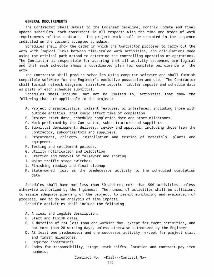
Chart No. 42 Ramp Lane Requirements
Direction: Northbound SD-5 Location: NB On-ramp from WB La Jolla Village Dr.a.m. p.m.
FROM HOUR TO HOUR 12 1 2 3 4 5 6 7 8 9 10 11 12 1 2 3 4 5 6 7 8 9 10 11 12Mondays through Thursdays R R R R R R R R R R R R R R R R
Fridays R R R R R R RSaturdays R R R R R R R R R R R R R R R R R R RSundays R R R R R R R R R R R R R R R R R R R
Day before designated legal holiday R R R R R R RDesignated legal holidays
Legend:R Ramp may be closed
No work that interferes with public traffic will be allowed
REMARKS:
KP: R 46.015 F=PD0301U4080300KJ
Chart No. 43 Street Lane Requirements
Direction: Northbound – Southbound Roselle St. Location: Under RTE. 5a.m. p.m.
FROM HOUR TO HOUR 12 1 2 3 4 5 6 7 8 9 10 11 12 1 2 3 4 5 6 7 8 9 10 11 12Mondays through Thursdays X X X X X X X X X
Fridays X X X X X X X X XSaturdays X X X X X X X X X X X X XSundays X X X X X X X X X X X X X X X X X X X
Day before designated legal holiday X X X X X X X X XDesignated legal holidays
Legend:X Street may be closed
No work that interferes with public traffic will be allowed
REMARKS:
Detour NB Roselle St. to SB RTE. 5 traffic via westerly on Sorrento Valley Blvd. to Sorrento Valley Rd. thence southerly on Sorrento Valley Rd. to SB RTE. 805 On-ramp from Sorrento Valley Rd.
Detour SB Roselle St. traffic via southerly on Roselle St. to SB RTE. 5 On-ramp from Roselle St.
F=PD0301U4080300KJ
Contract No. «Dist»-«Contract_No»133

Chart No. 44 Street Lane Requirements
Direction: Eastbound – Westbound Sorrento Valley Blvd.
Location: Under RTE. 805
a.m. p.m.FROM HOUR TO HOUR 12 1 2 3 4 5 6 7 8 9 10 11 12 1 2 3 4 5 6 7 8 9 10 11 12Mondays through Thursdays X X X X X X X X
Fridays X X X X X X X XSaturdays X X X X X X X X XSundays X X X X X X X X X X
Day before designated legal holiday X X X X X X X XDesignated legal holidays
Legend:X Street may be closed
No work that interferes with public traffic will be allowed
REMARKS:
Detour WB Sorrento Valley Blvd. traffic via westerly on Sorrento Valley Blvd. to Vista Sorrento Pkwy. thence southerly on Vista Sorrento Pkwy. to Mira Mesa Blvd. thence westerly on Mira Mesa Blvd. to Sorrento Valley Rd. thence northerly on Sorrento Valley Rd. to Sorrento Valley Blvd.
Detour EB Sorrento Valley Blvd. traffic via southerly on Sorrento Valley Rd. to Mira Mesa Blvd. thence easterly on Mira Mesa Blvd. to Vista Sorrento Pkwy. thence northerly on Vista Sorrento Pkwy. to Sorrento Valley Blvd.
F=PD0301U4080300KJ
Contract No. «Dist»-«Contract_No»134

Chart No. 45 Street Lane Requirements
Direction: Northbound – Southbound Sorrento Valley Rd.
Location: Under RTE. 5
a.m. p.m.FROM HOUR TO HOUR 12 1 2 3 4 5 6 7 8 9 10 11 12 1 2 3 4 5 6 7 8 9 10 11 12Mondays through Thursdays X X X X X X X
Fridays X X X X X X XSaturdays X X X X X X X XSundays X X X X X X X X
Day before designated legal holiday X X X X X X XDesignated legal holidays
Legend:X Street may be closed
No work that interferes with public traffic will be allowed
REMARKS:
Detour NB Sorrento Valley Road traffic via southerly on Sorrento Valley Road to Vista Sorrento Pkwy. thence northerly on Vista Sorrento Pkwy. to NB RTE. 805 On-ramp from Vista Sorrento Pkwy. thence northerly on RTE. 805 to EB RTE. 56 Off-ramp from RTE. 805/5 thence easterly on RTE. 56 to El Camino Real thence southerly on El Camino Real to Carmel Mountain Rd. thence westerly on Carmel Mountain Rd. to Sorrento Valley Rd.
Detour SB Sorrento Valley Road traffic via northerly on Sorrento Valley Road to Carmel Mountain Rd. thence easterly on Carmel Mountain Rd. to El Camino Real thence northerly on El Camino Real to RTE. 56 thence westerly on RTE. 56 to WB RTE. 56 Off-ramp to RTE. 5/805 thence southerly on RTE. 805 to Sorrento Valley Rd.
F=PD0301U4080300KJ
Chart No. 46 Street Lane Requirements
Direction: Eastbound – Westbound Carmel Mountain Rd.
Location: Over RTE. 5
a.m. p.m.FROM HOUR TO HOUR 12 1 2 3 4 5 6 7 8 9 10 11 12 1 2 3 4 5 6 7 8 9 10 11 12Mondays through Thursdays X X X X X X X
Fridays X X X X X X XSaturdays X X X X X X X XSundays X X X X X X X X
Day before designated legal holiday X X X X X X XDesignated legal holidays
Legend:X Street may be closed
No work that interferes with public traffic will be allowed
REMARKS:
F=PD0301U4080300KJ
Contract No. «Dist»-«Contract_No»135

Chart No. 47 Street Lane Requirements
Direction: Northbound – Southbound Sorrento Valley Ct.
Location: Under RTE. 5
a.m. p.m.FROM HOUR TO HOUR 12 1 2 3 4 5 6 7 8 9 10 11 12 1 2 3 4 5 6 7 8 9 10 11 12Mondays through Thursdays X X X X X X X
Fridays X X X X X X XSaturdays X X X X X X X XSundays X X X X X X X X
Day before designated legal holiday X X X X X X XDesignated legal holidays
Legend:X Street may be closed
No work that interferes with public traffic will be allowed
REMARKS:
Allow local traffic only.
F=PD0301U4080300KJ
Chart No. 48 Street Lane Requirements
Direction: Eastbound – Westbound Carmel Valley Rd. Location: Over RTE. 5a.m. p.m.
FROM HOUR TO HOUR 12 1 2 3 4 5 6 7 8 9 10 11 12 1 2 3 4 5 6 7 8 9 10 11 12Mondays through Thursdays X X X X X X X X
Fridays X X X X XSaturdaysSundays X X X
Day before designated legal holiday X X X X XDesignated legal holidays
Legend:X Street may be closed
No work that interferes with public traffic will be allowed
REMARKS:
F=PD0301U4080300KJ
10-1.22 CLOSURE REQUIREMENTS AND CONDITIONSLane closures shall conform to the provisions in "Maintaining Traffic" of these special provisions and these special
provisions.The term closure, as used herein, is defined as the closure of a traffic lane or lanes, including ramp or connector lanes,
within a single traffic control system.The Contractor shall furnish special portable freeway detour signs as shown on the plans to be used on the detour routes
as directed by the Engineer.
Contract No. «Dist»-«Contract_No»136

CLOSURE SCHEDULEBy noon Monday, the Contractor shall submit a written schedule of planned closures for the following week period,
defined as Friday noon through the following Friday noon.The Closure Schedule shall show the locations and times when the proposed closures are to be in effect. The Contractor
shall use the Closure Schedule request forms furnished by the Engineer. Closure Schedules submitted to the Engineer with incomplete, unintelligible or inaccurate information will be returned for correction and resubmittal. The Contractor will be notified of disapproved closures or closures that require coordination with other parties as a condition of approval.
Amendments to the Closure Schedule, including adding additional closures, shall be submitted to the Engineer, in writing, at least 3 working days in advance of a planned closure. Approval of amendments to the Closure Schedule will be at the discretion of the Engineer.
The Contractor shall confirm, in writing, all scheduled closures by no later than 8:00 a.m. 3 working days prior to the date on which the closure is to be made. Approval or denial of scheduled closures will be made no later than 4:00 p.m. 2 working days prior to the date on which the closure is to be made. Closures not confirmed or approved will not be allowed.
Freeways and ramps may be closed only if signed for closing 3 days in advance. The Contractor shall notify the Engineer not less than 5 calendar days prior to signing the freeway or ramp. If the freeway or ramp is not closed on the posted day, the closure shall be changed to allow 3 days advance notice before closure.
Freeway closure charts are for the erection and removal of falsework and placement and removal of overhead sign bridges and other work as approved in writing by the Engineer.
Simultaneous closure of two consecutive on-ramp or off-ramps in the same direction of travel will not be permitted unless otherwise provided in these special provisions or permitted by the Engineer.
Requests to schedule the closure of two consecutive on-ramps or off-ramps simultaneously in the same direction of travel will not be accepted.
Confirmed closures that are cancelled due to unsuitable weather may be rescheduled at the discretion of the Engineer for the following working day.
CONTINGENCY PLAN The Contractor shall prepare a contingency plan for reopening closures to public traffic. The Contractor shall submit the
contingency plan for a given operation to the Engineer within one working day of the Engineer's request.
LATE REOPENING OF CLOSURESIf a closure is not reopened to public traffic by the specified time, work shall be suspended in conformance with the
provisions in Section 8-1.05, "Temporary Suspension of Work," of the Standard Specifications. The Contractor shall not make any further closures until the Engineer has accepted a work plan, submitted by the Contractor, that will insure that future closures will be reopened to public traffic at the specified time. The Engineer will have 2 working days to accept or reject the Contractor's proposed work plan. The Contractor will not be entitled to any compensation for the suspension of work resulting from the late reopening of closures.
For each 10-minute interval, or fraction thereof past the time specified to reopen the closure, the Department will deduct $8700.00 per interval from moneys due or that may become due the Contractor under the contract.
COMPENSATIONThe Contractor shall notify the Engineer of any delay in the Contractor's operations due to the following conditions, and
if, in the opinion of the Engineer, the Contractor's controlling operation is delayed or interfered with by reason of those conditions, and the Contractor's loss due to that delay could not have been avoided by rescheduling the affected closure or by judicious handling of forces, equipment and plant, the delay will be considered a right of way delay within the meaning of Section 8-1.09, "Right of Way Delays," and compensation for the delay will be determined in conformance with the provisions in Section 8-1.09:
A. The Contractor's proposed Closure Schedule is denied and his planned closures are within the time frame allowed for closures in "Maintaining Traffic" of these special provisions, except that the Contractor will not be entitled to any compensation for amendments to the Closure Schedule that are not approved.
B. The Contractor is denied a confirmed closure.
Should the Engineer direct the Contractor to remove a closure prior to the time designated in the approved Closure Schedule, any delay to the Contractor's schedule due to removal of the closure will be considered a right of way delay within the meaning of Section 8-1.09, "Right of Way Delays," and compensation for the delay will be determined in conformance with the provisions in Section 8-1.09.
Contract No. «Dist»-«Contract_No»137

Furnishing, posting, maintaining, and removing special detour signs shall be considered as included in the contract lump sum price paid for traffic control system and no additional compensation will be allowed therefor.
10-1.23 CONSTRUCTION ZONE ENHANCED ENFORCEMENTConstruction zone enhanced enforcement will be provided by the State as directed by the Engineer and in conformance
with these special provisions. Construction zone enhanced enforcement shall consist of the presence of the California Highway Patrol (CHP) within and near the limits of construction to control the movement of public traffic within the work zone. A total of 6350 hours of California Highway Patrol support is available.
The Contractor shall submit a schedule to the Engineer at least 15 days prior to the performance of work requiring construction zone enhanced enforcement. The schedule shall include all activities requiring construction zone enhanced enforcement and the estimated hours of CHP support required for each activity. The work shall be performed within the number of hours allocated for CHP support.
The Contractor may request additional CHP support for other times and in support of other work activities. The Contractor shall bear the costs and expenses for additional CHP support. The CHP shall be compensated at an agreed rate of $55 per hour per CHP Officer. The agreed rate shall be considered full compensation for each hour, or portion thereof, that a CHP Officer is performing construction area enhanced enforcement. There will be no markup applied to any expenses connected with CHP support. The costs and expenses for requested additional CHP support will be deducted from moneys due to the Contractor.
The Engineer shall make all arrangements with the CHP for scheduled and requested additional construction zone enhanced enforcement.
CHP support shall be scheduled in compliance with the provisions in "Closure Requirements and Conditions" of these special provisions. The Contractor will be notified in writing of assigned CHP support when the Contractor is informed of the approval of requested closures.
Cancellations to previously approved closures scheduled to include construction zone enhancement enforcement shall be submitted in writing to the Engineer at least 36 hours prior to the time when the closure is to be in place. Written notices of cancellation for a closure shall be delivered to the Engineer between the hours of 7:00 a.m. and 3:00 p.m., Monday through Friday, excluding designated legal holidays.
Cancellations with less than the 36-hour written notice may result in charges from the CHP. The Contractor shall bear any costs and expenses resulting from cancellations with less than the 36 hour written notice, except cancellations due to weather or circumstances beyond the control of the Contractor, as determined by the Engineer. The CHP shall be compensated not less than $50.00 per hour and no greater than 4 hours of overtime pay per CHP Officer scheduled to participate in the construction zone enhancement enforcement that is cancelled. The costs and expenses incurred for late cancellations will be deducted from moneys due or that may become due the Contractor.
The presence of the California Highway Patrol will not relieve the Contractor of responsibility of providing for the safety of the public in conformance with the requirements in Section 7-1.09, "Public Safety," nor relieve the Contractor from the responsibility for damage in conformance with the requirements in Section 7-1.12, "Responsibility for Damage," of the Standard Specifications.
10-1.24 TRAFFIC CONTROL SYSTEM FOR LANE CLOSUREA traffic control system shall consist of closing traffic lanes and ramps in conformance with the details shown on the
plans, the provisions in Section 12, "Construction Area Traffic Control Devices," of the Standard Specifications, the provisions under "Maintaining Traffic" and "Construction Area Signs" of these special provisions, and these special provisions.
The provisions in this section will not relieve the Contractor of responsibility for providing additional devices or taking measures as may be necessary to comply with the provisions in Section 7-1.09, "Public Safety," of the Standard Specifications.
During traffic stripe operations and pavement marker placement operations using bituminous adhesive, traffic shall be controlled, at the option of the Contractor, with either stationary or moving lane closures. During other operations, traffic shall be controlled with stationary lane closures. Attention is directed to the provisions in Section 84-1.04, "Protection From Damage," and Section 85-1.06, "Placement," of the Standard Specifications.
If components in the traffic control system are displaced or cease to operate or function as specified, from any cause, during the progress of the work, the Contractor shall immediately repair the components to the original condition or replace the components and shall restore the components to the original location.
STATIONARY LANE CLOSUREWhen lane and ramp closures are made for work periods only, at the end of each work period, components of the traffic
control system, except portable delineators placed along open trenches or excavation adjacent to the traveled way, shall be
Contract No. «Dist»-«Contract_No»138

removed from the traveled way and shoulder. If the Contractor so elects, the components may be stored at selected central locations, designated by the Engineer within the limits of the highway right of way.
Each vehicle used to place, maintain and remove components of a traffic control system on multilane highways shall be equipped with a Type II flashing arrow sign which shall be in operation when the vehicle is being used for placing, maintaining or removing the components. Vehicles equipped with Type II flashing arrow sign not involved in placing, maintaining or removing the components when operated within a stationary type lane closure shall only display the caution display mode. The sign shall be controllable by the operator of the vehicle while the vehicle is in motion. The flashing arrow sign shown on the plans shall not be used on the vehicles which are doing the placing, maintaining and removing of components of a traffic control system and shall be in place before a lane closure requiring the sign's use is completed.
MOVING LANE CLOSUREFlashing arrow signs used in moving lane closures shall be truck-mounted. Changeable message signs used in moving
lane closure operations shall conform to the provisions in Section 12-3.12, "Portable Changeable Message Signs," of the Standard Specifications, except the signs shall be truck-mounted and the full operation height of the bottom of the sign may be less than 2.1 m above the ground, but should be as high as practicable.
Truck-mounted attenuators (TMA) for use in moving lane closures shall be any of the following approved models, or equal:
A. Hexfoam TMA Series 3000, Alpha 1000 TMA Series 1000 and Alpha 2001 TMA Series 2001, manufactured by Energy Absorption Systems, Inc., One East Wacker Drive, Chicago, IL 60601-2076, Telephone (312) 467-6750.
1. Distributor (Northern): Traffic Control Service, Inc., 8585 Thys Court, Sacramento, CA 95828, Telephone 1-800-884-8274, FAX (916) 387-9734.
2. Distributor (Southern): Traffic Control Service, Inc., 1881 Betmor Lane, Anaheim, CA 92805, Telephone 1-800-222-8274.
B. Cal T-001 Model 2 or Model 3, manufacturer and distributor: Hexcel Corporation, 11711 Dublin Boulevard, P.O. Box 2312, Dublin, CA 94568, Telephone (510) 828-4200.
C. Renco Rengard Model Nos. CAM 8-815 and RAM 8-815, manufacturer and distributor: Renco Inc., 1582 Pflugerville Loop Road, P.O. Box 730, Pflugerville, TX 78660-0730, Telephone 1-800-654-8182.
Each TMA shall be individually identified with the manufacturer's name, address, TMA model number, and a specific serial number. The names and numbers shall each be a minimum 13 mm high and located on the left (street) side at the lower front corner. The TMA shall have a message next to the name and model number in 13 mm high letters which states, "The bottom of this TMA shall be _____ mm ± _____ mm above the ground at all points for proper impact performance." Any TMA which is damaged or appears to be in poor condition shall not be used unless recertified by the manufacturer. The Engineer shall be the sole judge as to whether used TMAs supplied under this contract need recertification. Each unit shall be certified by the manufacturer to meet the requirements for TMA in conformance with the standards established by the Transportation Laboratory.
Approvals for new TMA designs proposed as equal to the above approved models shall be in conformance with the procedures (including crash testing) established by the Transportation Laboratory. For information regarding submittal of new designs for evaluation contact: Transportation Laboratory, 5900 Folsom Boulevard, Sacramento, California 95819.
New TMAs proposed as equal to approved TMAs or approved TMAs determined by the Engineer to need recertification shall not be used until approved or recertified by the Transportation Laboratory.
PAYMENTThe contract lump sum price paid for traffic control system shall include full compensation for furnishing all labor,
materials (including signs), tools, equipment, and incidentals, and for doing all the work involved in placing, removing, storing, maintaining, moving to new locations, replacing and disposing of the components of the traffic control system shown on the plans, as specified in the Standard Specifications and these special provisions, and as directed by the Engineer.
The adjustment provisions in Section 4-1.03, "Changes," of the Standard Specifications shall not apply to the item of traffic control system. Adjustments in compensation for traffic control system will be made only for increased or decreased traffic control system required by changes ordered by the Engineer and will be made on the basis of the cost of the increased or decreased traffic control necessary. The adjustment will be made on a force account basis as provided in Section 9 -1.03, "Force Account Payment," of the Standard Specifications for increased work and estimated on the same basis in the case of decreased work.
Traffic control system required by work which is classed as extra work, as provided in Section 4-1.03D of the Standard Specifications, will be paid for as a part of the extra work.
Contract No. «Dist»-«Contract_No»139

10-1.25 TEMPORARY PAVEMENT DELINEATIONTemporary pavement delineation shall be furnished, placed, maintained, and removed in conformance with the
provisions in Section 12-3.01, "General," of the Standard Specifications and these special provisions. Nothing in these special provisions shall be construed as reducing the minimum standards specified in the Manual of Traffic Controls published by the Department or as relieving the Contractor from the responsibilities specified in Section 7-1.09, "Public Safety," of the Standard Specifications.
Attention is directed to "Traffic Plastic Drums," elsewhere in these special provisions regarding the use of traffic plastic drums in place of portable delineators or cones.
GENERALWhenever the work causes obliteration of pavement delineation, temporary or permanent pavement delineation shall be
in place prior to opening the traveled way to public traffic. Laneline pavement delineation shall be provided at all times for traveled ways open to public traffic. On multilane roadways (freeways and expressways) edgeline delineation shall be provided at all times for traveled ways open to public traffic.
The Contractor shall perform the work necessary to establish the alignment of temporary pavement delineation, including required lines or marks. Surfaces to receive temporary pavement delineation shall be dry and free of dirt and loose material. Temporary pavement delineation shall not be applied over existing pavement delineation or other temporary pavement delineation. Temporary pavement delineation shall be maintained until superseded or replaced with a new pattern of temporary pavement delineation or permanent pavement delineation.
Temporary pavement markers, including underlying adhesive, and removable traffic tape which are applied to the final layer of surfacing or existing pavement to remain in place or which conflicts with a subsequent or new traffic pattern for the area shall be removed when no longer required for the direction of public traffic, as determined by the Engineer.
TEMPORARY LANELINE DELINEATIONWhenever lanelines are obliterated and temporary pavement delineation to replace the lines is not shown on the plans,
the minimum laneline delineation to be provided for that area shall be temporary pavement markers placed at longitudinal intervals of not more than 7.3 m. The temporary pavement markers shall be the same color as the laneline the pavement markers replace. Temporary pavement markers shall be, at the option of the Contractor, one of the temporary pavement markers listed for short term day/night use (14 days or less) or long term day/night use (6 months or less) in "Prequalified and Tested Signing and Delineation Materials" of these special provisions. The temporary pavement markers shall be placed in conformance with the manufacturer's instructions. Temporary pavement markers for long term day/night use (6 months or less) shall be cemented to the surfacing with the adhesive recommended by the manufacturer, except epoxy adhesive shall not be used to place the temporary pavement markers in areas where removal of the temporary pavement markers will be required.
Temporary laneline delineation consisting entirely of temporary pavement markers listed for short term day/night use (14 days or less), shall be placed on longitudinal intervals of not more than 7.3 m and shall be used for a maximum of 14 days on lanes opened to public traffic. Prior to the end of the 14 days the permanent pavement delineation shall be placed. If the permanent pavement delineation is not placed within the 14 days, the Contractor shall replace the temporary pavement markers and provide additional temporary pavement delineation and shall bear the cost thereof. The additional temporary pavement delineation to be provided shall be equivalent to the pattern specified for the permanent pavement delineation for the area, as determined by the Engineer.
Full compensation for furnishing, placing, maintaining, and removing the temporary pavement markers (including underlying adhesive, layout (dribble) lines to establish alignment of temporary pavement markers or used for temporary laneline delineation) for those areas where temporary laneline and centerline delineation is not shown on the plans and for providing equivalent patterns of permanent traffic lines for those areas when required, shall be considered as included in the contract prices paid for the items of work that obliterated the laneline and centerline pavement delineation and no separate payment will be made therefor.
TEMPORARY EDGELINE DELINEATIONOn multilane roadways (freeways and expressways), whenever edgelines are obliterated and temporary pavement
delineation to replace those edgelines is not shown on the plans, the edgeline delineation to be provided for those areas adjacent to lanes open to public traffic shall be as follows:
A. Temporary pavement delineation for right edgelines shall, at the option of the Contractor, consist of either a solid 100-mm wide traffic stripe of the same color as the stripe the temporary edgeline delineation replaces, or traffic cones, portable delineators or channelizers placed at longitudinal intervals not to exceed 30 m.
Contract No. «Dist»-«Contract_No»140

B. Temporary pavement delineation for left edgelines shall, at the option of the Contractor, consist of either solid 100-mm wide traffic stripe of the same color as the stripe the temporary edgeline delineation replaces, traffic cones, portable delineators or channelizers placed at longitudinal intervals not to exceed 30 m or temporary pavement markers placed at longitudinal intervals of not more than 1.8 m. Temporary pavement markers used for temporary left edgeline delineation shall be one of the types of temporary pavement markers listed for short term day/night use (14 days or less) or long term day/night use (6 months or less) in "Prequalified and Tested Signing and Delineation Materials" of these special provisions.
Where removal of the 100-mm wide traffic stripe will not be required, painted traffic stripe conforming to the provisions of "Temporary Traffic Stripe (Paint)" of these special provisions may be used. The quantity of temporary traffic stripe (paint) used for this temporary edgeline delineation will not be included in the quantities of tape or paint to be paid for.
The lateral offset for traffic cones, portable delineators or channelizers used for temporary edgeline delineation shall be as determined by the Engineer. If traffic cones or portable delineators are used as temporary pavement delineation for edgelines, the Contractor shall provide personnel to remain at the project site to maintain the cones or delineators during the hours of the day that the portable delineators are in use.
Channelizers used for temporary edgeline delineation shall be the surface mounted type and shall be orange in color. Channelizer bases shall be cemented to the pavement in the same manner provided for cementing pavement markers to pavement in "Pavement Markers" of these special provisions, except epoxy adhesive shall not be used to place channelizers on the top layer of pavement. Channelizers shall be, at the Contractor's option, one of the surface mount types (900 mm) listed in "Prequalified and Tested Signing and Delineation Materials" of these special provisions.
Temporary edgeline delineation shall be removed when no longer required for the direction of public traffic as determined by the Engineer.
Full compensation for furnishing, placing, maintaining, and removing temporary edgeline delineation, including underlying adhesive, for those areas where temporary edgeline delineation is not shown on the plans shall be considered as included in the contract prices paid for the items of work that obliterated the edgeline pavement delineation and no separate payment will be made therefor.
TEMPORARY TRAFFIC STRIPE (PAINT)Temporary traffic stripe consisting of painted traffic stripe shall be applied and maintained at the locations shown on the
plans. The painted temporary traffic stripe shall be complete in place at the location shown prior to opening the traveled way to public traffic.
Temporary painted traffic stripe shall conform to the provisions in "Paint Traffic Stripe and Pavement Marking" of these special provisions, except for payment. At the option of the Contractor, either one or 2 coats shall be applied regardless of whether on new or existing pavement.
At the Contractor's option, temporary removable striping tape listed in "Prequalified and Tested Signing and Delineation Materials" of these special provisions may be used instead of painted temporary traffic stripes. When traffic stripe tape is used in place of painted temporary traffic stripes, the tape will be measured and paid for by the meter as temporary traffic stripe (paint).
When painted traffic stripe is specified for temporary left edgeline delineation, temporary pavement markers placed at longitudinal intervals of not more than 1.8 m may be used in place of the temporary painted traffic stripe. Temporary pavement markers shall be one of the types of temporary pavement markers listed for long term day/night use (6 months or less) in "Prequalified and Tested Signing and Delineation Materials" of these special provisions. When temporary retroreflective pavement markers are used in place of temporary painted traffic stripe, payment for those temporary pavement markers will be made on the basis of the theoretical quantity of temporary traffic stripe (paint) required for the left edgeline the temporary pavement markers replace.
TEMPORARY PAVEMENT MARKING (PAINT)Temporary pavement marking consisting of painted pavement marking shall be applied and maintained at the locations
shown on the plans. The painted temporary pavement marking shall be complete in place at the location shown prior to opening the traveled way to public traffic. Removal of painted temporary pavement marking will not be required.
Temporary painted pavement marking shall conform to the provisions in "Paint Traffic Stripe and Pavement Marking" of these special provisions, except for payment. At the option of the Contractor, either one or 2 coats shall be applied regardless whether on new or existing pavement.
At the Contractor's option, temporary removable pavement marking tape or permanent pavement marking tape listed in "Prequalified and Tested Signing and Delineation Materials" of these special provisions may be used instead of painted temporary pavement markings. When pavement marking tape is used, regardless of which type of tape is placed, the tape will be measured and paid for by the square meter as temporary pavement marking (paint).
Contract No. «Dist»-«Contract_No»141

TEMPORARY PAVEMENT MARKERSTemporary pavement markers shall be applied at the locations shown on the plans. The pavement markers shall be
applied complete in place at the locations shown prior to opening the traveled way to public traffic.Temporary pavement markers shown on the plans shall be, at the option of the Contractor, one of the temporary
pavement markers for long term day/night use (6 months or less) listed in "Prequalified and Tested Signing and Delineation Materials" of these special provisions.
Temporary pavement markers shall be placed in conformance with the manufacturer's instructions and shall be cemented to the surfacing with the adhesive recommended by the manufacturer, except epoxy adhesive shall not be used in areas where removal of the pavement markers will be required.
Where the temporary pavement delineation shown on the plans for lanelines consists entirely of a pattern of broken traffic stripe and pavement markers, the Contractor may use groups of the temporary pavement markers for long term day/night use (6 months or less) in place of the temporary traffic stripe tape or painted temporary traffic stripe. The groups of pavement markers shall be spaced as shown on the plans for a similar pattern of permanent traffic line, except pavement markers shown to be placed in the gap between the broken traffic stripe shall be placed as part of the group to delineate the pattern of broken temporary traffic stripe. The kind of laneline and centerline delineation selected by the Contractor shall be continuous within a given location. Payment for those temporary pavement markers used in place of temporary traffic stripe will be made on the basis of the theoretical length of the patterns of temporary traffic stripe (tape) or temporary traffic stripe (paint).
Retroreflective pavement markers conforming to the provisions in "Pavement Markers" of these special provisions may be used in place of temporary pavement markers for long term day/night use (6 months or less) except to simulate patterns of broken traffic stripe. Placement of the retroreflective pavement markers used for temporary pavement markers shall conform to the provisions in "Pavement Markers" of these special provisions except the waiting period provisions before placing the pavement markers on new asphalt concrete surfacing as specified in Section 85-1.06, "Placement," of the Standard Specifications shall not apply and epoxy adhesive shall not be used to place pavement markers in areas where removal of the pavement markers will be required.
MEASUREMENT AND PAYMENTTemporary traffic stripe (paint) and temporary pavement marking (paint) will be measured and paid for in the same
manner specified for paint traffic stripe (1-coat) and paint pavement marking (1-coat) in Section 84-3.06, "Measurement," and Section 84-3.07, "Payment," of the Standard Specifications.
Temporary pavement markers, shown on the plans, will be measured and paid for by the unit in the same manner specified for retroreflective pavement markers in Section 85-1.08, "Measurement," and Section 85-1.09, "Payment," of the Standard Specifications. Temporary pavement markers used for temporary laneline delineation for areas which are not shown on the plans will not be included in the quantities of temporary pavement markers to be paid for. Full compensation for removing temporary pavement markers, when no longer required, shall be considered as included in the contract unit price paid for temporary pavement marker and no separate payment will be made therefor.
10-1.26 PORTABLE FLASHING BEACONPortable flashing beacons conforming to the provisions in Section 12, "Construction Area Traffic Control Devices," of
the Standard Specifications shall be furnished, placed and maintained at the locations shown on the plans or where designated by the Engineer.
If flashing beacons are displaced or are not in an upright position from any cause, during the progress of the work, the Contractor shall immediately repair and repaint or replace the flashing beacons in their original locations.
After initial placement, if flashing beacons are moved from location to location as ordered by the Engineer, the cost of the moves will be paid for as extra work as provided in Section 4–1.03D of the Standard Specifications.
The quantity of flashing beacon (portable) to be paid for will be measured by the unit as determined from actual count in place at the locations shown on the plans or at other locations designated by the Engineer. Each flashing beacon will be counted once at each location shown on the plans or at other locations determined by the Engineer. Repaired or replacement portable flashing beacons placed at the locations will not be considered as additional units for payment purposes. Portable flashing beacons shown on the plans as part of a traffic control system shall be considered as part of that traffic control system and will be paid for in conformance with the provisions in "Traffic Control System for Lane Closures" of these special provisions.
The contract unit price paid for flashing beacon (portable) shall include full compensation for furnishing all labor, materials, tools, equipment, and incidentals, and for doing all the work involved in furnishing, placing, operating, maintaining, repairing, replacing, and removing portable flashing beacons, complete in place, as shown on the plans, as specified in the Standard Specifications and these special provisions, and as directed by the Engineer.
Contract No. «Dist»-«Contract_No»142

10-1.27 BARRICADEBarricades shall be furnished, placed and maintained at the locations shown on the plans, specified in the Standard
Specifications or in these special provisions or where designated by the Engineer. Barricades shall conform to the provisions in Section 12, "Construction Area Traffic Control Devices," of the Standard Specifications and these special provisions.
Attention is directed to "Prequalified and Tested Signing and Delineation Materials" of these special provisions regarding retroreflective sheeting for barricades.
Construction area sign and marker panels conforming to the provisions in Section 12-3.06, "Construction Area Signs," of the Standard Specifications shall be installed on barricades in a manner determined by the Engineer at the locations shown on the plans.
Sign panels for construction area signs and marker panels installed on barricades shall conform to the provisions in Section 12-3.06A, "Stationary Mounted Signs," of the Standard Specifications.
Barricades shown on the plans as part of a traffic control system will be paid for as provided in "Traffic Control System for Lane Closure" of these special provisions and will not be included in the count for payment of barricades.
10-1.28 PORTABLE CHANGEABLE MESSAGE SIGNPortable changeable message signs shall be furnished, placed, operated, and maintained at those locations shown on the
plans or where designated by the Engineer in conformance with the provisions in Section 12, "Construction Area Traffic Control Devices," of the Standard Specifications and these special provisions.
The Contractor shall have 6 portable changeable message signs on the project at all times.Attention is directed to "Maintaining Traffic" of these special provisions regarding the use of the portable changeable
message signs.
10-1.29 TEMPORARY RAILINGTemporary railing (Type K) shall be placed as shown on the plans, as specified in the Standard Specifications or these
special provisions or where ordered by the Engineer and shall conform to the provisions in Section 12, "Construction Area Traffic Control Devices," of the Standard Specifications and these special provisions.
Reflectors on temporary railing (Type K) shall conform to the provisions in "Prequalified and Tested Signing and Delineation Materials" of these special provisions.
Temporary railing (Type K) shall conform to the details shown on Standard Plan T3. Temporary railing (Type K) fabricated prior to January 1, 1993, and conforming to 1988 Standard Plan B11-30 may be used, provided the fabrication date is printed on the required Certificate of Compliance.
Attention is directed to "Public Safety" and "Order of Work" of these special provisions.Temporary railing (Type K) placed in conformance with the provisions in "Public Safety" of these special provisions
will be neither measured nor paid for.
10-1.30 TRAFFIC PLASTIC DRUMSTraffic plastic drums shall conform to the requirements for traffic control devices in Section 12, "Construction Area
Traffic Control Devices," of the Standard Specifications and these special provisions.Traffic plastic drums shall be constructed of low-density polyethylene material and shall be flexible or collapsible upon
impact by a vehicle. The traffic plastic drum shall have a weighted base that will separate from the drum. The base shall be of such shape as to preclude rolling upon impact by a vehicle. The base shall be of sufficient weight to maintain the drum in position and upright. The base or external ballast rings shall not exceed 101.6 mm in height, and drum rings shall not exceed 965.2 mm maximum in diameter. The base or external rings placed over and around the drum, resting on the pavement or ground shall contain the ballast for the drums. Ballast for drums shall be sand or water, except sand shall be used in areas susceptible to freezing. The base shall have drain holes to prevent the accumulation of water. Sand bags shall not be used as ballast for drums.
The body of the traffic plastic drum shall be of a fluorescent orange or predominately orange color. Drums shall be a minimum of 914.4 mm in height above the traveled way, and have at least an 457.2 mm minimum width, regardless of orientation.
The markings on drums shall be horizontal, circumferential, alternating orange and white reflective bands 101.6 to 152.4 mm wide. Each drum shall have a minimum of 2 orange and 2 white bands. The top of the uppermost reflective band shall be no lower than 152.4 mm from the top of the drum. Any non-reflective spaces between the bands shall not exceed 50.8 mm in width. The reflective sheeting shall conform to the provisions in "Prequalified and Tested Signing and Delineation Materials" elsewhere in these special provisions.
Only one type of traffic plastic drum shall be used on the project. The type of traffic plastic drum proposed for use on the project shall be submitted to the Engineer for approval, prior to placement on the project.
Contract No. «Dist»-«Contract_No»143

In curvilinear alignment traffic plastic drums shall be used only on one side of the traveled way. Traffic plastic drums shall be placed on the alignment and location shown on the plans, or directed by the Engineer. Traffic plastic drums shall be placed uniformly, straight on tangent alignment and on a true arc on curved alignment. All layout work necessary to place the traffic plastic drums to the proper alignment shall be performed by the Contractor.
If traffic plastic drums are displaced or are not in an upright position, from any cause, the traffic plastic drums shall immediately be replaced or restored to their original location, in an upright position, by the Contractor.
At the option of the Contractor, where portable delineators, cones or Type I or II barricades are specified in the specifications or shown on the plans, traffic plastic drums may be used in place of those portable delineators, cones or Type I or II barricades.
At the completion of the project, traffic plastic drums shall become the property of the Contractor and removed from the site of the work.
Traffic plastic drums shall be installed as shown on the plans when temporary railing (Type K) is placed as required by "Public Safety" elsewhere in these special provisions.
Traffic plastic drums will be measured as units from actual count of the number of traffic plastic drum designated on the plans or ordered by the Engineer. After initial placement of traffic plastic drums, and if ordered by the Engineer, the traffic plastic drums shall be moved from location to location and the cost thereof will be paid for as extra work as provided in Section 4-1.03D of the Standard Specifications. Traffic plastic drums which are used as part of traffic control system in place of cones, delineators or barricades or which are used in accordance with the requirements of "Public Safety" elsewhere in these special provisions or which are placed in excess of the number specified or shown will not be included in the count of traffic plastic drums to be paid for.
The contract unit price paid for traffic plastic drum shall include full compensation for furnishing all labor, materials (including ballast), tools, equipment, and incidentals, and for doing all the work involved in furnishing, placing, maintaining, repairing, replacing and removing the traffic plastic drum, as shown on the plans, as specified in the Standard Specifications and these special provisions, and as directed by the Engineer.
10-1.31 TEMPORARY CRASH CUSHION MODULEThis work shall consist of furnishing, installing, and maintaining sand filled temporary crash cushion modules in
groupings or arrays at each location shown on the plans, as specified in these special provisions or where designated by the Engineer. The grouping or array of sand filled modules shall form a complete sand filled temporary crash cushion in conformance with the details shown on the plans and these special provisions.
Attention is directed to "Public Safety", and "Order of Work", of these special provisions.Whenever the work or the Contractor's operations establishes a fixed obstacle, the exposed fixed obstacle shall be
protected with a sand filled temporary crash cushion. The sand filled temporary crash cushion shall be in place prior to opening the lanes adjacent to the fixed obstacle to public traffic.
Sand filled temporary crash cushions shall be maintained in place at each location, including times when work is not actively in progress. Sand filled temporary crash cushions may be removed during a work period for access to the work provided that the exposed fixed obstacle is 4.6 m or more from a lane carrying public traffic and the temporary crash cushion is reset to protect the obstacle prior to the end of the work period in which the fixed obstacle was exposed. When no longer required, as determined by the Engineer, sand filled temporary crash cushions shall be removed from the site of the work.
At the Contractor's option, the modules for use in sand filled temporary crash cushions shall be either Energite III Inertial Modules, Fitch Inertial Modules or TrafFix Sand Barrels manufactured after March 31, 1997, or equal:
A. Energite III and Fitch Inertial Modules, manufactured by Energy Absorption Systems,Inc., One East Wacker Drive, Chicago, IL 60601-2076. Telephone 1-312-467-6750,FAX 1-800-770-6755
1. Distributor (North): Traffic Control Service, Inc., 8585 Thys Court, Sacramento,CA 95828. Telephone 1-800-884-8274, FAX 1-916-387-9734
2. Distributor (South): Traffic Control Service, Inc., 1881 Betmor Lane, Anaheim,CA 92805. Telephone 1-800-222-8274, FAX 1-714-937-1070
B. TrafFix Sand Barrels, manufactured by TrafFix Devices, Inc., 220 Calle Pintoresco, SanClemente, CA 92672. Telephone 1-949 361-5663, FAX 1-949 361-9205
1. Distributor (North): United Rentals, Inc., 1533 Berger Drive, San Jose, CA 95112.Telephone 1-408 287-4303, FAX 1-408 287-1929
2. Distributor (South): Statewide Safety & Sign, Inc., P.O. Box 1440, Pismo Beach,CA 93448. Telephone 1-800-559-7080, FAX 1-805 929-5786
Contract No. «Dist»-«Contract_No»144

Modules contained in each temporary crash cushion shall be of the same type at each location. The color of the modules shall be the standard yellow color, as furnished by the vendor, with black lids. The modules shall exhibit good workmanship free from structural flaws and objectionable surface defects. The modules need not be new. Good used undamaged modules conforming to color and quality of the types specified herein may be utilized. If used Fitch modules requiring a seal are furnished, the top edge of the seal shall be securely fastened to the wall of the module by a continuous strip of heavy duty tape.
Modules shall be filled with sand in conformance with the manufacturer's directions, and to the sand capacity in kilograms for each module shown on the plans. Sand for filling the modules shall be clean washed concrete sand of commercial quality. At the time of placing in the modules, the sand shall contain not more than 7 percent water as determined by California Test 226.
Modules damaged due to the Contractor's operations shall be repaired immediately by the Contractor at the Contractor's expense. Modules damaged beyond repair, as determined by the Engineer, due to the Contractor's operations shall be removed and replaced by the Contractor at the Contractor's expense.
Temporary crash cushion modules shall be placed on movable pallets or frames conforming to the dimensions shown on the plans. The pallets or frames shall provide a full bearing base beneath the modules. The modules and supporting pallets or frames shall not be moved by sliding or skidding along the pavement or bridge deck.
A Type R or P marker panel shall be attached to the front of the crash cushion as shown on the plans, when the closest point of the crash cushion array is within 3.6 m of the traveled way. The marker panel, when required, shall be firmly fastened to the crash cushion with commercial quality hardware or by other methods determined by the Engineer.
At the completion of the project, temporary crash cushion modules, sand filling, pallets or frames, and marker panels shall become the property of the Contractor and shall be removed from the site of the work. Temporary crash cushion modules shall not be installed in the permanent work.
Temporary crash cushion modules will be measured by the unit as determined from the actual count of modules used in the work or ordered by the Engineer at each location. Temporary crash cushion modules placed in conformance with the provisions in "Public Safety" of these special provisions and modules placed in excess of the number specified or shown will not be measured nor paid for.
Repairing modules damaged by public traffic will be paid for as extra work as provided in Section 4-1.03D of the Standard Specifications. Modules damaged beyond repair by public traffic, when ordered by the Engineer, shall be removed and replaced immediately by the Contractor. Modules replaced due to damage by public traffic will be measured and paid for as temporary crash cushion module.
If the Engineer orders a lateral move of the sand filled temporary crash cushions and the repositioning is not shown on the plans, moving the sand filled temporary crash cushion will be paid for as extra work as provided in Section 4 -1.03D of the Standard Specifications and these temporary crash cushion modules will not be counted for payment in the new position.
The contract unit price paid for temporary crash cushion module shall include full compensation for furnishing all labor, materials (including sand, pallets or frames and marker panels), tools, equipment, and incidentals, and for doing all the work involved in furnishing, installing, maintaining, moving, and resetting during a work period for access to the work, and removing from the site of the work when no longer required (including those damaged by public traffic) sand filled temporary crash cushion modules, complete in place, as shown on the plans, as specified in the Standard Specifications and these special provisions, and as directed by the Engineer.
10-1.32 TEMPORARY CRASH CUSHION (ADIEM)Temporary crash cushion (ADIEM) shall be furnished and installed as shown on the plans and in conformance with the
provisions in the Standard Specifications and these special provisions.Temporary crash cushion (ADIEM) shall be an ADIEM-350 as manufactured by Trinity Industries, Inc., and shall
include the items detailed for crash cushion shown on the plans.The successful bidder can obtain the crash cushion from the manufacturer, Trinity Industries, Inc., P.O. Box 99, 950
West 400S, Centerville, Utah 84014, telephone 1-800-772-7976.The price quoted by the manufacturer for ADIEM-350, FOB Centerville, Utah is $11,050.00, not including sales tax.The above price will be firm for orders placed on or before July 31, 2002, provided delivery is accepted within 90 days
after the order is placed.The Contractor shall furnish the Engineer one copy of the manufacturer's plan and parts list.The Contractor shall provide the Engineer with a Certificate of Compliance from the manufacturer in conformance with
the provisions in Section 6-1.07, "Certificates of Compliance," of the Standard Specifications. The Certificate of Compliance shall certify that the crash cushion conforms to the contract plans and specifications, conforms to the prequalified design and material requirements, and was manufactured in conformance with the approved quality control program.
Temporary crash cushion (ADIEM) shall be installed in conformance with the manufacturer's installation instructions.
Contract No. «Dist»-«Contract_No»145

Surplus excavated material remaining after the crash cushion has been installed shall be disposed of in a uniform manner along the adjacent roadway where designated by the Engineer.
At the completion of the project, temporary crash cushion (ADIEM) and marker panels, shall become the property of the Contractor and shall be removed from the site of the work. Temporary crash cushion (ADIEM) shall not be installed in the permanent work.
Temporary crash cushion (ADIEM) will be measured by the unit as determined from actual count in place in the completed work.
Repairing temporary crash cushion (ADIEM) damaged by public traffic will be paid for as extra work as provided in Section 4-1.03D of the Standard Specifications. Temporary crash cushion (ADIEM) damaged beyond repair by public traffic, when ordered by the Engineer, shall be removed and replaced immediately by the Contractor. Temporary crash cushion (ADIEM) replaced due to damage by public traffic will be measured and paid for as temporary crash cushion (ADIEM).
The contract unit price paid for temporary crash cushion (ADIEM) shall include full compensation for furnishing all labor, materials (including anchor bolts, nuts, washers, and marker panels), tools, equipment, and incidentals, and for doing all the work involved in furnishing and installing the ADIEM type crash cushion, complete in place, including structure excavation, structure backfill, maintaining, moving, and resetting during a work period for access to the work, and removing from the site of the work when no longer required (including those damaged by public traffic) and disposing of surplus material, as shown on the plans, as specified in the Standard Specifications and these special provisions, and as directed by the Engineer.
10-1.33 EXISTING HIGHWAY FACILITIESThe work performed in connection with various existing highway facilities shall conform to the provisions in Section 15,
"Existing Highway Facilities," of the Standard Specifications and these special provisions.Residue from saw cutting operations shall be removed from the pavement surface by vacuuming or other approved
method and shall not be allowed to flow across the pavement nor be left on the surface of the pavement. Residue from saw cutting operations shall be disposed of outside the highway right of way in conformance with the provisions in Section 7-1.13, "Disposal of Material Outside of the Highway Right of Way," of the Standard Specifications.
Full compensation for conforming to the requirements for the control, removal and disposal of residue resulting from saw cutting operations shall be considered as included in the contract price paid for the item of work involved and no additional compensation will be allowed therefor.
ABANDON CULVERT AND PIPE LINEExisting culverts and utility pipelines, where shown on the plans to be abandoned, shall be abandoned in place or, at the
option of the Contractor, the culverts and pipelines shall be removed and disposed of. Resulting openings into existing structures that are to remain in place shall be plugged with commercial quality concrete containing not less than 300 kg of cement per cubic meter.
Abandoning culverts and pipelines in place shall conform to the following:
A. Culverts and pipelines that intersect the side slopes shall be removed to a depth of not less than one meter measured normal to the plane of the finished side slope, before being abandoned.
B. Culverts and pipelines 300 mm in diameter and larger, shall, at the Contractor's option, be backfilled with either sand, controlled low strength material or slurry cement backfill conforming to the provisions in Section 19-3.062, "Slurry Cement Backfill," of the Standard Specifications by any method acceptable to the Engineer that completely fills the pipe. Sand backfill material shall be clean, free draining, and free from roots and other deleterious substances.
C. The ends of culverts and pipelines shall be securely closed by a 150 mm thick tight fitting plug or wall of commercial quality concrete.
Culverts and pipelines shall not be abandoned until their use is no longer required. The Contractor shall notify the Engineer in advance of any intended culvert or pipeline abandonment.
If the Contractor elects to remove and dispose of a culvert or pipeline which is specified to be abandoned, as provided herein, backfill specified for the pipe will be measured and paid for in the same manner as if the culvert or pipeline has been abandoned in place.
Backfill will be measured by the cubic meter determined from the dimensions of the culverts and pipelines to be abandoned.
The contract price paid per cubic meter for sand backfill shall include full compensation for furnishing all labor, materials, tools, equipment, and incidentals, and for doing all the work involved in backfilling culverts and pipelines with
Contract No. «Dist»-«Contract_No»146

sand, complete in place, as shown on the plans, as specified in the Standard Specifications and these special provisions, and as directed by the Engineer.
Controlled low strength material and slurry cement backfill, if used at the Contractor's option, will be measured and paid for by the cubic meter as sand backfill.
Full compensation for concrete plugs, pipe removal, structure excavation, and backfill shall be considered as included in the contract unit price paid for abandon culvert and pipeline and no additional compensation will be allowed therefor.
REMOVE FENCEExisting fence, including post footings and anchor blocks, where shown on the plans, shall be removed and disposed of.Post footings which do not conflict with the installation of new fence may remain in place.On structures, the posts shall be removed and the pipe post sleeves or other type post anchorages shall be cut off flush
with the bridge deck. Sleeves shall be cleaned and filled with grout consisting of one part portland cement to 6 parts sand.Full compensation for backfilling and compacting post holes in the median and for cutting off pipe post sleeves or other
type post anchorages on structures shall be considered as included in the contract price paid per meter for remove fence and no additional compensation will be allowed therefor.
REMOVE METAL BEAM GUARD RAILINGExisting metal beam guard railing, where shown on the plans to be removed, shall be removed and disposed of.Existing concrete anchors or steel foundation tubes shall be completely removed and disposed of. Full compensation for
removing concrete anchors shall be considered as included in the contract price paid per meter for remove metal beam guard railing and no separate payment will be made therefor.
Full compensation for removing cable anchor assemblies, terminal anchor assemblies or steel foundation tubes shall be considered as included in the contract price paid per meter for remove metal beam guard railing and no separate payment will be made therefor.
REMOVE PAVEMENT MARKERExisting pavement markers, including underlying adhesive, when no longer required for traffic lane delineation as
determined by the Engineer, shall be removed and disposed of.Full compensation for removing and disposing of pavement markers and underlying adhesive shall be considered as
included in the contract price paid per tonne for asphalt concrete (Type A) and no separate payment will be made therefor.
REMOVE CABLE RAILINGExisting cable railing, where shown on the plans, shall be removed and disposed of.On structures, the posts shall be removed and the pipe post sleeves or other type post anchorages shall be cut off flush
with the structure. Sleeves shall be cleaned and filled with grout consisting of one part portland cement to 6 parts sand.Full compensation for cutting off pipe post sleeves or other type post anchorages on structures shall be considered as
included in the contract price paid per meter for remove cable railing and no additional compensation will be allowed therefor.
REMOVE TRAFFIC STRIPE AND PAVEMENT MARKINGTraffic stripe and pavement marking shall be removed at the locations shown on the plans and as directed by the
Engineer.Attention is directed to "Water Pollution Control (Storm Water Pollution Prevention Plan)" of these special provisions.Waste from removal of yellow thermoplastic and yellow painted traffic stripe contains lead chromate in average
concentrations greater than or equal to 350 mg/kg and less than 1000 mg/kg Total Lead. Yellow thermoplastic and yellow paint traffic stripe exist from Station 456+50 to Station 466+80 A" Line, Station 466+80 to Station 472+30 "AL" Line southbound, Station 466+80 to 472+30 "AR" Line northbound, Station 507+00 to Station 519+10 "SD" Line, Station 519+10 to Station 530+65 "SDL" Line southbound, Station 519+10 to Station 534+70 "SDR" Line northbound, Station 1+00 to Station 5+00 "CMR " Line and Station 563+10 to Station 566+40 "CV4M" Line. Residue produced when yellow thermoplastic and yellow paint are removed may contain heavy metals in concentrations that exceed thresholds established by the California Health and Safety Code and may produce toxic fumes when heated.
The removed yellow thermoplastic and yellow paint shall be disposed of at a Class 1 disposal facility or a Class 2 disposal facility permitted by the Regional Water Quality Control Board in conformance with the requirements of the disposal facility operator within 60 days after accumulating 100 kg of residue and dust. The Contractor shall make necessary arrangements with the operator of the disposal facility to test the yellow thermoplastic and yellow paint residue as required by the facility and these special provisions. Testing shall include, at a minimum, (1) Total Lead and Chromium by EPA Method 7000 series and (2) Soluble Lead and Chromium by California Waste Extraction Test. From the first 3360 L of
Contract No. «Dist»-«Contract_No»147

waste or portion thereof, if less than 3360 L of waste are produced, a minimum of four randomly selected samples shall be taken and analyzed. From each additional 840 L of waste or portion thereof, if less than 840 L are produced, a minimum of one additional random sample shall be taken and analyzed. The Contractor shall submit the name and location of the disposal facility and analytical laboratory along with the testing requirements to the Engineer not less than 5 days prior to the start of removal of yellow thermoplastic and yellow painted traffic stripe. The analytical laboratory shall be certified by the Department of Health Services Environmental Laboratory Accreditation Program. Test results shall be provided to the Engineer for review prior to signing a waste profile as requested by the disposal facility, prior to issuing an EPA identification number, and prior to allowing removal of the waste from the site.
The Contractor shall prepare a project specific Lead Compliance Plan to prevent or minimize worker exposure to lead while handling removed yellow thermoplastic and yellow paint residue. Attention is directed to Title 8, California Code of Regulations, Section 1532.1, "Lead," for specific Cal-OSHA requirements when working with lead.
The Lead Compliance Plan shall contain the elements listed in Title 8, California Code of Regulations, Section 1532.1(e)(2)(B). Before submission to the Engineer, the Lead Compliance Plan shall be approved by an Industrial Hygienist certified in Comprehensive Practice by the American Board of Industrial Hygiene. The Plan shall be submitted to the Engineer at least 7 days prior to beginning removal of yellow thermoplastic and yellow paint.
Prior to removing yellow thermoplastic and yellow painted traffic stripe, personnel who have no prior training, including State personnel, shall complete a safety training program provided by the Contractor that meets the requirements of Title 8, California Code of Regulations, Section 1532.1, "Lead," and the Contractor's Lead Compliance Program.
Personal protective equipment, training, and washing facilities required by the Contractor's Lead Compliance Plan shall be supplied to State personnel by the Contractor. The number of State personnel will be 5.
Where grinding or other methods approved by the Engineer are used to remove yellow thermoplastic and yellow painted traffic stripe, the removed residue, including dust, shall be contained and collected immediately. Sweeping equipment shall not be used. Collection shall be by a high efficiency particulate air (HEPA) filter equipped vacuum attachment operated concurrently with the removal operations or other equally effective methods approved by the Engineer. The Contractor shall submit a written work plan for the removal, storage, and disposal of yellow thermoplastic and yellow painted traffic stripe to the Engineer for approval not less than 15 days prior to the start of the removal operations. Removal operations shall not be started until the Engineer has approved the work plan.
The removed yellow thermoplastic and yellow painted traffic stripe residue shall be stored and labeled in covered containers. Labels shall conform to the provisions of Title 22, California Code of Regulations, Sections 66262.31 and 66262.32. Labels shall be marked with date when the waste is generated, the words "Hazardous Waste", composition and physical state of the waste (for example, asphalt grindings with thermoplastic or paint), the word "Toxic", the name and address of the Engineer, the Engineer's telephone number, contract number, and Contractor or subcontractor. The containers shall be a type approved by the United States Department of Transportation for the transportation and temporary storage of the removed residue. The containers shall be handled so that no spillage will occur. The containers shall be stored in a secured enclosure at a location within the project limits until disposal, as approved by the Engineer.
If the yellow thermoplastic and yellow painted traffic stripe residue is transported to a Class 1 disposal facility, a manifest shall be used, and the transporter shall be registered with the California Department of Toxic Substance Control. The Engineer will obtain the United States Environmental Protection Agency Identification Number and sign all manifests as the generator within 2 working days of receiving sample test results and approving the test methods.
The Contractor shall assume that the yellow paint removed is not regulated under the Federal Resource Conservation and Recovery Act (RCRA). Additional disposal costs for removal residue regulated under RCRA, as determined by test results required by the disposal facility, will be paid for as extra work as provided in Section 4-1.03D, "Extra Work," of the Standard Specifications.
Nothing in these special provisions shall relieve the Contractor of the Contractor's responsibilities as specified in Section 7-1.09, "Public Safety," of the Standard Specifications.
Attention is directed to "Material Containing Aerially Deposited Lead" of these special provisions regarding payment for the Lead Compliance Plan.
Full compensation for providing a written work plan for the removal, storage, and disposal of yellow thermoplastic and yellow painted traffic stripe shall be considered as included in the contract price paid per square meter for remove traffic stripe (yellow) and no separate payment will be made therefor.
REMOVE CHANNELIZERS, MARKERS AND DELINEATORSExisting channelizers, markers and delineators, at those locations shown on the plans to be removed, shall be removed
and disposed of.Existing channelizers and delineators shall not be removed until they are no longer required for the direction of public
traffic, unless otherwise directed by the Engineer.Removal of markers and delineators will be measured and paid for as remove channelizers.
Contract No. «Dist»-«Contract_No»148

REMOVE ASPHALT CONCRETE DIKEExisting asphalt concrete dike, where shown on the plans to be removed, shall be removed.Prior to removing the dike, the outside edge of the asphalt concrete to remain in place shall be cut on a neat line to a
minimum depth of 50 mm.The dike shall be removed in such a manner that the surfacing which is to remain in place is not damaged.The dike may be buried in embankments in the same manner provided for burying concrete in embankments in Section
15-3, "Removing Concrete," of the Standard Specifications.Remove asphalt concrete dike will be measured and paid for as roadway excavation.
REMOVE ROADSIDE SIGNExisting roadside signs, at those locations shown on the plans to be removed, shall be removed and disposed of.Existing roadside signs shall not be removed until replacement signs have been installed or until the existing signs are no
longer required for the direction of public traffic, unless otherwise directed by the Engineer.
REMOVE SIGN STRUCTUREExisting sign structures, where shown on the plans to be removed, shall be removed and disposed of.Overhead sign structure removal shall consist of removing posts, frames, portions of foundations, sign panels, walkways
with safety railings, and sign lighting electrical equipment.Bridge mounted sign structure removal shall consist of removing sign panels and frames, sign lighting electrical
equipment, walkways with safety railings, structural braces and supports, and hardware.A sign structure shall not be removed until the structure is no longer required for the direction of public traffic.Concrete foundations may be abandoned in place, except that the top portion, including anchor bolts, reinforcing steel,
and conduits shall be removed to a depth of not less than one meter below the adjacent finished grade. The resulting holes shall be backfilled and compacted with material equivalent to the surrounding material.
Electrical wiring shall be removed to the nearest pull box. Fuses within spliced connections in the pull box shall be removed and disposed of.
Electrical equipment, where shown on the plans, shall be salvaged.
REMOVE DRAINAGE FACILITYExisting culverts, inlets, where any portion of these structures is within one meter of the grading plane in excavation
areas, or within 0.3-m of original ground in embankment areas, or where shown on the plans to be removed, shall be completely removed and disposed of.
RECONSTRUCT BRIDGE RAILINGBridge railing of the type shown on the plans shall be d and reconstructed in conformance with the details shown on the
plans and these special provisions.Two sets of shop drawings showing details of the refabrication of removed material and the fabrication of new material,
including a material list of new material, giving the type of metal proposed for use and the specifications therefor, shall be furnished by the Contractor to the Engineer for his use in administering the contract in conformance with the provisions in Section 5-1.02, "Plans and Working Drawings," of the Standard Specifications.
Refabrication of removed material, furnishing and fabrication of new material, and installation of the railing shall conform to the provisions corresponding to the type of railing to be reconstructed in Section 83-1, "Railings," of the Standard Specifications.
Miscellaneous metal plates shall conform to Section 75-1.03, "Miscellaneous Bridge Metal", of the Standard Specifications.
Aluminum welding shall be performed by the inert gas shielded arc welding process. All exposed aluminum welds shall be finished to a neat surface.
Abraded and damaged galvanized surfaces on the removed material shall be repaired in conformance with the provisions in Section 75-1.05, "Galvanizing," of the Standard Specifications.
Reconstruct bridge railing of the types listed in the Engineer's estimate will be measured by the meter from end to end or between the points of connection to the existing bridge railing, along the face of the reconstructed railing, with no deductions allowed for gaps in the railing for lighting and sign supports.
Full compensation for miscellaneous metal plates shall be considered as included in the contract price paid per meter for reconstruct bridge railing of the types involved and no separate payment will be allowed therefor.
RESET ROADSIDE SIGNExisting roadside signs, where shown on the plans to be reset, shall be removed and reset.
Contract No. «Dist»-«Contract_No»149

Each roadside sign shall be reset on the same day that the sign is removed.Two holes shall be drilled in each existing post as required to provide the breakaway feature shown on the plans.Attention is directed to relocate roadside sign elsewhere in these special provisions.
RELOCATE ROADSIDE SIGNExisting roadside signs shall be removed and relocated to the new locations shown on the plans.Each roadside sign shall be installed at the new location on the same day that the sign is removed from its original
location.Two holes shall be drilled in each existing post as required to provide the breakaway feature shown on the plans.Relocate roadside sign will be measured and paid for as reset roadside sign.
RELOCATE SIGN STRUCTURERelocating sign structures shall consist of removing and relocating existing sign structures as shown on the plans.Each existing concrete foundation, including anchor bolts, reinforcing steel, and conduit shall be removed to a depth of
not less than one meter below the adjacent finished grade. Electrical wiring, if any, shall be removed to the nearest pull box. Removed portions of the concrete foundations shall be disposed of outside the highway right of way in conformance with the provisions in Section 7-1.13, "Disposal of Material Outside the Highway Right of Way," of the Standard Specifications.
New foundation work for relocated sign structures shall conform to the provisions in Section 56-1, "Overhead Sign Structures," of the Standard Specifications, except that full compensation for furnishing and installing a new anchor bolt assembly on each new foundation shall be considered as included in the contract price paid per meter for the size of cast-in-drilled-hole concrete pile (sign foundation) involved and no separate payment will be made therefor.
Sign lighting electrical work is provided for in Section 10-3, "Signals, Lighting And Electrical Systems," of these special provisions.
MODIFY INLETExisting pipe inlets and concrete drainage inlets shall be modified as shown on the plans.Portland cement concrete shall be minor concrete or may be produced from commercial quality concrete containing not
less than 350 kilograms of cement per cubic meter.Where inlets are located in areas to be paved or surfaced, no individual structure shall be constructed to final grade until
the paving or surfacing has been completed immediately adjacent to the structure.Modify inlets will be measured by the unit.The contract unit price paid for modify inlet shall include full compensation for furnishing all labor, materials, tools,
equipment, and incidentals, and for doing all the work involved in modifying inlets, including removing portions of inlets, bar reinforcing steel, concrete and structure excavation and structure backfill, as shown on the plans, as specified in the Standard Specifications and these special provisions, and as directed by the Engineer.
MODIFY SIGN STRUCTURESign structures shall be modified as shown on the plans.Sign panels will be furnished by the State as provided under "Materials" of these special provisions.Sign lighting electrical work is provided for in Section 10-3, "Signals, Lighting And Electrical Systems," of these special
provisions.New metal components required to modify sign structures shall conform to the requirements for new sign structures in
Section 56-1, "Overhead Sign Structures," of the Standard Specifications and will be measured and paid for as furnish sign structure (Truss).
Full compensation for installing new metal components shall be considered as included in the contract unit price paid for modify sign structure and no separate payment will be made therefor.
REMOVE SURFACINGExisting bituminous surfacing shown on the plans to be removed, shall be removed.Removing surfacing will be measured and paid for as roadway excavation.
RETAINING WALLExisting retaining walls, where shown on the plans to be capped shall be capped as shown on the plans.Attention is directed to "Remove Cable Railing" of these special provisions.Concrete, cable railing and reinforcement shall be in conformance with "Cable Railing," "Concrete Structures," and
"Reinforcement," of these special provisions.Retaining wall cap will be measured and paid for as class 2 concrete (retaining wall).
Contract No. «Dist»-«Contract_No»150

COLD PLANE ASPHALT CONCRETE PAVEMENTExisting asphalt concrete pavement shall be cold planed at the locations and to the dimensions shown on the plans.The Contractor shall schedule paving operations so that cold planed areas are paved with asphalt concrete within the
same work shift.Planing asphalt concrete pavement shall be performed by the cold planing method. Planing of the asphalt concrete
pavement shall not be done by the heater planing method.Cold planing machines shall be equipped with a cutter head not less than 750 mm in width and shall be operated so that
no fumes or smoke will be produced. The cold planing machine shall plane the pavement without requiring the use of a heating device to soften the pavement during or prior to the planing operation.
The depth, width, and shape of the cut shall be as shown on the typical cross sections or as designated by the Engineer. The final cut shall result in a uniform surface conforming to the typical cross sections. The outside lines of the planed area shall be neat and uniform. Planing asphalt concrete pavement operations shall be performed without damage to the surfacing to remain in place.
Planed widths of pavement shall be continuous except for intersections at cross streets where the planing shall be carried around the corners and through the conform lines.
The material planed from the roadway surface, including material deposited in existing gutters or on the adjacent traveled way, shall be removed and disposed of outside the highway right of way in conformance with the provisions in Section 7-1.13, "Disposal of Material Outside the Highway Right of Way," of the Standard Specifications. Removal operations of cold planed material shall be concurrent with planing operations and follow within 15 m of the planer, unless otherwise directed by the Engineer.
Cold plane asphalt concrete pavement will be measured by the square meter. The quantity to be paid for will be the actual area of surface cold planed irrespective of the number of passes required to obtain the depth shown on the plans.
The contract price paid per square meter for cold plane asphalt concrete pavement shall include full compensation for furnishing all labor, materials, tools, equipment, and incidentals, and for doing all the work involved in cold planing asphalt concrete surfacing and disposing of planed material, as specified in the Standard Specifications and these special provisions and as directed by the Engineer.
REMOVE CONCRETEConcrete, where shown on the plans to be removed, shall be removed.The pay quantities of concrete to be removed, except for concrete curb, concrete barrier, and concrete sidewalk will be
measured by the cubic meter, measured before and during removal operations.Removing concrete curb, concrete barrier, and concrete sidewalk will be measured by the meter, measured along the
curb, barrier or sidewalk before removal operations.
CAP INLETExisting pipe risers and concrete drainage inlets, where shown on the plans to be capped, shall be capped and the
bottoms of the inlets shall be rounded with portland cement concrete as shown on the plans.Portland cement concrete shall be minor concrete or may be produced from commercial quality aggregates and cement
containing not less than 350 kg of cement per cubic meter.Inlets shall be removed to a depth of at least 0.3-m below the grading plane.Concrete removal shall be performed without damage to portions of the inlet or riser that are to remain in place. Damage
to existing concrete, which is to remain in place, shall be repaired by the Contractor to a condition equal to that existing prior to the beginning of removal operations. The repair of existing concrete damaged by the Contractor's operations shall be at the Contractor's expense.
Existing reinforcement that is to be incorporated in the new work shall be protected from damage and shall be thoroughly cleaned of adhering material before being embedded in the new concrete.
The quantity of capping inlets will be determined as units from actual count.The contract unit price paid for cap inlet shall include full compensation for furnishing all labor, materials, tools,
equipment, and incidentals, and for doing all the work involved in capping inlets, including removing portions of inlets, rounding bottoms of inlets, bar reinforcing steel, and structure excavation and structure backfill, as shown on the plans, as specified in the Standard Specifications and these special provisions, and as directed by the Engineer.
BRIDGE REMOVAL (PORTION)Removing portions of bridges shall conform to the provisions in Section 15-4, "Bridge Removal," of the Standard
Specifications and these special provisions.
Contract No. «Dist»-«Contract_No»151
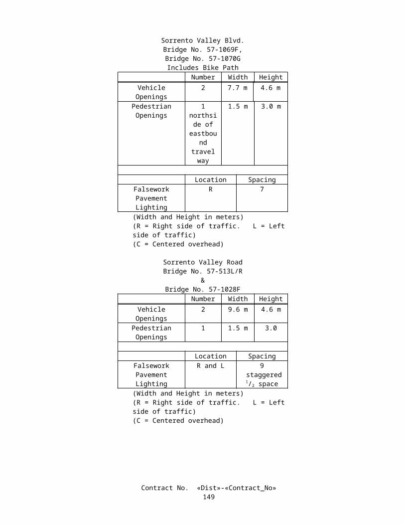
Portions of bridges to be removed are briefly described as follows:
LOCATION ACARMEL MOUNTAIN ROAD UNDERCROSSING
Bridge No. 57-0314L/RRemove barrier railing and portions of bridge deck overhang, abutment, and wingwall as shown on the plans.
LOCATION BLOS PENASQUITOS CREEK BRIDGE
Bridge No. 57-0511L/RRemove barrier railing and portions of bridge deck overhang and wingwall as shown on the plans.
LOCATION CROUTE 5/805 SEPARATION
Bridge No. 57-0512L/RRemove barrier railing and portions of bridge deck overhang, abutment, and wingwall as shown on the plans.
LOCATION DSORRENTO VALLEY VIADUCT
Bridge No. 57-0513L/RRemove barrier railing and portions of bridge deck overhang, abutment, and wingwall as shown on the plans.
The following additional requirements apply to the removal of portions of bridges whenever the removal work is to be performed over public traffic or railroad property:
A. A protective cover supported by falsework or members of the existing structure shall be constructed before beginning bridge removal work.
B. The construction and removal of the protective cover and the installation and removal of temporary railings shall conform to the requirements under "Order of Work" "Maintaining Traffic" and "Temporary Railings" of these special provisions.
C. The protective cover shall prevent any materials, equipment, or debris from falling onto the public traffic or railroad property. The protective cover shall have a minimum strength equivalent to that provided by good, sound Douglas fir planking having a nominal thickness of 50 mm. Additional layers of material shall be furnished as necessary to prevent fine materials or debris from sifting down upon the traveled way and shoulders.
D. The protective cover shall conform to the provisions for falsework in Section 51-1.06, "Falsework," of the Standard Specifications.
E. The Contractor shall be responsible for designing and constructing a safe and adequate protective cover, and shoring and falsework needed to support the protective cover, all with sufficient strength and rigidity to support the entire load to be imposed.
F. Bridge removal methods shall be described in the working drawings and calculations in sufficient detail to substantiate live loads used in the protective cover design. Dead and live load values assumed for designing the protective cover shall be shown on the working drawings.
G. At locations where the bridge railing is to be removed, the protective cover shall extend from the face of the exterior girder or at least 0.6-m inside of the bridge railing to be removed, whichever is less, to at least 1.2 m beyond the outside face of the bridge railing.
H. During the removal of bridge segments, and when portions of the bridge, such as deck slabs or box girder slabs, comply with the requirements for the protective cover, a separate protective cover need not be constructed.
I. Before removal, the protective cover shall be cleaned of all debris and fine material.J. The protective cover shall provide the openings specified under "Maintaining Traffic" of these special provisions,
except that when no openings are specified for bridge removal a vertical opening of 4.6 m and a horizontal opening of 9.8 m shall be provided for the passage of public traffic.
K. The protective cover shall provide the minimum clearances as required under "Relations with Railroad Company" of these special provisions for the passage of railroad traffic.
L. The construction of the protective cover as specified herein shall not relieve the Contractor of responsibilities specified in Section 7-1.12A, "Indemnification," and Section 7-1.12B, "Insurance," of the Standard Specifications.
Contract No. «Dist»-«Contract_No»152

10-1.34 CLEARING AND GRUBBINGClearing and grubbing shall conform to the provisions in Section 16, "Clearing and Grubbing," of the Standard
Specifications and these special provisions.Vegetation shall be cleared and grubbed only within the excavation and embankment slope lines.At locations where there is no grading adjacent to a bridge or other structure, clearing and grubbing of vegetation shall
be limited to 1.5 m outside the physical limits of the bridge or structure.Existing vegetation outside the areas to be cleared and grubbed shall be protected from injury or damage resulting from
the Contractor's operations.Activities controlled by the Contractor, except cleanup or other required work, shall be confined within the graded areas
of the roadway.Nothing herein shall be construed as relieving the Contractor of the Contractor's responsibility for final cleanup of the
highway as provided in Section 4-1.02, "Final Cleaning Up," of the Standard Specifications.
10-1.35 WATERINGDeveloping a water supply and applying watering shall conform to the provisions in Section 17, "Watering," of the
Standard Specifications and these special provisions.Attention is directed to the source or sources of water for use on the project specified in the "Materials Information"
handout available to the contractors.Attention is directed to "Beginning of Work, Time of Completion and Liquidated Damages" of these special provisions
regarding availability of water.
10-1.36 EARTHWORKEarthwork shall conform to the provisions in Section 19, "Earthwork," of the Standard Specifications and these special
provisions.Isolation casing backfill shall be slurry cement backfill conforming to the provisions of Section 19-3.062, "Slurry
Cement Backfill", of the Standard Specifications.Roadway embankment, as shown on the plans, for retaining walls 466, 470 and 527 shall conform to the provisions in
Section 19-3.06, "Structure Backfill," of the Standard Specifications and these special provisions.Structure backfill placed for retaining walls 466, 470 and 527 shall be compacted to a relative compaction of 95 percent.At the location and to the limits shown on the plans for foundation treatment, material below the bottom of retaining wall
footing, shall be removed and replaced with structure backfill. The relative compaction shall not be less than 95 percent. Removal of the material will be measured and paid for as structure excavation (retaining wall) and furnishing, placing and compacting the replacement material will be measured and paid for as structure backfill (retaining wall).
Surplus excavated material not designated or determined to contain aerially deposited lead shall become the property of the Contractor and shall be disposed of outside the highway right of way in conformance with the provisions in Section 7-1.13, "Disposal of Material Outside the Highway Right of Way," of the Standard Specifications.
Where a portion of the existing surfacing is to be removed, the outline of the area to be removed shall be cut on a neat line with a power-driven saw to a minimum depth of 50 mm before removing the surfacing. Full compensation for cutting the existing surfacing shall be considered as included in the contract price paid per cubic meter for roadway excavation and no additional compensation will be allowed therefor.
Settlement periods are required for the bridge approach embankments at the bridges listed in the following table.At the bridge bents listed in the following table, excavation for the footings, drilling holes for cast-in-place piles, or
driving the foundation piles at each location shall not be done until the expiration of the settlement period for the embankment at the adjacent abutment of the same structure or an adjacent structure.
Carmel Mountain Road UCBridge No. 57-0314L/RAbutment Number Settlement Period, Days
1 Up to 304 Up to 30
Contract No. «Dist»-«Contract_No»153
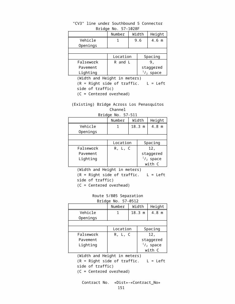
Carmel Mountain Road UCBridge No. 57-0314SAbutment Number Settlement Period, Days
1 302 30
Bridge over Los Penasquitos CreekBridge No. 57-0511
Abutment Number Settlement Period, Days
1, left side widening Up to 1804, left side widening Up to 180
RTE. 5/805 SeparationBridge No. 57-0512
Abutment Number Settlement Period, Days
5, left wingwall Up to 906, right side widening Up to 90
Sorrento Valley ViaductBridge No. 57-0513R/LAbutment Number Settlement Period, Days
1, Left Bridge, left widen 608, right widen Up to 1809, left widen Up to 180
SB 5 Truck ConnectorBridge No. 57-1028FAbutment Number Settlement Period, Days
12 30
S5/S805 Truck ConnectorBridge No. 57-1069FAbutment Number Settlement Period, Days
1 12021 60
N805/N5 Truck ConnectorBridge No. 57-1070GAbutment Number Settlement Period, Days
1 1809 90
Surcharge embankments shall be constructed above the grading plane where listed in the following table.
Contract No. «Dist»-«Contract_No»154

Roadway SurchargeStations 14+00.000 to 15+80.000
&Stations 19+72.000 to 20+58.000
Surcharge Height, Meters Settlement Period, Days
4.0 180
Earth Retaining Structure Number 466
Surcharge Height, Meters Settlement Period, Days
2 270
Earth Retaining Structure Number 470
Surcharge Height, Meters Settlement Period, Days
N/A 270
Earth Retaining Structure Number 527
Surcharge Height, Meters Settlement Period, Days
N/A 270
The duration of the required settlement period at each location, when the settlement period is 60 days or less, will be determined by the Engineer and will not exceed the number of days listed in the tables of settlement data.
The duration of the required settlement period at each location when the settlement period exceeds 60 days will be determined by the Engineer. The estimated duration of the settlement periods are listed in the tables of settlement data. The Engineer may order an increase or decrease in any estimated settlement period. An ordered increase or decrease in any settlement period will result in an increase or decrease in the number of working days allowed for the completion of the work if the settlement period involved is considered to be the current controlling operation in conformance with the provisions in Section 8-1.06, "Time of Completion," of the Standard Specifications. Neither the Contractor nor the State will be entitled to any compensation other than an adjustment of contract time due to increases or decreases in the settlement periods.
The removal of surplus embankment material placed as a surcharge embankment, including material removed to conform to the finished slope lines shown on the plans, will be paid for at the contract price per cubic meter for roadway excavation.
No backfill material shall be deposited against the back of Type 6 retaining walls until the grout has developed a strength of not less than 10 MPa in compression or until the grout has been in place for 28 days, whichever occurs first.
Geocomposite drain shall conform to the details shown on the plans and the following:
A. Attention is directed to "Engineering Fabrics" under "Materials" of these special provisions.B. Geocomposite drain shall consist of a manufactured core not less than 6.35 mm thick nor more than 50 mm thick
with one or both sides covered with a layer of filter fabric that will provide a drainage void. The drain shall produce a flow rate, through the drainage void, of at least 25 liters per minute per meter of width at a hydraulic gradient of 1.0 and a minimum externally applied pressure of 168 kPa.
C. A Certificate of Compliance conforming to the provisions in Section 6-1.07, "Certificates of Compliance," of the Standard Specifications shall be furnished for the geocomposite drain certifying that the drain produces the required flow rate and complies with these special provisions. The Certificate of Compliance shall be accompanied by a flow capability graph for the geocomposite drain showing flow rates for externally applied pressures and hydraulic gradients. The flow capability graph shall be stamped with the verification of an independent testing laboratory.
D. Filter fabric for the geocomposite drain shall conform to the provisions for fabric for underdrains in Section 88, "Engineering Fabrics," of the Standard Specifications.
Contract No. «Dist»-«Contract_No»155

E. The manufactured core shall be either a preformed grid of embossed plastic, a mat of random shapes of plastic fibers, a drainage net consisting of a uniform pattern of polymeric strands forming 2 sets of continuous flow channels, or a system of plastic pillars and interconnections forming a semirigid mat.
F. The core material and filter fabric shall be capable of maintaining the drainage void for the entire height of geocomposite drain. Filter fabric shall be integrally bonded to the side of the core material with the drainage void. Core material manufactured from impermeable plastic sheeting having nonconnecting corrugations shall be placed with the corrugations approximately perpendicular to the drainage collection system.
G. The geocomposite drain shall be installed with the drainage void and the filter fabric facing the embankment. The fabric facing the embankment side shall overlap a minimum of 75 mm at all joints and wrap around the exterior edges a minimum of 75 mm beyond the exterior edge. If additional fabric is needed to provide overlap at joints and wrap-around at edges, the added fabric shall overlap the fabric on the geocomposite drain at least 150 mm and be attached thereto.
H. Should the fabric on the geocomposite drain be torn or punctured, the damaged section shall be replaced completely or repaired by placing a piece of fabric that is large enough to cover the damaged area and provide a minimum 150-mm overlap.
I. Plastic pipe shall conform to the provisions for edge drain pipe and edge drain outlets in Section 68-3, "Edge Drains," of the Standard Specifications.
J. Treated permeable base to be placed around the slotted plastic pipe at the bottom of the geocomposite drain shall be cement treated permeable base conforming to the provisions for cement treated permeable base in Section 29, "Treated Permeable Bases," of the Standard Specifications and these special provisions.
K. The treated permeable base shall be enclosed with a high density polyethylene sheet or PVC geomembrane, not less than 250 µm thick, which is bonded with a suitable adhesive to the concrete and geocomposite drain. Surfaces to receive the polyethylene sheet shall be cleaned before applying the adhesive. The treated permeable base shall be compacted with a vibrating shoe type compactor.
If structure excavation or structure backfill involved in bridges is not otherwise designated by type, and payment for the structure excavation or structure backfill has not otherwise been provided for in the Standard Specifications or these special provisions, the structure excavation or structure backfill will be paid for at the contract price per cubic meter for structure excavation (bridge) or structure backfill (bridge).
Structure excavation designated as (Type D), for footings at the locations shown on the plans, will be measured and paid for by the cubic meter as structure excavation (Type D). Ground water or surface water is expected to be encountered at these locations, but seal course concrete is not shown or specified. Structure excavation for footings at locations not designated on the plans as structure excavation (Type D), and where ground or surface water is encountered, will be measured and paid for by the cubic meter as structure excavation (bridge).
The contract price paid per cubic meter for isolation casing backfill shall include full compensation for furnishing all labor, materials, tools, equipment, and incidentals, and for doing all the work involved in isolation casing backfill, complete in place, as shown on the plans, as specified in the Standard Specifications and these special provisions, and as directed by the Engineer.
10-1.37 CONTROLLED LOW STRENGTH MATERIALControlled low strength material shall consist of a workable mixture of aggregate, cementitious materials, and water and
shall conform to the provisions for slurry cement backfill in Section 19-3.062, "Slurry Cement Backfill," of the Standard Specifications and these special provisions.
At the option of the Contractor, controlled low strength material may be used as structure backfill for pipe culverts, except that controlled low strength material shall not be used as structure backfill for aluminum and aluminum-coated culverts nor for culverts having a diameter or span greater than 6.1 m.
When controlled low strength material is used for structure backfill, the width of the excavation shown on the plans may be reduced so that the clear distance between the outside of the pipe and the side of the excavation, on each side of the pipe, is a minimum of 300 mm. This minimum may be reduced to 150 mm when the height of cover is less than or equal to 6.1 m or the pipe diameter or span is less than 1050 mm.
Controlled low strength material in new construction shall not be permanently placed higher than the basement soil. For trenches in existing pavements, permanent placement shall be no higher than the bottom of the existing pavement permeable drainage layer. If a drainage layer does not exist, permanent placement in existing pavements shall be no higher than 25 mm below the bottom of the existing asphalt concrete surfacing or no higher than the top of base below the existing portland cement concrete pavement. The minimum height that controlled low strength material shall be placed, relative to the culvert invert, is 0.5 diameter or 0.5 height for rigid culverts and 0.7 diameter or 0.7 height for flexible culverts.
Contract No. «Dist»-«Contract_No»156

When controlled low strength material is proposed for use, the Contractor shall submit a mix design and test data to the Engineer for approval prior to excavating the trench for which controlled low strength material is proposed for use. The test data and mix design shall provide for the following:
A. A 28-day compressive strength between 345 kPa and 690 kPa for pipe culverts having a height of cover of 6.1 m or less and a minimum 28-day compressive strength of 690 kPa for pipe culverts having a height of cover greater than 6.1 m. Compressive strength shall be determined in conformance with the requirements in ASTM Designation: D 4832.
B. When controlled low strength material is used as structure backfill for pipe culverts, the sections of pipe culvert in contact with the controlled low strength material shall conform to the requirements of Chapter 850 of the Highway Design Manual using the minimum resistivity, pH, chloride content, and sulfate content of the hardened controlled low strength material. Minimum resistivity and pH shall be determined in conformance with the requirements of California Test 643. The chloride content shall be determined in conformance with the requirements of California Test 422 and the sulfate content shall be determined in conformance with the requirements of California Test 417.
C. Cement shall be any type of portland cement conforming to the requirements in ASTM Designation: C 150; or any type of blended hydraulic cement conforming to the requirements in ASTM Designation: C 595M or the physical requirements in ASTM Designation: C 1157M. Testing of cement will not be required.
D. Admixtures may be used in conformance with the provisions in Section 90-4, "Admixtures," of the Standard Specifications. Chemical admixtures containing chlorides as Cl in excess of one percent by mass of admixture, as determined in conformance with the requirements of California Test 415, shall not be used. If an air-entraining admixture is used, the maximum air content shall be limited to 20 percent. Mineral admixtures shall be used at the Contractor's option.
Materials for controlled low strength material shall be thoroughly machine-mixed in a pugmill, rotary drum or other approved mixer. Mixing shall continue until the cementitious material and water are thoroughly dispersed throughout the material. Controlled low strength material shall be placed in the work within 3 hours after introduction of the cement to the aggregates.
When controlled low strength material is to be placed within the traveled way or otherwise to be covered by paving or embankment materials, the material shall achieve a maximum indentation diameter of 76 mm prior to covering and opening to public traffic. Penetration resistance shall be measured in conformance with the requirements in ASTM Designation: D 6024.
Controlled low strength material used as structure backfill for pipe culverts will be considered structure backfill for compensation purposes.
10-1.38 MATERIAL CONTAINING AERIALLY DEPOSITED LEADEarthwork involving materials containing aerially deposited lead shall conform to the provisions in "Earthwork" and this
section "Material Containing Aerially Deposited Lead" of these special provisions.Attention is directed to "Aerially Deposited Lead" of these special provisions.Type Y material contains aerially deposited lead in average concentrations greater than or equal to 5.0 mg/L Soluble
Lead and between 0 - 350 mg/kg (inclusive) Total Lead, as tested using the California Waste Extraction Test. Type Y material exists between 0.0 m and 6.0 m, measured horizontally from the edges of existing pavement, from Station 518+72.79 to Station 519+05.887 "SD" Line southbound, from Station 530+62.000 to Station 544+20.000 "SD" Line southbound, and from Station 563+40.000 to Station 574+13.674 "SD" Line southbound, and from Station 519+05.888 to Station 522+66.743 "SDL" Line southbound, from Station 525+20.000 to Station 526+20.000 "SDL" Line southbound, and from Station 527+00.000 to Station 530+62.000 "SDL", southbound, and from Station 510+67.687 to Station 519+05.887 "SD" Line, northbound, and from Station 534+68.000 to Station 544+00.000 "SD" Line northbound, and from Station 524+60.000 to Station 525+60.000 "SDR" Line northbound, and from Station 527+20.000 to Station534+68.000 "SDR" Line and from a depth of 0.0 m to 0.6 m below existing grade, or as shown on the plans. These materials shall be placed as shown on the plans, unless otherwise directed by the Engineer, and covered with a minimum 0.3-m layer of non-hazardous soil or pavement. These materials are hazardous waste regulated by the State of California that may be reused as permitted under the Variance of the Department of Toxic Substances Control. Temporary surplus material may be generated on this project due to the requirements of stage construction. Temporary surplus material shall not be transported outside the project limits. In order to conform to the requirements of these provisions, it may be necessary to stockpile materials for subsequent stages or construct some embankments out of stage or handle temporary surplus material more than once.
Contract No. «Dist»-«Contract_No»157

LEAD COMPLIANCE PLANThe Contractor shall prepare a project specific Lead Compliance Plan to prevent or minimize worker exposure to lead
while handling material containing aerially deposited lead. Attention is directed to Title 8, California Code of Regulations, Section 1532.1, “Lead,” for specific Cal-OSHA requirements when working with lead.
The Lead Compliance Plan shall contain the elements listed in Title 8, California Code of Regulations, Section 1532.1(e)(2)(B). Before submission to the Engineer, the Lead Compliance Plan shall be approved by an Industrial Hygienist certified in Comprehensive Practice by the American Board of Industrial Hygiene. The Plan shall be submitted to the Engineer for review and acceptance at least 15 days prior to beginning work in areas containing aerially deposited lead.
The Lead Compliance Plan shall include perimeter air monitoring incorporating upwind and downwind locations as shown on the plans or as approved by the Engineer. Monitoring shall be by personal air samplers using National Institute of Safety and Health (NIOSH) Method 7082. Sampling shall achieve a detection limit of 0.05µg/m3 of air per day. Daily monitoring shall take place while the Contractor clears and grubs and performs earthwork operations. A single representative daily sample shall be analyzed for lead. Results shall be analyzed and provided to the Engineer within 24 hours. Average lead concentrations shall not exceed 1.5µg/m3 of air per day. If concentrations exceed this level the Contractor shall stop work and modify the work to prevent release of lead. Monitoring shall be done under the direction of and data reviewed by and signed by a Certified Industrial Hygienist.
The Contractor shall not work in areas containing aerially deposited lead within the project limits, unless authorized in writing by the Engineer, until the Engineer has accepted the Lead Compliance Plan.
Prior to performing work in areas containing aerially deposited lead, personnel who have no prior training or are not current in their training status, including State personnel, shall complete a safety training program provided by the Contractor. The safety training program shall meet the requirements of Title 8, California Code of Regulations, Section 1532.1, "Lead."
Personal protective equipment, training, and washing facilities required by the Contractor's Lead Compliance Plan shall be supplied to State personnel by the Contractor. The number of State personnel will be 5.
The Engineer will notify the Contractor of acceptance or rejection of any submitted or revised Lead Compliance Plan not more than 10 days after submittal of the plan.
The contract lump sum price paid for Lead Compliance Plan shall include full compensation for furnishing all labor, materials, tools, equipment, and incidentals and for doing all the work involved in preparing the Lead Compliance Plan, including paying the Certified Industrial Hygienist, and for providing personal protective equipment, training and medical surveillance, as specified in the Standard Specifications and these special provisions, and as directed by the Engineer.
EXCAVATION AND TRANSPORTATION PLANWithin 15 days after approval of the contract, the Contractor shall submit 3 copies of the Excavation and Transportation
Plan to the Engineer. The Engineer will have 7 days to review the Excavation and Transportation Plan. If revisions are required, as determined by the Engineer, the Contractor shall revise and resubmit the Excavation and Transportation Plan within 7 days of receipt of the Engineer's comments. The Engineer will have 3 days to review the revisions. Upon the Engineer's approval of the Excavation and Transportation Plan, 3 additional copies of the Excavation and Transportation Plan incorporating the required changes shall be submitted to the Engineer. Minor changes or clarifications to the initial submittal may be made and attached as amendments to the Excavation and Transportation Plan. In order to allow construction to proceed, the Engineer may conditionally approve the Excavation and Transportation Plan while minor revisions or amendments to the Plan are being completed.
The Contractor shall prepare a written, project specific Excavation and Transportation Plan establishing the procedures the Contractor will use to comply with requirements for excavating, transporting, and placing (or disposing) of material containing aerially deposited lead. The Excavation and Transportation Plan shall conform to the regulations of the Department of Toxic Substance Control and the California Division of Occupational Safety and Health Administration (Cal-OSHA). The sampling and analysis plans shall meet the requirements for the design and development of the sampling plan, statistical analysis, and reporting of test results contained in USEPA, SW 846, "Test Methods for Evaluating Solid Waste," Volume II: Field Manual Physical/Chemical, Chapter Nine, Section 9.1. The plan shall contain, but not be limited to the following elements:
A. Excavation schedule (by location and date)B. Temporary locations of stockpiled materialC. Sampling and analysis plans for areas after removal of a stockpile
1. Location and number of samples2. Analytical laboratory
D. Sampling and analysis plan for soil coverE. Sampling and analysis plan for post excavation from Station 518+72.79 to Station 519+05.887 "SD" Line
southbound, from Station 530+62.000 to Station 544+20.000 "SD" Line southbound, and from Station 563+40.000 Contract No. «Dist»-«Contract_No»
158

to Station 574+13.674 "SD" Line southbound, and from Station 519+05.888 to Station 522+66.743 "SDL" Line southbound, from Station 525+20.000 to Station 526+20.000 "SDL" Line southbound, and from Station 527+00.000 to Station 530+62.000 "SDL", southbound, and from Station 510+67.687 to Station 519+05.887 "SD" Line, northbound, and from Station 534+68.000 to Station 544+00.000 "SD" Line northbound, and from Station 524+60.000 to Station 525+60.000 "SDR" Line northbound, and from Station 527+20.000 to Station534+68.000 "SDR" Line as shown on the plans.
F. Dust control measuresG. Transportation equipment and routesH. Method for preventing spills and tracking material onto public roadsI. Truck waiting and staging areasJ. Example of Bill of Lading to be carried by trucks transporting Type Y material. The Bill of Lading shall contain:
US DOT description including shipping name, hazard class, and ID number; handling codes; quantity of material; volume of material. Copies of the bills of lading shall be provided to the Engineer upon placement of Type Y material in its final location. Trucks carrying Type Y material shall not leave the highway right of way.
K. Spill Contingency Plan for material containing aerially deposited lead
DUST CONTROLExcavation, transportation, placement, and handling of materials containing aerially deposited lead shall result in no
visible dust migration. The Contractor shall have a water truck or tank on the job site at all times while clearing and grubbing and performing earthwork operations in work areas containing aerially deposited lead.
Stockpiles of material containing aerially deposited lead shall not be placed where affected by surface run-on or run-off. Stockpiles shall be covered with plastic sheeting 0.33 mm minimum thickness or 0.3 m of non-hazardous material. Stockpiles shall not be placed in environmentally sensitive areas. Stockpiled material shall not enter storm drains, inlets, or waters of the State.
MATERIAL TRANSPORTATIONPrior to traveling on public roads, loose and extraneous material shall be removed from surfaces outside the cargo areas
of the transporting vehicles and the cargo shall be covered with tarpaulins, or other cover, as outlined in the approved Excavation and Transportation Plan. The Contractor shall be responsible for costs due to spillage of material containing lead during transport. The Department will not consider the Contractor a generator of these hazardous materials, and the Contractor will not be obligated for further cleanup, removal, or remedial action for such materials handled or disposed of in conformance with the requirements specified in these special provisions and the appropriate State and Federal laws and regulations and county and municipal ordinances and regulations regarding hazardous waste.
DISPOSALSurplus materials whose lead content is not known shall be analyzed for aerially deposited lead by the Contractor prior to
removing the materials from within the project limits. The Contractor shall submit a sampling and analysis plan and the name of the analytical laboratory to the Engineer at least 15 days prior to beginning sampling or analysis. The Contractor shall use a laboratory certified by the California Department of Health Services. Sampling shall be at a minimum rate of one sample for each 150 m3 of surplus material and tested for lead using EPA Method 6010 or 7000 series.
Sampling, analyses, and reporting of results for surplus materials not previously sampled will be paid for as extra work as provided in Section 4-1.03D, "Extra Work," of the Standard Specifications.
The Engineer will obtain the Environmental Protection Agency (EPA) Generator Identification Number for hazardous material disposal. The Engineer will sign all hazardous waste manifests. The Contractor shall notify the Engineer five days before the manifests are to be signed.
Sampling, analyzing, transporting, and disposing of materials containing aerially deposited lead excavated outside the pay limits of excavation will be at the Contractor’s expense.
MEASUREMENT AND PAYMENTQuantities of roadway excavation (aerially deposited lead) of the types shown in the Engineer's Estimate, will be
measured and paid for in the same manner specified for roadway excavation in Section 19, "Earthwork," of the Standard Specifications.
Full compensation for preparing an approved Excavation and Transportation Plan, transporting material containing aerially deposited lead reused in the work from location to location, and transporting and disposing of material containing aerially deposited lead shall be considered as included in the contract prices paid per cubic meter for the items of roadway excavation (aerially deposited lead) involved, and no additional compensation will be allowed therefor.
Contract No. «Dist»-«Contract_No»159

No payment for stockpiling of material containing aerially deposited lead will be made, unless the stockpiling is ordered by the Engineer.
10-1.39 PLANTABLE GEOSYNTHETIC REINFORCED WALLThis work shall consist of constructing geosynthetic reinforced wall with plantable concrete face as shown on the plans
and in conformance with the provisions in Section 19, “Earthwork,” and Section 51, “Concrete Structures,” of the Standard Specifications, the details shown on the plans, and these special provisions.
Drainage systems and other facilities shall be constructed in the geosynthetic reinforced embankment in conformance with the details shown on the plans and these special provisions.
MATERIALSGeosynthetic material
Geosynthetic reinforcement material shall consist of material designed for use in subsurface geotechnical slope reinforcement applications. Geosynthetic reinforcement material shall be geogrid material.
Geogrid material shall have a regular, defined open area pattern. Geogrid material shall provide pullout resistance from the soil by a combination of soils shearing friction on the plane surfaces parallel to the direction of shearing and soils bearing on transverse grid surfaces normal to the direction of grid movement. The percentage of the open area for geogrid material shall be between 50 and 90 percent of the surface area, including openings.
Geosynthetic reinforcement material shall conform to the following:
1 Long Term Design Strength (LTDS) for geosynthetic reinforcement material shall be equal to or greater than values shown on the plans or elsewhere in these special provisions as determined by Geosynthetic Research Institute (GRI) Test Methods. LTDS for geogrid reinforcement and geotextile reinforcement shall be determined by Standard Practice GRI GG4 (a) and (b) and GRI GT7, respectively. These values are minimum average roll values. Long Term Design Strength is the strength of the geogrid or the geotextile calculated by applying all partial factors of safety in accordance with GRI Standard Practice GG4 (a) and (b) or GT7, except that the product of the partial factors of safety for installation damage (based on a soil gradation possessing a D50 between 2.36 and 4.75 mm), chemical degradation, and biological degradation shall not be allowed as less than 1.30. The factor of safety for creep deformation shall be determined for a 75-year design life as determined by GRI GG4 (a) and (b) for geogrids or GRI GT7 for geotextiles. The 75-year design life strength is determined from the creep curve which becomes asymptotic to a constant strain line of 10 percent or less. In the absence of specific test data, the partial factor of safety default values (installation damage, creep deformation, chemical degradation, biological degradation, and joint) as indicated in the Standard Practice GRI GG4 (a) and (b) and GRI GT7 shall be applied to the calculations of the LTDS.
2 Long Term Design Strength (LTDS) for uniaxial geosynthetic reinforcement material shall be no less than the following values for each geogrid type:
Geogrid Type LTDS, kN/mType 1 45Type 2 32Type 3 25Type 4 17
3 Long Term Design Strength (LTDS) for biaxial geosynthetic material shall be no less than 4 kN/m in the direction of reinforcement.
4 Geosynthetic reinforcement material shall be resistant to naturally occurring alkaline and acidic soil conditions, and to attack by bacteria.
The test results used in the calculations of the LTDS shall be submitted to the Engineer not less than 15 working days prior to commencing geosynthetic reinforced embankment construction. The test results used in the calculations of the LTDS shall be prepared and signed by a Civil Engineer registered in the State of California.
Geosynthetic reinforcement material shall consist of high density polyethylene, polypropylene, high tenacity polyester encapsulated, or polyaramide and shall conform to the respective material requirements:
Contract No. «Dist»-«Contract_No»160

High Density PolyethyleneHigh density polyethylene (HDPE) geosynthetic reinforcement material shall be manufactured from high density
polyethylene conforming to the following:1. HDPE geosynthetic reinforcement material shall be manufactured from HDPE conforming to the requirements
of ASTM Designation: D 1248.2. HDPE geosynthetic reinforcement material shall have a LTDS in the primary strength direction of not less than
the values specified and identified herein and shown and identified on the plans. Biaxial geosynthetic reinforcement material shall have a LTDS in the reinforcement direction greater than or equal to the values specified in these special provisions.
PolypropylenePolypropylene geosynthetic reinforcement material shall be fabricated from polypropylene or high-density
polypropylene sheets conforming to the following:
1. Polypropylene shall conform to the requirements of ASTM Designation: D 4101, Group 1 Class 1 Grade 2.
2. Polypropylene shall have a LTDS in the primary strength direction of not less than the values specified and identified herein and shown and identified on the plans. Biaxial geosynthetic reinforcement material shall have a LTDS in the reinforcement direction greater than or equal to the values specified in these special provisions.
High Tenacity Polyester EncapsulatedHigh tenacity polyester encapsulated geosynthetic reinforcement material shall be manufactured from high tenacity
polyester yarn conforming to the following:
1. High tenacity polyester yarn shall conform to the requirements of ASTM Designation: D 629. In addition to conforming to the requirements for geosynthetic, geogrid, the material shall be encapsulated in an acrylic latex coating.
2. High tenacity polyester encapsulated geosynthetic reinforcement material shall have a LTDS in the primary strength direction of not less than the values specified and identified herein and shown and identified on the plans. Biaxial geosynthetic reinforcement material shall have a LTDS in the reinforcement direction greater than or equal to the values specified in these special provisions.
PolyaramidesPolyaramides geosynthetic reinforcement material shall be manufactured from polyaramide yarn conforming to the
following:
1. Polyaramides yarn shall conform to the requirements of ASTM Designation: D 629.
2. Polyaramides geosynthetic reinforcement material shall have a LTDS in the primary strength direction of not less than the values specified and identified herein and shown and identified on the plans. Biaxial geosynthetic reinforcement material shall have a LTDS in the reinforcement direction greater than or equal to the specified in these special provisions.
Unless otherwise shown on the plans, only one type of geosynthetic reinforcement material shall be used in the embankment construction.
Filter fabric, conforming to the provisions in Section 88, “Engineering Fabrics,” of the Standard Specifications, shall be placed in the geosynthetic reinforced embankment at the locations shown on the plans.
Geosynthetic reinforcement material and filter fabric shall be handled and stored in conformance with the manufacturer’s recommendations and these special provisions. Geosynthetic reinforcement material shall be furnished by the manufacturer in protective covers that shall protect the reinforcement material and filter fabric from ultraviolet radiation and from abrasion during shipping, handling and storage. All geosynthetic reinforcement material and filter fabric placed during a work shift shall be covered with embankment material during the same work shift.
A Certificate of Compliance for the geosynthetic reinforcement material and filter fabric used shall be furnished to the Engineer in conformance with the provisions in Section 6-1.07, "Certificates of Compliance."
Contract No. «Dist»-«Contract_No»161

Geocomposite Drain The geocomposite drain shall conform to the details shown on the plans and the requirements in these special provisions.Attention is directed to “Engineering Fabrics” under “Materials” elsewhere in these special provisions.Geocomposite drain shall consist of a manufactured core not less than 6.35 mm, nor more than 50 mm thick with both
sides covered with a layer of filter fabric that will provide a drainage void. The drain shall produce a flow rate, through the drainage void, of at least 25 liters per minute per meter of width at a hydraulic gradient of 1.0 and a minimum externally applied pressure of 450 kPa.
A Certificate of Compliance conforming to the provisions in Section 6-1.07, “Certificates of Compliance,” of the Standard Specifications shall be furnished for the geocomposite drain certifying that the drain produces the required flow rate and complies with these special provisions. The Certificate of Compliance shall be accompanied by a flow capability graph for the geocomposite drain showing flow rates for externally applied pressures and hydraulic gradients. The flow capability graph shall be stamped with the verification of an independent testing laboratory.
Filter fabric for the geocomposite drain shall conform to the provisions for fabric for underdrains in Section 88, “Engineering Fabrics,” of the Standard Specifications.
The manufactured core shall be either a preformed grid of embossed plastic, a mat of random shapes of plastic fibers, a drainage net consisting of a uniform pattern of polymeric strands forming 2 sets of continuous flow channels, or a system of plastic pillars and interconnections forming a semi-rigid mat.
The core material and filter fabric shall be capable of maintaining the drainage void for the entire height of geocomposite drain. Filter fabric shall enclose the core material with the drainage void.
The geocomposite drain shall be installed in accordance with the plans. Additional fabric is needed to provide at least 300-mm wrap-around at edges.
Should the fabric on the geocomposite drain be torn or punctured, the damaged section shall be replaced completely or repaired by placing a piece of fabric that is large enough to cover the damaged area and provide a 150-mm overlap.
UnderdrainsPerforated plastic pipe underdrains shall conform to the provisions in Section 68-1, “Underdrains,” of the Standard
Specifications. Solid outlet pipes shall conform to the provisions in Section 68-2, "Horizontal Drains", of the Standard Specifications.
EARTHWORKFill material for plantable geosynthetic reinforced wall shall consist of material excavated from within the project limits.
The material shall be free from organic material and substantially free of shale or other soft, poor durability particles; shall not contain recycled materials, such as glass, shredded tires, portland cement concrete rubble, asphaltic concrete rubble, or other unsuitable material as determined by the Engineer; and shall meet the following requirements:
Gradation RequirementsSieve Size Percentage Passing California Test
37.5 mm (1-1/2”) 100 20219 mm (3/4”) 95 – 100 2024.75 mm (#4) 30 – 100 202420 µm (#40) 20 – 95 20275 µm (#200) 0 – 75 202
5 µm 0 - 40 202
Property RequirementsTest Requirement California Test
Plasticity Index 20 max. 204pH 6 to 9 643
Imported borrow material from outside the project limits to be used as structure backfill for this structure shall conform to the provisions in Section 19-3.06, "Structure Backfill", of the Standard Specifications.
PRECAST CONCRETE WALL FACEConcrete wall face shall be constructed as shown on the approved shop plans and in conformance with the provisions in
Section 51, "Concrete Structures," of the Standard Specifications and these special provisions.
Contract No. «Dist»-«Contract_No»162

Wall face members shall consist of a series of precast reinforced concrete headers and stretchers. Precast concrete elements shall be colored in conformance with Section 72-6.03, "Materials" of the Standard Specifications to closely match Color No. 23531 of the Federal Standard 595B after curing and when air dry.
Reinforcing steel shall conform to the requirements in ASTM Designation: A 615, Grade 60, or A 706 and reinforcing wire shall conform to the requirements in ASTM Designation: A 496.
External vibration resulting in adequate consolidation may be used, at the option of the Contractor.Concrete test cylinders shall conform to the provisions in Section 90-9, "Compressive Strength," of the Standard
Specifications, except that when the penetration of fresh concrete is less than 25 mm, the concrete in the test mold shall be consolidated by vibrating the mold equivalent to the consolidating effort being used to consolidate the concrete in the members.
Wall face members shall be cured in conformance with the provisions for piles with a class designation ending in C (corrosion resistant) in Section 90-7.05, "Curing Precast Prestressed Concrete Piles," of the Standard Specifications.
The provisions in Section 51-1.18, "Surface Finishes," of the Standard Specifications shall not apply to wall face members.
When removed from the forms, the members shall present a true surface of even texture free from honeycombs and voids larger than 25 mm in diameter and 8 mm in depth.
All pockets that are larger than the voids described above shall be cleaned and filled with mortar as directed by the Engineer. Mortar shall conform to the provisions in Section 51-1.135, "Mortar," of the Standard Specifications.
If rock pockets are of the extent or character as to affect the strength of the member materially or to endanger the life of the steel reinforcement, as determined by the Engineer, the member shall be replaced by the Contractor at the Contractor's expense.
The members shall be handled in such a manner as to prevent breakage. Members that are damaged during handling and placing shall be removed and replaced with new members by the Contractor at the Contractor's expense.
Neoprene sheets shall conform to the provisions in Section 51-1.145, "Strip Waterstops", of the Standard Specifications.Elastomeric bearing pads shall conform to the provisions in "Elastomeric Bearing Pads" of these special provisions.Alignment pins shall be galvanized and conform to Section 75-1.03, "Miscellaneous Bridge Metal", of the Standard
Specifications.Precast concrete wall face shall be placed to the lines and grades established by the Engineer. The foundation for wall
face shall be excavated as shown on the plans and in conformance with the provisions in Section 19, "Earthwork," of the Standard Specifications. The foundation shall be approved by the Engineer before any precast concrete members are placed.
CONSTRUCTIONPlantable geosynthetic reinforced wall shall be constructed in layers. The loose thickness of each layer of embankment
material before compaction shall not exceed 0.3-m. Unless otherwise specified or shown on the plans, a relative compaction of not less than 95 percent shall be obtained in all material in the embankment. Surfaces to receive geosynthetic reinforcement material shall be compacted to a relative compaction of not less than 95 percent.
Surfaces to receive geosynthetic reinforcement material, immediately prior to placing, shall be free of loose or extraneous material and objects that may damage the geosynthetic reinforcement material during installation and embankment construction.
Geosynthetic reinforcement material shall be handled and placed in conformance with the manufacturer’s recommendations and these special provisions. The geosynthetic reinforcement material shall be laid horizontally at the elevation designated on the plans, on compacted embankment, from the front limit of geosynthetic reinforcement, with additional geosynthetic reinforcement length for wrapping and overlapping, to the required embedment. The geosynthetic reinforcement material shall be placed wrinkle free, pulled taut, aligned, and anchored before embankment material is placed on it. Slack in geosynthetic reinforcement material shall be removed before embankment material is placed on it. Geosynthetic reinforcement material shall be installed in horizontal planes at the intervals, elevations, and for minimum embedment lengths shown on the plans. Each layer of geosynthetic reinforcement material shall not vary more than 0.15 -m from the horizontal plane established for that layer of reinforcement, for the entire width and length of the reinforcement.
Each layer of geosynthetic reinforcement material shall be placed on the compacted embankment to form a continuous mat. Overlapping and splicing geosynthetic reinforcement material shall conform to the following:
A. Uniaxial geogrid may be placed without overlaps along edges parallel to the direction of working tensile strength. Uniaxial geogrid shall not be overlapped along edges perpendicular to the direction of working tensile strength.
B. Sections of uniaxial geogrid reinforcement may be joined with mechanical connectors recommended by the geosynthetic reinforcement material manufacturer. Splices in the reinforcement material shall not be placed vertically within 2 m of the front limit of geosynthetic reinforcement, within 2 m of the top of the wall, nor within 1.2 m, measured horizontally and vertically, to another joint. Each length of geogrid reinforcement material shall
Contract No. «Dist»-«Contract_No»163

not contain more than one splice joint. Splice joints shall be made for the full width of each reinforcement strip by using similar materials with similar strength, and connection devises supplied or recommended by the reinforcement material manufacturer. Joints in geogrid shall be pulled and held taut during embankment material placement.
Geosynthetic reinforcement material shall be placed in such a manner that the direction of maximum strength is oriented perpendicular to the wall alignment. Each layer of reinforcement material shall be placed on the embankment material to form a continuous mat. Adjacent strips of geosynthetic reinforcement material placed in this manner need not be overlapped.
At locations where wall structures and underground structures intersect geosynthetic reinforcement material, the geosynthetic reinforcement material shall be trimmed around the structures, as shown on the plans or as directed by the Engineer.
Geosynthetic reinforcement material shall be secured in place with staples, pins, sand bags, or embankment material as required to prevent the displacement of the geosynthetic reinforcement material during placement of additional reinforcement material and embankment construction.
Geosynthetic reinforcement material shall not extend into the pavement structural section.A layer of embankment material not less than 0.15-m in thickness shall be maintained between the geosynthetic
reinforcement material and the compaction equipment. Equipment and vehicles shall not be operated directly on the geosynthetic reinforcement material, except as provided herein.
During spreading and compacting of the embankment material, rubber tired vehicles may be driven directly on geosynthetic reinforcement material, provided the traffic is part of the embankment material placement operation and does not damage or displace the geosynthetic reinforcement material. The amount of traffic repetitions shall be kept to a minimum. The speed of the equipment operating on the geosynthetic reinforcement material shall not exceed 6 mph at any time, turning and sudden braking of the vehicle shall not be permitted. Damaged areas of geosynthetic reinforcement material shall be replaced or repaired immediately in conformance with these special provisions.
Tracked construction equipment shall not be operated directly on the geosynthetic reinforcement material. A layer of embankment material not less than 0.20-m in thickness shall be maintained between the geosynthetic reinforcement material and the tracked construction equipment. Turning of tracked construction equipment shall be kept to a minimum to prevent tracks from displacing the fill material or the geosynthetic reinforcement material.
Geosynthetic reinforcement material damaged during construction operations shall be repaired or replaced at the Contractor’s expense. Damaged areas of reinforcement may be repaired by placing additional geosynthetic reinforcement material over the damaged areas in conformance with the following overlap requirements:
Edges of geogrid perpendicular to wall layout line shall overlap by the smaller of 6 apertures or 0.20-m. Edges of geogrid parallel to wall layout line shall be joined using mechanical connections conforming to the provisions of these special provisions.
Filter fabric shall be installed, at the locations shown on the plans, in conformance with the provisions in Section 68-1.03, “Installing Underdrains,” of the Standard Specifications.
At locations where compaction is accomplished with hand operated equipment, fill shall be placed in horizontal layers not more than 0.15 m in uncompacted thickness. Only hand-operated equipment shall be allowed within 1 m of the front limit of geosynthetic reinforcement and underground structures.
Fill material shall be placed from the middle of the reinforced zone towards the ends of the geosynthetic reinforcement to provide further tensioning.
At the end of each workshift, fill material shall be graded away from the slope crest to prevent ponding of water on surface of the reinforced soil mass. Site shall be maintained to prevent the flow of water from overtopping slope crest during construction and after completion of slope. At the start of each workshift, the Contractor shall consolidate newly placed lifts with previously compacted fill material.
Uniaxial geogrid shall be cut next to the cross machine direction bar. The cross machine direction bar shall be placed at the front limit of geosynthetic reinforcement.
A minimum of 75 mm of compacted fill material shall be required between layers of geosynthetic reinforcement layers, unless shown otherwise on the plans.
The concrete headers and stretchers shall be interlocked and assembled as shown on the approved shop plans.
RESEARCH ACTIVITIESThe Engineer will conduct research instrumentation within the limits of the Plantable Geosynthetic Reinforced Wall,
Bridge No. 57-1075.Research activities will consist of installation of 20 vertical slope indicators, 30 horizontal slope indicators, and 30 sets
of 6-point extensometers, 30 pressure cells, 30 strain gauge, 30 pneumatic settlement cells, 20 vibrating-wire piezometers, 50 survey reference points, and an on-site data acquisition monitoring system.
All instruments will be installed at 5 different wall stations. Vertical slope indicators will be installed after completion of the wall. These research devices will be State-furnished and installed by the State forces.
Contract No. «Dist»-«Contract_No»164

The installation of research devices will be scheduled in advance with the Contractor. The Contractor shall thereupon schedule the construction operations so as not to interfere with installation, surveying, or reading of the instruments. It is anticipated that the installation of research devices can be scheduled so that the Contractor’s operations will not be delayed nor interfered with.
All instrumentation shall be protected by the Contractor and shall be replaced at the Contractor’s expense if damaged by Contractor’s operations. No traffic or equipment shall be allowed to pass over any part of the instrumentation until that part is covered by a minimum of 0.5 m of hand-compacted fill.
Installation of research equipment by the Contractor’s forces, as required, will be paid for as extra work as provided in Section 4-1.03D of the Standard Specifications.
In the event that the Contractor’s operations are delayed or interfered with by reason of the installation, protection or State force’s use of the research and monitoring equipment, the State will compensate the Contractor for such delays to the extent provided in Section 8-1.09, “Right of Way Delays,” of the Standard Specifications, and not otherwise, except as provided in Section 8-1.10, “Utility and Non-Highway Facilities,” of the Standard Specifications.
MEASUREMENTThe quantity of plantable geosynthetic reinforced wall to be measured and paid for shall be by the square meter of face
area constructed (elevation view).
PAYMENTThe contract price paid per square meter for plantable geosynthetic reinforced wall shall include full compensation for
furnishing all labor, materials, tools, equipment, and incidentals, and for doing all the work involved in constructing geosynthetic reinforced wall, complete in place, including geosynthetic reinforcement material, structure excavation and backfill, filter fabric, geocomposite drain, subdrains, precast concrete headers and stretchers, bearing pads, as shown on the plans, as specified in the Standard Specifications and these special provisions, and as directed by the Engineer.
10-1.40 STONE COLUMNSGround improvement and densification by dry, bottom-feed vibro-displacement stone columns shall conform to the
details shown on the plans, specified in these special provisions and as directed by the Engineer.The ground improvement and densification shall extend to the top of the competent soils or rocks and the refusal criteria
specified in these special provisions, or otherwise approved by the Engineer.Foundation recommendations are included in the "Information Handout" available to the Contractor as provided for in
Section 2-1.03, "Examination of Plans, Specifications, Contract, and Site of Work," of the Standard Specifications. Attention is directed to “Order of Work” and “Obstructions” elsewhere in these special provisions. Attention is directed
to Section 7-1.11, “Preservation of Property,” of the Standard Specifications regarding damage from soil densification operations to existing utilities, improvements and facilities.
The Contractor shall review the soil subsurface information provided. Additional subsurface information is available for viewing at the Transportation Laboratory. The soil information provided represents existing conditions at the specific boring locations at the time the borings were performed.
Difficult stone column installation is anticipated due to the presence of groundwater, sporadic cobbles and gravels, interfingering layers of alluvial materials, subsurface concrete debris, underground utilities, overhead utilities, sound control, vibration monitoring, and traffic control.
The Contractor may provide an alternative stone column plan meeting the minimum requirements of (1) refusal criteria of stone columns, (2) densificiation criteria based on cone penetration tests, and (3) area replacement ratio specified in these special provisions. The alternative plan shall be submitted as an attachment to the Pre-construction submittal for approval by the Engineer.
MATERIALSVibro-displacement stone column in-fill shall consist of hard, durable, angular, clean crushed rock, and shall be free
from clay lumps, cementation, organic material, and other deleterious substances. Stone column in-fill shall have a Durability Index of not less than 40 in accordance with California Test Method 229 and shall conform to the following grading limits:
Contract No. «Dist»-«Contract_No»165
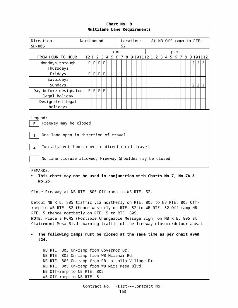
Sieve Sizes Percent Passing by Weight38.1 mm (1-1/2 in) 100
25.4 mm (1 in) 80 - 10019 mm (3/4 in) 60 – 85
12.7 mm (1/2 in) 40 – 609.5 mm (3/8 in) 25 – 454.75 mm (No. 4) 5 – 152.36 mm (No. 8) 0 – 5
The sieve designations for the gradation limits are to conform to the ASTM Standards (ASTM C-136). Specific gravity and unit weight of stone column in-fill will be determined by California Test Methods 206 and 212, respectively.
The Contractor shall supply the Engineer with a sample of the vibro-displacement stone column in-fill material no less than 15 working days before the start of work. The sample shall be representative of the proposed vibro-displacement stone column in-fill material, and shall be a minimum of 50 kg.
Drainage blanket shall be constructed and placed as shown on the plans. Fill material encased in the drainage blanket shall be Class 1, Type B permeable material conforming to the provisions in Section 68-1.025, "Permeable Material", of the Standard Specifications. Fill material shall be compacted to a relative compaction of not less than 95 percent. Filter fabric shall conform to the provisions in Section 88, “Engineering Fabrics,” of the Standard Specifications. Geogrid material shall conform to the provisions in "Plantable Geosynthetic Reinforced Wall" of these special provisions.
CONSTRUCTIONVibro-displacement stone column construction shall be carried out by a Contractor having experience in the supervision
and execution of ground improvement and densification by vibro-displacement stone column techniques.All vibro-displacement stone column work shall be under the direct control of skilled personnel in the employ of the
Contractor and experienced in the use of the equipment. On-site supervisors shall have a minimum two-year experience in vibro-displacement stone column, and equipment operators shall have a minimum one-year experience in vibro-displacement stone column construction. The Contractor shall submit a list identifying the on-site supervisors and equipment operators who will be assigned to the project. The list shall contain a summary of each individual’s experience.
The Contractor shall submit, for review by the Engineer, a statement of the previous work experience similar to that described in these special provisions. The statement shall include at least 10 successful vibro-displacement stone column projects within past five years. This statement shall include a written description of each project, owner’s contact name and current phone number, the dates and the extent of the work, the manner of its execution, and any other information that supports the Contractor’s ability to carry out the work described in these special provisions.
EquipmentThe vibrating probes shall be of the bottom feed type and shall be rated by the manufacturer to provide at least 150
horsepower and 25 metric ton of horizontal force and designed to penetrate the soil vertically to the required depths. The vibrating probes and equipment required for the work shall be in good working order and shall be adequate to densify the soils in accordance with the specified acceptance criteria at the design spacing and to the depths required.
Pre-construction SubmittalsThe Pre-construction submittal for approval of the Engineer shall contain as a minimum:
A. Type of vibro-displacement equipment to be used including dimensions, horsepower and maximum amperage rating.
B. Type of crane including expected boom length and maximum operating height.
C. Access grading plan with any additional erosion control items noted.
D. Working drawings showing the construction sequence and layout of number-identified stone column, stone column diameter, and proposed cone penetration test locations.
E. Sample of stone column in-fill material or certified test results.
F. Ground movement, vibration, and noise control plans. Ground movement, vibration and noise monitoring plans.
Contract No. «Dist»-«Contract_No»166

G. Anticipated maximum and average discharge wastewater flows from the subgrade improvement work.
H. Erosion and sedimentation control procedures in the access grading plan.
The listed submittals and other additional submittals shall conform to the requirements in Section 5-1.02, “Plans and Working Drawings,” of the Standard Specifications and these special provisions.
Test AreasTo evaluate and to facilitate refinement of the method, equipment, and procedure to be used by the Contractor and
provide an initial assessment of the stone column performance, before production work, the Contractor shall install stone columns at 2 test areas at locations specified by the Engineer. The test area shall be about 15 m by 12 m and shall use production stone column locations. The stone columns shall be installed in accordance with the plans at each test area location.
At each test area, 8 cone penetration tests before stone column installation and 8 cone penetration tests after stone columns installation shall be performed at locations selected by the Engineer and centered between stone columns to the installed stone column depths. Cone penetration tests shall be performed in accordance with ASTM Designation: D-3441 and shall be performed by cone penetration equipment that is capable of penetrating the soil vertically to the required stone column depths.
The Contractor shall submit the data from cone penetration tests and the Engineer shall be allowed 5working days to review the test data. If the densification criteria is met, the test area will be approved. The Contractor shall then submit the stone column post-test submittal, including the construction method, procedure, sequence, and stone column refusal criteria to the Engineer for approval. The Contractor shall allow the Engineer 10 working days to review the post-test submittal. If the data from the cone penetration tests indicate that the densification criteria has not been achieved, the Contractor shall revise the densification method or layout and submit the revised method and additional testing program to the Engineer for approval.
Stone Column RequirementsThe Contractor shall not use water jet to aid the advance of the vibrating probe or assist the installation of the stone
column. After penetration to the full treatment depth, the vibrating probe shall be slowly retrieved in 0.3 to 0.45 m increments to allow in-fill placement. The vibrating probe shall be re-driven several times through each increment into a recently treated depth interval to observe amperage build up.
Vibro-displacement stone columns shall be constructed at a maximum spacing of 2.4 m center to center in an equilateral triangular pattern or as shown on the approved plans, unless otherwise approved by the Engineer. The diameter of vibro-displacement stone columns at any depth shall be no less than 1.1 m and shall be increased where necessary to achieve the required criteria. The specified minimum stone column diameter and maximum center-to-center spacing is to achieve a minimum area replacement ratio of 0.19. The area replacement ratio is calculated as the area of a stone column to the tributary area of a single stone column.
Contractor shall facilitate automated real-time data collection and monitoring systems to record and monitor vibration energy and stone column volume as a function of depth in each column. The systems shall be operational to the satisfaction of the Engineer prior to beginning the installation of stone columns and shall be operational throughout the construction of stone columns on each stone column work station used. The systems, as a minimum, shall monitor and record continuous depth of probe in meters of:
Power consumption of vibrating probe (Amperage), or other equipment-specific parameters which are measures of penetration resistance and densification; and
Volume of processed in-fill material and stone column diameter in metric units.
The Contractor shall provide to the Engineer an electronic copy of the data and a graphic printout of the key parameters as part of the daily log of each stone column construction. The daily log shall be delivered to the Engineer the next working day. The recorded data and graphic printout log shall identify the date, name, location, equipment used, and the equipment operators.
Verification TestingVerification that the specified densification has been improved and achieved shall be determined following treatment of
initial test column areas and at regular intervals thereafter by the Contractor. Cone penetration test method, performed in accordance with ASTM Designation: D-3441, shall be used for verification testing. Cone penetration tests shall be
Contract No. «Dist»-«Contract_No»167

performed by cone penetration equipment that are capable of penetrating the soil vertically to the stone column tip elevation shown on the plans.
A comparing set of two cone penetration tests, one before the stone column installation and the other after the stone column installation, shall be performed for each 144 square meters of stone column area respectively to monitor the magnitude of soil improvement by stone columns. Locations of cone penetration tests within each comparing set shall be placed no more than 3 m apart. Each cone penetration test shall be centered between a group of 3 or 4 adjacent stone columns that are arranged in a pattern similar to the corner of a polygon with nearly equal sides. The location of cone penetration tests shall be approved by the Engineer and shall be recorded on the as-built layout plan.
One cone penetration test shall be performed for each 288 square meters of stone column area after stone column installation, at random locations identified by the Engineer during the construction. Additional cone penetration test locations and cone penetration tests may be required as directed by the Engineer.
Compensation for additional cone penetration tests ordered by the Engineer will be paid for as extra work as provided in Section 4-1.03D of the Standard Specifications.
In cone penetration tests, cone tip resistance, qc; sleeve friction, fs; and pore water pressure, U; shall be measured at 50 mm depth increments, or less, throughout the length of the test probes.
Corrected cone tip resistance will be calculated using the following formula:
qT = qc + (1-a)*ubt
a = d2/D2
whereqT is normalized cone tip resistance, MPaqc is cone tip resistance, MPad is diameter of load cell support, mD is diameter of cone, mubt is pore water pressure reading behind the cone tip, MPa, measured at depth increments of 50 mm or less
The minimum corrected qT value as measured in the center of any equilateral triangle formed by the stone column pattern, shall be no less than 8 MPa. The average cone tip resistance values over a 1.5-m depth interval shall be no less than 10.5 MPa.
All strata, seams, lenses or pockets of soils exhibiting a Soil Behavior Type Index, I c, greater than 2.95 will not be included in the calculation of the average corrected cone tip resistance. The Soil Behavior Type Index, Ic, shall be calculated based on the formula presented by Jefferies and Davies in the paper “Estimation of SPT N values from the CPT” ASTM, 1993.
If the cone penetration tests indicate the specified criteria have not been met, the Contractor shall perform additional cone penetration tests, as directed by the Engineer, to define the limits of the area of failing to meet the criteria. Additional stone columns shall be installed in areas in which the specified criteria are not met. Additional stone columns shall be centered between groups of 3 or 4 already installed stone columns. Additional cone penetration tests required by the Engineer will be paid for as extra work as provided in Section 4-1.03D of the Standard Specifications.
Layout and SchedulingThe Contractor shall accurately set out the compaction points at the site, in accordance with the plans or approved
construction drawings. The Contractor shall locate and construct the stone columns with a deviation not to exceed 100 mm from the positions shown on the plans or on the approved Contractor’s alternative plans. The Contractor shall be responsible for all required construction layout, surveying and staking.
Vibration, Ground Movement, and Noise Control and MonitoringThe Contractor shall take precautions to prevent vibration and ground movement from the vibro-displacement work
from interfering with or damaging neighboring properties or buildings. The Contractor shall submit vibration, ground movement, and noise control and monitoring plans as a part of the Pre-construction submittal for the Engineer’s approval and install the monitoring systems according to the approved plan. Ground movement shall not exceed 20 mm at 1 m outside soil-cement mixing area. The Contractor shall monitor ground movement, ground vibrations, and noise level during the operation of the vibro-displacement equipment and monitor ground movement throughout the duration of the construction.
When ground vibrations, movements or noise from vibro-displacement work adversely affect the project and neighboring properties and buildings, the Engineer may direct the Contractor to use alternative methods or procedures of stone column construction. Alternate methods shall be subject to the prior approval of the Engineer but shall remain the responsibility of the Contractor.
Contract No. «Dist»-«Contract_No»168

Addition or Deletion of Stone ColumnsBased on the results of the verification testing and subject to the discretion of the Engineer, stone columns in addition to
or deleted from those indicated on the approved shop plans may be required to achieve ground improvement requirements. The Engineer will advise the Contractor as to the location and depth of any additional or deleted stone columns. With the possible exception of the area replacement ratio criteria, the construction of the additional stone columns shall be in accordance with these special provisions. If the approved shop plans are the Contractor's alternative plan, the Contractor shall determine the location and depth of any additional or deleted stone columns and submit the changes to the Engineer for approval.
Following verification testing of the initial test pattern of stone columns, to achieve the specified densification criteria, the Contractor may be required to adjust the construction methodologies or the spacing or the arrangement of the stone columns. Additions to or deletions from the total number of stone columns may also be required.
Heave or collapse of the ground surface at the work site may result from the densification effort and stone column construction. Restoration of the area of treatment and adjoining areas that affected by the Work to the working surface grade shall be the responsibility of the Contractor, unless otherwise approved by the Engineer.
All cavities, depressions, and irregularities, resulting from the Contractor’s activities, shall be repaired by grading and compacting the area to match the surrounding terrain.
Predrilling of overburden, hard strata and pavement and structural section will be permitted. Holes predrilled through overburden shall be backfilled with stone column in-fill. Pavement and structural section shall be replaced in kind.
The cost of such site cleaning and restoration shall be considered incidental to the prices bid for the work in this Contract, and no additional payment will be made.
RecordsThe Contractor shall maintain the following field records for each stone column vibro-displacement :
Identification and location;
Date and time required for completion;
Elevation of the ground surface immediately before and after completion;
Elevation of and depth to the lowest penetration level of the probe;
Quantity of stone used per lineal meter of each stone column;
Maximum vibration energy (indicated by electrical current output) vs. depth throughout the entire duration of each vibro-displacement process; and
The Contractor shall maintain daily field records of the following:
A. Any unusual conditions encountered.
B. Monitored vibration, ground movement, and noise levels.
The Contractor shall provide the Engineer with a copy of all the field records at the next day of production, for all of the stone columns installed on the previous day.
WastewaterWastewater from the subgrade improvement and construction operations shall not be permitted to enter local drainage
systems or wetlands All surface runoff and water from dewatering operations shall be captured and conveyed to the storm water detention and treatment sites. No direct discharge to adjacent drainage systems or surrounding wetlands will be allowed.
Silty material and other debris washed out of the soil during the densification process shall be disposed of as provided in Section 19-2.06, "Surplus Material" of the Standard Specifications.
Contract No. «Dist»-«Contract_No»169

MEASUREMENT AND PAYMENTStone columns, including stone columns in test areas, will be measured and paid for by the meter of stone column of the
sizes listed in the Engineer's estimate incorporated into the accepted work. The quantity to be paid for shall be the depth of stone column installed between the top and bottom elevations of the stone columns as shown on the approved plans.
The contract price paid per meter for stone column shall include full compensation for furnishing all materials, labor, tools, equipment and incidentals and for doing all the work involved in ground improvement and densification, complete in place, including drainage blanket, monitoring, and drilling and backfilling for predrilled holes, as shown on the Plans, as specified in these special provisions, and as directed by the Engineer.
Full compensation for cone penetration test shall be considered as included in the contract price paid per meter for stone column of the sizes listed in the Engineer's estimate and no additional compensation will be allowed therefor.
10-1.41 SOIL-CEMENTThis work shall consist of furnishing and installing soil-cement by deep mixing at the locations shown on the plans.Deep soil-cement mixing shall be performed by mixing in-situ soil with cement grout to form a uniform mixture,
blended thoroughly and evenly by controlled methods.Foundation recommendations are included in the "Information Handout" available to the Contractor as provided for in
Section 2-1.03, "Examination of Plans, Specifications, Contract, and Site of Work," of the Standard Specifications.Attention is directed to “Order of Work” and “Obstructions” elsewhere in these special provisions. Attention is directed
to Section 7-1.11, “Preservation of Property,” of the Standard Specifications regarding damage soil densification operations to existing utilities, improvements and facilities.
Additional subsurface information is available for viewing at the Transportation Laboratory. The foundation information represents existing conditions at the specific boring locations at the time the borings were performed.
Difficult soil-cement installation is anticipated due to the presence of embedment requirements into rock, groundwater, sporadic cobbles and gravels, interfingering layers of alluvial materials, subsurface concrete debris, underground utilities, overhead utilities, sound control, vibration monitoring, and traffic control.
Installation of soil-cement by deep mixing auger methods shall create soil-cement structures to improve strength properties of the foundation soils for the plantable geosynthetic reinforced wall above.
The Contractor shall confirm that the installed soil-cement achieves the required compressive strength and ensure that it is installed in the design configuration and within the specified limits.
The ground improvement shall extend to 1 m below the top of the competent soils or rocks, or otherwise approved by the Engineer. The estimated elevations of the top of competent soils or rocks are shown in the plans.
Soil-cement mixing equipment shall be capable of advancing through previously installed and cured soil-cement.
DEEP-MIXINGDeep soil-cement mixing shall improve strength properties of foundation soils within the area shown on the plans. Soil-
cement elements shall be placed in a uniformly distributed regular pattern to achieve 50% area ratio, the ratio of each soil-cement element plan area to the plan tributary area of the soil-cement element. The soil-cement mixing patterns shall produce discrete soil-cement elements that will not inhibit free flow of groundwater. The average 56-day unconfined compressive strength of soil-cement throughout the depth of each soil-cement element shall be no less than 2,000 kPa.
The Contractor may provide an alternative plan meeting the minimum performance requirement specified herein. The alternative plan shall be submitted as an attachment to the pre-construction submittal for approval by the Engineer.
The Contractor shall conduct a Pre-Production (PPC) Program within the limits of soil-cement areas shown on the plans prior to commencing soil-cement mixing to establish production parameters, procedures, and materials to be used during the production phase.
The PPC Program shall produce soil-cement mix design and procedures for production mixing based upon the information provided from the PPC Program including: estimated in-situ 28-day and 56-day compressive strength of the soil-cement, cement-grout injection pressure and rates, mixing rotational speeds, penetration and withdrawal rates of the mixing tools, and mixing times at bottom of the soil-cement element when there is no vertical movement of the mixing tools, and complete description of all mixing operations.
SUBMITTALSThe submittals and other additional submittals shall conform to the requirements in Section 5-1.02, “Plans and Working
Drawings,” of the Standard Specifications and these special provisions, and shall be stamped by a California Registered Professional Civil Engineer.
Submittals shall be stamped by a California Registered Professional Civil Engineer except for survey data which shall be stamped by a California Registered Professional Civil Engineer or a California Registered Land Surveyor.
Contract No. «Dist»-«Contract_No»170

The Contractor shall submit, for review by the Engineer, a statement of the previous work experience similar to that described in these special provisions. The statement shall include at least 10 successful vibro-displacement stone column projects within past five years. This statement shall include a written description of each project, owner’s contact name and current phone number, the dates and the extent of the work, the manner of its execution, and any other information that supports the Contractor’s ability to carry out the work described in these special provisions.
Pre-construction SubmittalsAt least four weeks prior to commencement of any mobilization of deep soil-cement mixing equipment for production
mixing, the Contractor shall submit the following to the Engineer:
A. Names and qualifications of the soil-cement mixing personnel and surveyors, including project experience, resumes and other documentation that demonstrate the experience of the project engineers, field superintendents, rig operators, and batchplant operators for the deep soil-cement mixing.
B. A list of Contractors, responsible engineers, project descriptions and personnel responsibilities from soil-cement mixing projects completed by the soil-cement mixing Project Engineers and Field Superintendents during the past ten years. Contractor's names, addresses and telephone numbers shall be included for these projects representing the individuals comparable experience. The projects listed to demonstrate personnel qualifications shall have employed equipment using similar auger configuration(s) as proposed for the work of this Contract.
C. Submit data on equipment to be used for the deep soil-cement mixing, proportioning, pumping, injecting and mixing soil-cement as wells as all other ancillary equipment, including equipment capable of remixing non-conforming soil-cement.
D. Spoil containment (sheet piling or other) structures and methods to be used to prevent the migration or leakage of spoil return, disturbed in-situ soils or other spoil material beyond the immediate limits of soil-cement mixing operations. The Contractor shall demonstrate that the containment structure is stable under loads applied by soil-cement, water, in-situ soils, overlying fill materials, construction equipment, other surcharge loads and loads applied by the subsequent deep mixing operations. Include also details and methods to be used to collect and dispose of the spoil return and other spoil materials.
E. Sequence and time schedule of all operations including plan location and sequence of all deep soil-cement mixing. The Contractor shall submit a soil-cement element Layout Plan based on the limits shown on the Plans to achieve the required plan area configurations and coverage and necessary overlaps and auger re-penetrations over the depths and limits shown on the Plans. Plan locations of all proposed soil-cement mixing shall be shown on Layout Plans of suitable scale to clearly show the details of the layout. Soil-cement elements on the Layout Plans shall be numbered and dimensioned.
F. Cement grout mix design including: cement type, cement source, cement compound composition, water-cement ratio by weight and other pertinent details. Limit water- cement ratio to (1:1 maximum), unless otherwise demonstrated in the Pre-Production (PPC) Program specified in these special provisions.
G. The results of the PPC Program including, but not limited to: estimated in-situ 28-day and 56-day compressive strength of the soil-cement, cement-grout injection pressure and rates, mixing rotational speeds, penetration and withdrawal rates of the mixing tools, and mixing times at bottom of the soil-cement element when there is no vertical movement of the mixing tools, and complete description of all mixing operations.
H. Description of Quality Control Plan for deep soil-cement mixing including, but not limited to, the following:
1. A detailed description of the Quality Control Plan to be undertaken each day during soil-cement mixing to confirm that the installed soil-cement conforms to the required compressive strengths and unit weights specified, the plan area coverage over the required depths and limits, and required horizontal and vertical alignments.
2. Details of procedures to obtain soil-cement samples, catalog cuts of the soil- cement sampling device and curing boxes.
Contract No. «Dist»-«Contract_No»171

3. Measures to be implemented each day during soil-cement mixing to continuously monitor, modify and control: water-cement ratios; cement-grout injection pressures and quantities; mixing rotational speeds; penetration and withdrawal rates of the mixing equipment; horizontal and vertical alignments of the soil- cement elements; and other related aspects of the soil-cement mixing process.
4. Example formats of Daily Production Reports conforming to the requirements stated herein.
I. Proposed details and formats of all required tabular and graphical data presentations to be submitted to the Engineer during the course of the Work.
Construction Submittals Within two working days after the completion of each soil-cement element, submit the following:
1. Deviations of the center coordinates from the layout plan to the nearest 75 mm at the top of the element.
2. Vertical alignment profiles shall be submitted in accordance with the frequencies specified to the nearest 13 mm over the measurement length along axes parallel and perpendicular to the line of longitudinal progression; the elevation to the nearest 30 mm of the top and bottom of the element.
Within one working day after the end of a work shift, submit Daily Production Reports for the work shift to the Engineer. Daily Production Reports shall be filled out, checked for correctness, and signed by the Deep Soil Mixing Contractor’s field superintendent and the Contractor's field superintendent at the end of every work shift. The reports shall contain, but not be limited, to the following information:
1. Day, month, year, time of work, shift, beginning and end; names of each superintendent in charge of the Work for both the soil-cement mixing firm and the Contractor; a list of all workers' names associated with each soil-cement mixing machine; and a summary of equipment used during the shift.
2. The location and "neat" limits as shown on the Working Drawings of each completed soil-cement element installed during the work shift and all soil-cement elements completed to date, on a plan of suitable scale to clearly detail the locations of the elements.
3. Time of day of beginning and completion of each soil-cement element installed during the work shift.
4. Water-cement ratios, cement type, brand, and cement grout injection pressures and rates, mixing rotational speeds, penetration and withdrawal rates of the mixing equipment, batch plant production records, and installation sequence for every soil- cement element.
5. Other pertinent observations including, but not limited to; spoil returns, cement grout escapes, ground settlement and/or heave, collapses of the soil-cement element, advancement rates of the mixing equipment, and any unusual behavior of any equipment during the soil-cement mixing process and other noteworthy events. In the event of any Contractor claim, the Daily Production Reports shall be the primary documents to substantiate the reasons and basis for the claim.
6. Date, time, plan location, sample designation and elevation, and other details of soil- cement sampling.
7. Summary of any downtime or unproductive time, including start and end time, duration, and reason.
Within five weeks after completion of the deep soil-cement mixing, the Contractor shall submit survey data including:
1. A final Layout Plan of suitable scales showing the locations of each soil-cement element at the top of the element.
2. A tabular summary of layout center coordinates modified to reflect any measured- deviations of each soil-cement element at the top of the element, the elevation of the top and bottom of each element.
3. A compilation of all vertical alignment profiles.
Contract No. «Dist»-«Contract_No»172

SOIL-CEMENT QUALITY CONTROLThe Contractor shall verify that the installed soil-cement elements conform to these special provisions.The Contractor shall obtain soil-cement samples, including fluid and core samples, and provide them to the Engineer.
The Engineer will form preserve, cure, transport, and test the samples and report the test results. The Contractor shall coordinate sampling activities and Soil-Cement Quality Control with the Engineer. The Contractor shall supply incidental items, access, inside storage space, curing boxes and electrical power to the curing boxes. The Contractor shall supply molds for use in forming the samples.
Wet Grab Soil-Cement SamplesA minimum of two in-situ sampling rounds shall be performed daily at locations selected by the Engineer. The
Contractor shall obtain sampling rounds at the same soil-cement element, which shall consist of non-cured soil-cement samples from three depths selected by the Engineer. The Contractor shall obtain up to 20 additional wet grab sample test rounds as directed by the Engineer.
Separate soil-cement samples shall be retrieved within 60 minutes of the completion of the soil-cement column. The device used to retrieve the wet grab soil-cement samples shall be capable of obtaining a discrete fluid sample of soil-cement at a depth determined by the Engineer and shall be capable of accepting particles not thoroughly mixed that are up to 150 mm in dimension. The sampler shall be lowered empty, air only, to the required depth in the soil-cement element and then opened. Once filled with the soil-cement the sampler shall be closed to exclude entry or loss of soil- cement and shall be expeditiously raised to ground surface.
Each retrieved soil-cement sample shall be of sufficient volume to produce a minimum of six full cylinders, 150 mm diameter by 300 mm. The Contractor shall separate and retain all soil-cement retrieved from each depth. The Contractor shall then cut all retrieved particles of soil larger than 25 mm into smaller pieces that will pass a 25 mm sieve, and then immediately form the six cylinders with material passing through a 25 mm sieve, including particles of soil that were cut up.
Soil-cement samples shall be formed, cured and preserved in accordance with AASHTO T 23 and protected from freezing and extreme weather conditions which could have deleterious effect, at all times.
The Contractor may obtain additional samples and perform additional testing for his or her own information, at the Contractor's expense.
If the Contractor cannot obtain all of the required wet grab samples of the soil-cement in the designated soil-cement element, the Contractor shall obtain a full round of wet grab samples from the next soil-cement element installed by that rig. Continue taking wet grab samples in subsequent soil-cement elements until a full round is obtained.
From each sampling round, one cylinder from each sampling depth shall be used to determine the cement factor based on the cement content determined in accordance with AASHTO Specification T 144 (or ASTM D 806). Unless otherwise directed by the Engineer, for each soil-cement element, the Contractor shall test one cylinder at 7 days, one cylinder at 14 days, two cylinders at 28 days, and two cylinders at 56 days for unconfined compressive strength in accordance with ASTM Designation: D 2166. Submit the laboratory test results to the Engineer in accordance with these special provisions. Submit 3 cylinders from each of the three depths sampled for each soil-cement element to the Engineer.
Wet Grab Soil Cement Sample Sampling and Testing ScheduleFrequency Quantity Note
Number of sampling rounds (soil-cement elements)
Per day 2 At soil-cement elements determined by the Engineer
Number of wet grab soil-cement samples
Per soil-cement element
3 At depths determined by the Engineer
Number of cylinders Per wet-grab soil-cement
sample
6 150 mm diameter x 300 mm high cylinder
Total cylinders Per sampling round
18 (6 x 3)
Number of cylinders for test of cement factor and cement content
Per sampling round
3 At each of the 3 sampling depths
Number of cylinders for unconfined compressive strength test
Per sampling round
6 Test one at 7 days, one at 14 days, two at 28 days, and two at 56 days
Number of cylinders shall be submitted to the Engineer
Per sampling round
9 3 at each of the 3 sampling depths
Contract No. «Dist»-«Contract_No»173

Core SamplesCore samples shall be taken by the Contractor, for the purpose of obtaining and testing in-situ samples to evaluate
compressive strength, unit weight, vertical alignment, and composition of the soil-cement. Coring of soil-cement shall be performed in accordance with AASHTO T 225 and the requirements stated herein.
Continuous core samples of soil-cement elements shall be obtained at up to 25 separate locations selected by the Engineer and over the entire depth of the soil-cement. The samples shall be obtained using a PQ-size triple tube core barrel with a side discharge.
Immediately after retrieving the soil-cement core samples from a specific boring, wrap preserve and submit to the Engineer seven core samples per boring selected by the Engineer for subsequent evaluation and testing. Grout and completely fill the borehole after coring with cement mixture, minimum unconfined compressive strength of 2000 kPa, designed by the Contractor and approved by the Engineer.
Remaining core samples shall be boxed, stored, preserved and delivered. Core samples shall be protected from freezing and extreme weather conditions at all time.
If recovered core samples from any boring provide less than 90% recovery, or less than 50% RQD, or fewer than two intact cores of length more than 200 mm, in each core run, the Engineer may direct the Contractor to drill up to 2 additional borings and recover additional core samples for testing. If the samples from either of these additional borings do not provide required recovery, this process shall be repeated until coring provides required samples. These additional borings and core sampling shall be performed at the Contractor's expense.
Vertical Alignment ProfilesThe Contractor shall obtain vertical alignment profiles for one soil-cement element per day and shall advise the Engineer
within one hour after measuring the vertical alignment profile, of any non-compliance with tolerance requirements. The Contractor shall, at the direction of the Engineer, obtain and submit up to three additional vertical alignment profiles per day.
VIBRATION, GROUND MOVEMENT, AND NOISEThe Contractor shall not damage existing structures and services by excessive vibration, by inducing vertical or lateral
ground movements beneath or adjacent to them, by the rise or fall of groundwater levels, or by the off -site discharge of unacceptable waste water and/or sediment.
The Contractor shall take precautions such that vibration from the vibro-displacement work will not cause undue interference or damage to neighboring properties or buildings.
If, in the opinion of the Engineer, ground vibrations, movements or noise from soil-cement mixing work adversely affect the project and neighboring properties and buildings, the Engineer may direct the Contractor to use alternative methods or procedures of soil-cement mixing construction. Alternate methods shall be subject to the prior approval of the Engineer but shall remain the responsibility of the Contractor.
CEMENT GROUTCement shall conform to AASHTO M85, Type II, and shall be as specified in the submitted cement grout mix design
approved by the Engineer. Slag cement or fly ash shall not be allowed without the approval of the Engineer and submission of test data by the Contractor, which confirm no deleterious impact to the soil-cement.
Measure, handle, transport and store bulk cement in accordance with the manufacturer's recommendations. Cement packaged in cloth or paper bags shall be sealed within plastic or rubber vapor barriers.
Store cement to prevent damage by moisture. Material that has become caked due to moisture absorption shall not be used. Bags of cement shall be stacked no more than ten bags high to avoid compaction. Cement containing lumps or foreign matter of a nature and in amounts that may be deleterious to the grouting operations shall not be used.
Tricalcium aluminate content shall not exceed 8 percent.Water used in soil-cement and cement grout mixing and all other applications shall be potable, clean, of neutral pH and
free from sewage, oil, acid, alkali, salts, organic materials and other contamination.Cement grout shall be a stable homogeneous mixture of cement and water. The ratios of the components shall be
included in the pre-construction submittal. Cement grout composition shall not change throughout the soil-cement mixing unless requested in writing by the Contractor and approved in writing by the Engineer.
SOIL-CEMENTSoil-cement shall be a stable, uniform mixture of cement grout and the in-situ soils. The properties listed below shall be
verified in conformance with the approved Soil-cement Quality submittal.The ratios of various soil-cement components shall be proposed by the Contractor or as approved in the pre-construction
submittal subject to review by the Engineer. The Contractor shall adjust the mix design throughout the course of the Work in
Contract No. «Dist»-«Contract_No»174

order to achieve the required compressive strengths and total unit weights. The Contractor shall submit changes in the mix design or cement factor and obtain the Engineer's approval prior to implementing these changes.
Soil-cement obtained from wet grab samples shall conform to the following minimum compressive strength requirements. Unconfined compressive strength testing shall be performed in accordance with ASTM Designation: D-2166:
1. Soil-cement shall achieve a 56-day unconfined compressive strength of f’c no less than 1,800 kPa.
2. The average 56-day unconfined compressive strength within each soil-cement element shall be no less than 2,000 kPa.
The total unit weight of soil-cement samples shall be measured and shall be at least 21 kN/m3 or as determined and approved by the Engineer based on the result of approved PPC submittal. For each test round the average total unit weight of all soil-cement samples within the round will be calculated. If the average total weight from any two consecutive test rounds is less than 20 kN/m3, or a value determined and approved by the Engineer based on the result of approved PPC submittal, the Contractor shall adjust its mix as necessary to achieve the required unit weight.
Conformance with soil-cement uniformity criteria will be determined by the Engineer by evaluation of core samples. The soil-cement shall contain soil fragments with a maximum dimension not to exceed 1/4 of the diameter of the auger or 300 mm whichever is smaller. In addition, seventy percent of the depth cored shall have a minimum core sample 56-day unconfined compressive strength of 2000 kPa.
CONSTRUCTION The Contractor shall provide on-site project engineers during deep mixing soil-cement operations. The project engineers
shall be experienced in work comparable to that described herein, and having at least five full years experience as full time responsible Project Engineers, within the past ten years, in deep soil-cement mixing. Experience as full time Project Engineer within the last ten years shall include at least two projects, each of which had installations of at least 7,500 cubic meters of soil-cement to depths exceeding 25 meters and which required mixing in cohesive soils to create soil-cement structures similar to those required on this project.
Field Superintendents shall be present continuously on site, each shift of operation. The Field Superintendents shall each have at least three years accumulated experience with soil-cement techniques similar to the techniques in the approved PPC submittal; including at least two projects, one of which within the past five years requiring deep mixing in cohesive soils similar to this project.
Soil-cement mixing rig operators shall have accumulated a minimum of one year experience with soil-cement mixing technique and a minimum 200 hours of operating time on the soil-cement mixing rig under the direct supervision of the Field Superintendent and equipment manufacturer representative.
Grout mixing plant operators shall have a minimum 3 years experience in operating computer based cement grout mixing batch plants similar to the cement grout mixing batch plants in the approved PPC submittal.
Equipment shall have devices to permit accurate and continuous monitoring and control of: water-cement ratios, cement-grout injection pressures and quantities, mixing rotational speeds, advancement and withdrawal rates of the mixing tools, and other operations required to install and mix the soil-cement.
The soil-cement mixing machines shall be of sufficient size, capacity, torque, and capable of performing deep mixing to the required depths shown on the plans. The soil-cement mixing machine shall be capable of advancing and withdrawing the mixing tools while simultaneously injecting cement-grout and mixing in-situ soils.
Deep soil-cement mixing equipment shall use single or multiple-shaft mixing equipment with multiple auger centers configured in one straight line. Shafts shall uniformly inject cement grout at the bottom of the assembly. Mixing equipment shall be capable of advancing through previously installed and hardened soil-cement. Continuous flight augers longer than 1.5 m are not allowed. Auger flights and mixing paddles on a shaft shall extend to the full diameter of the element being formed, and shall have discontinuous lengths and be spaced to overlap with paddles of adjacent shafts in order to thoroughly break up the in-situ soils and blend them with injected cement grout to form a homogeneous mixture. If used to breakup and blend in-situ soil and cement grout, high-pressure jets shall not be directed radially to extend beyond the perimeter of the auger flights. Air shall not be injected into the in-situ soils.
Within 14 days after receiving the Engineer's notification of PPC approval and authorization to proceed with deep soil-cement mixing, the Contractor may begin substantive deep soil-cement mixing activities.
Installation of Soil-CementSoil-cement mixing shall be installed in uniformly distributed regular patterns and arrangements to achieve the minimum
area ratio, the ratio of each soil-cement element to its tributary area, of 50% within the soil-cement mixing areas as shown on the approved plans, and with soil-cement elements conforming to the alignment tolerances and required compressive strength and unit weights stated herein.
Contract No. «Dist»-«Contract_No»175

Soil-cement elements shall be installed with the equipment, materials, and procedures in the approved PPC submittal. The Contractor shall adjust the mix design, as necessary, throughout the course of the work in order to achieve the required compressive strength and total unit weight. The Contractor shall submit changes in the mix design to the Engineer for the review and approval prior to implementing the changes.
Soil-cement elements shall penetrate through the soft silty clay and loose silty sand alluvial deposit materials and key into the competent soil or rock by no less than 1 m and no more than 2 m. The estimated elevations of top of competent soil or rock are shown on the plans.
During soil-cement mixing, grout shall be introduced only by injecting cement grout through the bottom of the operating mixing equipment. Grout shall be introduced during the initial penetration of the augers, or during subsequent downstrokes of the augers, for the entire depth of the elements.
After final grouting of the soil-cement element, the Contractor shall obtain samples of in-situ soil-cement samples in accordance with the locations and frequencies in "Soil-Cement Quality" of these special provisions.
Water, debris or spoil material shall not be dumped or otherwise allowed to enter the soil-cement element.Any soil cement element which exhibits partial or total instability, shall be backfilled with cement grout and be remixed
full depth, at the Contractor's expense. Among other possibilities, signs of instability which could be observed during construction could include excess flow of grout from the hole, settlement of ground, and squeezing in on the drill rods.
Horizontal and Vertical Alignment TolerancesThe maximum horizontal deviation of the as-installed center of any soil-cement element at the ground surface or mudline
installation level shall not exceed 75 mm from the layout center coordinate, shown on the approved Contractor's submittal.The measured vertical alignment of soil-cement elements shall not deviate in any direction more than two percent from
vertical of the measured length, or be inclined more than two percent from vertical anywhere along the measured length.At the direction of the Engineer, any soil-cement elements which exceeds the allowable horizontal or vertical alignment
tolerances shall be re-mixed or supplemented with one or more adjacent or overlapping elements, at no additional cost to Caltrans.
ObstructionsWhere obstructions are encountered during deep soil-cement mixing, the Contractor shall remove the obstruction or
install additional soil-cement to encapsulate the obstruction, at the direction of the Engineer. If such conditions are encountered, the Contractor shall notify the Engineer in writing, and provide all pertinent information relating to the nature, depth, plan location coordinates, expected extent of the obstruction, and proposed procedures to overcome the obstruction. Such construction to overcome an unknown obstruction shall only be performed with the written authorization of the Engineer, and will be paid for as extra work as provided in Section 4-1.03D of the Standard Specifications.
The Contractor may elect to remove geological hindrances, install soil cement by an alternate soil-cement mixing pattern that avoids or encapsulates the hindrance but that achieves the required soil-cement area ratio, subject to the approval of the Engineer.
Containment, Collection and Disposal of Spoil ReturnAt all times during and at completion of soil-cement mixing operations, the site shall be maintained cleared of all debris
and water. Spoil return and other spoil material shall be piped or channeled to holding ponds, tanks, or other retention structures or facilities. The Contractor shall remove and dispose of all waste materials in accordance with the provisions in Section 7-1.13, "Disposal of Material Outside the Highway Right of Way," of the Standard Specifications.
All soil-cement collection, containment and disposal methods shall be thoroughly explained and shown on Working Drawings in the Contractor's submittals to the Engineer prior to the start of deep soil-cement mixing. The Contractor shall incorporate and be responsible for all sedimentation and turbidity control measures required by applicable federal, state and local regulations.
The Contractor shall take all necessary precautions and implement measures to prevent any spoil return, other spoil material or stockpiled materials from entering storm drain structures, drainage courses and other utility lines or from leaving the site via surface runoff. The Contractor shall prevent the migration of spoil return, spoil material or stockpiled materials into any surface water body, beyond the immediate limits of soil-cement mixing operations.
MEASUREMENTSoil-cement will be measured by the cubic meter. The quantity of soil-cement to be paid for shall be the quantity of
cement furnished to be mixed with the in-situ soil within the soil-cement area shown on the plans.
Contract No. «Dist»-«Contract_No»176
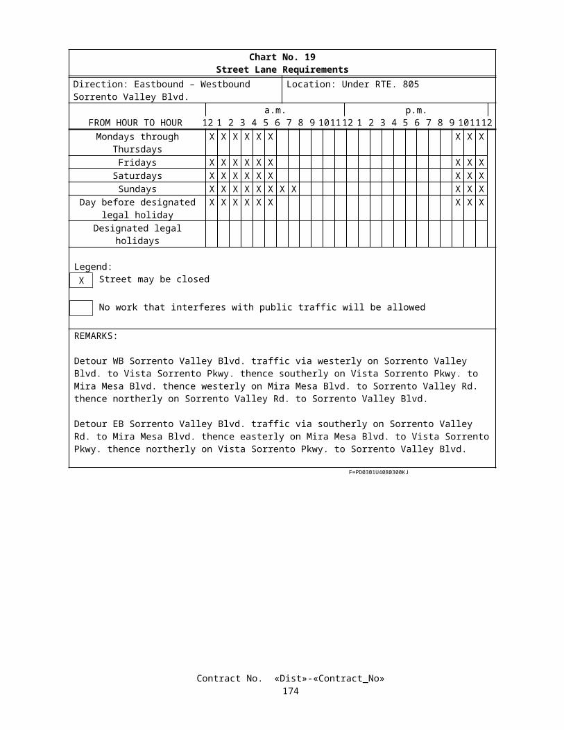
PAYMENTThe contract price paid per cubic meter for soil-cement shall include full compensation for furnishing all labor, materials,
tools, equipment, and incidentals, and for doing all the work involved in mixing soil-cement, complete-in-place, as shown on the plans, as specified in the Standard Specifications and these special provisions, and as directed by the Engineer.
Full compensation for soil-cement quality control shall be considered as included in the contract price paid per cubic meter for soil-cement and no separate payment will be allowed therefor.
Full compensation for containment and disposal of spoils shall be considered as included in the contract price paid per cubic meter for soil-cement and no separate payment will be allowed therefor.
10-1.42 PREFABRICATED VERTICAL DRAINThis work shall consist of furnishing and installing band-shaped type prefabricated vertical drains as shown on the plans
and specified in these special provisions.Prefabricated vertical drains shall extend to the top of the competent soils or rocks, or otherwise approved by the
Engineer.Attention is directed to “Order of Work” and “Obstructions” elsewhere in these special provisions. Attention is directed
to Section 7-1.11, “Preservation of Property,” of the Standard Specifications regarding damage from prefabricated vertical drain operations to existing utilities, improvements and facilities.
The Contractor shall review the foundation information provided in the plans. Additional foundation information is available for viewing at the Transportation Laboratory.
Difficult prefabricated vertical drain installation is anticipated due to the presence of groundwater, sporadic cobbles and gravels, interfingering layers of alluvial materials, subsurface concrete debris, underground utilities, overhead utilities, sound control, vibration monitoring, and traffic control.
MATERIALPrefabricated vertical drain shall be a prefabricated plastic drainage core wrapped in a filter of non-woven geotextile
material. The core shall be fabricated with suitable drainage channels/studs. The geotextile wrap shall be tight around the core, and shall be securely seamed in a manner that will not introduce any new materials nor present an obstruction that will impede the channels of the core. The prefabricated wick drain material shall be one of the following products or approved equivalents:
1. Alidrain2. Aldirain S3. Flexi-Drain4. Amerdrain (Type 407)5. Amerdrain (Type 417)6. Mebra-Drain (7407)7. Mdbra-Drain (MD 88)8. Colbonddrain CX 1000
The Contractor shall submit wick drain samples and indicate the source of the proposed materials prior to delivery to the site and shall allow 15 working days for the Engineer to evaluate the material. Approval of the sample material by the Engineer shall be required prior to site delivery of the prefabricated vertical drain material.
The prefabricated vertical drains shall be free of defects, rips, holes, or flaws. During shipment, the drain shall be protected from damage, and during storage on-site, the storage area shall be such that the drain is protected from sunlight, mud, dirt, dust, debris, and detrimental substances. Manufacturer certification shall be provided for all drain material delivered.
SUBMITTALSThe submittals and other additional submittals shall conform to the requirements in Section 5-1.02, “Plans and Working
Drawings,” of the Standard Specifications and these special provisions.Submittals shall be stamped by a California Registered Professional Civil Engineer except for survey data which shall be
stamped by a California Registered Professional Civil Engineer or a California Registered Land Surveyor.At least four weeks prior to commencement of any mobilization of prefabricated vertical drain installation, the
Contractor shall submit the following to the Engineer for approval:
1. Sample of prefabricated vertical drain material, material specification sheet, and name of manufacturer.
Contract No. «Dist»-«Contract_No»177

2. Size, type, weight, maximum pushing force, vibratory hammer rated energy and configurations of the installation rig.
3. Dimension and length of mandrel.
4. Details of wick drain anchorage.
5. Description of proposed installation procedures. and
6. Proposed method for splicing prefabricated vertical drains.
Within one working day after the end of a work shift, the Contractor shall submit Daily Production Reports for the work shift to the Engineer. Daily Production Reports shall be filled out, checked for correctness, and signed by the prefabricated vertical drain Contractor’s field superintendent and the Contractor's field superintendent at the end of every work shift. The reports shall contain, but not be limited, to the following information:
1. Day, month, year, time of work, shift, beginning and end; names of each superintendent in-charge of the Work for both the prefabricated vertical drain installation and the Contractor; a list of all workers' names associated with each prefabricated vertical drain rig; and a summary of equipment used during the shift.
2. In the event of any Contractor claim, the Daily Production Reports shall be the primary documents to substantiate the reasons and basis for the claim.
3. Summary of any downtime or unproductive time, including start and end time, duration, and reason.
Within five weeks after completion of prefabricated vertical drain installation, the Contractor shall submit survey data including:
1. A final Layout Plan of suitable scales showing the locations of each prefabricated vertical drain.
2. A tabular summary of layout center coordinates modified to reflect any measured- deviations of each prefabricated vertical drain at the top of the drain, the elevation of the top and bottom of each element.
VIBRATION, GROUND MOVEMENT, AND NOISE MONITORINGThe Contractor shall take precautions such that vibration and noise from the prefabricated vertical drain installation will
not cause undue interference or damage to neighboring properties or buildings.If, in the opinion of the Engineer, ground vibrations, movements or noise from prefabricated vertical drain installation
work adversely affect the project and neighboring properties and buildings, the Engineer may direct the Contractor to use alternative methods or procedures of prefabricated vertical drain installation. Alternate methods shall be subject to the prior approval of the Engineer but shall remain the responsibility of the Contractor.
CONSTRUCTIONField Superintendents shall be required on site, each shift of operation. The Field Superintendents shall each have at
least one-year experience and 5successful projects with prefabricated vertical drain installation similar to that required for the Work specified herein.
Prefabricated vertical drain rig operators shall have accumulated a minimum of 6 months accumulated experience with prefabricated vertical drain installation and a minimum of 100 hours of operating time on the specific prefabricated vertical drain installation rig under the direct supervision of the Field Superintendent and equipment manufacturer representative.
The Contractor's personnel responsible for survey layout, lines and grades, shall be Registered Land Surveyor or a Registered Professional Civil Engineer.
The Contractor shall locate, number, and stake out the prefabricated vertical drain locations. The location of prefabricated vertical drains shall vary no more than 150 mm from the locations on the plans or as directed by the Engineer.
Prefabricated vertical drain installation equipment shall cause a minimum disturbance of the subsoil during installation.The wick drains shall be installed using a mandrel or sleeve that will be advanced through subsoil to the required depth
using either static and/or vibratory methods. The mandrel shall protect the wick drain material from tears, cuts, and abrasions during installation and shall be withdrawn after the installation of the drain.
Contract No. «Dist»-«Contract_No»178

The mandrel shall be provided with a anchor plate or rod at the bottom to prevent soil from entering the bottom of the mandrel during installation of the drains and to anchor the bottom of the drain at the required depth and at the time of removing the mandrel. The mandrel shall have a maximum cross sectional area of 8000 mm2.
The equipment shall be carefully checked for plumbness prior to advancing each prefabricated vertical drain, and shall not deviate more than 50 mm per meter from the vertical.
Prefabricated vertical drains that are out of tolerance or that are damaged in construction, or that are improperly installed shall be rejected by the Engineer, and no compensation will be allowed for any materials furnished or for any work performed on such prefabricated vertical drains.
Prefabricated vertical drains shall be installed from the working surface to the elevation shown on the plans or as directed by the Engineer.
After the installation of each prefabricated vertical drain, the prefabricated vertical drain shall be cut so that a minimum of 150 mm of drain material extends above the top of the working surface.
Augering or other methods are permitted to loosen stiff or dense upper soils prior to the installation of the prefabricated vertical drains, provided that such augering or other methods do not extend more than 600 mm into the underlying compressible soils. A minimum length of 600 mm of prefabricated vertical drain material shall extend above the working surface to provide continuous drainage into the drainage blanket.
If obstructions are encountered that cannot be penetrated by the drain installation equipment, the Contractor shall notify the Engineer and under the Engineer’s inspection shall attempt to install an alternative drain within a 600 mm radius of the original design location. A maximum of 2 attempts shall be made as directed by the Engineer.
The Contractor shall provide means of determining the depth of the prefabricated vertical drain during installation.Splices or connections in the prefabricated vertical drain material shall ensure continuity of the prefabricated vertical
drain material. A minimum overlap of 150 mm shall be required for each splice.
MEASUREMENT AND PAYMENTPrefabricated vertical drains will be measured by the meter for the full length of drainage complete and in place. The contract price paid per meter for prefabricated vertical drain shall include full compensation for furnishing all labor,
materials, tools, equipment, and incidentals, and for doing all the work involved in installing prefabricated vertical drain, complete in place, as shown on the plans, as specified in the Standard Specifications and these special provisions, and as directed by the Engineer.
Prefabricated vertical drains installed as alternative drain to avoid obstructions will be paid for as extra work as provided in Section 4-1.03D of the Standard Specifications.
10-1.43 MOVE-IN/MOVE-OUT (EROSION CONTROL) Move-in/move-out (erosion control) shall include moving onto the project when an area is ready to receive erosion
control as determined by the Engineer, setting up all required personnel and equipment for the application of erosion control materials and moving out all personnel and equipment when erosion control in that area is completed.
When areas are ready to receive applications of temporary erosion control, temporary erosion control (Type 2) and temporary erosion control (Type 3) as determined by the Engineer, the Contractor shall begin erosion control work in that area within 5 working days of the Engineer’s notification to perform the erosion control work.
Attention is directed to the requirements of temporary erosion control, temporary erosion control (Type 2) and temporary erosion control (Type 3) elsewhere in these special provisions.
Quantities of move-in/move-out (erosion control) will be determined as units from actual count as determined by the Engineer. For measurement purposes, a move-in followed by a move-out will be considered as one unit.
The contract unit price paid for move-in/move-out (erosion control) shall include full compensation for furnishing all labor, materials (excluding erosion control materials), tools, equipment, and incidentals and for doing all the work involved in moving in and removing from the project all personnel and equipment necessary for application of temporary erosion control, temporary erosion control (Type 2) and temporary erosion control (Type 3) as shown on the plans, as specified in the Standard Specifications and these special provisions, and as directed by the Engineer.
No adjustment of compensation will be made for any increase or decrease in the quantities of move-in/move-out (erosion control) required, regardless of the reason for the increase or decrease. The provisions in Section 4-1.03B, "Increased or Decreased Quantities," of the Standard Specifications shall not apply to the item of move-in/move-out (erosion control).
10-1.44 TEMPORARY EROSION CONTROL (TYPE 2 AND TYPE 3)Erosion control (Type 2 and Type 3) shall conform to the provisions in Section 20-3, "Erosion Control," of the Standard
Specifications and these special provisions and shall consist of applying erosion control materials to embankment and excavation slopes and other areas disturbed by construction activities.
Erosion control (Type 2 and Type 3) shall be applied when an area is ready to receive erosion control as determined by the Engineer and in conformance with the provisions in "Move-in/Move-out (Erosion Control)" of these special provisions.
Contract No. «Dist»-«Contract_No»179

Prior to installing erosion control materials, soil surface preparation shall conform to the provisions in Section 19-2.05, "Slopes," of the Standard Specifications, except that rills and gullies exceeding 50 mm in depth or width shall be leveled. Vegetative growth, temporary erosion control materials, and other debris shall be removed from areas to receive erosion control.
MATERIALSMaterials shall conform to the provisions in Section 20-2, "Materials," of the Standard Specifications and these special
provisions.
SeedSeed shall conform to the provisions in Section 20-2.10, "Seed," of the Standard Specifications. Individual seed species
shall be measured and mixed in the presence of the Engineer.Seed shall be delivered to the project site in unopened separate containers with the seed tag attached. Containers without
a seed tag attached will not be accepted.A sample of approximately 30 g of seed will be taken from each seed container by the Engineer.
Legume SeedLegume seed shall be pellet-inoculated or industrial-inoculated and shall conform to the following:
A. Inoculated seed shall be inoculated in conformance with the provisions in Section 20-2.10, "Seed," of the Standard Specifications.
B. Inoculated seed shall have a calcium carbonate coating.C. Industrial-inoculated seed shall be inoculated with Rhizobia and coated using an industrial process by a
manufacturer whose principal business is seed coating and seed inoculation.D. Industrial-inoculated seed shall be sown within 180 calendar days after inoculation.E. Legume seed shall consist of the following:
LEGUME SEED(Type 2)
Botanical Name(Common Name)
Percent Germination (Minimum)
Kilograms Pure Live Seed Per Hectare(Slope Measurement)
Lotus scoparius(Deerweed)
35 1.5
Lupinus succulentus(Arroyo Lupine)
50 10
LEGUME SEED(Type 3)
Botanical Name(Common Name)
Percent Germination (Minimum)
Kilograms Pure Live Seed Per Hectare(Slope Measurement)
Lotus scoparius(Deerweed)
35 1.5
Lupinus succulentus(Arroyo Lupine)
50 10
Contract No. «Dist»-«Contract_No»180

Non-Legume SeedNon-legume seed shall consist of the following:
NON-LEGUME SEED(Type 2)
Botanical Name(Common Name)
Percent Germination(Minimum)
Kilograms Pure Live Seed Per Hectare(Slope Measurement)
Artemisia californica(California Sage Brush)
45 .25
Encelia californica(California Encelia)
35 2
Gnaphalium californicum(Green Everlasting)
20 .1
Stipa pulchra(Purple Needlegrass)(deawned)
35 3
Eriophyllum confertiflorum(Golden Yarrow)
35 .5
Salvia apiana(White Sage)
20 1
Salvia mellifera(Black Sage)
30 2
NON-LEGUME SEED(Type 3)
Botanical Name(Common Name)
Percent Germination(Minimum)
Kilograms Pure Live Seed Per Hectare(Slope Measurement)
Artemisia californica(California Sage Brush)
45 .25
Encelia californica(California Encelia)
35 2
Eriophyllum confertiflorum(Golden Yarrow)
35 .5
Eschscholzia californica(California Poppy)
60 3
Stipa pulchra(Purple Needlegrass)(deawned)
35 3
Salvia mellifera(Black Sage)
30 1
Vulpia microstachys(Small Fescue)
35 5
Commercial FertilizerCommercial fertilizer shall conform to the provisions in Section 20-2.02, "Commercial Fertilizer," of the Standard
Specifications and shall have a guaranteed chemical analysis of 6 percent nitrogen, 20 percent phosphoric acid and 20 percent water soluble potash.
CompostCompost shall be derived from green material consisting of chipped, shredded or ground vegetation or clean processed
recycled wood products or a Class A, exceptional quality biosolids composts, as required by the United States Environmental Protection Agency (EPA), 40 CFR, Part 503c regulations or a combination of green material and biosolids compost. The compost shall be processed or completed to reduce weed seeds, pathogens and deleterious material, and shall not contain paint, petroleum products, herbicides, fungicides or other chemical residues that would be harmful to plant or animal life. Other deleterious material, plastic, glass, metal or rocks shall not exceed 0.1 percent by weight or volume. A minimum internal temperature of 57˚C shall be maintained for at least 15 continuous days during the composting process. The compost shall be thoroughly turned a minimum of 5 times during the composting process and shall go through a minimum 90-day curing period after the 15-day thermophilic compost process has been completed. Compost shall be screened through a
Contract No. «Dist»-«Contract_No»181

maximum 9.5-mm screen. The moisture content of the compost shall not exceed 35 percent. Compost products with a higher moisture content may be used provided the weight of the compost is increased to equal the compost with a moisture content of 35 percent. Moist samples of compost on an as received basis shall be dried in an oven at a temperature between 105°C and 115°C until a constant dry weight of the sample is achieved. The percentage of moisture will be determined by dividing the dry weight of the sample by the moist weight of the sample and then multiplying by 100. Compost will be tested for maturity and stability with a Solvita test kit. The compost shall measure a minimum of 6 on the maturity and stability scale.
Stabilizing EmulsionStabilizing emulsion shall conform to the provisions in Section 20-2.11, "Stabilizing Emulsion," of the Standard
Specifications and these special provisions.Stabilizing emulsion shall be in a dry powder form, may be reemulsifiable, and shall be a processed organic adhesive
used as a soil tackifier.
APPLICATIONErosion control materials shall be applied in separate applications in the following sequence:
A. The following mixture in the proportions indicated shall be applied with hydro-seeding equipment within 60 minutes after the seed has been added to the mixture:
(Type 2)Material Kilograms Per Hectare
(Slope Measurement)Legume Seed 11.5Non-Legume Seed 8.85Fiber 1000Compost 800
(Type 3)Material Kilograms Per Hectare
(Slope Measurement)Legume Seed 11.5Non-Legume Seed 14.75Fiber 800Compost 1000
B. The following mixture in the proportions indicated shall be applied with hydro-seeding equipment:
(Type 2)Material Kilograms Per Hectare
(Slope Measurement)Fiber 700Compost 1000Commercial Fertilizer 25Stabilizing Emulsion (Solids) 150
(Type 3)Material Kilograms Per Hectare
(Slope Measurement)Fiber 1000Compost 800Commercial Fertilizer 25Stabilizing Emulsion (Solids) 300
The ratio of total water to total stabilizing emulsion in the mixture shall be as recommended by the manufacturer.The proportions of erosion control materials may be changed by the Engineer to meet field conditions.
Contract No. «Dist»-«Contract_No»182

MEASUREMENT AND PAYMENTFull compensation for compost shall be considered as included in the contract price paid per square meter for the various
types of temporary erosion control and no separate payment will be made therefor.The cost of maintaining the various types of temporary erosion control will be borne equally by the State and the
Contractor, as mentioned in "Water Pollution Control (Storm Water Pollution Prevention Plan)," elsewhere in these special provisions.
10-1.45 IRRIGATION CROSSOVERSIrrigation crossovers shall conform to the provisions in Section 20-5, "Irrigation Systems," of the Standard Specifications
and these special provisions.Conduits shall be placed in open trenches in conformance with the provisions in Section 20 -5.03B, "Conduit for
Irrigation Crossovers," of the Standard Specifications.Conduits shall be corrugated high density polyethylene (CHDPE) pipe. Corrugated high density polyethylene pipe shall
conform to the requirements in ASTM Designation: F 405 or F 667, or AASHTO Designation: M 252 or M 294 and shall be Type S. Couplings and fittings shall be as recommended by the pipe manufacturer.
Water line crossovers shall conform to the provisions in Section 20-5.03C, "Water Line Crossovers," of the Standard Specifications.
Sprinkler control crossovers shall conform to the provisions in Section 20-5.027D, "Sprinkler Control Crossovers," of the Standard Specifications.
Installation of pull boxes shall conform to the provisions in Section 20-5.027I, "Conductors, Electrical Conduit and Pull Boxes," of the Standard Specifications. When no conductors are installed in electrical conduits, pull boxes for irrigation crossovers shall be installed on a foundation of compacted soil.
10-1.46 EXTEND IRRIGATION CROSSOVERSExtend existing irrigation crossovers shall conform to the provisions in Section 20-5, "Irrigation Systems," of the
Standard Specifications and these special provisions.Extend irrigation crossovers shall include conduit, water line crossover, and sprinkler control crossover extensions and
appurtenances, locating existing irrigation crossovers and pressure testing existing and new water line crossovers. The sizes of conduit, water line crossover, and sprinkler control crossover extensions shall be as shown on the plans.
Before work is started in an area where an existing irrigation crossover conduit is to be extended, the existing conduit shall be located by the Contractor. When exploratory holes are used to locate the existing conduit, the exploratory holes shall be excavated in conformance with the provisions in Section 20-5.03B, "Conduit for Irrigation Crossovers," of the Standard Specifications.
If debris is encountered in the ends of conduits to be extended, the debris shall be removed prior to extending conduits. Removal of debris within the first meter in the conduits shall be at the Contractor's expense. If debris is encountered in the conduit more than one meter from the ends of the conduits to be extended, the additional debris shall be removed as directed by the Engineer and will be paid for as extra work as provided in Section 4-1.03D of the Standard Specifications.
Prior to installation of water line crossover extensions, the existing water lines shall be pressure tested for leakage in conformance with the provisions in Section 20-5.03H, "Pressure Testing," of the Standard Specifications. Repairs to the existing water line crossover, when ordered by the Engineer, will be paid for as extra work as provided in Section 4 -1.03D of the Standard Specifications.
Conduit extensions shall be corrugated high density polyethylene (CHDPE) pipe.Water line crossover extensions shall be plastic pipe (PR 315) (supply line).Sprinkler control crossover extensions shall be Type 3 electrical conduit.Conductors shall be removed from existing sprinkler control crossovers to be extended.After installation of the sprinkler control crossover extensions, new conductors shall be installed without splices in
existing and extended sprinkler control crossovers. New conductors shall match the removed conductors in color and size and shall be spliced to the existing conductors in adjacent pull boxes. After the new conductors are installed, the conductors shall be tested in the same manner specified for traffic signal, sign illumination, and lighting circuits in conformance with the provisions in Section 86-2.14B, "Field Testing," of the Standard Specifications.
After water line crossover extensions have been installed, existing and extended water line crossovers shall be retested for leakage in conformance with the provisions in Section 20-5.03H, "Pressure Testing," of the Standard Specifications. Leaks that develop shall be repaired at the Contractor's expense and the water line crossovers shall be retested until a satisfactory pressure test is achieved.
Contract No. «Dist»-«Contract_No»183

10-1.47 IMPORTED TOPSOILImported topsoil shall conform to the provisions in Section 20-2, "Materials," and Section 20-3, "Erosion Control," of the
Standard Specifications.
10-1.48 TRANSPLANT EXISTING TREESTransplanting existing trees shall conform to the provisions in Section 20-4, "Highway Planting," of the Standard
Specifications and these special provisions.Existing trees to be transplanted shall be removed and either stored or transplanted to their new locations shown on the
plans prior to performing other work within the location of the existing trees.When the trees are removed and the work within the areas to which the trees are to be transplanted is not completed to
the stage at which the trees can be planted, the trees shall be stored and maintained until transplanting can be completed. In other cases, the trees shall be planted at the new locations the same day the trees are removed.
Trees to be transplanted shall be pruned just prior to removing the trees. Pruning of trees to be transplanted shall include removal of broken or bruised branches 25 mm or larger in diameter, deadwood, and suckers. Pruning shall be in conformance with the provisions in Section 20-4.055, "Pruning," of the Standard Specifications. Tree seal compounds shall not be used to cover pruning cuts.
Removed pruned materials shall be disposed of outside the highway right of way in conformance with the provisions in Section 7-l.13, "Disposal of Material Outside the Highway Right of Way," of the Standard Specifications.
The Contractor shall determine the methods to be used to transplant trees, including removing, transporting, storing if required, planting, guying, and maintaining the trees. The Contractor shall submit a proposed plan for this work, in writing, to the Engineer prior to the start of the work. The proposed plan shall include, but not necessarily be limited to, root ball size, method of root ball containment, and maintenance programs for each tree to be transplanted.
When trees are planted, a root stimulant, approved by the Engineer, shall be applied to the roots of each tree in conformance with the printed instructions of the root stimulant manufacturer. A copy of the instructions shall be furnished to the Engineer before applying any stimulant. Root stimulant to be used shall be submitted to the Engineer not less than 2 weeks prior to the stimulant's intended use. Root stimulants not approved by the Engineer shall not be used.
Holes resulting from the removal of transplanted trees shall be backfilled the same day the trees are removed. Soil from the surrounding area may be used to backfill these holes. The backfill shall be graded to conform with the adjacent existing grade.
Watering basins shall be constructed around each transplanted tree.Trees to be transplanted shall be maintained from the time the trees are removed to the time of acceptance of the
contract. The trees shall be watered and fertilized as necessary to maintain the trees in a healthy condition. Trash, debris and weeds within basins, including the basin walls, shall be removed and disposed of outside the highway right of way in conformance with the provisions in Section 7-1.13, "Disposal of Material Outside the Highway Right of Way," of the Standard Specifications. Weeds shall be removed before the weeds exceed 50 mm in length. Pesticides to be used for weed control shall be submitted to the Engineer not less than 2 weeks prior to the intended use. Pesticides not approved by the Engineer shall not be used.
The provisions in Section 20-4.07, "Replacement," of the Standard Specifications for the replacement of unsuitable plants shall apply to transplanted trees. The replacement tree for each unsuitable transplanted tree shall be the same species as the tree being replaced, except 4-900 mm box trees shall be planted instead of one tree of the size originally transplanted. The 600 mm box trees shall be planted in individual plant holes at the locations designated by the Engineer within the area of the tree being replaced. Removed unsuitable transplanted trees shall be disposed of outside the highway right of way in conformance with the provisions in Section 7-1.13, "Disposal of Material Outside the Highway Right of Way," of the Standard Specifications.
The quantity of transplant trees will be measured by the unit as determined from actual count in place, excluding additional replacement trees.
The contract unit price paid for transplant tree shall include full compensation for furnishing all labor, materials, tools, equipment, and incidentals, and for doing all the work involved in transplanting trees, complete in place, as shown on the plans, as specified in the Standard Specifications and these special provisions, and as directed by the Engineer.
10-1.49 FINISHING ROADWAYFinishing roadway shall conform to the provisions in Section 22, "Finishing Roadway," of the Standard Specifications.
10-1.50 AGGREGATE SUBBASEAggregate subbase shall be Class 4 and shall conform to the provisions in Section 25, "Aggregate Subbases," of the
Standard Specifications and these special provisions.
Contract No. «Dist»-«Contract_No»184

The restriction that the amount of reclaimed material included in Class 4 aggregate subbase not exceed 50 percent of the total volume of the aggregate used shall not apply. Aggregate for Class 4 aggregate subbase may include reclaimed glass. Aggregate subbase incorporating reclaimed glass shall not be placed at locations where surfacing will not be placed over the aggregate subbase.
The percentage composition by mass of Class 4 aggregate subbase shall conform to the following grading requirements:
Grading Requirements (Percentage Passing)Sieve Sizes Operating Range Contract Compliance
150-mm 100 100100-mm 90-100 87-1004.75-mm 35-100 30-100600-µm 0-60 0-6575-µm 0-20 0-23
Class 4 aggregate subbase shall also conform to the following quality requirements:
Quality RequirementsTest Operating Range Contract Compliance
Sand Equivalent 25 Min. 22 Min.Resistance (R-value) ---- 60 Min.
The provisions of the last 4 paragraphs in Section 25-1.02A, "Class 1, Class 2, and Class 3 Aggregate Subbases," of the Standard Specifications shall apply to Class 4 aggregate subbase.
At the option of the Contractor, Class 1 aggregate subbase conforming to the grading and quality requirements in Section 25-1.02A, may be used in place of Class 4 aggregate subbase. The restriction that the amount of reclaimed material included in Class 1 aggregate subbase not exceed 50 percent of the total volume of the aggregate used shall not apply. Aggregate for Class 1 aggregate subbase may include reclaimed glass. Aggregate subbase incorporating reclaimed glass shall not be placed at locations where surfacing will not be placed over the aggregate subbase. Once a class of aggregate subbase is selected, the class shall not be changed without written approval of the Engineer.
Regardless of the class of aggregate subbase supplied under the provisions of this section, payment for all aggregate subbase will be made as Class 4 aggregate subbase.
10-1.51 AGGREGATE BASEAggregate base shall be Class 2 and shall conform to the provisions in Section 26, "Aggregate Bases," of the Standard
Specifications and these special provisions.The restriction that the amount of reclaimed material included in Class 2 aggregate base not exceed 50 percent of the
total volume of the aggregate used shall not apply. Aggregate for Class 2 aggregate base may include reclaimed glass. Aggregate base incorporating reclaimed glass shall not be placed at locations where surfacing will not be placed over the aggregate base.
10-1.52 ASPHALT CONCRETEAsphalt concrete and asphalt concrete base shall be Type A and shall conform to the provisions in Section 39, "Asphalt
Concrete," of the Standard Specifications and these special provisions.The amount of asphalt binder used in asphalt concrete placed in dikes, gutters, gutter flares, overside drains and aprons at
the ends of drainage structures shall be increased one percent by mass of the aggregate over the amount of asphalt binder determined for use in asphalt concrete placed on the traveled way.
Asphalt concrete and asphalt concrete base placed in layers of 45 mm or less in compacted thickness or widths of less than 1.5 m shall be spread and compacted with the equipment and by the methods conforming to the provisions in Section 39, "Asphalt Concrete," of the Standard Specifications. Other asphalt concrete and asphalt concrete base shall be compacted and finished in conformance with the provisions in Section 39 and the following:
A. The provisions in Section 39-5.02, "Compacting Equipment," of the Standard Specifications shall not apply.B. The Contractor shall furnish a sufficient number of rollers to obtain the compaction specified in these special
provisions and the surface finish required by the Standard Specifications and these special provisions.C. Rollers shall be equipped with pads and water systems that prevent sticking of asphalt mixtures to the
pneumatic-tired or steel-tired wheels. A parting agent that will not damage the asphalt mixture may be used.D. The second paragraph in Section 39-6.01, "General Requirements," of the Standard Specifications shall not apply.
Contract No. «Dist»-«Contract_No»185
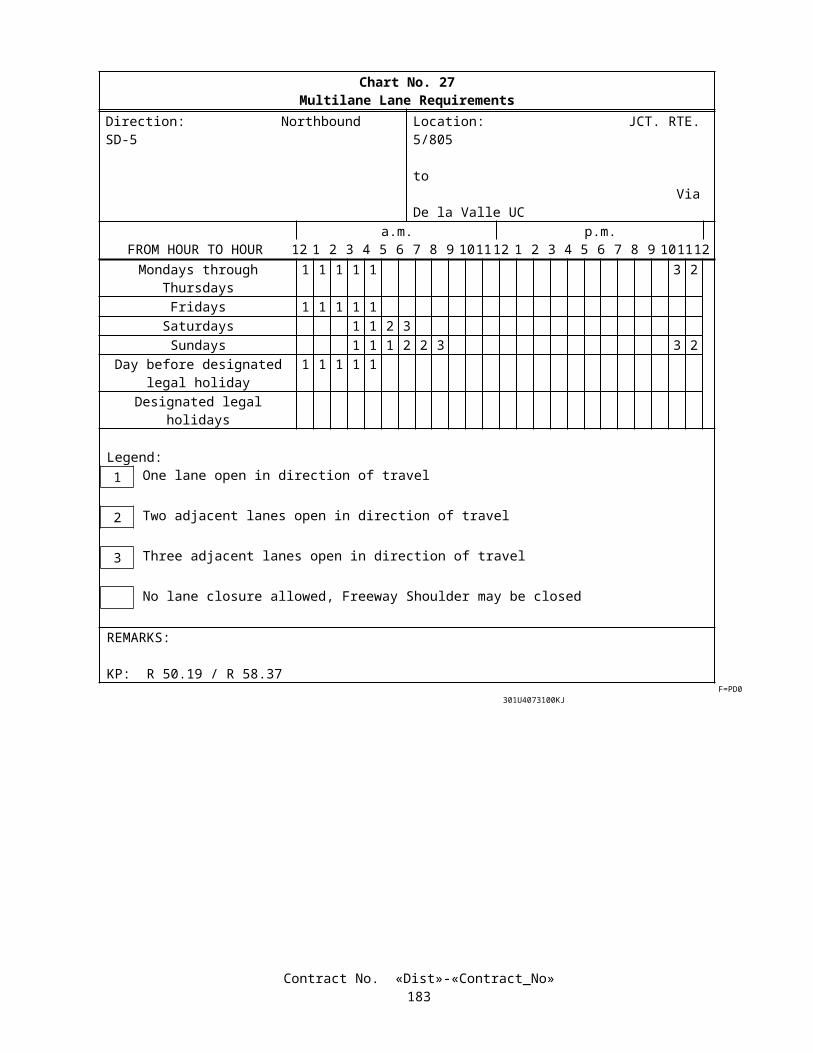
E. Asphalt concrete and asphalt concrete base shall be compacted by any means to obtain the specified relative compaction before the temperature of the mixture drops below 65°C. Additional rolling to achieve the specified relative compaction will not be permitted after the temperature of the mixture drops below 65°C or once the pavement is opened to public traffic. When vibratory rollers are used as finish rollers the vibratory unit shall be turned off.
F. The fifth and seventh through tenth paragraphs of Section 39-6.03, "Compacting," of the Standard Specifications shall not apply.
G. Asphalt concrete and asphalt concrete base shall be compacted to a relative compaction of not less than 96.0 percent and shall be finished to the lines, grades, and cross section shown on the plans. In-place density of asphalt concrete and asphalt concrete base will be determined prior to opening the pavement to public traffic.
H. Relative compaction will be determined by California Test 375.I. If the test results for a quantity of asphalt concrete or asphalt concrete base indicate that the relative compaction is
below 96.0 percent, the Contractor will be notified. Asphalt concrete or asphalt concrete base spreading operations shall not continue until the Contractor has notified the Engineer of the adjustment that will be made in order to meet the specified relative compaction.
J. If the test results for a quantity of asphalt concrete or asphalt concrete base indicate that the relative compaction is less than 96.0 percent, the asphalt concrete or asphalt concrete base represented by that quantity shall be removed, except as otherwise provided in these special provisions. If requested by the Contractor and approved by the Engineer, asphalt concrete or asphalt concrete base with a relative compaction of 93.0 percent or greater may remain in place and the Contractor shall pay to the State the amount of reduced compensation for the quantity with relative compaction less than 96.0 percent and greater than or equal to 93.0 percent. The Department will deduct the amount of reduced compensation from moneys due, or that may become due, the Contractor under the contract. The amount of reduced compensation the Contractor shall pay to the State will be calculated using the total tonnes in the quantity with relative compaction less than 96.0 percent and greater than or equal to 93.0 percent multiplied by the contract price per tonne for asphalt concrete or asphalt concrete base involved multiplied by the following compensation factors:
Relative Compaction (Percent)
Reduced Compensation Factor
Relative Compaction (Percent)
Reduced Compensation Factor
96.0 0.000 94.4 0.06295.9 0.002 94.3 0.06895.8 0.004 94.2 0.07595.7 0.006 94.1 0.08295.6 0.009 94.0 0.09095.5 0.012 93.9 0.09895.4 0.015 93.8 0.10895.3 0.018 93.7 0.11895.2 0.022 93.6 0.12995.1 0.026 93.5 0.14295.0 0.030 93.4 0.15794.9 0.034 93.3 0.17594.8 0.039 93.2 0.19694.7 0.044 93.1 0.22594.6 0.050 93.0 0.30094.5 0.056
Planned roads and connections used as detours shall be paved, except that the top layer of asphalt concrete shall be deferred until temporary striping is no longer needed.
The miscellaneous areas to be paid for at the contract price per square meter for place asphalt concrete (miscellaneous area), in addition to the prices paid for the materials involved, shall be limited to the areas listed on the plans.
Aggregate for asphalt concrete dikes and miscellaneous areas shall be in conformance with the provisions for 9.5-mm Maximum grading in Section 39-2.02, "Aggregate," of the Standard Specifications.
If the Contractor selects the batch mixing method, asphalt concrete shall be produced by the automatic batch mixing method in conformance with the provisions in Section 39-3.03A(2), "Automatic Proportioning," of the Standard Specifications.
Contract No. «Dist»-«Contract_No»186

In addition to the provisions in Section 39-5.01, "Spreading Equipment," of the Standard Specifications, asphalt paving equipment shall be equipped with automatic screed controls and a sensing device or devices.
When placing asphalt concrete to the lines and grades established by the Engineer, the automatic controls shall control the longitudinal grade and transverse slope of the screed. Grade and slope references shall be furnished, installed, and maintained by the Contractor. Should the Contractor elect to use a ski device, the minimum length of the ski device shall be 9 m. The ski device shall be a rigid one piece unit and the entire length shall be utilized in activating the sensor.
When placing the initial mat of asphalt concrete on existing pavement, the end of the screed nearest the centerline shall be controlled by a sensor activated by a ski device not less than 9 m long. The end of the screed farthest from centerline shall be controlled by a sensor activated by a similar ski device or by an automatic transverse slope device set to reproduce the cross slope designated by the Engineer.
When paving contiguously with previously placed mats, the end of the screed adjacent to the previously placed mat shall be controlled by a sensor that responds to the grade of the previously placed mat and will reproduce the grade in the new mat within a 3-mm tolerance. The end of the screed farthest from the previously placed mat shall be controlled in the same way it was controlled when placing the initial mat.
Should the methods and equipment furnished by the Contractor fail to produce a layer of asphalt concrete conforming to the provisions, including straightedge tolerance, of Section 39-6.03, "Compacting," of the Standard Specifications, the paving operations shall be discontinued and the Contractor shall modify the equipment or methods, or furnish substitute equipment.
Should the automatic screed controls fail to operate properly during a day's work, the Contractor may manually control the spreading equipment for the remainder of that day. However, the equipment shall be corrected or replaced with alternative automatically controlled equipment conforming to the provisions in this section before starting another day's work.
In addition to the straightedge provisions in Section 39-6.03, "Compacting," of the Standard Specifications, asphalt concrete pavement shall conform to the surface tolerances specified herein.
The top surface of the uppermost layer of asphalt concrete surfacing shall be profiled by the Contractor, in the presence of the Engineer, using a California Profilograph or equivalent in conformance with California Test 526 and as specified in these special provisions. Prior to beginning profiles, the profilograph shall be calibrated in the presence of the Engineer. Profiles shall be made on the traveled way one meter from and parallel to each edge of the traveled way and at the approximate location of the planned lane lines.
Pavement so profiled shall conform to the following profile requirements:
A. Pavement shall not have individual deviations in excess of 8 mm, as determined by California Test 526. The station location of the profiles for determining deviations shall be designated by the Engineer.
Checking the following areas of pavement surface with the California Profilograph or equivalent will not be required:
A. Pavement on horizontal curves having a centerline curve radius of less than 300 m and pavement within the superelevation transition of such curves.
B. Pavement with a total thickness of 60 mm or less or pavement with extensive grade correction which does not receive advance leveling operations as in conformance to the provisions in Section 39-6.02, "Spreading," of the Standard Specifications.
C. Pavement for ramps and connectors with grades 8 percent or steeper and superelevation rates greater than 10 percent and short sections of city or county streets and roads, as determined by the Engineer.
D. Pavement within 15 m of a transverse joint that separates the pavement from an existing pavement not constructed under the contract.
E. Shoulders and miscellaneous areas.
The top surface of the uppermost layer of asphalt concrete surfacing that does not meet the specified surface tolerances shall be brought within tolerance by abrasive grinding. Areas which have been subject to abrasive grinding shall receive a fog seal coat. Deviations in excess of 8 mm which cannot be brought into specified surface tolerances by abrasive grinding shall be corrected by either (1) removal and replacement or (2) placing an overlay of asphalt concrete. The corrective method for each area shall be selected by the Contractor and shall be approved by the Engineer prior to beginning the corrective work. Replacement or overlay pavement not meeting the specified tolerances shall be corrected by the methods specified above. Corrective work shall be at the Contractor's expense except that flagging costs will be paid for in conformance to the provisions in Section 12-2, "Flagging," of the Standard Specifications.
After abrasive grinding has been completed to reduce individual deviations in excess of 8 mm, additional grinding or corrections to the surface as specified above shall be performed as necessary to reduce the profile of the pavement to the specified profile value required for the area. The Contractor shall run profilograms on the areas that have received abrasive grinding or corrective work until the final profilograms indicate the profile of the area is within the specified tolerance.
Contract No. «Dist»-«Contract_No»187

When abrasive grinding is used to bring the top surface of the uppermost layer of asphalt concrete surfacing within the specified surface tolerances, additional abrasive grinding shall be performed as necessary to extend the area ground in each lateral direction so that the lateral limits of grinding are at a constant offset from, and parallel to, the nearest lane line or pavement edge, and in each longitudinal direction so that the grinding begins and ends at lines normal to the pavement centerline, within a ground area. Ground areas shall be neat rectangular areas of uniform surface appearance.
Abrasive grinding shall conform to the provisions in the first paragraph and the last 4 paragraphs in Section 42-2.02, "Construction," of the Standard Specifications, except that the grinding residue shall be disposed of outside the highway right of way.
The original of the final profilograms that indicate the pavement surface is within the profile specified shall become the property of the State and shall be delivered to the Engineer prior to acceptance of the contract.
The Contractor shall provide, while performing profilograph and straightedge operations, a shadow vehicle. The shadow vehicle shall consist of a truck mounted crash cushion conforming to "Traffic Control System for Lane Closure" elsewhere in these special provisions. The shadow vehicle shall operate within a stationary lane closure. The shadow vehicle shall maintain a 23 to 25 meter distance from the profilograph or straightedge operation at all times.
Full compensation for performing all profile checks for profile and furnishing final profilograms to the Engineer, for performing all corrective work to the pavement surface including providing a shadow vehicle, abrasive grinding, removing, and replacing asphalt concrete or placing an asphalt concrete overlay to bring the surface within the tolerance specified shall be considered as included in the contract price paid per tonne for asphalt concrete (Type A) and no separate payment will be made therefor.
The area to which paint binder has been applied shall be closed to public traffic. Care shall be taken to avoid tracking binder material onto existing pavement surfaces beyond the limits of construction.
A drop-off of more than 45 mm will not be allowed at any time between adjacent lanes open to public traffic.Shoulders or median borders adjacent to a lane being paved shall be surfaced prior to opening the lane to public traffic.
The aggregate from each separate bin used for asphalt concrete base and asphalt concrete, Type A, except for the bin containing the fine material, shall have a Cleanness Value of 57 minimum for contract compliance and a value of 65 minimum for operating range as determined by California Test 227, modified as follows:
A. Tests will be performed on the material retained on the 2.36-mm sieve from each bin and will not be a combined or averaged result.
B. Each test specimen will be prepared by hand shaking for 30 seconds, a single loading of the entire sample on a 305-mm diameter, 4.75-mm sieve, nested on top of a 305-mm diameter, 2.36-mm sieve.
C. Where a coarse aggregate bin contains material which will pass the maximum size specified and is retained on a 9.5-mm sieve, the test specimen mass and volume of wash water specified for 25-mm x 4.75-mm aggregate size will be used.
D. Samples will be obtained from the weigh box area during or immediately after discharge from each bin of the batching plant or immediately prior to mixing with asphalt in the case of continuous mixers.
E. The Cleanness Value of the test sample from each of the bins will be separately computed and reported.
At drier-drum and continuous plants with cold feed control, Cleanness Value test samples will be obtained from the discharge of each coarse aggregate storage. An aggregate sampling device shall be provided which will provide a 25 -kg sample of each coarse aggregate.
If the results of the Cleanness Value tests do not meet the requirements specified for operating range but meet the contract compliance requirements, placement of the material may be continued for the remainder of that day. However, another day's work may not be started until tests, or other information, indicate to the satisfaction of the Engineer that the next material to be used in the work will comply with the requirements specified for operating range.
If the results of the Cleanness Value tests do not meet the requirements specified for contract compliance, the material which is represented by these tests shall be removed. However, if requested by the Contractor and approved by the Engineer, material having a Cleanness Value of 48 or greater may remain in place and accepted on the basis of a reduced payment for material left in place.
Asphalt concrete or asphalt concrete base that is accepted on the basis of reduced payment will be paid for at the contract prices for the items of asphalt concrete involved multiplied by the following factors:
Contract No. «Dist»-«Contract_No»188

Test Value Pay Factor56 0.9055 0.8554 0.8053 0.7552 0.7051 0.6550 0.6049 0.5548 0.50
If asphalt concrete or asphalt concrete base is accepted on the basis of reduced payment due to a Cleanness Value of 48 to 56 and also accepted on the basis of aggregate grading or Sand Equivalent tests not meeting the contract compliance requirements, the reduced payment for Cleanness Value shall apply and payment by the Contractor to the State for asphalt concrete not meeting the contract compliance requirements for aggregate grading or Sand Equivalent shall not apply.
10-1.53 CONCRETE PAVEMENT (WITH DOWELED TRANSVERSE WEAKENED PLANE JOINTS)
GENERALPortland cement concrete pavement shall conform to the provisions in Section 40, "Portland Cement Concrete
Pavement," of the Standard Specifications and these special provisions.Insert method for forming joints in pavement shall not be used.
PREPAVING CONFERENCESupervisory personnel of the Contractor and any subcontractor who are to be involved in the concrete paving work shall
meet with the Engineer at a prepaving conference, at a mutually agreed time, to discuss methods of accomplishing all phases of the paving work.
The Contractor shall provide the facility for the prepaving conference. Attendance at the prepaving conference is mandatory for the Contractor's project superintendent, paving construction foreman, paving subcontractors, concrete plant operations personnel (including plant supervisors, manager, and operator) and paving operators. All conference attendees will sign an attendance sheet provided by the Engineer. Production and placement shall not begin nor proceed unless the above-mentioned personnel have attended the mandatory prepaving conference.
The above-mentioned personnel along with the Engineer's representatives shall attend a 4-hour training class on portland cement concrete and paving techniques as part of the prepaving conference. This training class time will be in addition to the regular conference time. The class shall be scheduled no more than 2 weeks prior to the placement of portland cement concrete pavement. The class shall be held during normal working hours. Selection of the instructor of the class shall be as agreed to by the Engineer and the Contractor.
TEST STRIPAt the beginning of paving operations, the Contractor shall construct an initial test strip of concrete pavement at least
200 meters, but not more than 300 meters, in length at the specified paving width. If the test strip conforms to specifications, it will become part of the project's paving surface and will be measured and paid for as concrete pavement and seal pavement joint. The Engineer will determine the specified paving width. The Contractor shall use the same equipment for the remainder of the paving operations. The Contractor shall not perform further paving until the test strip is evaluated in conformance with the provisions in Section 40-1.10, "Final Finishing," of the Standard Specifications regarding surface straight edge and profile requirements; for dowel and tie bar alignment verification; concrete quality; and pavement thickness. An additional test strip will be required when:
1. The Contractor proposes using different paving equipment including the batch plant, paver, dowel inserter, tie bar inserter, tining, or curing equipment, or
2. Any portion of a test strip fails to conform to the provisions in Section 40-1.10, "Final Finishing," of the Standard Specifications for straight edge and profile requirements without the use of grinding or other corrective method, or
3. The dowel tolerances are not met, or4. The pavement thickness deficiency is greater than 15 mm, or5. A change in concrete mix design has occurred.
Contract No. «Dist»-«Contract_No»189
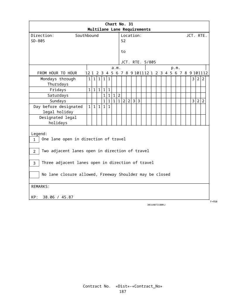
The Contractor shall perform coring of the test strips, as directed by the Engineer, as part of the dowel or tie bar placement tolerance verification. A minimum of six dowel bars shall be cored for each test strip. After removal of cores, voids in concrete pavement shall be cleaned and filled with hydraulic cement grout conforming to the provisions in "Core Drilling for Dowel Placement Alignment Assurance Testing" of these special provisions.
Regardless of the placement method [load transfer assemblies (dowel baskets) or mechanical inserters] chosen by the Contractor, after the initial test strip is placed, operations shall be suspended until the Engineer has sufficient time to inspect dowel positioning to insure that proper alignment of dowels is being achieved. Dowel alignment tolerance allowance shall be in conformance to the requirements of these special provisions.
If mechanical inserters are to be used, the Contractor shall demonstrate that the insertion equipment will not leave surface irregularities such as depressions, dips, or high areas adjacent to the dowel insertion point.
Prior to placement of the test strip, the Contractor shall submit a written procedure to locate transverse weakened plane joints that will coincide with the center of the dowels being placed. This procedure shall take into account inadvertent covering of paint markings after applying curing compound, misalignment by transferring marking spots, and inadequate staking of joints.
The Contractor shall change methods or equipment and construct additional test strips until a test strip conforms to the provisions in Section 40-1.10, "Final Finishing," of the Standard Specifications, and dowel bar alignment verification, without grinding or other corrective work. Each additional test strip shall be limited to 200 meters in length.
If test strip fails to conform to the specifications, before grinding, test strip shall be removed at the Contractor's expense. Additional test strips shall be constructed until the Contractor can demonstrate that test strip will conform to the requirements of these specifications.
The Engineer may waive the initial test strip if the Contractor proposes to use a batch plant mixer and paving equipment with the same personnel that were satisfactorily used on a Department project within the preceding 12 months and the mixer has not been altered or moved. The personnel shall be individuals listed in the prepaving conference used on the preceding Department project.
Materials resulting from the construction of all rejected test strips shall become the property of the Contractor and shall be removed and disposed of in conformance with the provisions in Section 7-1.13, "Disposal of Material Outside the Highway Right of Way," of the Standard Specifications.
MATERIALS
ConcreteThe concrete for pavement shall contain a minimum of 350 kilograms of portland cement per cubic meter.
Tie BarsTie bars shall be deformed reinforcing steel bars conforming to the requirements of ASTM Designation: A 615/A 615M,
Grade 300 or 420, and shall be epoxy-coated in conformance with the provisions in Section 52-1.02B, "Epoxy-coated Reinforcement," of the Standard Specifications, except that references made to ASTM Designation D 3963 shall be deemed to mean ASTM Designation A 934 or A 775. Epoxy-coated tie bars shall not be bent after installation.
EpoxyIf used, epoxy resin to bond tie bars to existing concrete shall conform to the provisions in Section 95 -2.03, "Epoxy
Resin Adhesive for Bonding New Concrete to Old Concrete," of the Standard Specifications.
DowelsDowels shall be smooth, round, epoxy-coated steel conforming to the requirements of ASTM Designation:
A 615/A 615M, Grade 300 or 420, the details shown on the plans and the provisions in Section 52-1.02B, "Epoxy-coated Reinforcement," of the Standard Specifications, except that references made to ASTM Designation D 3963/D 3963M shall be deemed to mean ASTM Designation A 934/A 934M.
Dowels shall be plain, smooth, round bars. Dowels shall be free from burrs or other deformations detrimental to free movement of the bars in the concrete.
Bond BreakerDowels shall be lubricated with a bond breaker over the entire bar. A bond breaker application of petroleum paraffin
based lubricant or white pigmented curing compound shall be used to coat the dowels completely prior to placement. Oil and asphalt based bond breakers shall not be used. Paraffin based lubricant shall be Dayton Superior DSC BB-Coat or Valvoline Tectyl 506 or an approved equal. Paraffin based lubricant shall be factory applied. White pigmented curing compound shall conform to the requirements of ASTM Designation: C309, Type 2, Class A, and shall contain 22 percent minimum
Contract No. «Dist»-«Contract_No»190

nonvolatile vehicles consisting of at least 50 percent paraffin wax. Curing compound shall be applied in two separate applications. Each application of curing compound shall be applied at the approximate rate of one liter per 3.7 m2.
Load Transfer Assemblies (Dowel Basket)Load transfer assemblies shall be manufactured with a minimum welded wire gage number of 3/0 (9.2 mm). Assemblies
shall be either a U- or a A-frame. J-frame shapes shall not be used. Assemblies shall be fabricated in conformance with the requirements of ASTM Designation: A 82. Welding of assemblies shall conform to the requirements of AWS D1.1. A broken weld will be a cause for rejection of the assembly. Assemblies shall be epoxy coated in conformance with the requirements of ASTM Designation: A 884/A 884M.
Wire for staking pins shall conform to the requirements of ASTM Designation: A 82. Staking pins shall not be less than 7 mm wire diameter.
Concrete fasteners shall be driven fasteners (concrete nails) used specifically for fastening to hardened concrete conforming to the requirements of ASTM Designation: F1667. Shank diameter shall be a minimum of 4 mm with a minimum shank length of 64 mm. Clips shall be commercial quality manufactured for use with dowel assemblies.
Surface of staking pins, concrete fasteners and clips shall be either zinc electroplated or galvanized with a minimum coating thickness of 0.005 mm.
Silicone Joint SealantLow modulus silicone joint sealant shall be furnished in a one-part silicone formulation. Acid cure sealants shall not be
used. The compound shall be compatible with the surface to which it is applied and shall conform to the following requirements:
Specification Test Method RequirementTensile stress, 150% elongation, 7-day cure at 25°± 1°C and 45% to 55% R.H.e
ASTM D 412 (Die C)
310 kPa max.
Flow at 25° ± 1°C ASTM C 639a Shall not flow from channelExtrusion Rate at 25° ± 1°C ASTM C 603b 75-250 g/min.Specific Gravity ASTM D 792
Method A1.01 to 1.51
Durometer Hardness, at -18°C, Shore A, cured 7 days at 25° ± 1°C
ASTM C 661 10 to 25
Ozone and Ultraviolet Resistance, after 5000 hours ASTM C 793 No chalking, cracking or bond loss
Tack free at 25° ± 1°C and 45% to 55% R.H.e ASTM C 679 Less than 75 minutesElongation, 7 day cure at 25° ± 1°C and 45% to 55% R.H.e ASTM D 412
(Die C)500 percent min.
Set to Touch, at 25° ± 1°C and 45% to 55% R.H.e ASTM D 1640 Less than 75 minutesShelf Life, from date of shipment — 6 months min.Bond, to concrete mortar-concrete briquets, air cured 7 days at 25° ± 1°C
AASHTO T 132c 345 kPa min.
Movement Capability and Adhesion, 100% extension at -18°C after, air cured 7 days at 25° ± 1°C, and followed by 7 days in water at 25° ± 1°C
ASTM C 719d No adhesive or cohesive failure after 5 cycles
Notes:a. ASTM Designation: C 639 Modified (15 percent slope channel A).b. ASTM Designation: C 603, through 3-mm opening at 345 kPa.c. Mold briquets in conformance with AASHTO Designation: T 132, sawed in half and bonded with a 1.5 mm maximum thickness of sealant and tested in conformance with AASHTO Designation: T 132. Briquets shall be dried to constant mass at 100 ± 5° C.d. Movement Capability and Adhesion: Prepare 305 mm x 25 mm x 75 mm concrete blocks in conformance with ASTM Designation: C 719. A sawed face shall be used for bond surface. Seal 50 mm of block leaving 12.5 mm on each end of specimen unsealed. The depth of sealant shall be 9.5 mm and the width 12.5 mm.e. R.H. equals relative humidity.
Contract No. «Dist»-«Contract_No»191

The silicone joint sealant shall be formulated to cure rapidly enough to prevent flow after application on grades of up to 15 percent.
A Certificate of Compliance for the silicone sealant shall be furnished to the Engineer in conformance with the provisions in Section 6-1.07, "Certificates of Compliance," of the Standard Specifications. The Certificate shall also be accompanied with a certified test report of the results of the required tests performed on the sealant material within the previous 12 months prior to proposed use. The Certificate and accompanying test report shall be provided for each lot of silicone joint sealant prior to use on the project.
Backer RodsBacker rods shall have a diameter prior to placement at least 25 percent greater than the width of the sawcut and shall be
expanded, crosslinked, closed-cell polyethylene foam that is compatible with the joint sealant so that no bond or adverse reaction occurs between the rod and sealant. In no case shall the Contractor use a hot pour sealant that will melt the backer rod. The Contractor shall submit a manufacturer's data sheet verifying that the backer rod is compatible with the sealant to be used.
SUBMITTALS Samples of the following materials used in the work shall be submitted for the Engineer's approval, 10 days prior to
installation or placement of the materials:
Dowel BarsBond BreakerTie BarsEpoxyLoad Transfer AssembliesStaking PinsConcrete Nails and clipsJoint SealantBacker RodsJoint Filler Material
INSTALLING TIE BARSTie bars shall be installed at longitudinal contact joints and longitudinal weakened plane joints as shown on the plans. In
no case, shall any consecutive width of new portland cement concrete pavement tied together with tie bars exceed 15 meters. In no case shall tie bars be used at a joint where portland cement concrete and asphalt concrete pavements abut.
Tie bars shall be installed at longitudinal joints by one of the 3 following methods:
1. Drilling and bonding tie bars with epoxy shall conform to the details shown on the plans. The epoxy shall be a two-component, epoxy-resin, conforming to the requirements of ASTM Designation: C881, Type V. Grade 3 (Non-Sagging), and Class C. Epoxy shall be accompanied by a certificate of compliance in conformance with the provisions in Section 6-1.07, "Certificates of Compliance," of the Standard Specifications. A copy of the manufacturer's recommended installation procedure shall be provided to the Engineer at least 7 days prior to the start of work or at the prepaving conference, which ever occurs first. The drilled holes shall be cleaned in conformance with the epoxy manufacturer's instructions and shall be dry at the time of placing the epoxy and tie bars. Immediately after inserting the tie bars into the epoxy, the tie bars shall be supported as necessary to prevent movement during the curing and shall remain undisturbed until the epoxy has cured a minimum time as specified by the manufacturer. Tie bars that are improperly bonded, as determined by the Engineer, will be rejected. If rejected, adjacent new holes shall be drilled, as directed by the Engineer, and new tie bars shall be placed and securely bonded to the concrete. All work necessary to correct improperly bonded tie bars shall be performed at the Contractor's expense.
2. By inserting the tie bars into the plastic slipformed concrete before finishing the concrete. Inserted tie bars shall have full contact between the bar and the concrete. When tie bars are inserted through the pavement surface, the concrete over the tie bars shall be reworked and refinished to such an extent that there is no evidence on the surface of the completed pavement that there has been any insertion performed. Any loose tie bars shall be replaced by drilling and grouting into place with epoxy as described in method 1 above at the Contractor's expense.
3. By using threaded dowel splice couplers fabricated from deformed bar reinforcement material, free of external welding or machining. Threaded dowel splice couplers shall be accompanied by a Certificate of Compliance in conformance with the provisions in Section 6-1.07, "Certificates of Compliance," of the Standard Specifications, and shall be accompanied with installation instructions. The Certificate of Compliance shall be provided to the
Contract No. «Dist»-«Contract_No»192

Engineer at the prepaving conference. Installation of threaded dowel splice couplers shall conform to the requirements of the manufacturer's recommendations.
DOWEL PLACEMENTDowels at transverse weakened plane joints and at transverse contact joints shall be placed as shown on the plans. Prior
to placement of the dowels, the Contractor shall submit to the Engineer in writing, a daily procedure to identify the transverse weakened plane joint location relative to the middle of the dowel bars. This procedure shall be verified by either coring, or any other method that is approved by the Engineer. Sawcuts for transverse weakened plane joints that are not directly over the center of the dowel bar (tolerance ±25 mm) will be rejected and shall be corrected in conformance with "Core Drilling for Dowel Placement Alignment Assurance Testing" of these special provisions.
Dowels shall not be placed at transverse weakened plane joints within shoulder areas.Dowels shall be placed by using load transfer assemblies (dowel baskets) or by mechanical insertion. Dowels shall be
oriented parallel to the pavement lane centerline and surface of the pavement at mid slab depth. Dowel alignment shall be ±6 mm per 300 mm of dowel length in both horizontal and vertical planes.
When dowels are placed by mechanical insertion, the concrete over the tie bars shall be reworked and refinished to such an extent that there is no evidence on the surface of the completed pavement that there has been any insertion performed. load transfer assemblies (dowel baskets) are used, they shall be securely anchored firmly to the base to hold all the dowel bars at the specified depth and alignment during concrete placement without displacement. For granular or non-stabilized bases, a minimum of 8 alternating, equally spaced, steel staking pins with a welded hook shall be used to anchor each 3.6 m assembly (4 per lower runner wire). Staking pins shall penetrate at least 300 mm into the granular base. For stabilized base such as cement treated base or lean concrete base, a minimum of 8 alternating, equally spaced, concrete fasteners with clips shall be used to anchor each 3.6 m assembly (4 per lower runner wire). At least 10 staking pins or concrete fasteners shall be used for assembly sections greater than 3.6 m and less than or equal to 4.9 mm. Temporary spacer wires connecting load transfer assemblies shall be cut or removed after the assemblies are anchored into position prior to concrete placement. Paving shall be suspended when approved assemblies are not in place at least 60 m in advance of the concrete placement operation. The Engineer may waive this requirement upon written request by the Contractor, in areas where access is restricted, or other construction limitations are encountered.
If load transfer assemblies are to be used, the Contractor shall submit working drawings in conformance with the provisions in Section 5-1.02, "Plans and Working Drawings," of the Standard Specifications. The Contractor shall submit the working drawings 14 days prior to installation or at the prepaving conference.
Approval of the initial placement of load transfer assemblies shall not constitute acceptance of the final position of the dowel bars.
CORE DRILLING FOR DOWEL PLACEMENT ALIGNMENT ASSURANCE TESTINGCoring, to confirm dowel placement, shall be provided by the Contractor throughout the project and, as directed by the
Engineer. Immediately after coring, the concrete cores shall be identified by the Contractor with a location description and submitted to the Engineer for inspection. The holes shall be cored by methods that will not shatter or damage the concrete adjacent to the holes.
After removal of cores, core hole voids in concrete pavement shall be cleaned and filled with hydraulic cement grout conforming to ASTM Designation: C1107. At the Contractor's option, the grout shall be extended with clean pea gravel by an amount not exceeding that printed on the grout's packaging.
After placement of hydraulic cement grout, the material while still plastic shall be trowelled smooth to match the pavement surface. The backfill material shall not evidence any depressions or surplus material above the level surface of the pavement.
Water for core drilling operations shall be from a local domestic water supply. Water used for coring shall not contain more than 1000 parts per million of chlorides as Cl, nor more than 1300 parts per million of sulfates as SO 4, nor shall it contain any impurities in a sufficient amount to cause discoloration of the concrete or produce etching of the surface.
Water from core drilling operations shall not be permitted to fall on public traffic, to flow across shoulders or lanes occupied by public traffic, or to flow into gutters or other drainage facilities.
The Engineer will randomly check dowel positioning by coring or other methods. Each day's paving will be checked by the Engineer within 2 calendar days by performing one test for every 1670 square meters of doweled pavement or fraction thereof. One test shall consist of drilling 2 cores, one on each end of a dowel bar to expose both ends and allow measurement for proper alignment. If the dowel bars are located incorrectly or air voids exist surrounding the dowel bars, additional cores will be required to determine the severity. The Engineer will select the location for performing the test.
Dowel alignment shall conform to the specified tolerances. If at any time dowels are found to be installed improperly, the paving operations will be suspended and operations shall not begin until the Contractor has demonstrated to the Engineer that the problem which causes the improper dowel positioning has been corrected.
Contract No. «Dist»-«Contract_No»193

Joints containing dowels that do not conform to specifications will be rejected. The Contractor shall replace rejected joints by saw cutting on each side of the joint a minimum of 0.9-m, lifting out concrete to be removed, installing dowels, placing concrete, and installing new joints. New dowel holes shall be drilled by the use of an automatic dowel-drilling rig for the dowels to be installed at the contact joint. Dowels shall be placed at the locations as shown on the plans for 2 new contact joints. No additional payment will be made for replacement of slabs and joints required due to joints (dowel placement) not conforming to the specified tolerances.
LIQUID JOINT SEALANT INSTALLATIONThe joint sealant detail for transverse and longitudinal joints, as shown on the plans, shall apply only to weakened plane
joints. Weakened plane joints shall be constructed by the sawing method. Should grinding or grooving be required over or adjacent to any joint after sealant has been placed, the joint materials shall be completely removed and disposed of, and replaced at the Contractor's expense. Joints shall have a sealant recessed below the final finished surface as shown on the plans.
At the Contractor's option, transverse weakened plane joints shall be either Type DSC or Type SSC as shown on the plans. Longitudinal weakened plane joints shall be Type SSC only as shown on the plans.
Seven days after the concrete pavement placement and not more than 4 hours before placing backer rods and joint sealant materials, the joint walls shall be cleaned by the dry sand blast method and other means as necessary to completely remove from the joint all objectionable material such as soil, asphalt, curing compound, paint and rust. After cleaning the joint, all traces of sand, dust and loose material shall be removed from and near the joint for a distance along the pavement surfaces of at least 50 mm on each side of the joint by the use of a vacuum device. Surface moisture shall be removed at the joints by means of compressed air or moderate hot compressed air or other means approved by the Engineer. Drying procedures that leave a residue or film on the joint wall shall not be used. Sandblasting equipment shall have a maximum nozzle diameter size of 6 ± 1 mm and a minimum pressure of 0.62-MPa.
Backer rod shall be installed when the temperature of the portland cement concrete pavement is above the dew point of the air and when the air temperature is 4°C or above. Backer rod shall be installed when the joints to be sealed have been properly patched, cleaned and dried, as determined by the Engineer. Methods of placing backer rod that leave a residue or film on the joint walls, shall not be used.
Immediately after placement of the backer rod, joint sealant shall be placed in the clean, dry, prepared joints as shown on the plans. The joint sealant shall be applied by a mechanical device with a nozzle shaped to fit inside the joint to introduce the sealant from inside the joint. Adequate pressure shall be applied to the sealant to ensure that the sealant material is extruded evenly and that full continuous contact is made with the joint walls. After application of the sealant the surface of the sealant shall be recessed as shown on the plans.
Any failure of the joint material in either adhesion or cohesion of the material will be cause for rejection of the joint. The finished surface of joint sealant shall conform to the dimensions and allowable tolerances shown on the plans. Rejected joint materials or joint material whose finished surface does not conform to the dimensions shown on the plans, as determined by the Engineer, shall be repaired or replaced, at the Contractor's expense, with joint material that conforms to the requirements.
After each joint is sealed, all surplus joint sealer on the pavement surface shall be removed. Traffic shall not be permitted over the sealed joints until the sealant is tack free and set sufficiently to prevent embedment of roadway debris into the sealant.
CONSTRUCTING TRANSVERSE CONTACT JOINTSA transverse (contact) construction joint shall be constructed at the end of each day's work or where concrete placement
is interrupted for more than 30 minutes, to coincide with the next weakened plane joint location. If sufficient concrete has not been mixed to form a slab to match the next weakened plane joint, when an interruption
occurs, the excess concrete shall be removed and disposed of back to the last preceding joint. The cost of removing and disposing of any excess concrete shall be at the Contractor's expense. Any excess material shall be become the property of the Contractor and shall be properly disposed of.
A metal or wooden bulkhead (header) shall be used to form the joint. The bulkhead shall be designed to accommodate the installation of dowel bars.
MEASUREMENT AND PAYMENTSealing longitudinal and transverse weakened plane joints in portland cement concrete pavement will be measured by the
meter.The contract price paid per meter for seal pavement joint shall include full compensation for furnishing all labor,
materials, tools, equipment, and incidentals, and for doing all the work involved in sealing pavement joints complete in place, including sawing, cleaning and preparing the joints in the concrete pavement, furnishing and installing backer rod, repairing
Contract No. «Dist»-«Contract_No»194

and patching spalled or raveled sawed joints, and replacing or repairing rejected joints, as shown on the plans, as specified in the Standard Specifications and these special provisions, and as directed by the Engineer.
Full compensation for furnishing and placing epoxy-coated tie bars and lubricated epoxy- coated dowels with epoxy–coated dowel assemblies with fasteners or staking pins in portland cement concrete pavement shall be considered as included in the contract price paid per cubic meter for concrete pavement and no separate payment will be made therefor.
Full compensation for drilling holes and bonding tie bars with epoxy resin shall be considered as included in the contract price paid per cubic meter for concrete pavement and no additional compensation will be allowed therefor.
Full compensation for constructing test strips and coring the test strip shall be considered as included in the contract price paid per cubic meter for concrete pavement and no additional compensation will be allowed therefor.
Full compensation for providing the prepaving conference facility and the required Contractor personnel at the conference, and for doing all the work involved in arranging for the prepaving conference (except for the costs involved in providing an instructor for the training class) shall be considered as included in the contract price paid per cubic meter for concrete pavement and no additional compensation will be allowed therefor.
The costs involved in providing an instructor at the 4-hour training class as part of the prepaving conference will be paid for as extra work in conformance with the provisions in Section 4-1.03D, "Extra Work," of the Standard Specifications except that if payment is made by force account as provided in Section 9-1.03, "Force Account Payment," of the Standard Specifications, no markups will be added to the costs involved.
Full compensation for core drilling and backfilling with hydraulic cement grout shall be shall be included in the contract price per cubic meter for concrete pavement and no additional compensation will be allowed therefor.
If the cores show that the dowels are within alignment tolerances and the Engineer orders more dowel coring than the one test for every 1670 square meter of doweled pavement, the additional cores will be paid for as extra work in conformance with the provisions in Section 4-1.03D, "Extra Work," of the Standard Specifications.
If the cores show the dowels are out of alignment and the Engineer orders more dowel coring, the additional drilling for the cores shall be included in the contract price per cubic meter for concrete pavement and no additional compensation will be allowed therefor.
10-1.54 PILINGGENERALPiling shall conform to the provisions in Section 49, "Piling," of the Standard Specifications, and these special
provisions.Section 49-1.05, "Driving Equipment," of the Standard Specifications is amended by adding the following paragraph
after the seventh paragraph:
The use of followers or underwater hammers for driving piles will be permitted if authorized in writing by the Engineer. When a follower or underwater hammer is used, its efficiency shall be verified by furnishing the first pile in each bent or footing sufficiently long and driving the pile without the use of a follower or underwater hammer.
The first and second paragraphs in Section 49-4.01, "Description," of the Standard Specifications are amended to read:
Cast-in-place concrete piles shall consist of one of the following:
A. Steel shells driven permanently to the required bearing value and penetration and filled with concrete.B. Steel casings installed permanently to the required penetration and filled with concrete.C. Drilled holes filled with concrete.D. Rock sockets filled with concrete.
The drilling of holes shall conform to the provisions in these specifications. Concrete filling for cast-in-place concrete piles is designated by compressive strength and shall have a minimum 28-day compressive strength of 25 MPa. At the option of the Contractor, the combined aggregate grading for the concrete shall be either the 25-mm maximum grading, the 12.5-mm maximum grading, or the 9.5-mm maximum grading. Concrete shall conform to the provisions in Section 90, "Portland Cement Concrete," and Section 51, "Concrete Structures." Reinforcement shall conform to the provisions in Section 52, "Reinforcement."
Unless otherwise specified, welding of any work performed in conformance with the provisions in Section 49, "Piling," of the Standard Specifications, shall be in conformance with the requirements in AWS D1.1.
Foundation recommendations are included in the "Information Handout" available to the Contractor as provided for in Section 2-1.03, "Examination of Plans, Specifications, Contract, and Site of Work," of the Standard Specifications.
Attention is directed to "Welding " of these special provisions.Contract No. «Dist»-«Contract_No»
195

At the option of the Contractor, vibratory hammers or oscillators may be used to install piles or permanent casings for cast-in-drilled hole piling close to specified tip at the locations listed in the following table:
Bridge Name or Number Abutment Number Bent Number
Bridge over Los Peasquitos Creek, Bridge No. 57-0511
All abutments All Bents
Route 5/805 Separation, Bridge No. 57-0512
All All
Sorrento ViaductBridge No. 57-0513L/R
All abutments All bents
S5/S805 Truck Connector, Bridge No. 57-1069F
All All
N805/N5 Truck Connector, Bridge No. 57-1070G
All All
At Carmel Mountain Rd. UC, Bridges No. 57-0314L/R and 57-0314S, difficult pile installation is anticipated due to the presence of caving soils, ground water, cobbles, and the requirements of pile embedment into rock, and sound control.
At Bridge over Los Penasquitos Creek, Bridge No. 57-0511, difficult pile, permanent casing, and cast-in-drilled-hole pile (rock socket) installation is anticipated due to the presence of caving soils, hard metavolcanic cobble zones, cobble-size mudstone rock, formational clays, ground water and the requirements of pile embedment into rock.
At Route 5/805 Separation, Bridge No. 57-0512, difficult pile, permanent casing, and cast-in-drilled-hole pile (rock socket) installation is anticipated due to the presence of caving soils, hard metavolcanic cobble zones, cobble-size mudstone rock, formational clays, ground water, and the requirements of pile embedment into rock.
At Sorrento Viaduct, Bridge No. 57-0513L/R, difficult pile, permanent casing, and cast-in-drilled-hole pile (rock socket) installation is anticipated due to the presence of caving soils, hard metavolcanic cobble zones, cobble-size mudstone rock, formational clays, swelling clays, ground water, and the requirements of pile embedment into rock.
At Southbound 5 Truck Connector, Bridge No. 57-1028F, difficult pile installation is anticipated due to the presence of caving soils, hard metavolcanic gravel/cobble zones, ground water, and the requirements of pile embedment into rock.
At S5/S805 Truck Connector, Bridge No. 57-1069F, difficult pile installation is anticipated due to the presence of caving soils, clay soils, ground water, cobbles, and the requirements of pile embedment into rock.
At N805/N5 Truck Connector, Bridge No. 57-1070G, difficult pile, permanent casing, and cast-in-drilled-hole pile (rock socket) installation is anticipated due to the presence of soft soils, caving soils, ground water, cobble zones, and gravel lenses.
At Retaining Walls 524 and 525, difficult pile installation is anticipated due to the presence of dense gravel and cobble zones, very dense sand, mudstone, claystone, siltstone, and ground water.
CAST-IN-DRILLED-HOLE CONCRETE PILESCast-in-drilled-hole concrete piling shall conform to the provisions in Section 49-4, "Cast-In-Place Concrete Piles," of
the Standard Specifications and these special provisions.The fourth paragraph in Section 49-4.03, "Drilled Holes," of the Standard Specifications is amended to read:
After placing reinforcement and prior to placing concrete in the drilled hole, if caving occurs or deteriorated foundation material accumulates on the bottom of the hole, the bottom of the drilled hole shall be cleaned. The Contractor shall verify that the bottom of the drilled hole is clean.
Cast-in-drilled-hole concrete piling (rock socket) shall consist of drilling or coring sockets in bedrock to the depths or lengths specified and filling with reinforced concrete in conformance with the details shown on the plans and these special provisions. Cored holes, if used, shall conform to the provisions of Section 49-4.03, "Drilled Holes," of the Standard Specifications.
Permanent steel casings are required at the locations shown on the plans. If permanent steel casing is not installed into bedrock at the permanent steel casing tip elevation indicated in the pile data table shown on the plans, the Contractor shall extend the cast-in-drilled-hole concrete piling, including bar reinforcing steel and permanent steel casing to achieve the required embedment into bedrock. The Contractor shall extend the specified tip elevation of the cast-in-drilled-hole concrete piling (rock socket) to maintain the length in bedrock as shown on the plans. The Contractor shall also extend the inspection pipes to 100 mm clear of the bottom of the drilled or cored hole.
The provisions of "Welding " of these special provisions shall not apply to temporary steel casings.
Contract No. «Dist»-«Contract_No»196

Cast-in-drilled-hole concrete piles 600 mm in diameter or larger may be constructed by excavation and depositing concrete under slurry.
MaterialsConcrete deposited under slurry shall have a nominal penetration equal to or greater than 90 mm. Concrete shall be
proportioned to prevent excessive bleed water and segregation.Concrete deposited under slurry shall contain not less than 400 kg of cement per cubic meter.The combined aggregate grading used in concrete for cast-in-drilled-hole concrete piling shall be either the 25-mm
maximum grading, the 12.5-mm maximum grading, or the 9.5-mm maximum grading and shall conform to the requirements in Section 90-3 "Aggregate Gradings," of the Standard Specifications.
Mineral SlurryMineral slurry shall be mixed and thoroughly hydrated in slurry tanks, and slurry shall be sampled from the slurry tanks
and tested before placement in the drilled hole.Slurry shall be recirculated or continuously agitated in the drilled hole to maintain the specified properties.Recirculation shall include removal of drill cuttings from the slurry before discharging the slurry back into the drilled
hole. When recirculation is used, the slurry shall be sampled and tested at least every 2 hours after beginning its use until tests show that the samples taken from the slurry tank and from near the bottom of the hole have consistent specified properties. Subsequently, slurry shall be sampled at least twice per shift as long as the specified properties remain consistent.
Slurry that is not recirculated in the drilled hole shall be sampled and tested at least every 2 hours after beginning its use. The slurry shall be sampled midheight and near the bottom of the hole. Slurry shall be recirculated when tests show that the samples taken from midheight and near the bottom of the hole do not have consistent specified properties.
Slurry shall also be sampled and tested prior to final cleaning of the bottom of the hole and again just prior to placing concrete. Samples shall be taken from midheight and near the bottom of the hole. Cleaning of the bottom of the hole and placement of the concrete shall not start until tests show that the samples taken from midheight and near the bottom of the hole have consistent specified properties.
Contract No. «Dist»-«Contract_No»197

Mineral slurry shall be tested for conformance to the requirements shown in the following table:
MINERAL SLURRYPROPERTY REQUIREMENT TEST
Density (kg/m3)
- before placement in the drilled hole- during drilling
- prior to final cleaning - immediately prior to placing concrete
1030* to 1110*
1030* to 1200*
Mud Weight (Density)
API 13B-1Section 1
Viscosity (seconds/liter)
bentonite
attapulgite
29 to 53
29 to 42
Marsh Funnel and Cup
API 13B-1Section 2.2
pH 8 to 10.5 Glass Electrode pH Meter or pH Paper
Sand Content(percent)
- prior to final cleaning- immediately prior to placing concrete
less than or equal to 4.0
SandAPI 13B-1Section 5
*When approved by the Engineer, slurry may be used in salt water, and the allowable densities may be increased up to 32 kg/m3.Slurry temperature shall be at least 4 degrees Celsius when tested.
Any caked slurry on the sides or bottom of hole shall be removed before placing reinforcement. If concrete is not placed immediately after placing reinforcement, the reinforcement shall be removed and cleaned of slurry, the sides of the drilled hole cleaned of caked slurry, and the reinforcement again placed in the hole for concrete placement.
Contract No. «Dist»-«Contract_No»198

Synthetic SlurrySynthetic slurries shall be used in conformance with the manufacturer’s recommendations and these special provisions.
The following synthetic slurries may be used:
PRODUCT MANUFACTURERSlurryPro CDP KB Technologies Ltd.
Suite 216735 Broad Street
Chattanooga, TN 37402(800) 525-5237
Super Mud PDS Companyc/o Champion Equipment Company
8140 East Rosecrans Ave.Paramount, CA 90723
(562) 634-8180Shore Pac GCV CETCO Drilling Products Group
1350 West Shure DriveArlington Heights, IL 60004
(847) 392-5800
Inclusion of a synthetic slurry on the above list may be obtained by meeting the Department's requirements for synthetic slurries. The requirements can be obtained from the Office of Structure Design, P.O. Box 942874, Sacramento, CA 94274-0001.
Synthetic slurries listed may not be appropriate for a given site.Synthetic slurries shall not be used in holes drilled in primarily soft or very soft cohesive soils as determined by the
Engineer.A manufacturer's representative, as approved by the Engineer, shall provide technical assistance for the use of their
product, shall be at the site prior to introduction of the synthetic slurry into a drilled hole, and shall remain at the site until released by the Engineer.
Synthetic slurries shall be sampled and tested at both mid-height and near the bottom of the drilled hole. Samples shall be taken and tested during drilling as necessary to verify the control of the properties of the slurry. Samples shall be taken and tested when drilling is complete, but prior to final cleaning of the bottom of the hole. When samples are in conformance with the requirements shown in the following tables for each slurry product, the bottom of the hole shall be cleaned and any loose or settled material removed. Samples shall be obtained and tested after final cleaning with steel reinforcement in place and just prior to placing concrete.
Contract No. «Dist»-«Contract_No»199

SlurryPro CDP synthetic slurries shall be tested for conformance to the requirements shown in the following table:
SLURRYPRO CDPKB Technologies Ltd.
PROPERTY REQUIREMENT TEST
Density (kg/m3)
- during drilling
- prior to final cleaning
- just prior to placing concrete
less than or equal to 1075*
less than or equal to 1025*
Mud Weight (Density)
API 13B-1Section 1
Viscosity (seconds/liter)
- during drilling
-prior to final cleaning
- just prior to placing concrete
53 to 127
less than or equal to 74
Marsh Funnel and Cup
API 13B-1Section 2.2
pH 6 to 11.5Glass Electrode pH Meter or pH Paper
Sand Content (percent)
- prior to final cleaning
- just prior to placing concrete
less than or equal to 0.5
SandAPI 13B-1Section 5
*When approved by the Engineer, slurry may be used in salt water, and the allowable densities may be increased up to 32 kg/m3.Slurry temperature shall be at least 4 degrees Celsius when tested.
Contract No. «Dist»-«Contract_No»200

Super Mud synthetic slurries shall be tested for conformance to the requirements shown in the following table:
SUPER MUD PDS Company
PROPERTY REQUIREMENT TEST
Density (kg/m3)
- prior to final cleaning
- just prior to placing concrete
less than or equal to 1025*
Mud Weight (Density)
API 13B-1Section 1
Viscosity (seconds/liter)
- during drilling
- prior to final cleaning
- just prior to placing concrete
34 to 64
less than or equal to 64
Marsh Funnel and Cup
API 13B-1Section 2.2
pH 8 to 10.0Glass Electrode pH Meter or pH Paper
Sand Content (percent)
- prior to final cleaning
-just prior to placing concrete
less than or equal to 0.5
SandAPI 13B-1Section 5
*When approved by the Engineer, slurry may be used in salt water, and the allowable densities may be increased up to 32 kg/m3.Slurry temperature shall be at least 4 degrees Celsius when tested.
Contract No. «Dist»-«Contract_No»201

Shore Pac GCV synthetic slurries shall be tested for conformance to the requirements shown in the following table:
Shore Pac GCV CETCO Drilling Products Group
PROPERTY REQUIREMENT TEST
Density (kg/m3)
- prior to final cleaning
- just prior to placing concrete
less than or equal to 1025*
Mud Weight (Density)
API 13B-1Section 1
Viscosity (seconds/liter)
- during drilling
- prior to final cleaning
- just prior to placing concrete
35 to 78
less than or equal to 60
Marsh Funnel and Cup
API 13B-1Section 2.2
pH 8.0 to 11.0Glass Electrode pH Meter or pH Paper
Sand Content (percent)
- prior to final cleaning
-just prior to placing concrete
less than or equal to 0.5
SandAPI 13B-1Section 5
*When approved by the Engineer, slurry may be used in salt water, and the allowable densities may be increased up to 32 kg/m3.Slurry temperature shall be at least 4 degrees Celsius when tested.
Contract No. «Dist»-«Contract_No»202

Water SlurryAt the option of the Contractor water may be used as slurry when casing is used for the entire length of the drilled hole.Water slurry shall be tested for conformance to the requirements shown in the following table:
WATER SLURRYPROPERTY REQUIREMENT TEST
Density (kg/m3)
- prior to final cleaning - just prior to placing concrete
1017 *
Mud Weight (Density)
API 13B-1Section 1
Sand Content(percent)
- prior to final cleaning -just prior to placing concrete
less than or equal to 0.5
SandAPI 13B-1Section 5
*When approved by the Engineer, salt water slurry may be used, and the allowable densities may be increased up to 32 kg/m3.
ConstructionThe Contractor shall submit a placing plan to the Engineer for approval prior to producing the test batch for cast-in-
drilled-hole concrete piling and at least 10 working days prior to constructing piling. The plan shall include complete description, details, and supporting calculations as listed below:
A. Requirements for all cast-in-drilled hole concrete piling:
1. Concrete mix design, certified test data, and trial batch reports.2. Drilling or coring methods and equipment.3. Proposed method for casing installation and removal when necessary.4. Plan view drawing of pile showing reinforcement and inspection pipes, if required.5. Methods for placing, positioning, and supporting bar reinforcement.6. Methods and equipment for accurately determining the depth of concrete and actual and theoretical volume
placed, including effects on volume of concrete when any casings are withdrawn.7. Methods and equipment for verifying that the bottom of the drilled hole is clean prior to placing concrete.8. Methods and equipment for preventing upward movement of reinforcement, including the Contractor's means
of detecting and measuring upward movement during concrete placement operations.
B. Additional requirements when concrete is placed under slurry:
1. Concrete batching, delivery, and placing systems including time schedules and capacities therefor. Time schedules shall include the time required for each concrete placing operation at each pile.
2. Concrete placing rate calculations. When requested by the Engineer, calculations shall be based on the initial pump pressures or static head on the concrete and losses throughout the placing system, including anticipated head of slurry and concrete to be displaced.
3. Suppliers test reports on the physical and chemical properties of the slurry and any proposed slurry chemical additives including Material Safety Data Sheet.
4. Slurry testing equipment and procedures.5. Removal and disposal of excavation, slurry, and contaminated concrete, including methods and rates of
removal.6. Slurry agitating, recirculating, and cleaning methods and equipment.
In addition to compressive strength requirements, the consistency of the concrete to be deposited under slurry shall be verified before use by producing a batch to be tested. The test batch shall be produced and delivered to the project under
Contract No. «Dist»-«Contract_No»203

conditions and in time periods similar to those expected during the placement of concrete in the piles. Concrete for the test batch shall be placed in an excavated hole or suitable container of adequate size to allow testing in conformance with California Test 533. Depositing of test batch concrete under slurry will not be required. For piles where the time required for each concrete placing operation, as submitted in the placing plan, will be 2 hours or less, the test batch shall demonstrate that the proposed concrete mix design achieves both the specified nominal penetration and a penetration of at least 50 mm after twice that time has elapsed. For piles where the time required for each concrete placing operation, as submitted in the placing plan, will be more than 2 hours, the test batch shall demonstrate that the proposed concrete mix design achieves both the specified nominal penetration and a penetration of at least 50 mm after that time plus 2 hours has elapsed. The time period shall begin at the start of placement. The concrete shall not be vibrated or agitated during the test period. Upon completion of testing, the concrete shall be disposed of in conformance with the provisions in Section 7-1.13, "Disposal of Material Outside the Highway Right of Way," of the Standard Specifications.
Concrete deposited under slurry shall not be vibrated until all temporary casing is removed and concrete contaminated with soil, slurry, or other materials is removed. Concrete deposited under slurry shall be vibrated in the upper 2 m of the pile.
The concrete deposited under slurry shall be carefully placed in a compact, monolithic mass and by a method that will prevent washing of the concrete. Placing concrete shall be a continuous operation lasting not more than the time required for each concrete placing operation at each pile, as submitted in the placing plan, unless otherwise approved in writing by the Engineer. The concrete shall be placed with concrete pumps and delivery tube system of adequate number and size to complete the placing of concrete in the time specified. The delivery tube system shall consist of one of the following:
A. A tremie tube or tubes, each of which are at least 250 mm in diameter, fed by one or more concrete pumps.B. One or more concrete pump tubes, each fed by a single concrete pump.
The delivery tube system shall consist of watertight tubes with sufficient rigidity to keep the ends always in the mass of concrete placed. If only one delivery tube is utilized to place the concrete, the tube shall be placed near the center of the drilled hole. Multiple tubes shall be uniformly spaced in the hole. Internal bracing for the steel reinforcing cage shall accommodate the delivery tube system. Tremies shall not be used for piles without space for a 250-mm tube.
Spillage of concrete into the slurry during concrete placing operations shall not be allowed. Delivery tubes shall be capped with a water tight cap, or plugged above the slurry level with a good quality, tight fitting, moving plug that will expel the slurry from the tube as the tube is charged with concrete. The cap or plug shall be designed to be released as the tube is charged. The pump discharge or tremie tube shall extend to the bottom of the hole before charging the tube with concrete. After charging the delivery tube system with concrete, the flow of concrete through a tube shall be induced by slightly raising the discharge end. During concrete placement, the tip of the delivery tube shall be maintained to prevent reentry of the slurry into the tube. Until at least 3 m of concrete has been placed, the tip of the delivery tube shall be within 150 mm of the bottom of the drilled hole, and then the embedment of the tip shall be maintained at least 3 m below the top surface of the concrete. Rapid raising or lowering of the delivery tube shall not be permitted. If the seal is lost or the delivery tube becomes plugged and must be removed, the tube shall be withdrawn, the tube cleaned, the tip of the tube capped to prevent entrance of the slurry, and the operation restarted by pushing the capped tube 3 m into the concrete and then reinitiating the flow of concrete.
When slurry is used, a fully operational standby concrete pump, adequate to complete the work in the time specified, shall be provided at the site during concrete placement. The slurry level shall be maintained within 300 mm of the top of the drilled hole.
A log of concrete placement for each drilled hole shall be maintained by the Contractor when concrete is deposited under slurry. The log shall show the pile location, tip elevation, dates of excavation and concrete placement, total quantity of concrete deposited, length and tip elevation of any casing, and details of any hole stabilization method and materials used. The log shall include a 215 mm x 280 mm sized graph of the concrete placed versus depth of hole filled. The graph shall be plotted continuously throughout placing of concrete. The depth of drilled hole filled shall be plotted vertically with the pile tip oriented at the bottom and the quantity of concrete shall be plotted horizontally. Readings shall be made at least at each 1.5 m of pile depth, and the time of the reading shall be indicated. The graph shall be labeled with the pile location, tip elevation, cutoff elevation, and the dates of excavation and concrete placement. The log shall be delivered to the Engineer within one working day of completion of placing concrete in the pile.
After placing reinforcement and prior to placing concrete in the drilled hole, if drill cuttings settle out of slurry, the bottom of the drilled hole shall be cleaned. The Contractor shall verify that the bottom of the drilled hole is clean.
If temporary casing is used, concrete placed under slurry shall be maintained at a level at least 1.5 m above the bottom of the casing. The withdrawal of casings shall not cause contamination of the concrete with slurry.
Material resulting from using slurry shall be disposed of in conformance with the provisions in Section 7-1.13, "Disposal of Material Outside the Highway Right of Way," of the Standard Specifications.
Permanent steel casings shall be furnished and placed tight in the hole where shown on the plans. The provisions of Section 49-1.08, "Bearing Value and Penetration," of the Standard Specifications shall not apply to permanent steel casings.
Contract No. «Dist»-«Contract_No»204

Permanent casings shall be watertight and of sufficient strength to withstand the loads from installation procedures, lateral concrete pressures, and earth pressures, and shall conform to the provisions of "Steel Pipe Piling" of these special provisions.
If conditions render it impossible or inadvisable in the opinion of the Engineer to dewater the permanent steel casing prior to drilling or coring the rock socket below, then the bottom of the casing shall be sealed in conformance with the provisions in Section 51-1.10, "Concrete Deposited Under Water," of the Standard Specifications. The sealed casing shall then be dewatered and cleaned out as specified herein.
Where cast-in-drilled-hole concrete piling is constructed in slag aggregate embankments, the diameter of the piling shall be increased to provide at least 76 mm of concrete cover over the reinforcing steel. Increases in the diameter of piling solely for the purpose of providing additional concrete cover over the reinforcing steel will not be considered as qualifying for revisions in the specified tip elevation.
Any pile which has been increased in diameter as provided above will be paid for at the contract price per meter for the size of cast-in-drilled-hole concrete piling shown on the plans at that location.
Acceptance Testing and MitigationVertical inspection pipes for acceptance testing shall be provided in all cast-in-drilled-hole concrete piles that are
600 mm in diameter or larger, except when the holes are dry or when the holes are dewatered without the use of temporary casing to control the groundwater.
Inspection pipes shall be Schedule 40 polyvinyl chloride pipe with a nominal inside diameter of 50 mm. Each inspection pipe shall be capped top and bottom and shall have watertight couplers to provide a clean, dry and unobstructed 50-mm diameter clear opening from 1.0 m above the pile cutoff down to the bottom of the reinforcing cage.
Inspection pipes shall be placed around the pile, inside the outermost spiral or hoop reinforcement, and 75 mm clear of the vertical reinforcement, at a uniform spacing not exceeding 840 mm measured along the circle passing through the centers of inspection pipes. A minimum of 2 inspection pipes per pile shall be used. When the vertical reinforcement is not bundled and each bar is not more than 26 mm in diameter, inspection pipes may be placed 50 mm clear of the vertical reinforcement. The inspection pipes shall be placed to provide the maximum diameter circle that passes through the centers of the inspection pipes while maintaining the clear spacing required herein. The pipes shall be installed in straight alignment, parallel to the main reinforcement, and securely fastened in place to prevent misalignment during installation of the reinforcement and placing of concrete in the hole.
The Contractor shall log the location of the inspection pipe couplers with respect to the plane of pile cut off, and these logs shall be delivered to the Engineer upon completion of the placement of concrete in the drilled hole.
After placing concrete and before requesting acceptance tests, each inspection pipe shall be tested by the Contractor in the presence of the Engineer by passing a 48.3-mm diameter rigid cylinder 610 mm long through the complete length of pipe. If the 48.3-mm diameter rigid cylinder fails to pass any of the inspection pipes, the Contractor shall attempt to pass a 32.0-mm diameter rigid cylinder 1.375 m long through the complete length of those pipes in the presence of the Engineer. If an inspection pipe fails to pass the 32.0-mm diameter cylinder, the Contractor shall immediately fill all inspection pipes in the pile with water.
The Contractor shall replace each inspection pipe that does not pass the 32.0-mm diameter cylinder with a 50.8-mm diameter hole cored through the concrete for the entire length of the pile. Cored holes shall be located as close as possible to the inspection pipes they are replacing, no more than 150 mm inside the reinforcement, and coring shall not damage the pile reinforcement. Cored holes shall be made with a double wall core barrel system utilizing a split tube type inner barrel. Coring with a solid type inner barrel will not be allowed. Coring methods and equipment shall provide intact cores for the entire length of the pile concrete. The coring operation shall be logged by an Engineering Geologist or Civil Engineer licensed in the State of California and experienced in core logging. Coring logs shall include complete descriptions of inclusions and voids encountered during coring, and shall be delivered to the Engineer upon completion. Concrete cores shall be preserved, identified with the exact location the core was recovered from within the pile, and made available for inspection by the Engineer.
Acceptance tests of the concrete will be made by the Engineer, without cost to the Contractor. Acceptance tests will evaluate the homogeneity of the placed concrete. Tests will include gamma-gamma logging. Tests may also include crosshole sonic logging and other means of inspection selected by the Engineer. The Contractor shall not conduct operations within 8.0 m of the gamma-gamma logging operations. The Contractor shall separate reinforcing steel as necessary to allow the Engineer access to the inspection pipes to perform gamma-gamma logging or other acceptance testing. After requesting acceptance tests and providing access to the piling, the Contractor shall allow 3 weeks for the Engineer to conduct these tests and make determination of acceptance if the 48.3-mm diameter cylinder passed all inspection pipes, and 4 weeks if only the 32.0-mm diameter cylinder passed all inspection pipes. Should the Engineer fail to complete these tests within the time allowance, and if in the opinion of the Engineer, the Contractor's controlling operation is delayed or interfered with by reason of the delay in inspection, the delay will be considered a right of way delay as specified in Section 8-1.09, "Right of Way Delays," of the Standard Specifications.
Contract No. «Dist»-«Contract_No»205

All inspection pipes and cored holes in a pile shall be dewatered and filled with grout after notification by the Engineer that the pile is acceptable. Placement and removal of water in the inspection pipes shall be at the Contractors expense. Grout shall conform to the provisions in Section 50-1.09, "Bonding and Grouting," of the Standard Specifications. The inspection pipes and holes shall be filled using grout tubes that extend to the bottom of the pipe or hole or into the grout already placed.
If acceptance testing performed by the Engineer determines that a pile does not meet the requirements of the specifications, then that pile will be rejected and all depositing of concrete under slurry or concrete placed using temporary casing for the purpose of controlling groundwater shall be suspended until written changes to the methods of pile construction are approved in writing by the Engineer.
The Contractor shall submit to the Engineer for approval a mitigation plan for repair, supplementation, or replacement for each rejected cast-in-drilled-hole concrete pile, and this plan shall conform to the provisions in Section 5-1.02, "Plans and Working Drawings," of the Standard Specifications. Prior to submitting this mitigation plan, the Engineer will hold a repair feasibility meeting with the Contractor to discuss the feasibility of repairing rejected piling. The Engineer will consider the size of the defect, the location of the defect, and the design information and corrosion protection considerations for the pile. This information will be made available to the Contractor, if appropriate, for the development of the mitigation plan. If the Engineer determines that it is not feasible to repair the rejected pile, the Contractor shall not include repair as a means of mitigation and shall proceed with the submittal of a mitigation plan for replacement or supplementation of the rejected pile.
If the Engineer determines that a rejected pile does not require mitigation due to structural, geotechnical, or corrosion concerns, the Contractor may elect to 1) repair the pile per the approved mitigation plan, or 2) not repair anomalies found during acceptance testing of that pile. For such unrepaired piles, the Contractor shall pay to the State, $400 per cubic meter for the portion of the pile affected by the anomalies. The volume, in cubic meters, of the portion of the pile affected by the anomalies, shall be calculated as the area of the cross-section of the pile affected by each anomaly, in square meters, as determined by the Engineer, multiplied by the distance, in meters, from the top of each anomaly to the specified tip of the pile. If the volume calculated for one anomaly overlaps the volume calculated for additional anomalies within the pile, the calculated volume for the overlap shall only be counted once. In no case shall the amount of the payment to the State for any such pile be less than $400. The Department may deduct the amount from any moneys due, or that may become due the Contractor under the contract.
Pile mitigation plans shall include the following:
A. The designation and location of the pile addressed by the mitigation plan.B. A review of the structural, geotechnical, and corrosion design requirements of the rejected pile.C. A step by step description of the mitigation work to be performed, including drawings if necessary.D. An assessment of how the proposed mitigation work will address the structural, geotechnical, and corrosion design
requirements of the rejected pile.E. Methods for preservation or restoration of existing earthen materials.F. A list of affected facilities, if any, with methods and equipment for protection of these facilities during mitigation.G. The State assigned contract number, bridge number, full name of the structure as shown on the contract plans,
District-County-Route-Kilometer Post, and the Contractor's (and Subcontractor's if applicable) name on each sheet. H. A list of materials, with quantity estimates, and personnel, with qualifications, to be used to perform the mitigation
work.I. The seal and signature of an engineer who is licensed as a Civil Engineer by the State of California.
For rejected piles to be repaired, the Contractor shall submit a pile mitigation plan that contains the following additional information:
A. An assessment of the nature and size of the anomalies in the rejected pile.B. Provisions for access for additional pile testing if required by the Engineer.
For rejected piles to be replaced or supplemented, the Contractor shall submit a pile mitigation plan that contains the following additional information:
A. The proposed location and size of additional piling.B. Structural details and calculations for any modification to the structure to accommodate the replacement or
supplemental piling.
All provisions for cast-in-drilled-hole concrete piling shall apply to replacement piling.The Contractor shall allow the Engineer 3 weeks to review the mitigation plan after a complete submittal has been
received.
Contract No. «Dist»-«Contract_No»206

Should the Engineer fail to review the complete pile mitigation submittal within the time specified, and if, in the opinion of the Engineer, the Contractor's controlling operation is delayed or interfered with by reason of the delay in reviewing the pile mitigation plan, an extension of time commensurate with the delay in completion of the work thus caused will be granted in conformance with the provisions in Section 8-1.09, "Right of Way Delays," of the Standard Specifications.
When repairs are performed, the Contractor shall submit a mitigation report to the Engineer within 10 days of completion of the repair. This report shall state exactly what repair work was performed and quantify the success of the repairs relative to the submitted mitigation plan. The mitigation report shall be stamped and signed by an engineer that is licensed as a Civil Engineer by the State of California. The mitigation report shall show the State assigned contract number, bridge number, full name of the structure as shown on the contract plans, District-County-Route-Kilometer Post, and the Contractor (and Subcontractor if applicable) name on each sheet. The Engineer will be the sole judge as to whether a mitigation proposal is acceptable, the mitigation efforts are successful, and to whether additional repairs, removal and replacement, or construction of a supplemental foundation is required.
Predrilled HolesPiles shall be driven in oversized drilled holes in conformance with the provisions in Section 49-1.06, "Predrilled Holes,"
of the Standard Specifications at the locations and to the corresponding bottom of hole elevations listed in the following table:
Bridge Name or Number Abutment Number Bent Number Elevation of Bottom of Hole
Retaining Wall 524 N/A N/A +7.92Retaining Wall 525 N/A N/A +7.92
STEEL PIPE PILINGGeneral
Steel pipe piling shall consist of permanent steel casing for cast-in-drilled-hole concrete piling. Steel pipe piling shall conform to the provisions in Section 49-5, "Steel Piles," of the Standard Specifications and these special provisions.
Wherever reference is made to the following American Petroleum Institute (API) specifications in the Standard Specifications, on the project plans, or in these special provisions, the year of adoption for these specifications shall be as follows:
API Codes Year of AdoptionAPI 2B 1990API 5L 1995
All requirements of the codes listed above shall apply unless specified otherwise in the Standard Specifications, on the plans or in these special provisions.
Only steel pipe pile seam welds may be made by the electric resistance welding method. Such welds shall be welded in conformance with the requirements in API 5L and any amendments to API 5L in the Standard Specifications or these special provisions.
Seams in steel pipe piles made by submerged arc welding may be welded in conformance with the requirements in API 5L and any amendments to API 5L in the Standard Specifications or these special provisions.
Handling devices may be attached to steel pipe piling. Welds attaching these devices shall be aligned parallel to the axis of the pile and shall conform to the requirements for field welding specified herein. Permanent bolted connections shall be corrosion resistant. Prior to making attachments, the Contractor shall submit a plan to the Engineer that includes the locations, handling and fitting device details, and connection details. Attachments shall not be made to the steel pipe piling until the plan is approved in writing by the Engineer. The Engineer shall have 7 days to review the plan. Should the Engineer fail to complete the review within 7 days, and if, in the opinion of the Engineer, the Contractor's controlling operation is delayed or interfered with by reason of the delay in reviewing the plan, the delay will be considered a right of way delay in conformance with the provisions in Section 8-1.09, "Right of Way Delays," of the Standard Specifications.
Each length of steel pipe piling shall be marked in conformance with the requirements in ASTM Designation: A 252.For steel pipe piling, including bar reinforcement in the piling, the Engineer shall be allowed 48 hours to review the
"Welding Report," specified in "Welding" of these special provisions, and respond in writing after the required items have been received. No field welded steel pipe piling shall be installed, and no reinforcement in the piling shall be encased in concrete until the Engineer has approved the above requirements in writing. Should the Engineer fail to complete the review and provide notification within this time allowance, and if, in the opinion of the Engineer, the Contractor's controlling
Contract No. «Dist»-«Contract_No»207

operation is delayed or interfered with by reason of the delay in notification, the delay will be considered a right of way delay in conformance with the provisions in Section 8-1.09, "Right of Way Delays," of the Standard Specifications.
At the Contractor's option, a steel pipe pile may be re-tapped to prevent pile set-up; however, the field welded splice shall remain at least one meter above the work platform until that splice is approved in writing by the Engineer.
Manufactured Steel PipeManufactured steel pipe is defined as pipe produced at a permanent facility where an automatic welding process, electric
resistance welder, or seamless pipe operation is used in conformance with ASTM Designations: A 252, A 53, A 135, A 139, API 5L, or AWWA C200; where this steel pipe can be produced in lengths at least 9 m long without a circumferential splice; and where this manufacturing can be done on a daily basis. Manufactured steel pipe is not a specifically engineered product. (i.e. Manufactured steel pipe is an off-the-shelf item.)
Manufactured steel pipe used for steel pipe piling shall conform to the following requirements:
A. The outside circumference of the steel pipe piling end shall not vary by more than 10 mm from that corresponding to the diameter shown on the plans.
B. The maximum allowable misalignment for adjacent steel pipe pile edges to be welded shall be 0.1875 times the wall thickness, but not more than 1.6 mm.
C. Steel pipe pile straightness shall conform to the requirements in API 5L, Section 7.6, "Straightness."D. Welds made at a permanent manufacturing facility shall be made by either an automatic welding process or an
electric resistance welding process.
Fabricated Steel PipeFabricated steel pipe is defined as pipe produced at a permanent facility where a variety of steel fabrication including roll
forming and welding steel plate into pipe is performed, where this pipe is at least 19 mm in wall thickness, where this pipe is produced in conformance with API 2B, and where this fabrication can be done on a daily basis. Fabricated steel pipe is a specifically engineered product. (i.e. Fabricated steel pipe is engineered for a specific project.)
Fabricated steel pipe used for steel pipe piling shall conform to API 2B and the following requirements:
A. An API site license and API monogram are not required.B. Weld filler metal shall conform to the requirements of AWS D1.5 for the welding of ASTM Designation: A 709,
Grade 50 steel, except that the qualification, pretest, and verification test requirements need not be conducted if certified test reports are provided for the consumables to be used.
Field WeldingField welding of steel piling is defined as welding performed after the certificate of compliance has been furnished by
the manufacturer or fabricator and shall conform to the following requirements:
A. Match marking of pipe ends at the manufacturing or fabrication facility is recommended for piling to ensure weld joint fit-up. Prior to positioning any 2 sections of steel pipe to be spliced by field welding, including those that have been match marked at the manufacturing or fabrication facility, the Contractor shall equalize the offsets of the pipe ends to be joined and match mark the pipe ends.
B. Welds made in the flat position or vertical position (where the longitudinal pipe axis is horizontal) shall be single-vee groove welds. Welds made in the horizontal position (where the longitudinal pipe axis is vertical) shall be single-bevel groove welds. Joint fit-ups shall conform to the requirements for tubular sections in AWS D1.1 and these special provisions.
C. The minimum thickness of the backing ring shall be 6 mm, and the ring shall be continuous. Splices in the backing ring shall be made by complete penetration welds. These welds shall be completed and inspected prior to final insertion into a pipe end. Attachment of backing rings to pipe ends shall be done using the minimum size and spacing of tack welds that will securely hold the backing ring in place. Tack welding shall be done in the root area of the weld splice. Cracked tack welds shall be removed and replaced prior to subsequent weld passes. The gap between the backing ring and the steel pipe piling wall shall be no greater than 2 mm. One localized portion of the splice, that is equal to or less than a length that is 20 percent of the outside circumference of the pipe, as determined by the Engineer, may be offset by a gap equal to or less than 6 mm provided that this localized portion is first seal welded using shielded metal arc E7016 or E7018 electrodes. The Contractor shall mark this localized portion so that it can be referenced during any required nondestructive testing (NDT). Backing rings shall have a minimum width of 1 1/2 times the thickness of the pile to be welded so that they will not interfere with the interpretation of the NDT.
D. For steel pipe with an outside diameter greater than 1.1 m, and with a wall thickness greater than 25.4 mm, the root opening tolerances may be increased to a maximum of 5 mm over the specified tolerances.
Contract No. «Dist»-«Contract_No»208

E. Weld filler metal shall conform to the requirements shown in AWS D1.5 for the welding of ASTM Designation: A 709, Grade 50 steel, except that the qualification, pretest, and verification test requirements need not be conducted if certified test reports are provided for the consumables to be used.
F. For field welding, including attaching backing rings and making repairs, the preheat and interpass temperature shall be in conformance with AWS D1.1, Section 3.5, "Minimum Preheat and Interpass Temperature Requirements," and with Table 3.2, Category C; and the minimum preheat and interpass temperature shall be 66C, regardless of the pipe pile wall thickness or steel grade. In the event welding is disrupted, preheating to 66 C must occur before welding is resumed.
G. Welds shall not be water quenched. Welds shall be allowed to cool unassisted.
Radiographic, magnetic particle, or ultrasonic testing shall be used to assure soundness of backing rings in conformance with the requirements in AWS D1.1, Section 6.
MEASUREMENT AND PAYMENT (PILING)Measurement and payment for the various types and classes of piles shall conform to the provisions in Sections 49-6.01,
"Measurement," and 49-6.02, "Payment," of the Standard Specifications and these special provisions.The third paragraph in Section 49-6.02, "Payment," of the Standard Specifications is amended to read:
The contract price paid per meter for cast-in-drilled-hole concrete piling shall include full compensation for furnishing all labor, materials, tools, equipment, and incidentals, and for doing all work involved in drilling holes, disposing of material resulting from drilling holes, temporarily casing holes and removing water when necessary, furnishing and placing concrete and reinforcement, and constructing reinforced concrete extensions, complete in place, to the required penetration, as shown on the plans, as specified in these specifications and in the special provisions, and as directed by the Engineer.
Payment for cast-in-place concrete piling except sign foundation piles shall conform to the provisions in Section 49-6.02, "Payment," of the Standard Specifications except that, when the diameter of cast-in-place concrete piling is shown on the plans as 600 mm or larger, reinforcement in the piling will be paid for by the kilogram as bar reinforcing steel (bridge).
Full compensation for furnishing and placing additional testing reinforcement, for load test anchorages, and for cutting off test piles as specified, shall be considered as included in the contract price paid for piling of the type or class shown in the Engineer's Estimate, and no additional compensation will be allowed.
No additional compensation or extension of time will be made for additional foundation investigation, installation and testing of indicator piling, cutting off piling and restoring the foundation investigation and indicator pile sites, and review of request by the Engineer.
Full compensation for any changes in the cost of constructing cast-in-drilled-hole concrete piling with increased diameters as provided in these special provisions, including the increased quantity of portland cement concrete and any changes in the drilling cost, shall be considered as included in the contract price paid per meter for the size of cast-in-drilled-hole concrete piling shown on the plans, and no separate payment will be made therefor.
Full compensation for slurry, depositing concrete under slurry, test batches, inspection pipes, filling inspection holes and pipes with grout, drilling oversized cast-in-drilled-hole concrete piling, filling cave-ins and oversized piles with concrete, and redrilling through concrete, shall be considered as included in the contract prices paid per meter for cast-in-drilled-hole concrete piling of the types and sizes listed in the Engineer's Estimate, and no additional compensation will be allowed therefor.
The contract price paid per meter for cast-in-drilled-hole concrete piling (rock socket) of the sizes listed in the Engineer's Estimate shall include full compensation for furnishing all labor, materials, tools, equipment, and incidentals, and for doing all the work involved in drilling or coring holes, disposing of the material resulting from drilling or coring holes, and furnishing and placing concrete and reinforcement when the diameter of cast-in-place concrete piling (rock socket) is less than 600 mm, complete in place, to the required penetration, as shown on the plans, as specified in the Standard Specifications and these special provisions, and as directed by the Engineer.
The contract price paid per meter for permanent steel casing of the sizes listed in the Engineer's Estimate shall include full compensation for furnishing all labor, materials, tools, equipment, and incidentals, and for doing all the work involved in furnishing and installing permanent steel casing, complete in place, as shown on the plans, as specified in the Standard Specifications and these special provisions, and as directed by the Engineer.
Additional permanent steel casing and cast-in-drilled-hole concrete piling, including inspection pipes, and bar reinforcing steel, required to extend the permanent steel casing into bedrock and to maintain the length of cast-in-drilled-hole concrete piling (rock socket) into bedrock, as shown on the plans, will be paid for as extra work as provided in Section 4-1.03D, "Extra Work," of the Standard Specifications.
Contract No. «Dist»-«Contract_No»209

Full compensation for conforming to the provisions in "Steel Pipe Piling" of these special provisions shall be considered as included in the contract prices paid for the various items of work involved, and no additional compensation will be allowed therefor.
10-1.55 PRESTRESSING CONCRETEPrestressing concrete shall conform to the provisions in Section 50, "Prestressing Concrete," of the Standard
Specifications and these special provisions.The first paragraph in Section 50-1.05, "Prestressing Steel," of the Standard Specifications is amended to read:
Prestressing steel shall be high-tensile wire conforming to the requirements in ASTM Designation: A 421, including Supplement I; high-tensile seven-wire strand conforming to the requirements in ASTM Designation: A 416; or uncoated high-strength steel bars conforming to the requirements in ASTM Designation: A 722, including all supplementary requirements. The maximum mass requirement of ASTM Designation: A 722 will not apply.
The second paragraph in Section 50-1.11, "Payment," of the Standard Specifications is amended to read:
The contract lump sum prices paid for prestressing cast-in-place concrete of the types listed in the Engineer's Estimate shall include full compensation for furnishing all labor, materials, tools, equipment, and incidentals, and for doing all work involved in furnishing, placing, and tensioning the prestressing steel in cast-in-place concrete structures, complete in place, as shown on the plans, as specified in these specifications and the special provisions, and as directed by the Engineer.
After final fabrication of the seven-wire prestressing steel strand, no electric welding of any form shall be performed on the prestressing steel.
Prestressing of high strength steel prestress bars at Route 5/805 Separation (Widen) Bridge No. 57-0512 shall be paid for as prestressing.
The contract lump sum price paid for prestressing shall include full compensation for furnishing all labor, materials, tools, equipment, and incidentals, and for doing all the work involved in prestressing of high strength steel bars, complete in place, including high strength steel bars, as shown on the plans, as specified in the Standard Specifications and these special provisions, and as directed by the Engineer.
The details shown on the plans for cast-in-place prestressed box girder bridges are based on a bonded full length draped tendon prestressing system. For these bridges the Contractor may, in conformance with the provisions in Section 5-1.14, "Cost Reduction Incentive," of the Standard Specifications, propose an alternative prestressing system utilizing bonded partial length tendons provided the proposed system and associated details meet the following requirements:
A. The proposed system and details shall provide moment and shear resistances at least equal to those used for the design of the structure shown on the plans.
B. The concrete strength shall not be less than that shown on the plans.C. Not less than 35 percent of the total prestressing force at any section shall be provided by full length draped tendons.D. Anchorage blocks for partial length tendons shall be located so that the blocks will not interfere with the placement
of the utility facilities shown on the plans or of any future utilities to be placed through openings shown on the plans.
E. Temporary prestressing tendons, if used, shall be detensioned, and the temporary ducts shall be filled with grout before completion of the work. Temporary tendons shall be either removed or fully encased in grout before completion of the work.
F. All details of the proposed system, including supporting checked calculations, shall be included in the drawings submitted in conformance with the provisions in Section 50-1.02, "Drawings," of the Standard Specifications.
Moments and shears for loads used in the design shown on the plans will be made available to the Contractor upon written request to the Engineer.
10-1.56 CONCRETE STRUCTURESPortland cement concrete structures shall conform to the provisions in Section 51, "Concrete Structures," of the Standard
Specifications and these special provisions.The sixth paragraph in Section 51-1.09, "Placing Concrete," of the Standard Specifications is amended to read:
Vibrators used to consolidate concrete containing epoxy-coated bar reinforcement or epoxy-coated prestressing steel shall have a resilient covering to prevent damage to the epoxy-coating on the reinforcement or prestressing steel.
Contract No. «Dist»-«Contract_No»210
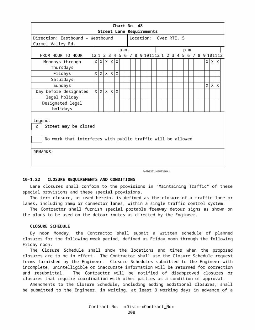
GENERALConcrete ditches, unless temporary, shall match the color of the precast concrete face elements of the Plantable
Geosynthetic Reinforced Wall, Bridge No. 57-1075.Shotcrete shall not be used as an alternative construction method for reinforced concrete members unless otherwise
specified.When a roughened concrete surface is shown on the plans, the existing concrete surface shall be roughened to a full
amplitude of approximately 6 mm by abrasive blasting, water blasting, or mechanical equipment.Neoprene strip shall be furnished and installed at abutment backwall joint protection and column isolation casing in
conformance with the details shown on the plans, the provisions in the Standard Specifications, and these special provisions.Furnishing and installing neoprene strip shall conform to the requirements for strip waterstops as provided in
Section 51-1.145, "Strip Waterstops," of the Standard Specifications, except that the protective board will not be required.Materials for access opening covers in soffits of new cast-in-place concrete box girder bridges shall conform to the
provisions for materials in Section 75-1.03, "Miscellaneous Bridge Metal," of the Standard Specifications.Vertical, horizontal, radial, or normal dimensions shown on the Typical Section in the plans, are for zero percent cross-
slope. At the Contractor's option, the Typical Section of superelevated concrete box girder structures with (1) sloping exterior girders, (2) a straight uninterrupted cross slope between edges of deck, and (3) a single profile grade line, may be rotated around the profile grade line in superelevation areas. The horizontal distances between the profile grade line and the edges of deck shall remain unchanged. The planned girder widths and slab thicknesses shall remain unchanged and the interior girder stems shall remain vertical at the planned locations.
FALSEWORKFalsework shall conform to the provisions in Section 51, "Concrete Structures," of the Standard Specifications and these
special provisions.Attention is directed to "Railroad Relations and Insurance" of these special provisions for additional requirements for
falsework over railroads.The first and second paragraph in Section 51-1.06A, "Falsework Design and Drawings," of the Standard Specifications
are amended to read:
The Contractor shall submit to the Engineer working drawings and design calculations for falsework proposed for use at bridges. For bridges where the height of any portion of the falsework, as measured from the ground line to the soffit of the superstructure, exceeds 4.25 m; or where any individual falsework clear span length exceeds 4.85 m; or where provision for vehicular, pedestrian, or railroad traffic through the falsework is made; the drawings shall be signed by an engineer who is registered as a Civil Engineer in the State of California. Six sets of the working drawings and 2 copies of the design calculations shall be furnished. Additional working drawings and design calculations shall be submitted to the Engineer when specified in "Railroad Relations and Insurance" of the special provisions.
The falsework drawings shall include details of the falsework erection and removal operations showing the methods and sequences of erection and removal and the equipment to be used. The details of the falsework erection and removal operations shall demonstrate the stability of all or any portions of the falsework during all stages of the erection and removal operations.
The seventh paragraph in Section 51-1.06A, "Falsework Design and Drawings," of the Standard Specifications is amended to read:
In the event that several falsework plans are submitted simultaneously, or an additional plan is submitted for review before the review of a previously submitted plan has been completed, the Contractor shall designate the sequence in which the plans are to be reviewed. In such event, the time to be provided for the review of any plan in the sequence shall be not less than the review time specified above for that plan, plus 2 weeks for each plan of higher priority which is still under review. A falsework plan submittal shall consist of plans for a single bridge or portion thereof. For multi-frame bridges, each frame shall require a separate falsework plan submittal.
Section 51-1.06A, "Falsework Design and Drawings," of the Standard Specifications is amended by adding the following paragraphs:
If structural composite lumber is proposed for use, the falsework drawings shall clearly identify the structural composite lumber members by grade (E value), species, and type. The Contractor shall provide technical data from the manufacturer showing the tabulated working stress values of the composite lumber. The Contractor shall furnish a certificate of compliance as specified in Section 6-1.07, "Certificates of Compliance," for each delivery of structural composite lumber to the project site.
Contract No. «Dist»-«Contract_No»211

For falsework piles with a calculated loading capacity greater than 900 kN, the falsework piles shall be designed by an engineer who is registered as either a Civil Engineer or a Geotechnical Engineer in the State of California, and the calculations shall be submitted to the Engineer.
The first paragraph in Section 51-1.06A(1), "Design Loads," of the Standard Specifications is amended to read:
The design load for falsework shall consist of the sum of dead and live vertical loads, and an assumed horizontal load. The minimum total design load for any falsework, including members that support walkways, shall be not less than 4800 N/m2 for the combined live and dead load regardless of slab thickness.
The eighth paragraph in Section 51-1.06A(1), "Design Loads," of the Standard Specifications is amended to read:
In addition to the minimum requirements specified in this Section 51-1.06A, falsework for box girder structures with internal falsework bracing systems using flexible members capable of withstanding tensile forces only, shall be designed to include the vertical effects caused by the elongation of the flexible member and the design horizontal load combined with the dead and live loads imposed by concrete placement for the girder stems and connected bottom slabs. Falsework comprised of individual steel towers with bracing systems using flexible members capable of withstanding tensile forces only to resist overturning, shall be exempt from these additional requirements.
The third paragraph in Section 51-1.06B, "Falsework Construction," of the Standard Specifications is amended to read:
When falsework is supported on piles, the piles shall be driven and the actual bearing value assessed in conformance with the provisions in Section 49, "Piling."
Section 51-1.06B, "Falsework Construction," of the Standard Specifications is amended by adding the following paragraphs:
For falsework piles with a calculated loading capacity greater than 900 kN, the Contractor shall conduct dynamic monitoring of pile driving and conduct penetration and bearing analyses based on a wave equation analysis. These analyses shall be signed by an engineer who is registered as a Civil Engineer in the State of California and submitted to the Engineer prior to completion of falsework erection.
Prior to the placement of falsework members above the stringers, the final bracing system for the falsework shall be installed.
Section 51-1.06C, "Removing Falsework," of the Standard Specifications is amended by adding the following paragraph:
The falsework removal operation shall be conducted in such a manner that any portion of the falsework not yet removed remains in a stable condition at all times.
In addition to the provisions in Section 51-1.06A, "Falsework Design and Drawings," of the Standard Specifications, the time to be provided for the Engineer's review of the working drawings for specific structures, or portions thereof, shall be as follows:
Structure or Portion of Structure Total Review Time - Weeks
Route 5/805 Separation (Widen),Bridge No. 57-0512
5
Sorrento Valley Viaduct (Widen),Bridge No. 57-0513R/L
9
S8/S805 Truck Connector,Bridge No. 57-1069F
5
Temporary crash cushion modules, as shown on the plans and conforming to the provisions in "Temporary Crash Cushion Module" of these special provisions, shall be installed at the approach end of temporary railings which are located less than 4.6 m from the edge of a traffic lane. For 2-way traffic openings, temporary crash cushion modules shall be installed at the departing end of temporary railings which are located less than 1.8 m from the edge of a traffic lane.
Contract No. «Dist»-«Contract_No»212
Welding and Nondestructive Testing Welding of steel members, except for when fillet welds are used where load demands are less than or equal to 175 N/mm
for each 3 mm of fillet weld, shall conform to AWS D1.1 or other recognized welding standard. The welding standard to be utilized shall be specified by the Contractor on the working drawings.
Splices made by field welding of steel beams at the project site shall undergo nondestructive testing (NDT). At the option of the Contractor, either ultrasonic testing (UT) or radiographic testing (RT) shall be used as the method of NDT for each field weld and any repair made to a previously welded splice in a steel beam. Testing shall be performed at locations selected by the Contractor. The length of a splice weld where NDT is to be performed, shall be a cumulative weld length equal to 25 percent of the original splice weld length. The cover pass shall be ground smooth at the locations to be tested. The acceptance criteria shall conform to the requirements of AWS D1.1, Section 6, for cyclically loaded nontubular connections subject to tensile stress. If repairs are required in a portion of the weld, additional NDT shall be performed on the repaired sections. The NDT method chosen shall be used for an entire splice evaluation including any required repairs.
For all field welded splices and previously welded splices, the Contractor shall furnish to the Engineer a letter of certification which certifies that all welding and NDT, including visual inspection, are in conformance with the specifications and the welding standard shown on the approved working drawings. The letter of certification shall be signed by an engineer who is registered as a Civil Engineer in the State of California and shall be provided prior to placing any concrete for which the falsework is being erected to support.
COST REDUCTION INCENTIVE PROPOSALS FOR CAST-IN-PLACE PRESTRESSED BOX GIRDER BRIDGESExcept as provided herein, cast-in-place prestressed box girder bridges shall be constructed in conformance with the
details shown on the plans and the provisions in Section 50, "Prestressing Concrete," and Section 51, "Concrete Structures," of the Standard Specifications.
If the Contractor submits cost reduction incentive proposals for cast-in-place prestressed box girder bridges, the proposals shall be in conformance with the provisions in Section 5-1.14, "Cost Reduction Incentive," of the Standard Specifications and these special provisions.
The Engineer may reject any proposal which, in the Engineer's judgment, may not produce a structure which is at least equivalent to the planned structure.
At the time the cost reduction incentive proposal (CRIP) is submitted to the Engineer, the Contractor shall also submit 4 sets of the proposed revisions to the contract plans, design calculations, and calculations from an independent checker for all changes involved in the proposal, including revisions in camber, predicted deck profile at each construction stage, and falsework requirements to the Office of Structure Design, Documents Unit, P.O. Box 942874, Sacramento, CA 94274-0001 (1801 30th Street, Sacramento, CA 95816), telephone (916) 227-8230. When notified in writing by the Engineer, the Contractor shall submit 12 sets of the CRIP plan revisions and calculations to the Office of Structure Design for final approval and use during construction. The calculations shall verify that all requirements are satisfied. The CRIP plans and calculations shall be signed by an engineer who is registered as a Civil Engineer in the State of California.
The CRIP plans shall be either 279 mm x 432 mm, or 559 mm x 864 mm in size. Each CRIP plan sheet and calculation sheet shall include the State assigned designations for the contract number, bridge number, full name of the structure as shown on the contract plans, and District-County-Route-Kilometer Post. Each CRIP plan sheet shall be numbered in the lower right hand corner and shall contain a blank space in the upper right hand corner for future contract sheet numbers.
Within 3 weeks after final approval of the CRIP plan sheets, one set of the corrected good quality prints on 75-g/m 2
(minimum) bond paper, 559 mm x 864 mm in size, of all CRIP plan sheets prepared by the Contractor for each CRIP shall be furnished to the Office of Structure Design, Documents Unit.
Each CRIP shall be submitted prior to completion of 25 percent of the contract working days and sufficiently in advance of the start of the work that is proposed to be revised by the CRIP to allow time for review by the Engineer and correction by the Contractor of the CRIP plans and calculations without delaying the work. The Contractor shall allow a minimum of 8 weeks for the review of a CRIP. In the event that several CRIPs are submitted simultaneously, or an additional CRIP is submitted for review before the review of a previously submitted CRIP has been completed, the Contractor shall designate the sequence in which the CRIPs are to be reviewed. In this event, the time to be provided for the review of any proposal in the sequence shall be not less than the review time specified herein for that proposal, plus 2 weeks for each CRIP of higher priority which is still under review.
Should the review not be complete by the date specified in the Contractor's CRIP, or such other date as the Engineer and Contractor may subsequently have agreed to in writing and if, in the opinion of the Engineer, the Contractor's controlling operation is delayed or interfered with by reason of the delay in review of CRIP plans and calculations, an extension of time commensurate with the delay in completion of the work thus caused will be granted as provided in Section 8-1.07, "Liquidated Damages," of the Standard Specifications except that the provisions in Section 8-1.09, "Right of Way Delays," of the Standard Specifications shall not apply.
Contract No. «Dist»-«Contract_No»213

Permits and approvals required of the State have been obtained for the structures shown on the plans. Proposals which result in a deviation in configuration may require new permits or approvals. The Contractor shall be responsible for obtaining the new permits and approvals before the Engineer will reach a decision on the proposal. Delays in obtaining permits and approvals will not be reason for granting an extension of contract time.
All proposed modifications shall be designed in conformance with the bridge design specifications and procedures currently employed by the Department. The proposal shall include all related, dependent or incidental changes to the structure and other work affected by the proposal. The proposal will be considered only when all aspects of the design changes are included for the entire structure. Changes, such as but not limited to, additional reinforcement and changes in location of reinforcement, necessary to implement the CRIP after approval by the Engineer, shall be made at the Contractor's expense.
Modifications may be proposed in (1) the thickness of girder stems and deck slabs, (2) the number of girders, (3) the deck overhang dimensions as specified herein, (4) the amount and location of reinforcing steel, (5) the amount and location of prestressing force in the superstructure, and (6) the number of hinges, except that the number of hinges shall not be increased. The strength of the concrete used may be increased but the strength employed for design or analysis shall not exceed 42 MPa.
Modifications proposed to the minimum amount of prestressing force which must be provided by full length draped tendons are subject to the provisions in "Prestressing Concrete" of these special provisions.
No modifications will be permitted in (1) the foundation type, (2) the span lengths or (3) the exterior dimensions of columns or bridge superstructure, except that the overhang dimension from face of exterior girder to the outside edge of roadway deck may be uniformly increased or decreased by 25 percent on each side of the box girder section. Fixed connections at the tops and bottoms of columns shown on the plans shall not be eliminated.
The Contractor shall be responsible for determining construction camber and obtaining the final profile grade as shown on the plans.
The Contractor shall reimburse the State for the actual cost of investigating CRIPs for cast-in-place prestressed box girder bridges submitted by the Contractor. The Department will deduct this cost from any moneys due, or that may become due the Contractor under the contract, regardless of whether or not the proposal is approved or rejected.
DECK CLOSURE POURSWhere a deck closure pour is shown on the plans, reinforcement protruding into the closure space and forms for the
closure pour shall conform to the following:
A. During the time of placement of concrete in the deck, other than for the closure pour itself, reinforcing steel which protrudes into the closure space shall be completely free from any connection to the reinforcing steel, concrete, or other attachments of the adjacent structure, including forms. The reinforcing steel shall remain free of any connection for a period of not less than 24 hours following completion of the pour.
B. Forms for the closure pour shall be supported from the superstructure on both sides of the closure space.
SLIDING BEARINGSSliding bearings consisting of elastomeric bearing pads lubricated with grease and covered with sheet metal shall
conform to the following requirements:
A. Grease shall conform to the requirements of Military Specification: MIL-S-8660. A uniform film of grease shall be applied to the upper surface of the pads prior to placing the sheet metal.
B. Sheet metal shall be commercial quality galvanized sheet steel. The sheet metal shall be smooth and free of kinks, bends, or burrs.
C. Construction methods and procedures shall prevent grout or concrete seepage into the sliding bearing assembly.
ELASTOMERIC BEARING PADSElastomeric bearing pads shall conform to the provisions in Section 51-1.12H, "Elastomeric Bearing Pads," of the
Standard Specifications.
10-1.57 PRECAST CONCRETE GIRDERSPrecast reinforced concrete girders shall conform to the provisions in Section 51, "Concrete Structures," of the Standard
Specifications.
Contract No. «Dist»-«Contract_No»214

PRECAST PRESTRESSED CONCRETE BRIDGE MEMBERSThe top surface of the member shall be given a coarse texture by brooming with a stiff bristled broom or by other
suitable devices that will result in uniform transverse scoring, in advance of curing operations. That portion of the top surface of box girders that is to be covered by expanded polystyrene shall be given a wood float finish. Remaining portions of the surface of the girders shall be given the coarse textured finish.
The anticipated deflection and method of accommodation of deflection of precast prestressed concrete girders, prior to the time the deck concrete is placed, shall be shown on the working drawings in conformance with the provisions in Section 5-1.02, "Plans and Working Drawings," of the Standard Specifications. The deflection shall include the following:
A. Anticipated upward deflection caused by the prestressing forces.B. Downward deflection caused by the dead load of the girder.C. Deflection caused by the creep and shrinkage of the concrete for the time interval between the stressing of the
girders and the planned placement of the deck.
Such deflection shall be substantiated by calculations that consider the ages of the girder concrete at the time of stressing and the Contractor's planned placement of the deck. All deflection calculations shall be based on the concrete producer's estimate of the modulus of elasticity at the applicable concrete age.
Adjustments to accommodate girder deflections, which occur prior to the time the deck concrete is placed, may include revisions in bearing seat elevations, but any such adjustments shall be limited by the following conditions:
A. The minimum permanent vertical clearance under the structure as shown on the plans shall not be reduced.B. The profile grade and cross slope of the deck shall not be changed.C. A minimum of 25 mm of deck slab concrete between the top of the precast girders and the deck slab reinforcement
shall be maintained.
Girders with unanticipated girder deflection and which cannot comply with conditions A, B, and C will be rejected in conformance with the provisions in Section 6-1.04, "Defective Materials," of the Standard Specifications.
Adjustments to accommodate girder deflections will not be considered a change in dimensions. Full compensation for increases in the cost of construction, including increases in the quantity of deck or bearing seat concrete, resulting from adjustments to accommodate girder deflections shall be considered as included in the contract price paid for the various items of work involved and no additional compensation will be allowed therefor.
Temporary lateral bracing shall be provided for girders located over the roadway at the Route 5/805 Separation, Bridge No. 57-0512. The bracing shall be installed at each end of each girder, except notched ends, prior to the release of the erection equipment from the girder and shall remain in place until 2 days after the concrete diaphragms have been placed. The bracing shall be adequate to prevent overturning of the girders prior to completion of the work and as a minimum shall be capable of resisting a lateral force of 720 Pa of girder side area applied laterally in either direction to the top of the girder. Girder erection shall not be started until the temporary lateral bracing proposed for use by the Contractor has been approved by the Engineer.
MEASUREMENT AND PAYMENTMeasurement and payment for concrete in structures shall conform to the provisions in Section 51-1.22, "Measurement,"
and Section 51-1.23, "Payment," of the Standard Specifications and these special provisions.Full compensation for roughening existing concrete surfaces to a full amplitude of approximately 6 mm, where shown on
the plans, shall be considered as included in the contract price paid per cubic meter for structural concrete, bridge and no separate payment will be made therefor.
Full compensation for furnishing and installing access opening covers in soffits of new cast-in-place box girder bridges shall be considered as included in the contract price paid per cubic meter for structural concrete, bridge and no separate payment will be made therefor.
10-1.58 PTFE BEARINGPTFE bearings, consisting of steel reinforced elastomeric bearing pads, polytetrafluoroethylene (PTFE) surfacing, and
stainless steel and steel plates, shall conform to the details shown on the plans, the provisions in Section 51, "Concrete Structures," of the Standard Specifications, and these special provisions.
The Contractor shall submit working drawings for the PTFE bearings to the Office of Structure Design, (OSD) for approval in conformance with the provisions in Section 5-1.02, "Plans and Working Drawings," of the Standard Specifications. For initial review, 6 sets of drawings shall be submitted for railroad bridges and 4 sets shall be submitted for other structures. After review, between 6 and 12 sets, as requested by the Engineer, shall be submitted to DSD for final approval and for use during construction.
Contract No. «Dist»-«Contract_No»215

Working drawings shall be 279 mm x 432 mm in size, and each drawing and calculation sheet shall include the name of the structure as shown on the contract plans, District-County-Route, bridge number, and contract number.
At the completion of each structure on the contract, one set of prints on 75-g/m2 (minimum) bond paper, 279 mm x 432 mm in size, of the corrected original tracings of all working drawings for each structure shall be furnished to the Engineer. Prints of drawings which are common to more than one structure shall be submitted for each structure. An index prepared specifically for the drawings for each structure containing sheet numbers and titles shall be included on the first print in the set for each structure. Prints for each structure shall be arranged in the order of drawing numbers shown in the index.
The edge of the corrected original tracing image shall be clearly visible and visually parallel with the edges of the page. A clear, legible symbol shall be provided as near to the upper left side of each page as is feasible within the original print to show the amount of reduction and a horizontal and vertical scale shall be provided on each reduced print to facilitate enlargement to original scale.
The manufacturer shall furnish Certificates of Compliance in conformance with the provisions in Section 6-1.07, "Certificates of Compliance," of the Standard Specifications, for all material used in the PTFE bearings.
The shear modulus of the elastomer in the elastomeric bearing pads shall be 750±75 kPa.PTFE sheet shall be made from unfilled PTFE resin and shall conform to the following requirements:
Test Test Method RequirementsTensile strength
(Minimum)ASTM D 4894 or
D 489519.3 MPa
Elongation (Minimum)
ASTM D 4894 or D 4895
200 %
The PTFE resin shall be virgin material (not reprocessed) meeting the requirements of ASTM Designation: D 4894 or D 4895, with a minimum thickness of 6 mm. Specific gravity shall be from 2.13 to 2.19. Melting point shall be 327±10°C.
The PTFE sliding surface shall be provided with lubricant dimples with a maximum diameter of 8 mm, a minimum depth of 2 mm, and a maximum depth of one half of the PTFE sheet thickness. The dimples shall be uniformly distributed within the area 6 mm from the edges of the PTFE sheet and occupy between 20 percent and 30 percent of the PTFE sheet area.
Stainless steel plates shall conform to the requirements of ASTM Designation: A 240, Type 304, with a minimum thickness of 3 mm.
Steel plates, except stainless steel, shall conform to the requirements of ASTM Designation: A 36/A 36M.Welding of structural steel shall conform to the requirements of AWS D1.1. Welding of structural steel to stainless steel
shall conform to the requirements of AWS D1.6.The PTFE sheet shall be adhesive bonded in the recess of steel plate under controlled factory conditions. The adhesive
material shall be an epoxy resin conforming to the requirements of Federal Specification: MMM-A-134.Contact surfaces of PTFE sheet and steel plate to be bonded shall be uniformly roughened to a minimum roughness
height value of 6.3 µm.The side of the PTFE sheet to be bonded shall be factory treated by the sodium naphthalene or sodium ammonia process,
after the contact surface is roughened.After completion of the bonding operation the PTFE surface shall be smooth and free from bubbles. The PTFE sheet
shall show no signs of delamination and shall be fully bonded within the recess.The stainless steel plate shall be attached by perimeter welding using Type 309L electrodes. After completion of the
weld operation, the stainless steel plate shall be smooth and free from waves.The flatness of the bearing elements shall be controlled such that upon completion of the bearing assembly, the
PTFE/stainless steel sliding interface shall be in full bearing.The mating surface of the stainless steel plate with the PTFE surfacing shall have a minimum #8 mirror finish
determined according to ANSI Standard B46.1. The sliding element of the production bearings shall have a first movement static coefficient of friction not exceeding 0.06 when tested without the coating of silicone grease.
Steel reinforced elastomeric bearing pads shall be fully vulcanized to the steel plates under factory controlled conditions, and the bond shall have a peel-strength of at least 5.3 Newtons per millimeter as determined by California Test 663.
Metal surfaces of bearings exposed to the atmosphere and in contact with the structure in the completed work, except stainless steel surfaces, shall be cleaned and painted in conformance with the provisions in Sections 59-2, "Painting Structural Steel," and 91, "Paint" of the Standard Specifications, and "Clean and Paint Structural Steel" of these special provisions.
Certification in conformance with the requirements in SSPC-QP 1, SSPC-QP 2, and SSPC-QP 3 of the "SSPC: The Society for Protective Coatings" will not be required for cleaning and painting PTFE bearings.
Finish coats will not be required on the bearings.
Contract No. «Dist»-«Contract_No»216

After installation, the top of the assembly shall be removed and a 1.5 mm thick coating of silicone grease shall be applied to the entire PTFE surface and the bearing reassembled without damage to the mating sliding surfaces. Silicone grease shall conform to the requirements in Military Specification: MIL-S-8660.
Damaged bearings and bearings with scratched mating surfaces shall be returned to the factory for replacement or resurfacing.
Prior to proof testing or painting, all individual components shall be permanently die-stamped on 2 of 4 sides with markings consisting of bearing number and contract number. Each bearing shall have a unique bearing number and match marks on plate edges to insure correct assembly at the job site.
Full sized PTFE bearings shall be proof tested and evaluated for compression and coefficient of initial static friction in the presence of the Engineer, unless otherwise directed. The proof tests shall be performed on samples randomly selected by the Engineer from the production bearings to be used in the work. Proof testing shall be performed by the Contractor at the manufacturer's plant or at an approved laboratory. If proof tests are not performed at the specified load, the Contractor shall perform additional physical tests in the presence of the Engineer, unless otherwise directed, to demonstrate that the requirements for proof testing at the specified load are satisfied. The Contractor shall give the Engineer at least 7 days notice before beginning proof testing. Proof testing of PTFE bearings shall conform to the following requirements:
A. One bearing per lot of production PTFE bearings shall be proof tested. A lot is defined as 25 PTFE bearings or fraction thereof of the same type, within a load category.
B. A load category shall consist of bearings of differing vertical load capacity within a range defined as follows:
1. Bearings with less than or equal to 2225 kN maximum vertical load capacity.2. Bearings with greater than 2225 kN but less than or equal to 8900 kN maximum vertical load capacity.3. Bearings with greater than 8900 kN maximum vertical load capacity.
C. Bearings shall be proof tested for compression and coefficient of friction.D. Proof tests for compression: The bearing shall be held for one hour at 1.5 times the maximum vertical load shown
on the plans for the bearing.E. Proof tests for coefficient of friction: The tests shall be performed at the minimum dead load shown on the plans for
the bearing with the test load applied for 12 hours continuously and the test load shall not be reduced or removed prior to friction measurement and the following:
1. The tests shall be arranged to allow measurement of the static coefficient of friction on the first movement of the bearing.
2. The first movement static and dynamic coefficients of friction shall be measured at a sliding speed not exceeding 25 millimeters per minute and shall not exceed the specified coefficient of initial static friction.
3. The test bearings shall be subjected to a minimum of 100 movements of at least 25 mm of relative movement at a sliding speed not exceeding 300 millimeters per minute. After cycling, the first movement static and dynamic coefficients of friction shall be measured again at a sliding speed not exceeding 25 millimeters per minute and shall not exceed the specified coefficient of initial static friction.
F. The bearing surfaces shall be cleaned prior to testing.G. Proof testing of bearings shall be done after conditioning specimens for 12 hours at 24°±3°C.H. The proof tested bearings shall show no visible sign of: (1) bond failure of bearing surfaces, (2) separation or lift-off
of plates from each other or from PTFE surfaces, (3) excessive transfer of PTFE to the stainless steel surface, or (4) other defects. When a proof tested bearing fails to comply with these specifications, all bearings in that lot shall be individually tested for acceptance.
I. Proof test results shall be certified correct and signed by the testing laboratory personnel who conducted the test and interpreted the test results. Proof test results shall include the bearing numbers of the bearings tested.
One sample of elastomeric bearing pad, 57±3 mm high and not less than 200 mm x 300 mm in plan, shall be cut by the manufacturer from one of the thickest production elastomeric bearing pads, as directed by the Engineer, and furnished to the Transportation Laboratory. The Contractor shall allow 3 weeks for testing and obtaining satisfactory results after the sample elastomeric bearing pad has been received.
A test specimen taken from the sample furnished to the Transportation Laboratory will be tested in conformance with the requirements in California Test 663 for 10,000 cycles at the design load and 1/2 T (T = total thickness of elastomer) translation. The testing speed shall not exceed 115 millimeters per minute. Specimens tested shall show no indication of deterioration of elastomer or loss of bond between the elastomer and steel laminates.
Contract No. «Dist»-«Contract_No»217

PTFE bearing sole plates shall be temporarily supported during concrete placement. Temporary supports shall prevent the rotation or displacement of the bearings during concrete placing operations. Temporary supports shall not inhibit the functioning of the PTFE bearings after concrete is placed. Temporary supports shall not restrict the movement at bridge joints due to temperature changes and shortening from prestress forces. Materials for temporary supports within the limits for placing concrete shall conform to the requirements for form fasteners.
PTFE and stainless steel surfaces shall be protected from contamination and weather damage.Quantities of PTFE bearings will be determined as units from actual count in the completed work. A PTFE bearing with
more than one disc shall be considered a single PTFE bearing.The contract unit price paid for PTFE bearing shall include full compensation for furnishing all labor, materials, tools,
equipment, and incidentals, and for doing all the work involved in constructing the bearing, complete in place, including temporary supports, proof testing, and cleaning and painting of PTFE bearings, as shown on the plans, as specified in the Standard Specifications and these special provisions, and as directed by the Engineer.
Full compensation for furnishing the sample of elastomeric bearing pad shall be considered as included in the contract unit price paid for PTFE bearing, and no separate payment will be made therefor.
If a portion or all of PTFE bearings are either fabricated or tested at a site more than 480 air line kilometers from both Sacramento and Los Angeles, additional shop inspection expenses will be sustained by the State. Whereas it is and will be impractical and extremely difficult to ascertain and determine the actual increase in such expenses, it is agreed that payment to the Contractor for PTFE bearings will be reduced $5,000 for each fabrication or testing site located more than 480 air line kilometers from both Sacramento and Los Angeles and an additional $10,000 ($15,000 total) for each fabrication or testing site located more than 4800 air line kilometers from both Sacramento and Los Angeles.
10-1.59 PTFE SPHERICAL BEARINGPTFE spherical bearings, consisting of polytetrafluoro-ethylene (PTFE) and stainless steel bearing surfaces, structural
steel plates and anchors shall conform to the details shown on the plans and these special provisions.PTFE spherical bearings shall be expansion type with spherical and sliding bearing surfaces.The manufacturer of the PTFE spherical bearings shall show evidence that PTFE spherical bearings furnished by the
same manufacturer and used in conditions similar to this application have had at least 3 years of satisfactory service at each of 2 projects.
A qualified representative of the manufacturer shall be present during installation of the first bearing and shall be available for advice during any remaining installations.
The working drawings for PTFE spherical bearings shall include a description of the method of mechanical interlocking of the PTFE fabric to the metallic substrate and details of temporary support for the PTFE bearing sole plate during concrete placement.
Working drawings shall be 279 mm x 432 mm or 559 mm x 864 mm in size and each drawing and calculation sheet shall include the name of the structure as shown on the contract plans, District-County-Route, bridge number, and contract number.
Working drawings shall be submitted sufficiently in advance of the start of the affected work to allow time for review by the Engineer and correction by the Contractor of the drawings without delaying the work. Such time shall be proportional to the complexity of the work but in no case shall such time be less 6 weeks for other structures after complete drawings and all support data are submitted.
At the completion of each structure on the contract, one set of reduced prints on 75-g/m2 (minimum) bond paper, 279 mm x 432 mm in size, of the corrected original tracings of all working drawings for each structure shall be furnished to the Engineer. Reduced prints of drawings which are common to more than one structure shall be submitted for each structure. An index prepared specifically for the drawings for each structure containing sheet numbers and titles shall be included on the first reduced print in the set for each structure. Reduced prints for each structure shall be arranged in the order of drawing numbers shown in the index.
The edge of the corrected original tracing image shall be clearly visible and visually parallel with the edges of the page. A clear, legible symbol shall be provided as near to the upper left side of each page as is feasible within the original print to show the amount of reduction and a horizontal and vertical scale shall be provided on each reduced print to facilitate enlargement to original scale.
PTFE spherical bearings shall be installed on surfaces prepared in conformance with the provisions in Section 55-3.19, "Bearings and Anchorages," of the Standard Specifications.
The manufacturer shall furnish certificates of compliance in conformance with the provisions in Section 6-1.07, "Certificates of Compliance," of the Standard Specifications for all material used in the PTFE spherical bearings. The certification shall be supported by a copy of the results of all proof tests performed on the bearings.
PTFE surfaces of PTFE spherical bearings shall be unfilled PTFE fabric made from virgin PTFE oriented multifilament and other fibers. The resin in the filaments shall be virgin PTFE material (not reprocessed) in conformance with the requirements of ASTM Designation: D 1457.
Contract No. «Dist»-«Contract_No»218

At the highest point of substrate and after compression, the PTFE fabric shall have a minimum thickness of 1.6 mm and a maximum thickness of 3.2 mm.
Flat stainless steel surfaces shall be a weld overlay on structural steel plate, or solid or sheet stainless steel conforming to the requirements of ASTM Designation: A 240, Type 304 with a minimum thickness of 1.5 mm.
Curved stainless steel surfaces shall be solid stainless steel conforming to the requirements of ASTM Designation: A 240, Type 304.
Curved stainless steel surfaces with dimensions shown on the plans exceeding 101.6 mm in thickness shall be either a weld overlay on structural steel plate or solid stainless steel conforming to the requirements of ASTM Designation: A 240, Type 304. Stainless steel sheet will not be allowed.
When a weld overlay is used for stainless steel surfacing, the overlay shall be placed by submerged arc welding using Type 309L electrodes. The finished overlay shall have a 2.38 mm minimum thickness after welding, grinding and polishing. Prior to welding, the manufacturer must submit a complete weld procedure to the Engineer for approval.
When stainless steel sheets are used for stainless steel surfacing, the sheets shall be attached by perimeter arc welding using Type 309L electrodes. After completion of the weld operation, the stainless steel surface shall be smooth and free from waves.
Structural steel plates, except stainless steel, shall conform to the requirements of ASTM Designation: A 709/A 709, Grade 36 [250], 50 [345], or 50W [345W].
Welding shall conform to the requirements of ANSI/AASHTO/AWS D1.5.Convex plate radius dimension tolerances shall be 0.000 to -250 µm. Concave plate radius dimensions shall be +250 to
0.000 µm.The bearing manufacturer shall have full size convex and concave metal templates for the 2 spherical surfaces of each
bearing radius. The templates shall be available to the inspector during all bearing inspections.The PTFE fabric on spherical or sliding bearing surfaces shall be epoxy bonded and mechanically interlocked to the steel
substrate. All bonding shall be done under controlled factory conditions. The mechanical interlock on the spherical concave surface must be integrally machined into the steel substrate. Welded retention grids will not be allowed on the concave surface. Any edges, other than the selvage shall be oversown or recessed so that no cut fabric edges are exposed.
After completion of the bonding operation the PTFE surface shall be smooth and free from bubbles.The surface of the bearing elements shall be controlled such that upon completion of the bearing assembly the PTFE to
stainless steel interface shall be in full bearing.The mating surface of the stainless steel with the PTFE surfacing shall have a polished surface finish of less than 0.5 µm
root-mean-square (rms), determined in conformance with the requirements in ANSI Standard B46.1.Metal surfaces of bearings exposed to the atmosphere in the completed work, except stainless steel surfaces shall be
cleaned and painted in conformance with the provisions in Sections 59-2, "Painting Structural Steel," and 91, "Paint" of the Standard Specifications, and "Clean and Paint Structural Steel" of these special provisions.
Certification in conformance with the requirements in SSPC-QP 1, SSPC-QP 2, and SSPC-QP 3 of the "SSPC: The Society for Protective Coatings" will not be required for PTFE spherical bearings.
Finish coats will not be required on the bearings.PTFE spherical bearing assemblies shall be assembled at the factory. Each assembly shall have a minimum of 4
temporary steel straps which are bolted to threaded holes in the masonry and sole plates so that the entire assembly is shipped as a unit and remains intact when uncrated and installed. Welding of the steel straps will not be allowed. Straps must be adequate for vertical lifting purposes. Bearing dismantling will only be allowed under the direction and in the presence of the Engineer.
During fabrication, the maximum temperature of bonded PTFE surfaces shall be 150°C.Damaged bearings and bearings with scratched mating surfaces shall be replaced or resurfaced.PTFE spherical bearing sole plates shall be temporarily supported during concrete placement. Temporary supports shall
prevent the rotation or displacement of the bearing during concrete placing operations. Temporary supports shall not inhibit the functioning of the PTFE spherical bearing after concrete is placed. Temporary supports shall not restrict the movement at bridge joints due to temperature changes and shortening from prestress forces. Materials for temporary supports within the limits for placing concrete shall conform to the requirements for form fasteners.
PTFE spherical bearings shall have a first movement static coefficient of friction not exceeding 0.06.Prior to proof testing, all bearings shall be permanently die-stamped on 2 of 4 sides with markings consisting of bearing
number and contract number. Each bearing shall have a unique bearing number and match marks on plate edges to insure correct assembly at the job site.
Full sized PTFE spherical bearings shall be proof tested and evaluated for compression and coefficient of friction in the presence of the Engineer, unless otherwise directed. The proof tests shall be performed on samples randomly selected by the Engineer from the production bearings to be used in the work. Proof testing shall be performed by the Contractor at the manufacturer's plant or at an approved laboratory. If proof tests are not performed at the specified load, the Contractor shall perform additional physical tests in the presence of the Engineer, unless otherwise directed, to demonstrate that the
Contract No. «Dist»-«Contract_No»219

requirements for proof testing at the specified load are satisfied. The Contractor shall give the Engineer at least 7 days notice before beginning proof testing. Proof testing of PTFE spherical bearings shall conform to the following requirements:
A. One bearing per lot of production bearings shall be proof tested. A lot is defined as 25 bearings or fraction thereof of the same type, within a load category.
B. The bearing types and proof tests required for each type shall be as follows:
Expansion type bearings shall be proof tested for compression and coefficient of friction.
C. A load category shall consist of bearings of differing vertical load capacity within a range defined as follows:
1. Bearings with less than or equal to 2225 kN maximum vertical load capacity.2. Bearings with greater than 2225 kN but less than or equal to 8900 kN maximum vertical load capacity.3. Bearings with more than 8900 kN maximum vertical load capacity.
D. Proof tests for compression: The bearing shall be held at the design rotation or 0.02 radians whichever is greater for one hour at 1.5 times the maximum vertical load shown on the plans for the bearing. The device shall be in a rotated position during the test. The rotation may be imposed on the bearing by inserting a beveled plate between the bearing and the restraining surface prior to loading.
E. Proof tests for coefficient of friction: The tests shall be performed at the maximum vertical load shown on the plans for the bearing with the test load applied for 12 hours prior to friction measurement and the following:
1. The tests shall be arranged to allow measurement of the static coefficient of friction on the first movement of the bearing.
2. The first movement static and dynamic coefficients of friction shall be measured at a sliding speed not exceeding 25 millimeter per minute and shall not exceed the specified coefficient of initial static friction.
3. The test bearings shall be subjected to a minimum of 100 movements of at least 25 mm of relative movement at a sliding speed not exceeding 300 millimeter per minute. After cycling, the first movement static and dynamic coefficients of friction shall be measured again at a sliding speed not exceeding 25 millimeter per minute and shall not exceed the specified coefficient of initial static friction.
F. The bearing surfaces shall be cleaned prior to proof testing.G. Proof testing of bearings shall be done after conditioning specimens for 12 hours at 21°±8°C.H. The proof tested bearings shall show no visible sign of: (1) bond failure of bearing surfaces, (2) separation or lift-off
of plates from each other or from PTFE surfaces, or (3) other defects. When a proof tested bearing fails to comply with these specifications, all bearings in that lot shall be individually tested for acceptance.
I. Proof test results shall be certified correct and signed by the testing laboratory personnel who conducted the test and interpreted the test results. Proof test results shall include the bearing numbers of the bearings tested.
Quantities of PTFE spherical bearings will be determined as units from actual count in the completed work. A PTFE spherical bearing with more than one PTFE surface shall be considered a single PTFE spherical bearing.
The contract unit price paid for PTFE spherical bearing shall include full compensation for furnishing all labor, materials, tools, equipment, and incidentals, and for doing all the work involved in constructing the bearing, complete in place, including masonry and sole plates, anchor bolts and sleeves, mortaring of bolts, temporary supports, proof testing, and cleaning and painting of PTFE spherical bearings, as shown on the plans, as specified in the Standard Specifications and these special provisions, and as directed by the Engineer.
If a portion or all of PTFE spherical bearings are either fabricated or tested at a site more than 480 air line kilometers from both Sacramento and Los Angeles, additional shop inspection expenses will be sustained by the State. Payment to the Contractor for furnishing PTFE spherical bearings will be reduced $5,000 for any fabrication and testing site located more than 480 air line kilometers from both Sacramento and Los Angeles, or in the case where a fabrication or testing site is located more than 4800 air line kilometers from both Sacramento and Los Angeles, payment will be reduced $15,000.
10-1.60 TYPE 6 RETAINING WALLType 6 retaining wall, consisting of a reinforced concrete footing and a reinforced concrete masonry unit stem, shall
conform to the provisions in Section 51, "Concrete Structures," and Section 52, "Reinforcement," of the Standard Specifications and these special provisions.
Wall stems may be constructed of reinforced concrete masonry units.
Contract No. «Dist»-«Contract_No»220

Hollow load-bearing concrete masonry units shall conform to the requirements in ASTM Designation: C 90, Type II and shall be of uniform color and size.
Portland cement for grout and mortar shall conform to Section 90-2.01, "Portland Cement," of the Standard Specifications or shall conform to the requirements in ASTM Designation: C 150, Type II.
Hydrated lime shall conform to the requirements in ASTM Designation: C 207, Type S.Mortar sand shall be commercial quality.Caulking, for sealing expansion joints, shall be a non-sag polysulfide or polyurethane material conforming to the
provisions in Federal Specification TT-S-230, Type II.Mortar for laying masonry units shall consist, by volume, of one part portland cement, 0 to 0.5 parts hydrated lime, and
2.25 to 3 parts mortar sand. Sufficient water shall be added to make a workable mortar. Each batch of mortar shall be accurately measured and thoroughly mixed. Mortar shall be freshly mixed as required. Mortar shall not be re-tempered more than one hour after mixing.
Aggregate for grout used to fill masonry units shall consist of fine aggregate and coarse aggregate conforming to the provisions in Section 90-2.02, "Aggregates," of the Standard Specifications. At least 20 percent of the aggregate by mass shall be coarse aggregate. The Contractor shall determine the grading except that between 90 percent and 100 percent of the combined grading shall pass the 12.5-mm sieve.
At the option of the Contractor, grout for filling masonry units may be proportioned either by volume or mass. Grout shall contain only enough water to cause it to flow and fill the voids without segregation. The maximum amount of free water shall not exceed 0.7 times the mass of the cement.
Grout proportioned by volume shall consist of at least one part portland cement and 4.5 parts aggregate. Aggregate volumes shall be based on a loose, air-dry condition.
Grout proportioned by mass shall contain at least 350 kg of portland cement per cubic meter.Concrete masonry unit construction shall be true and plumb. Recesses in the units for horizontal reinforcement shall be
provided.Cleanout openings shall be provided at the bottoms of all cells where the height of wall is in excess of 1.25 m. The
cleanouts shall be sealed before filling with grout, after inspection.Mortar joints shall be approximately 10 mm wide. Units shall be laid with full mortar coverage of the face in both the
vertical and horizontal joints, except where weep holes are specified. Vertical joints shall be shoved tight. Exposed joints shall be concave, tooled smooth.
All cells in the hollow unit masonry shall be filled solidly with grout. All grout shall be consolidated at the time of pouring by puddling or vibrating. The top lift of grout shall be placed approximately 25 mm below the top of the units, to provide for a cement mortar cap.
The cement mortar cap shall conform to the provisions for mortar.Splashing, staining or spotting on the exposed face of the wall stem shall be removed.Pay quantities of the reinforced concrete masonry unit stem for Type 6 retaining walls will be determined by the square
meter of completed wall stem, including the cap, measured along the horizontal length and the vertical height from the top of footing to the top of the wall.
The contract price paid per square meter for retaining wall (Masonry Wall) shall include full compensation for furnishing all labor, materials, (except reinforcement), tools, equipment, and incidentals, and for doing all the work involved in constructing the reinforced concrete masonry unit retaining wall stem, complete in place, as shown on the plans, as specified in the Standard Specifications and these special provisions, and as directed by the Engineer.
Measurement and payment of concrete for the footing and reinforcement for the footing and wall stem shall conform to the provisions in Section 51, "Concrete Structures," and Section 52, "Reinforcement," of the Standard Specifications.
10-1.61 STRUCTURE APPROACH SLABS (TYPE N) This work shall consist of constructing reinforced concrete approach slabs, structure approach drainage system, and
treated permeable base at structure approaches in conformance with the details shown on the plans, the provisions in Section 51, "Concrete Structures," of the Standard Specifications, and these special provisions.
GENERALAttention is directed to the section "Engineering Fabrics" of these special provisions.
STRUCTURE APPROACH DRAINAGE SYSTEMGeocomposite Drain
Geocomposite drain shall consist of a manufactured core not less than 6.35 mm thick nor more than 50 mm thick with one or both sides covered with a layer of filter fabric that will provide a drainage void. The drain shall produce a flow rate, through the drainage void, of at least 25 liters per minute per meter of width at a hydraulic gradient of 1.0 and a minimum
Contract No. «Dist»-«Contract_No»221

externally applied pressure of 168 kPa. Certificate of Compliance conforming to the provisions in Section 6-1.07, "Certificates of Compliance," of the Standard Specifications shall be furnished for the geocomposite drain certifying that the drain produces the required flow rate and complies with these special provisions. The Certificate of Compliance shall be accompanied by a flow capability graph for the geocomposite drain showing flow rates and the externally applied pressures and hydraulic gradients. The flow capability graph shall be stamped with the verification of an independent testing laboratory.
Filter fabric for the geocomposite drain shall conform to the provisions for fabric for underdrains in Section 88, "Engineering Fabrics," of the Standard Specifications.
The manufactured core shall be either a preformed grid of embossed plastic, a mat of random shapes of plastic fibers, a drainage net consisting of a uniform pattern of polymeric strands forming 2 sets of continuous flow channels, or a system of plastic pillars and interconnections forming a semirigid mat.
The core material and filter fabric shall be capable of maintaining the drainage void for the entire height of geocomposite drain. Filter fabric shall be integrally bonded to the side of the core material with the drainage void. Core material manufactured from impermeable plastic sheeting having nonconnecting corrugations shall be placed with the corrugations approximately perpendicular to the drainage collection system.
The geocomposite drain shall be installed with the drainage void and the filter fabric facing the embankment. The fabric facing the embankment side shall overlap a minimum of 75 mm at all joints and wrap around the exterior edges a minimum of 75 mm beyond the exterior edge. If additional fabric is needed to provide overlap at joints and wrap-around at edges, the added fabric shall overlap the fabric on the geocomposite drain at least 150 mm and be attached thereto.
Should the fabric on the geocomposite drain be torn or punctured, the damaged section shall be replaced completely or repaired by placing a piece of fabric that is large enough to cover the damaged area and provide a 150-mm overlap.
Plastic PipePlastic pipe shall conform to the provisions for pipe for edge drains and edge drain outlets in Section 68-3, "Edge
Drains," of the Standard Specifications.
Drainage PadsConcrete for use in drainage pads shall be minor concrete, except the concrete shall contain not less than 300 kilograms
of cement per cubic meter.
Treated Permeable Base At Bottom Of Geocomposite DrainsTreated permeable base to be placed around the slotted plastic pipe at the bottom of geocomposite drains shall conform
to the provisions in "Treated Permeable Base Under Approach Slabs." If asphalt treated permeable base is used, it shall be placed at a temperature of not less than 82°C nor more than 110°C.
The filter fabric to be placed over the treated permeable base at the bottom of geocomposite drains shall conform to the provisions for filter fabric for edge drains in Section 88, "Engineering Fabrics," of the Standard Specifications.
ENGINEERING FABRICSFilter fabric to be placed between the structure approach embankment material and the treated permeable base shall
conform to the provisions for filter fabric for edge drains in Section 88, "Engineering Fabrics," of the Standard Specifications and these special provisions.
The subgrade to receive the filter fabric, immediately prior to placing, shall conform to the compaction and elevation tolerance specified for the material involved.
Filter fabric shall be aligned, handled, and placed in a wrinkle-free manner in conformance with the manufacturer's recommendations.
Adjacent borders of the filter fabric shall be overlapped from 300 to 450 mm or stitched. The preceding roll shall overlap the following roll in the direction the material is being spread or shall be stitched. When the fabric is joined by stitching, it shall be stitched with yarn of a contrasting color. The size and composition of the yarn shall be as recommended by the fabric manufacturer. The stitches shall number 5 to 7 per 25 mm of seam.
Equipment or vehicles shall not be operated or driven directly on the filter fabric.
Woven tape fabric shall be treated to provide a minimum of 70 percent breaking strength retention after 500 hours exposure when tested in conformance with the requirements in ASTM Designation: D 4355. The Contractor shall notify the Engineer, in writing, of the source of woven tape fabric at least 45 days prior to use.
Contract No. «Dist»-«Contract_No»222

TREATED PERMEABLE BASE UNDER APPROACH SLABTreated permeable base under structure approach slabs shall consist of constructing either an asphalt treated permeable
base or a cement treated permeable base in accordance with Section 29, "Treated Permeable Bases," of the Standard Specifications and these special provisions.
The type of treatment, asphalt or cement, to be used shall be at the option of the Contractor.Not less than 30 days prior to the start of placing the treated permeable base, the Contractor shall notify the Engineer, in
writing, which type of treated permeable base will be furnished. Once the Contractor has notified the Engineer of the selection, the type to be furnished shall not be changed without a prior written request to do so and approval thereof in writing by the Engineer.
Asphalt treated permeable base shall be placed at a temperature of not less than 93°C nor more than 121°C. Material stored in excess of 2 hours shall not be used in the work.
Asphalt treated permeable base material may be spread in one layer. The base material shall be compacted with a vibrating shoe type compactor or rolled with a roller weighing not less than 1.3 tonnes nor more than 4.5 tonnes. Rolling shall begin as soon as the mixture has cooled sufficiently to support the weight of the rolling equipment without undue displacement.
Cement treated permeable base material may be spread in one layer. The base material shall be compacted with either a vibrating shoe type compactor or with a steel-drum roller weighing not less than 1.3 tonnes nor more than 4.5 tonnes. Compaction shall follow within one-half hour after the spreading operation and shall consist of 2-complete coverages of the treated material.
APPROACH SLABSConcrete for use in approach slabs shall contain not less than 400 kilograms of cement per cubic meter.Miscellaneous steel parts and all steel components of abutment ties including plates, nuts, washers, and rods shall
conform to the provisions in Section 75-1.03, "Miscellaneous Bridge Metal," of the Standard Specifications.Structure approach slabs shall be cured for not less than 5 days prior to opening to public traffic, unless, at the option of
the Contractor, the structure approach slabs and sleeper slabs are constructed using concrete with a non-chloride Type C chemical admixture conforming to these special provisions.
Portland cement for use in concrete using a non-chloride Type C chemical admixture shall be Type II Modified, Type II Prestress, or Type III. Type II Modified and Type III cement shall conform to the provisions in Section 90-2.01, "Portland Cement," of the Standard Specifications. Type II Prestress cement shall conform to the requirements of Type II Modified cement, except the mortar containing the portland cement to be used and Ottawa sand, when tested in conformance with California Test 527, shall not contract in air more than 0.053-percent.
The non-chloride Type C chemical admixture, approved by the Engineer, shall conform to the requirements in ASTM Designation: C 494 and Section 90-4, "Admixtures," of the Standard Specifications.
The concrete with non-chloride Type C chemical admixture shall be prequalified prior to placement in conformance with the provisions for prequalification of concrete specified by compressive strength in Section 90-9.01, "General," of the Standard Specifications and the following:
A. Immediately after fabrication of the 5 test cylinders, the cylinders shall be stored in a temperature medium of 21 ± 1.5°C until the cylinders are tested.
B. The 6-hour average strength of the 5 test cylinders shall not be less than 5.85 MPa. No more than 2 test cylinders shall have a strength of less than 5.5 MPa.
Building paper shall be commercial quality No. 30 asphalt felt.Polyvinyl chloride (PVC) conduit used to encase the abutment tie rod shall be of commercial quality.The top surface of approach slabs shall be finished in conformance with the provisions in Section 51-1.17, "Finishing
Bridge Decks," of the Standard Specifications. Edges of slabs shall be edger finished.Approach slabs shall be cured with pigmented curing compound (1) in conformance with the provisions for curing
structures in Section 90-7.01B, "Curing Compound Method," of the Standard Specifications.Structure approach slabs constructed using concrete with a non-chloride Type C chemical admixture shall be cured for
not less than 6 hours prior to opening to public traffic. The curing period shall be considered to begin at the start of discharge of the last truck load of concrete to be used in the slab.
If the ambient temperature is below 18°C during the curing period for approach slabs using concrete with a non-chloride Type C chemical admixture, an insulating layer or blanket shall cover the surface. The insulation layer or blanket shall have an R-value rating given in the table below. At the Contractor's option, a heating tent may be used in lieu of or in combination with the insulating layer or blanket.
Contract No. «Dist»-«Contract_No»223
Temperature range during curing period R-value, minimum13°C to 18°C 17°C to 13°C 24°C to 7°C 3
JOINTSHardboard and expanded polystyrene shall conform to the provisions in Section 51-1.12D, "Sheet Packing, Preformed
Pads and Board Fillers," of the Standard Specifications.Type AL joint seals shall conform to the provisions in Section 51-1.12F, "Sealed Joints" of the Standard Specifications.
The sealant may be mixed by hand-held power-driven agitators and placed by hand methods.The pourable seal between the steel angle and concrete barrier shall conform to the requirements for Type A and AL
seals in Section 51-1.12F(3), "Materials and Installation," of the Standard Specifications. The sealant may be mixed by hand-held power-driven agitators and placed by hand methods. Immediately prior to placing the seal, the joint shall be thoroughly cleaned, including abrasive blast cleaning of the concrete surfaces, so that all foreign material and concrete spillage are removed from all joint surfaces. Joint surfaces shall be dry at the time the seal is placed.
MEASUREMENT AND PAYMENTStructural concrete, approach slab (Type N) will be measured and paid for in conformance with the provisions in Section
51-1.22, "Measurement," and Section 51-1.23, "Payment," of the Standard Specifications and these special provisions.Full compensation for the structure approach drainage system including geocomposite drain, plastic pipe, drainage pads,
treated permeable base, filter fabric, miscellaneous metal, pourable seals, epoxy-coated bar reinforcement and epoxy-coated miscellaneous bridge metal, and waterstops, shall be considered as included in the contract price paid per cubic meter for structural concrete, approach slab of the type shown in the Engineer's Estimate and no additional compensation will be allowed therefor.
10-1.62 STRUCTURE APPROACH SLABS (TYPE R)Structure approach slabs (Type R) shall consist of removing portions of existing structures, existing pavement and base
including asphalt concrete surfacing, portland cement concrete pavement, subsealing material, and cement treated base and constructing new reinforced concrete approach slabs at structure approaches as shown on the plans and in conformance with these special provisions.
GENERALThe thickness shown on the plans for structure approach slabs is the minimum thickness. The thickness will vary
depending on the thickness of the pavement and base materials removed.Where pavement subsealing has been performed under existing approach slabs, the subsealing material shall be removed
for its full depth. Where removal of cement treated base is required to construct the approach slab, the entire thickness of the cement treated base shall be removed.
Voids between the new reinforced structure approach slab and the base material remaining in place that are caused by removal of subsealing material or cement treated base shall be filled, at the option of the Contractor, with aggregate base (approach slab) or structure approach slab concrete.
The Contractor shall establish a grade line for new approach slabs by setting stringlines on each side of the proposed approach slab. The stringlines shall start approximately 30 m from the structure and extend approximately 15 m onto the structure. The stringlines shall be adjusted as necessary to provide a smooth profile grade for the new approach slab. The profile grade will be subject to the approval of the Engineer.
The Contractor shall schedule his operations so that the pavement and base materials removed during a work period shall be replaced, in that same work period, with approach slab concrete that shall be cured for at least 6 hours prior to the time the lane is to be opened to public traffic as designated in "Maintaining Traffic" of these special provisions. In the event the existing pavement and base materials are removed and the Contractor is unable, as determined by the Engineer, to construct, finish and cure the new approach slab by the time the lane is to be opened to public traffic, the excavation shall be filled with a temporary roadway structural section as specified in this section, "Structure Approach Slabs (Type R)."
At locations where the removal of existing materials and approach slab construction is not required to be completed within the same work period, the requirements for "Temporary Roadway Structural Section" shall not apply. The Contractor shall have the option of:
A. Curing the approach slab concrete for not less than 5 days prior to opening to public traffic, orB. Constructing the approach slab using concrete with a non-chloride Type C chemical admixture and curing the
approach slab concrete at least 6 hours prior to opening to public traffic.Contract No. «Dist»-«Contract_No»
224

TEMPORARY ROADWAY STRUCTURAL SECTIONA sufficient standby quantity, as determined by the Engineer, of asphalt concrete and aggregate base shall be provided at
the project site for construction of a temporary roadway structural section where existing approaches to structures are being replaced. The temporary structural section shall be maintained and later removed as a first order of work when the Contractor is able to construct and cure the approach slab within the prescribed time limit. The temporary structural section shall consist of 90-mm thick layer of asphalt concrete over aggregate base.
The aggregate base for the temporary structural section shall conform to the requirements specified under "Aggregate Base (Approach Slab)" of these special provisions.
The asphalt concrete for the temporary structural section shall be produced from commercial quality aggregates and asphalt binder. The grading of the aggregate shall conform to the 19-mm maximum medium grading in Section 39-2.02, "Aggregate," of the Standard Specifications and the asphalt binder shall conform to the requirements of liquid asphalt SC-800 in Section 93, "Liquid Asphalts," of the Standard Specifications. The amount of asphalt binder to be mixed with the aggregate shall be approximately 0.3-percent less than the optimum bitumen content as determined by California Test 367.
Aggregate base and asphalt concrete for the temporary structural section shall be spread and compacted by methods that will produce a well-compacted, uniform base, free from pockets of coarse or fine material and a surfacing of uniform smoothness, texture, and density. The aggregate base and the asphalt concrete may each be spread and compacted in one layer. The finished surface of the asphalt concrete shall not vary more than 15 mm from the lower edge of a 3.6-m straightedge placed parallel with the centerline and shall match the elevation of the existing concrete pavement and structure along the joints between the existing pavement and structure and the temporary surfacing.
The material from the removed temporary structural section shall be disposed of outside the highway right of way in conformance with Section 7-1.13 of the Standard Specifications except that removed aggregate base may be stockpiled at the project site and reused for construction of another temporary structural section. When no longer required, standby material or stockpiled material for construction of temporary structural sections shall be removed and disposed of outside the highway right of way in conformance with the provisions in Section 7-1.13.
REMOVING PORTIONS OF EXISTING STRUCTURESAttention is directed to "Existing Highway Facilities" of these special provisions.
REMOVING EXISTING PAVEMENT AND BASE MATERIALSThe outline of portland cement concrete to be removed shall be sawed full depth with a power-driven concrete saw.The outlines of excavations in asphalt concrete shall be cut on a neat line to a minimum depth of 75 mm with a power-
driven concrete saw or wheel-type rock cutting excavator before any asphalt concrete material is removed. These excavations shall be permanently or temporarily backfilled to conform to the grade of the adjacent pavement prior to opening the lane to public traffic. Surplus excavated material may be used as temporary backfill material.
Regardless of the type of equipment used to remove concrete within the sawed outline, the surface of the concrete to be removed shall not be impacted within 0.5-m of the pavement to remain in place. Removing existing pavement and base materials shall be performed without damage to the adjacent structure or pavement that is to remain in place. Damage to the structure or to pavement that is to remain in place shall be repaired to a condition satisfactory to the Engineer. Damaged pavement shall be removed and replaced with new concrete pavement if ordered by the Engineer. Repairing damage to structures or repairing or removing and replacing damaged pavement outside the limits of structure approach slabs shall be at the Contractor's expense.
Materials removed shall be disposed of outside the highway right of way in conformance with the provisions in Section 7-1.13 of the Standard Specifications.
The base material remaining in-place, after removing the existing pavement and base materials to the required depth, shall be graded uniformly, watered, and compacted. The finished surface of the base material at any point shall not extend above the grade approved by the Engineer.
Areas of the base material that are low as a result of over excavation shall be filled, at the Contractor's expense, with structure approach slab concrete at the time and in the same operation that the new concrete is placed.
AGGREGATE BASE (APPROACH SLAB)The aggregate base (approach slab) for filling voids below the reinforced structure approach slab concrete shall be
produced from commercial quality aggregates consisting of broken stone, crushed gravel or natural rough-surfaced gravel, and sand, or any combination thereof. The grading of the aggregate base shall conform to the 19 -mm maximum grading specified in Section 26-1.02A, "Class 2 Aggregate Base," of the Standard Specifications.
Aggregate base (approach slab) for filling voids below the reinforced structure approach slab concrete shall be spread and compacted by methods that will produce a well-compacted, uniform base, free from pockets of coarse or fine material.
Contract No. «Dist»-«Contract_No»225

The aggregate base shall be watered and compacted to the grade approved by the Engineer. Where the required thickness of aggregate base is 200 mm or less, the base may be spread and compacted in one layer. Where the required thickness of aggregate base is more than 200 mm, the base shall be spread and compacted in 2 or more layers of approximately equal thickness. The maximum compacted thickness of any one layer shall not exceed 200 mm. The finished surface of the base material at any point shall not extend above the grade approved by the Engineer. Areas of the base material that are lower than the grade approved by the Engineer, shall be filled with structure approach slab concrete at the time and in the same operation that the new concrete is placed.
STRUCTURE APPROACH SLABReinforced concrete approach slabs shall conform to the provisions for approach slabs in Section 51, "Concrete
Structures," of the Standard Specifications and these special provisions.Concrete for use in approach slabs shall contain not less than 400 kg of cement per cubic meter.Miscellaneous steel parts and all steel components of abutment ties including plates, nuts, washers, and rods shall
conform to the provisions in Section 75-1.03, "Miscellaneous Bridge Metal," of the Standard Specifications.Approach slab concrete that requires a minimum curing period of 6 hours shall be constructed using a non-chloride Type
C chemical admixture. Mineral admixture will not be required in this concrete.Portland cement for use in concrete using a non-chloride Type C chemical admixture shall be Type II Modified, Type II
Prestress, or Type III. Type II Modified and Type III cement shall conform to the provisions in Section 90-2.01, "Portland Cement," of the Standard Specifications. Type II Prestress cement shall conform to the requirements of Type II Modified cement, except the mortar containing the portland cement to be used and Ottawa sand, when tested in conformance with California Test 527, shall not contract in air more than 0.053-percent.
The non-chloride Type C chemical admixture shall be approved by the Engineer and shall conform to the requirements in ASTM Designation: C 494 and Section 90-4, "Admixtures," of the Standard Specifications.
The concrete with non-chloride Type C chemical admixture shall be prequalified prior to placement in conformance with the provisions for prequalification of concrete specified by compressive strength in Section 90-9.01, "General," of the Standard Specifications and the following:
A. Immediately after fabrication of the 5 test cylinders, the cylinders shall be stored in a temperature medium of 21 ± 1.5°C until the cylinders are tested.
B. The 6-hour average strength of the 5 test cylinders shall not be less than 5.85 MPa. No more than 2 test cylinders shall have a strength of less than 5.5 MPa.
Building paper shall be commercial quality No. 30 asphalt felt.Polyvinyl chloride (PVC) conduit used to encase the abutment tie rod shall be commercial quality.Bar reinforcement or abutment tie rods in drilled holes shall be bonded in conformance with the provisions for drilling
and bonding dowels in Section 83-2.02D(1), "General," of the Standard Specifications.The top surface of approach slabs shall be finished in conformance with the provisions in Section 51-1.17, "Finishing
Bridge Decks," of the Standard Specifications. The finished top surface shall not vary more than 6 mm from the lower edge of a 3.6-m straightedge placed parallel with the centerline. Edges of slabs shall be edger finished.
The surface of the approach slab will not be profiled and the Profile Index requirements shall not apply.Approach slabs shall be cured with pigmented curing compound (1) in conformance with the provisions for curing
structures in Section 90-7.01B, "Curing Compound Method," of the Standard Specifications. The minimum curing period as specified in this section "Structure Approach Slabs (Type R)" shall be considered to begin at the start of discharge of the last truck load of concrete to be used in the slab. Fogging of the surface with water after the curing compound has been applied will not be required. Should the film of curing compound be damaged from any cause before the approach slab is opened to public traffic, the damaged portion shall be repaired immediately with additional compound, at the Contractor's expense. Damage to the curing compound after the approach slab is opened to public traffic shall not be repaired.
If the ambient temperature is below 18°C during the curing period, an insulating layer or blanket shall cover the surface. The insulation layer or blanket shall have an R-value rating given in the table below. At the Contractor's option, a heating tent may be used in lieu of or in combination with the insulating layer or blanket:
Temperature range during curing period R-value, minimum13°C to 18°C 17°C to 13°C 24°C to 7°C 3
Tests to determine the coefficient of friction of the final textured surface will be made only if the Engineer determines by visual inspection that the final texturing may not have produced a surface having the specified coefficient of friction. Tests to
Contract No. «Dist»-«Contract_No»226

determine the coefficient of friction will be made after the approach slab is opened to public traffic, but not later than 5 days after concrete placement. The coefficient of friction will be measured by California Test 342. Portions of completed concrete surfaces that are found to have a coefficient of friction less than 0.35 shall be ground or grooved parallel to the center line in conformance with the provisions for bridge decks in Section 42, "Groove and Grind Pavement," of the Standard Specifications.
JOINTSHardboard and expanded polystyrene shall conform to the provisions in Section 51-1.12D, "Sheet Packing, Preformed
Pads and Board Fillers," of the Standard Specifications.Type AL joint seals shall conform to the provisions in Section 51-1.12F, "Sealed Joints" of the Standard Specifications.
The sealant may be mixed by hand-held power-driven agitators and placed by hand methods.The pourable seal between the steel angle and concrete barrier shall conform to the requirements for Type A and AL
seals in Section 51-1.12F(3), "Materials and Installation," of the Standard Specifications. The sealant may be mixed by hand-held power-driven agitators and placed by hand methods. Immediately prior to placing the seal, the joint shall be thoroughly cleaned, including abrasive blast cleaning of the concrete surfaces, so that all foreign material and concrete spillage are removed from all joint surfaces. Joint surfaces shall be dry at the time the seal is placed.
MEASUREMENT AND PAYMENTStructural concrete, approach slab (Type R) will be measured and paid for in conformance with the provisions in Section
51-1.22, "Measurement," and Section 51-1.23, "Payment," of the Standard Specifications and these special provisions.Full compensation for removing and disposing of portions of existing structures and pavement materials, and for
furnishing and placing miscellaneous metal, Type AL joint seals, shall be considered as included in the contract price paid per cubic meter for structural concrete, approach slab (Type R) and no separate payment will be made therefor.
Full compensation for aggregate base (approach slab) shall be considered as included in the contract price paid per cubic meter for structural concrete, approach slab (Type R) and no separate payment will be allowed therefor.
Full compensation for furnishing, stockpiling, and disposing of standby material for construction of temporary structural sections; and for constructing, maintaining, removing, and disposing of temporary structural sections shall be considered as included in the contract price paid per cubic meter for structural concrete, approach slab (Type R) and no separate payment will be made therefor.
Full compensation for drilling and bonding of bar reinforcement or abutment tie rods shall be considered as included in the contract price paid per cubic meter for structural concrete, approach slab (Type R) and no separate payment will be made therefor.
10-1.63 PAVING NOTCH EXTENSIONThis work shall consist of extending existing paving notches in conformance with the details shown on the plans and
these special provisions.Concrete for paving notch extension shall be a high-strength material consisting of either magnesium phosphate
concrete, modified high alumina based concrete, or portland cement based concrete. Magnesium phosphate concrete shall conform to the provisions for magnesium phosphate concrete in Section 83-2.02D(1), "General," of the Standard Specifications and these special provisions. Modified high alumina based concrete and portland cement based concrete shall be water activated and shall conform to the provisions for single component (water activated) magnesium phosphate concrete in Section 83-2.02D(1), "General," of the Standard Specifications and these special provisions.
At least one hour shall elapse between the time of placing concrete for the paving notch extension and placing concrete for the structure approach slab.
A clean uniform rounded aggregate filler may be used to extend the concrete. The moisture content of the aggregate shall not exceed 0.5-percent. Grading of the aggregate shall conform to the following:
Sieve Sizes Percentage Passing12.5-mm 1001.18-mm 0-5
The amount of aggregate filler shall conform to the manufacturer's recommendation, but in no case shall the concrete strengths be less than that specified for magnesium phosphate concrete in Section 83-2.02D(1), "General," of the Standard Specifications.
The components of dual component (with a prepackaged liquid activator) magnesium phosphate shall be combined by mixing complete units supplied by the manufacturer. Portions of units shall not be used. Water shall not be added to dual component magnesium phosphate.
Contract No. «Dist»-«Contract_No»227

Magnesium phosphate concrete shall not be mixed in containers or worked with tools containing zinc, cadmium, aluminum or copper. Modified high alumina based concrete shall not be mixed in containers or worked with tools containing aluminum.
Concrete shall not be retempered. Finishing tools that are cleaned with water shall be thoroughly dried before working the concrete.
When placing concrete on slopes exceeding 5 percent, the Engineer may require the Contractor to provide a flow controlled modified material.
Modified high alumina based concrete and portland cement based concrete shall be cured in conformance with the provisions in Section 90-7.01B, "Curing Compound Method," of the Standard Specifications. Magnesium phosphate concrete shall not be cured.
The surface temperature of the areas to receive the concrete shall be 5°C or above when the concrete is placed. The contact surface to receive the magnesium phosphate concrete shall be dry. The contact surfaces to receive the modified high alumina concrete or portland cement based concrete may be damp but not saturated.
The construction joint between the paving notch extension and the existing abutment shall conform to the provisions for horizontal construction joints in Section 51-1.13, "Bonding," of the Standard Specifications. Concrete shall be placed in the spalled portions of the existing paving notch concurrently with the concrete for the paving notch extension.
Bar reinforcing steel shall conform to the provisions in Section 52, "Reinforcement," of the Standard Specifications.Structure excavation and backfill shall conform to the provisions in Section 19-3, "Structure Excavation and Backfill," of
the Standard Specifications.Drilling of holes and bonding of reinforcing steel dowels shall conform to the provisions for drilling and bonding dowels
in Section 83-2.02D(1), "General," of the Standard Specifications.The quantity of concrete for paving notch extension will be measured by the cubic meter as determined in conformance
with the dimensions shown on the plans or other dimensions that may be ordered in writing by the Engineer.The contract price paid per cubic meter for paving notch extension shall include full compensation for furnishing all
labor, materials (including concrete for the paving notch spalled areas), tools, equipment, and incidentals, and for doing all the work involved in constructing the paving notch extension, complete in place, including structure excavation and backfill, reinforcement, and drilling and bonding dowels, as shown on the plans, as specified in the Standard Specifications and these special provisions, and as directed by the Engineer.
10-1.64 SEALING JOINTSJoints in concrete bridge decks and joints between concrete structures and concrete approach slabs shall be sealed in
conformance with the details shown on the plans, the provisions in Section 51, "Concrete Structures," of the Standard Specifications, and these special provisions.
Where polyurethane seals are shown on the plans, a silicone sealant conforming to the provisions in Section 51–1.12F, "Sealed Joints," of the Standard Specifications may be used.
When ordered by the Engineer, a joint seal larger than called for by the Movement Rating shown on the plans shall be furnished and installed. Payment to the Contractor for furnishing the larger seal and for saw cutting the increment of additional depth of groove required will be determined as provided in Section 4-1.03, "Changes," of the Standard Specifications.
10-1.65 JOINT SEAL ASSEMBLIES (MAXIMUM MOVEMENT RATING, 100 mm)Joint seal assemblies shall conform to the details shown on the plans, the provisions in Section 51, "Concrete Structures,"
of the Standard Specifications, and these special provisions.All metal parts of the joint seal assembly shall conform to the provisions in Section 75-1.03, "Miscellaneous Bridge
Metal," of the Standard Specifications. Bolts, nuts, and washers shall conform to the requirements in ASTM Designation: A 325 or A 325M.
At the Contractor's option, cleaning and painting of all new metal surfaces of the joint seal assembly, except stainless steel and anchorages embedded in concrete, may be substituted for galvanizing. Cleaning and painting shall be in conformance with the provisions in "Clean and Paint Structural Steel" of these special provisions.
Certification in conformance with the requirements in SSPC-QP 1, SSPC-QP 2, and SSPC-QP 3 of the "SSPC: The Society for Protective Coatings" will not be required for cleaning and painting joint seal assemblies.
Finish coats will not be required on joint seal assemblies.Sheet neoprene shall conform to the provisions for neoprene in Section 51-1.14, "Waterstops," of the Standard
Specifications. The sheet neoprene shall be fabricated to fit the joint seal assembly accurately.Metal parts of the joint seal assembly shall be pre-assembled before installation to verify the geometry of the completed
seal.The bridge deck surface shall conform to the provisions in Section 51-1.17, "Finishing Bridge Decks," of the Standard
Specifications prior to placing and anchoring the joint seal assembly.Contract No. «Dist»-«Contract_No»
228

The assembly shall be placed in a blocked out recess in the concrete deck surface. The depth and width of the recess shall permit the installation of the assembly anchorage components or anchorage bearing surface to the lines and grades shown on the plans.
Contract No. «Dist»-«Contract_No»229

Sheet neoprene shall be installed at such time and in such manner that the sheet neoprene will not be damaged by construction operations. The joint shall be cleaned of all dirt, debris and other foreign material immediately prior to installation of the sheet neoprene.
ALTERNATIVE JOINT SEAL ASSEMBLYAt the Contractor's option, an alternative joint seal assembly may be furnished and installed provided: (1) that the
quality of the alternative and its suitability for the intended application are at least equal to that of the joint seal assembly shown on the plans, (2) that acceptable working drawings and a Certificate of Compliance are furnished as specified herein and (3) that the alternative conforms to the following requirements:
A. The determination as to the quality and suitability of a joint seal assembly will be made in the same manner as provided in Section 6-1.05, "Trade Names and Alternatives," of the Standard Specifications. The factors to be considered will include: the ability of the assembly to resist the intrusion of foreign material and water throughout the full range of movement for the application, and the ability to function without distress to any component.
B. Joint seal assemblies will not be considered for approval unless it can be proven that the assembly has had at least one year of satisfactory service under conditions similar to this application.
C. The Contractor shall submit complete working drawings for each joint seal assembly to the Division of Structure Design (DSD) in conformance with the provisions in Section 5-1.02, "Plans and Working Drawings," of the Standard Specifications. The working drawings shall show complete details of the joint seal assembly and anchorage components and the method of installation to be followed, including concrete blockout details and additions or rearrangements of the reinforcing steel from that shown on the plans. For initial review, 5 sets of working drawings shall be submitted. After review, between 6 and 12 sets of working drawings, as requested by the Engineer, shall be submitted to DSD for final approval and use during construction.
D. The working drawings shall be supplemented with calculations for each proposed joint seal assembly, as requested by the Engineer. Working drawings shall be either 279 mm x 432 mm or 559 mm x 864 mm in size. Each drawing and calculation sheet shall include the State assigned designations for the contract number, bridge number, full name of the structure as shown on the contract plans, and District-County-Route-Kilometer Post. The design firm's name, address, and telephone number shall be shown on the working drawings. Each sheet shall be numbered in the lower right hand corner and shall contain a blank space in the upper right hand corner for future contract sheet numbers.
E. Calculations, when requested, and working drawings, shall be stamped and signed by an engineer who is registered as a Civil Engineer. The Contractor shall allow the Engineer 4 weeks to review the drawings after a complete set has been received.
F. Within 3 weeks after final working drawing approval, one set of the corrected good quality prints on 75 g/m2
(minimum) bond paper (559 mm x 864 mm in size) of all working drawings prepared by the Contractor for each joint seal assembly shall be furnished to DSD.
G. Each shipment of joint seal materials shall be accompanied by a Certificate of Compliance in conformance with the provisions in Section 6-1.07, "Certificates of Compliance," of the Standard Specifications. The certificate shall state that the materials and fabrication involved comply in all respects to the specifications and data submitted in obtaining the approval.
H. The elastomer portion of the joint seal assembly shall be neoprene conforming to the requirements in Table 1 of ASTM Designation: D 2628 and the following, except that no recovery tests or compression-deflection tests will be required:
Property Requirement ASTM Test MethodHardness, Type A Durometer, points 55-70 D 2240 (Modified)Compression set, 70 hours at 100°C, maximum, percent
40 D 395 Method B (Modified)
I. All metal parts of an alternative joint seal assembly shall conform to the requirements above for the joint seal assembly shown on the plans. At the Contractor's option, metal parts may conform to the requirements in ASTM Designation: A 572/A 572M.
J. The assembly and its components shall be designed to support the AASHTO HS20-44 loading with 100 percent impact. The tire contact area used to distribute the tire loads shall be 244 mm, measured normal to the longitudinal axis of the assembly, by 508 mm wide. The assembly shall provide a smooth riding joint without slapping of components or wheel tire rumble.
Contract No. «Dist»-«Contract_No»230

K. The Movement Rating of the assembly shall be measured normal to the longitudinal axis of the assembly. The dimensions for positioning the assembly within the Movement Rating during installation shall be measured normal to the longitudinal axis, disregarding any skew of the deck expansion joint.
L. The assembly shall have cast-in-place anchorage components forming a mechanical connection between the joint components and the concrete deck.
Contract No. «Dist»-«Contract_No»231

M. The maximum depth and width of the recess shall be such that the primary reinforcement to provide the necessary strength of the structural members is outside the recess. The maximum depth of the recess at abutments and at hinges shall be 250 mm. The maximum width of the recess on each side of the expansion joint shall be 300 mm.
N. All reinforcement other than the primary reinforcement shall continue through the recess construction joint into the recess and engage the anchorage components of the assembly.
O. Horizontal angle points and vertical corners at curbs in assemblies shall consist of either pre-molded sections or standard sections of the joint seal assembly that have been specially miter cut or bent to fit the structure.
P. The elastomer portion of the assembly shall be installed in conformance with the manufacturer's recommendations at such time and in such a manner that the elastomer portion will not be damaged by construction operations. The joint and blockout shall be cleaned of all dirt, debris, and other foreign material immediately prior to the installation of the elastomer.
Full compensation for additional materials or work required because of the application of the optional cleaning and painting or the use of an alternative type joint seal assembly, shall be considered as included in the contract price paid per meter for the joint seal assembly involved and no additional compensation will be allowed therefor.
10-1.66 JOINT SEAL ASSEMBLIES (MOVEMENT RATING EXCEEDING 100 mm)Joint seal assemblies with movement ratings greater than 100 mm shall consist of a metal frame system, supporting rails
and support bars with intervening neoprene glands and shall conform to the details shown on the plans, the provisions in Section 51, "Concrete Structures," of the Standard Specifications and to these special provisions.
Joint seal assemblies will not be considered for approval without satisfactory evidence that the assemblies have had at least one year of satisfactory service under conditions similar to this application.
A qualified representative of the manufacturer shall be present during installation of the first assembly and shall be available for advice during any remaining installations.
The Contractor shall submit complete working drawings for each joint seal assembly to the Division of Structure Design (DSD) in conformance with the provisions in Section 5-1.02, "Plans and Working Drawings," of the Standard Specifications. The working drawings shall show complete details of the joint seal assembly and anchorage components and the method of installation to be followed, including concrete blockout details and any additions or rearrangements of the reinforcing steel from that shown on the plans. For initial review, 5 sets of drawings shall be submitted. After review, between 6 and 12 sets, as requested by the Engineer, shall be submitted to DSD for final approval and use during construction.
The working drawings shall be supplemented with complete calculations for the particular joint seal assembly, when requested by the Engineer. Working drawings shall be either 279 mm x 432 mm or 559 mm x 864 mm in size and each drawing and calculation sheet shall include the State assigned designations for the contract number, bridge number, full name of the structure as shown on the contract plans, and District-County-Route-Kilometer Post. The design firm's name, address, and phone number shall be shown on the working drawings. Each sheet shall be numbered in the lower right hand corner and shall contain a blank space in the upper right hand corner for future contract sheet numbers.
Calculations, when requested, and working drawings shall be stamped and signed by an engineer who is registered as a Civil Engineer. The Contractor shall allow the Engineer 4 weeks to review the drawings after a complete set has been received.
Within 3 weeks after final working drawing approval, one set of the corrected good quality prints on 75-g/m2 (minimum) bond paper (559 mm x 864 mm in size) of all working drawings prepared by the Contractor for each joint seal assembly shall be furnished to OSD.
Each shipment of joint seal assembly materials shall be accompanied by a Certificate of Compliance in conformance with the provisions in Section 6-l.07, "Certificates of Compliance," of the Standard Specifications. The certificate shall state that the materials and fabrication involved comply in all respects to the specifications and data submitted in obtaining approval.
The neoprene glands shall conform to the requirements in Table 1 of ASTM Designation: D 2628 and the following, except that no recovery tests or compression-deflection tests will be required:
Property Requirement ASTM Test Method
Hardness, Type A Durometer, points
55-70 D 2240 (Modified)
Compression set, 70 hours at 100°C,
maximum, percent
40 D 395 Method B (Modified)
Contract No. «Dist»-«Contract_No»232

All metal parts of the joint seal assembly shall conform to the provisions in Section 75-1.03, "Miscellaneous Bridge Metal," of the Standard Specifications. Bolts, nuts and washers shall conform to the requirements of ASTM Designation: A 325 or A 325M. At the Contractor's option, metal parts may conform to the requirements of ASTM Designation: A 572/A 572M.
At the Contractor's option, cleaning and painting of all new metal surfaces of the joint seal assembly, except stainless steel and anchorages embedded in concrete, may be substituted for galvanizing. Cleaning and painting shall be in conformance with the provisions in Sections 59-2, "Painting Structural Steel," and 91, "Paint," of the Standard Specifications, and "Clean and Paint Structural Steel" of these special provisions.
Certification in conformance with the requirements in SSPC-QP 1, SSPC-QP 2, and SSPC-QP 3 of the "SSPC: The Society for Protective Coatings" will not be required for cleaning and painting joint seal assemblies.
Finish coats will not be required on joint seal assemblies.If the assembly consists of more than one component, the design of the assembly shall be such that the external
components can be removed and reinstalled at any position, within the larger one-half of the movement rating shown on the plans, to permit the inspection of the internal components of the assembly.
Except for components in contact with the tires, the assembly and its components shall be designed to support the AASHTO HS20-44 loading with 100 percent impact. Each component in contact with the tires shall support a minimum of 80 percent of the AASHTO HS20-44 loading with 100 percent impact. The tire contact area used to distribute the tire loads shall be 244 mm, measured normal to the longitudinal axis of the assembly, by 508 mm wide. The assembly shall provide a smooth riding joint without slapping of components or wheel tire rumble.
The movement rating of the assembly shall be measured normal to the longitudinal axis of the assembly. The dimensions for positioning the assembly within the movement rating during installation shall be measured normal to the longitudinal axis, disregarding any skew of the deck expansion joint. The assembly shall be capable of adjustment to the "a" dimension shown on the plans.
The maximum width of unsupported or yielding components or grooves in the roadway surface of the assembly, measured in the direction of vehicular traffic, shall be 75 mm.
The bridge deck surface shall conform to the provisions in Section 51-1.17 "Finishing Bridge Deck," of the Standard Specifications prior to placing joint seal assemblies and anchorage.
The assembly shall be completely shop-assembled and placed in a blocked out recess in the concrete deck surface. The depth and width of the recess shall permit the installation of the assembly anchorage components or anchorage bearing surface to the planned line and grade.
The maximum depth and width of the recess shall be such that the primary reinforcement to provide the necessary strength of the structural members is outside the recess. The maximum depth of the recess at abutments and at hinges shall be 400 mm. The maximum width of recess on each side of the expansion joint shall be 700 mm.
All reinforcement other than primary reinforcement shall continue through the recess construction joint into the recess and engage the anchorage components of the assembly.
The vertical expansion joint in barrier shall be available for inspection after placement of the recess concrete around the anchorage components of the assembly.
The assembly shall make a watertight, continuous return 150 mm up into the barrier at the low side of the deck joint. Neoprene glands shall be continuous without field splices or joints, including the return up into barrier.
Full compensation for any additional materials or work required because of the application of the optional cleaning and painting shall be considered as included in the contract price paid per meter for the joint seal assembly involved, and no additional compensation will be allowed therefor.
10-1.67 ARCHITECTURAL SURFACE (TEXTURED CONCRETE)Architectural texture for concrete surfaces shall conform to the details shown on the plans and the provisions in
Section 51, "Concrete Structures," of the Standard Specifications and these special provisions.
Architectural textures listed below are required at concrete surfaces shown on the plans:
A. Fractured fin textureB. Heavy blast textureC. River Rock textureD. Stucco texture
The fractured fin texture shall be an architectural texture simulating the appearance of straight ribs of concrete with a fractured concrete texture imparted to the raised surface between the ribs. Grooves between ribs shall be continuous with no apparent curves or discontinuities. Variation of the groove from straightness shall not exceed 6 mm for each 3 m of groove. The architectural texture shall have random shadow patterns. Broken concrete at adjoining ribs and groups of ribs shall have
Contract No. «Dist»-«Contract_No»233

a random pattern. The architectural texture shall not have secondary patterns imparted by shadows or repetitive fractured surfaces.
The heavy blast texture shall be an architectural texture accomplished by abrasive blasting the surface of the concrete to produce a generally uniform color and sandy texture with air and water bubbles in the concrete partially exposed.
RIVER ROCK TEXTUREReferee panel for river rock texture, sample panel identified as "Sample Panel No. 3", may be inspected at the Office of
Landscape Architecture, 2829 Juan Street, San Diego, California 92110.Staining of the river rock texture shall be achieved by applying stains to the stone surfaces as described in "Prepare and
Stain Concrete," elsewhere in these special provisions. The stone shall be randomly stained light brown and grey colors to match Sample Panel No. 3.
River rock texture shall be obtained by using form liners as described below:
Reusable form liners hall be capable of as many as 40 reuses. The form liners shall release without leaving particles of pieces of liner material on the concrete and without puling or breaking concrete from the textured surface.
The form liner shall be either of the following materials:
An elastomeric material having a Shore A Hardness between 40 and 65 (ASTM Designation: D2240) and a tensile strength between 900 and 6206 kPa (ASTM Designation: D412). Liner shall have a self-contained release agent good for a minimum of 40 to 50 releases. Thereafter a conditioner may be used to extend the re-use factor.
A plasticized polyvinyl chloride with a maximum Shore A Hardness of 20 - 30 (ASTM Designation: D2240) and a tensile strength maximum of 1000 kPa (ASTM Designation: D412). Liner shall have a self-contained release agent good for a minimum of 40 to 50 releases. Thereafter a conditioner may be used to extend the re-use factor.
Prior to constructing a test panel, a sample of form liner (approximately 1.22 meter by 1.22 meter) to be used in constructing the river rock texture shall be submitted to the Engineer for approval.
The river rock pattern shall be arranged such that no partial stones exist at the edge of the form liner panel, except at the top of the wall.
The textured surface shall be given a Class 1 surface finish and then lightly sandblasted to remove any surface sheen the form liner may cause. All loose material, laitance, efflorescence and other foreign materials shall be removed from the surface.
Form liners shall be bonded to 19 mm A-B exterior grade plywood to provide a rigid panel and reduce surface deflection.
Form liners shall be full height of texturing with vertical splices permitted at 2.44 meter minimum spacing. Adjoining liners shall be butted tightly together. Open cracks shall be filled.
Concrete for all walls requiring this pattern, whether precast or cast-in-place, shall be poured monolithically. Finished panels shall not have any repetitious surface undulations that are visible as horizontal demarcations when panels are in the erected position.
Cement and aggregate used in the construction of walls to received river rock texture shall be consistent throughout the job and periodically sampled for comparison of color and gradation with the material used in the test panel.
Areas to receive surface texture that do not exhibit the surface specified shall be replaced so as to exhibit the specified texture. Acceptability will be determined by the Engineer.
The finished work shall be protected during the remainder of the construction process. Damaged areas shall be replaced.
TEST PANELA test panel at least 1.25 m x 1.25 m in size shall be successfully completed at a location approved by the Engineer
before beginning work on architectural textures. The test panel shall be constructed and finished with the materials, tools, equipment and methods to be used in constructing the architectural texture. If ordered by the Engineer, additional test panels shall be constructed and finished until the specified finish, texture and color are obtained, as determined by the Engineer.
The test panel approved by the Engineer shall be used as the standard of comparison in determining acceptability of architectural texture for concrete surfaces.
CURINGConcrete surfaces with architectural texture shall be cured only by the forms-in-place or water methods. Unless
otherwise specified, seals and curing compounds shall not be used.
Contract No. «Dist»-«Contract_No»234

STUCCO TEXTURE This work shall consist of applying portland cement plaster in accordance with the details shown on the plans and these
special provisions.Plaster shall be 2 coat work. The total thickness of plaster shall be 19 mm unless otherwise shown on the plans.
BROWN COAT
A. After preparation is completed the surface shall be coated with a 13 mm washed sand and portland cement mix, brown in color.
B. The brown coat shall be allowed to cure for a minimum of 48 hours prior to application of a texture coat.
TEXTURE COAT
A. The texture coat shall be Mission Tan in color. The Contractor shall match the finish of retaining walls 3A, 4, 5, 6, & 7 to that of the existing walls on the north side of Carmel Mountain Road.
PRODUCTS.--
Sand.--Sand shall be lean commercial quality plaster sand.
Cement.--Cement shall be portland cement, blended hydraulic cement, or portland cement with a maximum of 15 percent mineral admixture. Portland cement shall be Type II, conforming to ASTM Designation: C 150. Blended hydraulic cement shall be Type IP, conforming to ASTM Designation: C 595. Mineral admixture shall be Class N, Class F or Class C, conforming to ASTM Designation: C 618, except loss on ignition shall not exceed 4 percent.
Lime.--Lime shall conform to ASTM Designation: C 206.
Color for plaster.--Color for plaster shall be non-fading, sunproof, and limeproof fine ground synthetic mineral oxide.
AdhesiveAdhesive for bonding portland cement plaster to retaining walls shall be a commercially available acrylic adhesive.
Premixed portland cement plaster.--Premixed portland cement plaster shall be a premixed packaged blend of cement, lime and sand, with or without color, that requires only water to prepare for use as portland cement plaster, may be furnished. Premixed plaster shall be proportioned as specified herein. Packages of premix shall bear the manufacturer's name, brand, weight and color identification.
Water.--Water shall be potable.
PLASTER PROPORTIONING AND MIXINGMaterials shall be accurately proportioned and measured for each batch. All batches for a given coat shall be
proportioned the same. Plaster shall be proportioned one part cement to between 3 and 5 parts sand by volume, only sufficient water to obtain a workable mix, and a lime plasticizing agent. Not more than 9 kg of dry hydrated lime or lime putty per sack of cement shall be used in the brown coat. Plaster for texture coat shall contain not more than 42 kg of dry hydrated lime or lime putty per sack of cement. Lime shall not be used if mineral admixture or blended hydraulic cement is used.
Frozen materials shall not be used in the mix.All plaster mixing ingredients shall be mixed in a mechanical mixer. After all ingredients are in the mixer, the plaster
shall be mixed for a minimum of 2 minutes. The mixture shall be uniform in color after mixing. Hand mixing of plaster will
Contract No. «Dist»-«Contract_No»235

be allowed only with the written approval of the Engineer.Plaster to be colored shall be colored by mixing the coloring ingredient uniformly and homogeneously into the plaster.
Color will be required only in materials for the texture coat.
PLASTER APPLICATIONPlaster shall not be applied if the ambient temperature is 4°C or less. Plaster shall not be applied to frost covered or
frozen surfaces. Surfaces to receive plaster shall be clean.The brown coat shall be applied continuously in one general direction without allowing mortar to dry at the edges.The brown coat shall be applied with sufficient material and pressure to form full keys and good bond and to cover
surfaces.The brown coat of plaster shall be brought out to grounds, straightened to a true, even surface, roughened to assure a
bond with the texture coat, and made free of imperfections which would reflect in the texture coat. The brown coat shall be moisture cured, without soaking, for not less than 48 hours after application.
The texture coat of plaster shall not be placed until at least 7 days after the brown coat of plaster has been placed. Troweling of the texture coat of plaster shall leave the surface smooth and free from rough areas, trowel marks, checks, or other blemishes. The finished surface shall be true and even and shall not vary more than 3 millimeters in 1.5 meters from the required plane. Plaster with cracks, blisters, pits, stains, efflorescence, shadowing, dryouts, or checks will not be accepted. Surfaces shall be clean and sound.
The texture coat shall have the type of finish shown on the plans.After all other related work has been completed, pointing around trim and set work and repairing of damaged portions of
plaster shall be done. Repairs and patching shall match surrounding work in texture and appearance.Plaster coats shall be protected against freezing for a period of 24 hours after application.
MEASUREMENT AND PAYMENTArchitectural texture will be measured and paid for by the square meter.The contract price paid per square meter for architectural texture of the types listed in the Engineer's Estimate shall
include full compensation for furnishing all labor, materials, tools, equipment, and incidentals and for doing all the work involved in architectural texture, complete in place, including test panels, as shown on the plans, as specified in the Standard Specifications and these special provisions, and as directed by the Engineer.
10-1.68 DRILL AND BOND DOWELSDrilling and bonding dowels shall conform to the details shown on the plans, the provisions in Section 83-2.02D(1),
"General," of the Standard Specifications, and these special provisions.Dowels shall conform to the provisions for bar reinforcement in "Reinforcement" of these special provisions.If reinforcement is encountered during drilling before the specified depth is attained, the Engineer shall be notified.
Unless the Engineer approves coring through the reinforcement, the hole will be rejected and a new hole, in which reinforcement is not encountered, shall be drilled adjacent to the rejected hole to the depth shown on the plans.
Unless otherwise provided, dowels to be bonded into drilled holes will be paid for as bar reinforcing steel (bridge).Unless otherwise provided, drilling and bonding dowels will be measured and paid for by the meter determined by the
number and the required depth of holes as shown on the plans or as ordered by the Engineer.The contract price paid per meter for drill and bond dowel shall include full compensation for furnishing all labor,
materials (except reinforcing steel dowels), tools, equipment, and incidentals, and for doing all the work involved in drilling the holes, including coring through reinforcement when approved by the Engineer, and bonding the dowels, complete in place, as shown on the plans, as specified in the Standard Specifications and these special provisions, and as directed by the Engineer.
10-1.69 REINFORCEMENTReinforcement shall conform to the provisions in Section 52, "Reinforcement," of the Standard Specifications and these
special provisions.The third paragraph in Section 52-1.04, "Inspection," of the Standard Specifications is amended to read:
A Certificate of Compliance conforming to the provisions in Section 6-1.07, "Certificates of Compliance," shall also be furnished for each shipment of epoxy-coated bar reinforcement or wire reinforcement certifying that the coated reinforcement conforms to the requirements in ASTM Designation: A 775/A 775M or A 884/A 884M, respectively, and the provisions in Section 52-1.02B, "Epoxy-coated Reinforcement." The Certificate of Compliance shall include all of the certifications specified in ASTM Designation: A 775/A 775M or A 884/A 884M respectively, and a statement that the
Contract No. «Dist»-«Contract_No»236

coating material has been prequalified by acceptance testing performed by the Valley Forge Laboratories, Inc., Devon, Pennsylvania.
The third paragraph in Section 52-1.08C, "Mechanical Butt Splices," of the Standard Specifications is amended to read:
The total slip of the reinforcing bars within the splice sleeve after loading in tension to 200 MPa and relaxing to 20 MPa shall not exceed the values listed in the following table. The slip shall be measured between gage points that are clear of the splice sleeve.
Reinforcing Bar Number Total Slip (µm)13 25016 25019 25022 35025 35029 35032 45036 45043 60057 750
The first paragraph in Section 52-1.08C(5), "Sleeve-Lockshear Bolt Mechanical Butt Splices," of the Standard Specifications is amended to read:
The sleeve-lockshear bolt type of mechanical butt splices shall consist of a seamless steel sleeve, center hole with centering pin, and bolts that are tightened until the bolt heads shear off with the bolt ends left embedded in the reinforcing bars. The seamless steel sleeve shall be either formed into a V configuration or shall have 2 serrated steel strips welded to the inside of the sleeve.
Section 52-1.08F, "Nondestructive Splice Tests," of the Standard Specifications is amended by deleting the seventh paragraph.
Individual hoops, made continuous with butt welded splices, which are substituted for spiral reinforcement, shall conform to the requirements for "Ultimate Butt Splices" of these special provisions.
ULTIMATE BUTT SPLICESUltimate butt splices shall be either welded or mechanical splices, shall be used at the locations shown on the plans, and
shall conform to the provisions in Section 52, "Reinforcement," of the Standard Specifications and these special provisions.
General RequirementsThe Contractor shall designate in writing an ultimate butt splicing Quality Control Manager (QCM). The QCM shall be
responsible directly to the Contractor for 1) the quality of all ultimate butt splicing including the inspection of materials and workmanship performed by the Contractor and all subcontractors; and 2) submitting, receiving, and approving all correspondence, required submittals, and reports regarding ultimate butt splicing to and from the Engineer.
The QCM shall not be employed or compensated by any subcontractor, or by other persons or entities hired by subcontractors, who will provide other services or materials for the project. The QCM may be an employee of the Contractor.
The length of any type of ultimate mechanical butt splice shall not exceed 10 times the bar diameter of the larger bar to be spliced.
All ultimate prejob, production, and job control sample splices shall be 1) a minimum length of 1.5 meters for reinforcing bars No. 25 or smaller and 2 meters for reinforcing bars No. 29 or larger, with the splice located at mid-point, and 2) suitably identified prior to shipment with weatherproof markings that do not interfere with the Engineer's tamper-proof markings or seals. Any splice that shows signs of tampering will be rejected.
A minimum of one control bar shall be removed from the same bar as, and adjacent to, all ultimate prejob, production, and job control sample splices. Control bars shall be 1) a minimum length of one meter for reinforcing bars No. 25 or smaller and 1.5 meters for reinforcing bars No. 29 or larger, and 2) suitably identified prior to shipment with weatherproof markings that do not interfere with the Engineer's tamper-proof markings or seals. The portion of adjacent bar remaining in the work shall also be identified with weatherproof markings that correspond to its adjacent control bar.
Contract No. «Dist»-«Contract_No»237

Shorter length sample splice and control bars may be furnished if approved in writing by the Engineer.Each sample splice and its associated control bar shall be identified and marked as a set. Each set shall be identified as
representing a prejob, production, or job control sample splice.The portion of hoop reinforcing bar, removed to obtain a sample splice and control bar, shall be replaced using a
prequalified ultimate mechanical butt splice, or the hoop shall be replaced in kind.Reinforcing bars, other than hoops, from which sample splices are removed, shall be repaired using ultimate mechanical
butt splices conforming to the provisions in "Prejob Test Requirements for Ultimate Butt Splices" specified herein, or the bars shall be replaced in kind. These bars shall be repaired or replaced such that no splices are located in the "No Splice Zone" shown on the plans.
Section 52-1.08E, "Job Control Tests," of the Standard Specifications shall not apply.The provisions for total slip shall not apply to any ultimate splices that are welded or that are used on hoops.The independent qualified testing laboratory used to perform the testing of all ultimate butt sample splices and control
bars shall not be employed or compensated by any subcontractor, or by other persons or entities hired by subcontractors who will provide other services or materials for the project, and shall have the following:
A. Proper facilities, including a tensile testing machine capable of breaking the largest size of reinforcing bar to be tested.
B. A device for measuring the total slip of the reinforcing bars across the splice to the nearest 25 µm, that, when placed parallel to the longitudinal axis of the bar is able to simultaneously measure movement across the splice, at 2 locations, 180 degrees apart.
C. Operators who have received formal training for performing the testing requirements of ASTM Designation: A 370/A 370M and California Test 670.
D. A record of annual calibration of testing equipment performed by an independent third party that has 1) standards that are traceable to the National Institute of Standards and Technology, and 2) a formal reporting procedure, including published test forms.
Ultimate Butt Splice Test CriteriaUltimate prejob, production, and job control sample splices shall be tensile tested in conformance with the requirements
described in ASTM Designation: A 370/A 370M and California Test 670.Ultimate prejob and production sample splices shall rupture in the reinforcing bar either: 1) outside of the affected zone
or 2) within the affected zone, provided that the sample has achieved at least 95 percent of the ultimate tensile strength of the control bar associated with the sample. In addition, necking of the bar shall be visibly evident at rupture regardless of whether the bar breaks inside or outside the affected zone.
The affected zone is the portion of the reinforcing bar where any properties of the bar, including the physical, metallurgical, or material characteristics, have been altered by fabrication or installation of the splice.
The ultimate tensile strength of each control bar shall be determined by tensile testing the bar to rupture and shall be determined for all control bars, regardless of where each sample splice ruptures. If 2 control bars are tested for one sample splice, the bar with the lower ultimate tensile strength shall be considered the control bar.
Testing to determine the minimum tensile strength, in conformance with the provisions in the ninth paragraph of Section 52-1.08, "Splicing," of the Standard Specifications, will not be required.
Prejob Test Requirements for Ultimate Butt SplicesPrior to use in the work, all ultimate butt splices shall conform to the following prejob test requirements:
A. Eight prejob sample splices for each bar size of each splice type including ultimate mechanical butt splices, ultimate complete joint penetration butt welded splices, and ultimate resistance butt welded splices, that will be used in the work, shall be fabricated by the Contractor. For deformation-dependent types of couplers, 8 sample prejob splices shall also be fabricated for each reinforcing bar size and deformation pattern that will be used in the work.
B. The sample splices shall be fabricated using the same splice materials, position, operators, location, and equipment, and following the same procedures as will be used to make the splices in the work. In addition, for resistance butt welded splices, the sample splices shall have the weld flash removed and be epoxy-coated as specified elsewhere in these special provisions.
C. At the option of the Contractor, operator qualification tests may be performed simultaneously with the preparation of prejob sample splices.
D. If different diameters of hoops are shown on the plans, prejob sample splices, as described above, will only be required for the smallest hoop diameter. In addition, these splices shall be fabricated using the same radius as shown on the plans for these hoops.
Contract No. «Dist»-«Contract_No»238

E. Unless otherwise directed in writing by the Engineer, 4 prejob sample splices and control bar sets shall be shipped to the Transportation Laboratory and the remaining 4 sets shall be tested by the Contractor's independent qualified testing laboratory.
F. Each group of 4 sets from a prejob test shall be securely bundled together and identified by location and contract number with weatherproof markings prior to shipment. Bundles containing fewer than 4 sets will not be tested by the Transportation Laboratory, nor shall they be tested by the independent laboratory.
G. All 8 sample splices from each prejob test shall conform to the provisions in "Ultimate Butt Splice Test Criteria" specified herein.
H. Prior to performing any tensile tests on prejob test sample splices, one of the 4 samples shall be tested for, and shall conform to, the provisions for total slip. Should this sample not meet these requirements, one retest, in which the 3 remaining samples are tested for total slip, will be allowed. All 3 of these remaining samples tested shall conform to the aforementioned slip requirements.
I. For each bundle of 4 sets, a Prejob Test Report shall be prepared by the independent testing laboratory performing the testing. The report shall 1) be signed by an engineer who represents the laboratory and is registered as a Civil Engineer in the State of California; 2) include, as a minimum, the following information for each set: contract number, bridge number, bar size, type of splice, length of mechanical splice, physical condition of test sample splice and control bar, any notable defects, limits of affected zone, total measured slip, location of visible necking area, ultimate strength of each splice, ultimate strength and 95 percent of this ultimate strength for each control bar, and a comparison between 95 percent of the ultimate strength of each control bar and the ultimate strength of its associated splice; and 3) be submitted to the QCM for review and approval, and then to the Engineer.
J. Test results for each bundle of 4 sets will be reported in writing to the Contractor within 10 working days after receipt of the bundle by the Transportation Laboratory. In the event that more than one bundle is received on the same day, 2 additional working days shall be allowed for providing test results for each additional bundle received. A test report will be made for each bundle received.
K. Should the Engineer fail to provide the test results within this time allowance and if, in the opinion of the Engineer, the Contractor's controlling operation is delayed or interfered with by reason of the delay in providing the test results, the delay will be considered a right of way delay in conformance with the provisions in Section 8-1.09, "Right of Way Delays," of the Standard Specifications.
Production Test Requirements for Ultimate Butt SplicesProduction tests shall be performed for all ultimate butt splices used in the work. A production test shall consist of 4 sets
of sample splices and control bars removed from each lot of completed splices, except when quality assurance tests are performed.
A lot of ultimate butt splices is defined as 1) 150, or fraction thereof, of the same type of ultimate mechanical butt splices used for each bar size and each bar deformation pattern that is used in the work or 2) 150, or fraction thereof, of ultimate complete joint penetration butt welded splices, or ultimate resistance butt welded splices for each bar size used in the work. If different diameters of hoop reinforcement are shown on the plans, separate lots shall be used for each different hoop diameter.
After all splices in a lot have been completed and the bars have been epoxy-coated, the QCM shall notify the Engineer in writing that all couplers in this lot conform to the specifications and are ready for testing. The sample splices will either be selected by the Engineer at the job site or a fabrication facility, provided the facility is located within an 80-km radius of the jobsite.
After notification has been received, the Engineer will randomly select the 4 sample splices to be removed from the lot and place tamper-proof markings or seals on them. The Contractor or QCM shall select the adjacent control bar for each sample splice bar, and the Engineer will place tamper-proof markings or seals on them. These ultimate production sample splices and control bars shall be removed by the Contractor, and tested by an independent qualified testing laboratory, in the presence of either the Engineer or the Engineer's authorized representative.
The Engineer or the Engineer's authorized representative will be at the independent qualified testing laboratory within a maximum of 5 working days after receiving written notification that the samples are at the laboratory and ready for testing. Should the Engineer or the Engineer's authorized representative fail to be at the laboratory within this time allowance, and if, in the opinion of the Engineer, the Contractor's controlling operation is delayed or interfered with by reason of this action, the delay will be considered a right of way delay in conformance with the provisions in Section 8-1.09, "Right of Way Delays," of the Standard Specifications.
A sample splice or control bar from any set will be rejected if any tamper-proof marking or seal is disturbed prior to testing.
The 4 sets from each production test shall be securely bundled together and identified with a completed sample identification card prior to shipment to the independent laboratory. The card will be furnished by the Engineer. Bundles of samples containing fewer than 4 sets of splices shall not be tested.
Contract No. «Dist»-«Contract_No»239
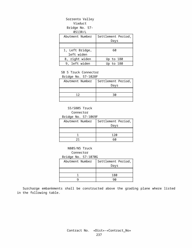
A Production Test Report for all testing performed on each lot shall be prepared by the independent testing laboratory performing the testing and submitted to the QCM for review and approval. The report shall be signed by an engineer who represents the laboratory and is registered as a Civil Engineer in the State of California. The report shall include, as a minimum, the following information for each set: contract number, bridge number, lot number and location, bar size, type of splice, length of mechanical splice, physical condition of test sample splice and control bar, any notable defects, limits of affected zone, total measured slip, location of visible necking area, ultimate strength of each splice, ultimate strength and 95 percent of this ultimate strength for each control bar, and a comparison between 95 percent of the ultimate strength of each control bar and the ultimate strength of its associated splice.
The QCM must review, approve, and forward each Production Test Report to the Engineer for review before any splices represented by the report are encased in concrete. The Engineer shall have 3 working days to review each Production Test Report and respond in writing after a complete report has been received. Should the Contractor elect to encase any splices prior to receiving notification from the Engineer, it is expressly understood that the Contractor will not be relieved of the Contractor's responsibility for incorporating material in the work that conforms to the requirements of the plans and specifications. Any material not conforming to these requirements will be subject to rejection. Should the Contractor elect to wait to encase any splices pending notification by the Engineer, and should the Engineer fail to complete the review and provide notification within this time allowance, and if, in the opinion of the Engineer, the Contractor's controlling operation is delayed or interfered with by reason of the delay in notification, the delay will be considered a right of way delay in conformance with the provisions in Section 8-1.09, "Right of Way Delays," of the Standard Specifications.
Prior to performing any tensile tests on production test sample splices, one of the 4 samples shall be tested for, and shall conform to, the provisions for total slip. Should this sample not meet these requirements, one retest, in which the 3 remaining samples are tested for total slip, will be allowed. Should any of the 3 remaining samples not conform to these requirements, all splices in the lot represented by this production test will be rejected.
If 3 or more sample splices from any production test conform to the provisions in "Ultimate Butt Splice Test Criteria" specified herein, all splices in the lot represented by this production test will be considered acceptable.
Should only 2 sample splices from any production test conform to the provisions in "Ultimate Butt Splice Test Criteria" specified herein, one additional production test shall be performed on the same lot of splices. Should any of the 4 sample splices from this additional test fail to conform to these provisions, all splices in the lot represented by these production tests will be rejected.
If only one sample splice from any production test conforms to the provisions in "Ultimate Butt Splice Test Criteria" specified herein, all splices in the lot represented by this production test will be rejected.
If a production test for any lot fails, the Contractor will be required to repair or replace all reinforcing bars from which sample splices were removed, complete in place, before the Engineer selects any additional splices from this lot for further testing.
Whenever any lot of ultimate butt splices is rejected, additional ultimate butt splices shall not be used in the work until 1) the QCM performs a complete review of the Contractor's quality control process for these splices, 2) a written report is submitted to the Engineer describing the cause of failure for the splices in this lot and provisions for correcting these failures in future lots, and 3) the Engineer has provided the Contractor with written notification that the report is acceptable. The Engineer shall have 3 working days after receipt of the report to provide notification to the Contractor. Should the Engineer not provide notification within this time allowance, and if, in the opinion of the Engineer, the Contractor's controlling operation is delayed or interfered with by reason of this action, the delay will be considered a right of way delay in conformance with the provisions in Section 8-1.09, "Right of Way Delays," of the Standard Specifications.
Production tests will not be required on any repaired splice from a lot, regardless of the type of prequalified ultimate mechanical butt splice used to make the repair.
Should an additional production test be required, the Engineer may select any repaired splice for use in the additional production test.
Quality Assurance Test Requirements for Ultimate Butt SplicesFor the first production test performed, and for at least one, randomly selected by the Engineer, of every 5 additional
production tests, or portion thereof, performed thereafter, the Contractor shall concurrently prepare 4 additional ultimate job control sample splices along with associated control bars. These ultimate job control samples shall be prepared in the same manner as specified herein for ultimate prejob sample splices and control bars.
Each time 4 additional ultimate job control sample splices are prepared, 2 of these job control sample splice and associated control bar sets and 2 of the production sample splice and associated control bar sets, together, shall conform to the requirements for ultimate production sample splices in "Production Test Requirements for Ultimate Butt Splices" specified herein.
The 2 remaining job control sample splice and associated control bar sets, along with the 2 remaining production sample splice and associated control bar sets shall be shipped, unless otherwise directed in writing by the Engineer, to the Transportation Laboratory for quality assurance testing. The 4 sets shall be securely bundled together and identified by
Contract No. «Dist»-«Contract_No»240

location and contract number with weatherproof markings prior to shipment. Bundles containing fewer than 4 sets will not be tested.
Quality assurance testing will be performed in conformance with the requirements for ultimate production sample splices in "Production Test Requirements for Ultimate Butt Splices" specified herein.
Test results for each bundle of 4 sets will be reported in writing to the Contractor within 3 working days after receipt of the bundle by Transportation Laboratory. In the event that more than one bundle is received on the same day, 2 additional working days shall be allowed for providing test results for each additional bundle received. A test report will be made for each bundle received. Should the Contractor elect to encase any splices prior to receiving notification from the Engineer, it is expressly understood that the Contractor will not be relieved of the Contractor's responsibility for incorporating material in the work that conforms to the requirements of the plans and specifications. Any material not conforming to these requirements will be subject to rejection. Should the Contractor elect to wait to encase any splices pending notification by the Engineer, and should the Engineer fail to complete the review and provide notification within this time allowance, and if, in the opinion of the Engineer, the Contractor's controlling operation is delayed or interfered with by reason of the delay in notification, the delay will be considered a right of way delay in conformance with the provisions in Section 8-1.09, "Right of Way Delays," of the Standard Specifications.
EPOXY-COATED PREFABRICATED REINFORCEMENTBar reinforcement to be epoxy-coated shall conform to the ASTM Designation and grade required or permitted by
Section 52-1.02A, "Bar Reinforcement," of the Standard Specifications, for the location or type of structure involved. The coated bar reinforcement shall conform to the requirements in ASTM Designation: A 934/A 934M except as provided herein.
Wire reinforcement to be epoxy-coated shall conform to the ASTM Designation and grade required or permitted by Section 52-1.02D, "Reinforcing Wire and Plain Bars," of the Standard Specifications, for the location or type of structure involved. The coated wire reinforcement shall conform to the requirements for Class A, Type 2 coating of ASTM Designation: A 884/A 884M except as provided herein.
Appendices X1 and X2, "Guidelines For Job-Site Practices," of ASTM Designation: A 884/A 884M and A 934/A 934M, respectively, shall apply except as provided herein. The term "shall" shall replace the term "should" in these appendices. Section X1.2 of Appendix X1 and Section X2.2 of Appendix X2 shall not apply.
All coatings shall be purple or gray in color.Except for field welding of butt splices, all welding of reinforcement shall be complete prior to epoxy coating the
reinforcement.Prior to epoxy coating, all resistance butt welds shall have the weld flash removed to produce a smooth profile free of
any sharp edges that would prevent proper coating of the bar. The flash shall be removed such that the ultimate tensile strength and elongation properties of the bar are not reduced, and the outside radius of the flash, at any point along the circumference of the bar, is 1) not less than the nominal radius of the bar, nor 2) greater than 5 mm beyond the nominal radius of the bar.
A proposed weld flash removal process shall be submitted to and approved by the Engineer in writing, prior to performing any removal work. The submittal shall demonstrate that the proposed flash removal process produces a smooth profile that can be successfully epoxy-coated in conformance with the requirements specified herein.
Bending of epoxy-coated reinforcement after the coating has been applied will not be allowed.When any portion of a reinforcing bar or wire requires epoxy coating, the entire bar or wire shall be coated, except where
shown on the plans and when the bar or wire is spliced outside of the limits of epoxy coating shown on the plans, epoxy coating will not be required on the portion of bar or wire beyond the splice.
Within areas where epoxy-coated reinforcement is required, tie wire and bar chairs or other metallic devices used to secure or support the reinforcement shall be plastic-coated or epoxy-coated to prevent corrosion of the devices or damage to the coated reinforcement.
Prior to coating, the Contractor shall furnish to the Transportation Laboratory a representative 110 g sample from each batch of epoxy coating material to be used. Each sample shall be packaged in an airtight container identified with the manufacturer's name and batch number.
Two 700-mm long samples of coated bar or wire reinforcement from each size and from each load shipped to the jobsite shall be furnished to the Engineer for testing. These samples shall be representative of the material furnished. These samples, as well as any additional random samples taken by the Engineer, may be tested for specification compliance. Additional sampling, and all tests performed by the Engineer, may be performed at any location deemed appropriate by the Engineer. Failure of any sample to meet the requirements of the specifications will be cause for rejection.
If any bar tested for coating thickness or for adhesion of coating fails to meet the requirements for coated bars in Section 9 of ASTM Designation: A 934/A 934M, 2 retests on random samples taken from bars represented by the failed test will be conducted for each failed test. If the results of both retests meet the specified requirements, the coated bars represented by the samples may be certified as meeting the test requirements.
Contract No. «Dist»-«Contract_No»241

If any wire reinforcement tested for coating thickness or for flexibility fails to meet the requirements for coated wire in Section 8 of ASTM Designation: A 884/A 884M, 2 retests on random samples taken from wire represented by the failed test will be conducted for each failed test. If the results of both retests meet the specified requirements, the coated wire represented by the samples may be certified as meeting the test requirements.
Epoxy-coated reinforcement shall be covered with an opaque polyethylene sheeting or other suitable protective material to protect the reinforcement from exposure to sunlight, salt spray, and weather. For stacked bundles, the protective covering shall be draped around the perimeter of the stack. The covering shall be adequately secured; however, it should allow for air circulation around the reinforcement to prevent condensation under the covering. Epoxy-coated reinforcement shall not be stored within 300 m of ocean or tidal water for more than 2 months.
All visible damage to coatings caused by shipping, handling, or installation shall be repaired as required for repairing coating damaged prior to shipment conforming to the requirements in ASTM Designation: A 934/A 934M for bar reinforcement or ASTM Designation: A 884/A 884M for wire reinforcement. When the extent of coating damage prior to repair exceeds 2 percent of the bar or wire surface area in any 300-mm length, repair of the bar or wire will not be allowed, and the coated bar or wire will be rejected.
The patching material and process shall be suitable for field application. The patching material shall be prequalified as required for the coating material and shall be either identified on the container as a material compatible with the reinforcement coating, or shall be accompanied by a Certificate of Compliance certifying that the material is compatible with the reinforcement coating. Damaged areas shall be patched in conformance with the patching material manufacturer's recommendations.
Except for lap splices, all splices for epoxy-coated reinforcement shall be coated with a corrosion protection covering that is on the Department's list of approved products. The covering shall be installed in conformance with the manufacturer's recommendations and as directed by the Engineer. The list is available from the Transportation Laboratory.
A Certificate of Compliance conforming to the provisions in Section 6-1.07, "Certificates of Compliance," of the Standard Specifications, shall be furnished for each shipment of epoxy-coated bar or wire reinforcement certifying that the coated bars or wire conform to the requirements in ASTM Designation: A 934/A 934M for bars or A 884/A 884M for wire and Section 52-1.02B, "Epoxy-coated Reinforcement," of the Standard Specifications. This Certificate of Compliance shall include all the certifications specified in ASTM Designation: A 934/A 934M for bars or ASTM Designation: A 884/A 884M for wire and a statement that the coating material has been prequalified by acceptance testing performed by the Valley Forge Laboratories, Inc., Devon, Pennsylvania.
Any portion of bar or wire reinforcement extending beyond the limits for epoxy-coated reinforcement shown on the plans will be measured and paid for as bar reinforcing steel (bridge).
MEASUREMENT AND PAYMENTMeasurement and payment for reinforcement in structures shall conform to the provisions in Section 52-1.10,
"Measurement," and Section 52-1.11, "Payment," of the Standard Specifications and these special provisions.Full compensation for conforming to the provisions of "Ultimate Butt Splices," of these special provisions shall be
considered as included in the contract prices paid for the various contract items of work involved and no additional compensation will be allowed therefor.
Epoxy-coated bar reinforcement in structures will be measured and paid for as bar reinforcing steel (bridge).
10-1.70 COLUMN CASINGSColumn casings shall consist of cleaned and painted structural steel shells filled with grout as shown on the plans and
conforming to the provisions in Section 55, "Steel Structures," of the Standard Specifications and these special provisions.Attention is directed to "Welding" of these special provisions.For field welding of column casings, only visual inspection will be required, and the requirements of the first sentence of
paragraph 3.13.2 of AWS D1.5 will not apply.Structural steel for column casings shall conform to the requirements in ASTM Designation: A 36/A 36M, or at the
Contractor's option, ASTM Designation: A 709/A 709M, Grade 36.Polyethylene shall have a compressive strength of at least 69 kPa at no more than 15 percent deflection determined in
conformance with the requirements in ASTM Designation: D 3575, Test B. Polyethylene shall be bonded to the column using a suitable waterproof adhesive applied to the entire contact surface.
The spaces to be occupied by the column casing materials shall be cleared of plants and other materials prior to encasing the column.
Removed plants and other materials shall be disposed of outside the highway right of way in conformance with the provisions in Section 7-1.13, "Disposal of Material Outside the Highway Right of Way," of the Standard Specifications.
The same information that is on existing columns shall be painted on casings in conformance with the provisions in Section 51-1.21, "Bridge Name, Number and Bent Numbers," of the Standard Specifications.
Contract No. «Dist»-«Contract_No»242

CLEAN AND PAINT COLUMN CASINGNew metal surfaces, except where galvanized, shall be cleaned and painted in conformance with the provisions in
Sections 59-2, "Painting Structural Steel," and 91, "Paint," of the Standard Specifications and these special provisions.Whenever the Standard Specifications refer to "Steel Structures Painting Council," the reference shall be replaced with
"SSPC: The Society for Protective Coatings."Prior to performing any painting or paint removal, the Contractor shall submit to the Engineer, in conformance with the
provisions in Section 5-1.02, "Plans and Working Drawings," of the Standard Specifications, 3 copies of a separate Painting Quality Work Plan (PQWP) for each item of work for which painting or paint removal is to be performed. As a minimum, each PQWP shall include the following:
A. The name of each Contractor or subcontractor to be used.B. One copy each of all current "SSPC: The Society for Protective Coatings" specifications or qualification procedures
which are applicable to the painting or paint removal to be performed. These documents shall become the permanent property of the Department.
C. Proposed methods and equipment to be used for any paint application.D. Proof of each of any required certifications, SSPC-QP 1 or SSPC-QP 3.
1. In lieu of certification in conformance with the requirements in SSPC-QP 1 for this project, the Contractor may submit written documentation showing conformance with the requirements in Section 3, "General Qualification Requirements," of SSPC-QP 1.
2. In lieu of certification in conformance with the requirements in SSPC-QP 3 for this project, the Contractor may submit written documentation showing conformance with the requirements in Section 3, " General Qualification Requirements," of SSPC-QP 3.
The Contractor shall allow the Engineer 10 working days to review the PQWP submittal after a complete plan has been received. No painting or paint removal shall be performed until the PQWP for that work is reviewed by the Engineer. Should the Engineer fail to complete the review within this time allowance and if, in the opinion of the Engineer, the Contractor's controlling operation is delayed or interfered with by reason of the delay in reviewing the PQWP, the delay will be considered a right of way delay in conformance with the provisions in Section 8-1.09, "Right of Way Delays," of the Standard Specifications.
The Engineer's review of the Contractor's PQWP shall not relieve the Contractor of any responsibility under the contract for the successful completion of the work in conformance with the requirements of the plans and specifications. The Engineer's review shall not constitute a waiver of any of the requirements of the plans and specifications nor relieve the Contractor of any obligation thereunder, and defective work, materials, and equipment may be rejected notwithstanding review of the PQWP.
The existing paint systems consist of materials listed in "Existing Highway Facilities" of these special provisions.Column casing surfaces in contact with grout shall not be considered embedded in concrete.Where flame sprayed plastic is shown on the plans, the exposed exterior surfaces and exterior surfaces below ground or
water shall be cleaned and painted with a coat of flame sprayed plastic, and the remaining new metal surfaces shall be cleaned and painted with waterborne inorganic zinc coating. The waterborne inorganic zinc coating will not be required under flame sprayed plastic.
A qualified representative of the manufacturer of the flame sprayed plastic shall be present during the first 3 days of flame sprayed plastic application and shall be available for advice during the remaining time of flame sprayed plastic application.
Blast cleaning or application of flame sprayed plastic shall conform to the provisions for blast cleaning or application of solvent-borne paint in Section 59-1.02, "Weather Conditions," of the Standard Specifications, except the maximum surface temperature restrictions shall be in conformance with these special provisions.
Column casing surfaces to be painted with flame sprayed plastic shall be blast cleaned and painted with the flame sprayed plastic at the jobsite.
Column casing surfaces to be painted with waterborne inorganic zinc coating shall be blast cleaned and painted with the single undercoat prior to shipment to the job-site.
CleaningThe surfaces to be cleaned and painted shall be dry blast cleaned in conformance with the requirements of Surface
Preparation Specification No. 10, "Near White Blast Cleaning," of the "SSPC: The Society for Protective Coatings." For surfaces coated with waterborne inorganic zinc coating, blast cleaning shall leave a dense, uniform, angular anchor pattern of no less than 40 µm nor more than 86 µm as measured in conformance with the requirements in ASTM Designation: D 4417,
Contract No. «Dist»-«Contract_No»243
and for surfaces to be coated with flame sprayed plastic, blast cleaning shall leave a dense, uniform, angular anchor pattern of between 50 µm and 75 µm.
Mineral and slag abrasives used for blast cleaning steel shall conform to the requirements of Abrasive Specification No. 1, "Mineral and Slag Abrasives," of the "SSPC: The Society for Protective Coatings," and shall not contain hazardous material. Mineral and slag abrasives shall comply with the requirements for Class A, Grade 2 to 3 as defined therein.
A Certificate of Compliance conforming to the provisions in Section 6-1.07, "Certificates of Compliance," of the Standard Specifications and a Material Safety Data Sheet shall be furnished prior to use for each shipment of blast cleaning material for steel.
PaintingExcept for surfaces to be coated with flame sprayed plastic, all blast cleaned surfaces shall receive a single undercoat of
waterborne inorganic zinc coating, and exposed surfaces shall receive a single undercoat and a final coat. The single undercoat and final coat shall consist of a waterborne inorganic zinc coating conforming to the requirements in AASHTO Designation M 300, Type II, except that: 1) the first 3 sentences of Section 4.7, "Primer Field Performance Requirements," and the entire Section 4.7.1 shall not apply, and 2) zinc dust shall be Type II in conformance with the requirements in ASTM Designation: D 520. The inorganic zinc coating shall be listed on the qualified products list which may be obtained from the Transportation Laboratory.
The color of the final coat of inorganic zinc coating shall match Federal Standard 595B No. 36373.Inorganic zinc coating shall be used within 12 hours of initial mixing.Application of inorganic zinc coating shall conform to the provisions for applying zinc-rich coating in Section 59-2.13,
"Application of Zinc-Rich Primer," of the Standard Specifications.Inorganic zinc coating shall not be applied when the atmospheric or surface temperature is less than 7°C or more than
29°C, nor when the relative humidity exceeds 85 percent.The single undercoat of inorganic zinc coating shall be applied to the required dry film thickness in 2 or more
applications within 4 hours after blast cleaning.The total dry film thickness of all applications of the single undercoat of inorganic zinc coating shall be not less than
100 µm nor more than 200 µm.Damaged areas and areas where mudcracking occurs in the inorganic zinc coating shall be blast cleaned and repainted
with inorganic zinc coating to the specified thickness.Dry spray, or overspray, as defined in the Steel Structures Painting Manual, Volume 1, "Good Painting Practice," of the
"SSPC: The Society for Protective Coatings," shall be removed prior to application of subsequent coats or final acceptance. Removal of dry spray shall be by screening or other methods that minimize polishing of the inorganic zinc surface. The dry film thickness of the coating after removal of dry spray shall be in conformance with the provisions for applying the single undercoat, as specified herein.
The inorganic zinc coating shall be tested for adhesion and cure. The locations of the tests will be determined by the Engineer. The sequence of the rinsing and testing operations shall be determined by the Contractor. The testing for adhesion and cure will be performed no sooner than 72 hours after application of the single undercoat of inorganic zinc coating. At the Contractor's expense, satisfactory access shall be provided to allow the Engineer to determine the location of the tests and to test the inorganic zinc coating cure. The inorganic zinc coating shall pass the following tests:
AdhesionThe inorganic zinc coating shall have a minimum adhesion to steel of 4 MPa when measured at no more than 6 locations
on each column using a self-aligning adhesion tester in conformance with the requirements in ASTM Designation: D 4541. The Contractor, at the Contractor's expense, shall: (1) verify compliance with the adhesion requirements, (2) furnish test results to the Engineer, and (3) repair the coating after testing.
CureThe inorganic zinc coating, when properly cured, shall exhibit a solid, hard, and polished metal surface when firmly
scraped with the knurled edge of a quarter. Inorganic zinc coating that is powdery, soft, or does not exhibit a polished metal surface, as determined by the Engineer, shall be repaired by the Contractor, at the Contractor's expense, by blast cleaning and repainting with inorganic zinc coating to the specified thickness.
Except as approved by the Engineer, a minimum curing time of 72 hours shall be allowed between application of inorganic zinc coating and water rinsing.
Exposed areas of inorganic zinc coating where finish coats are specified shall be thoroughly water rinsed.
Contract No. «Dist»-«Contract_No»244

The final coat of inorganic zinc coating shall be applied after testing for adhesion, testing for cure, and completion of all operations that may damage or discolor the steel surface, including correction of runs, sags, thin and excessively thick areas in the paint film, skips and holidays, dry spray, or areas of non-uniform appearance.
The area to receive the final coat of inorganic zinc coating shall be lightly roughened by abrasive blasting using an abrasive no larger than 600 µm mesh. Abrasive blasting shall remove no more than 15 µm of inorganic zinc. The surface to be lightly roughened shall be free from moisture, dust, grease or any deleterious material. The undercoated areas of column casing surfaces not receiving a final coat shall be protected from abrasive blast cleaning operations.
The final coat of inorganic zinc coating shall be applied to the required dry film thickness in one uniform application within 24 hours after light roughening. The dry film thickness of the final coat of inorganic zinc coating shall be not less than 25 µm nor more than 75 µm.
The total dry film thickness of all applications of the single undercoat and final coat of inorganic zinc coating shall be not less than 125 µm nor more than 275 µm.
Finish coats will not be required.Flame sprayed plastic shall be applied within 8 hours after blast cleaning. The entire thickness of the flame sprayed
plastic shall be applied in one continuous operation. Any seams in the flame sprayed plastic shall be horizontal and fused completely together.
Contract No. «Dist»-«Contract_No»245

Surfaces to be coated with flame sprayed plastic shall receive a flame sprayed plastic which consists of thermoplastic powder, pigments, and other additives which are melt blended by the manufacturer specifically for application through a propane gas flame.
The thermoplastic powder shall be an ethylene methacrylic acid copolymer (EMA), or at the Contractor's option, ethylene acrylic acid copolymer (EAA) and shall have the following properties:
Property EMA Requirement EAA Requirement ASTM Designation
Melt Index, at 190°C and 2.16 Kg load, g/10 minutes
32 ± 3 20 ± 3 D 1238
Density, g/cm3 0.930 to 0.940 0.940 to 0.970 D 792Hardness, Shore D 48 ± 2 54 ± 2 D 2240
The color of flame sprayed plastic shall closely match Federal Standard 595B No. 26408.Prior to application of flame sprayed plastic, the Contractor shall furnish to the Transportation Laboratory a
representative one pound sample from each batch of pre-blended flame sprayed plastic material. Each sample shall be packaged in an air tight container identified with the manufacturer's name and the manufacturer's batch number.
Flame spray equipment shall be operated in conformance with the manufacturer's instructions.Surfaces to receive flame sprayed plastic shall be preheated to between 77°C and 88°C immediately prior to coating.
The Contractor, at his expense, shall verify the surface temperature using an infrared thermometer.The minimum thickness of flame sprayed plastic shall be 375 µm.The coating of flame sprayed plastic shall be free of pinholes when tested with a low voltage, 67.5 volts, wet sponge
holiday detector. The coating of flame sprayed plastic shall have a minimum adhesion to steel of 7 MPa when measured at no more than 4 locations on each column in conformance with the requirements in ASTM Designation: D 4541. The locations of pinhole and adhesion tests will be determined by the Engineer. The Contractor at his expense shall: (1) verify compliance with the pinhole and adhesion requirements, (2) furnish test results to the Engineer, and (3) repair the coating after testing.
GROUTINGGrouting shall conform to the provisions in Section 50-1.09, "Bonding and Grouting," of the Standard Specifications and
these special provisions.For non-circular columns where the minimum gap to be filled with grout is 25 mm and the maximum gap is greater than
100 mm, aggregate shall be used to extend the grout, but only to the extent that the cement content of the grout is not less than 500 kilograms per cubic meter of grout. California Test 541 will not be required nor will the grout be required to pass through a sieve with a 1.8-mm maximum clear opening prior to being introduced into the grout pump. Aggregate shall consist of at least 70 percent fine aggregate and approximately 30 percent pea gravel, by weight. Fine aggregate shall conform to the provisions of Section 90-2, "Materials," of the Standard Specifications. The size of pea gravel shall be such that 100 percent passes the 12.5-mm sieve, a minimum 90 percent passes the 9.5-mm sieve and not more than 5 percent passes the 2.36-mm sieve.
The Contractor shall limit the height of each lift of grout to minimize undulations and displacements of the surface of the shell during grouting. Undulations in the shell surface, including undulations from fabrication and erection, shall not exceed 6 mm in 300 mm nor shall the total displacement from plan location exceed 50 mm at any point. At the Contractor's option, a bracing system or other means may be employed to restrain the casing within the specified tolerances. Except where shown on the plans, restraints shall not pass through the columns. The grout shall harden prior to placing the next lift of grout, unless a bracing system is used.
In addition to the above grout lift restrictions, the height of grout lifts for portions of column casings containing polyethylene shall not exceed 3 m.
Suitable external grout injection valves shall be installed for filling of the casings. The filling operation shall begin at the bottom of the casing. Spacing of the valves shall be such that the grout will fill the gap between the casing and the polyethylene or column.
Casings shall be sealed at the bottom. Grout shall be pumped into the casing such that the grout head is maintained uniformly around the column, and no visible evidence of water or air is ejected at the top of the grout. The grout at the casing top shall be covered with mortar and sloped to drain. Mortar shall conform to the provisions in Section 51-1.135, "Mortar," of the Standard Specifications.
Casings shall be positioned with spacers to center the casing around the existing column at the location shown on the plans. Spacers may be welded to the inside of the casing. Spacers shall not be used in areas occupied by the polyethylene.
Contract No. «Dist»-«Contract_No»246

Grout shall not be permitted to flow across shoulders or lanes occupied by public traffic, or to flow into gutters or other drainage facilities.
Clamps, valves, injection ports, lifting ears and other accessories shall be completely removed not less than 24-hours after placing grout. Voids shall be filled with mortar and finished flush with the exterior surface of the casing, except that where flame sprayed plastic is shown on the plans, voids shall be covered flush with the exterior surface of the casing with caps, plugs or welded plates.
MEASUREMENT AND PAYMENTColumn casings will be measured and paid for in conformance with the provisions in Section 55-4.01, "Measurement,"
of the Standard Specifications and these special provisions.The contract price paid per kilogram for column casing shall include full compensation for furnishing all labor, materials
(including polyethylene and adhesive), tools, equipment, and incidentals, and for doing all the work involved in column casings filled with grout, complete in place, including cleaning and painting of structural steel, as shown on the plans, as specified in the Standard Specifications and these special provisions, and as directed by the Engineer.
Full compensation for furnishing of and coating with flame sprayed plastic shall be considered as included in the contract price paid per kilogram for column casing and no additional compensation will be allowed therefor.
10-1.71 ISOLATION CASINGSIsolation casings shall consist of galvanized structural steel plate pipe with steel angles and neoprene strip as shown on
the plans and conforming to the provisions in Section 55, "Steel Structures," of the Standard Specifications and these special provisions.
Concrete and drilling and bonding dowels, epoxy cartridge shall conform to the provisions in “Concrete Structures” of these special provisions.
Structural steel for isolation casings shall conform to the requirements in ASTM Designation: A 36/A 36M, or at the Contractor's option, ASTM Designation: A 709/A 709M, Grade 36.
New metal surfaces shall be galvanized.
MEASUREMENT AND PAYMENTIsolation casings will be measured and paid for in conformance with the provisions in Section 55-4.01, "Measurement,"
of the Standard Specifications and these special provisions.The contract price paid per kilogram for isolation casing shall include full compensation for furnishing all labor,
materials, tools, equipment, and incidentals, and for doing all the work involved in isolation casings, complete in place, including steel angles, neoprene strip, drill and bond dowels, epoxy cartridge and resin capsules, as shown on the plans, as specified in the Standard Specifications and these special provisions, and as directed by the Engineer.
10-1.72 SIGN STRUCTURESSign structures and foundations for overhead signs shall conform to the provisions in Section 56-1, "Overhead Sign
Structures," of the Standard Specifications and these special provisions.Before commencing fabrication of sign structures, the Contractor shall submit 2 sets of working drawings to the
Engineer in conformance with the provisions in Section 5-1.02, "Plans and Working Drawings," of the Standard Specifications. The working drawings shall include sign panel dimensions, span lengths, post heights, anchorage layouts, proposed splice locations, a snugging and tensioning pattern for anchor bolts and high strength bolted connections, and details for permanent steel anchor bolt templates. The working drawings shall be supplemented with a written quality control program that includes methods, equipment, and personnel necessary to satisfy the requirements specified herein and in the special provisions.
Working drawings shall be 559 mm x 864 mm or 279 mm x 432 mm in size and each drawing and calculation sheet shall include the State assigned designations for the contract number, sign structure type and reference as shown on the contract plans, District-County-Route-Kilometer Post, and contract number.
The Engineer shall have 20 working days to review the sign structure working drawings after a complete submittal has been received. No fabrication or installation of sign structures shall be performed until the working drawings are approved in writing by the Engineer.
Should the Engineer fail to complete the review within the time allowance and if, in the opinion of the Engineer, the Contractor's controlling operation is delayed or interfered with by reason of the delay in reviewing the sign structure working drawings, the delay will be considered a right of way delay in conformance with the provisions in Section 8-1.09, "Right of Way Delays," of the Standard Specifications.
The third paragraph of Section 56-1.01, "Description," of the Standard Specifications shall not apply.A permanent steel template shall be used to maintain the proper anchor bolt spacing.
Contract No. «Dist»-«Contract_No»247

One top nut, one leveling nut, and 2 washers shall be provided for the upper threaded portion of each anchor bolt.Surfaces of base plates which are to come in contact with concrete, grout, or washers and leveling nuts shall be flat to
within 3 mm tolerance in 305 mm, and to within 5 mm tolerance overall. Faying surfaces of plates in high-strength bolted connections including flange surfaces of field splices, chord joints, and frame junctures, and contact surfaces of plates used for breakaway slip base assemblies shall be flat to within 2 mm tolerance in 305 mm, and within 3 mm tolerance overall.
Thermally cut holes made in tubular members of sign supports, other than holes in base and flange plates, shall initially be made a minimum of 2 mm undersized, and then be mechanically enlarged by reaming or grinding to the final required size and shape. All edges shall have a surface roughness of not greater than 6.35 m. Round holes may be drilled to the exact final diameter. No holes shall be made in members unless the holes are shown on the plans or are approved in writing by the Engineer.
The sixth through the thirteenth paragraphs in Section 56-1.03, "Fabrication," of the Standard Specifications are amended to read:
High-strength bolted connections, where shown on the plans, shall conform to the provisions in Section 55-3.14, "Bolted Connections," except that only fastener assemblies consisting of a high-strength bolt, nut, hardened washer, and direct tension indicator shall be used.
High-strength fastener assemblies, and any other bolts, nuts, and washers attached to sign structures shall be zinc-coated by the mechanical deposition process.
An alternating snugging and tensioning pattern for anchor bolts and high-strength bolted splices shall be used. Once tensioned, high-strength fastener components and direct tension indicators shall not be reused.
For bolt diameters less than 10 mm, the diameter of the bolt hole shall be not more than 0.80-mm larger than the nominal bolt diameter. For bolt diameters greater than or equal to 10 mm, the diameter of the bolt hole shall be not more than 1.6 mm larger than the nominal bolt diameter.
Sign structures shall be fabricated into the largest practical sections prior to galvanizing. Ribbed sheet metal panels for box beam closed truss sign structures shall be fastened to the truss members by cap
screws or bolts as shown on the plans, or by 4.76 mm stainless steel blind rivets conforming to Industrial Fasteners Institute, Standard IFI-114, Grade 51. The outside diameter of the large flange rivet head shall be not less than 15.88 mm in diameter. Web splices in ribbed sheet metal panels may be made with similar type blind rivets of a size suitable for the thickness of material being connected.
Spalling or chipping of concrete structures shall be repaired by the Contractor at the Contractor's expense. Overhead sign supports shall have an aluminum identification plate permanently attached near the base, adjacent to
the traffic side on one of the vertical posts, using either stainless steel rivets or stainless steel screws. As a minimum, the information on the plate shall include the name of the manufacturer, the date of manufacture and the contract number.
Steel members used for overhead sign structures shall receive nondestructive testing (NDT) in conformance with AWS D1.1 and the following:
A.Weld Location Weld Type Minimum
Required NDT Welds for butt joint welds in tubular sections, nontubular sections, and posts
CJP groove weld with backing ring
100% UT or RT
Longitudinal seam welds* PJP groove weld 25% MTCJP groove weld 100% UT or RT
Welds for base plate, flange plate, or end cap to post or mast arm
CJP groove weld 25% UT or RT
Fillet weld 25% MT* Longitudinal seam welds shall have 60% minimum penetration, except that within 150 mm of any circumferential weld, longitudinal seam welds shall be CJP groove welds.
B. A written procedure approved by the engineer shall be used when performing UT on material less than 8 mm thick. Contoured shoes shall be used when performing UT on round tubular sections under 1270 mm in diameter.
C. When less than 100 percent of a weld is specified for NDT, and if defects are found during this inspection, additional NDT shall be performed. This additional NDT shall be performed on 25 percent of the total weld for all similar welds, as determined by the Engineer, produced for sign structures in the project. If any portion of the additional weld inspected is found defective, 100 percent of all similar welds produced for sign structures in the project, as determined by the Engineer, shall be tested.
Contract No. «Dist»-«Contract_No»248

Circumferential welds and base plate to post welds may be repaired only one time without written permission from the Engineer.
All ferrous metal parts of tubular sign structures shall be galvanized and shall not be painted.Full compensation for furnishing anchor bolt templates and for testing of welds shall be considered as included in the
contract price paid per kilogram for furnish sign structure and no additional compensation will be allowed therefor.
10-1.73 ROADSIDE SIGNSRoadside signs shall be installed at the locations shown on the plans or where designated by the Engineer and in
conformance with the provisions in Section 56-2, "Roadside Signs," of the Standard Specifications and these special provisions.
Wood posts shall be pressure treated after fabrication in conformance with the provisions in Section 58, "Preservative Treatment of Lumber, Timber and Piling," of the Standard Specifications with creosote, creosote coal tar solution, creosote petroleum solution (50-50), pentachlorophenol in hydrocarbon solvent, copper naphthenate, ammoniacal copper arsenate, or ammoniacal copper zinc arsenate. In addition to the preservatives listed above, Southern yellow pine may also be pressure treated with chromated copper arsenate. When other than one of the creosote processes is used, blocks shall have a minimum retention of 6.4 kg/m3, and need not be incised.
10-1.74 CLEAN AND PAINT STRUCTURAL STEELExposed new metal surfaces, except where galvanized, shall be cleaned and painted in conformance with the provisions
in Section 59-2, "Painting Structural Steel," and Section 91, "Paint," of the Standard Specifications and these special provisions.
Whenever the Standard Specifications refer to "Steel Structures Painting Council," the reference shall be replaced with "SSPC: The Society for Protective Coatings."
Section 59-2.01, "General," of the Standard Specifications is amended by adding the following paragraphs after the first paragraph:
• Unless otherwise specified, no painting Contractors or subcontractors will be permitted to commence work without having the following current "SSPC: The Society for Protective Coatings" (formerly the Steel Structures Painting Council) certifications in good standing:
A. For cleaning and painting structural steel in the field, certification in conformance with the requirements in Qualification Procedure No. 1, "Standard Procedure For Evaluating Painting Contractors (Field Application to Complex Industrial Structures)" (SSPC-QP 1).
B. For removing paint from structural steel, certification in conformance with the requirements in Qualification Procedure No. 2, "Standard Procedure For Evaluating Painting Contractors (Field Removal of Hazardous Coatings from Complex Structures)" (SSPC-QP 2).
C. For cleaning and painting structural steel in a permanent painting facility, certification in conformance with the requirements in Qualification Procedure No. 3, "Standard Procedure For Evaluating Qualifications of Shop Painting Applicators" (SSPC-QP 3). The AISC's Sophisticated Paint Endorsement (SPE) quality program will be considered equivalent to SSPC-QP 3.
Prior to performing any painting or paint removal, the Contractor shall submit to the Engineer, in conformance with the provisions in Section 5-1.02, "Plans and Working Drawings," of the Standard Specifications, 3 copies of a separate Painting Quality Work Plan (PQWP) for each item of work for which painting or paint removal is to be performed. As a minimum, each PQWP shall include the following:
A. The name of each Contractor or subcontractor to be used.B. One copy each of all current "SSPC: The Society for Protective Coatings" specifications or qualification procedures
which are applicable to the painting or paint removal to be performed. These documents shall become the permanent property of the Department.
C. Proposed methods and equipment to be used for any paint application.D. Proof of each of any required certifications, SSPC-QP 1, SSPC-QP 2, SSPC-QP 3.
1. In lieu of certification in conformance with the requirements in SSPC-QP 1 for this project, the Contractor may submit written documentation showing conformance with the requirements in Section 3, "General Qualification Requirements," of SSPC-QP 1.
Contract No. «Dist»-«Contract_No»249

2. In lieu of certification in conformance with the requirements in SSPC-QP 2 for this project, the Contractor may submit written documentation showing conformance with the requirements in Sections 4.2 through 4.6 of SSPC-QP 2.
3. In lieu of certification in conformance with the requirements in SSPC-QP 3 for this project, the Contractor may submit written documentation showing conformance with the requirements in Section 3, " General Qualification Requirements," of SSPC-QP 3.
The Engineer shall have 10 working days to review the PQWP submittal after a complete plan has been received. No painting or paint removal shall be performed until the PQWP for that work is reviewed by the Engineer. Should the Engineer fail to complete the review within this time allowance and if, in the opinion of the Engineer, the Contractor's controlling operation is delayed or interfered with by reason of the delay in reviewing the PQWP, the delay will be considered a right of way delay in conformance with the provisions in Section 8-1.09, "Right of Way Delays," of the Standard Specifications.
It is expressly understood that the Engineer's review of the Contractor's PQWP shall not relieve the Contractor of any responsibility under the contract for the successful completion of the work in conformity with the requirements of the plans and specifications. The Engineer's review shall not constitute a waiver of any of the requirements of the plans and specifications nor relieve the Contractor of any obligation thereunder, and defective work, materials, and equipment may be rejected notwithstanding review of the PQWP.
CLEANINGExposed new metal surfaces shall be dry blast cleaned in conformance with the requirements in Surface Preparation
Specification No. 10, "Near White Blast Cleaning," of the "SSPC: The Society for Protective Coatings." Blast cleaning shall leave surfaces with a dense, uniform, angular anchor pattern of not less than 40 µm nor more than 86 µm as measured in conformance with the requirements in ASTM Designation: D 4417.
Mineral and slag abrasives used for blast cleaning steel shall conform to the requirements in Abrasive Specification No. 1, "Mineral and Slag Abrasives," of the "SSPC: The Society for Protective Coatings" and shall not contain hazardous material. Mineral and slag abrasives shall comply with the requirements for Class A, Grade 2 to 3 as defined therein.
A Certificate of Compliance conforming to the provisions in Section 6-1.07, "Certificates of Compliance," of the Standard Specifications and a Material Safety Data Sheet shall be furnished prior to use for each shipment of blast cleaning material for steel.
PAINTINGBlast cleaned surfaces shall receive a single undercoat, and a final coat where specified, consisting of a waterborne
inorganic zinc coating conforming to the requirements in AASHTO Designation M 300, Type II, except that: 1) the first 3 sentences of Section 4.7, "Primer Field Performance Requirements," and the entire Section 4.7.1 shall not apply, and 2) zinc dust shall be Type II in conformance with the requirements in ASTM Designation: D 520. The inorganic zinc coating shall be listed on the qualified products list which may be obtained from the Transportation Laboratory.
The color of the final application of inorganic zinc coating shall match Federal Standard 595B No. 36373.Inorganic zinc coating shall be used within 12 hours of initial mixing.Application of inorganic zinc coating shall conform to the provisions for applying zinc-rich coating in Section 59-2.13,
"Application of Zinc-Rich Primer," of the Standard Specifications.Inorganic zinc coating shall not be applied when the atmospheric or surface temperature is less than 7°C or more than
29°C, nor when the relative humidity exceeds 85 percent.The single undercoat of inorganic zinc coating shall be applied to the required dry film thickness in 2 or more
applications within 4 hours after blast cleaning.The total dry film thickness of all applications of the inorganic zinc undercoat, including the surfaces of outside existing
members within the grip under bolt heads, nuts and washers, shall be not less than 100 µm nor more than 200 µm, except that the total dry film thickness on each faying (contact) surface of high strength bolted connections shall be between 25 µm and the maximum allowable dry film thickness for Class B coatings as determined by certified testing in conformance with Appendix A of the "Specification for Structural Joints Using ASTM A325 or A490 Bolts" of the Research Council on Structural Connections (RCSC Specification). Unless otherwise stated, all inorganic zinc coatings used on faying surfaces shall meet the slip coefficient requirements for a Class B coating on blast-cleaned steel, as specified in the RCSC Specification. The Contractor shall provide results of certified testing showing the maximum allowable dry film thickness for the Class B coating from the qualifying tests for the coating he has chosen, and shall maintain the coating thickness on actual faying surfaces of the structure at or below this maximum allowable coating thickness.
Areas where mudcracking occurs in the inorganic zinc coating shall be blast cleaned and repainted with inorganic zinc coating to the specified thickness.
Dry spray, or overspray, as defined in the Steel Structures Painting Manual, Volume 1, "Good Painting Practice," of the "SSPC: The Society for Protective Coatings," shall be removed prior to application of subsequent coats or final acceptance.
Contract No. «Dist»-«Contract_No»250

Removal of dry spray shall be by screening or other methods that minimize polishing of the inorganic zinc surface. The dry film thickness of the coating after removal of dry spray shall be in conformance with the provisions for applying the single undercoat, as specified herein.
The inorganic zinc coating shall be tested for adhesion and cure. The locations of the tests will be determined by the Engineer. The sequence of the testing operations shall be determined by the Contractor. The testing for adhesion and cure will be performed no sooner than 72 hours after application of the single undercoat of inorganic zinc coating. At the Contractor's expense, satisfactory access shall be provided to allow the Engineer to determine the location of the tests and to test the inorganic zinc coating cure. The inorganic zinc coating shall pass the following tests:
AdhesionThe inorganic zinc coating shall have a minimum adhesion to steel of 4 MPa when measured at no more than 6 locations
per span on each girder using a self-aligning adhesion tester in conformance with the requirements in ASTM Designation: D 4541. The Contractor, at the Contractor's expense, shall: (1) verify compliance with the adhesion requirements, (2) furnish test results to the Engineer, and (3) repair the coating after testing.
CureThe inorganic zinc coating, when properly cured, shall exhibit a solid, hard, and polished metal surface when firmly
scraped with the knurled edge of a quarter. Inorganic zinc coating that is powdery, soft, or does not exhibit a polished metal surface, as determined by the Engineer, shall be repaired by the Contractor, at the Contractor's expense, by blast cleaning and repainting with inorganic zinc coating to the specified thickness.
The final coat of inorganic zinc coating shall be applied after testing for adhesion, testing for cure, and completion of all operations that may damage or discolor the steel surface, including correction of runs, sags, thin and excessively thick areas in the paint film, skips and holidays, dry spray, or areas of non-uniform appearance.
The area to receive the final coat of inorganic zinc coating shall be lightly roughened by abrasive blasting using an abrasive no larger than 600 µm. Abrasive blasting shall remove no more than 15 µm of inorganic zinc. The surface to be lightly roughened shall be free from moisture, dust, grease or deleterious material. The undercoated areas of the under surfaces of bottom flanges shall be protected from abrasive blast cleaning operations.
The final coat of inorganic zinc coating shall be applied to the required dry film thickness in one uniform application within 24 hours after light roughening. The dry film thickness of the final coat shall be not less than 25 µm nor more than 75 µm.
Except at bolted connections, the total dry film thickness of all applications of the single undercoat and final coat of inorganic zinc coating shall be not less than 125 µm nor more than 275 µm.
Finish coats will not be required.
10-1.75 PREPARE AND STAIN CONCRETEThis work shall consist of preparing and staining concrete surfaces where shown on the plans to be stained or which are
designated to be stained in these special provisions.After completion of the class of concrete surface finish required in Section 51, "Concrete Structures," of the Standard
Specifications, the surfaces of the concrete to be stained shall be prepared by a light water blasting of the surface as necessary to remove any remaining form oil or other contaminants. The concrete surface shall be thoroughly dry at the time stain is applied.
The stain shall be of a water based, styrene-acrylic coating which has been commercially manufactured for use as an exterior concrete stain. The stain shall be formulated and applied so that the color of the stained concrete closely conforms to the Sample Panel No. 3 described under "Architectural Surface (Textured Concrete)" elsewhere in these special provisions.
Each coat shall be thoroughly cured before the succeeding coat is applied. Areas not to be stained shall be protected so that they remain stain-free.
Preparing and staining concrete will be measured by the square meter. Measurement will be made along the surface of the actual areas stained.
The contract price paid per square meter for prepare and stain concrete shall include full compensation for furnishing all labor, materials, tools, equipment, and incidentals, and for doing all work involved in preparing surfaces and applying stain to concrete surfaces, as shown on the plans, as specified in these specifications, and as directed by the Engineer.
10-1.76 ALTERNATIVE PIPEAlternative pipe culverts shall conform to the provisions in Section 62, "Alternative Culverts," of the Standard
Specifications and these special provisions.
Contract No. «Dist»-«Contract_No»251

Slurry cement backfill, where shown on the plans, shall conform to Section 19-3.062, "Slurry Cement Backfill," of the Standard Specifications.
REINFORCED CONCRETE PIPEReinforced concrete pipe shall conform to the provisions in "Reinforced Concrete Pipe," elsewhere in these special
provisions.
PLASTIC PIPEPlastic pipe shall conform to the provisions in "Plastic Pipe," elsewhere in these special provisions.
10-1.77 PLASTIC PIPEPlastic pipe shall conform to the provisions in Section 64, "Plastic Pipe," of the Standard Specifications and these special
provisions.Drainage unit 76 (e) shall be High Density Polyethylene plastic pipe, Type S.The pipe shall be grouted as recommended by the manufacturer.Grout will be measured and paid for by the cubic meter.The contract price paid per cubic meter for high density polyethylene pipe lining grout shall include full compensation
for furnishing all labor, materials, tools, equipment, and incidentals, and for doing all the work involved in grouting the pipe, complete in place, as shown on the plans, as specified in the Standard Specifications and these special provisions, and as directed by the Engineer.
10-1.78 REINFORCED CONCRETE PIPEReinforced concrete pipe shall conform to the provisions in Section 65, "Reinforced Concrete Pipe," of the Standard
Specifications and these special provisions.Where embankment will not be placed over the top of the pipe, a relative compaction of not less than 85 percent shall be
required below the pipe spring line for pipe installed using Method 1 backfill in trench, as shown on Standard Plan A62D. Where the pipe is to be placed under the traveled way, a relative compaction of not less than 90 percent shall be required unless the minimum distance between the top of the pipe and the pavement surface is the greater of 1.2 m or one half of the outside diameter of the pipe.
Except as otherwise designated by classification on the plans or in the specifications, joints for culvert and drainage pipes shall conform to the plans or specifications for standard joints.
When reinforced concrete pipe is installed in conformance with the details shown on Revised Standard Plan A62DA, the fifth paragraph of Section 19-3.04, "Water Control and Foundation Treatment," of the Standard Specifications shall not apply.
When solid rock or other unyielding material is encountered at the planned elevation of the bottom of the bedding, the material below the bottom of the bedding shall be removed to a depth of 1/50 of the height of the embankment over the top of the culvert, but not less than 150 mm nor more than 300 mm. The resulting trench below the bottom of the bedding shall be backfilled with structure backfill material in conformance with the provisions in Section 19-3.06, "Structure Backfill," of the Standard Specifications.
The excavation and backfill below the planned elevation of the bottom of the bedding will be paid for as extra work as provided in Section 4-1.03D, "Extra Work," of the Standard Specifications.
The Outer Bedding shown on Revised Standard Plan A62DA shall not be compacted prior to placement of the pipe.
10-1.79 STRUCTURAL STEEL PLATE PIPEStructural steel plate pipe and structural steel plate pipe arch shall conform to the provisions in Section 67, "Structural
Metal Plate Pipe," of the Standard Specifications.
10-1.80 OVERSIDE DRAINSteel pipe downdrains shall conform to the provisions in Section 66, "Corrugated Metal Pipe," of the Standard
Specifications and these special provisions.Steel pipe downdrains shall be fabricated from zinc-coated steel sheet.Universal coupling bands constructed with dimples, as shown on the Standard Plans, shall not be used in the work,
except as otherwise provided herein.When any corrugated steel pipe has been cut in the field, the connections shall be made with a coupling band and a
portland cement concrete collar. The coupling band shall be the universal type constructed with dimples or the helical type. The concrete collar shall encase each pipe as shown on the plans. Collars for pipe 600 millimeter and larger in diameter shall be reinforced in accordance with the details shown on the plans for a Type 2 collar.
Contract No. «Dist»-«Contract_No»252

Downdrains will be measured and paid for in the same manner as corrugated steel pipe.
10-1.81 MISCELLANEOUS FACILITIESCorrugated steel pipe risers, reinforced concrete pipe risers, and precast concrete pipe risers shall conform to the
provisions in Section 70, "Miscellaneous Facilities," of the Standard Specifications and these special provisions.Attention is directed to "Reinforced Concrete Pipe" of these special provisions.
10-1.82 GRATED LINE DRAINThis work shall consist of furnishing and installing precast grated line drain, with necessary fittings, coupling systems,
frames, grates and associated items as shown on the plans and in conformance with these special provisions.The interior surface of the grated line drain, below the level of the frame and grate and associated connections, shall be
smooth. Grated line drain channel sections shall be manufactured of monolithic polymer concrete with no side extensions. Monolithic polymer concrete shall be made from a composition of aggregate and polyester resin or vinylester resin and
shall have the following properties when tested as follows:
PROPERTY ASTMTEST METHOD
VALUE
Tensile Strength, MPa C 307 10 min.Compressive Strength, MPa C 579 80 min.Bending Strength, MPa C 580 20 min.Moisture Absorption, % C 140 0.5 max.Chemical Resistance C 267 PassFreeze/Thaw, number of cycles w/o weight loss C 666 1600 min.
The manufacturer of the grated line drain shall furnish the Engineer a Certificate of Compliance in conformance with the provisions in Section 6-1.07, "Certificates of Compliance," of the Standard Specifications.
Grated line drain frames and grates shall be manufactured of ductile iron conforming to the provisions in Section 75-1.02, "Miscellaneous Iron and Steel," of the Standard Specifications. The frames and grates need not be galvanized or coated with asphalt paint. Bolts, nuts, frame anchors, and other connecting hardware shall conform to the provisions in Section 75-1.02, "Miscellaneous Iron and Steel," of the Standard Specifications.
Frames and grates, when installed in conformance with the manufacturer's recommendations and these special provisions, shall withstand load testing conforming to the requirements in Federal Specification RR-F-621E for "Frames, Covers, Gratings, Steps, Manhole Sump and Catch Basin." Grates shall fit into the frames without rocking.
Frames shall be secured to the surrounding concrete backfill with steel anchoring rods as shown on the plans. Other methods may be used to secure the frame to the concrete backfill or grated line drain wall provided that a minimum pullout resistance of 10 kN per meter of length of grated line drain frame is maintained.
Grates and frames shall be one piece or the grates shall be removable. Removable grates shall be held in place by locking devices that are tamper resistant. Removable grates shall provide a minimum repetitive pullout resistance of 5 kN per meter of length after completion of 1000 hours of salt spray testing in conformance with the requirements in ASTM Designation: B 117. When a combination of one piece frame and grate and removable grates are used, the locations of the removable grates shall be shown on the plans.
Except for grates installed within designated pedestrian paths of travel, grates shall accept inflow of runoff through openings. The openings shall consist of a minimum of 60 percent of the total top surface area of the grate, with individual openings or slots having a dimension not greater than 50 mm measured in the direction of the grated line drain flow line. Grates installed within designated pedestrian paths of travel shall be certified as conforming to the requirements of the "Americans with Disabilities Act."
Grated line drains shall be installed in trenches excavated to the lines and grades established by the Engineer. The bottom of the trench shall be graded and prepared to provide a firm and uniform bearing throughout the entire length of the grated line drain.
Grated line drains shall be installed and jointed in conformance with the manufacturer's recommendations.Grated line drains shall be installed to the lines and grades with sections closely jointed and secured to ensure that no
separation of the line drains occurs during backfilling.The frame or grate of the grated line drain shall not extend above the level of the surrounding concrete backfill.Grated line drains shall be connected to new or existing drainage facilities as shown on the plans.Excavation and backfill shall conform to the provisions in Section 19-3, "Structure Excavation and Backfill," of the
Standard Specifications.
Contract No. «Dist»-«Contract_No»253

Backfill for the grated line drains shall be either minor concrete or Class 3 concrete conforming to the provisions in Section 90, "Portland Cement Concrete," of the Standard Specifications, except that minor concrete shall contain not less than 300 kg of cement per cubic meter.
Concrete backfill shall be placed in the trench as shown on the plans. Concrete backfill shall be placed against undisturbed material at the sides and bottom of the trench and in a manner that will prevent floating or shifting of the grated line drain and voids in, or segregation of, the concrete. Foreign material which falls into the trench, prior to or during placement of the concrete, shall be immediately removed. Where necessary, earth plugs shall be constructed and compacted at the ends of the planned concrete backfill to contain the concrete within the trench.
Concrete backfill shall be finished flush with the adjacent surfacing.The surface of the concrete shall be textured with a broom or burlap drag to produce a durable skid-resistant surface.The length the grated line drain to be paid for will be the length measured by the meter along the pavement surface as
designated by the Engineer. No payment will be made for grated line drain placed in excess of the designated length.The contract price paid per meter for grated line drain shall include full compensation for furnishing all labor, materials
(including frames and grates), tools, equipment, and incidentals, and for doing all the work involved in installing grated line drains, complete in place, including excavation and backfill, connecting grated line drains to new or existing facilities, concrete collars, reinforcement, and other connecting devices, as shown on the plans, as specified in the Standard Specifications and these special provisions, and as directed by the Engineer.
10-1.83 AUTOMATIC DRAINAGE GATEHeavy duty automatic drainage gates shall conform to the provisions in Section 70, "Miscellaneous Facilities," of the
Standard Specifications and these special provisions.The gates shall be designed to operate under 15 m of head face pressure measured from the center of the gate cover to
the highest water level. The gate shall provide a free outflow, but shall prevent backflow. The gate shall be attached to the required pipe size or anchored to a concrete wall.
The gate shall be complete with cover, flat-back seat gate links, bushings, bolts and nuts.The gate cover and flat-back seat and pivot lugs and gate links shall be manufactured of cast steel or steel conforming to
the requirements in ASTM Designation: A 27, Grade 65-35 or A 36/A 36M, respectively. The bushings shall be manufactured of commercial quality bronze. The assembly bolts, or anchor bolts when required, and nuts shall conform to the requirements in ASTM Designation: A 307, Grade A. The gate links, bolts and nuts shall be galvanized in conformance with the requirements in ASTM Designation: A 153.
The gate cover shall be ribbed or domed with ample section to withstand the face pressure. The seating surfaces of the cover and flat-back seat shall be machined or ground to fit together within a tolerance of not more than 0.10-mm throughout the circumference of the seating surfaces.
The gate cover shall be hinged from the flat-back seat by 2 supporting links, one on each side of the gate, pivotally connected at the top of the seat and at the bottom to the cover above its center of gravity. Bushings of suitable length and diameter shall be provided at the 4 hinge points.
The gate shall be assembled in the shop and parts shall be given a shop coat of commercial quality asphaltic paint furnished by the manufacturer.
The cover of the gate, when installed, shall fit tight against the seat when there is no pressure on the cover face.The cover shall be equipped with an eye bolt at the bottom for opening the gate under pressure.
10-1.84 SLOPE PROTECTIONSlope protection shall be placed or constructed in conformance with the provisions in Section 72, "Slope Protection," of
the Standard Specifications and these special provisions.Existing rock slope protection in the area of Drainage Unit 11 meeting the requirements in Section 72-2.02, "Materials,"
for 1T rock slope protection may be reused in the rock slope protection shown on the plans for Drainage unit 11.Rock slope protection fabric shall be woven or nonwoven type fabric, Type B.
10-1.85 SLOPE PAVINGSlopes under the ends of bridges, where shown on the plans, shall be paved in conformance with the provisions in
Section 72-6, "Slope Paving," of the Standard Specifications and these special provisions.The slope paving shall be colored in conformance with the provisions in Section 72-6.03, "Materials," of the Standard
Specifications.Concrete for curbs will be paid for at the contract price per cubic meter for minor concrete (miscellaneous construction).The location of construction joints shall be subject to the approval of the Engineer. Placement of slope paving shall be
scheduled so that the work, including placement, finishing, and application of curing, is completed in any section bounded by permissible construction joints on the same day that the work is started in that section.
Contract No. «Dist»-«Contract_No»254

Areas of slope paving shown on the plans to have a grooved finish shall be scored by dragging a finishing tool over the struck-off surface or by any other means which will result in a surface conforming to the details shown on the plans.
10-1.86 MISCELLANEOUS CONCRETE CONSTRUCTIONMinor concrete (miscellaneous construction), minor concrete (miscellaneous construction) colored concrete, and minor
concrete (textured paving) shall conform to the provisions in Section 73, "Concrete Curbs and Sidewalks," of the Standard Specifications and these special provisions.
Curb ramp detectable warning surface shall conform to the details shown on the plans and shall not be constructed or installed on curb ramps with a slope that exceeds 6.67 percent. The finished surfaces of the detectable warning surface shall be free from blemishes.
Contract No. «Dist»-«Contract_No»255

Curb ramp detectable warning surface shall consist of raised truncated domes constructed or installed on curb ramps. Detectable warning surface, at the option of the Contractor, shall be either cast-in-place or stamped into the surface of the curb ramp, or shall be a prefabricated surface installed on the curb ramp. The color of the detectable warning surface shall be yellow conforming to Federal Standard No. 595B, Color No. 33538. Detectable warning surface, either cast-in-place or stamped into the surface of the curb ramp, shall be painted yellow in conformance with the provisions in Section 59-6, "Painting Concrete," of the Standard Specifications.
Prior to constructing curb ramps with a cast-in-place or stamped detectable warning surface, a test panel shall be constructed on the project site and shall be of a size not less than 600 mm by 600 mm. The test panel shall be constructed, finished and cured with the same materials, tools, equipment, and methods to be used in constructing the proposed permanent work. Additional test panels shall be constructed as necessary until a panel is produced which demonstrates, to the satisfaction of the Engineer, the ability of the selected procedure to produce a detectable warning surface that meets all of the specified requirements.
Full compensation for constructing or installing a curb ramp detectable warning surface shall be considered as included in the contract price paid per cubic meter for minor concrete (miscellaneous construction) and no separate payment will be made therefor.
The concrete for minor concrete (miscellaneous construction) and minor concrete (textured paving) shall be cured by the curing compound method. The curing compound shall be curing compound (6) conforming to the provisions in Section 90-7.01B, "Curing Compound Method," of the Standard Specifications.
The curing compound shall be applied in a manner that will provide a complete coating of all exposed faces of the concrete surface.
Aggregate for minor concrete (textured paving) shall conform to the grading specified for fine aggregate in Section 90-3.03, "Fine Aggregate Grading," of the Standard Specifications. Aggregate for grout shall conform to the following grading:
Sieve Sizes Percentage Passing4.75-mm 1002.36-mm 90 - 1001.18-mm 60 - 100600-µm 35 - 70300-µm 15 - 35150-µm 2 - 15
The textured paving shall have a color conforming to Color No. 30450, of the Federal Standards.Samples of the colors specified for textured paving are available for review by prospective bidders at the office of the
Department of Transportation through the District Construction Design Liaison, Telephone No. (619) 688-6635 at 2829 Juan Street, San Diego, CA 92110. Portland cement concrete closely conforming to the colors specified for textured paving are available through commercial concrete sources.
A sample of sufficient size, of each type and color of the textured paving, to demonstrate the textured paving, including color hardener, curing and finishing compounds, for both grouted and ungrouted finishes, shall be submitted to the Engineer for written approval.
Textured paving shall not be placed on the project prior to approval by the Engineer of the samples prepared and submitted by the Contractor. In the event more than one sample of each type and color of textured paving to be placed is required by the Engineer, each additional sample will be paid for as extra work as provided in Section 4-1.03D of the Standard Specifications.
Welded wire fabric, of the size and type shown on the plans and conforming to the provisions in Section 52, "Reinforcement," of the Standard Specifications, shall be placed in the textured paving areas as shown on the plans.
Aggregate base shall be Class 2 and shall conform to the provisions in Section 26, "Aggregate Bases," of the Standard Specifications.
The respective pattern types and colors of concrete for textured paving shall be placed at the locations shown on the plans, struck off and compacted until a layer of mortar is brought to the surface. The concrete shall be screeded to the required grade and cross section and floated to a uniform surface.
The forming tools for the textured paving shall be applied to form the patterned surfaces while the concrete is still in the plastic stage of set.
Textured paving areas shall be cured by the curing compound method. The curing compound shall be curing compound (6) conforming to the provisions in Section 90-7.01B, "Curing Compound Method," of the Standard Specifications.
The textured paving shall be grouted in the sidewalk areas shown on the plans. The grout shall be placed after initial curing of that portion of the textured paving. The grout shall be spread over the textured concrete surface and consolidated
Contract No. «Dist»-«Contract_No»256

by methods recommended by the grout manufacturer and approved by the Engineer. Surplus grout shall be removed by a squeegee and damp burlap rag or by other approved methods before the curing seal is applied to the grouted areas.
Curing seal and other deleterious substances shall be removed from the impressions in the textured areas, to receive the grout, before the grout is placed. Cleaning and removal methods shall not stain or discolor those portions of the textured paving to remain exposed after grouting. Methods of cleaning the impressions in textured areas to be grouted shall be approved by the Engineer.
The textured pattern and grout of the textured paving in sidewalk areas shall continue through the curb ramps, except for the grooved areas and the detectable warning surface area, if any, of the curb ramps.
For payment purposes, the area in square meters of minor concrete (textured paving) will be determined from horizontal measurements of the finished textured paving.
The contract price paid per square meter for minor concrete (textured paving) shall include full compensation for furnishing all labor, materials (including welded wire fabric, where required, and aggregate base), tools, equipment, and incidentals, and for doing all the work involved in constructing textured paving, including grouted areas, complete in place, as shown on the plans, as specified in the Standard Specifications and these special provisions, and as directed by the Engineer.
10-1.87 MINOR CONCRETE (GUTTER)The concrete gutter behind the retaining wall shall conform to the provisions in Section 73, "Concrete Curbs and
Sidewalks," of the Standard Specifications and these special provisions.Minor concrete (gutter) will be measured and paid for by the cubic meter as minor concrete (gutter).The contract price paid per cubic meter for minor concrete (gutter) shall include full compensation for furnishing all
labor, materials, tools, equipment, and incidentals, and for doing all the work involved in constructing the gutter, complete in place, as shown on the plans, as specified in the Standard Specifications and these special provisions, and as directed by the Engineer.
10-1.88 MISCELLANEOUS IRON AND STEELMiscellaneous iron and steel shall conform to the provisions in Section 75, "Miscellaneous Metal," of the Standard
Specifications.
10-1.89 MISCELLANEOUS METAL (BRIDGE)Miscellaneous metal (bridge) shall conform to the provisions for miscellaneous bridge metal in Section 75,
"Miscellaneous Metal," of the Standard Specifications and these special provisions.Attention is directed to "Welding" of these special provisions.Self-tapping screws used for sleeve connections shall be hex-head stainless steel, installed in holes drilled to fit the
self-tapping screws, conforming to the requirements of ASTM Designation: A 276, Type 304.At the Contractor's option, fiberglass pipes and fittings with the same diameter and minimum bend radius as those shown
on the plans, may be substituted for welded steel pipe in deck drain systems.Fiberglass pipe and fittings shall conform to the requirements in ASTM Designation: D 2996, and shall have a minimum
short-term rupture strength of 207 MPa. The adhesive type recommended by the manufacturer shall be used for joining pipe and fittings. Fiberglass pipe not enclosed in a box girder cell or encased in concrete shall be manufactured from ultraviolet-resistant resin pigmented with concrete-gray color, or be coated with a concrete-gray resin-rich exterior coating. Paint shall not be used. Fiberglass pipe treated with ultraviolet protection shall withstand a minimum of 2500 hours of accelerated weathering when tested in conformance with the requirements in ASTM Designation: G 154. Lamps shall be UV-B (313 nm wavelength). The resting cycle shall be 4 hours of ultraviolet (UV) exposure at 60C, and then 4 hour of condensate exposure at 50C. After testing, the surface of the pipe shall exhibit no fiber exposure, crazing, or checking, and only a slight chalking or color change.
Support spacing for fiberglass pipe shall be the same as shown on the plans for welded steel pipe. Pipe supports shall have a width of not less than 38 mm.
A Certificate of Compliance for fiberglass pipe and fittings shall be furnished to the Engineer in conformance with the provisions in Section 6-1.07, "Certificates of Compliance," of the Standard Specifications. The Certificate of Compliance shall include all laboratory test results conforming to the provisions specified herein.
For drainage piping NPS 8 or smaller, which is: (1) enclosed in a box girder cell and exposed for a length not greater than 6 m within the cell, or (2) encased in concrete, the Contractor shall have the option of substituting polyvinyl chloride (PVC) plastic pipe and fittings, with the same diameter and minimum bend radius as shown on the plans, for welded steel pipe.
The PVC plastic pipe and fittings shall be Schedule 40 conforming to the requirements of ASTM Designations: D 1785. The maximum support spacing for PVC plastic pipe shall be 2 m.
Contract No. «Dist»-«Contract_No»257

Couplings used to connect PVC plastic pipe or fiberglass pipe to steel shall be threaded or flanged. The sleeve connections shown on the plans shall not be used for either PVC plastic pipe or fiberglass pipe.
If PVC plastic pipe or fiberglass pipe is substituted for welded steel pipe, the quantity of drainage piping will be computed on the basis of the dimensions and details shown on the plans, and no change in the quantities to be paid for will be made because of the use of PVC plastic pipe or fiberglass pipe.
10-1.90 BRIDGE DECK DRAINAGE SYSTEMThis work shall consist of furnishing and installing bridge deck drainage system as shown on the plans, in accordance
with the provisions in Section 75, "Miscellaneous Metal," and Section 59, “Painting,” of the Standard Specifications, and these special provisions.
Pipe and pipe fittings, such as elbows and tees, shall be ductile iron and shall conform to the requirements of ASTM Designation: A-377M (ANSI 21.51). All pipe and pipe fittings shall be groove cut around the full pipe circumference at both ends. The grooves shall be radius cut in accordance with AWWA C606. The grooves shall be such that a keyed housing clamp coupling shall fit into them. All joints in the pipe shall be made with groove type couplings. All pipe bends (elbows) shall be of the long radius type.
Couplings for joining pipe to pipe, pipe to fitting, or fitting to fitting, shall be ductile iron and shall conform to the requirements of ASTM Designation: A536. All couplings shall be gasketed, double keyed, housing clamps designed to lock and seal the joint between two grooved pipes, or fittings, when the housing clamp is bolted and tightened in place. The gasket shall be a molded or extruded compound of Butyl or EDPM, suitable for water service.
Hoppers shall be fabricated from steel plates.Pipe brackets and supports shall conform to the requirements of ASTM Designation: A-575, Grade 1015 and 1020.
Supports for horizontal piping shall be spaced at 1500 mm maximum. Supports for vertical piping shall be spaced 1750 mm maximum. Anchors shall meet or exceed the requirement of US government, GSA Specification No. FS-S-325 Group I, Type I, Class I. Nuts and bolts shall conform to the requirements of ASTM Designation: A307.
Prior to acceptance of the downspout system, the system shall be flushed out and tested to insure that it is flowing at full capacity. Any obstruction in the downspout system preventing the free flow of drainage or its operation at full capacity shall be removed.
All metallic portions of the downspout system shall be painted in the field in accordance with the provisions in Section 59-3, “Painting Galvanized Surfaces,” of the Standard Specifications.
MEASUREMENT AND PAYMENTBridge deck drainage system will be measured and paid for by the kilogram.The contract price paid per kilogram for bridge deck drainage system shall include full compensation for furnishing all
labor, materials, tools, equipment and incidentals, and for doing all the work involved in furnishing and installing bridge deck drainage system, complete in place, as shown on the plans, as specified in the Standard Specifications and these special provisions, and as directed by the Engineer.
10-1.91 MISCELLANEOUS METAL (RESTRAINER-CABLE TYPE)Miscellaneous metal (restrainer-cable type) shall conform to the provisions for bridge joint restrainer units in
Section 75-1.035, "Bridge Joint Restrainer Units," of the Standard Specifications and these special provisions.New concrete adjacent to restrainers shall be placed prior to installing restrainers.Miscellaneous metal (restrainer-cable type) will be measured and paid for by the kilogram in the same manner specified
for miscellaneous metal (restrainer) in Sections 75-1.06, "Measurement," and 75-1.07, "Payment," of the Standard Specifications.
10-1.92 MISCELLANEOUS METAL (RESTRAINER-PIPE TYPE)Miscellaneous metal (restrainer-pipe type) shall consist of bridge joint pipe restrainers with double extra strong steel pipe
and associated hardware as shown on the plans and in conformance with the provisions in Section 75-1.035, "Bridge Joint Restrainer Units," of the Standard Specifications and in these special provisions.
The Contractor shall submit working drawings with the method of grouting the pipe restrainers in conformance with the provisions in Section 5-1.02, "Plans and Working Drawings," of the Standard Specifications.
Double extra strong steel pipe shall conform to the requirements of ASTM Designation: A53, Grade B.Pipe restrainers shall be bonded to the existing concrete by completely filling the entire void between the pipe restrainer
and the cored hole with grout within the limits shown on the plans. Grout shall conform to the provisions in Section 50-1.09, "Bonding and Grouting," of the Standard Specifications. Filler material and seals shall be provided along the sides of the pipe to be grouted, to prevent grout from entering the bridge hinge joints. The filler material and seals shall not restrict joint movement.
Contract No. «Dist»-«Contract_No»258

Miscellaneous metal (restrainer-pipe type) will be measured and paid for by the kilogram in the same manner specified for miscellaneous metal (restrainer) in Sections 75-1.06, "Measurement," and 75-1.07, "Payment," of the Standard Specifications.
Full compensation for bonding pipe restrainers to existing concrete shall be considered as included in the contract price paid per kilogram for miscellaneous metal (restrainer-pipe type) and no additional compensation will be allowed therefor.
10-1.93 CHAIN LINK FENCEChain link fence shall be Type CL - 1.8 and shall conform to the provisions in Section 80, "Fences," of the Standard
Specifications and these special provisions.Chain link fabric, shall be vinyl coated and black in color.
10-1.94 MARKERS AND DELINEATORSMarkers and delineators shall conform to the provisions in Section 82, "Markers and Delineators," of the Standard
Specifications and these special provisions. Markers and delineators on flexible posts shall conform to the provisions in "Prequalified and Tested Signing and
Delineation Materials" of these special provisions. Flexible posts shall be made from a flexible white plastic which shall be resistant to impact, ultraviolet light, ozone, and hydrocarbons. Flexible posts shall resist stiffening with age and shall be free of burns, discoloration, contamination, and other objectionable marks or defects which affect appearance or serviceability.
Retroreflective sheeting for metal and flexible target plates shall be the retroreflective sheeting designated for channelizers, markers, and delineators conforming to the requirements in ASTM Designation: D 4956-95 and in conformance with the provisions in "Prequalified and Tested Signing and Delineation Materials" of these special provisions.
10-1.95 METAL BEAM GUARD RAILINGMetal beam guard railing shall be constructed in conformance with the provisions in Section 83-1, "Railings," of the
Standard Specifications and these special provisions.Attention is directed to "Order of Work" of these special provisions.Line posts and blocks shall be wood.Delete the ninth and eleventh paragraphs in Section 83-1.02B, "Metal Beam Guard Railing," of the Standard
Specifications.The grades and species of wood posts and blocks shall be No. 1 timbers (also known as No. 1 structural) Douglas fir or
No. 1 timbers Southern yellow pine. Wood posts and blocks shall be graded in conformance with the provisions in Section 57-2, "Structural Timber," of the Standard Specifications, except allowances for shrinkage after mill cutting shall in no case exceed 5 percent of the American Lumber Standards minimum sizes, at the time of installation.
Wood posts and blocks shall be pressure treated after fabrication in conformance with the provisions in Section 58, "Preservative Treatment of Lumber, Timber and Piling," of the Standard Specifications with creosote, creosote coal tar solution, creosote petroleum solution (50-50), pentachlorophenol in hydrocarbon solvent, copper naphthenate, ammoniacal copper arsenate, or ammoniacal copper zinc arsenate. In addition to the preservatives listed above, Southern yellow pine may also be pressure treated with chromated copper arsenate. When other than one of the creosote processes is used, blocks shall have a minimum retention of 6.4 Kg/m3, and need not be incised.
TERMINAL SYSTEM (TYPE SRT)Terminal system (Type SRT) shall be furnished and installed as shown on the plans and in conformance with these
special provisions.Terminal system (Type SRT) shall be a SRT-350 Slotted Rail Terminal (8 post system) as manufactured by Trinity
Industries, Inc., and shall include all the items detailed for terminal system (Type SRT) shown on the plans.The 5 mm x 44 mm x 75 mm plate washer shown on the elevation view and in Section D-D at Wood Post No. 1 shall be
omitted.Arrangements have been made to insure that any successful bidder can obtain the SRT-350 Slotted Rail Terminal (8
post system) from the manufacturer, Trinity Industries, Inc., P.O. Box 99, 950 West 400S, Centerville, UT 84014, Telephone 1-800-772-7976. The price quoted by the manufacturer for the SRT-350 Slotted Rail Terminal (8 post system), FOB Centerville, Utah is $845.00, not including sales tax.
The above price will be firm for orders placed on or before July 31, 2002, provided delivery is accepted within 90 days after the order is placed.
The Contractor shall provide the Engineer with a Certificate of Compliance from the manufacturer in conformance with the provisions in Section 6-1.07, "Certificates of Compliance," of the Standard Specifications. The Certificate of Compliance shall certify that terminal systems (Type SRT) conform to the contract plans and specifications, conform to the prequalified design and material requirements and were manufactured in conformance with the approved quality control program.
Contract No. «Dist»-«Contract_No»259

The terminal system (Type SRT) shall be installed in conformance with the manufacturer's installation instructions and these requirements. The steel foundation tubes with soil plates attached, shall be, at the Contractor's option, either driven, with or without pilot holes, or placed in drilled holes. Space around the steel foundation tubes shall be backfilled with selected earth, free of rock, placed in layers approximately 100 mm thick and each layer shall be moistened and thoroughly compacted. Wood terminal posts shall be inserted into the steel foundation tubes by hand. Before the wood terminal posts are inserted, the inside surfaces of the steel foundation tubes to receive the wood posts shall be coated with a grease which will not melt or run at a temperature of 65°C or less. The edges of the wood terminal posts may be slightly rounded to facilitate insertion of the post into the steel foundation tubes.
Surplus excavated material remaining after the terminal system (Type SRT) has been constructed shall be disposed of in a uniform manner along the adjacent roadway where designated by the Engineer.
10-1.96 CABLE RAILINGCable railing shall conform to the provisions in Section 83-1, "Railings," of the Standard Specifications.
10-1.97 CONCRETE BARRIERConcrete barriers shall conform to the provisions in Section 83-2, "Barriers," of the Standard Specifications and these
special provisions.The provisions of the third paragraph in Section 83-2.02D(4), "Finishing," of the Standard Specifications shall not apply.If reinforcement is encountered during drilling, before the specified depth is attained, the Engineer shall be notified.
Unless the Engineer approves coring through the reinforcement, the hole will be rejected and a new hole, in which reinforcement is not encountered, shall be drilled adjacent to the rejected hole to the depth shown on the plans.
Concrete barrier markers shall conform to the provisions in "Prequalified and Tested Signing and Delineation Materials" of these special provisions. At those locations shown on the plans, concrete barrier markers shall be cemented to the barrier in conformance with the manufacturer's recommendations.
10-1.98 CRASH CUSHION (ADIEM)Crash cushion shall be furnished and installed as shown on the plans and in conformance with the provisions in the
Standard Specifications and these special provisions.Crash cushion shall be an ADIEM-350 as manufactured by Trinity Industries, Inc., and shall include the items detailed
for crash cushion shown on the plans.The successful bidder can obtain the crash cushion from the manufacturer, Trinity Industries, Inc., P.O. Box 99, 950
West 400S, Centerville, Utah 84014, telephone 1-800-772-7976.The price quoted by the manufacturer for ADIEM-350, FOB Centerville, Utah is $11,050.00, not including sales tax.The above price will be firm for orders placed on or before July 31, 2002, provided delivery is accepted within 90 days
after the order is placed.The Contractor shall furnish the Engineer one copy of the manufacturer's plan and parts list.The Contractor shall provide the Engineer with a Certificate of Compliance from the manufacturer in conformance with
the provisions in Section 6-1.07, "Certificates of Compliance," of the Standard Specifications. The Certificate of Compliance shall certify that the crash cushion conforms to the contract plans and specifications, conforms to the prequalified design and material requirements, and was manufactured in conformance with the approved quality control program.
Crash cushion shall be installed in conformance with the manufacturer's installation instructions.Surplus excavated material remaining after the crash cushion has been installed shall be disposed of in a uniform manner
along the adjacent roadway where designated by the Engineer.Crash cushion (ADIEM) will be measured by the unit as determined from actual count in place in the completed work.The contract unit price paid for crash cushion (ADIEM) shall include full compensation for furnishing all labor,
materials (including anchor bolts, nuts, washers, and marker panels), tools, equipment, and incidentals, and for doing all the work involved in furnishing and installing the ADIEM type crash cushion, complete in place, including structure excavation, structure backfill, and disposing of surplus material, as shown on the plans, as specified in the Standard Specifications and these special provisions, and as directed by the Engineer.
10-1.99 CRASH CUSHION, SAND FILLEDSand filled crash cushions shall be furnished and installed as shown on the plans and in conformance with these special
provisions.A sand filled crash cushion shall consist of a grouping of sand filled modules.Crash cushions shall be installed at the following locations:
Station 488+23.500 "SD" Line.
Contract No. «Dist»-«Contract_No»260

Station 487+46.500 "SD" LineStation 503+00.000 "SD" LineStation 503+40.000 "SD" LineStation 626+90.000 "SD" LineStation 627+30.000 "SD" Line
At the Contractor's option, modules for use in sand filled crash cushions shall be either Energite III Inertial Modules, Fitch Inertial Modules or TrafFix Sand Barrels manufactured after March 31, 1997, or equal:
A. Energite III and Fitch Inertial Modules, manufactured by Energy Absorption Systems,Inc., One East Wacker Drive, Chicago, IL 60601-2076. Telephone 1-312-467-6750,FAX 1-800-770-6755
1. Distributor (North): Traffic Control Service, Inc., 8585 Thys Court, Sacramento,CA 95828. Telephone 1-800-884-8274, FAX 1-916-387-9734
2. Distributor (South): Traffic Control Service, Inc., 1881 Betmor Lane, Anaheim,CA 92805. Telephone 1-800-222-8274, FAX 1-714-937-1070
B. TrafFix Sand Barrels, manufactured by TrafFix Devices, Inc., 220 Calle Pintoresco, SanClemente, CA 92672. Telephone 1-949 361-5663, FAX 1-949 361-9205
1. Distributor (North): United Rentals, Inc., 1533 Berger Drive, San Jose, CA 95112.Telephone 1-408 287-4303, FAX 1-408 287-1929
2. Distributor (North): Statewide Safety & Sign, Inc., P.O. Box 1440, Pismo Beach,CA 93448. Telephone 1-800-559-7080, FAX 1-805 929-5786
Modules contained in the crash cushion shall be of the same type at each location. The color of the modules shall be the standard yellow color as furnished by the vendor, with black lids. The exterior components of the modules shall be formulated or processed to resist deterioration from ambient ultraviolet rays. The modules shall exhibit good workmanship free from structural flaws and objectionable surface defects.
The Contractor shall provide the Engineer with a Certificate of Compliance from the manufacturer in conformance with the provisions in Section 6-1.07, "Certificates of Compliance," of the Standard Specifications. The Certificate of Compliance shall certify that the crash cushions comply with the contract plans and specifications, conform to the prequalified design and material requirements, and were manufactured in conformance with the approved quality control program.
Sand for filling the modules shall be clean washed concrete sand of commercial quality. At the time of placing in the modules, the sand shall contain not more than 7 percent water, as determined by California Test 226.
Modules placed on bridge decks shall be provided with positioning blocks fastened to the deck surface. Positioning blocks shall be shaped as segments of a ring and placed along the inner or outer periphery of the module wall. A minimum of 2 blocks, a minimum of one-sixth of a ring in length shall be provided for each module. Positioning blocks and fasteners shall be of a material that is corrosion and water resistant.
Module cylinders shall be filled with sand in conformance with the manufacturer's directions and to the sand capacity in kilograms for each module shown on the plans.
Lids shall be securely attached as recommended by the manufacturer.A Type R or Type P marker panel shall be attached to the front of the crash cushion as shown on the plans, when the
closest point of the crash cushion array is within 3.6 m of the traveled way. The marker panel, when required, shall be firmly fastened to the crash cushion with commercial quality hardware or by other methods approved by the Engineer.
Sand filled crash cushions, regardless of the number of modules required in each sand filled crash cushion, will be measured and paid for by the unit as crash cushion, sand filled. The quantity to be paid for will be determined from actual count of the units in place in the completed work.
The contract unit price paid for crash cushion, sand filled shall include full compensation for furnishing all labor, materials (including sand and marker panels), tools, equipment, and incidentals, and for doing all the work involved in furnishing and installing crash cushions, complete in place, as shown on the plans, as specified in the Standard Specifications and these special provisions, and as directed by the Engineer.
10-1.100 THERMOPLASTIC TRAFFIC STRIPE AND PAVEMENT MARKINGThermoplastic traffic stripes (traffic lines) and pavement markings shall be applied in conformance with the provisions in
Section 84, "Traffic Stripes and Pavement Markings," of the Standard Specifications and these special provisions.
Contract No. «Dist»-«Contract_No»261

Where striping joins existing striping, as shown on the plans, the Contractor shall begin and end the transition from the existing striping pattern into or from the new striping pattern a sufficient distance to ensure continuity of the striping pattern.
Thermoplastic material shall conform to the requirements in State Specification 8010-19A.At the option of the Contractor, permanent traffic striping and pavement marking tape conforming to the provisions in
"Prequalified and Tested Signing and Delineation Materials" of these special provisions may be placed instead of the thermoplastic traffic stripes and pavement markings specified herein. Permanent tape, if used, shall be installed in conformance with the manufacturer's specifications. If permanent tape is placed instead of thermoplastic traffic stripes and pavement markings, the tape will be measured and paid for by the meter as thermoplastic traffic stripe and by the square meter as thermoplastic pavement marking.
10-1.101 PAINT TRAFFIC STRIPE AND PAVEMENT MARKINGPainted traffic stripes (traffic lines) and pavement markings, including traffic stripes and pavement markings shown on
the stage construction traffic handling plans, shall be applied in conformance with the provisions in Section 84, "Traffic Stripes and Pavement Markings," of the Standard Specifications and these special provisions.
Attention is directed to "Remove Traffic Stripe and Pavement Marking" elsewhere in these special provisions regarding removal of painted traffic stripes and pavement markings shown on the stage construction traffic handling plans.
At the option of the Contractor, permanent traffic striping and pavement marking tape conforming to the provisions in "Prequalified and Tested Signing and Delineation Materials" of these special provisions may be placed instead of the painted traffic stripes and pavement markings specified herein. Permanent tape, if used, shall be installed in conformance with the manufacturer's specifications. If permanent tape is placed instead of painted traffic stripes and pavement markings, the tape will be measured and paid for by the meter as paint traffic stripe and by the square meter as paint pavement marking of the number of coats designated in the Engineer's Estimate.
Where striping joins existing striping, as shown on the plans, the Contractor shall begin and end the transition from the existing striping pattern into or from the new striping pattern a sufficient distance to ensure continuity of the striping pattern.
10-1.102 PAVEMENT MARKERSPavement markers, including pavement markers shown on the stage construction traffic handling plan sheets, shall be
placed in conformance with the provisions in Section 85, "Pavement Markers," of the Standard Specifications, "Temporary Pavement Delineation", elsewhere in these special provisions, and these special provisions.
Attention is directed to "Temporary Pavement Delineation" of these special provisions.Attention is directed to "Remove Pavement Markers" of these special provisions regarding removal of pavement markers
shown on the stage construction traffic handling plan sheets.The sixth paragraph of Section 85-1.06 shall not apply to the pavement markers shown on the stage construction traffic
handling plan sheets for markers to be removed prior to the completion of the project.Epoxy adhesive shall not be used to place pavement markers in areas where removal of the markers will be required.Pavement markers shown on the stage construction traffic handling plan sheets, where shown to be removed, shall be
removed when no longer required for the direction of public traffic as determined by the Engineer.Attention is directed to "Traffic Control System For Lane Closure" of these special provisions regarding the use of
moving lane closures during placement of pavement markers with bituminous adhesive.Retroreflective pavement markers shall comply with the specific intensity provisions for reflectance after abrading the
lens surface in conformance with the "Steel Wool Abrasion Procedure" specified for pavement markers placed in pavement recesses in Section 85-1.05, "Retroreflective Pavement Markers," of the Standard Specifications.
SECTION 10-2. HIGHWAY PLANTING AND IRRIGATION SYSTEMS
10-2.01 GENERALThe work performed in connection with highway planting and irrigation systems shall conform to the provisions in
Section 20, "Erosion Control and Highway Planting," of the Standard Specifications and these special provisions.The Contractor shall notify the Engineer not less than 72 hours prior to requiring initial access to the existing irrigation
controllers. When the Engineer determines that access to the controllers is required at other times, arrangements will be made to provide this access.
When fluctuations of water pressure and water supply are encountered during normal working hours, plants shall be watered at other times, as often, and in sufficient amounts as conditions may require to keep the soil and plant roots moist during the life of the contract.
Full compensation for watering plants outside normal working hours shall be considered as included in the contract lump sum prices paid for highway planting and plant establishment work and no additional compensation will be allowed therefor.
Contract No. «Dist»-«Contract_No»262

COST BREAK-DOWNThe Contractor shall furnish the Engineer a cost break-down for the contract lump sum items of highway planting and
irrigation system. Cost break-down tables shall be submitted to the Engineer for approval within 15 working days after the contract has been approved. Cost break-down tables shall be approved, in writing, by the Engineer before any partial payment will be made for the applicable items of highway planting and irrigation system involved.
Attention is directed to "Overhead" of these special provisions regarding compensation for time-related overhead.Cost break-downs shall be completed and furnished in the format shown in the samples of the cost break-downs included
in this section. Line item descriptions of work shown in the samples are the minimum to be submitted. Additional line item descriptions of work may be designated by the Contractor. If the Contractor elects to designate additional line item descriptions of work, the quantity, value and amount for those line items shall be completed in the same manner as for the unit descriptions shown in the samples. The line items and quantities given in the samples are to show the manner of preparing the cost break-downs to be furnished by the Contractor.
The Contractor shall determine the quantities required to complete the work shown on the plans. The quantities and their values shall be included in the cost break-downs submitted to the Engineer for approval. The Contractor shall be responsible for the accuracy of the quantities and values used in the cost break-downs submitted for approval.
The sum of the amounts for the line items of work listed in each cost break-down table for highway planting and for irrigation system work shall be equal to the contract lump sum price bid for Highway Planting and Irrigation System, respectively. Overhead and profit, except for time-related overhead, shall be included in each individual line item of work listed in a cost break-down table.
No adjustment in compensation will be made in the contract lump sum prices paid for highway planting and irrigation system due to differences between the quantities shown in the cost break-downs furnished by the Contractor and the quantities required to complete the work as shown on the plans and as specified in these special provisions.
Individual line item values in the approved cost break-down tables will be used to determine partial payments during the progress of the work and as the basis for calculating an adjustment in compensation for the contract lump sum items of highway planting and irrigation system due to changes in line items of work ordered by the Engineer. When the total of ordered changes to line items of work increases or decreases the lump sum price bid for either Highway Planting or Irrigation System by more than 25 percent, the adjustment in compensation for the applicable lump sum item will be determined in the same manner specified for increases and decreases in the total pay quantity of an item of work in Section 4-1.03B, "Increased or Decreased Quantities," of the Standard Specifications.
Contract No. «Dist»-«Contract_No»263

HIGHWAY PLANTING COST BREAK-DOWN
Contract No. 11-0301U4
UNIT DESCRIPTION UNITAPPROXIMATE
QUANTITY VALUE AMOUNTROADSIDE CLEARING LS LUMP SUM
MULCH M3 8349
COMMERCIAL FERTILIZER (PACKET) EA 38 161
COMMERCIAL FERTILIZER (SLOW RELEASE) KG 1559
IRON SULFATE KG 4218
PLANT GROUP A EA 47 129
PLANT GROUP B EA 473
PLANT GROUP H EA 479 970
PLANT GROUP F EA 18 750
PLANT GROUP M EA 745
PLANT GROUP U EA 574
PRUNE EXISTING TREES EA 18
REMOVE EXISTING GROUND COVER M2 6645
TOTAL ____________________
Contract No. «Dist»-«Contract_No»264

IRRIGATION SYSTEM COST BREAK-DOWN
Contract No. 11-0301U4
UNIT DESCRIPTION UNITAPPROXIMATE
QUANTITY VALUE AMOUNTCHECK, TEST, REMOVE AND SALVAGE EXISTING IRRIGATION FACILITIES
LS LUMP SUM
CONTROL AND NEUTRAL CONDUCTORS LS LUMP SUM
RE-CIRCUIT EXISTING IRRIGATION CONTROLLERS
LS LUMP SUM
RE-LABEL EXISTING REMOTE CONTROL VALVE BOXES
EA 107
28 STATION IRRIGATION CONTROLLER (CLUSTER CONTROL UNIT)
EA 1
12 STATION IRRIGATION CONTROLLER (SATELLITE)
EA 1
24 STATION IRRIGATION CONTROLLER (SATELLITE)
EA 4
32 STATION IRRIGATION CONTROLLER (SATELLITE)
EA 2
40 STATION IRRIGATION CONTROLLER (SATELLITE)
EA 2
HAND HELD REMOTE CONTROL (IRRIGATION CONTROLLER)
EA 1
6 STATION IRRIGATION CONTROLLER (SOLAR) (POLE MOUNTED)
EA 1
INSTALL IRRIGATION CONTROLLER (STATE FURNISHED)
EA 1
25 MM REMOTE CONTROL VALVE EA 68
40 MM REMOTE CONTROL VALVE EA 168
50 MM REMOTE CONTROL VALVE EA 22
40 MM REMOTE CONTROL VALVE (MASTER) WITH FLOW METER
EA 2
50 MM REMOTE CONTROL VALVE (MASTER) WITH FLOW METER
EA 5
40 MM BACKFLOW PREVENTER ASSEMBLY EA 1
50 MM BACKFLOW PREVENTER ASSEMBLY EA 6
BACKFLOW PREVENTER ASSEMBLY ENCLOSURE
EA 6
Contract No. «Dist»-«Contract_No»265
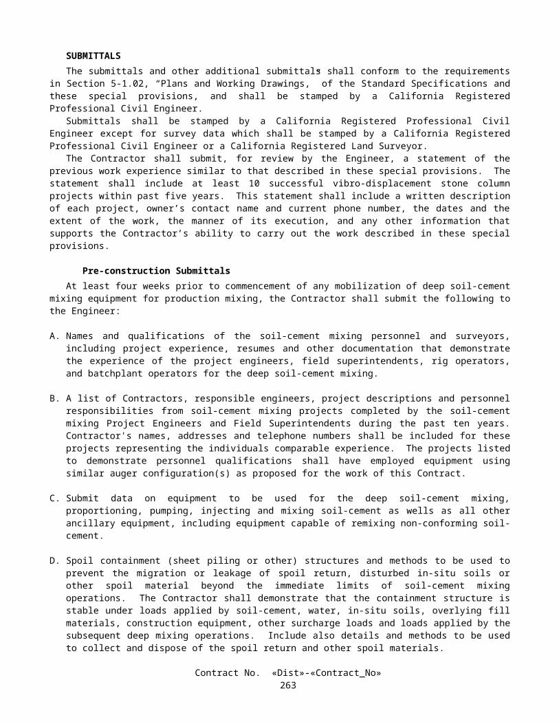
IRRIGATION SYSTEM COST BREAK-DOWN (Cont'd)
Contract No. 11-0301U4
UNIT DESCRIPTION UNITAPPROXIMATE
QUANTITY VALUE AMOUNT25 MM GATE VALVE EA 7
32 MM GATE VALVE EA 6
40 MM GATE VALVE EA 10
50 MM GATE VALVE EA 16
65 MM GATE VALVE EA 24
75 MM GATE VALVE EA 33
100 MM GATE VALVE EA 3
FERTILIZER COUPLING EA 6
25 MM PLASTIC PIPE (SUPPLY LINE) (PR-200) M 25 400
32 MM PLASTIC PIPE (SUPPLY LINE) (PR-200) M 4734
40 MM PLASTIC PIPE (SUPPLY LINE) (PR-200) M 5023
50 MM PLASTIC PIPE (SUPPLY LINE) (PR-200) M 4065
65 MM PLASTIC PIPE (SUPPLY LINE) (PR-200) M 6514
75 MM PLASTIC PIPE (SUPPLY LINE) (PR-200) M 8889
100 MM PLASTIC PIPE (SUPPLY LINE) (PR-200) M 2124
SPRINKLER (TYPE A-5) EA 441
SPRINKLER (TYPE A-7) EA 1032
SPRINKLER (TYPE A-8) EA 19
SPRINKLER (TYPE A-11) EA 633
SPRINKLER (TYPE A-12) EA 6
SPRINKLER (TYPE B-1) EA 43
SPRINKLER (TYPE B-2) EA 89
SPRINKLER (TYPE B-4) EA 32
SPRINKLER (TYPE C-2) EA 1872
TOTAL ____________________
Contract No. «Dist»-«Contract_No»266

Contract No. «Dist»-«Contract_No»267

10-2.02 EXISTING HIGHWAY PLANTINGIn addition to the provisions in Section 20 of the Standard Specifications, work performed in connection with existing
highway planting shall be in conformance with the provisions in Section 15, "Existing Highway Facilities," of the Standard Specifications and these special provisions.
Replacement planting shall conform to the requirements specified under "Preservation of Property" of these special provisions.
MAINTAIN EXISTING PLANTSExisting plants shall be maintained as directed by the Engineer. Maintaining existing plants will be paid for as extra
work as provided in Section 4-1.03D of the Standard Specifications.
REMOVE EXISTING GROUND COVERRemove existing groundcover shall consist of removing groundcover from the locations shown on the plans. Removed
ground cover shall be disposed of outside the highway right of way in conformance with the provisions in Section 7-l.13, "Disposal of Material Outside the Highway Right of Way," of the Standard Specifications.
Ground cover shall be removed in the same manner specified for clearing and grubbing in Section 16, "Clearing and Grubbing," of the Standard Specifications.
Holes or uneven ground resulting from groundcover removal shall be backfilled and graded to a smooth surface the same day the groundcover is removed. Soil from the surrounding area may be used to backfill the area. The backfill shall be graded to conform with the adjacent existing grade.
Remove existing ground cover will be measured by the square meter from the actual area where the existing ground cover was removed.
REMOVE EXISTING PLANTS FOR TRENCHINGRemoving existing plants for trenching shall conform to the provisions in Section 20-5.026, "Remove Existing Plants for
Trenching," of the Standard Specifications and these special provisions.Removing existing plants for trenching work shall consist of removing and replacing ground cover, pruning trees and
shrubs within trench locations, and disposing of removed ground cover and prunings.Replacement of removed ground cover within the maximum 1.8-m width, as specified in Section 20-5.026, "Remove
Existing Plants for Trenching," of the Standard Specifications, will not be required.Trees and shrubs adjacent to dikes, walks, fences, guard railing, and pavement edges may be pruned back 3 m from these
facilities to facilitate trenching work. When trenching is to be performed adjacent to other trees and shrubs that cannot be avoided, the trees and shrubs may be pruned upon receipt of prior written approval of the Engineer.
Pruning shall include removal of deadwood, suckers, and broken or bruised branches 25 mm or larger in diameter. Pruning shall conform to the provisions in Section 20-4.055, "Pruning," of the Standard Specifications.
Removed ground cover and pruned materials shall be disposed of outside the highway right of way in conformance with the provisions in Section 7-l.13, "Disposal of Material Outside the Highway Right of Way," of the Standard Specifications.
PRUNE EXISTING PLANTSExisting plants, as determined by the Engineer, shall be pruned. Pruning of the existing plants, except as otherwise
provided in these special provisions, will be paid for as extra work as provided in Section 4-1.03D of the Standard Specifications.
PRUNE EXISTING TREESExisting trees shown on the plans to be pruned shall be pruned in conformance with the provisions in Section 20-4.055,
"Pruning," of the Standard Specifications.Pruning shall include removal of deadwood, suckers, and broken or bruised branches 25 mm or larger in diameter.
Existing trees where shown on the plans to be pruned shall have their branches trimmed to a height of 1.2 m above original grade. Tree seal compounds shall not be used to cover pruning cuts.
The Contractor shall notify the Engineer 72 hours prior to the start of pruning existing trees.Removed pruned materials shall be disposed of outside the highway right of way in conformance to the provisions in
Section 7-l.13, "Disposal of Material Outside the Highway Right of Way," of the Standard Specifications. At the Contractor's option, prunings may be reduced to chips. Chipped materials shall be spread within the highway right of way where designated by the Engineer.
Contract No. «Dist»-«Contract_No»268

Payment for pruning plants as specified under "Remove Existing Plants for Trenching" and "Transplant Existing Trees" shall be in conformance to the provisions in these special provisions and shall not be considered as included in the payment for prune existing trees as provided in this section, "Prune Existing Trees."
10-2.03 EXISTING HIGHWAY IRRIGATION FACILITIESThe work performed in connection with the various existing highway irrigation system facilities shall conform to the
provisions in Section 15, "Existing Highway Facilities," of the Standard Specifications and these special provisions.Water shall be maintained in conformance with the provisions in Section 20-5.025, "Maintain Existing Water Supply,"
of the Standard Specifications.
CHECK AND TEST EXISTING IRRIGATION FACILITIESExisting irrigation facilities that are to remain or to be relocated, and that are within those areas where clearing and
grubbing or earthwork operations are to be performed, shall be checked for missing or damaged components and proper operation prior to performing clearing and grubbing or earthwork operations. Existing irrigation facilities outside of work areas that are affected by the construction work shall also be checked for proper operation.
A written list of existing irrigation system deficiencies shall be submitted to the Engineer within 5 working days after checking the existing facilities.
Deficiencies found during checking of the existing facilities shall be corrected as directed by the Engineer. Corrective work ordered by the Engineer will be paid for as extra work as provided in Section 4-1.03D of the Standard Specifications.
Existing backflow preventers shall be tested in conformance with the provisions in "Irrigation Systems" of these special provisions.
Length of watering cycles for use of potable water from water meters for checking or testing existing irrigation facilities shall be as determined by the Engineer.
Repairs to the existing irrigation facilities ordered by the Engineer after checking and testing the facilities, and further repairs required thereafter as ordered by the Engineer, except as otherwise provided for under "Maintain Existing Irrigation Facilities" of these special provisions, will be paid for as extra work as provided in Section 4-1.03D of the Standard Specifications.
MAINTAIN EXISTING IRRIGATION FACILITIESExisting irrigation facilities shall be maintained throughout the life of the contract. Prior to the start of maintaining
existing irrigation facilities work, the facilities shall be checked for proper operation, and repaired in conformance with the provisions in "Check and Test Existing Irrigation Facilities" of these special provisions.
After the existing facilities have been checked and repaired, the Contractor shall be responsible for the routine maintenance of existing irrigation systems. The work shall include, but not limited to, checking irrigation systems for proper operation and adjusting, repairing or replacing valves, valve boxes, sprinklers, risers, swing joints, wye strainers, valve assembly units, and filter assembly units.
The Contractor will not be responsible for maintaining existing water meters, underground pipe supply lines, control and neutral conductors, and electrical conduits. Except as otherwise specified in section "Existing Highway Irrigation Facilities" of these special provisions, repair work to these facilities ordered by the Engineer will be paid for as extra work as provided in Section 4-l.03D of the Standard Specifications.
Existing automatic irrigation systems shall be operated automatically during the life of the contract, except manual operation will be allowed for the work during plant replacement, fertilization, weed germination, and the repair of irrigation facilities.
Irrigation controllers shall be programmed by the Contractor for seasonal water requirements. During winter seasons irrigation systems shall be operated automatically a minimum of 2 minutes every 2 weeks.
Irrigation systems and facilities shall be checked for proper operation at least once every 30 days. When required, as determined by the Engineer, adjusting, repairing or replacing irrigation facilities shall be completed within 5 working days after checking the irrigation systems. Except as provided in these special provisions, repair and replacement of irrigation facilities shall conform to the provisions in "Existing Highway Irrigation Facilities" of these special provisions.
Except as provided in these special provisions, full compensation for maintaining existing irrigation facilities, including checking irrigation facilities, shall be considered as included in the contract lump sum price paid for irrigation system and no separate payment will be made therefor.
REMOVE EXISTING IRRIGATION FACILITIESExisting irrigation facilities where shown on the plans to be removed, shall be removed. Facilities that are more than
150 mm below finished grade, excluding facilities to be salvaged, may be abandoned in place.
Contract No. «Dist»-«Contract_No»269

Immediately after disconnecting an existing irrigation facility to be removed or abandoned from an existing facility to remain, the remaining facility shall be capped or plugged, or shall be connected to a new or existing irrigation facility.
Existing irrigation controllers, backflow preventers, valves, gate valves and sprinklers, where shown on the plans to be removed, shall be salvaged.
The Engineer shall be given written notification of the intent to salvage existing irrigation facilities a minimum of 72 hours prior to salvaging these facilities.
Salvaged irrigation facilities shall remain the property of the State and shall be delivered to the Engineer.A list of salvaged facilities, including the quantity and size of each item salvaged, shall be included with each delivery.Facilities to be removed, excluding facilities to be salvaged, shall be disposed of in conformance with the provisions in
Section 7-1.13, "Disposal of Material Outside the Highway Right of Way," of the Standard Specifications.
10-2.04 HIGHWAY PLANTINGThe work performed in connection with highway planting shall conform to the provisions in Section 20-4, "Highway
Planting," of the Standard Specifications and these special provisions.Attention is directed to "Order of Work," of these special provisions regarding time limits for completion of the
irrigation and planting installation at the Mitigation Site.Attention is directed to "Sound Control Requirements," of these special provisions regarding noise level restrictions for
work within the Mitigation Site.
HIGHWAY PLANTING MATERIALS
MulchMulch shall be wood chips.
Commercial Fertilizer (Slow Release)Commercial fertilizer (slow release) shall be a pelleted or granular form, shall be slow or controlled release with a
nutrient release over an 8- to 12-month period, and shall fall within the following guaranteed chemical analysis range:
Ingredient PercentageNitrogen 16-21Phosphoric Acid 6-8Water Soluble Potash 4-12
Commercial Fertilizer (Packets)Commercial fertilizer (packet) shall be slow or controlled release and shall be in a biodegradable packet form. The
packet shall gradually release nutrients over a 12-month period. Each packet shall have a mass of 10 g ± 1 g and shall have the following guaranteed chemical analysis:
Ingredient PercentageNitrogen 20Phosphoric Acid 10Water Soluble Potash 5
Commercial fertilizer (packet) will be measured by the actual count of packets in place.
ROADSIDE CLEARINGPrior to preparing planting areas, mulch areas, hydroseed and seeding areas, or commencing irrigation trenching
operations for planting areas, trash and debris shall be removed from the entire highway right of way within the project limits, excluding paved areas, medians and existing planted areas where existing plants are to remain.
In addition to removing trash and debris, the project area shall be cleared as specified herein:
A. Existing ground cover, where shown on the plans to be removed, shall be removed.B. Weeds shall be killed and removed within proposed ground cover areas and within the area extending beyond the
outer limits of the proposed ground cover areas to the adjacent edges of shoulders, dikes, curbs, sidewalks, walls, existing planting and fences. At those locations where proposed ground cover areas are 3.6 m or more from the adjacent edges of shoulders, dikes, curbs, sidewalks, walls, and fences, the clearing limit shall be 2 m beyond the outer limits of the proposed ground cover areas.
Contract No. «Dist»-«Contract_No»270

C. Weeds shall be killed and removed within proposed mulch areas and within the area extending beyond the outer limits of the proposed mulch areas to the adjacent edges of shoulders, dikes, curbs, sidewalks, walls, existing planting and fences. At those locations where proposed mulch areas are 3.6 m or more from the adjacent edges of shoulders, dikes, curbs, sidewalks, walls, and fences, the clearing limit shall be 2 m beyond the outer limits of the proposed mulch areas.
D. Weeds shall be killed and removed within planting areas where plants are to be planted in groups or rows 4.6 m or less apart and from within an area extending 2 m beyond the outer limits of the groups or rows of plants.
E. Weeds shall be killed and removed within an area 2 m in diameter centered at each plant location where the plants are to be planted more than 4.6 m apart and are located outside of ground cover areas.
F. Weeds shall be killed and removed within an area 0.6-m in diameter centered at each liner plant location where the plants are planted more than 3 m apart. At locations where liner plants are to be planted less than 3 m apart, weeds shall be killed and removed within the entire area.
G. Roadside clearing for hydroseed and seeding areas shall also consist of mowing weeds in the areas to be seeded until the start of the hydroseeding and seeding operations.
After the initial roadside clearing is complete, additional roadside clearing work shall be performed as necessary to maintain the areas, as specified above, in a neat appearance until the start of the plant establishment period. This work shall include the following:
A. Trash and debris shall be removed.B. Rodents shall be controlled.C. Weed growth shall be killed before the weeds reach the seed stage of growth or exceed 150 mm in length, except for
weeds in hydroseed and seeding areas to be mowed.D. Weeds in plant basins, including basin walls, shall be removed by hand pulling, after the plants have been planted.
Weed ControlWeed control shall also conform to the following:
A. Stolon type weeds shall be killed with glyphosate.B. Tumbleweeds shall be removed by hand pulling before the tumbleweeds reach a height of 150 mm.C. Removed weeds and ground cover shall be disposed of outside the highway right of way in conformance with the
provisions in Section 7-1.13, "Disposal of Material Outside the Highway Right of Way," of the Standard Specifications.
D. Areas to be mowed shall be mowed when weed height exceeds 300 mm. Weeds shall be mowed to a height of 50 mm to 150 mm.
Roadside clearing work shall not include work required to be performed as clearing and grubbing as specified in Section 16, "Clearing and Grubbing," of the Standard Specifications.
PESTICIDESPesticides used to control weeds shall conform to the provisions in Section 20-4.026, "Pesticides," of the Standard
Specifications. Except as otherwise provided in these special provisions, pesticide use shall be limited to the following materials:
DiquatGlyphosateOxadiazon - 50 percent WP (Preemergent)Oryzalin (Preemergent)Trifluralin (Preemergent)Ammonium Sulfate
Granular preemergents may be used when applied to areas that will be covered with mulch, excluding plant basins. Granular preemergents shall be limited to the following materials:
Oxadiazon (Preemergent)
Granular preemergents shall be applied prior to the application of mulch. Mulch applications shall be completed in these areas on the same working day. Photosensitive dye will not be required.
Contract No. «Dist»-«Contract_No»271

Glyphosate shall be used to kill stolon type weeds.Oxadiazon shall be of the emulsifiable concentration or wettable powder type, except when Oxadiazon is used under
mulch in conformance with these special provisions.Prior to the application of preemergents, ground cover plants shall have been planted a minimum of 3 days and shall
have been thoroughly watered.A minimum of 100 days shall elapse between applications of preemergents.Except for ground cover plants, preemergents shall not be applied within 450 mm of plants or within wild flower seeding
areas.Ammonium sulfate shall be used only in areas planted to Carpobrotus. Ammonium sulfate shall not be applied in a
manner that allows the pesticides to come in contact with trees or shrubs.If the Contractor elects to request the use of other pesticides on this project, the request shall be submitted, in writing, to
the Engineer not less than 15 days prior to the intended use of the other pesticides. Except for the pesticides listed in these special provisions, no pesticides shall be used or applied without prior written approval of the Engineer.
Pesticides shall not be applied within the limits of the plant basins. Pesticides shall not be applied in a manner that allows the pesticides to come in contact with the foliage and woody parts of the plants.
PLANTINGCommercial fertilizer and iron sulfate shall be applied or placed at the time of planting and at the rates shown on the
plans.A granular preemergent shall be applied to areas to be covered with mulch outside of plant basins in conformance with
the provisions in "Pesticides" of these special provisions.Mulch placed in areas outside of plant basins shall be spread to a uniform depth of 100 mm. An additional application of
mulch shall be placed during the third year of the plant establishment period under mass plantings of Acacia redolens.Mulch shall not be placed within one meter of the center line of earthen drainage ditches, within one meter of the edge of
paved ditches, and within one meter of the center line of drainage flow lines.Attention is directed to "Irrigation Systems Functional Test" of these special provisions regarding functional tests of the
irrigation systems. Planting shall not be performed in an area until the functional test has been completed for the irrigation system serving that area.
Commercial fertilizer packets shall be placed next to the plant to within 150 to 200 mm of the soil surface and approximately 22 mm from the roots.
Quantities of commercial fertilizer (packet) will be measured by the unit as determined from actual count in place.
LINER PLANTS (PLANT GROUP M)Liner plants shall be furnished in containers with a minimum size of 40 mm in diameter by 200 mm long. Liner plant
containers made of biodegradable material shall not be used. All liner plants shall be removed from their containers at the time of planting.
Liner plants shall be planted during the second year of the plant establishment period at the locations shown on the plans and as directed by the Engineer. Liner plants shall not be planted until the soil is moist to a minimum depth of 200 mm, unless otherwise approved in writing by the Engineer.
Planting holes for liner plants shall be large enough to accommodate the total length and width of the roots, commercial fertilizer packet, and soil amendments.
Full compensation for excavating plant holes for liner plants shall be considered as included in the contract unit price paid for plant (Group M) and no separate payment will be made therefor.
HYDROSEEDING Hydroseeding shall conform to the provisions in Section 20-3, "Erosion Control," of the Standard Specifications and
these special provisions.Hydroseeding work shall consist of site preparation and hydroseeding a mixture of fiber, seed, compost, commercial
fertilizer, stabilizing emulsion, bonded fiber matrix and water to areas shown on the plans as "Hydroseed 1", "Hydroseed 2" and "Hydroseed 3".
Pesticides shall not be used on hydroseeded areas after the seed has been applied.
Site PreparationImmediately prior to seeding hydroseed areas, trash and debris shall be removed, and weeds shall be killed and removed.
After killing and removing weeds and just prior to seed application, hydroseeded areas shall be scarified to a minimum depth of 25 mm.
Contract No. «Dist»-«Contract_No»272

Removed trash, debris, and weeds shall be disposed of outside the highway right of way in conformance with the provisions in Section 7-1.13, "Disposal of Material Outside the Highway Right of Way," of the Standard Specifications.
Materials shall conform to the provisions in Section 20-2, "Materials," of the Standard Specifications and these special provisions.
Contract No. «Dist»-«Contract_No»273
SeedSeed shall conform to the provisions in Section 20-2.10, "Seed," of the Standard Specifications. Individual seed species
shall be measured and mixed in the presence of the Engineer.Seed shall be delivered to the job site in unopened separate containers with the seed tag attached. Containers without a
seed tag will not be accepted.A sample of approximately 30 g of seed will be taken from each seed container by the Engineer.
Legume SeedLegume seed shall be pellet-inoculated or industrial-inoculated and shall conform to the following:
A. Pellet-inoculated seed shall be inoculated in conformance with the provisions in Section 20-2.10, "Seed," of the Standard Specifications.
B. Inoculated seed shall have a calcium carbonate coating.C. Pellet-inoculated seed shall be sown within 90 days after inoculation.D. Industrial-inoculated seed shall be inoculated with Rhizobia and coated using an industrial process by a
manufacturer whose principal business is seed coating and seed inoculation.E. Industrial-inoculated seed shall be sown within 180 calendar days after inoculation.F. Legume seed shall consist of the following:
LEGUME SEED(Hydroseed 1)
Botanical Name(Common Name)
Percent Germination(Minimum)
Kilograms Pure Live Seed Per Hectare (Slope Measurement)
Lotus scoparius(Deerweed)
35 1.5
Lupinus succulentus(Arroyo Lupine)
50 10
LEGUME SEED(Hydroseed 2)
Botanical Name(Common Name)
Percent Germination(Minimum)
Kilograms Pure Live Seed Per Hectare (Slope Measurement)
Lotus scoparius(Deerweed)
35 1.5
Lupinus succulentus(Arroyo Lupine)
50 10
LEGUME SEED(Hydroseed 3)
Botanical Name(Common Name)
Percent Germination(Minimum)
Kilograms Pure Live Seed Per Hectare (Slope Measurement)
Lotus scoparius(Deerweed)
35 1.5
Lupinus succulentus(Arroyo Lupine)
50 10
Contract No. «Dist»-«Contract_No»274

Non-Legume SeedNon-legume seed shall consist of the following:
NON-LEGUME SEED(Hydroseed 1)
Botanical Name(Common Name)
Percent Germination(Minimum)
Kilograms Pure Live Seed Per Hectare(Slope Measurement)
Artemisia californica(California Sage Brush
45 .25
Encelia californica(California Encelia)
35 2
Gnaphalium californicum(Green Everlasting)
20 .1
Stipa pulchra(Purple Needlegrass) (deawned)
35 3
Eriophyllum conferiflorum(Golden Yarrow)
35 .5
Salvia apiana(Whit Sage)
20 1
Salvia mellifera(Black Sage)
30 2
NON-LEGUME SEED(Hydroseed 2)
Botanical Name(Common Name)
Percent Germination(Minimum)
Kilograms Pure Live Seed Per Hectare(Slope Measurement)
Artemisia californica(California Sage Brush
45 .25
Encelia californica(California Encelia)
35 2
Eriophyllum conferiflorum(Golden Yarrow)
35 .5
Eschscholzia californica(California Poppy)
60 3
Stipa pulchra(Purple Needlegrass) (deawned)
35 3
Salvia mellifera(Black Sage)
30 1
Vulpia microstachys(Small Fescue)
35 5
NON-LEGUME SEED(Hydroseed 3)
Botanical Name(Common Name)
Percent Germination(Minimum)
Kilograms Pure Live Seed Per Hectare(Slope Measurement)
Artemisia californica(California Sage Brush
45 .25
Encelia californica(California Encelia)
35 2
Eriogonum fasciculatum(California Buckwheat)
35 2
Eschscholzia californica(California Poppy)
60 5
Contract No. «Dist»-«Contract_No»275

Commercial FertilizerCommercial fertilizer shall conform to the provisions in Section 20-2.02, "Commercial Fertilizer," of the Standard
Specifications and shall have a guaranteed chemical analysis of 6 percent nitrogen, 20 percent phosphoric acid and 20 percent water soluble potash.
CompostCompost shall be derived from green material consisting of chipped, shredded or ground vegetation or clean processed
recycled wood products or a Class A, exceptional quality biosolids composts, as required by the United States Environmental Protection Agency (EPA), 40 CFR, Part 503c regulations or a combination of green material and biosolids compost. The compost shall be processed or completed to reduce weed seeds, pathogens and deleterious material, and shall not contain paint, petroleum products, herbicides, fungicides or other chemical residues that would be harmful to plant or animal life. Other deleterious material, plastic, glass, metal or rocks shall not exceed 0.1 percent by weight or volume. A minimum internal temperature of 57˚C shall be maintained for at least 15 continuous days during the composting process. The compost shall be thoroughly turned a minimum of 5 times during the composting process and shall go through a minimum 90-day curing period after the 15-day thermophilic compost process has been completed. Compost shall be screened through a maximum 9.5-mm screen. The moisture content of the compost shall not exceed 35 percent. Moisture content shall be determined by California Test 226. Compost products with a higher moisture content may be used provided the weight of the compost is increased to equal the compost with a moisture content of 35 percent. Compost will be tested for maturity and stability with a Solvita test kit. The compost shall measure a minimum of 6 on the maturity and stability scale.
Stabilizing EmulsionStabilizing emulsion shall conform to the provisions in Section 20-2.11, "Stabilizing Emulsion," of the Standard
Specifications and these special provisions. Stabilizing emulsion shall be nonflammable and shall have an effective life of at least one year.
Stabilizing emulsion shall be in a dry powder form, may be reemulsifiable, and shall be a processed organic adhesive used as a soil tackifier.
Bonded Fiber MatrixBonded fiber matrix shall be a hydraulically applied erosion control blanket comprised of wood fibers and stabilizing
emulsion.The matrix shall be pre-mixed and pre-packaged by the manufacturer and composed of wood fiber, with a minimum 25
percent of the fibers averaging 10 mm long. Fibers shall be colored with a water-soluble, non-toxic dye, The matrix shall disperse rapidly in water and remain in uniform suspension under agitation to form a homogeneous slurry.
Bonded fiber matrix, when applied, shall form a continuous moisture-holding mat with no hole greater than one mm in size, shall have no gaps between mat and soil, and have a water holding capacity of 10 liters per kilograms of matrix. Bonded fiber matrix shall not inhibit seed germination and growth.
Possible sources and acceptable BFM products available:
Conwed 3000Available at: Hydroscape (619) 440-4703
435 Marshall Avenue, El Cajon, CA 92020
Eco-Aegis Rep Dave Kopp (509)220-2473Available at: Ewing Irrigation (619) 426-5200
591 C Street, Chula Vista, CA 91910Kalmia Sales (909) 693-5512P.O. Box 1165, Temecula, CA 92593S & S Seeds (805) 684-0436P.O. Box 1275, Carpenteria, CA
Soil Guard Rep: Lucinda J. Dustin (916) 564-6717Available at: Verdant Resources, LLC
3026 Swallows Nest DriveSacramento, CA 95833
Contract No. «Dist»-«Contract_No»276

HYDROSEED 1 APPLICATIONHydroseed materials shall be applied in two separate applications in the following sequence:
A. The following mixture in the proportions indicated shall be applied with hydro-seeding equipment within 60 minutes after the seed has been added to the mixture:
Material Kilograms Per Hectare(Slope Measurement)
Fiber 1000Non-Legume Seed 8.85Legume Seed 11.5Compost 800
B. The following mixture in the proportions indicated shall be applied with hydro-seeding equipment:
Material Kilograms Per Hectare(Slope Measurement)
Fiber 700Compost 1000Commercial Fertilizer 25Stabilizing Emulsion (Solids) 150
HYDROSEED 2 APPLICATIONHydroseed materials shall be applied in two separate applications in the following sequence:
A. The following mixture in the proportions indicated shall be applied with hydro-seeding equipment within 60 minutes after the seed has been added to the mixture:
Material Kilograms Per Hectare(Slope Measurement)
Fiber 1000Non-Legume Seed 14.75Legume Seed 11.5Compost 800
B. The following mixture in the proportions indicated shall be applied with hydro-seeding equipment:
Material Kilograms Per Hectare(Slope Measurement)
Fiber 700Compost 1000Commercial Fertilizer 25Stabilizing Emulsion (Solids) 150
HYDROSEED 3 APPLICATIONHydroseed materials shall be applied in two separate applications in the following sequence:
A. The following mixture in the proportions indicated shall be applied with hydro-seeding equipment within 60 minutes after the seed has been added to the mixture:
Material Kilograms Per Hectare(Slope Measurement)
Bonded Fiber Matrix 2250Non-Legume Seed 9.25Legume Seed 11.5
Contract No. «Dist»-«Contract_No»277

B. The following mixture in the proportions indicated shall be applied with hydro-seeding equipment The first application should be sufficiently dry in accordance with the manufacturer's recommendations, prior to applying the second application:
Material Kilograms Per Hectare(Slope Measurement)
Bonded Fiber Matrix 2250Commercial Fertilizer 50
Contract No. «Dist»-«Contract_No»278
PLANT ESTABLISHMENT WORKThe plant establishment period shall be Type 2 and shall be not less than 750 working days.Hydroseeding and seeding not performed prior to the start of the plant establishment period shall be performed during
the plant establishment period. The work involved in preparing areas to receive hydroseeding and seeding and applying seed shall be in conformance with the provisions in "Hydroseeding" and Seeding" of these special provisions.
Plant establishment work for hydroseed 1, hydroseed 2, hydroseed 3, seeding (Type 1), and seeding (Type 2)_areas shall consist of killing and removing weeds, trash and debris removal.
Attention is directed to "Relief From Maintenance and Responsibility" in these special provisions regarding relief from maintenance and protection.
Commercial fertilizer (slow release) shall be applied to trees, shrubs, vines and ground cover during the first week of May and November of each year. Commercial fertilizer shall be applied at the rates shown on the plans and shall be spread with a mechanical spreader wherever possible.
The center to center spacing of replacement plants for unsuitable ground cover plants shall be determined by the number of completed plant establishment working days at the time of replacement and the original spacing in conformance with the following:
ORIGINAL SPACING (Millimeters)
SPACING OF REPLACEMENT GROUND COVER PLANTS(Millimeters)
Number of Completed Plant Establishment Working Days1-125 126-190 191-End of Plant
Establishment300 300 230 150
During the plant establishment period, the plants shall be watered utilizing the Remote Irrigation Control System (RICS) software program, and the automatic solar irrigation controllers. A seasonal watering schedule shall be submitted to the Engineer during the first week of April, July and November for use during the plant establishment period.
During the plant establishment period, the Mitigation Site shall be watered utilizing the automatic solar irrigation controller. During the first two years of the plant establishment period the plants in the Mitigation Site shall be watered to encourage plant roots to reach for the water table. During the third year of the plant establishment period water applied to the plants in the Mitigation Site shall be gradually reduced so that the plants can become self sufficient. A seasonal watering schedule shall be submitted to the Engineer during the first week of April, July and November for use during the plant establishment period.
Weeds within plant basins, including basin walls and ground cover, shall be controlled by hand pulling.The Contractor shall notify the Engineer 2 working days prior to beginning weed removal work within the mitigation
site. The Biologist shall be consulted regarding the identification of the types of weed species to be removed.Weeds within mulched and ground cover areas and outside of plant basins shall be controlled by killing.Weeds outside of mulched areas, plant basins, ground cover, the median, and paved areas shall be controlled by mowing. Vines shall be trained onto walls.At the option of the Contractor, plants of a larger container size than those originally specified may be used for
replacement plants during the first 125 working days of the plant establishment period. The use of plants of a larger container size than those originally specified for replacement plants shall be at the Contractor's expense.
After 125 working days of the plant establishment period have been completed, replacement of plants, except for ground cover plants, shall be No. one size for seedlings, pot and liner size plants; No. 5 size for No. one size plants; No. 15 size for No. 5 size plants; and other plant replacement plants shall be the same size as originally specified.
When ordered by the Engineer, one application of a preemergent pesticide conforming to the provisions in "Pesticides" of these special provisions, shall be applied between 40 and 50 working days prior to completion of the plant establishment period. This work will be paid for as extra work as provided in Section 4-1.03D of the Standard Specifications.
The final inspection shall be performed in conformance with the provisions in Section 5-1.13, "Final Inspection," of the Standard Specifications and shall be completed a minimum of 20 working days before the estimated completion of the contract.
10-2.05 IRRIGATION SYSTEMSIrrigation systems shall be furnished and installed in conformance with the provisions in Section 20-5, "Irrigation
Systems," of the Standard Specifications, except materials containing asbestos fibers shall not be used.Attention is directed to "Order of Work" of these special provisions regarding time limits for completion of the irrigation
installation for the Mitigation Site.
Contract No. «Dist»-«Contract_No»279

Attention is directed to the provisions in "Obstructions" of these special provisions, regarding work over or adjacent to existing underground facilities. Excavation for proposed irrigation facilities shall not be started until the existing underground facilities have been located.
Pipe supply lines shall be pressure tested in conformance with the provisions in Section 20-5.03H, "Pressure Testing," of the Standard Specifications, except the pipe (supply line) on the discharge side of the control valve shall be tested by Method B as specified in Section 20-5.03H(2), "Method B," of the Standard Specifications.
Only pipeline trenches and excavation pits for supply lines being supplied from one water service point shall be open at one time. After pressure testing is complete, trenches and pits excavated for pipe supply lines, being supplied from one water service point, shall be backfilled prior to commencing excavations for pipe supply lines being supplied from another water service point.
Gate valves, 75 mm and larger in size, shall be furnished with a square lug and shall be operated by use of long shank keys. Prior to acceptance of the contract, 3 long shank keys shall be delivered to the Engineer.
Gate valves 75 mm and larger in size shall be flanged type gate valves and shall have a solid bronze or brass wedge.Pipe flanges used to connect plastic or metal pipe to gate valves shall be metal.
VALVE BOXESValve boxes shall conform to the provisions in Section 20-2.24, "Valve Boxes," of the Standard Specifications, except as
otherwise provided herein.Valve boxes shall be precast portland cement concrete, fiberglass or reinforced plastic.Covers for concrete valve boxes shall be glass fiber reinforced plastic, plastic, or concrete.Covers for plastic valve boxes shall be glass fiber reinforced plastic or plastic.Valve boxes shall be identified on the top surface of concrete covers by stenciling with paint the appropriate
abbreviations for the irrigation facilities contained in the valve boxes as shown on the plans. Valve boxes that contain remote control valves shall be identified by the appropriate letters and numbers (controller and station numbers). The letters and numbers shall be 50 mm in height. The stenciling paint shall be a commercial quality, epoxy resin base paint of a color which contrasts with the valve box covers.
Valve boxes shall be identified on the top surface of glass fiber reinforced plastic or plastic covers by branding the appropriate abbreviations for the irrigation facilities contained in the valve boxes as shown on the plans. Valve boxes that contain remote control valves shall be identified by the appropriate letters and numbers (controller and station numbers). The letters and numbers shall be 50 mm in height.
RE-LABEL EXISTING VALVE BOX COVERRe-label existing valve box cover shall include furnishing, labeling and installing a new remote control valve box cover
at an existing valve box location where indicated on the plans.Valve box covers and labeling shall conform to the provision in “Valve Boxes,” elsewhere in these special provisions.New valve box covers shall be labeled with the valve and controller information shown on the plans.
ELECTRIC AUTOMATIC IRRIGATION COMPONENTS
Irrigation ControllersThe Remote Irrigation Control System (RICS) irrigation controllers shall be Rain Bird Maxicom controllers and shall
communicate by cellular interface.Arrangements have been made to insure that any successful bidder can obtain the specified equipment listed below from
United Green Tech, formerly Pacific Technical Services, 23372 South Pointe Drive, Suite B, Laguna Hills, California, 92653, telephone (949) 837-4737.
Contract No. «Dist»-«Contract_No»280

The quoted prices and equipment are as follows:
EQUIPMENT DESCRIPTION QUOTED PRICE SALES TAX EXTENDED PRICE QUANTITYAT THIS PRICE
28 Channel CCUModel No. C28 RMOP28 Channel Cluster Control Unit with Radio, Modem, Omni Antenna Pole Assembly, Rain Shut Off Assembly, Line Primary Protection, Cellular Interface Cable and Frequency Submittals.
$9,976.00 $773.00 $10,749.00 1
40 Station Irrigation ControllerModel No. RB2-40 ESP 40 Station Satellite Controller with Radio, Modem LoPro Antenna Assembly, Master Valve Relays Line, Primary Protection, TRC Connector and Cable Kit, TRC Quick Connect Antenna Connector.
$4,061.00 $315.00 $4,376.00 2
32 Station Irrigation ControllerModel No. RB2-32 ESP 32 Station Satellite Controller Assembly with Radio, Modem, LoPro Antenna Assembly, Master Valve Relays, Line Primary Protection and TRC Quick Connect Antenna Connector
$3,841.00 $298.00 $4,139.00 2
24 Station Irrigation ControllerModel No. RB2-24 ESP 24 Station Satellite Controller Assembly with Radio, Modem, LoPro Antenna Assembly, Master Valve Relays, Line Primary Protection and TRC Quick Connect Antenna Connector.
$3,462.00 $268.00 $3,730.00 2
24 Station Irrigation ControllerModel No. RB2-24 ESP 24 Station Satellite Controller Assembly with Cluster Adapter Module, TRC Connector and Cable Kit and Master Valve Relays.
$2,134.00 $165.00 $2,299.00 2
12 Station Irrigation ControllerModel No. RB2-12 ESP 12 Station Satellite Controller Assembly with Cluster Adapter Module, TRC Connector and Cable Kit, and Master Valve Relays.
$1,824.00 $141.00 $1,965.00 1
Hand Held Remote ControlModel No. TRC-XRECHand Held Remote Control, TRC Transmitter and Receiver Kit, and Francis Antenna Kits
$2,045 $158 $2,203 1
Contract No. «Dist»-«Contract_No»281

Prices are guaranteed by United Green Tech, formerly Pacific Technical Services for one year from the date of the quote, January 12, 2001. Prices include tax.
The contract unit price paid for the above listed equipment shall include full compensation for furnishing all labor, materials, tools, equipment, and incidentals, and for doing all the work involved in providing and installing the system, complete in place, as shown on the plans, as specified in these special provisions, and as directed by the Engineer.
The contract unit price paid for hand held remote control shall include full compensation for furnishing all labor, materials, tools, equipment, and incidentals, and for doing all the work involved in providing hand held remote control, complete in place, as shown on the plans, as specified in these special provisions, and as directed by the Engineer.
The state furnished irrigation controller shall be installed in an existing irrigation controller cabinet in accordance with the details shown on the plans, and at the location indicated on the plans
Attention is directed to the provisions in Section 10-3, "Signals, Lighting and Electrical Systems," of these special provisions, regarding electrical power for irrigation controllers and irrigation controller enclosure cabinets.
The solar automatic irrigation controllers shall conform to the following:
A. Photovoltaic 6-station and 12-station irrigation controllers, photovoltaic power system, computer with lockable, waterproof, vandal resistant case, shall each be manufactured as one complete unit.
B. All power will be provided by an internal photovoltaic system. Power shall be available for continuous 24-hour operation under the minimum light equivalent to 25 percent of ambient light at 55 degrees latitude.
C. The computer liquid-crystal display will be powered by a 9 V battery key mechanism.D. The irrigation controller shall have an output digital control pulse at 3.5 V which will operate a valve solenoid
actuator within 300 m distance.E. Irrigation controller shall be fully automatic and capable of operating a complete one day to 90 day cycle,
scheduling up to 32 totally independent programs, each having its own start time, day cycle, assigned stations, duration, and program time. Each station shall be capable of 1 minute to 24 hours in one minute increments with separate setting for hours and minutes.
F. Irrigation controller shall have an emergency program backup system with a user-defined fail-safe program and system parameters which are stored in non-erasable memory.
G. Irrigation controller shall be installed on a vertical mounting tube, mounted as shown on the plans and in accordance with the manufacturer's specifications.
H. Low voltage control and neutral conductors and splice connectors shall be manufactured by the same company.I. The watering time of each station shall be displayed on the face of the control panel.
Each irrigation controller shall be enclosed in a stainless steel enclosure with inside mounted hinges and an inside mounting clamp. Enclosure shall be equipped with a stainless steel lock. Prior to acceptance of the contract, 2 keys shall be delivered to the Engineer.
Electric Remote Control ValvesElectric remote control valves shall conform to the provisions in Section 20-2.23, "Control Valves," of the Standard
Specifications and the following:
A. Valves shall be glass filled nylon, brass, or bronze construction.B. Valves shall be angle pattern (bottom inlet) or straight pattern (side inlet) as shown on the plans.C. Valve solenoids for (solar/battery) controller shall be DC latching and operate on 3.5 V and shall be compatible with
the irrigation controller.D. Relays for remote control valves (master) shall be installed in the controller cabinet as recommended by the
manufacturer.
Pull BoxesPull box installations shall conform to the provisions in Section 20-5.027I, "Conductors, Electrical Conduits and Pull
Boxes," of the Standard Specifications.
ConductorsLow voltage, as used in this section "Conductors," shall mean 36 V or less.Low voltage control and neutral conductors in pull boxes and valve boxes, at irrigation controller terminals, and at
splices shall be marked with adhesive cloth wrap-around markers.
Contract No. «Dist»-«Contract_No»282

Markers for the control conductors shall be identified with the appropriate number or letter designations of irrigation controllers and station numbers. Markers for neutral conductors shall be identified with the appropriate number or letter designations of the irrigation controllers.
New control and neutral conductors that are to replace existing control and neutral conductors shall be the same size and color as the existing control and neutral conductors being connected to.
The color of low voltage neutral and control conductor insulation, except for the striped portions, shall be homogeneous throughout the entire thickness of the insulation.
Insulation for conductors may be UL listed polyethylene conforming to UL44 test standards with a minimum insulation thickness of 1.05 mm for wire sizes 10AWG and smaller.
At the option of the Contractor, other types of splice sealing materials and methods may be used provided other materials and methods have been approved in writing by the Engineer prior to installation of the connectors.
Flow Sensor CableFlow sensor cable shall be UL listed as Type TC and meet the requirements of ICEA/NEMA, 600-V control cable,
90°C, and the following:
A. The cable shall consist of two No. 16, minimum, stranded copper conductors. Each conductor shall be insulated with 0.48-mm, minimum nominal thickness, color coded, polypropylene or polyethylene material. Color coding shall distinguish each conductor.
B. The shield shall be either tinned copper braid or aluminized polyester film with a nominal 20 percent overlap. Where the film is used, a No. 18 or larger, stranded, tinned, copper drain wire shall be placed between the insulated conductors and the shield and in contact with the conductive surface of the shield.
C. The jacket shall be black polyvinyl chloride with minimum ratings of 600 V and 90°C and a minimum nominal thickness of 1.25 mm. The cable jacket shall be marked with the manufacturer’s name or trademark, insulation type designation, number of conductors and conductor size, and voltage and temperature ratings.
D. The finished outside diameter of the cable shall not exceed 8.9 mm.E. The capacitance, as measured between any conductor and the other conductors and the shield, shall not exceed 88 pf
per meter at 1000 Hz.F. The cable run between remote control valve (master) with flow meter and the irrigation controller shall be
continuous without splices.
RE-CIRCUIT EXISTING IRRIGATION CONTROLLERSRe-circuiting the existing irrigation controllers shall consist of relocating the existing remote control valve wires from
one station location to another on the terminal strip inside the irrigation controller cabinet.Existing remote control valve wires shall be moved to the location on the terminal wiring strip that corresponds to the
new valve number as shown on the plans.Work to re-circuit existing irrigation controllers shall be done in conformance with the plans, the provisions in Section
20-5.027, "Electrical Installations for Electric Automatic Irrigation Systems," of the Standard Specifications and these special provisions.
REMOTE CONTROL VALVE (MASTER) WITH FLOW METERRemote control valve (master) with flow meter shall be installed in accordance with the details shown on the plans and
the requirements of these special provisions.The remote control valve (master) with flow meter shall consist of a remote control valve with flow meter, flow sensor
cable, and all appurtenances required to complete the installation as shown on the plans.The master remote control valve with flow meter shall be a globe type valve, consisting of diaphragm actuated hydraulic
control valve with 0.3 amp, 3-way solenoid control and built-in impeller type flow meter and brass pressure regulating pilot. Remote control valves (master) shall normally be closed.
The valves shall conform to the following:
A. Valves shall be pressure rated to 1206 kPa and shall be equipped with 8-volt, cast iron, flange type end connections which conform to ANSI Standard: B16.1, Class 125.
B. Magnetically driven vertical turbine impeller flow meters shall be accurate to plus or minus 2 percent of the actual flow.
C. Flow meters shall be equipped with an electric pulse transmitter for remote monitoring, factory preset to provide a pulse signal every 3.8 liters. Flow meter 50 mm in size shall have a flow range between 45 and 567 liters per minute.
D. Valves shall operate on the 24-volt AC voltage supplied from the irrigation controller or controllers.Contract No. «Dist»-«Contract_No»
283

E. Main valve bodies and covers shall be of cast iron construction with internal and external epoxy coatings.F. Valve shall be equipped with brass fitting and copper tubing.G. Both magnetic drive control head and meter register shall be vacuum sealed.
Flow sensor cable and two low voltage conductors shall be installed in conduit between each master remote control valve with flow meter and irrigation controller as shown on the plans. Flow sensor cable shall conform to the provisions in "Flow Sensor cable," elsewhere in these special provisions.
IRRIGATION SYSTEMS FUNCTIONAL TESTFunctional tests for the remote irrigation controller system (RICS) and associated automatic irrigation systems shall
conform to the provisions in Section 20-5.027J, "Testing," of the Standard Specifications and these special provisions.Two functional tests shall be performed, one without and one with connection to the remote irrigation controller system
base station. Both tests shall consist of demonstrating to the Engineer, through one complete cycle of the irrigation controllers in the automatic mode, that the associated automatic components of the irrigation systems operate properly.
The Contractor shall notify the Engineer not less than 2 weeks prior to starting the functional tests for the remote irrigation control system.
The existing remote irrigation controller system base station is located in the District Water Manager's office at 4120 Taylor Street, San Diego, CA 92110, (619) 688-3332.
Associated automatic components for both tests shall include, but not limited to, new and existing remote control valve actuator systems, irrigation controllers, remote control valves, conductors, flow sensors, and rain sensors. Associated automatic components for the second test shall include, but not be limited to, new and existing irrigation software programs, cellular phone systems, hand held remote controls, local two way radio communication between CCU and satellite units, and flow alarms for high and, zero mainline flows.
The first test shall be performed prior to planting the plants and shall consist of testing the irrigation controllers and associated automatic irrigation systems without connection to the remote irrigation controller system base station. Upon completion of a satisfactory functional test, and correction of the deficiencies, the plants to be planted in the areas watered by the irrigation system may be planted, provided the planting areas have been prepared as specified in these special provisions.
The second test shall be performed prior to the start of plant establishment and shall consist of testing the irrigation controllers (field units) and associated automatic irrigation systems with connection to the remote irrigation controller system base station. As part of the second test, a remote irrigation controller system watering schedule shall be submitted for each irrigation controller (field unit) to the Engineer. The Engineer will enter the watering schedule into the irrigation software program, and a computer printout will be made available to the Contractor for verification. If the Engineer determines the submitted watering schedule is unacceptable, a revised watering schedule shall be submitted to the Engineer for approval within 5 working days. Also as part of the second test, the Contractor shall demonstrate to the Engineer that the remote irrigation controller system base station detects and reports the high, low, zero, and maximum mainline flow alarms. Upon completion of a satisfactory test, including correction of deficiencies, the plant establishment period may begin, provided planting work as specified in these special provisions has been completed except for plant establishment work.
If new automatic components of the irrigation systems, including remote irrigation controller system base station components, fail a functional test, the components shall be repaired. Repairs shall be at the Contractor's expense. Testing shall be repeated until satisfactory operation is obtained.
Repair or replacement of existing irrigation facilities due to unsatisfactory performance shall conform to the provisions in Section 20-5.025, "Maintain Existing Water Supply," of the Standard Specifications and "Existing Highway Irrigation Facilities" of these special provisions.
PIPE
Copper PipeCopper pipe shall be seamless, Type K hard drawn tubing.Copper pipe supply lines installed between water meters and backflow preventer assemblies shall be installed not less
than 450 mm below finished grade, measured to the top of the pipe.
Plastic PipePlastic pipe supply lines shall be polyvinyl chloride (PVC) 1120 or 1220 pressure rated pipe with the minimum pressure
rating (PR) 200.Plastic pipe supply lines and fittings that are 75 mm or larger in diameter on the supply side of control valves shall be the
rubber ring gasket type, except when pressure rating (PR) 315 plastic pipe supply line is required.
Contract No. «Dist»-«Contract_No»284
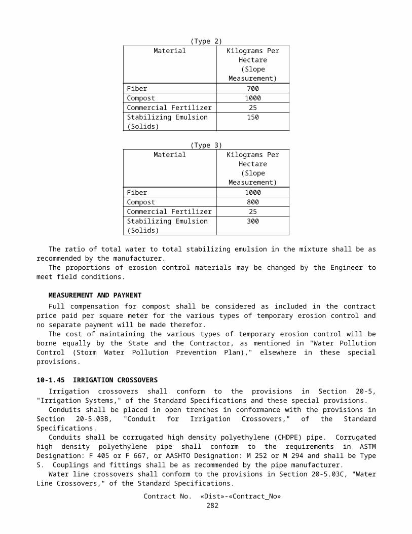
Plastic pipe supply lines less than 75 mm in diameter shall have solvent cemented type joints. Primers shall be used on the solvent cemented type joints.
Plastic pipe supply lines (main) shall have a minimum cover of 0.45 m.Fittings for plastic pipe supply lines with a pressure rating (PR) of 315 shall be Schedule 80.
WATER METERWater meters for the irrigation systems will be furnished and installed by the serving utility at the locations shown on the
plans.The Contractor shall make the arrangements and pay the costs and fees required by the serving utility.The City of San Diego Municipal Water District has established fees of $24,000.00 for furnishing and installing a 50 mm
water meter, and $19,000.00 for furnishing and installing a 40 mm water meter. If, at the time of installation, this fee has been changed, the State will take a credit for the reduction in the fee, or the State will pay the difference for the increase in the fee. The credit or payment will be taken or paid on the first monthly progress payment made after the meter is installed. The Contractor shall furnish the Engineer with a copy of the invoice for the installation fee.
The quantity of water meters will be measured by the unit as determined from actual count in place.The contract unit price paid for water meter shall include full compensation for furnishing all labor, materials, tools,
equipment, and incidentals, and for doing all the work involved in furnishing and installing water meters, complete in place, as shown on the plans, as specified in the Standard Specifications and these special provisions, and as directed by the Engineer.
BACKFLOW PREVENTER ASSEMBLIESBackflow preventers shall conform to the provisions in Section 20-2.25, "Backflow Preventers," of the Standard
Specifications and these special provisions.Pressure loss through the backflow preventers shall not exceed the following:
BACKFLOW PREVENTER SIZE(millimeters)
FLOW RATE(Liters per minute)
PRESSURE LOSS(kPa)
50 7 30
Backflow preventer assemblies shall be painted with a minimum of 2 applications of a commercial quality enamel paint. The color of the paint shall be light brown.
When backflow preventer assembly enclosures are specified, the portland cement concrete pads for the enclosures will be paid for in conformance to the provisions in "Backflow Preventer Assembly Enclosures" of these special provisions.
BACKFLOW PREVENTER ASSEMBLY ENCLOSUREEnclosures shall be fabricated of structural steel angles and flattened expanded metal and shall be installed over
backflow preventer assemblies on a portland cement concrete pad as shown on the plans and in conformance with these special provisions.
Expanded metal for sides, ends and top panels shall be fabricated from No 9 expanded metal. The flattened expanded metal openings shall be approximately 20 mm by 45 mm in size.
Expanded metal panels shall be attached to the steel frames by a series of welds, not less than 6.4 mm in length and spaced not more than 100 mm on centers, along the edges of the enclosure.
Enclosure door handles shall have provisions for padlocking in the latched position. Padlocks will be State-furnished. Attention is directed to "State-furnished Materials" of these special provisions.
Enclosures shall be galvanized, after fabrication, in conformance with the provisions in Section 75-1.05, "Galvanizing," of the Standard Specifications.
Concrete for the concrete pad shall conform to the provisions in Section 20-2.26, "Concrete," of the Standard Specifications.
Hold down bolt assemblies shall be galvanized and shall be installed when the portland cement concrete pad is still plastic. Nuts shall be hexagonal and washers shall be the lock type.
Enclosures shall be painted with one application of a commercial quality pre-treatment, vinyl wash primer and a minimum of two applications of a commercial quality, exterior enamel for metal. The finish color shall be light brown.
All parts of the backflow preventer assembly enclosure, including hold down assemblies, may be constructed of stainless steel instead of standard steel materials specified above. Stainless steel enclosures shall conform to the provisions herein except galvanizing, priming and painting shall not be required. Stainless steel enclosures shall be powder coated a light brown color by the manufacturer.
Contract No. «Dist»-«Contract_No»285

The minimum clearance between the backflow preventer assembly and the backflow preventer assembly enclosure shall be 50 mm. The concrete pad shall extend a minimum of 50 mm beyond the outer limits of the backflow preventer assembly enclosure, unless otherwise shown on the plans or specified in these special provisions.
The quantity of backflow preventer assembly enclosures will be measured by the unit as determined from actual count in place.
TESTING BACKFLOW PREVENTERSNew backflow preventers installed by the Contractor and existing backflow preventers to remain in place shall be tested
for proper operation in conformance with the provisions in Section 20-5.03J, "Check and Test Backflow Preventers," of the Standard Specifications and these special provisions.
Tests for new backflow preventers shall be satisfactorily completed after installation of the backflow preventer assembly and before operation of the irrigation systems. Existing backflow preventers shall be tested, and repaired if required, when existing irrigation facilities are checked.
Repair of existing backflow preventers will be paid for as extra work as provided in Section 4-1.03D of the Standard Specifications when ordered by the Engineer, except damage caused by the Contractor's operations.
New and existing backflow preventers shall be retested one year after the satisfactory completion of the previous test. Testing shall be performed on an annual basis throughout the life of the contract or 10 days prior to completion of the plant establishment period, whichever occurs first.
Testing existing backflow preventers will be paid for in conformance with the provisions in "Checking and Testing Existing Irrigation Facilities" of these special provisions.
SPRINKLERSSprinklers shall conform to the type, pattern, material, and operating characteristics listed in the "Sprinkler Schedule"
shown on the plans.
FERTILIZER COUPLINGFertilizer coupling shall be in accordance with the details shown on the plans and the requirements of these special
provisions.The fertilizer coupling shall consist of an aluminum cam and groove coupling with dust cap, gate valve and all piping
required to complete the assembly in place as shown on the plans.
FINAL IRRIGATION SYSTEM CHECKA final check of existing and new irrigation facilities shall be performed not more than 20 working days prior to
acceptance of the contract.The length of watering cycles using potable water measured by water meters for the final check of irrigation facilities
will be determined by the Engineer.Remote control valves connected to existing and new irrigation controllers shall be checked for automatic performance
when the controllers are in automatic mode.Unsatisfactory performance of irrigation facilities installed or modified by the Contractor shall be repaired and rechecked
at the Contractor's expense until satisfactory performance is obtained, as determined by the Engineer.Repair or replacement of existing irrigation facilities due to unsatisfactory performance shall conform to the provisions
in "Existing Highway Irrigation Facilities" of these special provisions.Nothing in this section "Final Irrigation System Check" shall relieve the Contractor of full responsibility for making
good or repairing defective work or materials found before the formal written acceptance of the entire contract by the Director.
Full compensation for checking the irrigation systems prior to the acceptance of the contract shall be considered as included in the contract lump sum price paid for plant establishment work and no additional compensation will be allowed therefor.
SECTION 10-3. SIGNALS, LIGHTING AND ELECTRICAL SYSTEMS
10-3.01 DESCRIPTIONSignal and lighting, lighting and sign illumination, changeable message sign system, irrigation controller enclosure
cabinet, electric service (irrigation), ramp metering systems, traffic monitoring stations, lighting conduit (bridge), remove ramp metering system, and fiber optic communication system shall conform to the provisions in Section 86, "Signals, Lighting and Electrical Systems," of the Standard Specifications and these special provisions.
Lighting equipment is included in the following structures:Contract No. «Dist»-«Contract_No»
286

A. Bridge No. 57-0314 - Carmel Mountain Road Undercrossing (Widen)B. Bridge No. 57-0314S - Carmel Mountain Road Undercrossing (Outer Right)C. Bridge No. 57-0511 - Los Penasquitos Channel Bridge (Widen and Retrofit)D. Bridge No. 57-0512 - Route 5/805 Separation (Widen)E. Bridge No. 57-1070G - N805/N5 Truck ConnectorF. Bridge No. 57-513R/L ViaductG. Bridge No. 57-1028F - Southbound 5 Truck Connector
Communication conduit is included in the following structures:
A. Bridge No. 57-0314S - Carmel Mountain Road Undercrossing (Outer Right)B. Bridge No. 57-0512 - Route 5/805 Separation (Widen)C. Bridge No. 57-513R/L ViaductD. Bridge No. 57-1070G - N805/N5 Truck Connector
Traffic signal work shall be performed at the following locations:
A. Location 1 - Route 5 Northbound Off Ramp at Carmel Mountain RoadB. Location 2 - Route 5 Southbound Off Ramp at Carmel Mountain Road
Ramp Metering System work shall be performed at the following locations:
A. Location 1 - Route 5 Northbound On Ramp at Carmel Mountain RoadB. Location 2 - Route 5 Southbound On Ramp at Carmel Mountain RoadC. Location 3 - Route 56 Westbound from El Camino Real to Carmel Creek Road
10-3.02 COST BREAK-DOWNCost break-downs shall conform to the provisions in Section 86-1.03, "Cost Break-Down," of the Standard
Specifications and these special provisions.The Engineer shall be furnished a cost break-down for each contract lump sum item of work described in this Section
10-3.The cost break-down shall be submitted to the Engineer for approval within 15 days after the contract has been
approved. The cost break-down shall be approved, in writing, by the Engineer before any partial payment for the items of electrical work will be made.
The cost breakdown shall include the following items in addition to those listed in the Standard Specifications:
A. Fiber Optic VaultsB. Fiber Distribution UnitsC. Splice ClosuresD. Hub CabinetsE. Cable - each size and type
10-3.03 MAINTAINING EXISTING AND TEMPORARY ELECTRICAL SYSTEMSTraffic signal and ramp metering systems shutdowns shall be limited to periods allowed for lane closures listed or
specified in "Maintaining Traffic" of these special provisions.
10-3.04 TEMPORARY LIGHTINGThe temporary lighting shall consist of installing and maintaining temporary lighting in conformance with the details
shown on the plans, the provisions in "Maintaining Traffic" of these special provisions, the provisions in Section 86, "Signals, Lighting and Electrical Systems," of the Standard Specifications, and these special provisions.
The provisions in this section shall not relieve the Contractor from the responsibility to provide the additional devices or take the measures as may be necessary to conform to the provisions in Section 7-1.09, "Public Safety," of the Standard Specifications.
Other materials and equipment for temporary lighting including, but not limited to, wood poles, conductors, and hardware shall be furnished by the Contractor.
Materials and equipment to be used in the temporary lighting shall be either new or used suitable for the intended use.
Contract No. «Dist»-«Contract_No»287

CONDUCTORS AND WIRINGConductors shall be the types specified in Section 86-2.08, "Conductors," of the Standard Specifications or shall be
Type UF cable.Conductors to be placed outside of paved areas shall be placed by one of the following methods:
A. Direct burial method with Type UF cable installed at a minimum depth of 600 mm below grade.B. Placed in Type 3 conduit. When Type 3 conduit is used, the minimum depth shall be 450 mm.C. Suspended from wood poles with a minimum clearance at any point of 3 m. Conductors on the pole within 3 m
above ground shall be enclosed in a Type 3 or Type 4 conduit.
BONDING AND GROUNDINGStandards with metal bases shall be mechanically and electrically secure to form a continuous system effectively
grounded by the grounding conductor.Generator neutral grounding shall conform to the provisions for multiple service points in Section 86-2.10, "Bonding and
Grounding," of the Standard Specifications.
SERVICEAt the option of the Contractor, one of the following methods shall be used to provide power for the temporary lighting:
A. Obtain commercial power from an existing utility company.B. A generator system with an additional generator as a backup.
COMMERCIAL POWERPower sources shall be protected in locked enclosures. The Engineer shall be provided with keys to all locks.Power shall not be obtained from private parties, other than a direct connection to a utility company service point.Electrical power may be used from existing highway facilities.The Contractor shall make arrangements with the utility company for providing service. The cost to provide the
commercial power shall be at the expense of the Contractor.Commercial electrical power is available at the work site.
GENERATORGenerators shall be 120-V or 120/240-V, 60 Hz, 2.5 kW minimum, continuous duty type. Generators may be powered
by gasoline, LPG or diesel engines operating at approximately 1800 revolutions per minute. Engines shall be provided with automatic oil feed. Generator system shall be equipped to provide automatic start-stop operation, with 12-V starting system. Generator output circuit shall have overcurrent protection with a maximum setting of 15 A or as shown on the plans.
Fuel storage shall be sufficient for periods of time during which the generator system will be operated unattended.Engines shall be equipped with approved spark arresters.
GENERATOR OPERATIONTwo generators shall be provided. A single generator shall operate the system. In the event of a failure to supply
voltage for the system, the second generator shall start automatically and transfer the system load upon reaching operating voltage.
SALVAGING TEMPORARY LIGHTINGUpon completion of the work requiring temporary lighting, as determined by the Engineer, electroliers shall be salvaged.Other materials and equipment shall become the property of the Contractor and shall be disposed of in conformance with
the provisions in Section 7-1.13, "Disposal of Materials Outside the Highway Right of Way," of the Standard Specifications. Pole holes shall be backfilled.
Direct buried conductors, installed 300 mm or more below the ground surface, and conduit may be abandoned in place.
PAYMENTFull compensation for temporary lighting shall be considered as included in the contract lump sum price paid for lighting
and sign illumination and no separate payment will be made therefor.
Contract No. «Dist»-«Contract_No»288

10-3.05 FOUNDATIONSWhere cast-in-drilled-hole concrete pile foundations are to be constructed in slag aggregate embankments, the diameter
of the pile shall be increased to provide a minimum of 75 mm of concrete cover over the reinforcing steel.Full compensation for the increased diameter of cast-in-drilled-hole concrete pile foundations in slag aggregate
embankments, including additional portland cement concrete, and increased drilling and placement costs shall be considered as included in the contract lump sum price paid for the item requiring the cast-in-drilled-hole concrete pile foundation and no additional compensation will be allowed therefor.
10-3.06 STANDARDS, STEEL PEDESTALS AND POSTSThe length of the 60 mm diameter or 50 mm standard pipe tenon on the end of new mast arms receiving low pressure
sodium (LPS) luminaires shall not be less than 380 mm nor greater than 457 mm.The sign mounting hardware shall be installed at the locations shown on the plans.The sign panels will be State-furnished in conformance with the provisions in "Materials" of these special provisions.Type 1 standards shall be assembled and set with the handhole on the downstream side of the pole in relation to traffic or
as shown on the plans.
10-3.07 CONDUITConduit to be installed underground shall be Type 3 unless otherwise specified. Pull ropes for empty conduits for future use shall be a soft fiber type of not less than 12 mm diameter.The conduit in a foundation and between a foundation and the nearest pull box shall be Type 3.Conduit to be installed in concrete barrier shall be Type 3 unless otherwise specified. Conduit sizes shown on the plans and specified in the Standard Specifications and these special provisions are referenced
to metallic type conduit. When rigid non-metallic conduit is required or allowed, the nominal equivalent industry size shall be used as shown in the following table:
Size Designation for Metallic Type Conduit Equivalent Size for Rigid Non-metallic Conduit21 2027 2541 4053 5063 6578 75103 100
When Type 3 conduit is placed in a trench (not in pavement or under portland cement concrete sidewalk), after the bedding material is placed and the conduit is installed, the trench shall be backfilled with commercial quality concrete, containing not less than 250 kg of portland cement per cubic meter, to not less than 100 mm above the conduit before additional backfill material is placed.
Multiduct conduit system (MDCS) trench and backfill requirements shall be as shown on the plans and as described elsewhere in these special provisions.
Conduit runs shown on the plans to be located behind curbs may be installed in the street, within 0.9-m of, and parallel with the face of the curb, by the "Trenching in Pavement Method" in conformance with the provisions in Section 86-2.05C, "Installation," of the Standard Specifications. Pull boxes shall be located behind the curb or at the locations shown on the plans.
After conductors have been installed, the ends of conduits terminating in pull boxes, vaults, service equipment and other enclosures, telephone demarcation cabinets, hub cabinets and in controller cabinets shall be sealed with an approved type of sealing compound.
All conduits shall be cleaned with a mandrel or cylindrical soft bristled brush and blown out with compressed air until all foreign material is removed immediately prior to sealing empty conduits or installing cables. Cleaning shall be performed in the presence of the Engineer. The ends of conduits shall be sealed with an approved sealing compound. The ends of multiduct conduit system shall be sealed with sealing plugs as described elsewhere in these special provisions.
At those locations where conduit is required to be installed under pavement and existing underground facilities require special precautions in conformance with the provisions in "Obstructions" of these special provisions, conduit shall be placed by the "Trenching in Pavement Method" in conformance with the provisions in Section 86-2.05C, "Installation," of the Standard Specifications.
At other locations where conduit is required to be installed under pavement and if a delay to vehicles will not exceed 5 minutes, conduit may be installed by the "Trenching in Pavement Method."
Contract No. «Dist»-«Contract_No»289

At the option of the Contractor, the final 0.6-m of conduit entering a pull box in a reinforced concrete structure may be Type 4.
10-3.08 MULTIDUCT CONDUIT SYSTEMWhere multiduct conduit system (MDCS) is shown on the plans a factory assembled conduit system shall be used. The
system shall be of the following types as shown on the plans:
Contract No. «Dist»-«Contract_No»290

A. A Size 103 conduit with four Size 25 (I.D. nominal) conduits contained therein. Joints shall be keyed to mate the enclosed conduits.
B. Size 32 (I.D. nominal) high density polyethylene conduits. Attention is directed to "High Density Polyethylene (HDPE) Conduit" elsewhere in these special provisions.
Size 103 conduit to be installed underground shall be Type 3 unless otherwise specified. Conduit on bridge structures shall be fiberglass unless otherwise shown on the plans except that the conduit contained within size 103 conduits may be Type 3.
The quantity of Size 25 or Size 32 conduits shall be as shown on the plans.Size 103 conduits (and conduits contained within) and Size 32 conduits shall be either all individually factory color
coded or all orange, except that fiberglass conduits shall be gray. Straight segments of Type 3 and fiberglass multiduct conduit shall be nominal 6 m lengths.
In MDCS using Size 103 conduits, joints shall be solvent welded or sealed with a gasket as recommended by the manufacturer. Joints shall lock together or be provided with a seating mark to verify proper assembly.
Bends shall be rigid factory assembled sections designed to fit the system.The minimum conduit bend radius shall not be less than 1.8 m.
10-3.09 COMMUNICATION CONDUITAt the locations shown on the plans, where communication conduit is to be installed on bridges, fiberglass conduit shall
be used and shall conform to the details shown on the plans, and in these special provisions.
Fiberglass ConduitFiberglass conduit and components shall conform to the requirements in ANSI/NEMA Standards Publication TC-14A or
TC-14B. The fiberglass conduit components shall be free of defects including delaminations and foreign inclusions. The fiberglass conduit components shall be nominally uniform (as commercially practical) in color, density, and physical properties. Fiberglass conduit shall be straight and the ends shall be cut square and true. The Contractor shall purchase all fiberglass conduit and other fiberglass conduit system components from the same manufacturer to insure component compatibility.
Fiberglass conduit shall be manufactured in 6 m minimum lengths.Fiberglass conduit components shall include compatible fittings, adapters, expansion joints, and factory bends at nominal
radii of 0.6 m, 1 m, and 1.3 m for Size 53, 78, and 103 conduits, respectively.The fiberglass conduit system components shall be produced from heat cured, corrosion resistant epoxy resin and
continuous fiberglass rovings. The materials shall be manufactured for use at temperatures from -40˚C to 110˚C. The fiberglass conduit components shall be manufactured using a homogeneously dispersed UV inhibitor. When exposed to direct sunlight, the UV inhibitor shall prevent the degradation of the physical material properties, except for surface cosmetic appearance. Materials shall contain no halogens above trace levels and shall be fire resistant.
Joints shall be water tight and withstand a minimum of 4450 N of pullout tension.For all sizes of fiberglass conduit, under a load of 1.3 kN/m of conduit, the deflection of the inside diameter shall not
exceed 5 percent.The minimum impact resistance values for the fiberglass conduit shall be as follows when measured in conformance
with the requirements in ASTM D2444-70, using a 9 kg tup "B" with a 50 mm radius nose:
Size 53 conduit 40 N•mSize 78 conduit 68 N•mSize 103 conduit 108 N•m
10-3.10 HIGH DENSITY POLYETHYLENE CONDUIT
GENERALHigh density polyethylene (HDPE) conduit for communications applications shall conform to the details shown on the
plans, these special provisions, and as directed by Engineer.
MATERIALHigh density polyethylene conduit shall be manufactured from high density polyethylene virgin compounds.High density polyethylene compounds used in the manufacture of communication conduit shall conform to the following
Cell Classifications specified in ASTM Designation: D 3350:
Contract No. «Dist»-«Contract_No»291

Property Cell ClassificationDensity 3Melt index 3 or 4Flexural modulus 5Tensile strength 4Environmental stress crack resistance 3Hydrostatic design basis 0, 1, 2, 3 or 4Ultraviolet stabilizer Cb
b HDPE resin shall contain not less than 2 ±0.5 percent carbon black ultraviolet stabilizer.
CONDUITHigh density polyethylene conduit size and location shall be as shown on plans. Conduit shall be the smooth interior
wall type.High density polyethylene conduit shall be suitable for cable and conductor installation methods as described in Section
86 of the Standard Specifications, in these special provisions, and in "Air Blown Method" as described elsewhere in these special provisions.
High density polyethylene conduit color shall be black with orange colored stripe. Orange colored stripe shall consist of not less than 2 stripes, with longitudinal orientation, evenly spaced.
Conduit shall contain carbon black ultraviolet shielding suitable for the conduit to sustain unprotected outdoor exposure for at least one year.
Conduit shall be continuously marked with clear, distinctive and permanent markings at intervals not greater than 2 m. The marking shall be in a contrasting color to the conduit color. The height of the marking shall be approximately 2.5 mm or larger. Conduit marking information shall include, as a minimum, the following information:
A. Nominal SizeB. Dimension Ratio (DR)C. Manufacturer Name and Product/Model NumberD. Material CodeE. Plant IdentificationF. Production Date
Coils and reels shall have sequential measurement markings every meter.High density polyethylene conduit shall be DR 9 per ASTM D3035 for controlled outside diameter.High density polyethylene conduit shall be IPS outside diameter controlled in accordance with the manufacturer's
production tolerances. The wall thickness of DR or SDR sized conduit shall be in accordance with the manufacturer's production tolerances.
Contract No. «Dist»-«Contract_No»292

High density polyethylene conduit shall meet or exceed the following:
PROPERTY TEST METHOD (ASTM unless shown otherwise)
UNIT VALUE (Nominal)
Material Classification D 3350 PE33 or PE34Density D 1505 g/cm3 0.941Flow Rate D 1238 g/10 Min. 0.40Flexural Modulus D 790 MPa 55
Tensile Strength D 638 MPa 20.6
Environmental Stress Crack Resistance
D1693 Hours Meet Cell Classification 3
HDB @ 73.4 Degrees F D 2837 MPa Meet Cell Classification 0, 1, 2, 3 or 4
UV Stabilizer D 1603 %C not less than 2Hardness D 2240 Shore D 64Elongation D 638
(2"/Min.)%, minimum 750
Modulus of Elasticity D 638 MPa 862
Impact Strength D 256Thermal Expansion Coefficient
D 696 mm/mm/°C 1.44x10⁻⁴
Thermal Conductivity C177 kcal/m2/hr/°C 13.1
Brittleness Temperature D 746 °C <-118
Vicat Softening Temperature
D 1525 °C 123
JOINING OF CONDUITConduit shall be joined by heat fusion. Heat fusion (includes electrofusion) of high density polyethylene conduit shall be
by methods recommended by the conduit manufacturer, and with equipment approved for the purpose. Equipment shall not expose conduit to direct flame. Heat fusion shall be performed by conduit manufacturer certified or authorized personnel. A minimum of 2 test fusions, by each fusion operator, shall be demonstrated to the Engineer prior to performing fusion operations on any high density polyethylene conduit to be installed.
INSTALLATIONHigh density polyethylene conduit shall be installed at underground locations only.In addition to the conduit installation methods for Type 3 Conduit, as described in Section 86 of the Standard
Specifications and in these special provisions, high density polyethylene conduit may be installed by Horizontal Directional Drilling (HDD) (per ASTM F1962 "Standard Guide for Use of Maxi-Horizontal Directional Drilling for Placement of Polyethylene Pipe or Conduit Under Obstacle, Including River Crossings") or "Directional Boring Method" as described elsewhere in these special provisions. Where there is a difference or conflict between requirements, the higher of the two standards shall apply.
Conduit bends, except factory bends, shall have a radius of not less than the manufacturer's recommended minimum bend radius. Where factory bends are not used, conduit shall be bent, without crimping or flattening, using the longest radius practicable.
Contract No. «Dist»-«Contract_No»293

Bending of high density polyethylene conduit shall be by methods recommended by the conduit manufacturer, and with equipment approved for the purpose. Equipment shall not expose conduit to direct flame.
Attention is directed to "Conduit" elsewhere in these special provisions regarding cleaning and sealing conduit.The ends of high density polyethylene conduit shall be capped until the installation of cable is started.A pull rope, conforming to Section 86-2.05C, "Installation," of the Standard Specifications shall be installed in conduits
which are to receive future conductors
CERTIFICATES OF COMPLIANCE, MATERIALS RECEIVING INSPECTION AND MANUFACTURER'S DATAIn conformance with the provisions in Section 6-1.07, "Certificates of Compliance," a Certificate of Compliance shall be
furnished to the Engineer for each type of high density polyethylene conduit furnished. The certificate shall also certify that the high density polyethylene conduit complies with the requirements of these special provisions, and shall include the resin material Cell Classification, unit mass of pipe, average pipe stiffness and date of manufacture.
Conduit, when delivered to the site, which exhibits damage in excess of 10 percent of the conduit wall thickness may be rejected by the Engineer. Conduit exhibiting damage which does not meet the manufacturer's recommendations for usable conduit may also be rejected by the Engineer. Conduit sections may be repaired if approved by the Engineer. Replacement or repair of rejected conduit shall be at the Contractor's expense.
Two copies of the manufacturer's product technical specification information shall be furnished to the Engineer at least two weeks subsequent to the start of the scheduled delivery.
Two copies of the manufacturer's test data for the delivered shipment shall be furnished to the Engineer at the time of the delivery.
10-3.11 SEALING PLUGExcept as otherwise noted, multiduct conduit system and Size 103 conduits shall have their ends sealed with commercial
preformed plugs which prevent the passage of gas, dust and water into the multiduct conduit system and Size 103 conduits.Sealing plugs shall be removable and reusable. Plugs sealing conduit, conductor or cable shall be the split type that
permits installation or removal without removing conductors or cables. Sealing plugs shall be capable of withstanding a pressure of 34.5 kPa.
Sealing plugs that seal MDCS (Size 103) shall seal the conduit and all enclosed conduits simultaneously with one self contained assembly having an adjustable resilient filler of neoprene or silicone rubber clamped between backing ends and compressed with stainless steel hardware.
Sealing plugs that seal the Size 25 or Size 32 conduits of MDCS shall seal each conduit individually with appropriate sizes and configuration to accommodate either empty conduit or those containing cable. Suitable sealing between the varying size cables and the plugs shall be provided by inserting split neoprene or silicone adapting sleeves, used singularly or in multiples, within the body of the plugs, or an equivalent method approved by the Engineer.
A sealing plug that seals an empty conduit shall have an eye or other type of capturing device (on the side of the plug that enters the conduit) to attach onto the pull tape so the pull tape will be easily accessible when the plug is removed.
10-3.12 TRACER WIRETracer wire shall be provided and placed in the trench over conduits containing fiber optic cable. The wire shall be
placed 50 mm above the uppermost conduit in the trench or secured to the top of the uppermost conduit in the trench.Tracer wire shall be No. 8 stranded, minimum, copper conductor with Type TW, THW, RHW, or USE insulation. The
tracer wire shall form a mechanically and electrically continuous line throughout the length of the trench. A minimum of 1.5 m of slack shall be extended into each pull box and fiber optic vault from each direction. The wires shall be carefully placed so as not to be damaged by backfilling operations.
Conduit entering or exiting a reinforced concrete structure will not require tracer wire to the first pull box or vault.Tracer wire may be spliced at intervals of not less than 150 m.
10-3.13 WARNING TAPEWarning tape shall be provided and placed in the trench over conduits as shown on the plans. The warning tape shall be
100 mm wide with bold printed black letters of approximately 19 mm on bright orange color background, and contain the printed warning "CAUTION CALTRANS FIBER OPTIC LINE BURIED BELOW", repeated at approximately 800 mm intervals.
The printed warning shall be non-erasable and shall be rated to last with the tape for a minimum of 40 years.The construction of the warning tape shall be such that it will not delaminate when it is wet. It shall be resistant to
insects, acid, alkaline and other corrosive elements in the soil. It shall have a minimum of 712 N tensile strength per 150 mm wide strip and shall have a minimum of 700 percent elongation before breakage.
Contract No. «Dist»-«Contract_No»294

10-3.14 SLURRY CEMENT BACKFILLThe slurry cement backfill for the installation of multiduct conduit system or other conduit as shown on the plans (except
on bridge structures) shall conform to the provisions in Section 19, "Earthwork," of the Standard Specifications and these special provisions.
The size of the aggregate shall not be larger than 9.5 mm.The concrete shall be pigmented a medium to dark, red or orange color by the addition of commercial quality cement
pigment to the concrete mix. The red or orange concrete pigment shall be LM Scofield Company; Orange Chromix Colorant; Davis Colors; or equal.
Full compensation for furnishing and incorporating the cement pigment to achieve the color required shall be considered as included in the contract price or prices paid per meter for the conduit involved and no separate payment will be made therefor.
10-3.15 DIRECTIONAL BORING METHODWhere jacking and drilling is shown on the plans as the required installation method, conduits may be installed by the
directional boring method. Directional boring shall not be used at other locations unless approved by the Engineer. All pull boxes or vaults shall be located at the locations shown on the plans.
Minimum depth of conduit below finished grade in pavement areas shall be 2.5 m.A listing of materials (composition and strength) and methods used in directional boring shall be submitted for the
Engineer’s review.The diameter of the boring tool shall not exceed 1.5 times the outside diameter of the conduit. Mineral slurry or wetting
solution shall only be used to lubricate the boring tool and to stabilize the soil surrounding the boring path. Mineral slurry or wetting solution shall be water based and environmentally safe.
Residue from directional boring operations shall be handled in the same manner as residue from slot cutting operations described in Section 86-5.01A(5), "Installation Details," of the Standard Specifications.
The directional boring equipment shall have directional control of the boring tool and have an electronic boring tool location detection system. During operation, the directional boring equipment shall be able to determine the location of the tool both horizontally and vertically.
The directional boring equipment shall be equipped with a tension measuring device that indicates the amount of tension exerted on conduit during conduit pulling operations.
Slurry cement backfill and warning tape, as shown on the plans for trench installations of conduit, are not required where the directional boring method is used. Tracer wire shall be attached to the uppermost conduit prior to conduit installation.
A representative of the Contractor must be in direct charge and control of the directional boring operation at all times.The Engineer shall be notified in writing 2 working days in advance of starting directional boring operations. The
location and equipment to be used in the boring operation shall be included in the advance notice to the Engineer. Directional boring shall only be performed in the presence of the Engineer unless otherwise notified in writing by the Engineer.
Full compensation for directional boring shall be considered as included in the contract unit or lump sum price paid for the conduit involved and no additional compensation will be allowed therefor.
10-3.16 PULL BOXESGrout shall not be placed in the bottom of pull boxes.Where the sump of an existing pull box is disturbed by the Contractor's operation, the sump shall be reconstructed as
shown on Standard Plan ES-8.
10-3.17 FIBER OPTIC VAULTFiber optic vaults shall conform to the Western Underground Committee Guide No. 3.6, "Nonconcrete Enclosures,"
except where noted in these special provisions, and shown on the plans.Covers shall be the non-skid type. Cover marking shall be "CALTRANS FIBER OPTICS" on each cover. Each cover
shall have inset lifting pull slots. Cover hold down bolts or cap screws and nuts shall be of brass, stainless steel, or other non-corroding metal material.
A reinforced concrete encasement ring shall be poured around the collar of the fiber optic vault as shown on the plans. The concrete for encasement ring shall contain not less than 325 kg of cement per cubic meter.
Fiber optic vaults and covers shall be rated for AASHTO HS 20-44 loads and be installed as detailed and where shown on the plans.
Hanger assemblies shall consist of not less than 3 hangers evenly distributed. Hangers shall be made of a non -corroding material and be free of any sharp edges. A separate hanger assembly shall be provided for a minimum of eight fiber optic
Contract No. «Dist»-«Contract_No»295
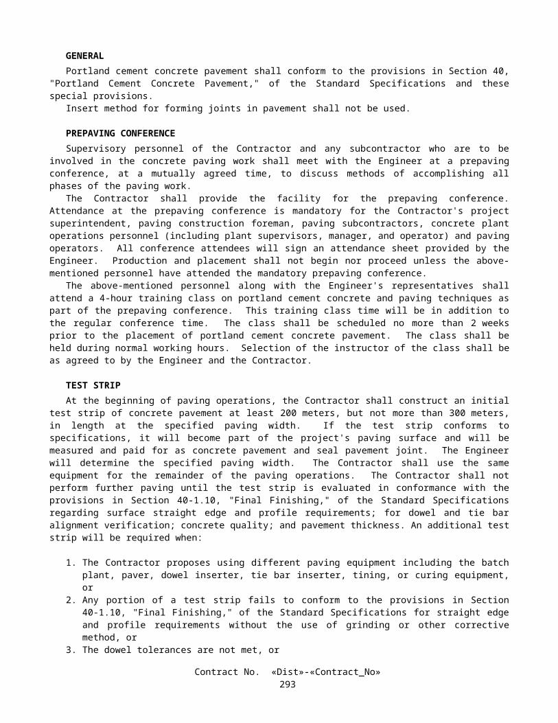
cables and be securely fastened to the side wall with the slack fiber optic cable neatly coiled.The Contractor shall not install additional fiber optic vaults over those shown on the plans without the Engineer’s written
approval.
10-3.18 HUB CABINETThe hub cabinet consists of a prefabricated aboveground milled steel structure with an in-ground concrete basement
conforming with the details shown on the plans and as specified in these special provisions or as directed by the Engineer. The structure shall be pre-manufactured by a company normally engaged in the fabrication of controlled environmental structures. Nominal 12 gauge thick sheeting shall be used for the milled steel structure. The hub cabinet shall be rated at not less than Nema 3R.
The hub cabinet shall include the following equipment:
1) Single phase, 3-wire circuit main breaker panel board equipped with provisions for 6 circuit breakers.2) Interior lighting consisting of ceiling-mounted fixtures (containing two 1.2 m 40 W fluorescent lamps) at the
approximate locations shown on the plans and shall conform to the following specifications:
a) Contain a motion detector sensor. In addition to a test switch, the motion detector circuit shall have an override switch for manual operation.
b) Fully automatic operation, motion is detected and shall continue to operate for 10 minutes minimum after no motion is detected.
3) Emergency lighting shall consist of a 2-bulb, battery operated light and shall conform to the following specifications:
a) Completely self-contained with an external test switch and wired to operate when commercial power fails.b) Able to operate continuously for 2 hours minimum under full charge.c) Contain a maintenance free battery with a 10-year rated life.d) Lamps shall be glare-free sealed beam PAR 36.e) Charger shall be solid state and feature an automatic low voltage disconnect and operate on 120 V.
4) A 250 W sump pump with two float switches and drain placed as shown on the plans.5) Water level indicator and alarm system.6) High Humidity Alarm.7) Intrusion Alarm - Local audio shall be a siren rated at 100 dB, 3200 Hz, piezo type with an adjustable delay. The
alarm system and components shall be tamper resistant and installed in the hub cabinet. The intrusion alarm sensor shall automatically reset to the active state once the entranceway cover is closed.
8) High and Low Temperature Alarm9) Commercial Power Alarm (failure).10) Smoke Alarm - The smoke detector shall be a photoelectric smoke detector with built-in siren and battery back-up.11) Step ladder rated Type 1 and fabricated from aluminum or steel. The ladder shall be secured to the cabinet structure.12) Commercial quality EIA 482 mm racks of the quantity, dimension and placement as shown on the plans.13) Splice ladders of the dimension and configuration shown on the plans.14) Air conditioners, of the quantity shown on the plans, thermostatically controlled to provide a minimum capacity of
12 000 BTU each.
The cabinet shall be equipped to maintain an interior ambient temperature range of 16°C to 24°C.Interior walls shall be insulated with an R-7 foil type insulation.Convenience outlets for 120 V components are shown on the plans.An emergency power input connector shall be located on the outside of the structure adjacent to the entranceway. The
connector shall be enclosed in a weatherproof housing and shall consist of a 100 A, 3-pole, 4-wire connector rated at 120/240 V.
The hub structure shall be designed to meet the following structure requirements, in addition to those shown on the plans:
Design Loading: Roof, 2.39 kPa; Floor, 11.97 kPa; Wind, 128 km/hr; and Seismic, Zone 4.
EARTHWORK.--Earthwork shall conform to the provisions of Section 19, "Earthwork," of the Standard Specifications and these special provisions. If the manufacturer's requirements for installation of the hub cabinet exceeds those provisions
Contract No. «Dist»-«Contract_No»296

of Section 19 of the Standard Specifications, the more rigorous requirements shall apply.Excess material removed as "Structure Excavation" shall be utilized in embankment construction or disposed of outside
the highway right of way in accordance with the provisions in Section 7-1.13, "Disposal of Material Outside the Highway Right of Way," of the Standard Specifications.
ELECTRICAL.--All electrical work for the hub cabinet shall conform to the provisions in Section 86, "Signals, Lighting and Electrical Systems," of the Standard Specifications and these special provisions.
The hub cabinet shall be wired for a 100 A, 60-cycle, 3-wire, 120/240-V single phase service.The alarm features provided in the hub cabinet shall provide local audio and visual indicators and remotely be connected
to an alarm terminal port for connection to the transportation management center, as shown on the plans and described in these special provisions. The following is a list of alarm contact closures (rated at 110 V, 2 A minimum) and conditions for the alarms, that shall be provided showing the status of the hub cabinet:
1) Water level indicator and alarm system- activated by the float switch on the sump pump.2) High Humidity Alarm - activated over an adjustable humidity range, set between 20 to 85 percent.3) Intrusion Alarm - activated whenever the entranceway cover is opened.4) High and Low Temperature Alarm - activated over an adjustable high temperature range between 26°C to 45°C and
an adjustable low temperature range between 0°C to 24°C.5) Commercial Power Alarm (failure) - activated whenever commercial power is interrupted for more than 6 cycles.6) Smoke Alarm - activated whenever smoke or fire is detected in the hub cabinet.
The contact closures for these alarms shall be connected to a terminal block in the enclosure.
DOOR AND DOOR HARDWARE.--Door shall be right-hand or left-hand swing. The door shall have provisions for opening the door from the interior of the cabinet without the use of tools.
Door shall be equipped with weather-stripping, butt hinges, lockset, door stop, and threshold.Weather-stripping shall be installed on both sides and the top of the door.Lockset cylinder shall be keyed to match a sample key supplied by the Engineer.Door and frame shall be installed rigidly, securely, plumb, and true. The door shall operate free without rubbing or
binding. Clearance between the frame and door shall be not more than 3-mm.Hardware items shall be accurately fitted, securely applied, and adjusted in accordance with the manufacturers'
instructions.Hardware items shall be removed from surfaces to be painted during painting.
EXTERIOR.--The milled steel enclosure interior and exterior shall be prepared, primed with an epoxy primer, and finish painted with an acrylic urethane enamel or equal. The finish color shall be tan.
Below ground exterior surfaces shall be coated with a protective seal suitable for the underground installations according to the following requirements:
1) All coatings shall be the best quality grade of specified types as regularly manufactured by a recognized coating manufacturer.
2) Coatings shall be applied only when surfaces are dry and properly prepared and the surrounding conditions are satisfactory for coating. Surfaces shall be cleaned of all dust, dirt, grease, wax, loose coatings, and other substances that would impair bonding of the coating.
WARRANTY.--Hub cabinet workmanship shall be covered by a warranty of not less than one year.
10-3.19 CATHODIC PROTECTIONCathodic protection system components including electrical connections and anodes shall be furnished and installed in
accordance with the details shown on the plans and as specified in these special provisions. Cathodic protection equipment shall be suitable for the equipment to be protected and manufactured by a manufacturer who is now regularly engaged in the manufacture of cathodic protection equipment.
LOCATION OF CATHODIC PROTECTION.—The locations of cathodic protection equipment, devices, outlets and appurtenances as shown on the plans are approximate only. Exact locations shall be determined by the Contractor subject to the approval of the Engineer.
SUBMITTALS.—The Contractor shall submit a list of the cathodic equipment, materials, and installation methods for approval by the Engineer. The submittal shall include, but not be limited to:
1) Hub enclosure manufacturer’s approval of the proposed cathodic protection system.Contract No. «Dist»-«Contract_No»
297

2) Engineering drawing showing the proposed cathodic protection layout.3) Cathodic protection materials (description and quantity).4) Description of the cathodic protection materials (including anode composition and weight).5) Cathodic protection installation methods (including weld type and quantity to connect anode leads to equipment).6) Cathodic protection system manufacturer’s testing methods, list of recommended testing equipment and acceptable
range of results for individual components.7) Cathodic protection system manufacturer’s certification that the components provided are as described in function,
composition and performance.
Catalog cut sheets, bulletins, brochures or data sheets shall be submitted for items of material or equipment for which shop drawings are not available. Catalog cut sheets, bulletins, brochures or data sheets are not required to be submitted for miscellaneous items of hardware which are needed to accomplish this work and which are not specifically covered in these specifications.
CAUTION TAPE.—Red Caution tape 75-mm in width shall be installed above buried wire and conduits at a maximum depth of 305-mm below grade over the wire and conduit location.
10-3.20 CONDUCTORS AND WIRINGSplices of conductors shall be insulated with heat-shrink tubing of the appropriate size after thoroughly painting the
spliced conductors with electrical insulating coating.Heat-shrink tubing shall be heated as recommended by the manufacturer.The minimum insulation thickness, at any point, for Type USE, RHH or RHW wire shall be 1.0 mm for conductor sizes
No. 14 to No. 10, inclusive, and 1.3 mm for No. 8 to No. 2, inclusive. The minimum insulation thickness, at any point, for Type THW and TW wires shall be 0.69 mm for conductor sizes No. 14 to No. 10, inclusive, 1.02 mm for No. 8, and 1.37 mm for No. 6 to No. 2, inclusive.
SIGNAL INTERCONNECT CABLE.Signal Interconnect Cable (SIC) shall be the 6-pair type.The ends of signal interconnect cable terminating at controller and telephone demarcation cabinets shall have crimped
and soldered spade type terminals.
SIGNAL CABLE.The color code for the conductors in the nine-conductor cable shall be as noted on the plans.
OPTICAL DETECTOR CABLEOptical detector cable (EV-C) shall meet the requirements of IPCEA-S-61-402/NEMA WC 5, Section 7.4, 600-V (ac)
control cable, 75°C, Type B, and the following:
A. The cable shall contain 3 conductors, each of which shall be No. 20 (7 x 28) stranded, tinned copper with low-density polyethylene insulation. Minimum average insulation thickness shall be 0.63-mm. Insulation of individual conductors shall be color coded: 1-yellow, 1-blue, 1-orange.
B. The shield shall be either tinned copper braid or aluminized polyester film with a nominal 20 percent overlap. Where film is used, a No. 20 (7 x 28) stranded, tinned, bare drain wire shall be placed between the insulated conductors and the shield and in contact with the conductive surface of the shield.
C. The jacket shall be black polyvinyl chloride with minimum ratings of 600 V (ac) and 80°C and a minimum average thickness of 1.1 mm. The jacket shall be marked as required by IPCEA/NEMA.
D. The finished outside diameter of the cable shall not exceed 8.9 mm.E. The capacitance, as measured between any conductor and the other conductors and the shield, shall not exceed
157 pf per meter at 1000 Hz.F. The cable run between each detector and the controller cabinet shall be continuous without splices or shall be
spliced only as directed by the detector manufacturer.
10-3.21 AIR BLOWN METHODAt the Contractor’s option, installation of cable into conduit, ducts or subducts may be performed using an “Air Blown
Method”.The “Air Blown Method” shall be an installation method that uses a mechanical device combined with a high speed flow
of compressed air to place cables into conduits, ducts or subducts.
Contract No. «Dist»-«Contract_No»298

The “Air Blown Method” shall conform to the following:
The method shall install cable without exceeding the cable manufacturers’ tensile and compressive strength ratings.The mechanical device shall be used to provide a pushing force on the cable into the conduit.
The cable installation equipment shall also have, at minimum, the following features:
1. Controls to regulate the flow rate of compressed air entering the conduit, duct or subduct, and any hydraulic or pneumatic pressure applied to the cable.
2. Safety shutoff valves to disable the system in the event of sudden changes in pneumatic or hydraulic pressure.
Measuring device to determine the speed of the cable during installation and the length of the cable installed.Information on the proposed “Air Blown Method” shall be submitted to the Engineer. The submittal shall include, but
not be limited to, the following items:
1. Project description;2. List or plan sheet marked to identify the conduits and cables involved;3. Equipment description and specifications;4. Manufacturer’s test data covering the performance of the equipment and cable stress in a typical installation
using cable equivalent to cable to be installed on this project; and5. User/Installer Manual for the equipment and installation procedures.
Within 30 days after the approval of the contract, the Contractor shall submit 2 copies of the proposed “Air Blown Method” to the Engineer. The Contractor shall allow 15 days for the Engineer to review the proposed “Air Blown Method”. If revisions are required, as determined by the Engineer, the Contractor shall revise and resubmit the proposed “Air Blown Method” within 5 days of receipt of the Engineer's comments and shall allow 5 days for the Engineer to review the revisions. Upon the Engineer's approval of the proposed “Air Blown Method”, 2 additional copies of the proposed “Air Blown Method” incorporating the required changes shall be submitted to the Engineer. Minor changes or clarifications to the initial submittal may be made and attached as amendments to the proposed “Air Blown Method”. In order to allow construction activities to proceed, the Engineer may conditionally approve, in writing, the proposed “Air Blown Method” while minor revisions or amendments are being completed.
The submitted “Air Blown Method” shall not be used until it has been approved in writing by the Engineer.
10-3.22 TRENCH DELINEATORTrench delineator shall consist of a flexible post conforming to the provisions in Section 82, "Markers and Delineators,"
of the Standard Specifications and these special provisions.Delineators on flexible posts shall be as specified in "Approved Traffic Products" elsewhere in these special provisions.
Flexible posts shall be made from a flexible white plastic which shall be resistant to impact, ultraviolet light, ozone, and hydrocarbons. Flexible posts shall resist stiffening with age and shall be free of burns, discoloration, contamination, and other objectionable marks or defects which affect appearance or serviceability.
Flexible posts shall be installed at locations shown on the plans directly above fiber optic conduit (in the same trench) offset enough to not hit the warning tape.
The flexible post may be installed by placing it in the trench prior to backfilling and compacting or by placing it in a 450 mm steel anchor sleeve that is driven into the ground prior to installing the flexible post. The flexible post and anchor shall have locking tabs that prevent the removal of the flexible post from the anchor sleeve.
Flexible posts shall extend a minimum of 0.9 m and a maximum of 1.2 m above ground and a minimum of 450 mm and a maximum of 600 mm below ground.
The message on the flexible post shall be black text on orange non-reflective background, shall be located at the top of the post, and shall face approaching traffic. The message shall read: "WARNING, FIBER OPTIC CABLE". Below this message shall be a smaller message that reads: "BEFORE EXCAVATING OR IN AN EMERGENCY CALL CALTRANS, SAN DIEGO, CA (619) 688-6785".
10-3.23 SERVICEContinuous welding of exterior seams in service equipment enclosures is not required.Type III service equipment enclosures shall be the aluminum type.Circuit breakers shall be the cable-in/cable-out type, mounted on non-energized clips. All circuit breakers shall be
mounted vertically with the up position of the handle being the "ON" position.
Contract No. «Dist»-«Contract_No»299
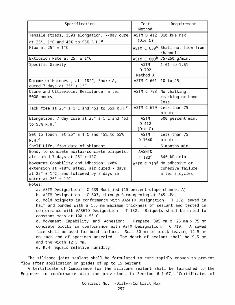
Circuits with Model 500 changeable message signs shall have service equipment enclosures which have main busses and terminal lugs rated for 100 A, minimum, and a No. 2 bare copper ground wire.
Each service shall be provided with up to 2 main circuit breakers which shall disconnect ungrounded service entrance conductors.
A barrier terminal block rated for 60 A, minimum shall be provided in each service equipment enclosure.Circuit breakers used as service disconnect equipment shall have a minimum interrupting capacity of 42 000 A, rms, for
120/240 V(ac) services.
ELECTRIC SERVICE (IRRIGATION)Electric service (irrigation) shall be from the service points to the irrigation controllers (IC) and to the spaces provided in
the irrigation controller enclosure cabinets (CEC) for irrigation controllers as shown on the plans.
10-3.24 NUMBERING ELECTRICAL EQUIPMENTSelf-adhesive numbers (with reflective sheet background) will be State-furnished in conformance with the provisions in
"Materials" of these special provisions.The numbers shall be placed on the equipment where designated by the Engineer.Where new numbers are to be placed on existing or relocated equipment, the existing numbers shall be removed.Numbers shall be applied to a clean surface.Where shown on the plans, equipment numbers shall be placed for all electroliers, sign lighting, and service equipment
enclosures. On service equipment enclosures, the numbers shall be placed on the front door. On electroliers and CCTV poles, the numbers shall be placed on the side nearest the roadway facing approaching traffic at a height up to 2.5 -m above the base plate.
Numbers for illuminated signs mounted on overcrossings or for soffit luminaires shall be placed on the nearest adjacent bent or abutment at approximately the same station as the sign or soffit luminaire. Where no bent or abutment exists near the sign or soffit luminaire, the number shall be placed on the underside of the structure adjacent to the sign or soffit luminaire. Arrangement of numbers shall be the same as those used for electroliers.
Numbers for overhead sign bridges shall be placed on both posts.
10-3.25 CLOSED CIRCUIT TELEVISION (CCTV) CABINETSThe CCTV (Type 334) cabinets shall conform to the provisions in Section 86-3.03, "Model 170 and Model 2070
Controller Assemblies," of the Standard Specifications and these special provisions.Police panels will not be required.Prior to shipping to the project site, each CCTV cabinet shall be submitted to the Transportation Laboratory for
acceptance testing. The costs of transportation to and from the Laboratory shall be at the Contractor's expense.Foundations for Type 1 housing shall conform to the details in the plans for Model 332 and 334 cabinets.The Engineer shall be notified when each CCTV cabinet is ready for the functional test. The functional test will be
conducted by State forces.Terminal blocks shall conform to the requirements in Chapter 6, Section 5, Subsection 6.5.3, "Terminal Blocks,"
Paragraph 5.3.1 of the TSCES, except that the screw size shall be 8-32.Over voltage protection shall be provided for the power distribution assembly and shall contain as a minimum, a surge
arrestor, which shall reduce the effect of power line voltage transients and be rated as follows:
Recurrent Peak Voltage 184 VEnergy Rating (Minimum) 20 J
Power Dissipation, Average 0.85 WPeak Current for pulses less than 7 microseconds 1250 A
Stand-by Current for 60 Hz Sinusoidal 1 mA or less
The thermostatically controlled fan shall provide 4.25 cubic meter per minute of ventilation. The fan shall be activated when the temperature inside the cabinet exceeds 24 degrees Centigrade and shut off when the temperature is less than 18 degrees Centigrade.
Door locks for the CCTV cabinets shall be a removable-core mortise cam cylinder door lock that receives the State's lock core. The State's lock core is a "Best" construction core. Keys shall be removable from the locks in the locked position only. Door locks shall be installed in conformance with the manufacturer's written instructions and recommendations. Two keys for each door lock shall be delivered to the Engineer.
Contract No. «Dist»-«Contract_No»300

10-3.26 STATE-FURNISHED CONTROLLER ASSEMBLIESThe Model 170 controller assemblies, including controller unit, completely wired controller cabinet and inductive loop
detector sensor units, but without anchor bolts, will be State-furnished as provided under "Materials" of these special provisions.
The Contractor shall construct each controller cabinet foundation as shown on the plans for Model 332 and 334 cabinets (including furnishing and installing anchor bolts), shall install the controller cabinet on the foundation, and shall make field wiring connections to the terminal blocks in the controller cabinet.
Contract No. «Dist»-«Contract_No»301

A listing of field conductor terminations, in each State-furnished controller cabinet, will be furnished free of charge to the Contractor at the site of the work.
State forces will maintain controller assemblies. The Contractor's responsibility for controller assemblies shall be limited to conforming to the provisions in Section 6-1.02, "State-Furnished Materials," of the Standard Specifications.
10-3.27 TELEPHONE DEMARCATION CABINETDuplex convenience receptacles shall have ground-fault circuit interruption as defined by the Code. Circuit interruption
shall occur on 6 mA of ground-fault current and shall not occur on less than 4 mA.A listing of field conductor terminations, in each telephone demarcation cabinet, will be furnished free of charge to the
Contractor at the site of the work.
10-3.28 IRRIGATION CONTROLLER ENCLOSURE CABINETIrrigation controller enclosure cabinets (CEC) shall be constructed and the equipment within the cabinets shall be
installed in conformance with the details shown on the plans, the provisions in the Standard Specifications, and these special provisions.
Irrigation controller enclosure cabinets shall be of metal construction conforming to the details for empty Type P signal cabinets shown on Standard Plans ES-3A and ES-3C, except that the fluorescent interior light, police panels, and shelves shall not be provided, unless otherwise shown on the plans. Cabinets shall be provided with cross ventilation, roof ventilation or a combination of both. The anchorage arrangement shall be inside the cabinet as shown on the plans. Dimensions of the cabinet shall be suitable for the equipment to be installed as shown on the plans and specified in these special provisions.
Irrigation controller enclosure cabinets shall be fabricated in conformance with the provisions in Section 86-3.04A, "Cabinet Construction," of the Standard Specifications.
Irrigation controller enclosure cabinets shall be fabricated of stainless steel.Irrigation controller enclosure cabinet doors shall not be furnished with integral door locks. Irrigation controller
enclosure cabinet door handles shall have provisions for padlocking in the latched position. Padlocks will be State-furnished as provided under "Materials" of these special provisions.
The plywood mounting panel shall be 19-mm exterior AC grade veneer plywood. The panel shall be painted with one application of an exterior, latex based, wood primer and 2 applications of an exterior, vinyl acrylic enamel, white in color. The plywood panel shall be painted on all sides and edges prior to installation of the panel in the cabinet and equipment on the panel.
Inside of the doors shall have provisions for storage of the irrigation plans.Duplex convenience receptacles shall have ground-fault circuit interruption as defined by the Code. Circuit interruption
shall occur on 6 mA of ground-fault current and shall not occur on less than 4 mA. Receptacles shall be installed in a weatherproof housing with rainproof lift covers.
Solid-state automatic shut-off rain sensor units shall be installed for the irrigation controller enclosure cabinets. Rain sensor units shall automatically interrupt the master remote control valves when approximately 3 mm of rain has fallen. The irrigation system shall automatically be enabled again when the accumulated rainfall evaporates from the rain sensor unit collection cup. Rain sensor units shall be rated 24 V (ac) to 30 V (ac). Static charge protection shall be included to protect against lightning damage.
Equipment, except for field wiring, shall be installed in the cabinet in a shop prior to field installation.At the option of the Contractor, irrigation controller enclosure cabinets may be Rain Bird SB-36SS, double door front
entry enclosure and Rain Bird SB-24SS front entry enclosures.Arrangements have been made to insure that any successful bidder can obtain the Rain Bird enclosures from United
Green Tech, formerly Pacific Technical Services, 23372 South Pointe Drive, Suite B, Laguna Hills, California, 92653, telephone (949) 837-4737.
The quoted prices and equipment (when purchased with the Remote Irrigation Control System (RICS) irrigation controllers described in "Electric Automatic Irrigation Components" elsewhere in these special provisions) are as follows:
Contract No. «Dist»-«Contract_No»302

EQUIPMENT DESCRIPTION TOTAL QUANTITYINCLUDED IN THIS
PRICE
QUOTED PRICEFOR TOTAL QUANTITY
SALES TAX EXTENDED PRICE FOR
TOTAL QUANTITY
Rain Bird SB-36SS, double door front entry enclosure 3 $3,930.00 $304.50 $4,234.50Rain Bird SB-24SS front entry enclosures 3 $2,820.00 $218.50 $3038.50
Prices are guaranteed by United Green Tech, formerly Pacific Technical Services for one year from the date of the quote, January 12, 2001.
10-3.29 VEHICLE SIGNAL FACES AND SIGNAL HEADSType SV-1-T mountings with 5 sections and SV-2-TD mountings shall be bolted to the standard through the upper pipe
fitting in the same manner shown for bolting the terminal compartment.
10-3.30 LIGHT EMITTING DIODE SIGNAL MODULETraffic signal faces with 300-mm sections, 200-mm sections or arrow sections shall use light emitting diode (LED)
signal modules as the light source in conformance with these special provisions.
GENERALType 1 LED signal modules shall be installed in the doorframes of standard traffic signal housings. Lamp sockets,
reflectors, reflector holders and lenses used with incandescent lamps shall not be used when Type 1 LED signal modules are installed.
LED signal modules, including green, yellow, red, circular balls and arrow indications shall be from the same manufacturer, and each size shall be the same model.
Type 1 LED signal modules shall be sealed units with two color-coded conductors for power connection, a printed circuit board, a power supply, a lens and a gasket. LED signal modules shall be weatherproof after installation and connection. Circuit boards and power supplies shall be contained inside Type 1 LED signal modules. Circuit boards shall conform to the requirements in Chapter 1, Section 6 of the "Transportation Electrical Equipment Specifications," (TEES) published by the Department.
Conductors for Type 1 LED signal modules shall be one meter in length with quick disconnect terminals attached, and shall conform to the provisions in Section 86-4.01C, "Electrical Components," of the Standard Specifications.
Lenses of Type 1 LED signal modules shall be integral to the units, shall be convex with a smooth outer surface and shall be made of ultraviolet (UV) stabilized plastic or glass. The lenses shall be capable of withstanding ultraviolet exposure from direct sunlight for a minimum period of 36 months without exhibiting evidence of deterioration.
Type 1 LED signal modules shall be sealed in doorframes with one-piece ethylene propylene rubber (EPDM) gaskets.LEDs used in signal modules shall be of Aluminum Indium Gallium Phosphide (AlInGaP) technology for red and yellow
indications and of Gallium Nitride (GaN) technology for green indications. LEDs shall be the ultra bright type rated for 100,000 hours of continuous operation from -40˚C to +74˚C.
Individual LEDs shall be wired so that a total failure of one LED will result in the loss of not more than 5 percent of the signal module light output. Failure of an individual LED in a string shall not result in the loss of the entire string or any other indication.
Maximum power consumption requirements for LED signal modules shall be as follows:
LED Signal Module
Power Consumption in WattsRed Yellow Green
25°C 74°C 25°C 74°C 25°C 74°C300 mm circular 11 17 22 25 12 12200 mm circular 8 13 13 16 10 10300 mm arrow 9 12 10 12 13 13
Contract No. «Dist»-«Contract_No»303
PHYSICAL AND MECHANICAL REQUIREMENTSInstallation of LED signal modules shall only require the removal of the optical unit components such as the lens, lamp
module, gaskets and reflector. LED signal modules shall be weather tight, fit securely to the housing and connect directly to electrical wiring.
Arrow modules shall conform to the requirements in Section 9.01 of the Institute of Transportation Engineers (ITE) Publication: Equipment and Materials Standards, "Vehicle Traffic Control Signal Heads" for arrow indications. LEDs shall be spread evenly across the illuminated portion of the arrow area.
LED Signal Module LensThe LED signal module shall be capable of replacing the optical unit. The lens may be tinted or may use transparent
film or materials with similar characteristics to enhance "ON/OFF" contrasts. The use of tinting or other materials to enhance "ON/OFF" contrast shall not affect chromaticity and shall be uniform across the face of the lens.
If a polymeric lens is used, a surface coating or chemical surface treatment shall be used to provide front surface abrasion resistance.
Environmental Requirements
LED signal modules shall be rated for use in the operating temperature range of -40˚C to +74˚C.LED signal modules shall be protected against dust and moisture intrusion in conformance with the requirements in
NEMA Standard 250-1991 for Type 4 enclosures to protect internal components.
ConstructionLED signal modules shall be single, self-contained devices, not requiring on-site assembly for installation into existing
traffic signal housings. The power supply for LED signal modules shall be integral to the module.Assembly and manufacturing processes for LED signal modules shall be designed to assure all internal components will
be adequately supported to withstand mechanical shock and vibration from high winds and other sources.
MaterialsMaterials used for lenses and LED signal modules shall conform to the requirements in ASTM Specifications for the
materials.Enclosures containing the power supply or electronic components of LED signal modules shall be made of UL94VO
flame-retardant materials. Lenses of LED signal modules are excluded from this requirement.
Module IdentificationLED signal modules shall have the manufacturer's name, trademark, model number, serial number, lot number, month
and year of manufacture, and required operating characteristics permanently marked on the back of the module. Required operating characteristics shall include rated voltage, power consumption and volt-ampere (VA).
Type 1 LED signal modules shall have prominent and permanent vertical markings for correct indexing and orientation within the signal housings. Markings shall consist of an up arrow or the word "UP" or "TOP."
Contract No. «Dist»-«Contract_No»304

PHOTOMETRIC REQUIREMENTS
Initial luminous intensity values for LED signal modules, operating at 25˚C, shall meet or exceed the following minimum values:
Circular Indications (in cd)200 mm 300 mm
Angle (v,h) Red Yellow Green Red Yellow Green2.5, ±2.5 157 314 314 399 798 7982.5, ±7.5 114 228 228 295 589 5892.5, ±12.5 67 133 133 166 333 3332.5, ±17.5 29 57 57 90 181 1817.5, ±2.5 119 238 238 266 532 5327.5, ±7.5 105 209 209 238 475 4757.5, ±12.5 76 152 152 171 342 3427.5, ±17.5 48 95 95 105 209 2097.5, ±22.5 21 43 43 45 90 907.5, ±27.5 12 24 24 19 38 3812.5, ±2.5 43 86 86 59 119 11912.5, ±7.5 38 76 76 57 114 11412.5, ±12.5 33 67 67 52 105 10512.5, ±17.5 24 48 48 40 81 8112.5, ±22.5 14 29 29 26 52 5212.5, ±27.5 10 19 19 19 38 3817.5, ±2.5 19 38 38 26 52 5217.5, ±7.5 17 33 33 26 52 5217.5, ±12.5 12 24 24 26 52 5217.5, ±17.5 10 19 19 26 52 5217.5, ±22.5 7 14 14 24 48 4817.5, ±27.5 5 10 10 19 38 38
Arrow Indications (in cd/m2)Red Yellow Green
Arrow Indication 5500 11 000 11 000
Contract No. «Dist»-«Contract_No»305

LED signal modules shall meet or exceed the following minimum illumination values for a minimum period of 36 months, based on normal use in traffic signal operation over an operating temperature range of -40˚C to +74˚C. In addition, yellow LED signal modules shall meet or exceed the following minimum illumination values for a minimum period of 36 months, based on normal use in traffic signal operation at 25˚C:
Circular Indications (in cd)200 mm 300 mm
Angle (v,h) Red Yellow Green Red Yellow Green2.5, ±2.5 133 267 267 339 678 6782.5, ±7.5 97 194 194 251 501 5012.5, ±12.5 57 113 113 141 283 2832.5, ±17.5 25 48 48 77 154 1547.5, ±2.5 101 202 202 226 452 4527.5, ±7.5 89 178 178 202 404 4047.5, ±12.5 65 129 129 145 291 2917.5, ±17.5 41 81 81 89 178 1787.5, ±22.5 18 37 37 38 77 777.5, ±27.5 10 20 20 16 32 3212.5, ±2.5 37 73 73 50 101 10112.5, ±7.5 32 65 65 48 97 9712.5, ±12.5 28 57 57 44 89 8912.5, ±17.5 20 41 41 34 69 6912.5, ±22.5 12 25 25 22 44 4412.5, ±27.5 9 16 16 16 32 3217.5, ±2.5 16 32 32 22 44 4417.5, ±7.5 14 28 28 22 44 4417.5, ±12.5 10 20 20 22 44 4417.5, ±17.5 9 16 16 22 44 4417.5, ±22.5 6 12 12 20 41 4117.5, ±27.5 4 9 9 16 32 32
Arrow Indications (in cd/m2)Red Yellow Green
Arrow Indication 5 500 11 000 11 000
Measured chromaticity coordinates of LED signal modules shall conform to the chromaticity requirements of the following table, for a minimum period of 36 months, over an operating temperature range of -40˚C to +74˚C.
Chromaticity StandardsRed Y: not greater than 0.308, or less than 0.998 -x
Yellow Y: not less than 0.411, nor less than 0.995 - x, nor less than 0.452
Green Y: not less than 0.506 - 0.519x, nor less than 0.150 + 1.068x, nor more than 0.730 - x
LED signal modules tested or submitted for testing shall be representative of typical production units. Circular LED modules shall be tested in conformance with California Test 604. Optical testing shall be performed with LED signal modules mounted in standard traffic signal sections without visors or hoods attached to the signal sections.
LEDs for arrow indications shall be spread evenly across the illuminated portion of the arrow area. Arrow LED signal modules shall be tested in conformance with California Test 3001. Optical testing shall be performed with LED signal modules mounted in standard traffic signal sections without visors or hoods attached to the signal sections. LED arrow signal section indication shall provide minimum initial luminous intensity as listed herein. Measurements shall be performed at the rated operating voltage of 120 V (ac).
Contract No. «Dist»-«Contract_No»306

ELECTRICALMaximum power consumption requirements for LED signal modules shall not exceed those listed in "General." LED
signal modules shall operate at a frequency of 60 Hz ± 3 Hz over a voltage range from 95 V (ac) to 135 V (ac) without perceptible flicker. Fluctuations of line voltage shall have no visible effect on luminous intensity of the indications. Rated voltage for all measurements shall be 120 V (ac).
Wiring and terminal blocks shall conform to the requirements of Section 13.02 of the ITE Publication: Equipment and Material Standards, (Vehicle Traffic Control Signal Heads). Two secured, color coded, 1 meter long, 600 V, 20 AWG minimum, jacketed wires, conforming to the National Electronic Code, rated for service at +105˚C, shall be provided for electrical connection for each Type 1 LED signal module.
LED signal module on-board circuitry shall include voltage surge protection to withstand high repetition noise transients in conformance with the requirements in Section 2.1.6 of NEMA Standard TS2-1992.
LED signal modules shall be operationally compatible with currently used controller assemblies including solid state load switches, flashers and conflict monitors. When a current of 20 milliamperes (ac) or less is applied to the unit, the voltage read across the two leads shall be 15 V (ac) or less.
LED signal modules and associated on-board circuitry shall conform to the requirements in Federal Communications Commission (FCC) Title 47, SubPart B, Section 15 regulations concerning the emission of electronic noise.
LED signal modules shall provide a power factor of 0.90 or greater.Total harmonic distortion from current and voltage induced into an alternating current power line by LED signal
modules shall not exceed 20 percent at an operating temperature of 25˚C.
QUALITY CONTROL PROGRAMLED signal modules shall be manufactured in conformance with a vendor quality control (QC) program. The QC
program shall include two types of testing: (1) design qualification and (2) production quality. Production quality testing shall include statistically controlled routine tests to ensure minimum performance levels of LED signal modules built to meet these specifications.
Documentation of the QC process and test results shall be kept on file for a minimum period of seven years.LED signal module designs not satisfying design qualification testing and the production quality testing performance
requirements specified herein shall not be labeled, advertised or sold as conforming to these specifications.Identification of components and subassemblies of LED signal modules, which may affect reliability and performance,
shall be traceable to the original manufacturers.
Design Qualification TestingDesign qualification testing (DQT) shall be performed by the manufacturer or an independent testing lab hired by the
manufacturer on new LED signal module designs, and on existing designs when a major design change has been implemented. Failure to conform to the requirements of any design qualification test shall be cause for rejection.
A major design change is defined as a design change, electrical or physical, which changes any of the performance characteristics of the LED signal module, results in a different circuit configuration for the power supply, or changes the layout of the individual LEDs in the signal module.
Two LED modules for each design shall be used for DQT. The two LED signal modules shall be selected at random. These signal modules shall be submitted to the Transportation Laboratory after the DQT is complete. Testing data shall be submitted with the modules to the Transportation Laboratory for verification of DQT data.
LED signal modules shall be energized for a minimum of 24 hours, at 100 percent on-time duty cycle, at a temperature of 74˚C before performing any DQT.
After burn-in, LED signal modules shall be tested for rated initial luminous intensity in conformance with the provisions in "Photometric Requirements." Before measurement, LED signal modules shall be energized at rated voltage, with 100 percent on-time duty cycle, for a time period of 30 minutes. Photometrics, luminous intensity and color measurements for yellow LED signal modules shall be taken immediately after the modules are energized. The ambient temperature for these measurements shall be 25˚C. Test results for this testing shall record the current, voltage, total harmonic distortion (THD) and power factor (PF) associated with each measurement.
LED signal modules shall be tested by measuring for chromaticity (color) in conformance with the provisions in "Photometric Requirements." A spectra radiometer shall be used for this measurement. The ambient temperature for this measurement shall be 25˚C.
LED signal modules shall be tested by measuring the current flow in amperes. The measured current values shall be used for quality comparison of production quality assurance on production modules.
LED signal modules shall be tested by measuring the power factor. A commercially available power factor meter may be used to perform this measurement.
Contract No. «Dist»-«Contract_No»307

LED signal modules shall be tested by measuring the total harmonic distortion. A commercially available total harmonic distortion meter may be used to perform this measurement.
LED signal modules shall be tested in conformance with the provisions in "Electrical," with reference to Class A emission limits referenced in Federal Communications Commission (FCC) Title 47, SubPart B, Section 15.
LED signal modules shall be tested for compatibility with the controller unit, conflict monitor and load switch. Each signal module shall be connected to the output of a standard load switch connected to an alternating current voltage supply between the values of 95 and 135 V (ac) with the input to the load switch in the "OFF" position. The alternating current voltage developed across each LED signal module so connected shall not exceed 15 V rms as the input alternating current voltage is varied from 95 V (ac) rms to 135 V (ac) rms.
LED signal modules shall be tested for transient immunity in conformance with the provisions in "Electrical," and conforming to the procedure described in NEMA Standard TS2-1992.
Mechanical vibration testing shall be performed on LED signal modules in conformance with the requirements in MIL-STD-883, Test Method 2007, using three 4-minute cycles along each x, y, and z axis, at a force of 2.5 Gs, with a frequency sweep from 2 Hz to 120 Hz. The loosening of the lens, internal components, or other physical damage shall be cause for rejection.
Temperature cycling shall be performed on LED signal modules in conformance with the requirements of MIL-STD-883, Test Method 1010. The temperature range shall conform to the provisions in "Environmental Requirements." A minimum of 20 cycles shall be performed with a 30 minute transfer time between temperature extremes and a 30 minute dwell time at each temperature. LED signal module under test shall be non-operating. Failure of LED signal modules to function properly or evidence of cracking of LED signal module lenses or housings after temperature cycling shall be cause for rejection.
Moisture resistance testing shall be performed on LED signal modules in conformance with the requirements in NEMA Standard 250-1991 for Type 4 enclosures. Evidence of internal moisture after testing shall be cause for rejection.
Production Quality TestingProduction quality testing shall be performed on each LED signal module prior to shipment. Failure to conform to the
requirements of any production quality test shall be cause for rejection. The manufacturer shall retain test results for seven years for warranty purposes.
LED signal modules shall be tested for rated initial intensity after burn-in. The burn-in period shall consist of signal modules being energized at rated voltage for a 30 minute stabilization period before the measurements are made. A single point measurement with a correlation to the minimum initial luminous intensity requirements of "Photometric Requirements" for circular modules may be used. The ambient temperature for this measurement shall be +25°C.
LED signal modules shall be tested for luminous intensity requirements in "Photometric Requirements."LED signal modules shall be tested for required power factor after burn-in. LED signal modules shall be tested by measuring current flow in amperes after burn-in. The measured current values
shall be compared against current values resulting from design qualification measurements under "Design Qualification Testing." The current flow shall not exceed the rated value. The measured ampere values with rated voltage shall be recorded as volt-ampere (VA) on the product labels.
LED signal modules shall be visually inspected for any exterior physical damage or assembly anomalies. The surface of the lens shall be free of scratches, abrasions, cracks, chips, discoloration, or other defects. Any such defects shall be cause for rejection.
CERTIFICATE OF COMPLIANCEThe Contractor shall provide the Engineer a Certificate of Compliance from the manufacturer, in conformance with the
provisions of Section 6-1.07, "Certificates of Compliance," of the Standard Specifications. The certificate shall certify that the LED signal modules comply with the requirements of these specifications. The certificate shall also include a copy of all applicable test reports on the LED signal modules.
QUALITY ASSURANCE TESTING (RANDOM SAMPLE TESTING)The State may perform random sample testing on all shipments. Random sample testing will be completed within
30 days after delivery to the Transportation Laboratory. Circular LED signal modules shall be tested in conformance with California Test 604 and these special provisions. Arrow signal modules shall be tested in conformance with California Test 3001 and these special provisions. Optical testing shall be performed with the module mounted in a standard traffic signal section, but without a visor or hood attached to the section or housing. The number of modules tested shall be determined by the quantity of each model in the shipment. The sample size shall conform to ANSI/ASQC Z1.4. The Transportation Laboratory shall determine the sampling parameters to be used for the random sample testing. All parameters of the specification may be tested on the modules. Acceptance or rejection of the shipment shall conform to ANSI/ASQC Z1.4 for random sampled shipments.
Contract No. «Dist»-«Contract_No»308

WARRANTYThe manufacturer shall provide a written warranty against defects in materials and workmanship for LED signal modules
for a period of 36 months after installation of LED signal modules. Replacement LED signal modules shall be provided within 5 days after receipt of failed LED signal modules at no cost to the State, except the cost of shipping the failed modules. All warranty documentation shall be given to the Engineer prior to installation. Replacement LED signal modules shall be delivered to Caltrans Maintenance Electrical Shop at 7181 Opportunity Road, San Diego, CA 92111.
10-3.31 LIGHT EMITTING DIODE PEDESTRIAN SIGNAL FACE MODULESLight emitting diode (LED) pedestrian signal face (PSF) modules shall be installed in standard Type A pedestrian signal
housing, "UPRAISED HAND" and "WALKING PERSON," and shall use light emitting diodes as the light source as shown on the plans and in conformance with these special provisions.
GENERALPSF modules shall be designed to mount in standard Type A housings. PSF modules shall be designed to mount behind
or replace face plates of standard Type A housings in conformance with the requirements of the Institute of Transportation Engineers (ITE) Standards: "Pedestrian Traffic Control Signal Indications" and the "Manual on Uniform Traffic Control Devices" (MUTCD). Where existing Type A pedestrian signal faces contain both incandescent and LED light sources, both light sources shall be removed and replaced by a new LED pedestrian signal face module in conformance with these special provisions.
PSF modules used on this project shall be from a single manufacturer.Circuit boards and power supplies shall be contained inside the LED modules. Circuit boards shall conform to the
requirements in Chapter 1, Section 6 of the "Transportation Electrical Equipment Specifications," (TEES) published by the Department.
PSF modules shall fit into existing Type A housings and shall not require a specific mounting orientation and shall not vary in light output, pattern or visibility for any mounting orientation.
LEDs for "UPRAISED HAND" symbols shall utilize Aluminum Indium Gallium Phosphide (AlInGaP) technology and shall be the ultra bright type rated for 100,000 hours of continuous operation from -40˚C to +74˚C.
Individual LEDs shall be wired so that a total failure of one LED will result in the loss of not more than 5 percent of the PSF module light output. Failure of an individual LED in a string shall not result in the loss of the entire string or any other indication.
PSF modules tested and those submitted for testing shall be representative of typical production units. PSF modules shall be tested in conformance with California Test 610 and as specified herein.
Luminance Requirements
Luminance of the "UPRAISED HAND" symbol shall be 3750 cd/m2 minimum. Color of "UPRAISED HAND" shall be Portland orange conforming to the requirements of the ITE Standards: "Pedestrian Traffic Control Signal Indications" and the MUTCD.
Luminance of the "WALKING PERSON" symbol shall be 5300 cd/m2 minimum. Color of "WALKING PERSON" shall be white (Luminous Tubing) conforming to the requirements of the ITE Standards: "Pedestrian Traffic Control Signal Indications" and the MUTCD.
Height and width of each symbol shall not be less than 250 mm and 165 mm respectively. Uniformity ratio of illuminated symbols shall not exceed 4 to 1 between the highest luminance area and the lowest luminance area.
PSF modules shall be rated for a minimum useful life of 36 months and shall maintain at least 85 percent of 3750 cd/m2
for "UPRAISED HAND" symbols and 85 percent of 5300 cd/m2 for "WALKING PERSON" symbols after 36 months of continuous use in traffic signal operation over a temperature range of -40˚C to +74˚C.
Physical and Mechanical RequirementsPSF modules shall be designed as retrofit replacement for existing optical units of signal lamps, or existing pedestrian
signal faces with both LED and incandescent light sources, and shall not require special tools for installation. PSF modules shall fit into pedestrian signal section housings built in conformance with the ITE Publication: Equipment and Materials Standards, Chapter 2 "Vehicle Traffic Control Signal Heads" (VTCSH) without modification to the housing.
Environmental Requirements
PSF modules shall be rated for use in the operating temperature range of -40˚C to +74˚C.
Contract No. «Dist»-«Contract_No»309

ConstructionPSF modules shall be single, self-contained devices, not requiring on-site assembly for installation into standard Type A
housings. Power supplies for PSF modules shall be integral to the modules.Assembly and manufacturing processes for PSF modules shall be designed to assure all internal components will be
adequately supported to withstand mechanical shock and vibration from high winds and other sources.
MaterialsMaterial used for PSF modules shall conform to the requirements in ASTM specifications for the materials.Enclosures containing either the power supply or electronic components of the PSF module shall be made of UL94VO
flame-retardant materials.
Module IdentificationPSF modules shall have the manufacturer's name, trademark, model number, serial number, lot number, month and year
of manufacture, and required operating characteristics permanently marked on the back of the module. Required operating characteristics shall include rated voltage, power consumption and volt-ampere (VA).
Type A pedestrian signal face, combination "UPRAISED HAND"/"WALKING PERSON" section, housings without the reflectors shall be used for PSF modules.
PHOTOMETRIC REQUIREMENTSPSF modules shall maintain at least 85 percent of the following luminous intensity values over 36 months of continuous
use in signal operation over the temperature range of -40˚C to +74˚C. In addition, PSF modules shall meet or exceed the following luminous intensity values upon initial testing at 25˚C.
PSF module Luminous IntensityUPRAISED HAND 3750 cd/m2
WALKING PERSON 5300 cd/m2
The measured chromaticity coordinates of PSF modules shall conform to the requirements for chromaticity in Section 5.3.2.1 and Figure C of the VTCSH standards.
ELECTRICALPSF module power consumption shall not exceed the following maximum values:
PSF modulePower Consumption
@ 25ºCPower Consumption
@ 74ºCUPRAISED HAND 10.0 W 12.0 W
WALKING PERSON 12.0 W 15.0 W
PSF modules shall operate at a frequency of 60 Hz ± 3 Hz over a voltage range from 95 V (ac) to 135 V (ac) without perceptible flicker. Fluctuations of line voltage shall have no visible effect on the luminous intensity of the indications. Rated voltage for all measurements shall be 120 V (ac).
PSF module on-board circuitry shall include voltage surge protection to withstand high-repetition noise transients in conformance with the requirements in Section 2.1.6 of NEMA Standard TS2-1992.
Wiring and terminal blocks shall conform to the requirements of Section 13.02 of the ITE Publication: Equipment and Material Standards, "Vehicle Traffic Control Signal Heads."
PSF modules shall be operationally compatible with currently used controller assemblies including solid state load switches, flashers and conflict monitors. When a current of 20 milliamperes (ac) or less is applied to the unit, the voltage read across the two leads shall be 15 V (ac) or less.
PSF modules and associated on-board circuitry shall conform to the requirements in Federal Communications Commission (FCC) Title 47, SubPart B, Section 15 regulations concerning the emission of electronic noise.
PSF modules shall provide a power factor of 0.90 or greater.Total harmonic distortion from current and voltage induced into an alternating current power line by PSF modules shall
not exceed 20 percent at an operating temperature of 25°C.
Contract No. «Dist»-«Contract_No»310

QUALITY CONTROL PROGRAMPSF modules shall be manufactured in conformance with a vendor quality control (QC) program. The QC program shall
include two types of testing: (1) design qualification and (2) production quality. Production quality testing shall include statistically controlled routine tests to ensure minimum performance levels of PSF modules built to meet these specifications.
Documentation of the QC process and test results shall be kept on file for a minimum period of seven years.PSF module designs not satisfying design qualification testing and the production quality testing performance
requirements specified herein shall not be labeled, advertised or sold as conforming to these specifications.Identification of components and subassemblies of PSF modules, which may affect reliability and performance, shall be
traceable to the original manufacturers.
Design Qualification TestingDesign qualification testing (DQT) shall be performed by the manufacturer or an independent testing lab hired by the
manufacturer on new PSF module designs, and on existing designs when a major design change has been implemented. Failure to conform to the requirements of any design qualification test shall be cause for rejection.
A major design change is defined as a design change, electrical or physical, which changes any of the performance characteristics of the PSF module, results in a different circuit configuration for the power supply, or changes the layout of the individual LEDs in the PSF module.
Two PSF modules for each design shall be used for DQT. The two PSF modules shall be selected at random. These PSF modules shall be submitted to the Transportation Laboratory after the DQT is complete. The testing data shall be submitted with the PSF modules to the Transportation Laboratory for verification of DQT data.
The PSF modules shall be energized for a minimum of 24 hours, at 100 percent on-time duty cycle, at a temperature of 74˚C before performing any DQT.
After burn-in, the PSF modules shall be tested for rated initial luminous intensity in conformance with the provisions in "Photometric Requirements." Before measurement, PSF modules shall be energized at rated voltage, with 100 percent on-time duty cycle, for a time period of 30 minutes. The ambient temperature for these measurements shall be 25˚C. The test results shall include the recorded current, voltage, total harmonic distortion (THD) and power factor (PF) associated with each measurement.
PSF modules shall be tested by measuring for chromaticity (color) in conformance with the provisions in "Photometric Requirements." A spectra radiometer shall be used for these measurements. The ambient temperature for these measurements shall be 25˚C.
PSF modules shall be tested by measuring for current flow in amperes. The measured current values shall be used for comparison of production quality assurance on production modules.
PSF modules shall be tested by measuring for power factor. A commercially available power factor meter may be used to perform this measurement.
PSF modules shall be tested by measuring for total harmonic distortion. A commercially available total harmonic distortion meter may be used to perform this measurement.
PSF modules shall be tested in conformance with the provisions in "Electrical," with reference to Class A emission limits referenced in Federal Communications Commission (FCC) Title 47, SubPart B, Section 15.
PSF modules shall be tested for compatibility with the controller unit, conflict monitor and load switch. Each PSF module shall be connected to the output of a standard load switch connected to an alternating current voltage supply between the values of 95 and 135 V (ac) with the input to the load switch in the "OFF" position. The alternating current voltage developed across each PSF module shall not exceed 10 V rms as the input alternating current voltage is varied from 95 V (ac) rms to 135 V (ac) rms.
PSF modules shall be tested for transient immunity in conformance with the provisions in "Electrical" and conforming to the procedure described in NEMA Standard TS2-1992.
Mechanical vibration testing shall be performed on PSF modules in conformance with the requirements in MIL-STD-883, Test Method 2007, using three 4-minute cycles along each x, y, and z axis, at a force of 2.5 Gs, with a frequency sweep from 2 Hz to 120 Hz. The loosening of the lens, of any internal components, or other physical damage shall be cause for rejection.
Temperature cycling shall be performed on PSF modules in conformance with the requirements of MIL-STD-883, Test Method 1010. The temperature range shall conform to the provisions in "Environmental Requirements." A minimum of 20 cycles shall be performed with a 30 minute transfer time between temperature extremes and a 30 minute dwell time at each temperature. Signal under test shall be non-operating. Failure of PSF modules to function properly or evidence of cracking of PSF module lenses or housings after temperature cycling shall be cause for rejection.
Moisture resistance testing shall be performed on PSF modules in conformance with the requirements in NEMA Standard 250-1991 for Type 4 enclosures. Evidence of internal moisture after testing shall be cause for rejection.
Contract No. «Dist»-«Contract_No»311

Production Quality TestingProduction quality tests shall be performed on each PSF module prior to shipment. Failure to conform to the
requirements of any production quality tests shall be cause for rejection. The manufacturer shall retain test results for seven years for warranty purposes.
PSF modules shall be tested for rated initial intensity after burn-in. The burn-in period shall consist of signal modules being energized at rated voltage for a 30 minute stabilization period before the measurements are made.
PSF modules shall be tested for luminous intensity requirements in "Photometric Requirements."PSF modules shall be tested for required power factor after burn-in. PSF modules shall be tested by measuring current flow in amperes after burn-in. The measured current values shall be
compared against current values resulting from design qualification measurements under "Design Qualification Testing." The current flow shall not exceed the rated value. The measured ampere values with rated voltage shall be recorded as volt-ampere (VA) on the product labels.
PSF modules shall be visually inspected for any exterior physical damage or assembly anomalies. The surface of the lens shall be free of scratches, abrasions, cracks, chips, discoloration, or other defects. Any such defects shall be cause for rejection.
CERTIFICATE OF COMPLIANCEThe Contractor shall provide the Engineer a Certificate of Compliance from the manufacturer, in conformance with the
provisions of Section 6-1.07, "Certificates of Compliance," of the Standard Specifications. The certificate shall certify that the PSF modules comply with the requirements of these specifications. The certificate shall also include a copy of all applicable test reports on the PSF modules.
QUALITY ASSURANCE TESTING (RANDOM SAMPLE TESTING)The State may perform random sample testing on all shipments. Random sample testing will be completed within
30 days after delivery to the Transportation Laboratory. PSF modules shall be tested in conformance with California Test 606 and these special provisions. Optical testing shall be performed with the module mounted in a standard traffic signal section or in a standard Type A pedestrian housing, but without a visor or hood attached to the section or housing. The number of modules tested shall be determined by the quantity of each model in the shipment. The sample size shall conform to ANSI/ASQC Z1.4. The Transportation Laboratory shall determine the sampling parameters to be used for the random sample testing. All parameters of the specification may be tested on the modules. Acceptance or rejection of the shipment shall conform to ANSI/ASQC Z1.4 for random sampled shipments.
WARRANTYThe manufacturer shall provide a written warranty against defects in materials and workmanship for the PSF modules for
a period of 36 months after installation of the PSF modules. Replacement PSF modules shall be provided within 5 days after receipt of failed PSF modules at no cost to the State, except the cost of shipping the failed modules. All warranty documentation shall be given to the Engineer prior to installation. Replacement PSF modules shall be delivered to Caltrans Maintenance Electrical Shop at 7181 Opportunity Road, San Diego, CA 92111.
10-3.32 DETECTORSLoop detector sensor units will be State-furnished in conformance with the provisions in "Materials" of these special
provisions.Loop wire shall be Type 2.Loop detector lead-in cable shall be Type B. Like-numbered detector loops, when shown on the plans, shall be connected to the same detector lead-in cable.Slots shall be filled with elastomeric sealant or hot-melt rubberized asphalt sealant.For Type E detector loops, sides of the slot shall be vertical and the minimum radius of the slot entering and leaving the
circular part of the loop shall be 40 mm. Slot width shall be a maximum of 20 mm.The depth of loop sealant above the top of the uppermost loop wire in the sawed slots shall be 50 mm, minimum.The ends of loop detector lead-in cables terminating at a controller cabinet with double row barrier terminal blocks shall
have crimped and soldered ring terminals, otherwise the ends shall have approximately 19 mm of insulation removed and the exposed wire soldered.
10-3.33 HIGH MAST LIGHTING ASSEMBLYThe high mast lighting assembly shall include the foundation, pole, luminaire lowering device system, and luminaires, as
shown on the plans and in conformance with these special provisions.
Contract No. «Dist»-«Contract_No»312

GENERALInstallation of the lowering device on each pole shall be made under the supervision of a trained representative of the
lowering device manufacturer. Prior to acceptance of the contract, a trained representative of the lowering device manufacturer shall demonstrate that each high mast lighting assembly operates properly. The demonstration shall consist of a minimum of 3 complete cycles of raising and lowering the luminaire ring (complete with luminaires) the full length of the ring's travel, as designed, within one working day, prior to acceptance of the project.
All portions of the high mast lighting assembly shall have a minimum design wind velocity rating of 130 km/h.The lowering device system shall be submitted for inspection and testing. Inspection and testing shall be performed at a
site in California approved by the Engineer. The lowering device system shall be demonstrated at the Contractor's expense. Notification shall be given to the Engineer at least 7 days prior to demonstration.
After the high mast lighting system is in operation, an instructional video tape (VHS), complete written instructions and a demonstration to State Maintenance personnel on the maintenance of the high mast lighting assembly, including leveling of the luminaire ring and the procedures for the safe raising and lowering of the luminaire ring, shall be provided.
Spare parts, part lists and the operating, maintenance and service instructions, packaged with or accompanying the equipment installed on the project, shall be delivered to the Engineer prior to acceptance of the project.
SUBMITTALSSubmittals for the high mast lighting assembly shall conform to the provisions in Section 86–1.04, "Equipment List and
Drawings," of the Standard Specifications and these special provisions. Submittals shall be delivered to the Engineer at least 45 days prior to erection of the high mast lighting assembly. The Engineer shall be allowed 45 days for the review of submittals. Review areas will include structural, welding, electrical and other areas as determined by the Engineer.
A. Descriptive data, design working drawings, erection working drawings (including aiming directions for each luminaire if the luminaire has an asymmetrical light distribution), isolux diagram for each type of luminaire, calculations, and a list of the material used for the high mast lighting assembly shall be submitted to the Engineer. The material list shall be complete with the name of manufacturer, catalog number, size, capacity, finish, pertinent ratings and identification symbols used on the plans or in the special provisions for each unit.
B. Each submittal shall consist of 5 copies.C. Plans and detailed drawings shall be not larger than 559 mm x 864 mm.D. Each separate item submitted shall bear a descriptive title and the State contract number.
Two copies of the submittals shall be forwarded to the Office of Structure Design. The Engineer shall be given a copy of the cover letter or other notification, and date, that the copies were sent to the Office of Structure Design.
INSPECTIONThe high mast light poles will be inspected at the fabrication site. The Engineer shall be notified when materials have
been delivered to the fabrication site. After delivery, the Engineer shall be given at least 10 days notice before fabrication of the light poles commences.
If all or a portion of the high mast poles are fabricated more than 480 air line kilometers from both Sacramento and Los Angeles, additional shop inspection expenses will be sustained by the State. Whereas it is and will be impracticable and extremely difficult to ascertain and determine the actual increase in such expenses, it is agreed that payment to the Contractor for furnishing said High Mast Light Poles will be reduced by $2500 for each fabrication site located more than 480 air line kilometers from both Sacramento and Los Angeles and an additional $2500 ($5000 total) for each fabrication site located more than 4800 air line kilometers from both Sacramento and Los Angeles.
CORROSION RESISTANCECorrosion resistance shall be provided. Methods shall include the following:
A. Avoidance of contact between stainless steel and carbon steel, between different types of stainless steel (including welding material), and between aluminum and ferrous materials.
B. Utilizing continuous welding to eliminate crevices which retain moisture.C. Minimizing welding of stainless steel.D. Use of adequate sections and suitable materials to limit stress related corrosion.
POLEThe pole shall conform to the provisions in Section 86-2.04, "Standards, Steel Pedestals and Posts," of the Standard
Specifications, and these special provisions.
Contract No. «Dist»-«Contract_No»313

The pole shall include shaft, access hole, access hole cover, support plate and anchor base.The shaft shall consist of sections of a round or multisided (16 sides) tapered steel tube with a uniform taper of
approximately 12 mm per meter. Segments of multisided poles shall be convex and shall have a minimum bend radius of 100 mm. The pole shall be hot-dip galvanized after fabrication in conformance with the provisions in Section 75-1.05, "Galvanizing," of the Standard Specifications. After galvanizing, the upper 6 m of the pole shall be finished with a fused coating of electrostatically applied polyester powder paint. Applying polyester powder paint shall be in accordance with the provisions in Section 59, “Painting”, of the Standard Specifications, and these special provisions. The color of polyester powder paint shall be black. Steel used in fabricating the pole shall be a weldable quality steel. No field welding shall be performed in the assembly of the pole.
The pole shall have a reinforced access hole to allow adequate clearance for maintaining and servicing the lowering device. Access hole reinforcement shall provide a bending strength equal to that of the pole without an opening. Other hardware inside the pole shall accommodate the lowering device.
The access door shall be hinged to the pole, open horizontally 180 degrees, and when in the open position shall not interfere with access to the interior of the pole.
The pole shall be erected plumb. The vertical axis of the erected pole shall be within 75 mm of the theoretical vertical axis when measured without the action of sunlight or wind.
The pole shall conform to the requirements of the latest edition and interim revisions of the AASHTO "Standard Specifications for Structural Supports for Highway Signs, Luminaires and Traffic Signals." The maximum allowable wind deflection shall not exceed 14 percent of the pole height.
An embossed aluminum plate shall be attached with rivets to the outside of each pole approximately 50 mm above the access hole. The nameplate shall indicate the name of the pole manufacturer and the height of the pole.
A plastic laminated data sheet shall be secured on the inside of the access hole door. The data sheet shall include the names, addresses and telephone numbers of the manufacturers of the pole, luminaire lowering device and luminaires, and the design parameters, including wind velocity, luminaires (number, wattage, model number, mass, projected area and coefficient of drag), and the mass, projected area and coefficient of drag for the pole top lowering mechanism.
LUMINAIRE LOWERING DEVICEThe luminaire lowering device shall consist of a head frame, a luminaire ring and an internal power drive winch unit.The maximum effective projected area of the total assembly at the top of the pole, exclusive of the luminaires, shall not
exceed 0.5-m2.The mass of the head frame, luminaire ring and cover shall not exceed 340 kg.The head frame shall be hot rolled steel conforming to the requirements in ASTM Designation: A 36. The head frame
shall be attached to the pole by means of a steel slipfitter and secured by a minimum of 4 stainless steel setscrews conforming to the requirements in ASTM Designation: F 880, Type 304. The head frame shall be hot-dip galvanized in conformance with the provisions in Section 75-1.05, "Galvanizing," of the Standard Specifications.
The head frame shall be fitted with at least 6 hoisting cable sheaves, of either galvanized or stainless steel, or aluminum, with a minimum 125-mm pitch diameter. The head frame shall be fitted with electrical power cable sheaves or rollers configured to provide a minimum bending radius as specified by the power cable manufacturer.
The hoisting cable sheaves and electrical power cable sheaves or rollers shall be fitted with suitable keepers to keep the cables in their tracks during pole erection and operation. The sheaves shall be supported by stainless steel shafts and shall be fitted with oil-impregnated sintered bronze bushings or roller bearings.
At least 3 hoisting cables shall be supplied. The cables shall be 4.75-mm, minimum diameter, 7x19 strand, stainless steel aircraft cable, manufactured in conformance with the requirements in Military Specification MIL-8320B.
The head frame shall be provided with a cover designed for that device and securely attached with stainless steel machine screws conforming to the requirements in ASTM Designation: F 593, Type 304 and self-locking nuts conforming to the chemical requirements of ASTM Designation: F 594, Type 304, or a stainless steel clamp band. The shape of the lowering device and cover shall be symmetrical about a vertical axis.
The head frame shall also include a minimum of 3 latches which support the luminaire ring when the lowering device is not in operation. Latching shall be accomplished by the alternate raising and lowering of the luminaire ring by the winch and hoisting assembly. When the luminaire ring is raised to the top of the pole, the ring shall automatically latch and be secure in a locked position. Automatic signaling devices shall be visible to indicate that each latch of the luminaire ring is safely locked in place.
No moving latch parts or springs shall be attached to the head frame. Moving parts of the latching mechanism shall be attached to the luminaire ring and serviceable from the ground.
The luminaire ring shall be fabricated of a 150 mm x 50 mm x 4.55 mm (7-gage), minimum, steel channel or a member of equal strength, with the appropriate number of 50-mm nominal steel tube or pipe mounting arms to accommodate the number of luminaires shown on the plans. The pipe shall conform to the requirements of ASTM Designation: A 53. The
Contract No. «Dist»-«Contract_No»314

ring shall be galvanized in conformance with the provisions in Section 75-1.05, "Galvanizing," of the Standard Specifications.
Roller-contact, spring loaded, centering arms shall be provided which shall center the luminaire ring while ascending and descending the full length of designed travel on the pole. The arm system shall keep the ring concentric with the pole in winds up to 50 km/h. The rollers for the centering arms shall be a water resistant, non-marking material. Axle shafts for arms and rollers shall be stainless steel conforming to the requirements in ASTM Designation: A 276, Type 304. The arms system shall not allow the pole to be inadvertently wedged between the rollers and the luminaire ring. Ultimate support of the luminaire ring shall not be lost by individual or total spring failure.
Provisions shall be made for leveling the luminaire ring while in the lowered position. The luminaire support ring shall be level upon installation and again before completion of the contract.
A prewired 600-V (ac) terminal block in a NEMA Type 3R enclosure and a weatherproof power receptacle shall be mounted on the luminaire ring raceway. When the luminaire ring is lowered to ground level, the receptacle shall enable the luminaires to be energized and tested.
An electrical cable of sufficient length to power the luminaire ring, and with appropriate electrical connections, shall be provided to test the luminaires while in the lowered position. A circuit breaker of the rating shown on the plans and an outlet box shall be provided in the pole base.
Electrical cords shall be attached to a weathertight wiring chamber through weathertight cable connections. The main power cord shall support its full weight when installed. A positive connection between cord segments shall be provided across cord joints to prevent stress on the joints.
Power cable shall be Type SO, rated for 600 V (ac) with the number and size of conductors as required. Luminaire ring distribution cord shall be Type ST with insulation suitable for 105°C. Twist-lock receptacles (male and female) shall be provided and shall be rated at a minimum of 30-A, 480-V (ac).
The internal drive mechanism shall raise or lower the luminaire ring at an approximate speed of 3.3 m per minute. The winch shall be furnished with 6-mm minimum diameter 7x19 strand stainless steel aircraft cable, conforming to the requirements in Military Specification MIL-8320B and of sufficient length to maintain at least 4 wraps around the drum with the luminaire ring in its fully lowered position. Winch cable shall wind uniformly.
The internal power drive winch unit shall include:
A. A heavy duty, totally enclosed, fan cooled, reversible universal type motor, rated at 372 W, minimum, for continuous duty, and provided with overcurrent protection.
B. An adjustable torque limiter with ball or roller bearings on all rotating shafts.C. A remote control reversing switch (labeled "UP" and "DOWN") with minimum 6-m cord.D. Worm-gear driven winch.E. Mounting frame.F. Weatherproof step-down transformer, if necessary, of sufficient power to supply the motor and provided with
overcurrent protection. The transformer, when installed inside the pole, shall be removable without removing other components.
G. Other equipment as necessary.
Internal power drive winch unit components, including transformer, shall be removable through the access hole for repair or replacement.
LUMINAIRESEach luminaire shall consist of a housing, a reflector, a refractor or lens, a ballast, a lamp socket and a lamp.Housings shall be fabricated of aluminum. Housings that are painted shall withstand a 1000-hour salt spray test in
conformance with the requirements in ASTM Designation: B 117. Metal component parts of the housing shall be fabricated from material at least equal in corrosion resistance and finish to the metal in the housing.
The optical system, consisting of the reflector, refractor or lens, lamp socket and lamp, shall be in a sealed chamber. Sealing shall be provided by a gasket between the reflector and refractor or lens, and a gasket between the reflector and lamp socket. The chamber shall have provision for filtered flow of air in and out of the chamber due to lamp heat. Filtering shall be accomplished by either a separate filter or a filtering gasket.
The adjustable component (refractor or reflector) controlling the orientation of the light distribution of asymmetrical luminaires shall be rotatable 360 degrees around a vertical axis.
Each luminaire shall be provided with a slipfitter for mounting on a 50-mm horizontal pipe tenon and shall be adjustable to plus or minus 3 degrees from the axis of the tenon.
The surface of each reflector shall be specular and shall be silvered glass or aluminum protected by either an anodized finish or a silicate film. The reflector shall be shaped so that a minimum of light is reflected through the arc tube of the lamp.
Each refractor or lens shall be made of heat resistant glass.
Contract No. «Dist»-«Contract_No»315

Each lamp socket shall be a porcelain enclosed mogul-multiple type. The shell shall contain integral lamp grips to assure electrical contact under conditions of normal vibrations. The socket shall be rated for 1500-W, 600-V (ac), and 4000-V (ac) pulse (400-W lamp), or 5000-V (ac) pulse (1000-W lamp).
Each luminaire shall enclose a dual fuseholder and 2 fuses rated at 5 A at 480 V (ac). Each fuse shall be the standard midget ferrule type, with "Non-Time-Delay" feature, shall be ETL or UL listed, and shall be 10.3 mm x 38 mm.
The minimum light distribution for each luminaire shall be as shown on the plans.
BALLASTSThe ballast for each high mast luminaire shall consist of components (core and coils, capacitors and starting aid, if
required) mounted within a weatherproof housing which integrally attaches to the top of a luminaire support bracket and lamp support assembly. The ballast shall be readily removable without removing the luminaire from the bracket arm.
Ballasts shall be electrically connected to the optical assembly by means of a prewired quick disconnect.Ballasts shall be the regulator type.
HIGH PRESSURE SODIUM LAMPSHigh pressure sodium lamps shall conform to the provisions in Section 86-6.01B, "High Pressure Sodium Lamps," of the
Standard Specifications and these special provisions. Four hundred-watt high pressure sodium lamps shall have an initial output of 50 000 lumens.
10-3.34 LUMINAIRESLow pressure sodium luminaires shall be the cutoff type.
10-3.35 PHOTOELECTRIC CONTROLSContactors shall be the mechanical armature type.
10-3.36 SIGN LIGHTING FIXTURESWhere new mercury sign lighting fixtures are shown on the plans to be installed, induction lighting fixtures conforming
to the provisions in "Sign Lighting Fixtures-Induction," elsewhere in these special provisions shall be installed instead.
10-3.37 SIGN LIGHTING FIXTURES-INDUCTIONInduction sign lighting fixture shall conform to the provisions for mercury sign lighting fixtures in Section 86-6.05,
"Sign Lighting Fixtures-Mercury," of the Standard Specifications and these special provisions.Each fixture shall consist of a housing with door, a reflector, refractor or a lens, a lamp, a power coupler, a high
frequency (HF) generator and a fuse block.The system lifetime shall be rated at 60 000 hours with a failure rate of less than 10 percent. The system shall be rated at
a nominal wattage of 87 W, 120/240 V(ac). The power factor of the system shall be greater than 90 percent and the total harmonic distortion (THD) shall be less than 10 percent. The system shall be UL approved for wet locations and be FCC Class A listed.
The mounting assembly shall be either cast aluminum, hot-dip galvanized steel plate or steel plate that has been galvanized and finished with a polymeric coating system or the same finish that is used for the housing.
The overall weight of the fixture shall not exceed 20 kg. The manufacturer's brand name, trademark, model number, serial number and date of manufacture shall be located on the packaged assembly and on the outside and inside of the housing.
HOUSINGThe housing shall have a door designed to hold a refractor or lens. The housing door shall be designed to be opened
without the use of tools. The housing and door shall have a powder coat or polyester paint finish of a gray color resembling unfinished fabricated aluminum.
REFLECTORThe reflector may be designed to be removed as a unit that includes the lamp and power coupler.
REFRACTORRefractors (or lenses, if used) shall have smooth exteriors. The lens shall be flat or convex. Convex lenses shall be
made from high-impact resistant, tempered glass.
Contract No. «Dist»-«Contract_No»316

The convex lens shall be so designed or shielded that no fixture luminance is visible when the fixture is approached directly from the rear and the viewing level is the bottom of the fixture. When a shield is used it shall be an integral part of the door casting.
LAMPEach fixture shall be furnished with a 85-W induction lamp. The interior lamp walls shall be fluorescent phosphor
coated. Lamp light output shall be not less than 70 percent at 60 000 hours. Lamps shall have a color-rendering index (CRI) of not less than 80. Lamps shall be rated at a color temperature of 4 000 K. Lamps shall be removable without the use of tools.
POWER COUPLERThe power coupler shall consist of a construction base with antenna, heat sink and electrical connection cable.The power coupler shall be designed so that it can be removed with no more than common hand tools.
HIGH FREQUENCY GENERATORHigh frequency (HF) generators shall provide reliable lamp starting and operation at ambient temperatures down to
-25°C for the rated life of the lamp.The generator output frequency shall be 2.65 MHz +/- 10 percent. The generator radio frequency interference shall meet
the requirements of Part 18 of the FCC.High frequency generators shall be designed for continuous operation at ambient air temperatures from -20°C to 25°C
without reduction in generator life. High frequency generators shall have a design life of not less than 100 000 hours at 55°C.A Certificate of Compliance, conforming to the provisions in Section 6-1.07, "Certificates of Compliance," and a copy of
the high frequency generator test methods and results shall be submitted by the manufacturer with each lot of sign lighting fixtures. The certificate shall state that the high frequency generators meet, in every respect, the above requirements and the generator specifications of the lamp manufacturer.
High frequency generators shall also conform to the following:
A. High frequency generators shall be capable of being easily replaced. All conductor terminals shall be identified as to the component terminal to which they connect.
B. High frequency generators shall be mounted so as to use the portion of the sign lighting fixture upon which they are mounted as a heat sink.
WARRANTYEach fixture shall be warranted by the fixture manufacturer for a period of not less than four years (against mechanical
and electrical defects) and with component warranties as follows: lamps for not less than four years; power couplers for not less than four years; high frequency generators for not less than four years; and housing and door surface finish for not less than four years.
10-3.38 MODEL 500 CHANGEABLE MESSAGE SIGN SYSTEMModel 500 changeable message sign (CMS) systems consist of a Model 500 changeable message sign, a Model 170
controller assembly in a completely wired Type 1 or similar cabinet and the required wiring and auxiliary equipment required to control the CMS shown on the plans and in conformance with these special provisions.
The Model 500 changeable message signs, wiring harness and Model 170 controller assembly including controller unit and completely wired cabinet, but without anchor bolts, will be State-furnished in conformance with the provisions in "Materials" of these special provisions.
Model 500 changeable message sign system components will conform to the requirements in "Specifications for Changeable Message Sign System," issued by the State of California, Department of Transportation, and to the addendums thereto current at the time of project advertising. Model 170 controller assemblies will conform to the requirements in "Traffic Signal Control Equipment Specifications," issued by the State of California, Department of Transportation, and to the addendums thereto current at the time of project advertising.
Attention is directed to "Sign Structures" of these special provisions.The sign assembly shall be installed on the sign structure. The controller cabinet foundation shall be constructed as
shown on the plans for Model 334 cabinets (including furnishing and installing anchor bolts), the controller cabinet shall be installed on the foundation, and the field wiring connections shall be made to the terminal blocks in the sign assembly and in the controller cabinet.
Field conductors No. 12 and smaller shall terminate with spade terminals. Field conductors No. 10 and larger shall terminate in spade or ring terminals.
Contract No. «Dist»-«Contract_No»317

A listing of field conductor terminations, in each State-furnished changeable message sign and controller cabinet, will be furnished free of charge to the Contractor at the site of the work.
The location of the foundation for each controller cabinet will be determined by the Engineer.State forces will maintain the sign assemblies. The Contractor's responsibility shall be limited to conformance with the
provisions in Section 6-1.02, "State-Furnished Materials," of the Standard Specifications.
10-3.39 FIBER OPTIC COMMUNICATION CABLE PLANTFIBER OPTICS GLOSSARY
Breakout.--The cable "breakout" is produced by; (1) removing the jacket just beyond the last tie-wrap point, (2) exposing 1 to 2 meters of the cable buffers, aramid strength yarn and central fiberglass strength member, and (3) cutting the aramid yarn, central strength member and the buffer tubes to expose the individual glass fibers for splicing or connection to the appropriate device.
Connector.--A mechanical device used to align and join two fibers together to provide a means for attaching to and decoupling from a transmitter, receiver, or another fiber (patch panel).
Connectorized.--The termination point of a fiber after connectors have been affixed.
Couplers.--Couplers are devices which mate fiber optic connectors to facilitate the transition of optical light signals from one connector into another. They are normally located within FDFs mounted in panels. They may also be used unmounted, to join two simplex fiber runs.
Fiber Distribution Frame (FDF).--A rack mounted system that consists of a standard equipment rack, fiber routing guides, horizontal jumper troughs and Fiber Distribution Unit (FDU).
The FDF serves as the "home" for the passive fiber optic components from cable breakout, for connection by jumpers, to the electronics.
Fiber Distribution Unit (FDU)--Is an enclosure or rack-mountable unit containing both a patch panel with couplers and a splice tray(s).
F/O.--Fiber optic.
FOIP.--Fiber optic inside plant cable.
FOP.--Fiber optic outside plant cable.
FOTP.--Fiber optic test procedure(s) as defined by EIA/TIA standards.
Jumper.--A short fiber optic cable that has connectors installed on both ends, and is typically used for connection within a FDF.
Light Source.--Portable fiber optic test equipment that, in conjunction with a power meter, is used to perform end-to-end attenuation testing. It contains a stabilized light source operating at the designed wavelength of the system under test.
Link.--A passive section of the system, the ends of which are to be connected to active components. A link may include splices and couplers. For example, a video link may be from a F/O transmitter to a video multiplexer (MUX).
Link Loss Budget.--A calculation of the overall permissable attenuation from the fiber optic transmitter (source) to the fiber optic receiver (detector).
Loose Tube Cable.--Type of cable construction in which fibers are placed in filled buffer tubes to isolate them from outside forces (stress). A flooding compound is applied to the interstitial cable core to prevent water migration and penetration. This type of cable is primarily for outdoor applications.
Optical Time Domain Reflectometer (OTDR).--Fiber optic test equipment (similar in appearance to an oscilloscope) that is used to measure the total amount of power loss between two points and the corresponding distance. It provides a
Contract No. «Dist»-«Contract_No»318
visual and printed display of the relative location of system components such as fiber sections, splices and connectors and the losses that are attributed to each component or defect in the fiber.
Patchcord.--A short jumper used to join two Connector Module Housing (CMH) couplers or a CMH and an active device (electronics).
Pigtail.--Short fiber optic cable that has a connector installed on only one end.
Plenum Cable.--NEC approved cable installed in air plenums (the area between a drop ceiling and the floor above it) without the use of conduit.
Power Meter.--Portable fiber optic test equipment that, in conjunction with a light source, is used to perform end-to-end attenuation testing. It contains a detector that is sensitive to light at the designed wavelength of the system under test. Its display indicates the amount of power injected by the light source that arrives at the receiving end of the link.
Riser Cable.--NEC approved cable installed in a riser (a vertical shaft in a building connecting one floor to another).
Segment.--A section of F/O cable that is not connected to any active device and may or may not have splices per the design.
Splice.--The permanent joining of fiber ends to matching fibers.
Splice Closure.--Normally installed in a splice vault, a splice closure is an environmentally sealed container used to organize and protect splice trays. The container allows splitting or routing of fiber cables from multiple locations.
Splice Module Housing (SMH).--The SMH stores splice trays as well as pigtails and short cable lengths.
Splice Tray.--A container used to organize and protect spliced fibers.
Splice Vault.--A splice vault is used to house splice closures.
Storage Cabinet.--Designed for holding excess cable slack for protection. The storage cabinet allows the user flexibility in equipment location and the ability to pull cable back for resplicing.
Tight Buffered, Non-Breakout Cable (Tight Buffer Cable).--Type of cable construction where each glass fiber is tightly buffered (directly coated) with a protective thermoplastic coating to 900 µm (compared to 250 µm for loose tube fibers). Increased buffering is desirable over loose tube cables because of its resulting ease of handling and connectorization (increased physical flexibility, smaller bend radius requirements), and ability to meet NEC flammability requirements.
FIBER OPTIC OUTSIDE PLANT CABLE
GENERALEach fiber optic outside plant cable (FOP) for this project shall be all dielectric, gel filled or water blocking materials,
duct type, with loose buffer tubes and shall conform to these special provisions. Cables with singlemode fibers shall contain singlemode (SM) dual-window (1310 nm and 1550 nm) fibers in the quantities shown below and on the plans. The optical fibers shall be contained within loose buffer tubes. The loose buffer tubes shall be stranded around an all dielectric central member. Aramid yarn and/or fiberglass shall be used as a primary strength member, and a polyethylene outside jacket shall provide for overall protection.
All fiber optic (F/O) cable on this project shall be from the same manufacturer, who is regularly engaged in the production of this material.
The cable shall comply with all the requirements of the United States Department of Agriculture Rural Electrification Administration specifications REA-PE-90 an as described elsewhere in these Special Provisions.
The quantity of singlemode fibers contained within a cable shall be as shown on the plans.
FIBER CHARACTERISTICSEach optical fiber shall be glass and consist of a doped silica core surrounded by concentric silica cladding. All fibers in
the buffer tube shall be usable fibers, and shall be sufficiently free of surface imperfections and inclusions to meet the optical, mechanical, and environmental requirements of these specifications. The required fiber grade SM shall reflect the maximum individual fiber attenuation, to guarantee the required performance of each and every fiber in the cable.
Contract No. «Dist»-«Contract_No»319

The coating shall be a dual layered, UV cured acrylate. The coating shall be mechanically or chemically strippable without damaging the fiber.
The cable shall comply with the optical and mechanical requirements over an operating temperature range of -40°C to +70°C. The cable shall be tested in accordance with EIA-455-3A (FOTP-3), "Procedure to Measure Temperature Cycling Effects on Optical Fiber, Optical Cable, and Other Passive Fiber Optic Components." The change in attenuation at extreme operational temperatures (-40°C to +70°C) for singlemode fiber shall not be greater than 0.20 dB/km, with 80 percent of the measured values no greater than 0.10 dB/km. The singlemode fiber measurement is made at 1550 nm.
Contract No. «Dist»-«Contract_No»320
For all fibers the attenuation specification shall be a maximum attenuation for each fiber over the entire operating temperature range of the cable.
Singlemode fibers within the finished cable shall meet the requirements in the following table:
Fiber Characteristics Table
Parameters SMType Step IndexCore diameter 8.3 µm (nominal)Cladding diameter 125 µm ±1.0 µmCore to Cladding Offset ≤1.0 µmCoating Diameter 250 µm ±15 µmCladding Non-circularitydefined as: [1-(min. cladding dia ÷max. cladding dia.)]x100
≤2.0%
Proof/Tensile Test 345 MPaAttenuation: @ 850 nm N/A @1310 nm (SM) ≤0.4 dB/km @1,550 nm ≤0.4 dB/kmAttenuation at the Water Peak ≤2.1 dB/km @
1383 ±3 nmBandwidth:
@ 850 nmN/A
@1310 nm (SM)N/A
Chromatic Dispersion:
Zero Dispersion Wavelength1301.5 to 1321.5 nm
Zero Dispersion Slope≤0.092 ps/(nm2*km)
Maximum Dispersion:≤3.3 ps/(nm*km) for 1285 to 1330 nm<18 ps/(nm*km) for 1550 nm
Cut-Off Wavelength
<1250 nm
Numerical Aperture (measured in accordance with EIA-455-47 (FOTP-47))
N/A
Mode Field Diameter(Petermann II)
9.3 ±0.5 µm at 1300 nm10.5 ±1.0 µm at 1550 nm
Contract No. «Dist»-«Contract_No»321

COLOR CODINGOptical fibers shall be distinguishable from others in the same buffer tube by means of color coding according to the
following:
1. Blue (BL)2. Orange (OR)3. Green (GR)4. Brown (BR)5. Slate (SL)6. White (WT)
7. Red (RD) 8. Black (BK) 9. Yellow (YL)10. Violet (VL)11. Rose (RS)12. Aqua (AQ)
The colors shall be targeted in accordance with the Munsell color shades and shall meet EIA/TIA-598 "Color Coding of Fiber Optic Cables."
The color formulation shall be compatible with the fiber coating and the buffer tube filling compound, and be heat stable. It shall not fade or smear or be susceptible to migration and it shall not affect the transmission characteristics of the optical fibers and shall not cause fibers to stick together.
CABLE CONSTRUCTION
General.--The fiber optic cable shall consist of, but not be limited to, the following components:
A. Buffer tubesB. Central memberC. Filler rodsD. StrandingE. Core and cable floodingF. Tensile strength memberG. RipcordH. Outer jacket
Buffer tubes.--Loose buffer tubes shall provide clearance between the fibers and the inside of the tube to allow for expansion without constraining the fiber. The fibers shall be loose or suspended within the tubes and shall not adhere to the inside of the tube. Each buffer tube shall contain 6 or 12 fibers.
The loose buffer tubes shall be extruded from a material having a coefficient of friction sufficiently low to allow free movement of the fibers. The material shall be tough and abrasion resistant to provide mechanical and environmental protection of the fibers, yet designed to permit safe intentional "scoring" and breakout, without damaging or degrading the internal fibers.
Buffer tube filling compound shall be a homogenous hydrocarbon-based gel with anti-oxidant additives and used to prevent water intrusion and migration. The filling compound shall be non-toxic and dermatologically safe to exposed skin. It shall be chemically and mechanically compatible with all cable components, non-nutritive to fungus, non-hygroscopic and electrically non-conductive. The filling compound shall be free from dirt and foreign matter and shall be readily removable with conventional nontoxic solvents.
Buffer tubes shall be stranded around a central member by a method that will prevent stress on the fibers when the cable jacket is placed under strain, such as the reverse oscillation stranding process.
Each buffer tube shall be distinguishable from other buffer tubes in the cable by means of color coding as specified above for fibers.
Central Member.--The central member which functions as an anti-buckling element shall be a glass reinforced plastic rod with similar expansion and contraction characteristics as the optical fibers and buffer tubes. A linear overcoat of low density polyethylene shall be applied to the central member to achieve the optimum diameter to provide the proper spacing between buffer tubes during stranding.
Filler rods.--Fillers may be included in the cable to lend symmetry to the cable cross-section where needed. Filler rods shall be solid medium or high density polyethylene. The diameter of filler rods shall be the same as the outer diameter of the buffer tubes.
Stranding.--Completed buffer tubes shall be stranded around the overcoated central member using stranding methods, lay lengths and positioning such that the cable shall meet mechanical, environmental and performance specifications. A polyester binding shall be applied over the stranded buffer tubes to hold them in place. Binders shall be applied with
Contract No. «Dist»-«Contract_No»322

sufficient tension to secure the buffer tubes to the central member without crushing the buffer tubes. The binders shall be non-hygroscopic, non-wicking (or rendered so by the flooding compound), and dielectric with low shrinkage.
Core and Cable Flooding.--The cable core interstices shall be filled with a polyolefin based compound to prevent water ingress and migration. The flooding compound shall be homogeneous, non-hygroscopic, electrically non-conductive, and non-nutritive to fungus. The compound shall also be nontoxic, dermatologically safe and compatible with all other cable components.
Tensile Strength Member.--Tensile strength shall be provided by high tensile strength aramid yarns and/or fiberglass which shall be helically stranded evenly around the cable core and shall not adhere to other cable components.
Ripcord.--The cable shall contain at least one ripcord under the jacket for easy sheath removal.
Outer jacket.--The jacket shall be free of holes, splits, and blisters and shall be medium or high density polyethylene (PE), or medium density cross-linked polyethylene with minimum nominal jacket thickness of 1000±76 µm. Jacketing material shall be applied directly over the tensile strength members and flooding compound and shall not adhere to the aramid strength material. The polyethylene shall contain carbon black to provide ultraviolet light protection and shall not promote the growth of fungus.
The jacket or sheath shall have clear, distinctive and permanent markings showing the manufacturer's name, the words "Optical Cable", the number of fibers, "SM", year of manufacture, and sequential measurement markings every meter. The actual length of the cable shall be within -0/+1 percent of the length marking. The marking shall be in a contrasting color to the cable jacket. The height of the marking shall be approximately 2.5 mm.
GENERAL CABLE PERFORMANCE SPECIFICATIONSThe F/O cable shall withstand water penetration when tested with a one meter static head or equivalent continuous
pressure applied at one end of a one meter length of filled cable for one hour. No water shall leak through the open cable end. Testing shall be done in accordance with EIA-455-82 (FOTP-82), "Fluid Penetration Test for Fluid-Blocked Fiber Optic Cable."
A representative sample of cable shall be tested in accordance with EIA-455-81A (FOTP-81), "Compound Flow (Drip) Test for Filled Fiber Optic Cable". No preconditioning period shall be conducted. The cable shall exhibit no flow (drip or leak) at 80°C as defined in the test method.
A representative sample of cable shall be tested in accordance with EIA-455-81A, "Compound Flow (Drip) Test for Filled Fiber Optic Cable". The test sample shall be prepared in accordance with Method A. The cable shall exhibit no flow (drip or leak) at 80°C as defined in the test method.
Crush resistance of the finished F/O cables shall be 220 N/cm applied uniformly over the length of the cable without showing evidence of cracking or splitting when tested in accordance with EIA-455-41 (FOTP-41), "Compressive Loading Resistance of Fiber Optic Cables." The average increase in attenuation for the fibers shall be ≤0.10 dB at 1550 nm (singlemode) for a cable subjected to this load. The cable shall not exhibit any measurable increase in attenuation after removal of load. Testing shall be in accordance with EIA455-41 (FOTP-41), except that the load shall be applied at the rate of 3 mm to 20 mm per minute and maintained for 10 minutes.
The cable shall withstand 25 cycles of mechanical flexing at a rate of 30 ±1 cycles/minute. The average increase in attenuation for the fibers shall be ≤0.20 dB at 1550 nm (singlemode) at the completion of the test. Outer cable jacket cracking or splitting observed under 10x magnification shall constitute failure. The test shall be conducted in accordance with EIA-455-104 (FOTP-104), "Fiber Optic Cable Cyclic Flexing Test," with the sheave diameter a maximum of 20 times the outside diameter of the cable. The cable shall be tested in accordance with Test Conditions I and II of (FOTP-104).
The cable shall withstand 20 impact cycles with total impact energy of 5.9 Nm. The average increase in attenuation for the fibers shall be ≤0.20 dB at 1550 nm (singlemode). The cable jacket shall not exhibit evidence of cracking or splitting. The test shall be conducted in accordance with EIA-455-25 (FOTP-25), "Impact Testing of Fiber Optic Cables and Cable Assemblies."
The finished cable shall withstand a tensile load of 2700 N without exhibiting an average increase in attenuation of greater than 0.20 dB. The test shall be conducted in accordance with EIA-455-33 (FOTP-33), "Fiber Optic Cable Tensile Loading and Bending Test." The load shall be applied for one-half hour in Test Condition II of the EIA-455-33 (FOTP-33) procedure.
PACKAGING AND SHIPPING REQUIREMENTSDocumentation of compliance to the required specifications shall be provided to the Engineer prior to ordering the
material.Attention is directed to "Fiber Optic Testing," elsewhere in these special provisions.
Contract No. «Dist»-«Contract_No»323

The completed cable shall be packaged for shipment on reels. The cable shall be wrapped in a weather and temperature resistant covering. Both ends of the cable shall be sealed to prevent the ingress of moisture.
Each end of the cable shall be securely fastened to the reel to prevent the cable from coming loose during transit. Four meters of cable length on each end of the cable shall be accessible for testing.
Each cable reel shall have a durable weatherproof label or tag showing the manufacturer's name, the cable type, the actual length of cable on the reel, the Contractor's name, the contract number, and the reel number. A shipping record shall also be included in a weatherproof envelope showing the above information and also include the date of manufacture, cable characteristics (size, attenuation, bandwidth, etc.), factory test results, cable identification number and any other pertinent information.
The minimum hub diameter of the reel shall be at least thirty times the diameter of the cable. The F/O cable shall be in one continuous length per reel with no factory splices in the fiber. Each reel shall be marked to indicate the direction the reel should be rolled to prevent loosening of the cable.
Two copies of the installation procedures and technical support information shall be furnished to the Engineer at least two weeks subsequent to the start of the scheduled delivery.
10-3.40 FIBER OPTIC LABELING
GENERALAll fiber optic and copper communication cables shall be labeled in a permanent and consistent manner. All labels shall
be made of a material designed for permanent labeling. All labels shall be mechanically marked with permanent ink on non-metal type labels, or embossed lettering on metal type labels; hand written labels using pencil shall not be used except as noted below. Metal tags shall be constructed of stainless steel. Metal tags are required for use on fiber optic cables. Use of non-metal label materials shall be only as approved by the Engineer. At vaults and other underground locations, all labels and imprinting shall be weatherproof. Labels shall be affixed per the manufacturer’s recommendations in a manner that will not cause damage to the cable, conductor or fiber.
CABLE IDENTIFICATIONIdentification used for labeling of the fiber optic and copper cables will be provided to the Contractor by the Engineer.
The quantity of characters will not be more than 40 for cables and not more than 20 for individual conductors or fibers.
LABEL PLACEMENT
Fiber Optic Cables.--All cables shall be labeled at all terminations, even if no connections or splices are made, and at all splice vault entrance and exit points.
Cable to Cable Splices.--The cable shall be labeled at entry to splice enclosure.
Cable to Fiber Distribution Units.--The cable shall be labeled at entry to the FDU. Only one cable shall be terminated in each FDU. The FDU shall be labeled on the face of the FDU. Individual connections shall be clearly marked in pencil on the face of the FDU in the designated area as directed by the Engineer.
Fibers.--Fiber labels shall be placed next to the connectors of the individual fibers.
Patch Panels.--The cable shall be labeled at entry to the Patch Panel. Only one cable shall be terminated in each FDU. The Patch Panels shall be clearly labeled on the face of the Panel. Individual connections shall be clearly marked in pencil on the face of the Panel in the designated area as directed by the Engineer.
Jumpers.--Equipment to FDU Jumpers shall be labeled at both ends. FDU to FDU jumpers shall be labeled at each end.
Pigtails.--Pigtails shall be labeled at the connector.
Copper Cables.--All copper communication cables shall be labeled at terminations and splices.
10-3.41 FIBER OPTIC CABLE INSTALLATIONInstallation procedures shall be in conformance with the procedures specified by the cable manufacturer for the specific
cable being installed. Mechanical aids may be used, provided that a tension measuring device is placed in tension to the end of the cable, and the allowable tension does not exceed the manufacturers recommended pulling tension. A calibrated break-
Contract No. «Dist»-«Contract_No»324
away feature shall be employed to work in tandem with the tension measuring device and limit excessive tension by disengaging when a set tension is exceeded.
When mechanical aids are proposed for use in pulling fiber optic cable, information on the proposed methods, the time frames and requirements for submittal, review and approval, and the conditions for use of the proposed method shall conform to the requirements for information submitted as required for a proposed "Air Blown Method" as described in "Air Blown Method," elsewhere in these special provisions.
Except when the "Air Blown Method" is used, F/O cable shall be installed using a cable pulling lubricant recommended by the F/O cable and/or the conduit manufacturer and a non-abrasive pull tape conforming to the provisions described under "Conduit" elsewhere in these special provisions.
Splices shall be limited to locations as shown on the plans and as directed by the Engineer.During cable installation, the bend radius shall be maintained at not less than twenty times the outside diameter of the
cable.F/O cable shall be installed without splices except where specifically allowed on the plans or described in these special
provisions. A minimum of 15 m of slack shall be provided at each vault without a cable splice. At fiber optic splice closures, a minimum of 9 m of each cable exiting the closure shall be stored in the vault.
Unless shown or provided otherwise, only one F/O cable shall be installed in each conduit.
10-3.42 SPLICINGUnless otherwise allowed, F/O cable splices shall be fusion type. The mean splice loss shall not exceed 0.07 dB per
splice. The mean splice loss shall be obtained by measuring the loss through the splice in both directions and then averaging the resultant values.
The field splices shall connect the fibers of the two F/O cable lengths together. These splices shall be placed in a splice tray and these splice tray(s) shall then be placed in the splice closure.
Fibers of the same buffer tube, but not being spliced shall be placed in a splice tray along side spliced fibers. Buffer tubes that do not require enclosed fibers to be spliced shall not be disturbed and placed in the splice closure.
The termination splices shall connect the F/O cable span ends with pigtails. The termination splices shall be placed in a splice tray and the splice tray(s) shall then be placed in the fiber distribution unit (FDU). The individual fibers shall be looped one full turn within the splice tray to avoid micro bending. A 50 mm minimum bend radius shall be maintained during installation and after final assembly in the optical fiber splice tray. Each bare fiber shall be individually restrained in a splice tray. The optical fibers in buffer tubes and the placement of the bare optical fibers in the splice tray shall be such that there is no discernible tensile force on the optical fiber.
All splices shall be protected with a metal reinforced thermal shrink sleeve.All fiber optic cables shall be labeled in the splice tray. Pigtail ends shall also be labeled to identify the destination of the
fiber.
10-3.43 FIBER OPTIC SPLICE CLOSUREThe fiber optic field splices shall be enclosed in splice closures which shall be complete with splice organizer trays,
brackets, clips, cable ties, and sealant, as needed. The splice closure shall be suitable for a direct burial or pullbox application. Manufacturer's installations shall be supplied to the Engineer prior to the installation of any splice closures. Location of the splice closures shall be where a splice is required as shown on the plans, designated by the Engineer, or described in these special provisions.
The splice closure shall conform to the following specifications:
Non-filled thermoplastic caseRodent proof, water proof, re-enterable and moisture proofExpendable from 2 cables per end to 8 cables per end by using adapter platesCable entry ports shall accommodate 10 mm to 25 mm diameter cablesMultiple grounding strapsAccommodate up to 8 splice traysSuitable for "butt" or "through" cable entry configurationsPlace no stress on finished splices within the splice trays.The fiber optic splice closure shall be suitable for a temperature range of 0 degree Centigrade to 40 degrees Centigrade.Each splice shall be individually mounted and mechanically protected in the splice tray.The Contractor shall install the fiber splice closure in the fiber optic vaults where splicing is required. The fiber optic
splice closures shall be securely fastened to the fiber optic vault or wall using standard hardware as recommended by the closure manufacturer.
The Contractor shall provide all mounting hardware required to securely mount the closures to the splice vault.
Contract No. «Dist»-«Contract_No»325

The fiber splice closure shall be mounted horizontally in a manner that allows the cables to enter at the end of the closure. Not less than 9 meters of each cable shall be coiled in the vault to allow the fiber splice closure to be removed for future splicing.
10-3.44 SPLICE TRAYSplice trays shall:
Accommodate quantity of fusion splices as shown on the plans but not less than 12 fusion splices.Place no stress on completed splices within the tray.Accommodate "butt" or “feed through" splicing applications.Be stackable with a transparent snap-on hinge cover.Accommodate buffer tubes securable with channel straps.Contain fiber retention strips.
10-3.45 PASSIVE CABLE ASSEMBLIES AND COMPONENTSThe F/O cable assemblies and components shall be compatible components, designed for the purpose intended, and
manufactured by a company regularly engaged in the production of material for the fiber optic industry. All components or assemblies shall be best quality, non-corroding, with a design life of at least 20 years. All components or assemblies of the same type shall be from the same manufacturer.
10-3.46 FIBER OPTIC CABLE TERMINATIONS
GENERALFiber optic outside plant cable entering a cabinet or enclosure shall be routed as described in these special provisions and
as shown on the plans. The cable shall continue within the conduit to the designated termination point for distribution "breakout."
All components shall be the size and type required for the specified fiber.
FIBER OPTIC CABLE ASSEMBLIES AND PIGTAILS
General.--Cable assemblies (jumpers and pigtails) shall be products of the same manufacturer. The cable used for cable assemblies shall be made of fiber meeting the performance requirements of these special provisions for the F/O cable being connected.
Jumpers.--Jumpers may be of simplex or duplex design. Duplex jumpers shall be of duplex round cable construction, and shall not have zipcord (siamese) construction. All jumpers shall be at least 2 meters in length, sufficient to avoid stress and allow orderly routing.
The outer jacket of duplex jumpers shall be colored according to the singlemode color (yellow) specified above. The two inner simplex jackets shall be contrasting colors to provide easy visual identification for polarity.
Connectors.--Connectors shall be of the ceramic ferrule SC type for SM. Indoor SC connector body housings shall be either nickel plated zinc or glass reinforced polymer construction. Outdoor SC connector body housing shall be glass reinforced polymer.
The associated coupler shall be of the same material as the connector housing.All F/O connectors shall be the 2.5 mm SC connector ferrule type with Zirconia Ceramic material with a PC (Physical
Contact) pre-radiused tip.The SC connector operating temperature range shall be -40°C to +70°C. Insertion loss shall not exceed 0.4 dB for
singlemode, and the return reflection loss on singlemode connectors shall be at least 55 dB. Connection durability shall be less than a 0.2 dB change per 500 mating cycles per EIA-455-21A (FOTP-21). All terminations shall provide a minimum 222 N pull out strength. Factory test results shall be documented and submitted to the Engineer prior to installing any of the connectors. Singlemode connectors shall have a yellow color on the body and/or boot that renders them easily identifiable.
Field terminations shall be limited to splicing of adjoining cable ends and/or cables to SC pigtails.
10-3.47 FIBER OPTIC TESTING
GENERAL
Contract No. «Dist»-«Contract_No»326

Testing shall include the tests on elements of the passive fiber optic components: (1) at the factory, (2) after delivery to the project site but prior to installation and, (3) after installation. The Contractor shall provide all personnel, equipment, instrumentation and materials necessary to perform all testing. The Engineer shall be notified two working days prior to all field tests. The notification shall include the exact location or portion of the system to be tested.
A minimum of 15 working days prior to arrival of the cable at the site, the Contractor shall provide detailed test procedures for all field testing for the Engineer's review and approval. The procedures shall identify the tests to be performed and how the tests are to be conducted. Included in the test procedures shall be the model, manufacturer, configuration, calibration and alignment procedures for all proposed test equipment.
Documentation of all test results shall be provided to the Engineer within 2 working days after the test is completed.
FACTORY TESTINGDocumentation of compliance with the fiber specifications as listed in the fiber characteristics table shall be supplied by
the original fiber manufacturer. Before shipment, but while on the shipping reel, 100 percent of all fibers shall be tested for attenuation. Copies of the results shall be attached to the cable reel in a waterproof pouch and submitted to the Contractor and to the Engineer.
ARRIVAL ON SITEThe cable and reel shall be physically inspected on delivery and the attenuation shall be measured for 100 percent of the
fibers. The failure of any single fiber in the cable to comply with these special provisions, is cause for rejection of the entire reel. Test results shall be recorded, dated, compared and filed with the copy accompanying the shipping reel in a weather proof envelope. Attenuation deviations from the shipping records of greater than 5 percent shall be brought to the attention of the Engineer. The cable shall not be installed until completion of this test sequence and the Engineer provides written approval. Copies of traces and test results shall be submitted to the Engineer. If the test results are unsatisfactory, the reel of fiber optic cable shall be considered unacceptable and all records corresponding to that reel of cable shall be marked accordingly. The unsatisfactory reels of cable shall be replaced with new reels of cable at the Contractor's expense. The new reels of cable shall then be tested to demonstrate acceptability. Copies of the test results shall be submitted to the Engineer.
AFTER CABLE INSTALLATIONAfter the fiber optic cable has been pulled but before breakout and termination, 100 percent of all the fibers shall be
tested with an OTDR for attenuation. Test results shall be recorded, dated, compared and filed with the previous copies of these tests. Copies of traces and test results shall be submitted to the Engineer. If the OTDR test results are unsatisfactory, the F/O cable segment will be unacceptable. The unsatisfactory segment of cable shall be replaced with a new segment, without additional splices, at the Contractor's expense. The new segment of cable shall then be tested to demonstrate acceptability. Copies of the test results shall be submitted to the Engineer.
Singlemode fibers shall be tested at 1310 nm and 1550 nm. Attenuation readings for each direction shall be recorded on the cable data sheet.
OUTDOOR SPLICESAt the conclusion of all outdoor splices at one location, and before they are enclosed and sealed, all splices shall be
tested with the OTDR, in both directions. Splices in segments shall be tested at 1310 nm and at 1550 nm. Individual fusion splice losses shall not exceed 0.07 dB. Measurement results shall be recorded, dated, validated by the OTDR trace printout and filed with the records of the respective cable runs. Copies of traces and test results shall be submitted to the Engineer. If the OTDR test results are unsatisfactory, the splice shall be unacceptable. The unsatisfactory splice shall be replaced at the Contractor's expense. The new splice shall then be tested to demonstrate acceptability. Copies of the test results shall be submitted to the Engineer.
DISTRIBUTION INTERCONNECT PACKAGE TESTING AND DOCUMENTATIONAll the components of the passive interconnect package (FDUs, pigtails, jumpers, couplers and splice trays as shown on
the plans and in these special provisions) shall comprise a unit from a manufacturer who is regularly engaged in the production of the fiber optic components.
In developing the distribution interconnect package, each SC termination (pigtail or jumper) shall be tested for insertion attenuation loss with the use of an optical power meter and light source. In addition, all singlemode terminations shall be tested for return reflection loss. These values shall meet the loss requirements specified earlier and shall be recorded on a tag attached to the pigtail or jumper.
Once assembly is complete, the manufacturer shall visually verify that all tagging, including loss values, is complete. Then as a final quality control measure, the manufacturer shall do an "end to end" optical power meter/light source test from pigtail end to jumper lead end to assure continuity and overall attenuation loss values.
The final test results shall be recorded, along with previous individual component values, on a special form assigned to each FDU. The completed form shall be dated and signed by the Manufacturer's Quality Control supervisor. One copy of
Contract No. «Dist»-«Contract_No»327

this form will be attached in a plastic envelope to the assembled FDU unit. Copies will be provided separately to the Contractor and to the Engineer, and shall be also be maintained on file by the manufacturer or supplier.
SYSTEM VERIFICATION AT COMPLETION
OTDR Testing.--Once the passive cabling system has been installed and is ready for activation, 100 percent of the fiber links shall be tested with the OTDR for attenuation. Print out shall include at least link number, fiber color, buffer color and cable number. Test results shall be recorded, dated, compared and filed with previous copies. A hard copy printout and a electronic copy of the traces and test results along with a licensed copy of the associated software on a DOS based 89 mm disk shall be submitted to the Engineer. If the OTDR test results are unsatisfactory the link shall be replaced at the Contractor's expense. The new link shall then be tested to demonstrate acceptability. Copies of the test results shall be submitted to the Engineer.
Power Meter and Light Source.--At the conclusion of the final OTDR testing, 100 percent of all fiber links shall be tested end to end with a power meter and light source, in accordance with EIA Optical Test Procedure 171 and in the same wavelengths specified for the OTDR tests. These tests shall be conducted in both directions. Test results shall be recorded, compared and proven to be within the design link loss budgets, and filed with the other recordings of the same links. Test results shall be submitted to the Engineer.
Cable Verification Worksheet.--The Cable Verification Worksheet shown in Appendix A shall be completed for 100 percent of all links in the fiber optic system, using the data gathered during cable verification. The completed worksheets shall be included as part of the system documentation.
Test Failures.--If the link loss measured from the power meter and light source exceeds the calculated link loss, or the actual location of the fiber ends does not agree with the expected location of the fiber ends (as would occur with a broken fiber), the fiber optic link will not be accepted. The unsatisfactory segments of cable, or splices shall be replaced with a new segment of cable or splice at the Contractor's expense. The OTDR testing, power meter and light source testing and Cable Verification Worksheet shall be completed for the repaired link to determine acceptability. Copies of the test results shall be submitted to the Engineer. The removal and replacement of a segment of cable shall be interpreted as the removal and replacement of a single contiguous length of cable connecting two splices, two connectors or one splice and one connector. The removal of only the small section containing the failure and therefore introducing new unplanned splices, will not be allowed.
Contract No. «Dist»-«Contract_No»328

APPENDIX ALink Loss Budget Worksheet
Contract No. __________
Contractor: ____________________
Approved by Caltrans: ___________
Date: ____________ Operator:_______________
Link Number: ___________ Fiber Color: ____________
Buffer Color: ___________ Cable No.: ________________
Test Wavelength (Circle one): 1310 1550
Expected Location of fiber ends:End 1: _________End 2: _________
OTDR Test Results:Forward Loss:Reverse Loss:Average Loss:
_________ dB_________ dB_________ dB
1A1B1C
Power Meter and Light Source Test Results:Forward Loss:Reverse Loss:Average Loss [(2A + 2B)/2]:
_________ dB_________ dB_________ dB
2A2B2C
Calculated Fiber Loss:Length of the link (from OTDR):Allowed loss per km of fiber:Total Allowed Loss due to the fiber (3A * 3B):
_________ km 0.4 dB/km _________ dB
3A3B3C
Calculated Splice Loss:Number of Splices in the Link:Allowed Link Loss per Splice:Total Allowed Loss due to Splices (4A * 4B):
_________ 0.07 dB _________ dB
4A4B4C
Calculated Link Loss:Connector Loss:Total Link Loss (5A + 3C + 4C):
0.9 dB _________ dB
5A5B
Cable Verification:Compare Power Meter Average Loss to Calculated Link
Loss (2C - 5B):If the value of 6A is greater than zero, the link has failed
the Test. See Test Failures elsewhere in these special provisions.
_________ dB 6A
------------------------------------------------------------------------------------------To Be Completed by Caltrans:Resident Engineer's Signature: _______________Cable Link Accepted: __________
Contract No. «Dist»-«Contract_No»329

10-3.48 FIBER DISTRIBUTION UNITThe Contractor shall furnish and install all related equipment to interface the fiber distribution unit (FDU) to the
incoming fiber optic communication cables.The units shall accommodate the three sizes of fiber optic cable described elsewhere in these special provisions.Type A FDU shall accommodate termination of not less than 72 individual fibers.Type B FDU shall accommodate termination of not less than 60 individual fibers.Type C FDU shall accommodate termination of not less than 12 individual fibers.
The FDU shall provide interconnect capability and shall include the following:
1. A patch panel to terminate singlemode fiber with SC type connector feed through adapters.2. Storage for splice trays.3. A slide out metal shelf for the storage of 6 spare jumpers each measuring 1 meter long for Type A and B only.
The patch panel shall be hinged to provide easy access and maintenance. Brackets shall be provided to spool the incoming fiber a minimum of three turns, each turn of not less than 250 mm in length, before separating out individual fibers to the splice tray. Strain relief shall be provided for the incoming fiber optic cable. All fibers shall be terminated and identified in the FDU.
The FDU (Type A and B) shall be 475 mm rack mountable and not to exceed 435 mm (W) x 500 mm (H) x 375 mm (D).The FDU (Type C) shall be 475 mm rack mountable and not to exceed 435 mm (W) x 50 mm (H) x 305 mm (D).
10-3.49 REMOVING, REINSTALLING OR SALVAGING ELECTRICAL EQUIPMENTSalvaged electrical materials shall be hauled to the District Recycle Center, 11900 Singer Lane, Spring Valley, CA
91978 and stockpiled.The Contractor shall provide the equipment, as necessary, to safely unload and stockpile the material. A minimum of 2
working days' notice shall be given to the Engineer and the District Recycle Coordinator, telephone (619) 467 -3293, prior to delivery.
10-3.50 PAYMENTThe contract lump sum price or prices paid for signal and lighting shall include highway lighting at intersections in
connection with signals only.The contract lump sum price or prices paid for ramp metering shall include highway lighting at ramps in connection with
ramp metering only.Other roadway lighting on the project shall be considered as included in the contract lump sum price paid for lighting
and sign illumination.Full compensation for hauling and stockpiling electrical materials shall be considered as included in the contract price
paid for the item requiring the material to be salvaged and no additional compensation will be allowed therefor.The contract lump sum price paid for changeable message signs shall include full compensation for furnishing all labor,
materials, tools, equipment, and incidentals, and for doing all the work involved in changeable message signs, complete in place, as shown on the plans, as specified in the Standard Specifications and these special provisions, and as directed by the Engineer.
The contract lump sum price paid for fiber optic communication system shall include full compensation for furnishing all labor, materials, tools, equipment, and incidentals, and for doing all the work involved in fiber optic communication system, complete in place, as shown on the plans, as specified in the Standard Specifications and these special provisions, and as directed by the Engineer.
The contract lump sum price paid for electric service (irrigation) shall include full compensation for furnishing all labor, materials, tools, equipment, and incidentals, and for doing all the work involved in installing electric service (irrigation) for irrigation controllers, complete in place, including conductors, conduit and pull boxes to the pull box adjacent to irrigation controller enclosure cabinets and irrigation controllers, as shown on the plans, as specified in these special provisions, and as directed by the Engineer.
Irrigation controller enclosure cabinets will be measured by the unit as determined from actual count in place.The contract unit price paid for irrigation controller enclosure cabinet shall include full compensation for furnishing all
labor, materials, tools, equipment (including rain sensor units), and incidentals, and for doing all the work involved in fabricating and installing irrigation controller enclosure cabinets, complete in place, including constructing foundations, pads, conductors and conduits to pull box adjacent to cabinets, and installing equipment within the cabinets, except controllers, as shown on the plans, as specified in the Standard Specifications and these special provisions, and as directed by the Engineer.
Contract No. «Dist»-«Contract_No»330

SECTION 10-4. RELOCATION OF UTILITY FACILITIES
10-4.01 GENERAL DESCRIPTIONRelocating the utility facilities shall consist of modifying the existing utility facilities and constructing or installing new
utility facilities in accordance with the provisions of the following publications: Standard Specifications for Public Works Construction, 1997 edition, herein known as the "Utility Standard Specifications", the Standard Specifications; Sections 1 through 9, Section 15, "Existing Highway Facilities", and Section 70, "Miscellaneous Facilities"; as shown on the plans, these special provisions and as directed by the Engineer.
Except for Sections 15 and 70, Sections 10 through 95 of the Standard Specifications shall not apply to the work in this Section 10-4 except when specific reference is made thereto.
If parking is to be restricted during construction, the Contractor shall post "tow-away/no parking" signs 24 hours in advance after receiving approval from the Engineer. The sign shall contain "days/hours" information and be posted so as to be reasonably seen by the public.
The Contractor shall notify the Engineer 3 working days in advance of any lane, street or alley closures or implementing any construction detour.
The Contractor shall keep the streets in and adjacent to the construction area clean at all times. Streets shall be swept before washing.
10-4.02 EXCAVATIONExcavation shall conform to the provisions in Section 19.3, "Structure Excavation and Backfill", of the Standard
Specifications and to the lines and grades shown on the plans and as directed by the Engineer.
10-4.03 TRENCH EXCAVATIONTrench excavation shall conform to the provisions in Sections 5-1.02A, "Trench Excavation Safety Plans," and 19-1.02
"Preservation of Property," of the Standard Specifications, the contract plans, and these special provisions.The narrowest practicable trench width at top or bottom of pipe which will allow proper densification of pipe zone
bedding and backfill materials shall be maintained regardless of the type of soil or the method of densification. If sides of the trench remain vertical after excavation, and bedding and backfill are to be consolidated by hydraulic method, the maximum width of trench at top of pipe shall be pipe OD plus 600 mm. If the zone bedding and backfill require densification by compaction, the width of trench at bottom of pipe shall be determined by the space required for proper and effective use of tamping equipment, but not less than pipe OD plus 600 mm.
Safe and suitable ladders which project 700 mm above the top of the trench shall be provided for all trenches over 1.2 m in depth. One ladder shall be provided for each 15 m of open trench or fraction thereof, and be so located that workers in the trench need not move more than 8 m to a ladder.
Protective systems shall conform to applicable safety orders. Shoring is considered to be a remedy of any and all conditions encountered, regardless of depth, (including, but not limited to trench sloughing, pavement separation, etc,) during the construction of the project and an adequate protective system for protecting workmen in an excavation from cave-ins, from material that could fall or roll from an excavation face or into excavation, or from collapse of adjacent structures and for protection of existing underground and above-ground private and public improvements.
Where a bracing system of steel H-beams or other similar vertical piles is utilized the piles shall be placed in bored holes with pile driving allowed only for the bottom 1.2 m of the pile. During the boring and driving operations the Contractor shall take care to avoid damage to utilities.
Where actual drilling operations by the Contractor demonstrate the impracticality of drilling to the satisfaction of the Engineer, the Engineer may upon the request of the Contractor approve means other than drilling for the purpose of placing vertical supports. Such other means must be of a nature as to accomplish as nearly as possible the purpose of drilling which is the prevention of damage to existing surface or subsurface improvements both public and private.
10-4.04 WATER IN TRENCHThe Contractor shall keep the excavation free from water during construction. Where groundwater is encountered, the
static water level shall be drawn down a minimum of 300 mm below the bottom of the excavation to maintain the undisturbed state of the native soils, to prevent softening of the bottom of the excavation and to allow the placement of any fill to the specified density. Disposal of the water shall not damage property or create a public nuisance. The Contractor shall have on hand pumping equipment and machinery in good working condition for emergencies. Dewatering systems shall operate continuously until the backfill has been completed to 300 mm above the normal static groundwater level. Water may be discharged into an existing storm drain, channel, or street gutter only with the approval of the Engineer.
Contract No. «Dist»-«Contract_No»331

Dewatering systems shall not remove natural soils.Release of the groundwater to its static level shall be controlled to prevent the disturbance of the natural foundation soils
or compacted fill and to prevent flotation or movement of structures or pipes.In no case shall the new sewers be used as drains for water.Crushed rock shall be used for drainage when required by the Engineer. When crushed rock is used, filter fabric shall be
installed between the rock and backfill material. Crushed rock shall be the 25 millimeter crushed rock gradation as specified in Section 200-1.2 of the Utility Standard Specifications.
When crushed rock for drainage is so ordered by the Engineer, crushed rock will be paid for as extra work as provided in Section 4-1.03D of the Standard Specifications.
Full compensation for dewatering shall be considered as included in the contract prices paid for the various items of work and no additional compensation shall be allowed therefor.
10-4.05 EXCESS TRENCH EXCAVATIONWherever the Contractor over-excavates the bottom of a trench, the bottom of the trench for water mains shall be
backfilled with "Bedding For Water Mains" listed elsewhere in these Special Provisions.Over excavation and associated bedding not ordered by the Engineer shall be at the Contractor’s expense.
10-4.06 ADDITIONAL BEDDINGWhen ordered by the Engineer additional bedding required below subgrade to replace soft or unstable material will be
paid for as extra work as provided in Section 4-1.03D of the Standard Specifications. Material for additional bedding shall be the 25 mm crushed rock gradation as specified in Section 200-1.2 of the Utility
Standard Specifications.
10-4.07 IMPORTED BACKFILLThe fourth paragraph in Section 306-1.3.5 of the Utility Standard Specifications governing imported backfill is amended
to read: "The densification method for imported backfill material shall be the same as the method for non-imported backfill.Separate payment for imported backfill will be made only when the excavation is done in heavy clay, highly expansive
or other deleterious material, and the Engineer orders the imported backfill. The Engineer will be responsible for decisions whether or not the excavated material is suitable for backfill and when separate payment is made for imported backfill.
10-4.08 TRENCH RESURFACINGTrench resurfacing where required shall consist of asphalt concrete or portland cement concrete as per Section 39,
"Asphalt Concrete" or Section 90, "Portland Cement Concrete", of the Standard Specifications and these special provisions, as shown on the plans, and as directed by the Engineer.
Whenever excavation is made through pavement, sidewalk, driveway or drainage ditch, temporary bituminous resurfacing 52 mm thick shall be placed and maintained according to Section 306-1.5.1, "Temporary Resurfacing", of the Utility Standard Specifications unless permanent pavement is placed within 24 hours after backfill of trench.
10-4.09 PIPE INSTALLATIONPipe laying shall conform to Section 306-1.2.2, "Pipe Laying," of the Utility Standard Specifications, as shown on the
plans, and these special provisions.
10-4.10 BACKFILLThe trench backfill shall be placed and mechanically compacted. Compaction shall conform to the provisions in Section
306-1.3.1 and Section 306-1.3.2 of the Utility Standard Specifications, as shown on the plans and these special provisions.Pipe zone backfill material shall have a sand equivalent of not less than 30 and shall be free of organic matter.
U.S. Standard Sieve Size
Percent passingBy weight
12 mm 1009.5 mm 90-1004.75 mm 50-1002.37 mm 10-60600 mm 25-6075 mm 0-12
Contract No. «Dist»-«Contract_No»332

The backfill material shall not contain more than 10 percent by volume of clay or adobe. Where tamping is used, the material shall be at optimum moisture content and shall be compacted in maximum 150 mm deep uniform layers on each side of the pipe. Backfill shall be complete prior to hydrostatic tests on the water mains and casings unless otherwise specified or permitted by the Engineer.
Trench backfill shall be compacted to obtain ninety percent (90 percent) relative compaction. For areas within roadways, the top 450 mm shall be compacted to 95 percent relative compaction.
Where backfill material has a sand equivalent of 30 or more, it may be water consolidated by jetting, if approved by the Engineer.
Only hand directed mechanical tampers shall be used within 900 mm of pipe or appurtenances unless approved by the Engineer.
At sewer mains the Contractor shall provide at least 900 mm cover over top of pipe before trench is wheel loaded and a minimum of 120 mm of cover before utilization of a hydrohammer.
Should evidence of pipe settlement be observed during any stage of backfilling by mechanical means, such operations shall be immediately discontinued and the remainder of backfilling in the affected portions of the trench shall be backfilled by water settling or a combination of both methods as approved by the Engineer.
10-4.11 HANDLING AND STORAGE OF PVC WATER PIPEPolyvinyl chloride pressure pipe shall be delivered to the job site from the factory and stored in a manner that will
prevent unnecessary deflection prior to installation.Care shall be taken during the transporting of the pipe to insure that the binding and the tie down methods do not damage
or deflect the pipe in any manner. Pipe that is bent, deflected or otherwise damaged during shipping shall be rejected and replaced by the Contractor.
Pipe shall be stored out of direct sunlight. Any discoloration at the pipe shall be an indication of a possible reduction in impact strength. Discoloration may be sufficient reason for rejection of the pipe materials.
10-4.12 COORDINATIONThe Contractor shall notify the Engineer at least 10 working days in advance of his intent to begin water main work.The Contractor shall provide for a safe 120 mm wide pedestrian walkway to all places of business, and for all residences
during construction.The Contractor shall not allow sewage to be discharged onto the ground or into any stream, creek or storm drain.The Contractor shall distribute printed notices of proposed utility work to all occupants along streets where construction
work is to be performed at least one week before starting such work.The Contractor shall notify the owner or occupant (if not owner occupied) of the closure of the driveways to be closed
more than one 8-hour day at least 3 working days prior to the closure. The Contractor shall minimize the inconvenience and minimize the time period that the driveways will be closed. The Contractor shall fully explain to the owner/occupant how long the work will take and when closure is to start.
The Contractor shall perform his work in such a manner that existing private and/or public utilities will not be disturbed for a period of time in excess of 4 hours. Utilities service shall not be interrupted prior to 8:00 a.m. or after 4:00 p.m. unless otherwise approved in writing by the Engineer.
The Contractor shall cooperate with the utility owner's personnel in order to facilitate their inspection work and shall allow them access to the site of the work.
Approvals and instructions from the utility owner's personnel will be transmitted to the Contractor through the Engineer.
10-4.13 BURIED WATER LINE WARNING AND IDENTIFICATION TAPEPolyethylene plastic and metallic core or metallic-faced, acid and alkali-resistant, polyethylene plastic warning tape shall
be manufactured specifically for warning and identification of buried utility lines. Provide tape on rolls, 75 mm minimum width for all water, color coded for the intended utility with a warning and identification imprinted in bold black letters continuously over the entire tape length. Warning and identification to read, "CAUTION, BURIED WATER LINE BELOW" or similar wording shall be printed on the tape in 38 mm high black letters continuously repeated every 525 mm the entire length of the tape. Color and printing is to be permanent, unaffected by moisture or soil. Minimum thickness of the tape shall be 0.1 mm.
Tape shall have a minimum strength of 10.335 MPa lengthwise and 8.612 MPa crosswise. The tape shall be manufactured with integral wires, foil backing, or other means of enabling detection by a metal detector when the tape is buried up to 1.0 m deep. The metallic element of the tape shall be encased in a protective jacket or provided with other means of corrosion protection.
Warning and identification tape shall be placed on the compacted and graded sand bedding centered over the water and sewer mains prior to backfilling the trench.
Contract No. «Dist»-«Contract_No»333

The Contractor is responsible for electrically bonding the water service tape and the water main tape together. The tape shall extend within the meter box to allow mark out.
10-4.14 EXISTING UTILITIESWhere a possible at-grade conflict with existing underground utilities appears on the plans, unless prior pothole
information is shown, the Contractor shall determine its location a minimum of 150 meters ahead of the work prior to trenching. Grade and alignment changes shall be made only if approved by the Engineer.
The horizontal and vertical locations shown for the existing underground utilities are approximate. The Contractor shall locate all utility lines in the construction area prior to excavation. Any damage to existing utility, structure, or service, whether or not indicated on the drawings shall be repaired at the Contractor's expense in a manner approved by the Engineer.
Attention is directed to "Obstructions" elsewhere in these special provisions.All existing services are to remain in service during construction. Contractor to provide and install all hi-lines as needed
to provide constant service.Any potholing required will be paid for as extra work as provided in Section 4-1.03D of the Standard Specifications.Where a water distribution main is shown on the plans, it shall be assumed that every property is served by that water
main.Where existing underground utilities are undercut, particular care shall be exercised in selecting, placing, and compact
the backfill material under and around such utility to assure firm support. For at least 300 mm around the undercut utility the backfill material shall have a sand equivalent of 50 and a relative compaction of 95 percent.
Where, in the opinion of the Engineer, the native soil is unsuitable for supporting the undercut utility, the material shall be removed and replaced with suitable backfill material. Such excavation and backfill below the planned elevation of the bottom of the trench will be paid for as extra work as provided in Section 4-1.03D of the Standard Specifications.
Where a 25 mm or smaller water service is damaged during trenching operation, a minimum 1.20 m section of such service shall be removed and replaced with two 45-degree elbows and new copper tubing bent to a 300 mm minimum radius.
The Contractor's attention is directed to Section 7-1.11, "Preservation of Property". of the Standard Specifications. The Contractor shall be careful to avoid damage to water services, sewer laterals, and water and sewer mains during his trenching operation. In the event damage is done requiring new service connections and water main repairs, the Contractor shall pay for work required to be done by the utility owner. If requested by the Contractor and approved by the Engineer, the Contractor may perform said repairs.
The Contractor shall alter, relocate or reconstruct portions of existing utility service connections, such as water, which may or may not have been shown on the plans, or shown accurately on the plans, but which are found to interfere with the work. Such work shall be considered as included in the contract prices paid for the various contract items of work involved; except for the following:
1. The service connection is not shown on the plans or marked in the field.2. The service connection will conflict with the plan elevation of the new main.
Upon discovery of service connection not shown on the plans or marked in the field, which is in conflict, the Contractor shall immediately notify the Engineer. When so ordered by the Engineer, protection or relocation of the items listed above will be paid for as extra work as provided in Section 4-1.03D of the Standard Specifications.
10-4.15 WATER FOR CONSTRUCTION PURPOSESThe Contractor shall furnish all water required for construction, including water for flushing. A meter shall be installed
whenever the Contractor requires water. The Contractor in accordance with the water district or city rates and rules shall pay for the water and meter.
Only the 62 mm port shall be used for water available from fire hydrants along the job site. The 100 millimeter port shall be free for use in the event of a fire.
No compensation shall be paid the Contractor for water for the initial filling, refilling, testing or retesting, or for reflushing the pipeline. The Contractor shall pay water for the initial filling and the refilling after dewatering for locating leaks or correcting workmanship, and final flushing.
The size and location of temporary meters shall be as determined by the Engineer.Approvals and instructions from the utility owner will be transmitted to the Contractor through the Engineer.
10-4.16 COST OF WATER WITHIN THE CITY OF SAN DIEGOAll water obtained from the City of San Diego shall be metered through a temporary meter. The temporary meter may
be rented for a fee from the Meter Shop Supervisor at Chollas Operations, 2797 Caminito Chollas, San Diego, CA or the Contractor may, if desired, use the Contractor's own meter. The Contractor in accordance with the City of San Diego rates and rules shall pay for the water and meter obtained from the City of San Diego.
Contract No. «Dist»-«Contract_No»334

10-4.17 WATER SYSTEM RELOCATION
GENERAL REQUIREMENTS
WORK INVOLVEDWork consists of the relocation of and reconnection to an existing 300 mm and 400 mm water system, relocation and
modification of fire hydrants and modification of existing water meter belonging to the City of San Diego.
DRAWINGS AND DATA REQUIREDAttention is directed to Section 5-1.02, "Plans and Working Drawings", of the Standard Specifications.Where pipe is fabricated or milled for this project, the Contractor shall submit complete erection and fabrication
drawings to the Engineer for approval showing the direction of laying and the station and elevation of each outlet and each joint at which a change in size, class, alignment or grade occurs. Such drawings shall be sufficiently accurate to stake out the work.
Prior to the manufacturing of any pipe and fittings the Contractor shall submit, to the Engineer, the following data from the manufacturer:
1. Detailed drawings.2. Tabulated layout schedule.3. Design calculations for pipe wall thickness. (E' value used shall be indicated on drawings also.)4. Field joint details.
The drawings shall include the configuration, essential dimensions and materials to be used in fabricating WS (welded steel) pipe, pipe specials (including but not limited to: reducers, adapters, and access fittings) and fittings, details of standard pipe joints, and of typical field welded joints showing the lining and coating holdback. The minimum radius of any fabricated bend shall be at least 2.5 times the nominal pipe diameter.
The layout schedule shall include the station, elevation and piece identification of each pipe special, fitting and appurtenance, and the station and elevation of each pipe joint.
Before preparing the schedule and fabrication drawings, the Contractor shall determine their precise locations and alignment relative to the alignment of the new pipe as shown on the drawings. The Contractor shall furnish the Engineer with tracings or transparencies of the approved schedule and drawings, from which the Engineer can obtain the required prints.
When approved by the Engineer, changes in alignment or grade may be accomplished by deflections at the joints between lengths of standard pipe, by use of beveled pipe or by a combination of the two. In no event shall the angle of deflection exceed four degrees at any joint. No point along the pipe as laid shall vary more than 300 mm from its design alignment and profile.
Upon completion of the relocation of the utility facilities the Contractor shall provide to the Engineer a complete set of “As Built” plans and one set of reproducible drawings showing all work performed.
CONNECTIONS TO WATER MAINSThe Contractor shall construct the new water mains to within 3.3 m of the existing water mains. The new water mains
shall be on line and grade with the existing water mains at this point to facilitate connection by City forces.All tees and crosses shall be flanged (except where noted otherwise on the plans).The contractor shall be responsible for coordinating all work with the City forces through the Engineer.
CONNECTION AND SHUT DOWN The contractor shall notify the engineer 5 working days in advance of any planned shutdown.Connections shall be made between Tuesday and Friday with a maximum shutdown period of 6 hours during the normal
workday unless directed otherwise by the Engineer.When, in the opinion of the Engineer, conditions are such that a 6 hour shutdown is insufficient time to accomplish the
work the connections shall be made at night.
BEDDING FOR WATER MAINSThe bedding material shall conform to Section 306-1.2.1 "Bedding" of the Utility Standard Specifications and these
special provisions. The bedding section shall extend from 150 mm below to 300 mm above the pipe.Contract No. «Dist»-«Contract_No»
335
Disintegrated granite shall be any igneous rock, which has been weathered in place, or any sedimentary material principally derived from igneous rock.
Sand shall consist of natural or manufactured granular material, or a combination thereof, free of deleterious amounts of organic material, mica, loam, clay or other substances not suitable for the purpose intended. The percentage composition by weight shall conform to the following grading.
Contract No. «Dist»-«Contract_No»336

Sieve Size Percent Passing
9.5 mm 1004.75 mm 95-1002.36 mm 75-901.18 mm 55-75600 mm 30-50300 mm 10-25150 mm 2-1075 mm 0-5
All water pipe bedding shall have a pH within the range of 6.0 to 8.5, a resistivity of 2,000 ohm-cm, or greater, a soluble sulfate content of 500 ppm or less. The analytical methods described in California Test 643 shall be used to measure pH and resistivity. The analytical methods described in California Tests 417 and 422 shall be used to measure soluble sulfates and soluble chlorides, respectively.
Bedding material placed under the pipe haunches shall be thoroughly shovel sliced along the length of the pipe. The Contractor shall use mechanical vibration of the bedding to obtain densification of the bedding to 95 percent relative density.
CONCRETE ANCHOR, VALVE AND THRUST BLOCKSConcrete thrust and anchor blocks shall be used, where shown on the plans or required for hydrostatic testing, and shall
conform to Section 90-10, “Minor Concrete,” of the Standard Specifications. Blocks shall be poured against undisturbed earth. The undisturbed earth, which is to receive the resultant thrust, shall be a plane surface located at right angles to the force to be resisted. Unless otherwise directed, blocking shall be placed so joints of pipe and fittings will be accessible for repair. Additional concrete required for thrust blocks, due to soil conditions, will be paid for as extra work as provided in Section 4-1.03D of the Standard Specifications.
WATER MAIN REMOVAL AND DISPOSALExisting water mains to be removed shall be removed and disposed of. All resulting openings shall be plugged with
minor concrete.Removal of water mains shall include gate valves with valve box and cover.Gate valve to be removed shall be removed entirely with the valve box and cover.All material from the removed water mains and its appurtenances, except gate valves and fire hydrant heads, shall
become the property of the Contractor at the time of its removal from the trench, unless otherwise specified or shown on the plans. Such material shall not be allowed to accumulate along the line of work, but shall be removed from the area at the earliest practical time. All valves and fire hydrant bodies shall be salvaged and returned to the Engineer.
Attention is directed to "Disposal of Friable Asbestos" and "Disposal of Non-Friable Asbestos" elsewhere in these Special Provisions.
ABANDON PIPELINEContractor shall proceed with caution in abandonment of asbestos cement (AC) water pipelines to insure they retain their
structural integrity during abandonment. If the Contractor should choose to remove AC water pipelines, they shall be disposed of as described in "Disposal of Friable Asbestos " and "Disposal of Non-Friable Asbestos" listed elsewhere in these special provisions.
Where in conflict with bridge abutments, retaining walls or future structures, or median widening existing water mains shall be removed.
Existing water mains that intersect the side slopes shall be removed to a depth of not less than 1 meter, measured normal to the plane of the finished side slope, before being abandoned.
Existing water mains greater than 610 mm in diameter shall be backfilled with sand or by any method acceptable to the Engineer which completely fills the pipe. Sand backfill material shall be clean, free draining, and free from roots and other deleterious substances.
Existing water mains shall not be abandoned until their use is no longer required. The Contractor shall notify the Engineer 3 working days in advance of any intended abandonment.
Contract No. «Dist»-«Contract_No»337

SALVAGE FIRE HYDRANTAll material removed for the existing fire hydrant lines, except gate valves and fire hydrant heads shall become property
of the Contractor at the time of its removal from the trench, unless otherwise specified or shown on the plans. Such material shall no be allowed to accumulate along the line of work, but shall be removed from the area at the earliest practical time. All valves and fire hydrant heads shall be salvage and returned to the Engineer.
MODIFY FIRE HYDRANTExisting fire hydrants to be modified shall be adjusted as shown on the plans, these special provisions and the Utility
Standard Specifications.All material removed from existing fire hydrant lines, except gate valves, shall become the property of the Contractor at
the time of its removal from the trench unless otherwise specified or shown on the plans. Such material shall not be allowed to accumulate along the line of work but shall be removed from the area at the earliest practical time. All valves shall be salvaged and returned to the Engineer.
WATER SERVICES (NEW AND MODIFIED)New and modified water services shall be installed as shown on the plans, specified in these special provisions and as
directed by the Engineer. New and modified water services will not be permitted in driveways or parking areas.During installation of a new main, the Contractor shall dry tap and install all required services to the meter stop.The Contractor shall be responsible for any interruption of service to consumers resulting from the severance of an
existing water service.After successful completion of all testing, the Contractor shall disconnect from the old main or temporary high line all
existing water services and shall connect them to the new line.
RELOCATE WATER METERSWater meters for the water service system will be furnished and installed by the serving utility at the locations shown on
the plans.The Contractor shall make the arrangements and pay the costs and fees required by the serving utility at the locations.
The City of San Diego Water Utilities Department has established a fee of $5,726 for furnishing and installing a water meter. If, at the time of installation, the fee has been changed, the State will take a credit for any reduction in the fee, or the State will pay the difference for any increase in the fee. The credit or payment will be taken or paid on the first monthly progress payment made after the meter is installed. The Contractor shall furnish the Engineer with a copy of the invoice for the installation fee.The Contractor shall make the arrangements for furnishing and applying water until the water meters have been installed by the serving utility.
After successful completion of all testing, the Contractor shall disconnect from the old main or temporary high line all existing water services and shall connect them to the new line.The quantity of water meters will be measured as units determined from actual count in place.
The contract unit price paid for water meter shall include full compensation for furnishing all labor, material, tools, equipment and incidentals, and for doing all the work involved in furnishing and installing water meters, complete in place, as shown on the plans, as specified in the Standard Specifications and these special provisions, and as directed by the Engineer.
PIPE LAYING The tolerance in line and grade at each joint shall be plus or minus 30 mm from the location and elevation called out on
the plan. Where a conflict exists between the invert elevations shown on the plans and the minimum 1.0 m cover the minimum cover shall govern.
Each section of pipe shall be carefully lowered into the trench using slings in such a way that flexure or abrasion does not damage the coating and lining. The spigot shall be entered into the bell or collar and forced home. The joint shall be made carefully to avoid undue stressing of, or impact damage to, the pipe and gasket, and stabbing as a method of installation will not be permitted. Unless otherwise detailed on the plans, pipe shall not be set on blocks of any kind (including wood) in the trench bottom. If blocking becomes necessary, bags filled with sand may be placed under the pipe. These bags shall be broken after the haunches are packed.
The pipe shall not be dragged along the bottom of the trench, but shall be securely supported by the slings until the joint is assembled. Each spigot shall be inserted into the bell or collar the distance shown on the approved fabrication drawings so as to avoid cumulative gain or loss of laying length.
Contract No. «Dist»-«Contract_No»338
Suitable excavations shall be provided in the bedding material for removal of the slings, without damaging the coating, after assembly of the joint. These sling removal holes shall be filled, the pipe length securely blocked on its proper alignment, and the pipe barrel partially backfilled.
Unless the sheeting or shoring is to be cut off and left in place, densification of bedding for pipe shall be accomplished after the sheeting or shoring has been removed from the bedding zone. Alternate methods of pipe bedding which are recommended by the pipe manufacturer may be used if approved by the Engineer.
DISPOSAL OF ASBESTOS
DISPOSAL OF NON-FRIABLE ASBESTOSDisposal of non-friable asbestos-containing materials shall be in accordance with the County of San Diego Guidelines.
Guidelines may be obtained at the Solid Waste Division, County of San Diego, Public Works Division, Building 2, 5555 Overland Avenue, San Diego, CA 92123.
Full compensation for the disposal of non-friable asbestos containing materials shall be considered as included in the contract unit price paid for Abandon Pipeline and no separate payment will be made therefor.
DISPOSAL OF FRIABLE ASBESTOSAll friable asbestos containing materials (materials that can be crumbled, pulverized, or reduced to powder in hand) are
regulated as a hazardous waste and shall be transported by a licensed hazardous waste hauler and disposed of in an appropriate landfill.
Full compensation for the disposal of friable asbestos-containing materials shall be considered as included in the contract unit price paid for Abandon Pipeline and no separate payment will be made therefor.
SHIPMENT AND STORAGE OF POLYVINYL CHLORIDE (PVC) PIPEPVC pipe shall be stored in the field by supporting the pipe uniformly as specified in AWWA Manual M23. Do not
stack pipe higher than 11.2 m or stack the pipe with weight on the bell ends. Cover stored PVC pipe to protect it from the sun's ultraviolet radiation.
Polyvinyl chloride pressure pipe shall be delivered to the job site from the factory and stored in a manner that will prevent unnecessary deflection prior to installation.
Care shall be taken during the transporting of the pipe to insure that the binding and the tie down methods do not damage or deflect the pipe in any manner. Pipe that is bent, deflected or otherwise damaged during shipping shall be rejected and replaced by the Contractor.
Pipe shall be stored out of direct sunlight. Any discoloration at the pipe shall be an indication of a possible reduction in impact strength. Discoloration may be sufficient reason for rejection of the pipe materials.
Overly faded pipe, which is determined by the Engineer to be of suspect quality, shall not be used and shall be removed from the project site immediately. PVC pipe that has been gouged shall not be used. PVC pipe that has received minor scratches during handling may be used solely at the discretion of the Engineer. Pipe which has been contaminated with any petroleum products (inside or outside) shall not be installed.
INSTALLATION OF POLYVINYL CHLORIDE (PVC) WATER PIPEPVC pipe shall be installed in the trench using bell holes at each joint to prevent the pipe from being supported by the
bell end or coupling. The identification strip marking shall be continuously aligned on the top of the installed pipe.A 2 m section of PVC pipe shall be used into and out of all fittings and valves.Where pipe sections less than the standard pipe lengths are required, the pipe sections shall be installed in accordance
with the manufacturer's installation guide.Installation of pipe shall not vary more than 30 mm vertically or 35 mm horizontally from the alignment shown on the
approved plans.Cutting and milling shall be accomplished with tools intended for such use to create a machined end equal in
workmanship to the milled ends of the pipe as furnished by the manufacturer. Milling shall not result in undercutting the wall thickness and must be approved by the Engineer prior to installation.
A cleaning tool approved by the Engineer shall be pulled through the pipe during installation to remove dirt, rocks, or foreign materials. The tool shall be designed to fit closely without damaging the pipe during the cleaning operation. The tool shall be examined as it is pulled up to the end of each joint of pipe and any foreign material shall be removed. All openings in the pipeline shall be sealed to protect the pipe from the intrusion of groundwater or any other foreign material at all times.
All connecting parts of pipe, rings, couplings and castings shall be clean before assembly. Assembly of the couplings and rings shall be in accordance with the manufacturer's recommendations. Lubricant and rubber rings shall be supplied by the pipe manufacturer. The use of excessive lubricant will not be permitted.
Contract No. «Dist»-«Contract_No»339

After the spigot end has been inserted into the bell or coupling to the proper insertion mark the elastomeric ring shall be checked for grooving or improper assembly by passing a feeler gauge around the completed joint.
Bronze saddles shall be used on all 25 mm and 50 mm services or appurtenance connections. Saddles shall be located no closer than 600 mm from any pipe joint, or from other saddles or fittings. Multiple saddles installed on the same side of a single pipe length shall be staggered 30 degrees so as not to form a weak line in the pipe. Tapping tools and shell cutters of the kind and type recommended by the manufacturer shall be used. Saddles shall be installed to manufacturers’ specified torque.
Tapping saddles shall be installed no closer than 600 mm from the edge of the saddle to any other saddle, pipe joint or other fitting. Multiple taps of 150 mm or larger shall not be made in the same joint of pipe without the approval of the Engineer.
The entire exterior surface area of valves and fittings shall be coated with 20 mils of lap cement and wrapped in 8 mil thick polyethylene sheet plastic.
STORAGE AND INSTALLATION OF VALVES
STORAGEValves shall be delivered and stored in the field with the port openings covered with plastic, cardboard or wood. These
covers shall remain in place until the valve is ready to be installed. Valves shall not be stacked on top of each other or in contact with the bare ground.
Install valves with the flanges “2-holed” and the operating nut in the vertical position.
TEMPORARY BLOWOFFSGate valves for blowoff assembly shall be as specified in valves of these specifications, Section "Valves". Blowoff
assemblies shall be hydrotested in conjunction with the pipeline to which they are connected.A temporary blowoff shall be used for hydrostatic testing. Said blowoff shall be constructed as shown on the plans.
After testing, the Contractor shall supply and install the connections and equipment necessary to convey the discharge water to a storm drain adequate for the discharge volume.
Caps and plugs installed by the Contractor to temporarily close the ends of new mains less than 700 mm in diameter shall contain 75 mm outlets with gate valves for 50 mm temporary blowoff assemblies. Valves shall protrude free from thrust blocks and be used for testing and relieving pressure. Caps and outlets will be the property of the Contractor and may be claimed by him after connections are made. The Contractor shall be responsible for picking up his caps and plugs.
When new water mains greater than 700 mm in diameter are installed and tested in sections, caps and plugs installed by the Contractor to temporarily close the ends of each section of water main shall contain 150 mm outlets with gate valves for 150 mm temporary blowoff assembles. Valves shall protrude free from thrust blocks and be used for testing and relieving pressure. Valves, outlets and thrust blocks used for temporary blowoff shall remain the property of the Contractor and be entirely removed before connection the pipeline to an adjacent section.
HYDROSTATIC TESTING OF MAINSWater pressure testing shall be in accordance with the provisions in Section 306-1.4.5 of the Utility Standard
Specifications, except the testing shall be modified as specified herein.The Contractor shall notify the Engineer at least three working days in advance of performing any pressure test, except
no pressure test shall be made on Saturdays, Sundays or designated legal holidays as per Section "Maintaining Traffic" elsewhere in these special provisions, unless otherwise approved in writing by the Engineer.
The Contractor shall hydrostatically test the pipeline in the presence of the Engineer after all pipe and appurtenances have been installed as shown on the plans. All anchors, thrust blocks and encasements shall be in place and have set for the required period of time prior to testing. Testing shall not begin until the pipe trench has been backfilled and compacted to a minimum of 750 millimeters above the top of pipe and the anchor, thrust and supporting concrete have attained a compressive strength of 1400 kPa. Attention is directed to "Order of Work" elsewhere in these special provisions.
The pipeline shall be tested in sections of convenient lengths as determined by the range of elevations within the test section which will result in test pressures within the limits hereinafter specified.
The test pump and gauge shall be connected to the pipeline at a location other than the highest point in the line, in order to allow release of air from the high point. Means shall be provided for accurately measuring the quantity of water pumped into the pipe during or immediately after the test period in order to maintain or restore the initial test pressure. All pipe, fittings, valves, hydrants, services and appurtenances shall be subjected to the hydrostatic test. Irrespective of the measured quantity of leakage, all detectable leaks shall be corrected by the Contractor unless otherwise specified herein.
Contract No. «Dist»-«Contract_No»340

The Contractor shall furnish all materials including water, equipment, bracing, connections, labor and expense required for testing of pipeline. He shall be responsible for the result of any failure under test which is attributable to defective material and/or workmanship furnished by him or to his negligence or improper conduct of the test.
TEST FOR PVC PRESSURE PIPEPipe shall be filled with water and placed under a pressure of 350 kPa (50 psi) minimum at least 24 hours prior to testing.After filling, the pipeline shall be subjected to a five hour field hydrostatic pressure test of 350 kPa (50 psi) greater than
the class rating of the pipe at the lowest point.A minimum of 95 percent of the test pressure shall be applied and continually maintained by pumping for a period of
4 hours or long enough to permit complete inspection of the pipe for evidence of leaks.At the end of the fourth hour, the test pressure shall be restored to 350 kPa (50 psi) above the class rating. Pumping shall
be discounted for the last hour and the drop in pressure recorded. At the end of the fifth hour the test pressure shall be restored and the quantity of water pumped into the pipeline measured to determine the amount of leakage.
The maximum allowed water loss for PVC pipe shall be 19 liters per 25 mm of pipe diameter, per 1.62 km of pipe, per 24 hours using the following formula:
0.000019 liters x nominal dia. of pipe (mm) x length of pipe being tested (meters) = Loss (liters/hour).
Source of Water: The Contractor may obtain water to fill the new pipeline from any convenient fire hydrant provided that an approved meter is used and the Contractor pays all applicable fees to the agency owning the hydrant.
Pipes that fail the above tests shall be repaired and retested at the Contractor's expense until all pipes pass the appropriate pressure tests.
AGENCY NOTIFICATIONThe Contractor shall notify the Engineer 3 working days in advance of any lane, street or alley closures or implementing
any construction detour. The Engineer will, in turn, notify all affected agencies:
A. Traffic Operations, phone (619) 236-6040B. Fire Department, phone (619) 573-1300C. San Diego Transit Authority, phone (619) 238-0100, Extension 435D. Trash Pickup, phone (619) 492-5044 E. Police Department Dispatch (619) 531-2000F. Corrosion Control Section (619) 533-5128G. Water Distribution Division (619) 527-7420H. Wastewater Collection Division (619) 654-4160I. Other agencies, as necessary (i.e., phone (619) 236-5505 Traffic Signal)
MATERIALSUnless otherwise specified in these special provisions or shown on the plans, materials for this project shall be those
included on the City of San Diego Approved Materials List detailed elsewhere in these special provisions.
DISINFECTIONAll newly installed water mains and appurtenances shall be disinfected and field tested by the Contractor in accordance
with the following standards and supplementary details.
Disinfection of Water Main Disinfection of Water Main is shown in the Standard Supplemental Detail AWWA Designation C 651.
Flushing Location Preliminary and final flushing shall be done at the ends of the mains which have been hydrostatically tested.
Temporary Blowoffs Temporary blowoffs needed in excess of permanent blowoffs and fire hydrants shown on the plans shall be provided by the contractor.
Flushing Velocity Preliminary and final flushing velocity shall be in accordance with AWWA Section 5.2.2. Designation C 651.
Contract No. «Dist»-«Contract_No»341

Form of Chlorine Chlorine shall be supplied from liquid chlorine or hypochlorite in accordance with AWWA Section 5.2.2, Designation C 651.
Method of Application The chlorine application shall be in accordance with Section5 of the AWWA Designation C 651.
Chlorine Concentration Chlorine shall be applied to the main in sufficient quantity to obtain a residual chlorine content between 50 mg/l and 100 mg/l.
Chlorine Residual Tests The City shall make 24 hour chlorine residual tests in accordance with Section 5.2 of the AWWA Designation C 651. The City shall notify the Contractor of the Chlorine test result.
Final Flushing Final flushing in accordance with Section 6 of the AWWA Designation C 651 shall be done by the Contractor after he has been notified of a satisfactory chlorine residual test by the City.
Contract No. «Dist»-«Contract_No»342

Bacteriological Tests City forces shall take water samples for bacteriological tests in accordance with Section 7 of the AWWA Designation C 651.
Repetition of Procedure The disinfection testing procedure shall be repeated if the initial tests fail to produce satisfactory results. Two consecutive satisfactory test result shall be required after any unsatisfactory test. The tablet method shall not be used for repeated disinfection.
Notice to Proceed The City shall notify the Contractor of test results and request the Contractor to connect the new main to the water system as shown on the plans.
Disinfection of Connections Pipe and appurtenances use to connect the newly installed water main shall be disinfected in accordance with Section 9 of the AWWA Designation C 651.
Bacteriological Sampling No hoses or fire hydrants shall be used in collecting samples. Contractor shall have all curb stops and blowoff assemblies exposed for flushing and sampling.
Neutralizing of Chlorinated Neutralizing and disposing of chlorinated water shall be in Water accordance with Appendix “B” of AWWA Designation C 651.
Following the period of retention, the chlorinated water shall be flushed from the main. The contractor shall assume all responsibility for any damage caused by the disposal of chlorinated water.
When a hypochlorite solution has been used for disinfection, the flushing will be in a direction opposite to that from which the main was filled.
In the event chlorinated water is to be discharged into a natural stream, river, or body of water containing wildlife, precautions such as dilution or dechlorination must be taken. The Contractor shall be responsible for notification to the Regional Water Quality Board and the California Department of Fish and Game.
A copy of AWWA Standards is available for review in the City of San Diego Water Utility Department, Engineering Division, Telephone No. (619) 533-5200.
DISINFECTION OF VALVES AND FITTINGSValves and fittings which become contaminated shall be mechanically cleaned and swabbed with a 5 percent
hypochlorite disinfection solution.
MATERIALS FOR WATER SYSTEM WORKAll water pipe and fittings installed as water main shall be Polyvinyl Chloride Pipe (PVC), as shown on the plans.
POLYVINYL CHLORIDE (PVC) PRESSURE PIPEPolyvinyl chloride pressure pipe shall conform to the Utility Standard Specifications and these special provisions.PVC pipe shall conform to AWWA C900 and C905 pipe with rubber ring bell end or plain end with rubber ring
coupling. Couplings for plain pipe shall be furnished with two elastomeric gaskets. Solvent welded joints are not permitted. Provide pipe with cast iron equivalent outside diameter and class 150 and 200 pressure rating as shown on the drawings. For 100 mm through 300 mm PVC, deflections at the joints shall not be permitted. Curves and deflections shall be made only with the use of high deflections C900 PVC couplings or the approved ductile iron fittings. The maximum deflection per coupling shall be per the manufacturer's recommendation. The working/shop plans shall clearly indicate the location of the couplings and the pipe lengths. Minimum allowable radius for PVC pipe, using deflector couplings shall be per the manufacturer's recommendation. Pipe segments less than 3 meters in length are not permitted within the radius.
Pipe Length Minimum Radius Allowance7 m 75 m3 m 35 m
The minimum SDR rating shall be 18.Mechanical joint fittings shall be used and shall conform to AWWA: C 153 and AWWA: C 111 of the latest edition.
Bolt holes in the flanges of the mechanical joint fitting shall straddle the vertical centerline of the fitting. The fitting shall be cement-mortar lined in accordance with AWWA C 104. The outside shall be polyethylene-encased in accordance with the
Contract No. «Dist»-«Contract_No»343

requirements of AWWA C 105. Gland shall be made of ductile iron and shall be factory-stamped. Ductile iron from which the glands are cast shall have a minimum elongation of 5 percent. Bolts shall be tee heads made of high-strength low-alloy steel or ductile iron per AWWA C 111.
Installation of mechanical joints shall conform to Appendix A of AWWA: C 111. Bolts and nuts shall be coated with rust-preventative grease.
Solvent cement joints or push or push-on fittings shall not be used.
POLYVINYL CHLORIDE (PVC) JOINTSUnless otherwise approved by the Engineer, all PVC Pipe joints shall be restrained joints. The restrained joint system
shall be rated to a minimum of 2,413 kPa (350 psi) by the manufacturer. The joint system shall be approved by the Engineer prior to the pipe installation. Shop drawings shall be submitted to the Engineer.
Restrained joint fittings shall be the same joint design as the restrained joint pipe and shall be manufactured in accordance with AWWA C110 and/or AWWA C153.
DUCTILE IRON PIPE FITTINGS, LINING AND COATINGAll ductile iron pipe fittings, valves, and appurtenances shall be coated per Section 10-9.1 of AWWA C110.All Ductile Iron Pipe fittings shall be cement mortar lined in accordance with AWWA C104, "Standard for Cement
Mortar Lining for Ductile Iron Pipe and Fittings for Water", as modified herein. Ductile Iron Pipe shall have double the standard lining thickness or 6.5 mm whichever is greater with no minimum tolerance.
All Ductile Iron Pipe fittings, valves, and appurtenances installed underground shall be coated with 24 mil minimum dry film thickness of an approved liquid epoxy coating system conforming to AWWA C210, or with a cold applied petroleum wax tape system conforming to AWWA C217.
FIVE HUNDRED MILLIMETER WELDED STEEL PIPE (9.53 MM)Steel pipe casing shall be butt welded sheets conforming to ASTM A36/A 36M, ASTM A 283/A 283M, Grade D or
ASTM A 570/A570M, Grade 33. Pipe casing shall not be spiral welded.The thickness of the pipe casing shall be as specified on the contract plans.Pipe casing shall be lined and coated with hot applied coal tar enamel per AWWA C203, Type II. Coating and lining
thickness shall be 2.3 mm minimum in the interior. Casing shall be 18.8 mm cement mortar coated on the exterior.
POLYVINYL CHLORIDE (PVC) SERVICE LINES38 mm and 30 mm Polyvinyl Chloride (PVC) for water services shall meet the requirements of ASTM D-2241, plastic
pipe (SDR-PR) and Class T, or ASTM D-1785, plastic pipe (schedule 40, 80, or 120). The pipe shall be extruded from polyvinyl chloride compounds meeting the requirements of ASTM D-1784.
The pipe shall be of the type and compound listed below.
Standard Pipe Description CompoundASTM D-2241 SDR 17 PVC 1120 or 1220ASTM D-1785 PR 530ASTM D-1785 SCH. 40 PVC 1120 or 1220
Fittings for polyvinyl chloride pipe shall be socket solvent weld type meeting the requirements of ASTM 2466. The welding solvent shall meet the requirements of ASTM D 2564.
Polyvinyl chloride pipe, fittings, and solvents shall be approved by the National Sanitation Foundation for use in transporting potable water.
FLANGES AND FLANGE ACCESSORIESGaskets for flanged joints shall be cloth-inserted rubber, 11.6 mm thick, conforming to AWWA C500.External bolts and nuts shall conform to AWWA C207. For buried service, they shall be corrosion resistant and
galvanically compatible with the materials to be bolted, rather than be of stainless steel. Bolts and nuts shall be cadmium-plated carbon steel ASTM-A307, Grade "B" or equal.
Steel plate flanges shall conform to AWWA C207-10.3.4, "Joints" of the Utility Standard Specifications and these special provisions.
COPPER TUBE FOR SERVICE LINESCopper tube for services as shown on the plans shall conform to the requirements of ASTM Standard Specification No.
B-88, for Seamless Copper Water Tube, Type K soft.Contract No. «Dist»-«Contract_No»
344

HI-LINEAll hi-line, fittings and service connections shall be furnished, installed and connections made by the Contractor.The Contractor shall be responsible for disinfecting all hi-line, connections, flushing and assisting the City of San Diego
in taking water samples for bacteriological tests. Refer to disinfection and bacteriological test procedures listed elsewhere in these special provisions.
Following disinfection and acceptance of the hi-line as a potable water system, the Contractor shall maintain continuous service through the hi-line piping to all consumers normally served, both directly and indirectly, by the pipeline. Upon completion of the work, the hi-line piping shall be removed or abandoned by the Contractor.
The hi-line shall be installed in such a manner that it will not present a hazard to traffic and will not interfere with access to homes and driveways along its route.
All pipe, valves, fittings, hose and connections furnished by the Contractor shall be of good quality, suitable for conveying potable water. Only hot dipped galvanized pipe and fittings or Schedule 80 polyvinyl chloride (PVC) pipe shall be used for hi-line piping. All polyvinyl chloride piping must be labeled "N.S.F." tested for a potable water system.
GATE VALVES Gate valves shall conform to AWWA C-500 and these special provisions.Valves shall have bottom or side wedging double discs, parallel seats, all bronze internal working parts, either "O" rings
or stuffing box stem seals, and 52 mm square operating nut, and shall open by turning the stem counter-clockwise. Ends shall be as specified and designed for use with the connecting pipe. Components made from brass or bronze shall be of a grade containing not more than 16 percent zinc and not more than 2 percent aluminum as specified in Section 5.5 of the AWWA Standard C500 for waters with specific conductance exceeding 350 micro Mho per cm.
Gate valves 75 mm through 300 mm shall have a 1378 kPa working pressureGate valves 400 mm through 1200 mm shall have a working pressure of 1033 kPa.External bolts and nuts for valve fittings shall be hexagonal head machine bolts and hexagonal nuts conforming to
ASTM-307, Grade B or SAE Grade 2. All bolt threads shall be lubricated with graphite and oil prior to installation.All gate valves 300 mm and larger shall have by-passes. By-pass connections shall be cast into the valve and shall not
obstruct the water way to the by-pass. Bronze by-pass valves shall be wheel operated.All gate valves 400 mm and larger shall be for horizontal mounting with by-passes and enclosed gears.
BUTTERFLY VALVESButterfly valves and operators shall conform to the provisions of AWWA C504, “Standard for Rubber-Seated Butterfly
Valves”, as modified and supplemented herein.Valves and operators shall be class 150B, totally enclosed for direct burial in the ground without a vault. They shall be
designed for installation in a near horizontal pipeline with the disc shaft horizontal and the operation shaft vertical. Valves shall be either short body, or long body, with ends as specified. Flange ends shall conform to AWWA C207.
The operator shall be manual with 50 mm square operating nut, and shall open the valve when turned counterclockwise. Valve key extensions shall be installed for all butterfly valves. Butterfly valves need not have a bypass.The operator, and any other parts requiring lubrication, shall be fully lubricated at the factory and shall require no
additional lubrication for the life of the valve.The valve disc may be of cast iron, alloy cast iron, stainless steel, bronze, or ductile iron. The metal seating surface
which meets the rubber seat shall be stainless steel or bronze.Bolts and nuts for valve end flanges shall be hexagonal head bolts and hexagonal head nuts conforming to ASTM-307,
Grade B or SAE Grade 2. All bolts threads shall be lubricated with graphite or oil prior to installation.Spool type rubber liners covering the entire inner surface of the valve body will be not accepted.Prior to installation of working parts, all internal steel or cast iron surface of valves, except finish or bearing surfaces,
shall be coated with approved epoxy in accordance with AWWA C550, “Protective Interior Coating for Valves and Hydrants.” The minimum thickness of the coatings, when dry, shall be 10 mills when measured by an electric magnetic thickness gage and shall be applied in accordance with the manufacturer’s recommendations. The epoxy surface shall be tested with a holiday detector approved by the Engineer.
RESILIENT SEATED GATE VALVESValves shall conform to AWWA C509. “Resilient Seated Gate Valves”, and these special provisions. Valves shall have
nonrising low zinc stems, opening by turning the stem counterclockwise and provided with a 50 mm square AWWA operating nut. Low friction torque reduction thrust bearings shall be located both above and below the stem collar.
Valves shall be bubble tight at their rated operating pressure and have a smooth unobstructed waterway free from sediment pockets.
Contract No. «Dist»-«Contract_No»345

Stuffing boxes shall be o-ring seal type with a minimum of two rings.Valve interior and exterior surfaces (except for the encapsulated disc) shall be protected as defined elsewhere in these
special provisions.
GATE AND BUTTERFLY VALVE PAINT CHARTGate & Butterfly Valves shall be painted as follows:
Valve Condition
Butterfly Valves
Gate Valves Blowoff Valves
Permanently Closed
Red Red
Temporarily Closed
Yellow with Red Dot
White with Red Dot
Aluminum
Permanently Open
Yellow White
VALVE BOX AND EXTENSION STEMValve boxes shall be furnished and installed for all gate valves, butterfly valves, by-passed, and cocks which are covered
with backfill, and at other locations as shown on the drawings. In no case, shall the box bear directly on the valve gearing.The valve box lids shall be cast with the letters "WATER" and "City of San Diego" with two lines of text on top, as
shown on the drawings. Materials shall be selected from the "Approved Materials List" elsewhere in these special provisions.
When top of valve nut is 1.5 m or more below finished grade, a valve stem extension shall be furnished in accordance with the details shown on the plans.
Steel extension stems may be round or square hot dipped galvanized steel tubing of a solid design with couplings. No pinned couplings shall be permitted.
Extension stems shall be complete with operating nut, location ring, and lower socket to fit the operating nut. The configuration of the extension stem nut shall match that of the valve it operates.
DEWATERING PIPE AND FITTINGSUnless otherwise called for on the plans, all dewatering piping material shall be cement lined ductile iron Class 53
conforming to AWWA C151 and AWWA C111, Section 207-9.2.1, "General," of the Utility Standard Specifications and these special provisions.
The interior surfaces of pipe and fittings shall be cement mortar lined and sealed in accordance with AWWA C104 and shall conform to Section 207-9.2.4, "Lining and Coatings," of the Utility Standard Specifications and these special provisions.
Unless otherwise specified on the drawing, ends shall be mechanical joint, flanged, or flange threaded to suit the conditions specified and shall conform to Section 207-9.2.2, "Joints," and Section 207-9.2.3, "Fittings," of the Utility Standard Specifications and these special provisions. Flanged or mechanical joint fittings shall be ductile iron or cast iron as specified on the plans. All fittings shall be Class 250 minimum conforming to AWWA C110 and AWWA C111.
Flanges shall be ductile iron, screwed on, faced and drilled according to AWWA C110.Valves shall be of the size, type, as shown on the plans.Inspection and certification of ductile iron piping shall conform to Section 207-9.2.5, "Inspection and Certification," of
the Utility Standard Specifications and these special provisions. Certification shall show that each length of the pipe has been tested physically for ductility and has satisfactorily passed such tests.
DEWATERING PIPE LINING AND COATINGThe interior surfaces of pipe and fittings shall be cement mortar lined and sealed in accordance with AWWA C104 and
shall conform to Section 207-9.2.4, "Lining and Coatings," of the Utility Standard Specifications and these special provisions.
DEWATERING PIPE JOINTSPipe joints shall be flanged or threaded-flanged as specified herein and shall conform to Section 207-9.2.2, "Joints," of
the Utility Standard Specifications.Flanges shall be ductile iron, screwed on, faced and drilled according to AWWA C110.
Contract No. «Dist»-«Contract_No»346

DEWATERING VALVESValves shall be of the size, type, as shown on the plans.
DEWATERING INSPECTION AND CERTIFICATIONInspection and certification of ductile iron piping shall conform to Section 207-9.2.5, "Inspection and Certification," of
the Utility Standard Specifications and these special provisions. Certification shall show that each length of the pipe has been tested physically for ductility and has satisfactorily passed such tests.
CONCRETE WATER METER BOXESPortland cement concrete used shall consist of a uniform mix of cement and sand with a minimum compressive strength
of 34.45 MPa at 28 days.Manufacturer shall certify that the concrete cover and lid shall support without failure a total vertical load of at least
454.5 kg, when supported in a horizontal position in a meter box of the type and size for which the cover is designed. The load shall be applied to the center of the lid by a cylindrical pin, 50 mm diameter, supported on a 12.5 mm thick rubber pad.
CORPORATION STOPS, CURB STOPS AND OTHER BRONZE WATER SERVICE FITTINGSAll bronze water service fittings including stops shall be cast of high grade bronze conforming to the requirements of
ASTM Standard Specification B-62. The Engineer shall have the right to take one or more from each lot of stops and/or fittings and have them analyzed.
ONE HUNDRED AND FIFTY MILLIMETER FIRE HYDRANTS ASSEMBLYFire hydrants shall conform to the provisions of AWWA C503, "Wet Barrel Fire Hydrants," and to these special
provisions.Valve seats and stem guides may be threaded or cast into the hydrant body or may be secured to the body by means of a
lock nut.Unless otherwise specified, fire hydrants for residential areas shall have one 100 mm port and one 64 mm port. Fire
hydrants for commercial and industrial areas shall have one 100 mm port and two 64 mm ports.Hydrant valves shall be opened counter-clockwise.Threads for pumper and hose nozzles shall conform to the American National Standard adopted by the American
Insurance Association (formerly the National Board of Fire Underwriters) and the National Fire Protection Association published in pamphlet No, 194, Fire Hose Couplings, by N.F.P.A. in 1968.
Outer end of all hose coupling threads shall be terminated by the blunt start of "Higbee Cut" on full thread (to avoid crossing thread).
Hydrant body base flange shall be drilled in a 243 mm bolt circle with six bolt holes, 22 mm in diameter oriented to the center of the pumper connection.
Hydrant bodies may be solid bronze.Valves stems shall have a pentagon end and shall have a short radius of 13 mm to center of flat sides.Hydrant components made from brass or bronze shall be of a grade containing not more than 16 percent zinc and not
more than 2 percent aluminum as specified in Section 2.6.4 of the AWWA C503 for waters with specific conductance exceeding 350 micro Mho per centimeter.
Exterior surfaces shall be painted with a zinc chromate primer of the same color as the finished coat. The finished coat shall be of a chrome yellow enamel meeting the requirements of Federal Specification TT-C595, Color No. 13538.
A.B.S. plastic fire hydrant caps are acceptable replacements for bronze or cast iron caps, when approved by the Engineer.
WORK TO BE PERFORMED BY CITY OF SAN DIEGOCity of San Diego forces will perform the following work:
Make all connections to the existing water system where called for on the plans except where Contractor connections are specified on the plans.
Take samples for testing, samples will be taken on Monday through Wednesday of each week only. The Contractor shall notify the Engineer a minimum of 72 hours prior to testing.
Isolate the water system, by closing gate valves or by cutting and plugging, to permit the Contractor to begin construction.
SECTION 10-4.18 WATER PIPE RELOCATION MEASUREMENT AND PAYMENT
Contract No. «Dist»-«Contract_No»347

MEASUREMENTWater system work performed under these special provisions will be designated in the contract item by size, type,
thickness, quality, or whatever information is necessary for identification.The lengths of the various sizes and types of water pipe and welded steel pipe casing to be paid for will be determined by
the meter from actual measurements along the centerline of the pipe in place in the completed work. Pipe placed in excess of the length designated by the Engineer will not be paid for. When pipes are cut to fit a structure, the quantity to be paid for will be the length of pipe placed before cutting, measured in one meter increments.
Fittings, which increase the length of the water pipe and for which no separate contract item is provided, will be measured by the meter for the size of water pipe involved. Fittings will be measured along centerlines to the point of intersections.
Quantities of the various sizes and types of valves, valve assemblies (including enclosure), fire hydrant assembly and water meter to be paid for will be determined as units from actual count in the completed work.
PAYMENTItems of work measured as provided in these special provisions will be paid for at the contract prices per meter for the
various sizes and types of water pipe, at the contract prices per unit the various sizes and types of valves, valve assemblies (including enclosure), 150 mm fire hydrant assembly and water meter.
Full compensation for, modify fire hydrant, salvage fire hydrant, salvage gate valve, connect new mains to existing mains, temporary blow-off assemblies, hi-line, disinfect water mains and water pressure test, remove water mains for installation of new water pipe, and salvage materials involved in constructing the water main shall be considered as included in the contract prices paid for the various sizes and types of water pipes and no separate payment will be made therefor.
Abandon water pipe, and abandon water services will be measured and paid for as abandon culvert and pipelinesFull compensation for remove water main, abandon pipe line, slurry backfill, the various sizes and types of anchor
blocks, thrust blocks, and support blocks, adapters, services and disposal of friable and non-friable material involved in constructing the water mains shall be considered as included in the contract prices paid for the various items of water mains and no separate payment will be made therefor.
When imported backfill is ordered by the engineer, it will be paid for as extra work as specified in Section 4-1.03D of the Standard Specifications.
Full compensation for furnishing all labor, materials (including metallic tape locator for non-metallic water pipe), tools, equipment, and incidentals, and for doing all the work involved in relocating the water system, complete and in place shall be considered as included in the prices paid for the various contract items of water systems relocation involved, and no additional compensation will be allowed therefor.
Full compensation for protective work operations required to accommodate or safeguard public traffic or existing facilities (including fencing) and for all trenching and shoring, control of water in and outside the excavations and trenches, and all sewage diversion systems shall be considered as included in the prices paid for the various contract items of water systems relocation involved, and no additional compensation will be allowed therefor.
Contract No. «Dist»-«Contract_No»348

APPROVED MATERIALS LISTCITY OF SAN DIEGO
10-4.19 APPROVED MATERIALS LIST
SPEC* MANUFACTURERSUBJECT REFERENCE (Brand Name) NOTES
BRONZE WATER SERVICES FOR IRON PIPE, PLASTIC, AND COPPER TUBING
*207-21.1 (Refer to section G, page 7 for model numbers).
Minimum 150 psi working pressure.
Corporation Stop, Curb Stop, Property Valve, Coupling.All Fittings. To be Pack-Joint, Insta-Tite, or Flared Copper Type Only.
JonesFordMuellerMcDonald
Adaptors, Bends, and Misc. fittings. To be Pack-Joint, Insta-Tite, or Flared copper Type Only.
Service Saddle (double-bronze straps and nuts for pipe other than PVC).
Jones (J-979)Ford (202B)Mueller (H-16000)Romac (202B)
Service Saddle (full support for PVC C-900 pipe, 100 mm through 300 mm unless otherwise noted), all SStl. Saddles
Smith-Blair (372)Romac (306)
Bronze Saddle w/SStl. Strap
Jones (J-979)APAC (114)Smith-Blair (393)Ford (202BS)Romac (202BS)
Water Services
Polyvinyl Chloride Pipe (PVC) Schedules 40 & 80-50 mm diameter
*207-21.1 J-MCertainteedCarlonFlintkote
With Schedules 40 & 80 socket solvent weld type fittings
R.G. SloaneLascoDuraSpears
Copper Tube, Type “K” (soft) 25 mm & 50 mm diameters
*207-21.1 Mueller BrassChaseCerroPhelps
Water Service Lines
Polyvinyl Chloride Pipe (PVC) - Schedules 40 & 80 -50 mm diameter
*207-21.1 1. J-M2. Certainteed3. Carlon4. Flintkote
* The "Standard Specifications for Public Works Construction" section number or other Reference
Contract No. «Dist»-«Contract_No»349
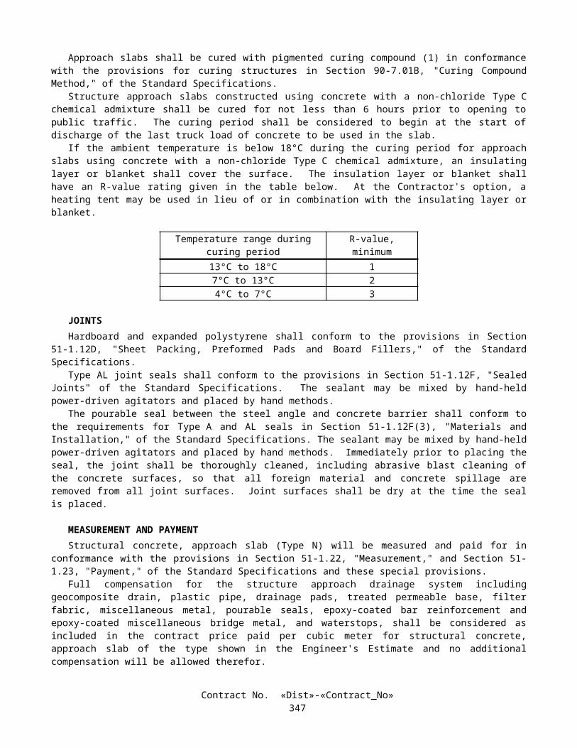
APPROVED MATERIALS LIST
SPEC* MANUFACTURERSUBJECT REFERENCE (Brand Name) NOTES
WATER MAINS
Valves
Gate Valves75 mm through 1200 mm
(a) All internal parts to be bronze(b) 300 mm diameter and larger to be mounted horizontally with by-passes and enclosed gear cases 75 mm thru 300 mm diameter-150 psi working pressure
*207-21.3AWWA C-500
1.Mueller A2380-92062.Kennedy3.American Flow Control4. Iowa-Eddy-Clow
Resilient-Seat-Gate Valves 75 mm thru 300 mm diameter (NRS)
AWWA C-509 ClowAmerican Flow ControlAmerican Flow Control (AFC 500)M & HAmerican AVK (Series 25)KennedyStockhamU.S. Pipe Metroseal (250)
Rubber-Seated Butterfly Valves
*207-21.4 BIF Class 150B
150 mm thru 300 mm diameter
M & H (Dresser)Mueller
400 mm thru 1200 mm diameter
KennedyAmerican-DarlingKeystone (fig. 504/507)Mueller
150 mm thru 300 mm diameter
American-DarlingBIFPrattKeystone (fig. 47)
Plug valves 100 mm Dezurik Series 100, Fig. 118RS17ANG
Plug valves 300 mm Dezurik 100, Fig. 118 RS17AGG12H12
Combination Air & Vacuum Valves
(25 mm,50 mm,75 mm &100 mm diameters)All internal parts to be stainless steel or bronze
1. APCO 143C145C147C149C
2. ValMatic 201C202C
3. GA Industries, Inc. #945
Automatic Control Valves CLA VAL Co.GA industries
* The "Standard Specifications for Public Works Construction" section number or other Reference
Contract No. «Dist»-«Contract_No»350

APPROVED MATERIALS LIST
SPEC* MANUFACTURERSUBJECT REFERENCE (Brand Name) NOTES
Fire Hydrants
Fire Hydrants
Wet Barrel Fire Hydrants for ordinary water works service
(Hydrants with one-piece barrel only, no welded ports allowed)
AWWA C-503 1.Clow - Rich
2.Long Beach Iron
3 James Jones
4 Mueller
Ranger 850, 860, 950, 960
Lido 702, 704Anacapa 614, 615, 425, 430, B-125, B-133, B-135
3700 seriesJ-4040J-4060C
A-481
Meter Boxes
Concrete Water Meter Box *207-21.1SDW 112, 113
Brooks ProductsAssociated Concrete ProductsSan Diego PrecastEisel Enterprise (Nos. 6 and 37)
Water Distribution Pressure Pipe
Polyvinyl Chloride PVC) Pipe, Class 150 or 200100 mm through300 mm diameter
207-18AWWA C-900 and C905
Any Manufacturer Meeting SpecificationsPipe ends-Plain by gasket bell or plain by plain with gasket bell couplings.
Marking Pressure ClassAWWA C-900NSF CertificationPipe ends-plain/gasket bell or plain/plain with gasket bell couplings
Ductile Iron (Dl) pipe100 mm through 1380 mm diameter
207-9AWWA C-111AWWA C-151
Any Manufacturer Meeting Specifications
Polyvinyl Chloride (PVC) pipe, 350 mm” thru 900 mm diameter
*207-18.1AWWA C-905DR-18
Any Manufacturer Meeting Specification Pressure Rating 235 psi
Water Distribution Miscellaneous
Cast Iron & Ductile Iron Fittings and Joints For DI & PVC pipe, short body, cement lined
*207-9.2AWWA C-110AWWA C-111AWWA C-153
Any Manufacturer Meeting Specifications
Only mechanical joint fittings shall be used on PVC pipe
Tapping Sleeve 100 mm thru500 mm diameter
International (228)APAC (502)Baker (428)ford (FTSC)Mueller (H619)Clow-RichImproved CoreySmith-Blair (622)JCM (412)Romac (FTS420)
* The "Standard Specifications for Public Works Construction" section number or other Reference
Contract No. «Dist»-«Contract_No»351

APPROVED MATERIALS LIST
SPEC* MANUFACTURERSUBJECT REFERENCE (Brand Name) NOTES
Stainless Steel Bands(Repair Clamps)
JCM (101, 210, 211, 301)Ford (FS1, FS2)Romac (SS1, SS2)Cascade (CR1, CR2, CR3)
D.I.P. Joints Raychem Hotcladv 110 heat shrinkable
High Deflection fittings, and restrained expansion couplings
U.S. pipe XTRA FLEWX
Paint and Protective Coveringon Welded Steel Pipe
Primer: 1) Ameron Amercoat 31272) Engard 3) Koppers
Amercoat 3127511P-1500 Inorganic Zinc
Intermediate Coat: 1) Ameron2) Engard 3) Koppers
Amercoat 385480Hi-Gard Epoxy
Top Coat 1) Ameron2) Engard3) Koppers
Amershield4482501
Dry Standpipe
Hose valve Potter Roemer Inc. Series 4300
Telescoping Sleeve TR-FLEX Cathodic Protection
Test Station Housing 1) Christy Concrete Products Inc2) Brooks Products
G5 Utility BoxNo. lRT Utility Box
Bitumastic Coating 1) Tapecoat Company2) Kopcoat Inc.
TC MasticBitumastic 505
Weld Caps 1) Royston Laboratories, Inc.
2) Phillips Petroleum Co.
Royston Handy CapThermit Weld Cap
Polymer Mortar 1. Engard Coatings
2. Sika Corporation
3. Fluid Polymer
4. RAM NEK
490 Epoxy Putty or 498 Underwater Epoxy PuttySikadur 31 Hi-Mod Gel or Sikadur 32 Hi-ModFP 1212 polyurethane sealant
FP 1212 polyurethane sealant
Coal Tar Emulsion Koppers Bituplastic No. 28* The "Standard Specifications for Public Works Construction" section number or other Reference
Contract No. «Dist»-«Contract_No»352

APPROVED MATERIALS LIST
SPEC* MANUFACTURERSUBJECT REFERENCE (Brand Name) NOTES
Miscellaneous
Flexible Couplings Smith-Blair 441 RockwellAPAC (331, 332, 323, 335)Cascade, (CDC-EC)DFW, Plastics, Inc.Romac (501)
Eccentric couplings NOT acceptable
Transition Gaskets Atsm D-1869 Newby Rubber, Inc Class 150DR-18 PVC
High-Deflection Coupling 4” thru 12” diameter
Certainteed
Flexible-Saddles (Wye) DFW Plastics, Inc.* The "Standard Specifications for Public Works Construction" section number or other Reference
Contract No. «Dist»-«Contract_No»353

City of San Diego Approved Materials List
BRONZE WATER SERVICE FITTINGS COMPRESSION/PACKINGAPPROVED
SIZE MANUFACTURER'S MODEL NUMBERSTYPE mm Ford Jones McDonald Mueller
CORPORATION STOP** AWWA THREAD TO TUBING 25 mm F-1000 J-3401 4701-22 H-15008 MIP TO TUBING 25 mm F-1100 J-3403 4704-22 H-15028
CURB STOP, ANGLE** IPS THREAD TO METER 50 mm PVC SCHEDULE 40 TO METER
(elongated holes for 38 mm&50 mm meters)
50 mm FV73-777W J-1979
TUBING TO METER 25 mm BA43-444W J-1963 4602B-22 B-24258 TUBING TO METER
(elongated holes for 38 mm& 50 mm meters)
50 mm BF43-777W J-1975 4604-B B-24276
CORPORATE STOP, BALL MIP TO MIP 50 mm J-1943 3131-B MIP TO PVC SCHEDULE 40 50 mm FB-1102 J-1977 MIP TO TUBING 25-50 FB-1100 J-1935 4704B-22 B-25028
BRONZE WATER SERVICE FITTINGS (Cont'd)
FLARED COPPERAPPROVED
MISCELLANEOUSAPPROVED MANU-
SIZE MANUFACTURER'S MODEL NUMBERS FACTURER'S MODEL NUMBERSTYPE mm Ford Jones McDonald Mueller Ford Jones Mueller
CORPORATION STOP** AWWA THREAD TO TUBING 25 mm F-600 J-1500 4701 H-15000 MIP TO TUBING 25 mm F-700 J-1505 4704 H-15025
CURB STOP, ANGLE** IPS THREAD TO METER 50 mm FV13-777W J-1527F H-14286 PVC SCHEDULE 40 TO METER
(elongated holes for 38 mm&50 mm meters)
50 mm
TUBING TO METER 25 mm BA23-444W J-1964 4602B B-24255 TUBING TO METER
(elongated holes for 38 mm& 50 mm meters)
50 mm BFA23-777W J-1973W
CORPORATE STOP, BALL MIP TO MIP 50 mm FB-500 J-1943 H-9969 MIP TO PVC SCHEDULE 40 50 mm MIP TO TUBING 25-50 FB-700 J-1930 4704B B-25025
**Equivalent Ball Valves are acceptable
Contract No. «Dist»-«Contract_No»354

City of San Diego Approved Materials List (Cont'd)
BRONZE WATER SERVICE FITTINGS (Cont'd)
COMPRESSION/PACKINGAPPROVED
SIZE MANUFACTURER'S MODEL NUMBERSTYPE mm Ford Jones McDonald Mueller
COUPLING, ADAPTER FIP TO IPS 25 mm C16-44 J-2608 4754-33 H-15454 FIP TO PVC, IPS 50 mm C17-44 J-2640 FIP TO TUBING 50 mm C14-77 J-2607 4754-22 H-15451 MIP TO PVC, IPS 50 mm C87-77 J-2640 MIP TO TUBING 25 mm C84-44 J-2605 4753-22 H-15428 MIP TO TUBING 50 mm C84-77 J-2605 4753-22 H-15428COUPLING, STRAIGHT METER TAIL 25 mm METER TAIL 19 mm PVC TO PVC SCHEDULE 40 50 mm C77-77 J-2642 TUBING TO TUBING 25 mm C44-44 J-2609 4758-22 H-15403 TUBING TO TUBING 50 mm C44-77 J-2609 4758-22 H-15403PACKING JOINT, 90 DEGREE ELBOW TUBING TO TUBING 50 mm L44-77 J-2611 H-15526VALVE, METER FIP TO METER 25 mm B13-444 J-1908 6101-M
w/6120 Handle
B-24351 w/ B20248 Handle
BRONZE WATER SERVICE FITTINGS (Cont'd)
FLARED COPPERAPPROVED
MISCELLANEOUSAPPROVED MANU-
SIZE MANUFACTURER'S MODEL NUMBERS FACTURER'S MODEL NUMBERSTYPE mm Ford Jones McDonald Mueller Ford Jones Mueller
COUPLING, ADAPTER FIP TO IPS 25 mm FIP TO PVC, IPS 50 mm FIP TO TUBING 50 mm C21-77 J-1535 4754 H-15450 MIP TO PVC, IPS 50 mm MIP TO TUBING 25 mm C28-44 J-1531 4753 H-15425 MIP TO TUBING 50 mm C28-77 J-1531 4753 H-15425COUPLING, STRAIGHT METER TAIL 25 mm C-38 J-130 H-10890 METER TAIL 19 mm C-38 J-130 H-10890 PVC TO PVC SCHEDULE 40 50 mm TUBING TO TUBING 25 mm C22-44 J-1528 4758 H-15400 TUBING TO TUBING 50 mm C22-77 J-1528 4758 H-15400PACKING JOINT, 90 DEGREE ELBOW TUBING TO TUBING 50 mm C22-77 J-1552 4761 H-15525VALVE, METER FIP TO METER 25 mm
**Equivalent Ball Valves are acceptable
Contract No. «Dist»-«Contract_No»355

SECTION 11. MODIFIED STANDARD SPECIFICATION SECTIONSSECTION 11-1. (BLANK)
SECTION 11-2. PORTLAND CEMENT CONCRETE
11-2.01 GENERALPortland cement concrete shall conform to the provisions in this Section 11-2, "Portland Cement Concrete," and the
section entitled "Portland Cement Concrete" in Section 8, "Materials," of these special provisions. Section 90, "Portland Cement Concrete," of the Standard Specifications is deleted. Section 90, "Portland Cement Concrete," of the Standard Specifications is amended to read as follows.
SECTION 90: PORTLAND CEMENT CONCRETE90-1 GENERAL
90-1.01 DESCRIPTION Portland cement concrete shall be composed of cementitious material, fine aggregate, coarse aggregate, admixtures
if used, and water, proportioned and mixed as specified in these specifications. The Contractor shall determine the mix proportions for all concrete except pavement concrete. The Engineer will
determine the mix proportions for pavement concrete. Concrete for which the mix proportions are determined either by the Contractor or the Engineer shall conform to the requirements of this Section 90.
Unless otherwise specified, cementitious material shall be a combination of cement and mineral admixture. Cementitious material shall be either:
1. "Type IP (MS) Modified" cement; or 2. A combination of "Type II Modified" portland cement and mineral admixture; or3. A combination of Type V portland cement and mineral admixture.
Type III portland cement shall be used only as allowed in the special provisions or with the approval of the Engineer.
Class 1 concrete shall contain not less than 400 kg of cementitious material per cubic meter. Class 2 concrete shall contain not less than 350 kg of cementitious material per cubic meter. Class 3 concrete shall contain not less than 300 kg of cementitious material per cubic meter. Class 4 concrete shall contain not less than 250 kg of cementitious material per cubic meter. Minor concrete shall contain not less than 325 kg of cementitious material per cubic meter unless otherwise
specified in these specifications or the special provisions. Unless otherwise designated on the plans or specified in these specifications or the special provisions, the amount of
cementitious material used per cubic meter of concrete in structures or portions of structures shall conform to the following:
Use Cementitious Material Content(kg/m3)
Concrete designated by compressive strength:Deck slabs and slab spans of bridgesRoof sections of exposed top box culvertsOther portions of structures
400 min., 475 max.400 min., 475 max.350 min., 475 max.
Concrete not designated by compressive strength:Deck slabs and slab spans of bridgesRoof sections of exposed top box culvertsPrestressed membersSeal coursesOther portions of structures
400 min.400 min.400 min.400 min.350 min.
Concrete for precast members 350 min., 550 max.
Whenever the 28-day compressive strength shown on the plans is greater than 25 MPa, the concrete shall be designated by compressive strength. If the plans show a 28-day compressive strength that is 28 MPa or greater, an additional 14 days will be allowed to obtain the specified strength. The 28-day compressive strengths shown on the plans that are 25 MPa or less are shown for design information only and are not a requirement for acceptance of the concrete.
Contract No. «Dist»-«Contract_No»356
Concrete designated by compressive strength shall be proportioned such that the concrete will attain the strength shown on the plans or specified in the special provisions.
Before using concrete for which the mix proportions have been determined by the Contractor, or in advance of revising those mix proportions, the Contractor shall submit in writing to the Engineer a copy of the mix design.
Compliance with cementitious material content requirements will be verified in conformance with procedures described in California Test 518 for cement content. For testing purposes, mineral admixture shall be considered to be cement. Batch proportions shall be adjusted as necessary to produce concrete having the specified cementitious material content.
If any concrete has a cementitious material, portland cement, or mineral admixture content that is less than the minimum required, the concrete shall be removed. However, if the Engineer determines that the concrete is structurally adequate, the concrete may remain in place and the Contractor shall pay to the State $0.55 for each kilogram of cementitious material, portland cement, or mineral admixture that is less than the minimum required. The Department may deduct the amount from any moneys due, or that may become due, the Contractor under the contract. The deductions will not be made unless the difference between the contents required and those actually provided exceeds the batching tolerances permitted by Section 90-5, "Proportioning." No deductions will be made based on the results of California Test 518.
The requirements of the preceding paragraph shall not apply to minor concrete or commercial quality concrete.
90-2 MATERIALS
90-2.01 CEMENT Unless otherwise specified, cement shall be either "Type IP (MS) Modified" cement, "Type II Modified" portland
cement or Type V portland cement. "Type IP (MS) Modified" cement shall conform to the requirements for Type IP (MS) cement in ASTM
Designation: C 595, and shall be comprised of an intimate and uniform blend of Type II cement and not more than 35 percent by mass of mineral admixture. The type and minimum amount of mineral admixture used in the manufacture of "Type IP (MS) Modified" cement shall be in conformance with the provisions in Section 90-4.08, "Required Use of Mineral Admixtures."
"Type II Modified" portland cement shall conform to the requirements for Type II portland cement in ASTM Designation: C 150.
In addition, "Type IP (MS) Modified" cement and "Type II Modified" portland cement shall conform to the following requirements:
A. The cement shall not contain more than 0.60 percent by mass of alkalies, calculated as the percentage of Na2O plus 0.658 times the percentage of K2O, when determined by either direct intensity flame photometry or by the atomic absorption method. The instrument and procedure used shall be qualified as to precision and accuracy in conformance with the requirements in ASTM Designation: C 114;
B. The autoclave expansion shall not exceed 0.50 percent; andC. Mortar, containing the cement to be used and Ottawa sand, when tested in conformance with California Test 527,
shall not expand in water more than 0.010 percent and shall not contract in air more than 0.048 percent, except that when cement is to be used for precast prestressed concrete piling, precast prestressed concrete members, or steam cured concrete products, the mortar shall not contract in air more than 0.053 percent.
Type III and Type V portland cements shall conform to the requirements in ASTM Designation: C 150 and the additional requirements listed above for "Type II Modified" portland cement, except that when tested in conformance with California Test 527, mortar containing Type III portland cement shall not contract in air more than 0.075 percent.
Cement used in the manufacture of cast-in-place concrete for exposed surfaces of like elements of a structure shall be from the same cement mill.
Cement shall be protected from exposure to moisture until used. Sacked cement shall be piled to permit access for tally, inspection, and identification of each shipment.
Adequate facilities shall be provided to assure that cement meeting the provisions specified in this Section 90 -2.01 shall be kept separate from other cement in order to prevent any but the specified cement from entering the work. Safe and suitable facilities for sampling cement shall be provided at the weigh hopper or in the feed line immediately in advance of the hopper, in conformance with California Test 125.
If cement is used prior to sampling and testing as provided in Section 6-1.07, "Certificates of Compliance," and the cement is delivered directly to the site of the work, the Certificate of Compliance shall be signed by the cement manufacturer or supplier of the cement. If the cement is used in ready-mixed concrete or in precast concrete products purchased as such by the Contractor, the Certificate of Compliance shall be signed by the manufacturer of the concrete or product.
Contract No. «Dist»-«Contract_No»357
Cement furnished without a Certificate of Compliance shall not be used in the work until the Engineer has had sufficient time to make appropriate tests and has approved the cement for use.
90-2.02 AGGREGATES Aggregates shall be free from deleterious coatings, clay balls, roots, bark, sticks, rags, and other extraneous material. Natural aggregates shall be thoroughly and uniformly washed before use. The Contractor, at the Contractor's expense, shall provide safe and suitable facilities, including necessary splitting
devices for obtaining samples of aggregates, in conformance with California Test 125. Aggregates shall be of such character that it will be possible to produce workable concrete within the limits of water
content provided in Section 90-6.06, "Amount of Water and Penetration." Aggregates shall have not more than 10 percent loss when tested for soundness in conformance with the
requirements in California Test 214. The soundness requirement for fine aggregate will be waived, provided that the durability index, Df, of the fine aggregate is 60, or greater, when tested for durability in conformance with California Test 229.
Contract No. «Dist»-«Contract_No»358

If the results of any one or more of the Cleanness Value, Sand Equivalent, or aggregate grading tests do not meet the requirements specified for "Operating Range" but all meet the "Contract Compliance" requirements, the placement of concrete shall be suspended at the completion of the current pour until tests or other information indicate that the next material to be used in the work will comply with the requirements specified for "Operating Range."
If the results of either or both the Cleanness Value and coarse aggregate grading tests do not meet the requirements specified for "Contract Compliance," the concrete that is represented by the tests shall be removed. However, if the Engineer determines that the concrete is structurally adequate, the concrete may remain in place, and the Contractor shall pay to the State $4.60 per cubic meter for paving concrete and $7.20 per cubic meter for all other concrete for the concrete represented by these tests and left in place. The Department may deduct the amount from any moneys due, or that may become due, the Contractor under the contract.
If the results of either or both the Sand Equivalent and fine aggregate grading tests do not meet the requirements specified for "Contract Compliance," the concrete which is represented by the tests shall be removed. However, if the Engineer determines that the concrete is structurally adequate, the concrete may remain in place, and the Contractor shall pay to the State $4.60 per cubic meter for paving concrete and $7.20 per cubic meter for all other concrete for the concrete represented by these tests and left in place. The Department may deduct the amount from any moneys due, or that may become due, the Contractor under the contract.
The 2 preceding paragraphs apply individually to the "Contract Compliance" requirements for coarse aggregate and fine aggregate. When both coarse aggregate and fine aggregate do not conform to the "Contract Compliance" requirements, both paragraphs shall apply. The payments specified in those paragraphs shall be in addition to any payments made in conformance with the provisions in Section 90-1.01, "Description."
No single Cleanness Value, Sand Equivalent or aggregate grading test shall represent more than 250 m3 of concrete or one day's pour, whichever is smaller.
Aggregates specified for freeze-thaw resistance shall pass the freezing and thawing test, California Test 528. The Contractor shall notify the Engineer of the proposed source of freeze-thaw resistant concrete aggregates at least
4 months before intended use. Should the Contractor later propose a different source of concrete aggregates, the Contractor shall again notify the Engineer at least 4 months before intended use. Blending of fine or coarse aggregates from untested sources with acceptable aggregates will not be permitted. Provisions for the time of submission of samples as provided in Section 40-1.015, "Cement Content," are superseded by the foregoing.
Concurrently with notification of proposed sources of freeze-thaw resistant concrete aggregates, the Contractor shall furnish samples in the quantity ordered by the Engineer. The samples shall be secured under the direct supervision of the Engineer. Samples from existing stockpiles of processed aggregate shall be taken from washed materials and shall be visibly damp. Samples from materials in place in a material source shall be taken at depths from the existing surface that will ensure the presence of the full quantity of ground water. Excavations for the purpose of securing samples shall be made to the full depth of intended source operations. Samples shall be protected against loss of contained water until they are delivered to the Engineer.
The Engineer will waive the above freeze-thaw test and the 4-month advance notice, required in this Section, provided aggregates are to be obtained from sources that have previously passed this test and test results are currently applicable.
No extension of contract time will be allowed for the time required to perform the freezing and thawing test. When the source of an aggregate is changed, except for pavement concrete, the Contractor shall adjust the mix
proportions and submit in writing to the Engineer a copy of the mix design before using the aggregates. When the source of an aggregate is changed for pavement concrete, the Engineer shall be allowed sufficient time to adjust the mix, and the aggregates shall not be used until necessary adjustments are made.
90-2.02A Coarse Aggregate Coarse aggregate shall consist of gravel, crushed gravel, crushed rock, crushed air-cooled iron blast furnace slag or
combinations thereof. Crushed air-cooled blast furnace slag shall not be used in reinforced or prestressed concrete. Coarse aggregate shall conform to the following quality requirements:
TestsCalifornia
Test RequirementsLoss in Los Angeles Rattler (after 500 revolutions)
211 45% max.
Cleanness ValueOperating Range 227 75 min.Contract Compliance 227 71 min.
Contract No. «Dist»-«Contract_No»359

In lieu of the above Cleanness Value requirements, a Cleanness Value "Operating Range" limit of 71, minimum, and a Cleanness Value "Contract Compliance" limit of 68, minimum, will be used to determine the acceptability of the coarse aggregate if the Contractor furnishes a Certificate of Compliance, as provided in Section 6-1.07, "Certificates of Compliance," certifying that:
1. coarse aggregate sampled at the completion of processing at the aggregate production plant had a Cleanness Value of not less than 82 when tested by California Test 227; and
2. prequalification tests performed in conformance with the requirements in California Test 549 indicated that the aggregate would develop a relative strength of not less than 95 percent and would have a relative shrinkage not greater than 105 percent, based on concrete.
90-2.02B Fine Aggregate Fine aggregate shall consist of natural sand, manufactured sand produced from larger aggregate or a combination
thereof. Manufactured sand shall be well graded. Fine aggregate shall conform to the following quality requirements:
TestCalifornia
Test RequirementsOrganic Impurities 213 Satisfactorya
Mortar Strengths Relative to Ottawa Sand 515 95%, min.Sand Equivalent:
Operating Range 217 75, min.Contract Compliance 217 71, min.
a Fine aggregate developing a color darker than the reference standard color solution may be accepted if it is determined by the Engineer, from mortar strength tests, that a darker color is acceptable.
In lieu of the above Sand Equivalent requirements, a Sand Equivalent "Operating Range" limit of 71 minimum and a Sand Equivalent "Contract Compliance" limit of 68 minimum will be used to determine the acceptability of the fine aggregate if the Contractor furnishes a Certificate of Compliance, as provided in Section 6-1.07, "Certificates of Compliance," certifying that:
1. fine aggregate sampled at the completion of processing at the aggregate production plant had a Sand Equivalent value of not less than 82 when tested by California Test 217; and
2. prequalification tests performed in conformance with California Test 549 indicated that the aggregate would develop a relative strength of not less than 95 percent and would have a relative shrinkage not greater than 105 percent, based on concrete.
90-2.03 WATER In conventionally reinforced concrete work, the water for curing, for washing aggregates, and for mixing shall be
free from oil and shall not contain more than 1000 parts per million of chlorides as Cl, when tested in conformance with California Test 422, nor more than 1300 parts per million of sulfates as SO4, when tested in conformance with California Test 417. In prestressed concrete work, the water for curing, for washing aggregates, and for mixing shall be free from oil and shall not contain more than 650 parts per million of chlorides as Cl, when tested in conformance with California Test 422, nor more than 1300 parts per million of sulfates as SO4, when tested in conformance with California Test 417. In no case shall the water contain an amount of impurities that will cause either: 1) a change in the setting time of cement of more than 25 percent when tested in conformance with the requirements in ASTM Designation: C 191 or ASTM Designation: C 266 or 2) a reduction in the compressive strength of mortar at 14 days of more than 5 percent, when tested in conformance with the requirements in ASTM Designation: C 109, when compared to the results obtained with distilled water or deionized water, tested in conformance with the requirements in ASTM Designation: C 109.
In non-reinforced concrete work, the water for curing, for washing aggregates and for mixing shall be free from oil and shall not contain more than 2000 parts per million of chlorides as Cl, when tested in conformance with California Test 422, or more than 1500 parts per million of sulfates as SO4, when tested in conformance with California Test 417.
In addition to the above provisions, water for curing concrete shall not contain impurities in a sufficient amount to cause discoloration of the concrete or produce etching of the surface.
Contract No. «Dist»-«Contract_No»360

Water reclaimed from mixer wash-out operations may be used in mixing concrete. The water shall not contain coloring agents or more than 300 parts per million of alkalis (Na2O + 0.658 K2O) as determined on the filtrate. The specific gravity of the water shall not exceed 1.03 and shall not vary more than ±0.010 during a day's operations.
90-2.04 ADMIXTURE MATERIALS Admixture materials shall conform to the requirements in the following ASTM Designations:
A. Chemical Admixtures—ASTM Designation: C 494.B. Air-entraining Admixtures—ASTM Designation: C 260.C. Calcium Chloride—ASTM Designation: D 98.D. Mineral Admixtures—Coal fly ash; raw or calcined natural pozzolan as specified in ASTM Designation: C618;
silica fume conforming to the requirements in ASTM Designation: C1240, with reduction of mortar expansion of 80 percent, minimum, using the cement from the proposed mix design.
Contract No. «Dist»-«Contract_No»361

Unless otherwise specified in the special provisions, mineral admixtures shall be used in conformance with the provisions in Section 90-4.08, "Required Use of Mineral Admixtures."
90-3 AGGREGATE GRADINGS
90-3.01 GENERAL Before beginning concrete work, the Contractor shall submit in writing to the Engineer the gradation of the primary
aggregate nominal sizes that the Contractor proposes to furnish. If a primary coarse aggregate or the fine aggregate is separated into 2 or more sizes, the proposed gradation shall consist of the gradation for each individual size, and the proposed proportions of each individual size, combined mathematically to indicate one proposed gradation. The proposed gradation shall meet the grading requirements shown in the table in this section, and shall show the percentage passing each of the sieve sizes used in determining the end result.
The Engineer may waive, in writing, the gradation requirements in this Section 90-3.01 and in Sections 90-3.02, "Coarse Aggregate Grading," 90-3.03, "Fine Aggregate Grading," and 90-3.04, "Combined Aggregate Gradings," if, in the Engineer's opinion, furnishing the gradation is not necessary for the type or amount of concrete work to be constructed.
Gradations proposed by the Contractor shall be within the following percentage passing limits:
Primary Aggregate Nominal Size Sieve Size Limits of Proposed Gradation37.5-mm x 19-mm 25-mm 19 - 4125-mm x 4.75-mm 19-mm 52 - 8525-mm x 4.75-mm 9.5-mm 15 - 3812.5-mm x 4.75-mm 9.5-mm 40 - 78 9.5-mm x 2.36-mm 9.5-mm 50 - 85 Fine Aggregate 1.18-mm 55 - 75Fine Aggregate 600-µm 34 - 46Fine Aggregate 300-µm 16 - 29
Should the Contractor change the source of supply, the Contractor shall submit in writing to the Engineer the new gradations before their intended use.
90-3.02 COARSE AGGREGATE GRADING The grading requirements for coarse aggregates are shown in the following table for each size of coarse aggregate:
Percentage Passing Primary Aggregate Nominal Sizes37.5-mm x 19-mm 25-mm x 4.75-mm 12.5-mm x 4.75-mm 9.5-mm x 2.36-mm
Operating Contract Operating Contract Operating Contract Operating ContractSieve Sizes Range Compliance Range Compliance Range Compliance Range Compliance50-mm 100 100 — — — — — —37.5-mm 88-100 85-100 100 100 — — — —25-mm x ± 18 X ± 25 88-100 86-100 — — — —19-mm 0-17 0-20 X ± 15 X ± 22 100 100 — —12.5-mm — — — — 82-100 80-100 100 1009.5-mm 0-7 0-9 X ± 15 X ± 22 X ± 15 X ± 22 X ± 15 X ± 204.75-mm — — 0-16 0-18 0-15 0-18 0-25 0-282.36-mm — — 0-6 0-7 0-6 0-7 0-6 0-7
In the above table, the symbol X is the gradation that the Contractor proposes to furnish for the specific sieve size as provided in Section 90-3.01, "General."
Coarse aggregate for the 37.5-mm, maximum, combined aggregate grading as provided in Section 90-3.04, "Combined Aggregate Gradings," shall be furnished in 2 or more primary aggregate nominal sizes. Each primary aggregate nominal size may be separated into 2 sizes and stored separately, provided that the combined material conforms to the grading requirements for that particular primary aggregate nominal size.
Contract No. «Dist»-«Contract_No»362

When the 25-mm, maximum, combined aggregate grading as provided in Section 90-3.04, "Combined Aggregate Gradings," is to be used, the coarse aggregate may be separated into 2 sizes and stored separately, provided that the combined material shall conform to the grading requirements for the 25-mm x 4.75-mm primary aggregate nominal size.
90-3.03 FINE AGGREGATE GRADING Fine aggregate shall be graded within the following limits:
Percentage PassingSieve Sizes Operating Range Contract Compliance
9.5-mm 100 1004.75-mm 95-100 93-1002.36-mm 65-95 61-991.18-mm X ± 10 X ± 13600-µm X ± 9 X ± 12300-µm X ± 6 X ± 9150-µm 2-12 1-1575-µm 0-8 0-10
Contract No. «Dist»-«Contract_No»363

In the above table, the symbol X is the gradation that the Contractor proposes to furnish for the specific sieve size as provided in Section 90-3.01, "General."
In addition to the above required grading analysis, the distribution of the fine aggregate sizes shall be such that the difference between the total percentage passing the 1.18-mm sieve and the total percentage passing the 600-µm sieve shall be between 10 and 40, and the difference between the percentage passing the 600-µm and 300-µm sieves shall be between 10 and 40.
Fine aggregate may be separated into 2 or more sizes and stored separately, provided that the combined material conforms to the grading requirements specified in this Section 90-3.03.
90-3.04 COMBINED AGGREGATE GRADINGS Combined aggregate grading limits shall be used only for the design of concrete mixes. Concrete mixes shall be
designed so that aggregates are combined in proportions that shall produce a mixture within the grading limits for combined aggregates as specified herein. Within these limitations, the relative proportions shall be as ordered by the Engineer, except as otherwise provided in Section 90-1.01, "Description."
The combined aggregate grading used in portland cement concrete pavement shall be the 37.5-mm, maximum grading.
The combined aggregate grading used in concrete for structures and other concrete items, except when specified otherwise in these specifications or the special provisions, shall be either the 37.5-mm, maximum grading, or the 25-mm, maximum grading, at the option of the Contractor.
Grading Limits of Combined AggregatesPercentage Passing
Sieve Sizes 37.5-mm Max. 25-mm Max. 12.5-mm Max. 9.5-mm Max.50-mm 100 — — —37.5-mm 90-100 100 — —25-mm 50-86 90-100 — —19-mm 45-75 55-100 100 —12.5-mm — — 90-100 1009.5-mm 38-55 45-75 55-86 50 - 1004.75-mm 30-45 35-60 45-63 45 - 632.36-mm 23-38 27-45 35-49 35 - 491.18-mm 17-33 20-35 25-37 25 - 37600-µm 10-22 12-25 15-25 15 - 25300-µm 4-10 5-15 5-15 5 - 15150-µm 1-6 1-8 1-8 1 - 875-µm 0-3 0-4 0-4 0 - 4
Changes from one grading to another shall not be made during the progress of the work unless permitted by the Engineer.
90-4 ADMIXTURES90-4.01 GENERAL
Admixtures used in portland cement concrete shall conform to and be used in conformance with the provisions in this Section 90-4 and the special provisions. Admixtures shall be used when specified or ordered by the Engineer and may be used at the Contractor's option as provided herein.
Chemical admixtures and air-entraining admixtures containing chlorides as Cl in excess of one percent by mass of admixture, as determined by California Test 415, shall not be used in prestressed or reinforced concrete.
Calcium chloride shall not be used in concrete containing steel reinforcement or other embedded metals. Mineral admixture used in concrete for exposed surfaces of like elements of a structure shall be from the same
source and of the same percentage. Admixtures shall be uniform in properties throughout their use in the work. Should it be found that an admixture as
furnished is not uniform in properties, its use shall be discontinued. If more than one admixture is used, the admixtures shall be compatible with each other so that the desirable effects
of all admixtures used will be realized.
Contract No. «Dist»-«Contract_No»364

90-4.02 MATERIALS Admixture materials shall conform to the provisions in Section 90–2.04, "Admixture Materials."
90-4.03 ADMIXTURE APPROVAL No admixture brand shall be used in the work unless it is on the Department's current list of approved brands for the
type of admixture involved. Admixture brands will be considered for addition to the approved list if the manufacturer of the admixture submits
to the Transportation Laboratory a sample of the admixture accompanied by certified test results demonstrating that the admixture complies with the requirements in the appropriate ASTM Designation and these specifications. The sample shall be sufficient to permit performance of all required tests. Approval of admixture brands will be dependent upon a determination as to compliance with the requirements, based on the certified test results submitted, together with tests the Department may elect to perform.
When the Contractor proposes to use an admixture of a brand and type on the current list of approved admixture brands, the Contractor shall furnish a Certificate of Compliance from the manufacturer, as provided in Section 6 -1.07, "Certificates of Compliance," certifying that the admixture furnished is the same as that previously approved. If a previously approved admixture is not accompanied by a Certificate of Compliance, the admixture shall not be used in the work until the Engineer has had sufficient time to make the appropriate tests and has approved the admixture for use. The Engineer may take samples for testing at any time, whether or not the admixture has been accompanied by a Certificate of Compliance.
If a mineral admixture is delivered directly to the site of the work, the Certificate of Compliance shall be signed by the manufacturer or supplier of the mineral admixture. If the mineral admixture is used in ready-mix concrete or in precast concrete products purchased as such by the Contractor, the Certificate of Compliance shall be signed by the manufacturer of the concrete or product.
90-4.04 REQUIRED USE OF CHEMICAL ADMIXTURES AND CALCIUM CHLORIDE When the use of a chemical admixture or calcium chloride is specified or ordered by the Engineer, the admixture
shall be used at the dosage specified or ordered, except that if no dosage is specified or ordered, the admixture shall be used at the dosage normally recommended by the manufacturer of the admixture.
Calcium chloride shall be dispensed in liquid, flake, or pellet form. Calcium chloride dispensed in liquid form shall conform to the provisions for dispensing liquid admixtures in Section 90-4.10, "Proportioning and Dispensing Liquid Admixtures."
90-4.05 OPTIONAL USE OF CHEMICAL ADMIXTURES The Contractor will be permitted to use Type A or F, water-reducing; Type B, retarding; or Type D or G, water-
reducing and retarding admixtures as described in ASTM Designation: C 494 to conserve cementitious material or to facilitate any concrete construction application subject to the following conditions:
A. When a water-reducing admixture or a water-reducing and retarding admixture is used, the cementitious material content specified or ordered may be reduced by a maximum of 5 percent by mass, except that the resultant cementitious material content shall be not less than 300 kilograms per cubic meter; and
B. When a reduction in cementitious material content is made, the dosage of admixture used shall be the dosage used in determining approval of the admixture.
Unless otherwise specified, a Type C accelerating chemical admixture conforming to the requirements in ASTM Designation: C 494, may be used in portland cement concrete. Inclusion in the mix design submitted for approval will not be required provided that the admixture is added to counteract changing conditions that contribute to delayed setting of the portland cement concrete, and the use or change in dosage of the admixture is approved in writing by the Engineer.
90-4.06 REQUIRED USE OF AIR-ENTRAINING ADMIXTURES When air-entrainment is specified or ordered by the Engineer, the air-entraining admixture shall be used in amounts
to produce a concrete having the specified air content as determined by California Test 504.
90-4.07 OPTIONAL USE OF AIR-ENTRAINING ADMIXTURES When air-entrainment has not been specified or ordered by the Engineer, the Contractor will be permitted to use an
air-entraining admixture to facilitate the use of any construction procedure or equipment provided that the average air content, as determined by California Test 504, of 3 successive tests does not exceed 4 percent, and no single test value exceeds 5.5 percent. If the Contractor elects to use an air-entraining admixture in concrete for pavement, the Contractor shall so indicate at the time the Contractor designates the source of aggregate as provided in Section 40-1.015, "Cement Content."
Contract No. «Dist»-«Contract_No»365
90-4.08 REQUIRED USE OF MINERAL ADMIXTURES Unless otherwise specified, mineral admixture shall be combined with cement to make cementitious material. The calcium oxide content of mineral admixtures shall not exceed 10 percent and the available alkali, as sodium
oxide equivalent, shall not exceed 1.5 percent when determined in conformance with the requirements in ASTM Designation: C 618.
The amounts of cement and mineral admixture used in cementitious material shall be sufficient to satisfy the minimum cementitious material content requirements specified in Section 90-1.01, "Description," or Section 90-4.05, "Optional Use of Chemical Admixtures," and shall conform to the following:
A. The minimum amount of cement shall not be less than 75 percent by mass of the specified minimum cementitious material content;
B. The minimum amount of mineral admixture to be combined with cement shall be determined using one of the following criteria:
1. When the calcium oxide content of a mineral admixture is equal to or less than 2 percent by mass, the amount of mineral admixture shall not be less than 15 percent by mass of the total amount of cementitious material to be used in the mix;
2. When the calcium oxide content of a mineral admixture is greater than 2 percent, the amount of mineral admixture shall not be less than 25 percent by mass of the total amount of cementitious material to be used in the mix;
3. When a mineral admixture that conforms to the provisions for silica fume in Section 90-2.04, "Admixture Materials," is used, the amount of mineral admixture shall not be less than 10 percent by mass of the total amount of cementitious material to be used in the mix
C. The total amount of mineral admixture shall not exceed 35 percent by mass of the total amount of cementitious material to be used in the mix. Where Section 90-1.01, "Description," specifies a maximum cementitious content in kilograms per cubic meter, the total mass of cement and mineral admixture per cubic meter shall not exceed the specified maximum cementitious material content.
90-4.09 BLANK
90-4.10 PROPORTIONING AND DISPENSING LIQUID ADMIXTURES Chemical admixtures and air-entraining admixtures shall be dispensed in liquid form. Dispensers for liquid
admixtures shall have sufficient capacity to measure at one time the prescribed quantity required for each batch of concrete. Each dispenser shall include a graduated measuring unit into which liquid admixtures are measured to within ±5 percent of the prescribed quantity for each batch. Dispensers shall be located and maintained so that the graduations can be accurately read from the point at which proportioning operations are controlled to permit a visual check of batching accuracy prior to discharge. Each measuring unit shall be clearly marked for the type and quantity of admixture.
Each liquid admixture dispensing system shall be equipped with a sampling device consisting of a valve located in a safe and readily accessible position such that a sample of the admixture may be withdrawn slowly by the Engineer.
If more than one liquid admixture is used in the concrete mix, each liquid admixture shall have a separate measuring unit and shall be dispensed by injecting equipment located in such a manner that the admixtures are not mixed at high concentrations and do not interfere with the effectiveness of each other. When air -entraining admixtures are used in conjunction with other liquid admixtures, the air-entraining admixture shall be the first to be incorporated into the mix.
When automatic proportioning devices are required for concrete pavement, dispensers for liquid admixtures shall operate automatically with the batching control equipment. The dispensers shall be equipped with an automatic warning system in good operating condition that will provide a visible or audible signal at the point at which proportioning operations are controlled when the quantity of admixture measured for each batch of concrete varies from the preselected dosage by more than 5 percent, or when the entire contents of the measuring unit are not emptied from the dispenser into each batch of concrete.
Unless liquid admixtures are added to premeasured water for the batch, their discharge into the batch shall be arranged to flow into the stream of water so that the admixtures are well dispersed throughout the batch, except that air-entraining admixtures may be dispensed directly into moist sand in the batching bins provided that adequate control of the air content of the concrete can be maintained.
Liquid admixtures requiring dosages greater than 2.5 L/m3 shall be considered to be water when determining the total amount of free water as specified in Section 90-6.06, "Amount of Water and Penetration."
Contract No. «Dist»-«Contract_No»366

Special admixtures, such as "high range" water reducers that may contribute to a high rate of slump loss, shall be measured and dispensed as recommended by the admixture manufacturer and as approved by the Engineer.
90-4.11 STORAGE, PROPORTIONING, AND DISPENSING OF MINERAL ADMIXTURES Mineral admixtures shall be protected from exposure to moisture until used. Sacked material shall be piled to permit
access for tally, inspection and identification for each shipment. Adequate facilities shall be provided to assure that mineral admixtures meeting the specified requirements are kept
separate from other mineral admixtures in order to prevent any but the specified mineral admixtures from entering the work. Safe and suitable facilities for sampling mineral admixtures shall be provided at the weigh hopper or in the feed line immediately in advance of the hopper.
Mineral admixtures shall be incorporated into concrete using equipment conforming to the requirements for cement weigh hoppers, and charging and discharging mechanisms in ASTM Designation: C 94, in Section 90-5.03, "Proportioning," and in this Section 90-4.11.
When concrete is completely mixed in stationary paving mixers, the mineral admixture shall be weighed in a separate weigh hopper conforming to the provisions for cement weigh hoppers and charging and discharging mechanisms in Section 90-5.03A, "Proportioning for Pavement," and the mineral admixture and cement shall be introduced simultaneously into the mixer proportionately with the aggregate. If the mineral admixture is not weighed in a separate weigh hopper, the Contractor shall provide certification that the stationary mixer is capable of mixing the cement, admixture, aggregates and water uniformly prior to discharge. Certification shall contain the following:
A. Test results for 2 compressive strength test cylinders of concrete taken within the first one-third and 2 compressive strength test cylinders of concrete taken within the last one-third of the concrete discharged from a single batch from the stationary paving mixer. Strength tests and cylinder preparation will be in conformance with the provisions of Section 90-9, "Compressive Strength;"
B. Calculations demonstrating that the difference in the averages of 2 compressive strengths taken in the first one-third is no greater than 7.5 percent different than the averages of 2 compressive strengths taken in the last one-third of the concrete discharged from a single batch from the stationary paving mixer. Strength tests and cylinder preparation will be in conformance with the provisions of Section 90-9, "Compressive Strength;" and
C. The mixer rotation speed and time of mixing prior to discharge that are required to produce a mix that meets the requirements above.
90-5 PROPORTIONING
90-5.01 STORAGE OF AGGREGATES Aggregates shall be stored or stockpiled in such a manner that separation of coarse and fine particles of each size
shall be avoided and also that the various sizes shall not become intermixed before proportioning. Aggregates shall be stored or stockpiled and handled in a manner that shall prevent contamination by foreign
materials. In addition, storage of aggregates at batching or mixing facilities that are erected subsequent to the award of the contract and that furnish concrete to the project shall conform to the following:
A. Intermingling of the different sizes of aggregates shall be positively prevented. The Contractor shall take the necessary measures to prevent intermingling. The preventive measures may include, but are not necessarily limited to, physical separation of stockpiles or construction of bulkheads of adequate length and height; and
B. Contamination of aggregates by contact with the ground shall be positively prevented. The Contractor shall take the necessary measures to prevent contamination. The preventive measures shall include, but are not necessarily limited to, placing aggregates on wooden platforms or on hardened surfaces consisting of portland cement concrete, asphalt concrete, or cement treated material.
In placing aggregates in storage or in moving the aggregates from storage to the weigh hopper of the batching plant, any method that may cause segregation, degradation, or the combining of materials of different gradings that will result in any size of aggregate at the weigh hopper failing to meet the grading requirements, shall be discontinued. Any method of handling aggregates that results in excessive breakage of particles shall be discontinued. The use of suitable devices to reduce impact of falling aggregates may be required by the Engineer.
90-5.02 PROPORTIONING DEVICES Weighing, measuring, or metering devices used for proportioning materials shall conform to the requirements in
Section 9-1.01, "Measurement of Quantities," and this Section 90-5.02. In addition, automatic weighing systems shall
Contract No. «Dist»-«Contract_No»367

comply with the requirements for automatic proportioning devices in Section 90-5.03A, "Proportioning for Pavement." Automatic devices shall be automatic to the extent that the only manual operation required for proportioning the aggregates, cement, and mineral admixture for one batch of concrete is a single operation of a switch or starter.
Proportioning devices shall be tested at the expense of the Contractor as frequently as the Engineer may deem necessary to ensure their accuracy.
Weighing equipment shall be insulated against vibration or movement of other operating equipment in the plant. When the plant is in operation, the mass of each batch of material shall not vary from the mass designated by the Engineer by more than the tolerances specified herein.
Equipment for cumulative weighing of aggregate shall have a zero tolerance of ±0.5 percent of the designated total batch mass of the aggregate. For systems with individual weigh hoppers for the various sizes of aggregate, the zero tolerance shall be ±0.5 percent of the individual batch mass designated for each size of aggregate. Equipment for cumulative weighing of cement and mineral admixtures shall have a zero tolerance of ±0.5 percent of the designated total batch mass of the cement and mineral admixture. Equipment for weighing cement or mineral admixture separately shall have a zero tolerance of ±0.5 percent of their designated individual batch masses. Equipment for measuring water shall have a zero tolerance of ±0.5 percent of its designated mass or volume.
The mass indicated for any batch of material shall not vary from the preselected scale setting by more than the following:
A. Aggregate weighed cumulatively shall be within 1.0 percent of the designated total batch mass of the aggregate. Aggregates weighed individually shall be within 1.5 percent of their respective designated batch masses; and
B. Cement shall be within 1.0 percent of its designated batch mass. When weighed individually, mineral admixture shall be within 1.0 percent of its designated batch mass. When mineral admixture and cement are permitted to be weighed cumulatively, cement shall be weighed first to within 1.0 percent of its designated batch mass, and the total for cement and mineral admixture shall be within 1.0 percent of the sum of their designated batch masses; and
C. Water shall be within 1.5 percent of its designated mass or volume.
Each scale graduation shall be approximately 0.001 of the total capacity of the scale. The capacity of scales for weighing cement, mineral admixture, or cement plus mineral admixture and aggregates shall not exceed that of commercially available scales having single graduations indicating a mass not exceeding the maximum permissible mass variation above, except that no scale shall be required having a capacity of less than 500 kg, with 0.5-kg graduations.
90-5.03 PROPORTIONING Proportioning shall consist of dividing the aggregates into the specified sizes, each stored in a separate bin, and
combining them with cement, mineral admixture, and water as provided in these specifications. Aggregates shall be proportioned by mass.
At the time of batching, aggregates shall have been dried or drained sufficiently to result in a stable moisture content such that no visible separation of water from aggregate will take place during transportation from the proportioning plant to the point of mixing. In no event shall the free moisture content of the fine aggregate at the time of batching exceed 8 percent of its saturated, surface-dry mass.
Should separate supplies of aggregate material of the same size group, but of different moisture content or specific gravity or surface characteristics affecting workability, be available at the proportioning plant, withdrawals shall be made from one supply exclusively and the materials therein completely exhausted before starting upon another.
Bulk "Type IP (MS) Modified" cement shall be weighed in an individual hopper and shall be kept separate from the aggregates until the ingredients are released for discharge into the mixer.
Bulk cement and mineral admixture may be weighed in separate, individual weigh hoppers or may be weighed in the same weigh hopper and shall be kept separate from the aggregates until the ingredients are released for discharge into the mixer. If the cement and mineral admixture are weighed cumulatively, the cement shall be weighed first.
When cement and mineral admixtures are weighed in separate weigh hoppers , the weigh systems for the proportioning of the aggregate, the cement, and the mineral admixture shall be individual and distinct from all other weigh systems. Each weigh system shall be equipped with a hopper, a lever system, and an indicator to constitute an individual and independent material weighing device. The cement and the mineral admixture shall be discharged into the mixer simultaneously with the aggregate.
The scales and weigh hoppers for bulk weighing cement, mineral admixture, or cement plus mineral admixture shall be separate and distinct from the aggregate weighing equipment.
For batches with a volume of one cubic meter or more, the batching equipment shall conform to one of the following combinations:
A. Separate boxes and separate scale and indicator for weighing each size of aggregate.
Contract No. «Dist»-«Contract_No»368

B. Single box and scale indicator for all aggregates.C. Single box or separate boxes and automatic weighing mechanism for all aggregates.
In order to check the accuracy of batch masses, the gross mass and tare mass of batch trucks, truck mixers, truck agitators, and non-agitating hauling equipment shall be determined when ordered by the Engineer. The equipment shall be weighed at the Contractor’s expense on scales designated by the Engineer.
90-5.03A Proportioning for Pavement Aggregates and bulk cement, mineral admixture, and cement plus mineral admixture for use in pavement shall be
proportioned by mass by means of automatic proportioning devices of approved type conforming to these specifications. The Contractor shall install and maintain in operating condition an electronically actuated moisture meter that will
indicate, on a readily visible scale, changes in the moisture content of the fine aggregate as it is batched within a sensitivity of 0.5 percent by mass of the fine aggregate.
The batching of cement, mineral admixture, or cement plus mineral admixture and aggregate shall be interlocked so that a new batch cannot be started until all weigh hoppers are empty, the proportioning devices are within zero tolerance, and the discharge gates are closed. The interlock shall permit no part of the batch to be discharged until all aggregate hoppers and the cement and mineral admixture hoppers or the cement plus mineral admixture hopper are charged with masses that are within the tolerances specified in Section 90-5.02, "Proportioning Devices."
When interlocks are required for cement and mineral admixture charging mechanisms and cement and mineral admixtures are weighed cumulatively, their charging mechanisms shall be interlocked to prevent the introduction of mineral admixture until the mass of cement in the cement weigh hopper is within the tolerances specified in Section 90 -5.02, "Proportioning Devices."
The discharge gate on the cement and mineral admixture hoppers or the cement plus mineral admixture hopper shall be designed to permit regulating the flow of cement, mineral admixture, or cement plus mineral admixture into the aggregate as directed by the Engineer.
When separate weigh boxes are used for each size of aggregate, the discharge gates shall permit regulating the flow of each size of aggregate as directed by the Engineer.
Material discharged from the several bins shall be controlled by gates or by mechanical conveyors. The means of withdrawal from the several bins, and of discharge from the weigh box, shall be interlocked so that not more than one bin can discharge at a time, and so that the weigh box cannot be tripped until the required quantity from each of the several bins has been deposited therein. Should a separate weigh box be used for each size of aggregate, all may be operated and discharged simultaneously.
When the discharge from the several bins is controlled by gates, each gate shall be actuated automatically so that the required mass is discharged into the weigh box, after which the gate shall automatically close and lock.
The automatic weighing system shall be designed so that all proportions required may be set on the weighing controller at the same time.
90-6 MIXING AND TRANSPORTING
90-6.01 GENERAL Concrete shall be mixed in mechanically operated mixers, except that when permitted by the Engineer, batches not
exceeding 0.25 m3 may be mixed by hand methods in conformance with the provisions in Section 90-6.05, "Hand-Mixing." Equipment having components made of aluminum or magnesium alloys that would have contact with plastic
concrete during mixing, transporting, or pumping of portland cement concrete shall not be used. Concrete shall be homogeneous and thoroughly mixed, and there shall be no lumps or evidence of undispersed
cement, mineral admixture, or cement plus mineral admixture. Uniformity of concrete mixtures will be determined by differences in penetration as determined by California
Test 533, or slump as determined by ASTM Designation: C 143, and by variations in the proportion of coarse aggregate as determined by California Test 529.
When the mix design specifies a penetration value, the difference in penetration, determined by comparing penetration tests on 2 samples of mixed concrete from the same batch or truck mixer load, shall not exceed 10 mm. When the mix design specifies a slump value, the difference in slump, determined by comparing slump tests on 2 samples of mixed concrete from the same batch or truck mixer load, shall not exceed the values given in the table below. Variation in the proportion of coarse aggregate will be determined by comparing the results of tests of 2 samples of mixed concrete from the same batch or truck mixer load and the difference between the 2 results shall not exceed 100 kg per cubic meter of concrete.
Contract No. «Dist»-«Contract_No»369

Average Slump Maximum Permissible DifferenceLess than 100-mm 25-mm100-mm to 150-mm 38-mmGreater than 150-mm to 225-mm 50-mm
The Contractor, at the Contractor's expense, shall furnish samples of the freshly mixed concrete and provide satisfactory facilities for obtaining the samples.
90-6.02 MACHINE MIXING Concrete mixers may be of the revolving drum or the revolving blade type, and the mixing drum or blades shall be
operated uniformly at the mixing speed recommended by the manufacturer. Mixers and agitators that have an accumulation of hard concrete or mortar shall not be used.
The temperature of mixed concrete, immediately before placing, shall be not less than 10°C or more than 32°C. Aggregates and water shall be heated or cooled as necessary to produce concrete within these temperature limits. Neither aggregates nor mixing water shall be heated to exceed 65°C. If ice is used to cool the concrete, discharge of the mixer will not be permitted until all ice is melted.
The batch shall be so charged into the mixer that some water will enter in advance of cementitious materials and aggregates. All water shall be in the drum by the end of the first one - fourth of the specified mixing time.
Cementitious materials shall be batched and charged into the mixer by means that will not result either in loss of cementitious materials due to the effect of wind, in accumulation of cementitious materials on surfaces of conveyors or hoppers, or in other conditions that reduce or vary the required quantity of cementitious material in the concrete mixture.
Paving and stationary mixers shall be operated with an automatic timing device. The timing device and discharge mechanism shall be interlocked so that during normal operation no part of the batch will be discharged until the specified mixing time has elapsed.
The total elapsed time between the intermingling of damp aggregates and all cementitious materials and the start of mixing shall not exceed 30 minutes.
The size of batch shall not exceed the manufacturer's guaranteed capacity. When producing concrete for pavement or base, suitable batch counters shall be installed and maintained in good
operating condition at jobsite batching plants and stationary mixers. The batch counters shall indicate the exact number of batches proportioned and mixed.
Concrete shall be mixed and delivered to the jobsite by means of one of the following combinations of operations:
A. Mixed completely in a stationary mixer and the mixed concrete transported to the point of delivery in truck agitators or in non-agitating hauling equipment (central-mixed concrete).
B. Mixed partially in a stationary mixer, and the mixing completed in a truck mixer (shrink-mixed concrete).C. Mixed completely in a truck mixer (transit-mixed concrete).D. Mixed completely in a paving mixer.
Agitators may be truck mixers operating at agitating speed or truck agitators. Each mixer and agitator shall have attached thereto in a prominent place a metal plate or plates on which is plainly marked the various uses for which the equipment is designed, the manufacturer's guaranteed capacity of the drum or container in terms of the volume of mixed concrete and the speed of rotation of the mixing drum or blades.
Truck mixers shall be equipped with electrically or mechanically actuated revolution counters by which the number of revolutions of the drum or blades may readily be verified.
When shrink-mixed concrete is furnished, concrete that has been partially mixed at a central plant shall be transferred to a truck mixer and all requirements for transit-mixed concrete shall apply. No credit in the number of revolutions at mixing speed shall be allowed for partial mixing in a central plant.
90-6.03 TRANSPORTING MIXED CONCRETE Mixed concrete may be transported to the delivery point in truck agitators or truck mixers operating at the speed
designated by the manufacturer of the equipment as agitating speed, or in non-agitating hauling equipment, provided the consistency and workability of the mixed concrete upon discharge at the delivery point is suitable for adequate placement and consolidation in place, and provided the mixed concrete after hauling to the delivery point conforms to the provisions in Section 90-6.01, "General."
Truck agitators shall be loaded not to exceed the manufacturer's guaranteed capacity and shall maintain the mixed concrete in a thoroughly mixed and uniform mass during hauling.
Contract No. «Dist»-«Contract_No»370

Bodies of non-agitating hauling equipment shall be constructed so that leakage of the concrete mix, or any part thereof, will not occur at any time.
Concrete hauled in open-top vehicles shall be protected during hauling against rain or against exposure to the sun for more than 20 minutes when the ambient temperature exceeds 24°C.
No additional mixing water shall be incorporated into the concrete during hauling or after arrival at the delivery point, unless authorized by the Engineer. If the Engineer authorizes additional water to be incorporated into the concrete, the drum shall be revolved not less than 30 revolutions at mixing speed after the water is added and before discharge is commenced.
The rate of discharge of mixed concrete from truck mixer-agitators shall be controlled by the speed of rotation of the drum in the discharge direction with the discharge gate fully open.
When a truck mixer or agitator is used for transporting concrete to the delivery point, discharge shall be completed within 1.5 hours or before 250 revolutions of the drum or blades, whichever occurs first, after the introduction of the cement to the aggregates. Under conditions contributing to quick stiffening of the concrete, or when the temperature of the concrete is 30°C or above, the time allowed may be less than 1.5 hours.
When non-agitating hauling equipment is used for transporting concrete to the delivery point, discharge shall be completed within one hour after the addition of the cement to the aggregates. Under conditions contributing to quick stiffening of the concrete, or when the temperature of the concrete is 30°C or above, the time between the introduction of cement to the aggregates and discharge shall not exceed 45 minutes.
Each load of concrete delivered at the jobsite shall be accompanied by a weighmaster certificate showing the mix identification number, non-repeating load number, date and time at which the materials were batched, the total amount of water added to the load, and for transit-mixed concrete, the reading of the revolution counter at the time the truck mixer is charged with cement. This weighmaster certificate shall also show the actual scale masses (kilograms) for the ingredients batched. Theoretical or target batch masses shall not be used as a substitute for actual scale masses.
Weighmaster certificates shall be provided in printed form, or if approved by the Engineer, the data may be submitted in electronic media. Electronic media shall be presented in a tab-delimited format on a 90 mm diskette with a capacity of at least 1.4 megabytes. Captured data, for the ingredients represented by each batch shall be "line feed, carriage return" (LFCR) and "one line, separate record" with allowances for sufficient fields to satisfy the amount of data required by these specifications.
The Contractor may furnish a weighmaster certificate accompanied by a separate certificate that lists the actual batch masses or measurements for a load of concrete provided that both certificates are imprinted with the same non-repeating load number that is unique to the contract and delivered to the jobsite with the load.
Weighmaster certificates furnished by the Contractor shall conform to the provisions in Section 9-1.01, "Measurement of Quantities."
90-6.04 TIME OR AMOUNT OF MIXING Mixing of concrete in paving or stationary mixers shall continue for the required mixing time after all ingredients,
except water and admixture, if added with the water, are in the mixing compartment of the mixer before any part of the batch is released. Transfer time in multiple drum mixers shall not be counted as part of the required mixing time.
The required mixing time, in paving or stationary mixers, of concrete used for concrete structures, except minor structures, shall be not less than 90 seconds or more than 5 minutes, except that when directed by the Engineer in writing, the requirements of the following paragraph shall apply.
The required mixing time, in paving or stationary mixers, except as provided in the preceding paragraph, shall be not less than 50 seconds or more than 5 minutes.
The minimum required revolutions at the mixing speed for transit-mixed concrete shall not be less than that recommended by the mixer manufacturer, but in no case shall the number of revolutions be less than that required to consistently produce concrete conforming to the provisions for uniformity in Section 90-6.01, "General."
90-6.05 HAND-MIXING Hand-mixed concrete shall be made in batches of not more than 0.25 m3 and shall be mixed on a watertight, level
platform. The proper amount of coarse aggregate shall be measured in measuring boxes and spread on the platform and the fine aggregate shall be spread on this layer, the 2 layers being not more than 0.3 meters in total depth. On this mixture shall be spread the dry cement and mineral admixture and the whole mass turned no fewer than 2 times dry; then sufficient clean water shall be added, evenly distributed, and the whole mass again turned no fewer than 3 times, not including placing in the carriers or forms.
90-6.06 AMOUNT OF WATER AND PENETRATION The amount of water used in concrete mixes shall be regulated so that the penetration of the concrete as determined
by California Test 533 or the slump of the concrete as determined by ASTM Designation: C 143 is within the "Nominal" Contract No. «Dist»-«Contract_No»
371

values shown in the following table. When the penetration or slump of the concrete is found to exceed the nominal values listed, the mixture of subsequent batches shall be adjusted to reduce the penetration or slump to a value within the nominal range shown. Batches of concrete with a penetration or slump exceeding the maximum values listed shall not be used in the work. When Type F or Type G chemical admixtures are added to the mix, the penetration requirements shall not apply and the slump shall not exceed 225 mm after the chemical admixtures are added.
Type of Work Nominal MaximumPenetration Slump Penetration Slump
(mm) (mm) (mm) (mm)Concrete Pavement 0-25 — 40 —Non-reinforced concrete facilities 0-35 — 50 —Reinforced concrete structures
Sections over 300-mm thick 0-35 — 65 —Sections 300-mm thick or less 0-50 — 75 —
Concrete placed under water — 150-200 — 225Cast-in-place concrete piles 65-90 130-180 100 200
The amount of free water used in concrete shall not exceed 183 kg/m3, plus 20 kg for each required 100 kg of cementitious material in excess of 325 kg/m3.
The term free water is defined as the total water in the mixture minus the water absorbed by the aggregates in reaching a saturated surface-dry condition.
Where there are adverse or difficult conditions that affect the placing of concrete, the above specified penetration and free water content limitations may be exceeded providing the Contractor is granted permission by the Engineer in writing to increase the cementitious material content per cubic meter of concrete. The increase in water and cementitious material shall be at a ratio not to exceed 30 kg of water per added 100 kg of cementitious material per cubic meter. The cost of additional cementitious material and water added under these conditions shall be at the Contractor’s expense and no additional compensation will be allowed therefor.
The equipment for supplying water to the mixer shall be constructed and arranged so that the amount of water added can be measured accurately. Any method of discharging water into the mixer for a batch shall be accurate within 1.5 percent of the quantity of water required to be added to the mix for any position of the mixer. Tanks used to measure water shall be designed so that water cannot enter while water is being discharged into the mixer and discharge into the mixer shall be made rapidly in one operation without dribbling. All equipment shall be arranged so as to permit checking the amount of water delivered by discharging into measured containers.
90-7 CURING CONCRETE
90-7.01 METHODS OF CURING Newly placed concrete shall be cured by the methods specified in this Section 90-7.01 and the special provisions.
90-7.01A Water Method The concrete shall be kept continuously wet by the application of water for a minimum curing period of 7 days after
the concrete has been placed. When a curing medium consisting of cotton mats, rugs, carpets, or earth or sand blankets is to be used to retain the
moisture, the entire surface of the concrete shall be kept damp by applying water with a nozzle that so atomizes the flow that a mist and not a spray is formed, until the surface of the concrete is covered with the curing medium. The moisture from the nozzle shall not be applied under pressure directly upon the concrete and shall not be allowed to accumulate on the concrete in a quantity sufficient to cause a flow or wash the surface. At the expiration of the curing period, the concrete surfaces shall be cleared of all curing mediums.
When concrete bridge decks and flat slabs are to be cured without the use of a curing medium, the entire surface of the bridge deck or slab shall be kept damp by the application of water with an atomizing nozzle as specified in the preceding paragraph, until the concrete has set, after which the entire surface of the concrete shall be sprinkled continuously with water for a period of not less than 7 days.
90-7.01B Curing Compound Method Surfaces of the concrete that are exposed to the air shall be sprayed uniformly with a curing compound. Curing compounds to be used shall be as follows:
Contract No. «Dist»-«Contract_No»372

1. Pigmented curing compound conforming to the requirements in ASTM Designation: C 309, Type 2, Class B, except the resin type shall be poly-alpha-methylstyrene.
2. Pigmented curing compound conforming to the requirements in ASTM Designation: C 309, Type 2, Class B.3. Pigmented curing compound conforming to the requirements in ASTM Designation: C 309, Type 2, Class A.4. Non-pigmented curing compound conforming to the requirements in ASTM Designation: C 309, Type 1, Class B.5. Non-pigmented curing compound conforming to the requirements in ASTM Designation: C 309, Type 1, Class A.6. Non-pigmented curing compound with fugitive dye conforming to the requirements in ASTM Designation: C 309,
Type 1-D, Class A.
The infrared scan for the dried vehicle from curing compound (1) shall match the infrared scan on file at the Transportation Laboratory.
The loss of water for each type of curing compound, when tested in conformance with the requirements in California Test 534, shall not be more than 0.15-kg/m2 in 24 hours or more than 0.45-kg/m2 in 72 hours.
The curing compound to be used will be specified elsewhere in these specifications or in the special provisions. When the use of curing compound is required or permitted elsewhere in these specifications or in the special
provisions and no specific kind is specified, any of the curing compounds listed above may be used. Curing compound shall be applied at a nominal rate of 3.7 m2/L, unless otherwise specified. At any point, the application rate shall be within ±1.2 m2/L of the nominal rate specified, and the average application
rate shall be within ±0.5 m2/L of the nominal rate specified when tested in conformance with the requirements in California Test 535. Runs, sags, thin areas, skips, or holidays in the applied curing compound shall be evidence that the application is not satisfactory.
Curing compounds shall be applied using power operated spray equipment. The power operated spraying equipment shall be equipped with an operational pressure gage and a means of controlling the pressure. Hand spraying of small and irregular areas that are not reasonably accessible to mechanical spraying equipment, in the opinion of the Engineer, may be permitted.
The curing compound shall be applied to the concrete following the surface finishing operation, immediately before the moisture sheen disappears from the surface, but before any drying shrinkage or craze cracks begin to appear. In the event of any drying or cracking of the surface, application of water with an atomizing nozzle as specified in Section 90-7.01A, "Water Method," shall be started immediately and shall be continued until application of the compound is resumed or started; however, the compound shall not be applied over any resulting freestanding water. Should the film of compound be damaged from any cause before the expiration of 7 days after the concrete is placed in the case of structures and 72 hours in the case of pavement, the damaged portion shall be repaired immediately with additional compound.
At the time of use, compounds containing pigments shall be in a thoroughly mixed condition with the pigment uniformly dispersed throughout the vehicle. A paddle shall be used to loosen all settled pigment from the bottom of the container, and a power driven agitator shall be used to disperse the pigment uniformly throughout the vehicle.
Agitation shall not introduce air or other foreign substance into the curing compound. The manufacturer shall include in the curing compound the necessary additives for control of sagging, pigment
settling, leveling, de-emulsification, or other requisite qualities of a satisfactory working material. Pigmented curing compounds shall be manufactured so that the pigment does not settle badly, does not cake or thicken in the container, and does not become granular or curdled. Settlement of pigment shall be a thoroughly wetted, soft, mushy mass permitting the complete and easy vertical penetration of a paddle. Settled pigment shall be easily redispersed, with minimum resistance to the sideways manual motion of the paddle across the bottom of the container, to form a smooth uniform product of the proper consistency.
Curing compounds shall remain sprayable at temperatures above 4°C and shall not be diluted or altered after manufacture.
The curing compound shall be packaged in clean 210-L barrels or round 19-L containers or shall be supplied from a suitable storage tank located at the jobsite. The containers shall comply with "Title 49, Code of Federal Regulations, Hazardous Materials Regulations." The 210-L barrels shall have removable lids and airtight fasteners. The 19-L containers shall be round and have standard full open head and bail. Lids with bungholes shall not be permitted. On-site storage tanks shall be kept clean and free of contaminants. Each tank shall have a permanent system designed to completely redisperse settled material without introducing air or other foreign substances.
Steel containers and lids shall be lined with a coating that will prevent destructive action by the compound or chemical agents in the air space above the compound. The coating shall not come off the container or lid as skins. Containers shall be filled in a manner that will prevent skinning. Plastic containers shall not react with the compound.
Each container shall be labeled with the manufacturer's name, kind of curing compound, batch number, volume, date of manufacture, and volatile organic compound (VOC) content. The label shall also warn that the curing compound containing pigment shall be well stirred before use. Precautions concerning the handling and the application of curing
Contract No. «Dist»-«Contract_No»373

compound shall be shown on the label of the curing compound containers in conformance with the Construction Safety Orders and General Industry Safety Orders of the State of California.
Containers of curing compound shall be labeled to indicate that the contents fully comply with the rules and regulations concerning air pollution control in the State of California.
When the curing compound is shipped in tanks or tank trucks, a shipping invoice shall accompany each load. The invoice shall contain the same information as that required herein for container labels.
Curing compound will be sampled by the Engineer at the source of supply or at the jobsite or at both locations. Curing compound shall be formulated so as to maintain the specified properties for a minimum of one year. The
Engineer may require additional testing before use to determine compliance with these specifications if the compound has not been used within one year or whenever the Engineer has reason to believe the compound is no longer satisfactory.
Tests will be conducted in conformance with the latest ASTM test methods and methods in use by the Transportation Laboratory.
90-7.01C Waterproof Membrane Method The exposed finished surfaces of concrete shall be sprayed with water, using a nozzle that so atomizes the flow that
a mist and not a spray is formed, until the concrete has set, after which the curing membrane shall be placed. The curing membrane shall remain in place for a period of not less than 72 hours.
Sheeting material for curing concrete shall conform to the requirements in AASHTO Designation: M 171 for white reflective materials.
The sheeting material shall be fabricated into sheets of such width as to provide a complete cover for the entire concrete surface. Joints in the sheets shall be securely cemented together in such a manner as to provide a waterproof joint. The joint seams shall have a minimum lap of 100 mm.
The sheets shall be securely weighted down by placing a bank of earth on the edges of the sheets or by other means satisfactory to the Engineer.
Should any portion of the sheets be broken or damaged before the expiration of 72 hours after being placed, the broken or damaged portions shall be immediately repaired with new sheets properly cemented into place.
Sections of membrane that have lost their waterproof qualities or have been damaged to such an extent as to render them unfit for curing the concrete shall not be used.
90-7.01D Forms-In-Place Method Formed surfaces of concrete may be cured by retaining the forms in place. The forms shall remain in place for a
minimum period of 7 days after the concrete has been placed, except that for members over 0.5-m in least dimension the forms shall remain in place for a minimum period of 5 days.
Joints in the forms and the joints between the end of forms and concrete shall be kept moisture tight during the curing period. Cracks in the forms and cracks between the forms and the concrete shall be resealed by methods subject to the approval of the Engineer.
90-7.02 CURING PAVEMENT The entire exposed area of the pavement, including edges, shall be cured by the waterproof membrane method, or
curing compound method using curing compound (1) or (2) as the Contractor may elect. Should the side forms be removed before the expiration of 72 hours following the start of curing, the exposed pavement edges shall also be cured. If the pavement is cured by means of the curing compound method, the sawcut and all portions of the curing compound that have been disturbed by sawing operations shall be restored by spraying with additional curing compound.
Curing shall commence as soon as the finishing process provided in Section 40-1.10, "Final Finishing," has been completed. The method selected shall conform to the provisions in Section 90-7.01, "Methods of Curing."
When the curing compound method is used, the compound shall be applied to the entire pavement surface by mechanical sprayers. Spraying equipment shall be of the fully atomizing type equipped with a tank agitator that provides for continual agitation of the curing compound during the time of application. The spray shall be adequately protected against wind, and the nozzles shall be so oriented or moved mechanically transversely as to result in the minimum specified rate of coverage being applied uniformly on exposed faces. Hand spraying of small and irregular areas, and areas inaccessible to mechanical spraying equipment, in the opinion of the Engineer, will be permitted. When the ambient air temperature is above 15°C, the Contractor shall fog the surface of the concrete with a fine spray of water as specified in Section 90 -7.01A, "Water Method." The surface of the pavement shall be kept moist between the hours of 10:00 a.m. and 4:30 p.m. on the day the concrete is placed. However, the fogging done after the curing compound has been applied shall not begin until the compound has set sufficiently to prevent displacement. Fogging shall be discontinued if ordered in writing by the Engineer.
Contract No. «Dist»-«Contract_No»374

90-7.03 CURING STRUCTURES Newly placed concrete for cast-in-place structures, other than highway bridge decks, shall be cured by the water
method, the forms-in-place method, or, as permitted herein, by the curing compound method, in conformance with the provisions in Section 90-7.01, "Methods of Curing."
The curing compound method using a pigmented curing compound may be used on concrete surfaces of construction joints, surfaces that are to be buried underground, and surfaces where only Ordinary Surface Finish is to be applied and on which a uniform color is not required and that will not be visible from a public traveled way. If the Contractor elects to use the curing compound method on the bottom slab of box girder spans, the curing compound shall be curing compound (1).
The top surface of highway bridge decks shall be cured by both the curing compound method and the water method. The curing compound shall be curing compound (1). The curing compound shall be applied progressively during the deck finishing operations immediately after finishing operations are completed on each individual portion of the deck. The water cure shall be applied not later than 4 hours after completion of deck finishing or, for portions of the decks on which finishing is completed after normal working hours, the water cure shall be applied not later than the following morning.
Concrete surfaces of minor structures, as defined in Section 51-1.02, "Minor Structures," shall be cured by the water method, the forms-in-place method or the curing compound method.
When deemed necessary by the Engineer during periods of hot weather, water shall be applied to concrete surfaces being cured by the curing compound method or by the forms-in-place method, until the Engineer determines that a cooling effect is no longer required. Application of water for this purpose will be paid for as extra work as provided in Section 4-1.03D, "Extra Work."
90-7.04 CURING PRECAST CONCRETE MEMBERS Precast concrete members shall be cured in conformance with any of the methods specified in Section 90-7.01,
"Methods of Curing." Curing shall be provided for the minimum time specified for each method or until the concrete reaches its design strength, whichever is less. Steam curing may also be used for precast members and shall conform to the following provisions:
A. After placement of the concrete, members shall be held for a minimum 4-hour presteaming period. If the ambient air temperature is below 10°C, steam shall be applied during the presteaming period to hold the air surrounding the member at a temperature between 10°C and 32°C.
B. To prevent moisture loss on exposed surfaces during the presteaming period, members shall be covered as soon as possible after casting or the exposed surfaces shall be kept wet by fog spray or wet blankets.
C. Enclosures for steam curing shall allow free circulation of steam about the member and shall be constructed to contain the live steam with a minimum moisture loss. The use of tarpaulins or similar flexible covers will be permitted, provided they are kept in good repair and secured in such a manner as to prevent the loss of steam and moisture.
D. Steam at the jets shall be at low pressure and in a saturated condition. Steam jets shall not impinge directly on the concrete, test cylinders, or forms. During application of the steam, the temperature rise within the enclosure shall not exceed 22°C per hour. The curing temperature throughout the enclosure shall not exceed 65°C and shall be maintained at a constant level for a sufficient time necessary to develop the required transfer strength. Control cylinders shall be covered to prevent moisture loss and shall be placed in a location where temperature is representative of the average temperature of the enclosure.
E. Temperature recording devices that will provide an accurate, continuous, permanent record of the curing temperature shall be provided. A minimum of one temperature recording device per 60 m of continuous bed length will be required for checking temperature.
F. Members in pretension beds shall be detensioned immediately after the termination of steam curing while the concrete and forms are still warm, or the temperature under the enclosure shall be maintained above 15°C until the stress is transferred to the concrete.
G. Curing of precast concrete will be considered completed after termination of the steam curing cycle.
90-7.05 CURING PRECAST PRESTRESSED CONCRETE PILES Newly placed concrete for precast prestressed concrete piles shall be cured in conformance with the provisions in
Section 90-7.04, "Curing Precast Concrete Members," except that piles with a class designation ending in C (corrosion resistant) shall be cured as follows:
A. Piles shall be either steam cured or water cured. If water curing is used, the piles shall be kept continuously wet by the application of water in conformance with the provisions in Section 90-7.01A, "Water Method."
Contract No. «Dist»-«Contract_No»375

B. If steam curing is used, the steam curing provisions in Section 90-7.04, "Curing Precast Concrete Members," shall apply except that the piles shall be kept continuously wet for their entire length for a period of not less than 3 days, including the holding and steam curing periods.
90-7.06 CURING SLOPE PROTECTION Concrete slope protection shall be cured in conformance with any of the methods specified in Section 90-7.01,
"Methods of Curing." Concreted-rock slope protection shall be cured in conformance with any of the methods specified in Section
90-7.01, "Methods of Curing," or with a blanket of earth kept wet for 72 hours, or by sprinkling with a fine spray of water every 2 hours during the daytime for a period of 3 days.
90-7.07 CURING MISCELLANEOUS CONCRETE WORK Exposed surfaces of curbs shall be cured by pigmented curing compounds as specified in Section 90-7.01B, "Curing
Compound Method." Concrete sidewalks, gutter depressions, island paving, curb ramps, driveways, and other miscellaneous concrete
areas shall be cured in conformance with any of the methods specified in Section 90-7.01, "Methods of Curing." Shotcrete shall be cured for at least 72 hours by spraying with water, or by a moist earth blanket, or by any of the
methods provided in Section 90-7.01, "Methods of Curing." Mortar and grout shall be cured by keeping the surface damp for 3 days. After placing, the exposed surfaces of sign structure foundations, including pedestal portions, if constructed, shall be
cured for at least 72 hours by spraying with water, or by a moist earth blanket, or by any of the methods provided in Section 90-7.01, "Methods of Curing."
90-8 PROTECTING CONCRETE
90-8.01 GENERAL In addition to the provisions in Section 7-1.16, "Contractor's Responsibility for the Work and Materials," the
Contractor shall protect concrete as provided in this Section 90-8. Concrete shall not be placed on frozen or ice-coated ground or subgrade nor on ice-coated forms, reinforcing steel,
structural steel, conduits, precast members, or construction joints. Under rainy conditions, placing of concrete shall be stopped before the quantity of surface water is sufficient to
damage surface mortar or cause a flow or wash of the concrete surface, unless the Contractor provides adequate protection against damage.
Concrete that has been frozen or damaged by other causes, as determined by the Engineer, shall be removed and replaced by the Contractor at the Contractor's expense.
90-8.02 PROTECTING CONCRETE STRUCTURES Structure concrete and shotcrete used as structure concrete shall be maintained at a temperature of not less than 7°C
for 72 hours after placing and at not less than 4°C for an additional 4 days. When required by the Engineer, the Contractor shall submit a written outline of the proposed methods for protecting the concrete.
90-8.03 PROTECTING CONCRETE PAVEMENT Pavement concrete shall be maintained at a temperature of not less than 4°C for 72 hours. When required by the
Engineer, the Contractor shall submit a written outline of the proposed methods for protecting the concrete. Except as provided in Section 7-1.08, "Public Convenience," the Contractor shall protect concrete pavement against
construction and other activities that abrade, scar, discolor, reduce texture depth, lower coefficient of friction, or otherwise damage the surface. Stockpiling, drifting, or excessive spillage of soil, gravel, petroleum products, and concrete or asphalt mixes on the surface of concrete pavement is prohibited unless otherwise specified in these specifications, the special provisions or permitted by the Engineer.
When ordered by the Engineer or shown on the plans or specified in the special provisions, pavement crossings shall be constructed for the convenience of public traffic. The material and work necessary for the construction of the crossings, and their subsequent removal and disposal, will be paid for at the contract unit prices for the items of work involved and if there are no contract items for the work involved, payment for pavement crossings will be made by extra work as provided in Section 4-1.03D, "Extra Work.". Where public traffic will be required to cross over the new pavement, Type III portland cement may be used in concrete, if permitted in writing by the Engineer. The pavement may be opened to traffic as soon as the concrete has developed a modulus of rupture of 3.8 MPa. The modulus of rupture will be determined by California Test 523.
Contract No. «Dist»-«Contract_No»376

No traffic or Contractor's equipment, except as hereinafter provided, will be permitted on the pavement before a period of 10 days has elapsed after the concrete has been placed, nor before the concrete has developed a modulus of rupture of at least 3.8 MPa. Concrete that fails to attain a modulus of rupture of 3.8 MPa within 10 days shall not be opened to traffic until directed by the Engineer.
Equipment for sawing weakened plane joints will be permitted on the pavement as specified in Section 40-1.08B, "Weakened Plane Joints."
When requested in writing by the Contractor, the tracks on one side of paving equipment will be permitted on the pavement after a modulus of rupture of 2.4 MPa has been attained, provided that:
A. Unit pressure exerted on the pavement by the paver shall not exceed 135 kPa;B. Tracks with cleats, grousers, or similar protuberances shall be modified or shall travel on planks or equivalent
protective material, so that the pavement is not damaged; andC. No part of the track shall be closer than 0.3-m from the edge of pavement.
In case of visible cracking of, or other damage to the pavement, operation of the paving equipment on the pavement shall be immediately discontinued.
Damage to the pavement resulting from early use of pavement by the Contractor's equipment as provided above shall be repaired by the Contractor at the Contractor's expense.
The State will furnish the molds and machines for testing the concrete for modulus of rupture, and the Contractor, at the Contractor's expense, shall furnish the material and whatever labor the Engineer may require.
90-9 COMPRESSIVE STRENGTH
90-9.01 GENERAL Concrete compressive strength requirements consist of a minimum strength that shall be attained before various
loads or stresses are applied to the concrete and, for concrete designated by strength, a minimum strength at the age of 28 days or at the age otherwise allowed in Section 90-1.01, "Description." The various strengths required are specified in these specifications or the special provisions or are shown on the plans.
The compressive strength of concrete will be determined from test cylinders that have been fabricated from concrete sampled in conformance with the requirements of ASTM Designation: C 172. Test cylinders will be molded and initially field cured in conformance with California Test 540. Test cylinders will be cured and tested after receipt at the testing laboratory in conformance with the requirements of ASTM Designation: C 39. A strength test shall consist of the average strength of 2 cylinders fabricated from material taken from a single load of concrete, except that, if any cylinder should show evidence of improper sampling, molding, or testing, that cylinder shall be discarded and the strength test shall consist of the strength of the remaining cylinder.
When concrete compressive strength is specified as a prerequisite to applying loads or stresses to a concrete structure or member, test cylinders for other than steam cured concrete will be cured in conformance with Method 1 of California Test 540. The compressive strength of concrete determined for these purposes will be evaluated on the basis of individual tests.
When concrete is designated by 28-day compressive strength rather than by cementitious material content, the concrete strength to be used as a basis for acceptance of other than steam cured concrete will be determined from cylinders cured in conformance with Method 1 of California Test 540. If the result of a single compressive strength test at the maximum age specified or allowed is below the specified strength but is 95 percent or more of the specified strength, the Contractor shall, at the Contractor’s expense, make corrective changes, subject to approval of the Engineer, in the mix proportions or in the concrete fabrication procedures, before placing additional concrete, and shall pay to the State $14 for each in-place cubic meter of concrete represented by the deficient test. If the result of a single compressive strength test at the maximum age specified or allowed is below 95 percent of the specified strength, but is 85 percent or more of the specified strength, the Contractor shall make the corrective changes specified above, and shall pay to the State $20 for each in place cubic meter of concrete represented by the deficient test. In addition, such corrective changes shall be made when the compressive strength of concrete tested at 7 days indicates, in the judgment of the Engineer, that the concrete will not attain the required compressive strength at the maximum age specified or allowed. Concrete represented by a single test that indicates a compressive strength of less than 85 percent of the specified 28-day compressive strength will be rejected in conformance with the provisions in Section 6-1.04, "Defective Materials."
If the test result indicates that the compressive strength at the maximum curing age specified or allowed is below the specified strength, but is 85 percent or more of the specified strength, payments to the State as required above shall be made, unless the Contractor, at the Contractor’s expense, obtains and submits evidence acceptable to the Engineer that the strength of the concrete placed in the work meets or exceeds the specified 28-day compressive strength. If the test result indicates a compressive strength at the maximum curing age specified or allowed below 85 percent, the concrete represented by that test
Contract No. «Dist»-«Contract_No»377

will be rejected, unless the Contractor, at the Contractor’s expense, obtains and submits evidence acceptable to the Engineer that the strength and quality of the concrete placed in the work are acceptable. If the evidence consists of tests made on cores taken from the work, the cores shall be obtained and tested in conformance with the requirements in ASTM Designation: C 42.
No single compressive strength test shall represent more than 250 m3. When a precast concrete member is steam cured, the compressive strength of the concrete will be determined from
test cylinders that have been handled and stored in conformance with Method 3 of California Test 540. The compressive strength of steam cured concrete will be evaluated on the basis of individual tests representing specific portions of production. When the concrete is designated by 28-day compressive strength rather than by cementitious material content, the concrete shall be considered to be acceptable whenever its compressive strength reaches the specified 28-day compressive strength provided that strength is reached in not more than the maximum number of days specified or allowed after the member is cast.
When concrete is specified by compressive strength, prequalification of materials, mix proportions, mixing equipment, and procedures proposed for use will be required prior to placement of the concrete. Prequalification shall be accomplished by the submission of acceptable certified test data or trial batch reports by the Contractor. Prequalification data shall be based on the use of materials, mix proportions, mixing equipment, procedures, and size of batch proposed for use in the work.
Certified test data, in order to be acceptable, shall indicate that not less than 90 percent of at least 20 consecutive tests exceed the specified strength at the maximum number of cure days specified or allowed, and none of those tests are less than 95 percent of specified strength. Strength tests included in the data shall be the most recent tests made on concrete of the proposed mix design and all shall have been made within one year of the proposed use of the concrete.
Trial batch test reports, in order to be acceptable, shall indicate that the average compressive strength of 5 consecutive concrete cylinders, taken from a single batch, at not more than 28 days (or the maximum age allowed) after molding shall be at least 4 MPa greater than the specified 28-day compressive strength, and no individual cylinder shall have a strength less than the specified strength at the maximum age specified or allowed. Data contained in the report shall be from trial batches that were produced within one year of the proposed use of specified strength concrete in the project. Whenever air-entrainment is required, the air content of trial batches shall be equal to or greater than the air content specified for the concrete without reduction due to tolerances.
Tests shall be performed in conformance with either the appropriate California Test methods or the comparable ASTM test methods. Equipment employed in testing shall be in good condition and shall be properly calibrated. If the tests are performed during the life of the contract, the Engineer shall be notified sufficiently in advance of performing the tests in order to witness the test procedures.
The certified test data and trial batch test reports shall include the following information:
A. Date of mixing.B. Mixing equipment and procedures used.C. The size of batch in cubic meters and the mass, type, and source of all ingredients used.D. Penetration of the concrete.E. The air content of the concrete if an air-entraining admixture is used.F. The age at time of testing and strength of all concrete cylinders tested.
Certified test data and trial batch test reports shall be signed by an official of the firm that performed the tests. When approved by the Engineer, concrete from trial batches may be used in the work at locations where concrete of
a lower quality is required and the concrete will be paid for as the type or class of concrete required at that location. After materials, mix proportions, mixing equipment, and procedures for concrete have been prequalified for use,
additional prequalification by testing of trial batches will be required prior to making changes that, in the judgment of the Engineer, could result in a strength of concrete below that specified.
The Contractor’s attention is directed to the time required to test trial batches and the Contractor shall be responsible for production of trial batches at a sufficiently early date so that the progress of the work is not delayed.
When precast concrete members are manufactured at the plant of an established manufacturer of precast concrete members, the mix proportions of the concrete shall be determined by the Contractor, and a trial batch and prequalification of the materials, mix proportions, mixing equipment, and procedures will not be required.
90-10 MINOR CONCRETE
90-10.01 GENERAL Concrete for minor structures, slope paving, curbs, sidewalks and other concrete work, when designated as minor
concrete on the plans, in the specifications, or in the contract item, shall conform to the provisions specified herein.Contract No. «Dist»-«Contract_No»
378

The Engineer, at the Engineer's discretion, will inspect and test the facilities, materials and methods for producing the concrete to ensure that minor concrete of the quality suitable for use in the work is obtained.
90-10.02 MATERIALS Minor concrete shall conform to the following requirements:
90-10.02A Cementitious Material Cementitious material shall conform to the provisions in Section 90-1.01, "Description."
90-10.02B Aggregate Aggregate shall be clean and free from deleterious coatings, clay balls, roots, and other extraneous materials. The Contractor shall submit to the Engineer for approval, a grading of the combined aggregate proposed for use in
the minor concrete. After acceptance of the grading, aggregate furnished for minor concrete shall conform to that grading, unless a change is authorized in writing by the Engineer.
The Engineer may require the Contractor to furnish periodic test reports of the aggregate grading furnished. The maximum size of aggregate used shall be at the option of the Contractor, but in no case shall the maximum size be larger than 37.5 mm or smaller than 19 mm.
The Engineer may waive, in writing, the gradation requirements in this Section 90-10.02B, if, in the Engineer's opinion, the furnishing of the gradation is not necessary for the type or amount of concrete work to be constructed.
90-10.02C Water Water used for washing, mixing, and curing shall be free from oil, salts, and other impurities that would discolor or
etch the surface or have an adverse affect on the quality of the concrete.
90-10.02D Admixtures The use of admixtures shall conform to the provisions in Section 90-4, "Admixtures."
90-10.03 PRODUCTION Cementitious material, water, aggregate, and admixtures shall be stored, proportioned, mixed, transported, and
discharged in conformance with recognized standards of good practice that will result in concrete that is thoroughly and uniformly mixed, that is suitable for the use intended, and that conforms to requirements specified herein. Recognized standards of good practice are outlined in various industry publications such as are issued by American Concrete Institute, AASHTO, or the Department.
The cementitious material content of minor concrete shall conform to the provisions in Section 90-1.01, "Description."
The amount of water used shall result in a consistency of concrete conforming to the provisions in Section 90 -6.06, "Amount of Water and Penetration." Additional mixing water shall not be incorporated into the concrete during hauling or after arrival at the delivery point, unless authorized by the Engineer.
Discharge of ready-mixed concrete from the transporting vehicle shall be made while the concrete is still plastic and before stiffening occurs. An elapsed time of 1.5 hours (one hour in non-agitating hauling equipment), or more than 250 revolutions of the drum or blades, after the introduction of the cementitious material to the aggregates, or a temperature of concrete of more than 32°C will be considered conditions contributing to the quick stiffening of concrete. The Contractor shall take whatever action is necessary to eliminate quick stiffening, except that the addition of water will not be permitted.
The required mixing time in stationary mixers shall be not less than 50 seconds or more than 5 minutes. The minimum required revolutions at mixing speed for transit-mixed concrete shall be not less than that
recommended by the mixer manufacturer, and shall be increased, if necessary, to produce thoroughly and uniformly mixed concrete.
Each load of ready-mixed concrete shall be accompanied by a weighmaster certificate that shall be delivered to the Engineer at the discharge location of the concrete, unless otherwise directed by the Engineer. The weighmaster certificate shall be clearly marked with the date and time of day when the load left the batching plant and, if hauled in truck mixers or agitators, the time the mixing cycle started.
A Certificate of Compliance conforming to the provisions in Section 6–1.07, "Certificates of Compliance," shall be furnished to the Engineer, prior to placing minor concrete from a source not previously used on the contract, stating that minor concrete to be furnished meets contract requirements, including minimum cementitious material content specified.
Contract No. «Dist»-«Contract_No»379

90-10.04 CURING MINOR CONCRETE Curing minor concrete shall conform to the provisions in Section 90-7, "Curing Concrete."
90-10.05 PROTECTING MINOR CONCRETE Protecting minor concrete shall conform to the provisions in Section 90-8, "Protecting Concrete," except the
concrete shall be maintained at a temperature of not less than 4°C for 72 hours after placing.
90-10.06 MEASUREMENT AND PAYMENT Minor concrete will be measured and paid for in conformance with the provisions specified in the various sections
of these specifications covering concrete construction when minor concrete is specified in the specifications, shown on the plans, or indicated by contract item in the Engineer's Estimate.
90-11 MEASUREMENT AND PAYMENT
90-11.01 MEASUREMENT Portland cement concrete will be measured in conformance with the provisions specified in the various sections of
these specifications covering construction requiring concrete. When it is provided that concrete will be measured at the mixer, the volume in cubic meters shall be computed as
the total mass of the batch in kilograms divided by the density of the concrete in kilograms per cubic meter. The total mass of the batch shall be calculated as the sum of all materials, including water, entering the batch. The density of the concrete will be determined in conformance with the requirements in California Test 518.
90-11.02 PAYMENT Portland cement concrete will be paid for in conformance with the provisions specified in the various sections of
these specifications covering construction requiring concrete. Full compensation for furnishing and incorporating admixtures required by these specifications or the special
provisions will be considered as included in the contract prices paid for the concrete involved and no additional compensation will be allowed therefor.
Should the Engineer order the Contractor to incorporate any admixtures in the concrete when their use is not required by these specifications or the special provisions, furnishing the admixtures and adding them to the concrete will be paid for as extra work as provided in Section 4-1.03D, "Extra Work."
Should the Contractor use admixtures in conformance with the provisions in Section 90-4.05, "Optional Use of Chemical Admixtures," or Section 90-4.07, "Optional Use of Air-entraining Admixtures," or should the Contractor request and obtain permission to use other admixtures for the Contractor’s benefit, the Contractor shall furnish those admixtures and incorporate them into the concrete at the Contractor’s expense and no additional compensation will be allowed therefor.
SECTION 12. (BLANK)SECTION 13. RAILROAD RELATIONS AND INSURANCE
SECTION 13-1. RELATIONS WITH RAILROAD COMPANY
13-1.01 GENERALThe Contractor shall cooperate with the San Diego Metropolitan Transit Development Board (MTDB) and the North San
Diego County Transit Development Board (NCTD) hereinafter collectively referred to as “RAILROAD,” where work of widening the Sorrento Valley Viaduct on Interstate 5 over its tracks and right of way in order to expedite the work, and to avoid interference with the operation of railroad equipment.
It is expected that the RAILROAD will cooperate with the Contractor to the end that the work may be handled in an efficient manner. However, except for the additional compensation provided for hereinafter for delays in completion of specific unit of work to be performed by the RAILROAD, the Contractor shall have no claim for damages, extension of time, or extra compensation in the event his work is held up by any of the work to be performed by the RAILROAD or by trains on RAILROAD’s tracks.
It is understood that the RAILROAD shall have the absolute right to cause the Contractor’s work on RAILROAD’s property to cease if, in the opinion of Railroad, Contractor’s activities create a hazard to RAILROAD’s property, employees, and/or operations.
Contract No. «Dist»-«Contract_No»380

13-1.02 RAILROAD REQUIREMENTSThe Contractor shall cooperate with the RAILROAD where work is over or adjacent to the Tracks, or within the limits of
RAILROAD property, in order to expedite the work and to avoid interference with the operation of railroad equipment.The Contractor shall notify Mr. Chip Willett of the RAILROAD at 810 Mission Avenue, Oceanside, CA 92054,
Telephone No. (760) 716-8600 (Cell) (FAX 760-721-6676), and the State’s Engineer, hereinafter referred to as “ENGINEER,” in writing, at least ten (10) working days before commencing any work on, or over property or tracks of the RAILROAD.
The details of construction, including proposed method of setup to perform the work, together with falsework plans, if any, affecting RAILROAD property and movement of trains, not included in the contract plans, shall be submitted to the RAILROAD for approval and shall not be undertaken until approval by the RAILROAD is given.
The Contractor shall perform his work in such manner and at such times as shall not endanger, interfere, or interrupt the operation of the tracks of the RAILROAD, its tenants or licensees, at or in the vicinity of the work.
The Contractor must obtain a right-of-entry permit from the RAILROAD prior to performing any work over the RAILROAD’s tracks. The cost of this right-of-entry permit will be five hundred dollars ($500). The Contractor shall contact Mr. Chip Willett of the RAILROAD at 810 Mission Ave., Oceanside, CA 92054, Telephone No. (760) 716-8600 (Cell), for the right-of-entry permit. The Contractor shall not begin any work over or adjacent to the RAILROAD’s tracks until the right-of-entry permit has been approved by the RAILROAD. The Contractor, upon receipt of the right-of-entry permit, approved by the RAILROAD, shall furnish the ENGINEER with two (2) copies of the executed right-of-entry permit.
The Contractor shall comply with the rules and regulations of Railroad or the instructions of it's representatives in relation to the proper manner of protecting the tracks and property of Railroad and the traffic moving on such tracks, as well as the wires, signals and other property of Railroad, its tenants or licensees, at and in the vicinity of the work during the period of construction.
The Contractor shall take protective measures necessary to prevent any material, equipment or debris from falling on RAILROAD’s right of way or on RAILROAD’s equipment or trains operating on RAILROAD’s right of way. Any damage to RAILROAD’s facilities resulting from Contractor’s operations will be repaired or replaced by the RAILROAD and the cost of such repairs, damage or replacement shall be paid to RAILROAD by STATE and deducted from Contractor’s progress and final pay estimates.
All the RAILROAD’s underground utilities must be clearly marked out in the field by RAILROAD personnel before the Contractor may perform any work within the Railroad right-of-way and these markings must be maintained throughout the course of the project. Note that RAILROAD is not a member of Dig-Alert.
The Contractor shall not pile or store any materials, nor park any equipment on RAILROAD right of way without the prior approval of the RAILROAD.
The Contractor’s personnel, or equipment operated by the Contractor, will not be allowed on RAILROAD’s right of way unless permitted by the RAILROAD.
The Contractor’s falsework or scaffolding required to support Contractor’s personnel, material and equipment shall be supported from the bridge superstructure. At no time will the falsework or scaffolding encroach upon the following temporary clearances:
10’-0” Horizontally from centerline of track or11’-0” Horizontally from center line of curved track26’-0” Vertically above top of the tracks of the RAILROAD.
Any infringement on the above temporary construction clearances due to the contractor's operations shall be submitted to RAILROAD for approval by way of the ENGINEER, and shall not be undertaken until approved in writing by the RAILROAD and until the ENGINEER has obtained any necessary authorization from the California Public Utilities Commission for the infringement. No extension of time or extra compensation will be allowed in the event the Contractor's work is delayed pending RAILROAD approval, and Public Utilities Commission authorization.
When the temporary vertical clearance is less than 26'-0" above top of rail, RAILROAD shall have the option of installing protective devices RAILROAD deems necessary for protection of rail traffic at the Contractor’s expense.
Six sets of working drawings showing details of construction affecting RAILROAD’s tracks and property, including those for falsework or shoring of excavations near tracks not included in the contract plans shall be furnished by the Contractor to the ENGINEER and the Contractor shall not begin such work until notified by the ENGINEER that such plans have been approved by the RAILROAD. In no case shall the Contractor be relieved of responsibility for results obtained by the use of said plans.
The Contractor shall, upon completion of the work covered by this contract to be performed by Contractor upon premises or over or beneath the tracks of Railroad, promptly remove from the premises of Railroad, all of Contractor's tools, implements and other materials, whether brought upon said premises by said Contractor or any Subcontractor, employee or
Contract No. «Dist»-«Contract_No»381

agent of Contractor or of any Subcontractor, and cause said premises to be left in a clean and presentable condition, acceptable to RAILROAD.
13-1.03 PROTECTION OF RAILROAD FACILITIES
1. Railroad representatives, inspectors, security or flagmen will be provided by Railroad to protect its facilities, property and movements of its trains or engines when:
(a) When any part of any equipment is standing or being operated within 25 feet, measured horizontally from centerline of any track on which trains may operate, or when any erection or construction activities are in progress within such limits, regardless of elevation above or below track.
(b) For any excavation below elevation of track subgrade if, in the opinion of Railroad's representative, track or other railroad facilities may be subject to settlement or movement
(c) During any clearing, grubbing, grading, or blasting in proximity to RAILROAD which in the opinion of Railroad's representative, may endanger railroad facilities or operations.
(d) Or at any other time while on RAILROAD property when, in the opinion of RAILROAD, contractors operations will pose a danger to RAILROADS facilities
(e) NOTE: RAILROAD personnel providing flag protection will require stand down of work within the RAILROAD ROW in advance of and after the passage of trains through the work zone. There are approximately 40 passenger trains and 5 unscheduled freight trains per 24 hour workday. Stand down time is at the discretion of personnel providing flag protection.
2. Contractor shall submit RAILROAD’s “Flagman Request Form” to Mr. Chip Willett of the RAILROAD at least three (3) working days prior to his need of RAILROAD Flagmen. RAILROAD will furnish such personnel or other protective services when, in the opinion of RAILROAD’s Representative, railroad facilities, including, but not limited to, tracks, equipment operating adjacent or over RAILROAD’s tracks, buildings, signals or wire lines may be endangered.
3. (a) The cost of flagging provided by RAILROAD during the period of constructing that portion of the project located on or near RAILROAD property, as deemed necessary for the protection of Railroad's facilities and trains, will be borne by the State for a period of four hundred and seventy (470) working days beginning on the date work commences on or near property of RAILROAD. The Contractor shall pay to the State liquidated damages in the sum of $500 per day for each day in excess of the above four hundred and seventy (470) working days the Contractor works on or near Railroad property, and which requires protection of Railroad’s facilities and trains.
(b) The cost of all RAILROAD personnel (other than that required for inspection and flagging), equipment and facilities deemed necessary by the RAILROAD and provided by the RAILROAD for the protection of railroad facilities and trains during the period of construction within RAILROAD right of way and the cost of installing protective devices, if any, in the case of impaired vertical clearance, as set forth in Section 13-1.02, “RAILROAD REQUIREMENTS,” of these Special Provisions shall be borne by the Contractor. The Contractor shall be responsible for payment of all costs incurred for any damages to railroad roadbed, tracks, RAILROAD’s equipment operating on RAILROAD’s property, as well as and/or any other RAILROAD property, resulting from use, occupancy, or presence of Contractor, employees or agents, or Subcontractor’s on or about the construction site.
4. RAILROAD will require a deposit of $20,000 from Contractor and will submit its progress and final bills to Contractor for cost incurred pursuant to Paragraph 3(b).
13-1.04 WORK BY RAILROAD COMPANYNo work by the RAILROAD, other than flagging, engineering review, and inspection is anticipated.
13-1.05 DELAYS DUE TO WORK BY RAILROADNo delays due to work by Railroad are anticipated.
Contract No. «Dist»-«Contract_No»382
13-1.06 WORK BY CONTRACTOR The Contractor shall perform all construction in connection with the retrofitting of the structures on the project and
perform all other work as shown on the contract plans and/or as directed by the ENGINEER.
13-1.07 LEGAL RELATIONSThe provisions of this section, "Relations with Railroad Company" and the provisions of the following section,
"RAILROAD PROTECTIVE INSURANCE," of these special provisions shall inure directly to the benefit of Railroad.
13-1.08The Contractor agrees to abide by the rules and regulations of RAILROAD at all times while on the Right-of-Way. Said
rules and regulations include, but are not limited to, the wearing of hard hats, protective goggles, reflective vests and steel-toed (or equivalent) shoes at all times while working on the BOARD’s property.
13-1.09All individuals, including representatives and employees of the Contractor and any subcontractor, before entering onto
the RAILROAD’s property shall first attend the RAILROAD’s Safety Orientation Class. All costs of complying with the RAILROAD’s safety requirements will be at the expense of the Contractor.
13-1.10 DELAY/CANCELLATION OF TRAINSContractor shall pay all costs associated with the delay or cancellation of trains due to failure to maintain at least one
track open through the job site at all times. Delay charges are estimated to be $2,000 per passenger train delayed over 30 minutes and may include the cost of busing passengers around the work area, if necessary.
SECTION 13 -2. RAILROAD PROTECTIVE INSURANCEThe term "RAILROAD" shall be understood to mean the San Diego Metropolitan Transit Development Board (MTDB)
and the North San Diego County Transit Development Board (NCTD).In addition to any other form of insurance or bonds required under the terms of the contract, Railroad Right-of-Entry
Permit and specifications, the Contractor will be required to carry insurance of the kinds and in the amounts hereinafter specified.
INSURANCE
A. Evidence Required
During the performance of work hereunder, the Contractor and all subcontractors shall maintain policies of insurance as described below. Prior to beginning work, Contractor shall furnish evidence of insurance satisfactory to the ENGINEER and RAILROAD as to contents and insurance carriers which will contain a provision for thirty (30) days prior written notice to the ENGINEER and the RAILROAD of any cancellation, reduction, or any material change in coverage.
B. Insurance Required
(1) Comprehensive General Liability insurance for bodily injury (including death) and property damage which provides total limits of not less than ten million dollars ($10,000,000) combined single limit per occurrence. Coverages included shall be:
a. Premises and operations;
b. Products/completed operations coverage which is to be maintained for three years following acceptance of work;
c. Contractual liability expressly including liability assumed under this contract, with deletion of the exclusion as to performance of operations within the vicinity of any railroad bridge, trestle, track, roadbed, tunnel, underpass and crossway;
d. Explosion, collapse and underground hazards;
Contract No. «Dist»-«Contract_No»383

e. Personal injury liability with standard exclusions (a) Liability assumed under contract and (c) suits brought by employees deleted;
f. Independent contractors;
g. Broad form property damage liability, and
h. Cross liability clause providing that the insurance applies separately to each insured except with respect to the limits of liability.
Such insurance shall include the following endorsements, copies of which shall be provided:
(1) Inclusion of the San Diego Metropolitan Transit Development Board (MTDB), the North San Diego County Transit Development Board (NCTD), the Burlington Northern Santa Fe Railway Company (BNSF), the National Railroad Passenger Corporation (AMTRAK) and the State of California Department of Transportation (State), their directors, officers, agents and employees as additional insureds/insurers with respect to work or operations under this contract.
Stipulation that the insurance is primary insurance and that no insurance of MTDB//NCTD/State will be called upon to contribute to a loss.
(2) Comprehensive Automobile Liability Insurance for bodily injury (including death) and property damage which provides total limits of not less than one million dollars ($1,000,000) combined single limit per occurrence applicable to all owned, non-owned and hired vehicles.
(3) Statutory workers’ compensation coverage including a broad form all-states endorsement; employer’s liability insurance for not less than one million dollars ($1,000,000) per occurrence for all employees engaged in work or operations under this contract with insurer’s waiver of subrogation in favor of MTDB/ NCTD/State, their directors, officers, representatives, agents and employees.
(4) Contractor’s equipment insurance on all “all risk” basis covering equipment owned, leased or used by Contractor. Such insurance shall include an insurer’s waiver of subrogation in favor of MTDB/ NCTD/State. Contractor hereby releases and holds harmless MTDB/ NCTD/State for loss or damage to his equipment.
C. Special Provisions
The foregoing requirements as to the type and limits if insurance coverage to be maintained by Contractor, and any approval of said insurance by MTDB/ NCTD/State of their insurance consultants(s) are not intended to and shall not in any manner limit or qualify the liabilities and obligations otherwise assumed by Contractor pursuant to this contract, including, but not limited to, the provisions concerning indemnification.
Should any of the work under this contract be sublet, Contractor shall require each of its subcontractor(s) of any tier to provide the aforementioned Coverages, or Contractor may insure subcontractor(s) under his own policy(ies).
The insurance herein required shall be obtained by the successful bidder and two copies of evidence of insurance shall be sent to the Railroad at 810 Mission Avenue, Oceanside, CA 92054, Telephone No. (760) 716-8600 (Cell) (FAX 760-721-6676), who shall notify successful bidder if RAILROAD approves such insurance.
All policy or endorsement limitations relating specifically to operations on or near railroad property or track shall be eliminated.
Contract No. «Dist»-«Contract_No»384

SECTION 14. FEDERAL REQUIREMENTS FOR FEDERAL-AID CONSTRUCTION PROJECTSGENERAL.—The work herein proposed will be financed in whole or in part with Federal funds, and therefore all of the
statutes, rules and regulations promulgated by the Federal Government and applicable to work financed in whole or in part with Federal funds will apply to such work. The "Required Contract Provisions, Federal-Aid Construction Contracts, "Form FHWA 1273, are included in this Section 14. Whenever in said required contract provisions references are made to "SHA contracting officer", "SHA resident engineer", or "authorized representative of the SHA", such references shall be construed to mean "Engineer" as defined in Section 1-1.18 of the Standard Specifications.
PERFORMANCE OF PREVIOUS CONTRACT.—In addition to the provisions in Section II, "Nondiscrimination," and Section VII, "Subletting or Assigning the Contract," of the required contract provisions, the Contractor shall comply with the following:
The bidder shall execute the CERTIFICATION WITH REGARD TO THE PERFORMANCE OF PREVIOUS CONTRACTS OR SUBCONTRACTS SUBJECT TO THE EQUAL OPPORTUNITY CLAUSE AND THE FILING OF REQUIRED REPORTS located in the proposal. No request for subletting or assigning any portion of the contract in excess of $10,000 will be considered under the provisions of Section VII of the required contract provisions unless such request is accompanied by the CERTIFICATION referred to above, executed by the proposed subcontractor.
NON-COLLUSION PROVISION.—The provisions in this section are applicable to all contracts except contracts for Federal Aid Secondary projects.
Title 23, United States Code, Section 112, requires as a condition precedent to approval by the Federal Highway Administrator of the contract for this work that each bidder file a sworn statement executed by, or on behalf of, the person, firm, association, or corporation to whom such contract is to be awarded, certifying that such person, firm, association, or corporation has not, either directly or indirectly, entered into any agreement, participated in any collusion, or otherwise taken any action in restraint of free competitive bidding in connection with the submitted bid. A form to make the non-collusion affidavit statement required by Section 112 as a certification under penalty of perjury rather than as a sworn statement as permitted by 28, USC, Sec. 1746, is included in the proposal.
PARTICIPATION BY MINORITY BUSINESS ENTERPRISES IN SUBCONTRACTING.—Part 23, Title 49, Code of Federal Regulations applies to this Federal-aid project. Pertinent sections of said Code are incorporated in part or in its entirety within other sections of these special provisions.
Schedule B—Information for Determining Joint Venture Eligibility
(This form need not be filled in if all joint venture firms are minority owned.)
1. Name of joint venture _________________________________________________________________________2. Address of joint venture ________________________________________________________________________3. Phone number of joint venture __________________________________________________________________4. Identify the firms which comprise the joint venture. (The MBE partner must complete Schedule A.) __________
____________________________________________________________________________________________
a. Describe the role of the MBE firm in the joint venture. ____________________________________________________________________________________________________________________________________
b. Describe very briefly the experience and business qualifications of each non-MBE joint venturer: ____________________________________________________________________________________________________
5. Nature of the joint venture's business _________________________________________________________________________________________________________________________________________________________
6. Provide a copy of the joint venture agreement.7. What is the claimed percentage of MBE ownership? _________________________________________________8. Ownership of joint venture: (This need not be filled in if described in the joint venture agreement, provided by
question 6.).
a. Profit and loss sharing.b. Capital contributions, including equipment.c. Other applicable ownership interests.
Contract No. «Dist»-«Contract_No»385

9. Control of and participation in this contract. Identify by name, race, sex, and "firm" those individuals (and their titles) who are responsible for day-to-day management and policy decision making, including, but not limited to, those with prime responsibility for:
a. Financial decisions ________________________________________________________________________b. Management decisions, such as:
(1) Estimating ___________________________________________________________________________(2). Marketing and sales ____________________________________________________________________(3). Hiring and firing of management personnel _________________________________________________
_____________________________________________________________________________________(4) Purchasing of major items or supplies _____________________________________________________
_____________________________________________________________________________________
c. Supervision of field operations _______________________________________________________________
Note.—If, after filing this Schedule B and before the completion of the joint venture's work on the contract covered by this regulation, there is any significant change in the information submitted, the joint venture must inform the grantee, either directly or through the prime contractor if the joint venture is a subcontractor.
Affidavit"The undersigned swear that the foregoing statements are correct and include all material information necessary to
identify and explain the terms and operation of our joint venture and the intended participation by each joint venturer in the undertaking. Further, the undersigned covenant and agree to provide to grantee current, complete and accurate information regarding actual joint venture work and the payment therefor and any proposed changes in any of the joint venture arrangements and to permit the audit and examination of the books, records and files of the joint venture, or those of each joint venturer relevant to the joint venture, by authorized representatives of the grantee or the Federal funding agency. Any material misrepresentation will be grounds for terminating any contract which may be awarded and for initiating action under Federal or State laws concerning false statements."
____________________________________________________________________________Name of Firm Name of Firm
____________________________________________________________________________Signature Signature
____________________________________________________________________________Name Name
____________________________________________________________________________Title Title
____________________________________________________________________________Date Date
Contract No. «Dist»-«Contract_No»386

Date _______________________________________________
State of ____________________________________________
County of __________________________________________
On this ____ day of _______________, 19 __, before me appeared (Name) _________________, to me personally known, who, being duly sworn, did execute the foregoing affidavit, and did state that he or she was properly authorized by (Name of firm) ________________________________ to execute the affidavit and did so as his or her free act and deed.
Notary Public __________________________________________
Commission expires _____________________________________
[Seal]
Date _______________________________________________
State of ____________________________________________
County of __________________________________________
On this ___ day of _______________, 19 __, before me appeared (Name) _________________ to me personally known, who, being duly sworn, did execute the foregoing affidavit, and did state that he or she was properly authorized by (Name of firm) ___________________________ to execute the affidavit and did so as his or her free act and deed.
Notary Public __________________________________________
Commission expires _____________________________________
[Seal]
Contract No. «Dist»-«Contract_No»387

REQUIRED CONTRACT PROVISIONSFEDERAL-AID CONSTRUCTION CONTRACTS
I. GENERAL1. These contract provisions shall apply to all work performed on the contract by the contractor's own organization and
with the assistance of workers under the contractor's immediate superintendence and to all work performed on the contract by piecework, station work, or by subcontract.
2. Except as otherwise provided for in each section, the contractor shall insert in each subcontract all of the stipulations contained in these Required Contract Provisions, and further require their inclusion in any lower tier subcontract or purchase order that may in turn be made. The Required Contract Provisions shall not be incorporated by reference in any case. The prime contractor shall be responsible for compliance by any subcontractor or lower tier subcontractor with these Required Contract Provisions.
3. A breach of any of the stipulations contained in these Required Contract Provisions shall be sufficient grounds for termination of the contract.
4. A breach of the following clauses of the Required Contract Provisions may also be grounds for debarment as provided in 29 CFR 5.12:
Section I, paragraph 2;Section IV, paragraphs 1, 2, 3, 4, and 7;Section V, paragraphs 1 and 2a through 2g.
5. Disputes arising out of the labor standards provisions of Section IV (except paragraph 5) and Section V of these Required Contract Provisions shall not be subject to the general disputes clause of this contract. Such disputes shall be resolved in accordance with the procedures of the U.S. Department of Labor (DOL) as set forth in 29 CFR 5, 6, and 7. Disputes within the meaning of this clause include disputes between the contractor (or any of its subcontractors) and the contracting agency, the DOL, or the contractor's employees or their representatives.
6. Selection of Labor: During the performance of this contract, the contractor shall not:
a. discriminate against labor from any other State, possession, or territory of the United States (except for employment preference for Appalachian contracts, when applicable, as specified in Attachment A), or
b. employ convict labor for any purpose within the limits of the project unless it is labor performed by convicts who are on parole, supervised release, or probation.
II. NONDISCRIMINATION (Applicable to all Federal-aid construction contracts and to all related subcontracts of $10,000 or more.)
1. Equal Employment Opportunity: Equal employment opportunity (EEO) requirements not to discriminate and to take affirmative action to assure equal opportunity as set forth under laws, executive orders, rules, regulations (28 CFR 35, 29 CFR 1630, and 41 CFR 60) and orders of the Secretary of Labor as modified by the provisions prescribed herein, and imposed pursuant to 23 U.S.C. 140 shall constitute the EEO and specific affirmative action standards for the contractor's project activities under this contract. The Equal Opportunity Construction Contract Specifications set forth under 41 CFR 60-4.3 and the provisions of the American Disabilities Act of 1990 (42 U.S.C. 12101 et seq.) set forth under 28 CFR 35 and 29 CFR 1630 are incorporated by reference in this contract. In the execution of this contract, the contractor agrees to comply with the following minimum specific requirement activities of EEO:
a. The contractor will work with the State highway agency (SHA) and the Federal Government in carrying out EEO obligations and in their review of his/her activities under the contract.
b. The contractor will accept as his operating policy the following statement:
"It is the policy of this Company to assure that applicants are employed, and that employees are treated during employment, without regard to their race, religion, sex, color, national origin, age or disability. Such action shall
Contract No. «Dist»-«Contract_No»388

include: employment, upgrading, demotion, or transfer; recruitment or recruitment advertising; layoff or termination; rates of pay or other forms of compensation; and selection for training, including apprenticeship, preapprenticeship, and/or on-the-job training."
2. EEO Officer: The contractor will designate and make known to the SHA contracting officers an EEO Officer who will have the responsibility for and must be capable of effectively administering and promoting an active contractor program of EEO and who must be assigned adequate authority and responsibility to do so.
3. Dissemination of Policy: All members of the contractor's staff who are authorized to hire, supervise, promote, and discharge employees, or who recommend such action, or who are substantially involved in such action, will be made fully cognizant of, and will implement, the contractor's EEO policy and contractual responsibilities to provide EEO in each grade and classification of employment. To ensure that the above agreement will be met, the following actions will be taken as a minimum:
a. Periodic meetings of supervisory and personnel office employees will be conducted before the start of work and then not less often than once every six months, at which time the contractor's EEO policy and its implementation will be reviewed and explained. The meetings will be conducted by the EEO Officer.
b. All new supervisory or personnel office employees will be given a thorough indoctrination by the EEO Officer, covering all major aspects of the contractor's EEO obligations within thirty days following their reporting for duty with the contractor.
c. All personnel who are engaged in direct recruitment for the project will be instructed by the EEO Officer in the contractor's procedures for locating and hiring minority group employees.
d. Notices and posters setting forth the contractor's EEO policy will be placed in areas readily accessible to employees, applicants for employment and potential employees.
e. The contractor's EEO policy and the procedures to implement such policy will be brought to the attention of employees by means of meetings, employee handbooks, or other appropriate means.
4. Recruitment: When advertising for employees, the contractor will include in all advertisements for employees the notation: "An Equal Opportunity Employer." All such advertisements will be placed in publications having a large circulation among minority groups in the area from which the project work force would normally be derived.
a. The contractor will, unless precluded by a valid bargaining agreement, conduct systematic and direct recruitment through public and private employee referral sources likely to yield qualified minority group applicants. To meet this requirement, the contractor will identify sources of potential minority group employees, and establish with such identified sources procedures whereby minority group applicants may be referred to the contractor for employment consideration.
b. In the event the contractor has a valid bargaining agreement providing for exclusive hiring hall referrals, he is expected to observe the provisions of that agreement to the extent that the system permits the contractor's compliance with EEO contract provisions. (The DOL has held that where implementation of such agreements have the effect of discriminating against minorities or women, or obligates the contractor to do the same, such implementation violates Executive Order 11246, as amended.)
c. The contractor will encourage his present employees to refer minority group applicants for employment. Information and procedures with regard to referring minority group applicants will be discussed with employees.
5. Personnel Actions: Wages, working conditions, and employee benefits shall be established and administered, and personnel actions of every type, including hiring, upgrading, promotion, transfer, demotion, layoff, and termination, shall be taken without regard to race, color, religion, sex, national origin, age or disability. The following procedures shall be followed:
a. The contractor will conduct periodic inspections of project sites to insure that working conditions and employee facilities do not indicate discriminatory treatment of project site personnel.
Contract No. «Dist»-«Contract_No»389

b. The contractor will periodically evaluate the spread of wages paid within each classification to determine any evidence of discriminatory wage practices.
c. The contractor will periodically review selected personnel actions in depth to determine whether there is evidence of discrimination. Where evidence is found, the contractor will promptly take corrective action. If the review indicates that the discrimination may extend beyond the actions reviewed, such corrective action shall include all affected persons.
d. The contractor will promptly investigate all complaints of alleged discrimination made to the contractor in connection with his obligations under this contract, will attempt to resolve such complaints, and will take appropriate corrective action within a reasonable time. If the investigation indicates that the discrimination may affect persons other than the complainant, such corrective action shall include such other persons. Upon completion of each investigation, the contractor will inform every complainant of all of his avenues of appeal.
6. Training and Promotion:
a. The contractor will assist in locating, qualifying, and increasing the skills of minority group and women employees, and applicants for employment.
b. Consistent with the contractor's work force requirements and as permissible under Federal and State regulations, the contractor shall make full use of training programs, i.e., apprenticeship, and on-the-job training programs for the geographical area of contract performance. Where feasible, 25 percent of apprentices or trainees in each occupation shall be in their first year of apprenticeship or training. In the event a special provision for training is provided under this contract, this subparagraph will be superseded as indicated in the special provision.
c. The contractor will advise employees and applicants for employment of available training programs and entrance requirements for each.
d. The contractor will periodically review the training and promotion potential of minority group and women employees and will encourage eligible employees to apply for such training and promotion.
7. Unions: If the contractor relies in whole or in part upon unions as a source of employees, the contractor will use his/her best efforts to obtain the cooperation of such unions to increase opportunities for minority groups and women within the unions, and to effect referrals by such unions of minority and female employees. Actions by the contractor either directly or through a contractor's association acting as agent will include the procedures set forth below:
a. The contractor will use best efforts to develop, in cooperation with the unions, joint training programs aimed toward qualifying more minority group members and women for membership in the unions and increasing the skills of minority group employees and women so that they may qualify for higher paying employment.
b. The contractor will use best efforts to incorporate an EEO clause into each union agreement to the end that such union will be contractually bound to refer applicants without regard to their race, color, religion, sex, national origin, age or disability.
c. The contractor is to obtain information as to the referral practices and policies of the labor union except that to the extent such information is within the exclusive possession of the labor union and such labor union refuses to furnish such information to the contractor, the contractor shall so certify to the SHA and shall set forth what efforts have been made to obtain such information.
d. In the event the union is unable to provide the contractor with a reasonable flow of minority and women referrals within the time limit set forth in the collective bargaining agreement, the contractor will, through independent recruitment efforts, fill the employment vacancies without regard to race, color, religion, sex, national origin, age or disability; making full efforts to obtain qualified and/or qualifiable minority group persons and women. (The DOL has held that it shall be no excuse that the union with which the contractor has a collective bargaining agreement providing for exclusive referral failed to refer minority employees.) In the
Contract No. «Dist»-«Contract_No»390
event the union referral practice prevents the contractor from meeting the obligations pursuant to Executive Order 11246, as amended, and these special provisions, such contractor shall immediately notify the SHA.
8. Selection of Subcontractors, Procurement of Materials and Leasing of Equipment: The contractor shall not discriminate on the grounds of race, color, religion, sex, national origin, age or disability in the selection and retention of subcontractors, including procurement of materials and leases of equipment.
a. The contractor shall notify all potential subcontractors and suppliers of his/her EEO obligations under this contract.
b. Disadvantaged business enterprises (DBE), as defined in 49 CFR 23, shall have equal opportunity to compete for and perform subcontracts which the contractor enters into pursuant to this contract. The contractor will use his best efforts to solicit bids from and to utilize DBE subcontractors or subcontractors with meaningful minority group and female representation among their employees. Contractors shall obtain lists of DBE construction firms from SHA personnel.
c. The contractor will use his best efforts to ensure subcontractor compliance with their EEO obligations.
9. Records and Reports: The contractor shall keep such records as necessary to document compliance with the EEO requirements. Such records shall be retained for a period of three years following completion of the contract work and shall be available at reasonable times and places for inspection by authorized representatives of the SHA and the FHWA.
a. The records kept by the contractor shall document the following:
(1) The number of minority and non-minority group members and women employed in each work classification on the project;
(2) The progress and efforts being made in cooperation with unions, when applicable, to increase employment opportunities for minorities and women;
(3) The progress and efforts being made in locating, hiring, training, qualifying, and upgrading minority and female employees; and
(4) The progress and efforts being made in securing the services of DBE subcontractors or subcontractors with meaningful minority and female representation among their employees.
b. The contractors will submit an annual report to the SHA each July for the duration of the project, indicating the number of minority, women, and non-minority group employees currently engaged in each work classification required by the contract work. This information is to be reported on Form FHWA-1391. If on-the-job training is being required by special provision, the contractor will be required to collect and report training data.
III. NONSEGREGATED FACILITIES(Applicable to all Federal-aid construction contracts and to all related subcontracts of $10,000 or more.)
a. By submission of this bid, the execution of this contract or subcontract, or the consummation of this material supply agreement or purchase order, as appropriate, the bidder, Federal-aid construction contractor, subcontractor, material supplier, or vendor, as appropriate, certifies that the firm does not maintain or provide for its employees any segregated facilities at any of its establishments, and that the firm does not permit its employees to perform their services at any location, under its control, where segregated facilities are maintained. The firm agrees that a breach of this certification is a violation of the EEO provisions of this contract. The firm further certifies that no employee will be denied access to adequate facilities on the basis of sex or disability.
b. As used in this certification, the term "segregated facilities" means any waiting rooms, work areas, restrooms and washrooms, restaurants and other eating areas, time clocks, locker rooms, and other storage or dressing areas, parking lots, drinking fountains, recreation or entertainment areas, transportation, and housing facilities provided for employees which are segregated by explicit directive, or are, in fact, segregated on the basis of
Contract No. «Dist»-«Contract_No»391
race, color, religion, national origin, age or disability, because of habit, local custom, or otherwise. The only exception will be for the disabled when the demands for accessibility override (e.g. disabled parking).
c. The contractor agrees that it has obtained or will obtain identical certification from proposed subcontractors or material suppliers prior to award of subcontracts or consummation of material supply agreements of $10,000 or more and that it will retain such certifications in its files.
IV. PAYMENT OF PREDETERMINED MINIMUM WAGE(Applicable to all Federal-aid construction contracts exceeding $2,000 and to all related subcontracts, except for projects
located on roadways classified as local roads or rural minor collectors, which are exempt.)
1. General:a. All mechanics and laborers employed or working upon the site of the work will be paid unconditionally and not
less often than once a week and without subsequent deduction or rebate on any account [except such payroll deductions as are permitted by regulations (29 CFR 3)] issued by the Secretary of Labor under the Copeland Act (40 U.S.C. 276c) the full amounts of wages and bona fide fringe benefits (or cash equivalents thereof) due at time of payment. The payment shall be computed at wage rates not less than those contained in the wage determination of the Secretary of Labor (hereinafter "the wage determination") which is attached hereto and made a part hereof, regardless of any contractual relationship which may be alleged to exist between the contractor or its subcontractors and such laborers and mechanics. The wage determination (including any additional classifications and wage rates conformed under paragraph 2 of this Section IV and the DOL poster (WH-1321) or Form FHWA-1495) shall be posted at all times by the contractor and its subcontractors at the site of the work in a prominent and accessible place where it can be easily seen by the workers. For the purpose of this Section, contributions made or costs reasonably anticipated for bona fide fringe benefits under Section 1(b)(2) of the Davis-Bacon Act (40 U.S.C. 276a) on behalf of laborers or mechanics are considered wages paid to such laborers or mechanics, subject to the provisions of Section IV, paragraph 3b, hereof. Also, for the purpose of this Section, regular contributions made or costs incurred for more than a weekly period (but not less often than quarterly) under plans, funds, or programs, which cover the particular weekly period, are deemed to be constructively made or incurred during such weekly period. Such laborers and mechanics shall be paid the appropriate wage rate and fringe benefits on the wage determination for the classification of work actually performed, without regard to skill, except as provided in paragraphs 4 and 5 of this Section IV.
b. Laborers or mechanics performing work in more than one classification may be compensated at the rate specified for each classification for the time actually worked therein, provided, that the employer's payroll records accurately set forth the time spent in each classification in which work is performed.
c. All rulings and interpretations of the Davis-Bacon Act and related acts contained in 29 CFR 1, 3, and 5 are herein incorporated by reference in this contract.
2. Classification:a. The SHA contracting officer shall require that any class of laborers or mechanics employed under the contract,
which is not listed in the wage determination, shall be classified in conformance with the wage determination.
b. The contracting officer shall approve an additional classification, wage rate and fringe benefits only when the following criteria have been met:
(1) the work to be performed by the additional classification requested is not performed by a classification in the wage determination;
(2) the additional classification is utilized in the area by the construction industry;
(3) the proposed wage rate, including any bona fide fringe benefits, bears a reasonable relationship to the wage rates contained in the wage determination; and
(4) with respect to helpers, when such a classification prevails in the area in which the work is performed.
c. If the contractor or subcontractors, as appropriate, the laborers and mechanics (if known) to be employed in the additional classification or their representatives, and the contracting officer agree on the classification and wage
Contract No. «Dist»-«Contract_No»392

rate (including the amount designated for fringe benefits where appropriate), a report of the action taken shall be sent by the contracting officer to the DOL, Administrator of the Wage and Hour Division, Employment Standards Administration, Washington, D.C. 20210. The Wage and Hour Administrator, or an authorized representative, will approve, modify, or disapprove every additional classification action within 30 days of receipt and so advise the contracting officer or will notify the contracting officer within the 30-day period that additional time is necessary.
d. In the event the contractor or subcontractors, as appropriate, the laborers or mechanics to be employed in the additional classification or their representatives, and the contracting officer do not agree on the proposed classification and wage rate (including the amount designated for fringe benefits, where appropriate), the contracting officer shall refer the questions, including the views of all interested parties and the recommendation of the contracting officer, to the Wage and Hour Administrator for determination. Said Administrator, or an authorized representative, will issue a determination within 30 days of receipt and so advise the contracting officer or will notify the contracting officer within the 30-day period that additional time is necessary
e. The wage rate (including fringe benefits where appropriate) determined pursuant to paragraph 2c or 2d of this Section IV shall be paid to all workers performing work in the additional classification from the first day on which work is performed in the classification.
3. Payment of Fringe Benefits:a. Whenever the minimum wage rate prescribed in the contract for a class of laborers or mechanics includes a
fringe benefit which is not expressed as an hourly rate, the contractor or subcontractors, as appropriate, shall either pay the benefit as stated in the wage determination or shall pay another bona fide fringe benefit or an hourly case equivalent thereof.
b. If the contractor or subcontractor, as appropriate, does not make payments to a trustee or other third person, he/she may consider as a part of the wages of any laborer or mechanic the amount of any costs reasonably anticipated in providing bona fide fringe benefits under a plan or program, provided, that the Secretary of Labor has found, upon the written request of the contractor, that the applicable standards of the Davis-Bacon Act have been met. The Secretary of Labor may require the contractor to set aside in a separate account assets for the meeting of obligations under the plan or program.
4. Apprentices and Trainees (Programs of the U.S. DOL) and Helpers:a. Apprentices:
(1) Apprentices will be permitted to work at less than the predetermined rate for the work they performed when they are employed pursuant to and individually registered in a bona fide apprenticeship program registered with the DOL, Employment and Training Administration, Bureau of Apprenticeship and Training, or with a State apprenticeship agency recognized by the Bureau, or if a person is employed in his/her first 90 days of probationary employment as an apprentice in such an apprenticeship program, who is not individually registered in the program, but who has been certified by the Bureau of Apprenticeship and Training or a State apprenticeship agency (where appropriate) to be eligible for probationary employment as an apprentice.
(2) The allowable ratio of apprentices to journeyman-level employees on the job site in any craft classification shall not be greater than the ratio permitted to the contractor as to the entire work force under the registered program. Any employee listed on a payroll at an apprentice wage rate, who is not registered or otherwise employed as stated above, shall be paid not less than the applicable wage rate listed in the wage determination for the classification of work actually performed. In addition, any apprentice performing work on the job site in excess of the ratio permitted under the registered program shall be paid not less than the applicable wage rate on the wage determination for the work actually performed. Where a contractor or subcontractor is performing construction on a project in a locality other than that in which its program is registered, the ratios and wage rates (expressed in percentages of the journeyman-level hourly rate) specified in the contractor's or subcontractor's registered program shall be observed.
(3) Every apprentice must be paid at not less than the rate specified in the registered program for the apprentice's level of progress, expressed as a percentage of the journeyman-level hourly rate specified in
Contract No. «Dist»-«Contract_No»393

the applicable wage determination. Apprentices shall be paid fringe benefits in accordance with the provisions of the apprenticeship program. If the apprenticeship program does not specify fringe benefits, apprentices must be paid the full amount of fringe benefits listed on the wage determination for the applicable classification. If the Administrator for the Wage and Hour Division determines that a different practice prevails for the applicable apprentice classification, fringes shall be paid in accordance with that determination.
(4) In the event the Bureau of Apprenticeship and Training, or a State apprenticeship agency recognized by the Bureau, withdraws approval of an apprenticeship program, the contractor or subcontractor will no longer be permitted to utilize apprentices at less than the applicable predetermined rate for the comparable work performed by regular employees until an acceptable program is approved.
b. Trainees:
(1) Except as provided in 29 CFR 5.16, trainees will not be permitted to work at less than the predetermined rate for the work performed unless they are employed pursuant to and individually registered in a program which has received prior approval, evidenced by formal certification by the DOL, Employment and Training Administration.
(2) The ratio of trainees to journeyman-level employees on the job site shall not be greater than permitted under the plan approved by the Employment and Training Administration. Any employee listed on the payroll at a trainee rate who is not registered and participating in a training plan approved by the Employment and Training Administration shall be paid not less than the applicable wage rate on the wage determination for the classification of work actually performed. In addition, any trainee performing work
on the job site in excess of the ratio permitted under the registered program shall be paid not less than the applicable wage rate on the wage determination for the work actually performed.
(3) Every trainee must be paid at not less than the rate specified in the approved program for his/her level of progress, expressed as a percentage of the journeyman-level hourly rate specified in the applicable wage determination. Trainees shall be paid fringe benefits in accordance with the provisions of the trainee program. If the trainee program does not mention fringe benefits, trainees shall be paid the full amount of fringe benefits listed on the wage determination unless the Administrator of the Wage and Hour Division determines that there is an apprenticeship program associated with the corresponding journeyman-level wage rate on the wage determination which provides for less than full fringe benefits for apprentices, in which case such trainees shall receive the same fringe benefits as apprentices.
(4) In the event the Employment and Training Administration withdraws approval of a training program, the contractor or subcontractor will no longer be permitted to utilize trainees at less than the applicable predetermined rate for the work performed until an acceptable program is approved.
c. Helpers:
Helpers will be permitted to work on a project if the helper classification is specified and defined on the applicable wage determination or is approved pursuant to the conformance procedure set forth in Section IV.2. Any worker listed on a payroll at a helper wage rate, who is not a helper under an approved definition, shall be paid not less than the applicable wage rate on the wage determination for the classification of work actually performed.
5. Apprentices and Trainees (Programs of the U.S. DOT):Apprentices and trainees working under apprenticeship and skill training programs which have been certified by the Secretary of Transportation as promoting EEO in connection with Federal-aid highway construction programs are not subject to the requirements of paragraph 4 of this Section IV. The straight time hourly wage rates for apprentices and trainees under such programs will be established by the particular programs. The ratio of apprentices and trainees to journeymen shall not be greater than permitted by the terms of the particular program.
6. Withholding:The SHA shall upon its own action or upon written request of an authorized representative of the DOL withhold, or cause to be withheld, from the contractor or subcontractor under this contract or any other Federal contract with the
Contract No. «Dist»-«Contract_No»394

same prime contractor, or any other Federally-assisted contract subject to Davis-Bacon prevailing wage requirements which is held by the same prime contractor, as much of the accrued payments or advances as may be considered necessary to pay laborers and mechanics, including apprentices, trainees, and helpers, employed by the contractor or any subcontractor the full amount of wages required by the contract. In the event of failure to pay any laborer or mechanic, including any apprentice, trainee, or helper, employed or working on the site of the work, all or part of the wages required by the contract, the SHA contracting officer may, after written notice to the contractor, take such action as may be necessary to cause the suspension of any further payment, advance, or guarantee of funds until such violations have ceased.
7. Overtime Requirements:No contractor or subcontractor contracting for any part of the contract work which may require or involve the employment of laborers, mechanics, watchmen, or guards (including apprentices, trainees, and helpers described in paragraphs 4 and 5 above) shall require or permit any laborer, mechanic, watchman, or guard in any workweek in which he/she is employed on such work, to work in excess of 40 hours in such workweek unless such laborer, mechanic, watchman, or guard receives compensation at a rate not less than one-and-one-half times his/her basic rate of pay for all hours worked in excess of 40 hours in such workweek.
8. Violation:Liability for Unpaid Wages; Liquidated Damages: In the event of any violation of the clause set forth in paragraph 7 above, the contractor and any subcontractor responsible thereof shall be liable to the affected employee for his/her unpaid wages. In addition, such contractor and subcontractor shall be liable to the United States (in the case of work done under contract for the District of Columbia or a territory, to such District or to such territory) for liquidated damages. Such liquidated damages shall be computed with respect to each individual laborer, mechanic, watchman, or guard employed in violation of the clause set forth in paragraph 7, in the sum of $10 for each calendar day on which such employee was required or permitted to work in excess of the standard work week of 40 hours without payment of the overtime wages required by the clause set forth in paragraph 7.
9. Withholding for Unpaid Wages and Liquidated Damages:The SHA shall upon its own action or upon written request of any authorized representative of the DOL withhold, or cause to be withheld, from any monies payable on account of work performed by the contractor or subcontractor under any such contract or any other Federal contract with the same prime contractor, or any other Federally-assisted contract subject to the Contract Work Hours and Safety Standards Act, which is held by the same prime contractor, such sums as may be determined to be necessary to satisfy any liabilities of such contractor or subcontractor for unpaid wages and liquidated damages as provided in the clause set forth in paragraph 8 above.
V. STATEMENTS AND PAYROLLS (Applicable to all Federal-aid construction contracts exceeding $2,000 and to all related subcontracts, except for projects
located on roadways classified as local roads or rural collectors, which are exempt.)
1. Compliance with Copeland Regulations (29 CFR 3):
The contractor shall comply with the Copeland Regulations of the Secretary of Labor which are herein incorporated by reference.
2. Payrolls and Payroll Records:
a. Payrolls and basic records relating thereto shall be maintained by the contractor and each subcontractor during the course of the work and preserved for a period of 3 years from the date of completion of the contract for all laborers, mechanics, apprentices, trainees, watchmen, helpers, and guards working at the site of the work.
b. The payroll records shall contain the name, social security number, and address of each such employee; his or her correct classification; hourly rates of wages paid (including rates of contributions or costs anticipated for bona fide fringe benefits or cash equivalent thereof the types described in Section 1(b)(2)(B) of the Davis Bacon Act); daily and weekly number of hours worked; deductions made; and actual wages paid. In addition, for Appalachian contracts, the payroll records shall contain a notation indicating whether the employee does, or does not, normally reside in the labor area as defined in Attachment A, paragraph 1. Whenever the Secretary of Labor, pursuant to Section IV, paragraph 3b, has found that the wages of any laborer or mechanic include the amount of any costs reasonably anticipated in providing benefits under a plan or program described in Section
Contract No. «Dist»-«Contract_No»395

1(b)(2)(B) of the Davis Bacon Act, the contractor and each subcontractor shall maintain records which show that the commitment to provide such benefits is enforceable, that the plan or program is financially responsible, that the plan or program has been communicated in writing to the laborers or mechanics affected, and show the cost anticipated or the actual cost incurred in providing benefits. Contractors or subcontractors employing apprentices or trainees under approved programs shall maintain written evidence of the registration of apprentices and trainees, and ratios and wage rates prescribed in the applicable programs.
c. Each contractor and subcontractor shall furnish, each week in which any contract work is performed, to the SHA resident engineer a payroll of wages paid each of its employees (including apprentices, trainees, and helpers, described in Section IV, paragraphs 4 and 5, and watchmen and guards engaged on work during the preceding weekly payroll period). The payroll submitted shall set out accurately and completely all of the information required to be maintained under paragraph 2b of this Section V. This information may be submitted in any form desired. Optional Form WH-347 is available for this purpose and may be purchased from the Superintendent of Documents (Federal stock number 029-005-0014-1), U.S. Government Printing Office, Washington, D.C. 20402. The prime contractor is responsible for the submission of copies of payrolls by all subcontractors.
d. Each payroll submitted shall be accompanied by a "Statement of Compliance," signed by the contractor or subcontractor or his/her agent who pays or supervises the payment of the persons employed under the contract and shall certify the following:
(1) that the payroll for the payroll period contains the information required to be maintained under paragraph 2b of this Section V and that such information is correct and complete;
(2) that such laborer or mechanic (including each helper, apprentice, and trainee) employed on the contract during the payroll period has been paid the full weekly wages earned, without rebate, either directly or indirectly, and that no deductions have been made either directly or indirectly from the full wages earned, other than permissible deductions as set forth in the Regulations, 29 CFR 3;
(3) that each laborer or mechanic has been paid not less that the applicable wage rate and fringe benefits or cash equivalent for the classification of worked performed, as specified in the applicable wage determination incorporated into the contract.
e. The weekly submission of a properly executed certification set forth on the reverse side of Optional Form WH-347 shall satisfy the requirement for submission of the "Statement of Compliance" required by paragraph 2d of this Section V.
f. The falsification of any of the above certifications may subject the contractor to civil or criminal prosecution under 18 U.S.C. 1001 and 31 U.S.C. 231.
g. The contractor or subcontractor shall make the records required under paragraph 2b of this Section V available for inspection, copying, or transcription by authorized representatives of the SHA, the FHWA, or the DOL, and shall permit such representatives to interview employees during working hours on the job. If the contractor or subcontractor fails to submit the required records or to make them available, the SHA, the FHWA, the DOL, or all may, after written notice to the contractor, sponsor, applicant, or owner, take such actions as may be necessary to cause the suspension of any further payment, advance, or guarantee of funds. Furthermore, failure to submit the required records upon request or to make such records available may be grounds for debarment action pursuant to 29 CFR 5.12.
VI. RECORD OF MATERIALS, SUPPLIES, AND LABOR1. On all Federal-aid contracts on the National Highway System, except those which provide solely for the installation
of protective devices at railroad grade crossings, those which are constructed on a force account or direct labor basis, highway beautification contracts, and contracts for which the total final construction cost for roadway and bridge is less than $1,000,000 (23 CFR 635) the contractor shall:
a. Become familiar with the list of specific materials and supplies contained in Form FHWA-47, "Statement of Materials and Labor Used by Contractor of Highway Construction Involving Federal Funds," prior to the commencement of work under this contract.
Contract No. «Dist»-«Contract_No»396

b. Maintain a record of the total cost of all materials and supplies purchased for and incorporated in the work, and also of the quantities of those specific materials and supplies listed on Form FHWA-47, and in the units shown on Form FHWA-47.
c. Furnish, upon the completion of the contract, to the SHA resident engineer on Form FHWA-47 together with the data required in paragraph 1b relative to materials and supplies, a final labor summary of all contract work indicating the total hours worked and the total amount earned.
2. At the prime contractor's option, either a single report covering all contract work or separate reports for the contractor and for each subcontract shall be submitted.
VII. SUBLETTING OR ASSIGNING THE CONTRACT1. The contractor shall perform with its own organization contract work amounting to not less than 30 percent (or a
greater percentage if specified elsewhere in the contract) of the total original contract price, excluding any specialty items designated by the State. Specialty items may be performed by subcontract and the amount of any such specialty items performed may be deducted from the total original contract price before computing the amount of work required to be performed by the contractor's own organization (23 CFR 635).
a. "Its own organization" shall be construed to include only workers employed and paid directly by the prime contractor and equipment owned or rented by the prime contractor, with or without operators. Such term does not include employees or equipment of a subcontractor, assignee, or agent of the prime contractor.
b. "Specialty Items" shall be construed to be limited to work that requires highly specialized knowledge, abilities, or equipment not ordinarily available in the type of contracting organizations qualified and expected to bid on the contract as a whole and in general are to be limited to minor components of the overall contract.
2. The contract amount upon which the requirements set forth in paragraph 1 of Section VII is computed includes the cost of material and manufactured products which are to be purchased or produced by the contractor under the contract provisions.
3. The contractor shall furnish (a) a competent superintendent or supervisor who is employed by the firm, has full authority to direct performance of the work in accordance with the contract requirements, and is in charge of all construction operations (regardless of who performs the work) and (b) such other of its own organizational resources (supervision, management, and engineering services) as the SHA contracting officer determines is necessary to assure the performance of the contract.
4. No portion of the contract shall be sublet, assigned or otherwise disposed of except with the written consent of the SHA contracting officer, or authorized representative, and such consent when given shall not be construed to relieve the contractor of any responsibility for the fulfillment of the contract. Written consent will be given only after the SHA has assured that each subcontract is evidenced in writing and that it contains all pertinent provisions and requirements of the prime contract.
VIII. SAFETY: ACCIDENT PREVENTION1. In the performance of this contract the contractor shall comply with all applicable Federal, State, and local laws
governing safety, health, and sanitation (23 CFR 635). The contractor shall provide all safeguards, safety devices and protective equipment and take any other needed actions as it determines, or as the SHA contracting officer may determine, to be reasonably necessary to protect the life and health of employees on the job and the safety of the public and to protect property in connection with the performance of the work covered by the contract.
2. It is a condition of this contract, and shall be made a condition of each subcontract, which the contractor enters into pursuant to this contract, that the contractor and any subcontractor shall not permit any employee, in performance of the contract, to work in surroundings or under conditions which are unsanitary, hazardous or dangerous to his/her health or safety, as determined under construction safety and health standards (29 CFR 1926) promulgated by the Secretary of Labor, in accordance with Section 107 of the Contract Work Hours and Safety Standards Act (40 U.S.C. 333).
Contract No. «Dist»-«Contract_No»397

3. Pursuant to 29 CFR 1926.3, it is a condition of this contract that the Secretary of Labor or authorized representative thereof, shall have right of entry to any site of contract performance to inspect or investigate the matter of compliance with the construction safety and health standards and to carry out the duties of the Secretary under Section 107 of the Contract Work Hours and Safety Standards Act (40 U.S.C. 333).
IX. FALSE STATEMENTS CONCERNING HIGHWAY PROJECTSIn order to assure high quality and durable construction in conformity with approved plans and specifications and a high
degree of reliability on statements and representations made by engineers, contractors, suppliers, and workers on Federal-aid highway projects, it is essential that all persons concerned with the project perform their functions as carefully, thoroughly, and honestly as possible. Willful falsification, distortion, or misrepresentation with respect to any facts related to the project is a violation of Federal law. To prevent any misunderstanding regarding the seriousness of these and similar acts, the following notice shall be posted on each Federal-aid highway project (23 CFR 635) in one or more places where it is readily available to all persons concerned with the project:
Notice To All Personnel Engaged On Federal-Aid Highway Projects
18 U.S.C. 1020 READS AS FOLLOWS:
"Whoever being an officer, agent, or employee of the United States, or any State or Territory, or whoever, whether a person, association, firm, or corporation, knowingly makes any false statement, false representation, or false report as to the character, quality, quantity, or cost of the material used or to be used, or the quantity or quality of the work performed or to be performed, or the cost thereof in connection with the submission of plans, maps, specifications, contracts, or costs of construction on any highway or related project submitted for approval to the Secretary of Transportation; or
Whoever knowingly makes any false statement, false representation, false report or false claim with respect to the character, quality, quantity, or cost of any work performed or to be performed, or materials furnished or to be furnished, in connection with the construction of any highway or related project approved by the Secretary of Transportation; or
Whoever knowingly makes any false statement or false representation as to material fact in any statement, certificate, or report submitted pursuant to provisions of the Federal-aid Roads Act approved July 1, 1916, (39 Stat. 355), as amended and supplemented;
Shall be fined not more that $10,000 or imprisoned not more than 5 years or both."
X. IMPLEMENTATION OF CLEAN AIR ACT AND FEDERAL WATER POLLUTION CONTROL ACT (Applicable to all Federal-aid construction contracts and to all related subcontracts of $100,000 or more.)
By submission of this bid or the execution of this contract, or subcontract, as appropriate, the bidder, Federal-aid construction contractor, or subcontractor, as appropriate, will be deemed to have stipulated as follows:
1. That any facility that is or will be utilized in the performance of this contract, unless such contract is exempt under the Clean Air Act, as amended (42 U.S.C. 1857 et seq., as amended by Pub.L. 91-604), and under the Federal Water Pollution Control Act, as amended (33 U.S.C. 1251 et seq., as amended by Pub.L. 92-500), Executive Order 11738, and regulations in implementation thereof (40 CFR 15) is not listed, on the date of contract award, on the U.S. Environmental Protection Agency (EPA) List of Violating Facilities pursuant to 40 CFR 15.20.
2. That the firm agrees to comply and remain in compliance with all the requirements of Section 114 of the Clean Air Act and Section 308 of the Federal Water Pollution Control Act and all regulations and guidelines listed thereunder.
3. That the firm shall promptly notify the SHA of the receipt of any communication from the Director, Office of Federal Activities, EPA, indicating that a facility that is or will be utilized for the contract is under consideration to be listed on the EPA List of Violating Facilities.
4. That the firm agrees to include or cause to be included the requirements of paragraph 1 through 4 of this Section X in every nonexempt subcontract, and further agrees to take such action as the government may direct as a means of enforcing such requirements.
Contract No. «Dist»-«Contract_No»398

XI. CERTIFICATION REGARDING DEBARMENT, SUSPENSION, INELIGIBILITY AND VOLUNTARY EXCLUSION
1. Instructions for Certification - Primary Covered Transactions:
(Applicable to all Federal-aid contracts - 49 CFR 29)
a. By signing and submitting this proposal, the prospective primary participant is providing the certification set out below.
b. The inability of a person to provide the certification set out below will not necessarily result in denial of participation in this covered transaction. The prospective participant shall submit an explanation of why it cannot provide the certification set out below. The certification or explanation will be considered in connection with the department or agency's determination whether to enter into this transaction. However, failure of the prospective primary participant to furnish a certification or an explanation shall disqualify such a person from participation in this transaction.
c. The certification in this clause is a material representation of fact upon which reliance was placed when the department or agency determined to enter into this transaction. If it is later determined that the prospective primary participant knowingly rendered an erroneous certification, in addition to other remedies available to the Federal Government, the department or agency may terminate this transaction for cause of default.
d. The prospective primary participant shall provide immediate written notice to the department or agency to whom this proposal is submitted if any time the prospective primary participant learns that its certification was erroneous when submitted or has become erroneous by reason of changed circumstances.
e. The terms "covered transaction," "debarred," "suspended," "ineligible," "lower tier covered transaction," "participant," "person," "primary covered transaction," "principal," "proposal," and "voluntarily excluded," as used in this clause, have the meanings set out in the Definitions and Coverage sections of rules implementing Executive Order 12549. You may contact the department or agency to which this proposal is submitted for assistance in obtaining a copy of those regulations.
f. The prospective primary participant agrees by submitting this proposal that, should the proposed covered transaction be entered into, it shall not knowingly enter into any lower tier covered transaction with a person who is debarred, suspended, declared ineligible, or voluntarily excluded from participation in this covered transaction, unless authorized by the department or agency entering into this transaction.
g. The prospective primary participant further agrees by submitting this proposal that it will include the clause titled "Certification Regarding Debarment, Suspension, Ineligibility and Voluntary Exclusion-Lower Tier Covered Transaction," provided by the department or agency entering into this covered transaction, without modification, in all lower tier covered transactions and in all solicitations for lower tier covered transactions.
h. A participant in a covered transaction may rely upon a certification of a prospective participant in a lower tier covered transaction that is not debarred, suspended, ineligible, or voluntarily excluded from the covered transaction, unless it knows that the certification is erroneous. A participant may decide the method and frequency by which it determines the eligibility of its principals. Each participant may, but is not required to, check the nonprocurement portion of the "Lists of Parties Excluded From Federal Procurement or Nonprocurement Programs" (Nonprocurement List) which is compiled by the General Services Administration.
i. Nothing contained in the foregoing shall be construed to require establishment of a system of records in order to render in good faith the certification required by this clause. The knowledge and information of participant is not required to exceed that which is normally possessed by a prudent person in the ordinary course of business dealings.
j. Except for transactions authorized under paragraph f of these instructions, if a participant in a covered transaction knowingly enters into a lower tier covered transaction with a person who is suspended, debarred, ineligible, or voluntarily excluded from participation in this transaction, in addition to other remedies available to the Federal Government, the department or agency may terminate this transaction for cause or default.
Contract No. «Dist»-«Contract_No»399
Certification Regarding Debarment, Suspension, Ineligibility and Voluntary Exclusion — Primary Covered Transactions
1. The prospective primary participant certifies to the best of its knowledge and belief, that it and its principals:
a. Are not presently debarred, suspended, proposed for debarment, declared ineligible, or voluntarily excluded from covered transactions by any Federal department or agency;
b. Have not within a 3-year period preceding this proposal been convicted of or had a civil judgement rendered against them for commission of fraud or a criminal offense in connection with obtaining, attempting to obtain, or performing a public (Federal, State or local) transaction or contract under a public transaction; violation of Federal or State antitrust statutes or commission of embezzlement, theft, forgery, bribery, falsification or destruction of records, making false statements, or receiving stolen property;
c. Are not presently indicted for or otherwise criminally or civilly charged by a governmental entity (Federal, State or local) with commission of any of the offenses enumerated in paragraph 1b of this certification; and
d. Have not within a 3-year period preceding this application/proposal had one or more public transactions (Federal, State or local) terminated for cause or default.
2. Where the prospective primary participant is unable to certify to any of the statements in this certification, such prospective participant shall attach an explanation to this proposal.
2. Instructions for Certification - Lower Tier Covered Transactions:
(Applicable to all subcontracts, purchase orders and other lower tier transactions of $25,000 or more - 49 CFR 29)
a. By signing and submitting this proposal, the prospective lower tier is providing the certification set out below.
b. The certification in this clause is a material representation of fact upon which reliance was placed when this transaction was entered into. If it is later determined that the prospective lower tier participant knowingly rendered an erroneous certification, in addition to other remedies available to the Federal Government, the department or agency with which this transaction originated may pursue available remedies, including suspension and/or debarment.
c. The prospective lower tier participant shall provide immediate written notice to the person to which this proposal is submitted if at any time the prospective lower tier participant learns that its certification was erroneous by reason of changed circumstances.
d. The terms "covered transaction," "debarred," "suspended," "ineligible," "primary covered transaction," "participant," "person," "principal," "proposal," and "voluntarily excluded," as used in this clause, have the meanings set out in the Definitions and Coverage sections of rules implementing Executive Order 12549. You may contact the person to which this proposal is submitted for assistance in obtaining a copy of those regulations.
e. The prospective lower tier participant agrees by submitting this proposal that, should the proposed covered transaction be entered into, it shall not knowingly enter into any lower tier covered transaction with a person who is debarred, suspended, declared ineligible, or voluntarily excluded from participation in this covered transaction, unless authorized by the department or agency with which this transaction originated.
f. The prospective lower tier participant further agrees by submitting this proposal that it will include this clause titled "Certification Regarding Debarment, Suspension, Ineligibility and Voluntary Exclusion-Lower Tier Covered Transaction," without modification, in all lower tier covered transactions and in all solicitations for lower tier covered transactions.
g. A participant in a covered transaction may rely upon a certification of a prospective participant in a lower tier covered transaction that is not debarred, suspended, ineligible, or voluntarily excluded from the covered transaction, unless it knows that the certification is erroneous. A participant may decide the method and
Contract No. «Dist»-«Contract_No»400
frequency by which it determines the eligibility of its principals. Each participant may, but is not required to, check the Nonprocurement List.
h. Nothing contained in the foregoing shall be construed to require establishment of a system of records in order to render in good faith the certification required by this clause. The knowledge and information of participant is not required to exceed that which is normally possessed by a prudent person in the ordinary course of business dealings.
i. Except for transactions authorized under paragraph e of these instructions, if a participant in a covered transaction knowingly enters into a lower tier covered transaction with a person who is suspended, debarred, ineligible, or voluntarily excluded from participation in this transaction, in addition to other remedies available to the Federal Government, the department or agency with which this transaction originated may pursue available remedies, including suspension and/or debarment.
Certification Regarding Debarment, Suspension, Ineligibility and Voluntary Exclusion — Lower Tier Covered Transactions
1. The prospective lower tier participant certifies, by submission of this proposal, that neither it nor its principals is presently debarred, suspended, proposed for debarment, declared ineligible, or voluntarily excluded from participation in this transaction by any Federal department or agency.
2. Where the prospective lower tier participant is unable to certify to any of the statements in this certification, such prospective participant shall attach an explanation to this proposal.
XII. CERTIFICATION REGARDING USE OF CONTRACT FUNDS FOR LOBBYING (Applicable to all Federal-aid construction contracts and to all related subcontracts which exceed $100,000 - 49 CFR 20)
1. The prospective participant certifies, by signing and submitting this bid or proposal, to the best of his or her knowledge and belief, that:
a. No Federal appropriated funds have been paid or will be paid, by or on behalf of the undersigned, to any person for influencing or attempting to influence an officer or employee of any Federal agency, a Member of Congress, an officer or employee of Congress, or an employee of a Member of Congress in connection with the awarding of any Federal contract, the making of any Federal grant, the making of any Federal loan, the entering into of any cooperative agreement, and the extension, continuation, renewal, amendment, or modification of any Federal contract, grant, loan, or cooperative agreement.
b. If any funds other than Federal appropriated funds have been paid or will be paid to any person for influencing or attempting to influence an officer or employee of any Federal agency, a Member of Congress, an officer or employee of Congress, or an employee of a Member of Congress in connection with this Federal contract, grant, loan, or cooperative agreement, the undersigned shall complete and submit Standard Form-LLL, "Disclosure Form to Report Lobbying," in accordance with its instructions.
2. This certification is a material representation of fact upon which reliance was placed when this transaction was made or entered into. Submission of this certification is a prerequisite for making or entering into this transaction imposed by 31 U.S.C. 1352. Any person who fails to file the required certification shall be subject to a civil penalty of not less than $10,000 and not more than $100,000 for each such failure.
3. The prospective participant also agrees by submitting his or her bid or proposal that he or she shall require that the language of this certification be included in all lower tier subcontracts, which exceed $100,000 and that all such recipients shall certify and disclose accordingly.
Contract No. «Dist»-«Contract_No»401

FEDERAL-AID FEMALE AND MINORITY GOALSIn accordance with Section II, "Nondiscrimination," of "Required Contract Provisions Federal-aid Construction
Contracts" the following are the goals for female utilization:
Goal for Women (applies nationwide)..............(percent) 6.9
The following are goals for minority utilization:
CALIFORNIA ECONOMIC AREAGoal
(Percent)174 Redding, CA:
Non-SMSA Counties 6.8CA Lassen; CA Modoc;CA Plumas;CA Shasta; CA Siskiyou; CA Tehama.
175 Eureka, CANon-SMSA Counties 6.6
CA Del Norte; CA Humboldt; CA Trinity.
176 San Francisco-Oakland-San Jose, CA:SMSA Counties:7120 Salinas-Seaside-Monterey, CA 28.9
CA Monterey.7360 San Francisco-Oakland 25.6
CA Alameda; CA Contra Costa; CA Marin; CA San Francisco; CA San Mateo.7400 San Jose, CA 19.6
CA Santa Clara.7485 Santa Cruz, CA. 14.9
CA Santa Cruz.7500 Santa Rosa, CA 9.1
CA Sonoma.8720 Vallejo-Fairfield- Napa, CA 17.1
CA Napa; CA SolanoNon-SMSA Counties 23.2
CA Lake; CA Mendocino; CA San Benito
177 Sacramento, CA:SMSA Counties:6920 Sacramento, CA 16.1
CA Placer; CA Sacramento; CA Yolo.Non-SMSA Counties 14.3
CA Butte; CA Colusa; CA El Dorado; CA Glenn; CA Nevada; CA Sierra; CA Sutter; CA Yuba.
178 Stockton-Modesto, CA:SMSA Counties:5170 Modesto, CA 12.3
CA Stanislaus.8120 Stockton, CA 24.3
CA San Joaquin.Non-SMSA Counties 19.8
CA Alpine; CA Amador; CA Calaveras; CA Mariposa;CA Merced; CA Tuolumne.
Contract No. «Dist»-«Contract_No»402

Goal(Percent)
179 Fresno-Bakersfield, CASMSA Counties:0680 Bakersfield, CA 19.1
CA Kern.2840 Fresno, CA 26.1
CA Fresno.Non-SMSA Counties 23.6
CA Kings; CA Madera; CA Tulare.
180 Los Angeles, CA:SMSA Counties:0360 Anaheim-Santa Ana-Garden Grove, CA 11.9
CA Orange.4480 Los Angeles-Long Beach, CA 28.3
CA Los Angeles.6000 Oxnard-Simi Valley-Ventura, CA 21.5
CA Ventura.6780 Riverside-San Bernardino-Ontario, CA. 19.0
CA Riverside; CA San Bernardino.7480 Santa Barbara-Santa Maria-Lompoc, CA 19.7
CA Santa Barbara.Non-SMSA Counties 24.6
CA Inyo; CA Mono; CA San Luis Obispo.
181 San Diego, CA:SMSA Counties7320 San Diego, CA. 16.9
CA San Diego.Non-SMSA Counties 18.2
CA Imperial.
In addition to the reporting requirements set forth elsewhere in this contract the Contractor and subcontractors holding subcontracts, not including material suppliers, of $10,000 or more, shall submit for every month of July during which work is performed, employment data as contained under Form FHWA PR-1391 (Appendix C to 23 CFR, Part 230), and in accordance with the instructions included thereon.
Contract No. «Dist»-«Contract_No»403

FEDERAL REQUIREMENT TRAINING SPECIAL PROVISIONS As part of the Contractor's equal employment opportunity affirmative action program, training shall be provided as
follows:
The Contractor shall provide on-the-job training to develop full journeymen in the types of trades or job classification involved.
The goal for the number of trainees or apprentices to be trained under the requirements of this special provision will be 29.
In the event the Contractor subcontracts a portion of the contract work, he shall determine how many, if any, of the trainees or apprentices are to be trained by the subcontractor, provided however, that the Contractor shall retain the primary responsibility for meeting the training requirements imposed by this special provision. The Contractor shall also insure that this Training Special Provision is made applicable to such subcontract. Where feasible, 25 percent of trainees or apprentices in each occupation shall be in their first year of apprenticeship or training.
The number of trainees or apprentices shall be distributed among the work classifications on the basis of the Contractor's needs and the availability of journeymen in the various classifications within a reasonable area of recruitment. Prior to commencing work, the Contractor shall submit to the Department for approval the number of trainees or apprentices to be trained in each selected classification and training program to be used. Furthermore, the Contractor shall specify the starting time for training in each of the classifications. The Contractor will be credited for each trainee or apprentice employed by him on the contract work who is currently enrolled or becomes enrolled in an approved program and will be reimbursed for such trainees or apprentices as provided hereinafter.
Training and upgrading of minorities and women toward journeymen status is a primary objective of this Training Special Provision. Accordingly, the Contractor shall make every effort to enroll minority and women trainees or apprentices (e.g., by conducting systematic and direct recruitment through public and private sources likely to yield minority and women trainees or apprentices) to the extent such persons are available within a reasonable area of recruitment. The Contractor will be responsible for demonstrating the steps that he has taken in pursuance thereof, prior to a determination as to whether the Contractor is in compliance with this Training Special Provision. This training commitment is not intended, and shall not be used, to discriminate against any applicant for training, whether a member of a minority group or not.
No employee shall be employed as a trainee or apprentice in any classification in which he has successfully completed a training course leading to journeyman status or in which he has been employed as a journeyman. The Contractor should satisfy this requirement by including appropriate questions in the employee application or by other suitable means. Regardless of the method used the Contractor's records should document the findings in each case.
The minimum length and type of training for each classification will be as established in the training program selected by the Contractor and approved by both the Department and the Federal Highway Administration. The Department and the Federal Highway Administration will approve a program if it is reasonably calculated to meet the equal employment opportunity obligations of the Contractor and to qualify the average trainee or apprentice for journeyman status in the classification concerned by the end of the training period. Furthermore, apprenticeship programs registered with the U.S. Department of Labor, Bureau of Apprenticeship and Training, or with the State of California, Department of Industrial Relations, Division of Apprenticeship Standards recognized by the Bureau and training programs approved but not necessarily sponsored by the U.S. Department of Labor, Manpower Administration, Bureau of Apprenticeship and Training shall also be considered acceptable provided it is being administered in a manner consistent with the equal employment obligations of Federal-aid highway construction contracts. Approval or acceptance of a training program shall be obtained from the State prior to commencing work on the classification covered by the program. It is the intention of these provisions that training is to be provided in the construction crafts rather than clerk-typists or secretarial-type positions. Training is permissible in lower level management positions such as office engineers, estimators, timekeepers, etc., where the training is oriented toward construction applications. Training in the laborer classification may be permitted provided that significant and meaningful training is provided and approved by the division office. Some offsite training is permissible as long as the training is an integral part of an approved training program and does not comprise a significant part of the overall training.
Except as otherwise noted below, the Contractor will be reimbursed 80 cents per hour of training given an employee on this contract in accordance with an approved training program. As approved by the Engineer, reimbursement will be made for training of persons in excess of the number specified herein. This reimbursement will be made even though the Contractor receives additional training program funds from other sources, provided such other source does not specifically prohibit the Contractor from receiving other reimbursement. Reimbursement for offsite training indicated above may only be made to the Contractor where he does one or more of the following and the trainees or apprentices are concurrently employed on a Federal-aid project; contributes to the cost of the training, provides the instruction to the trainee or apprentice or pays the trainee's or apprentice's wages during the offsite training period.
Contract No. «Dist»-«Contract_No»404

No payment shall be made to the Contractor if either the failure to provide the required training, or the failure to hire the trainee or apprentice as a journeyman, is caused by the Contractor and evidences a lack of good faith on the part of the Contractor in meeting the requirements of this Training Special Provision. It is normally expected that a trainee or apprentice will begin his training on the project as soon as feasible after start of work utilizing the skill involved and remain on the project as long as training opportunities exist in his work classification or until he has completed his training program. It is not required that all trainees or apprentices be on board for the entire length of the contract. A Contractor will have fulfilled his responsibilities under this Training Special Provision if he has provided acceptable training to the number of trainees or apprentices specified. The number trained shall be determined on the basis of the total number enrolled on the contract for a significant period.
Only trainees or apprentices registered in a program approved by the State of California's State Administrator of Apprenticeship may be employed on the project and said trainees or apprentices shall be paid the standard wage specified under the regulations of the craft or trade at which they are employed.
The Contractor shall furnish the trainee or apprentice a copy of the program he will follow in providing the training. The Contractor shall provide each trainee or apprentice with a certification showing the type and length of training satisfactorily completed.
The Contractor will provide for the maintenance of records and furnish periodic reports documenting his performance under this Training Special Provision.
Contract No. «Dist»-«Contract_No»405