98 m /h head up to : 250 m ce 16 et 25 bar … · réseau courant réseau te nsion bus continu te...
TRANSCRIPT

250
235
Hm
85
0 Qm3/h34 62 98
MULTi-VE MULTi-VE11 à 20 kW
MULTi-VE 11 to 22 kW
1
Pumping of clear unfilled liquids in housing,agricultural and industrial sectors.
• Supply - Boosting.• Watering - Irrigation. • High pressure washing. • Heating - Air conditioning. • Water treatment.
Incorporation into modular booster systems dedicated to building market.
Pumped fluids :- Range 304 : clear, non- aggressive (drinking water, water glycol)
- Range 316L : aggressive liquids (demine-ralized sea water, chlorinated water...)
opeRating LimitsFlow rates up to : 98 m3/hHead up to : 250 m CeMax. discharge pressure : 16 et 25 barMax. suction pressure : 10 barTemperature range : - 15° to +120°C*Max. ambient temperature : + 40°CND of ports : 50 à 80* depending on mechanical seal
appLiCations
aDVantages• Reduction of mechanical and electrical constraints compared to a standard pump :
- No more successive starts and stops,- flexible use, reduction of hammering and knocking,
- limiting of starting current,- adjustment to installation by precise adjustment of speed and pressure.
• Reduction in sound levels by adapting pump speed to requirements.
• Easy installation and use thanks to sim-ple implementation and operation.
• Savings :- Optimization of complete product pump + motor + converter guaranteeing energy savings.
- A single pump covers a full range of standard pumps.
- One contact, one supplier for a complete automatic system.
• Safety: on a booster set, each pump is equipped with a frequency converter so that the function is still provided if one of the converters is faulty.
STAiNLESS STEEL MULTi-STAGE VERTiCAL PUMPS
with integrated EVS*
in-line Series - 50/60 Hz 2 ranges: stainless steel 304 and 316L
* Electronic Variation Speed
N.T. No 141-10/ENG. - Ed.3/05-08
• MULTi-VE PN25
to
EVS

Réseau
Courantréseau
Tension bus continu
Temps 0Hz < fréquence variable
Moteur asynchroneOnduleurRedresseur
Tension entre lesphases moteur
Tension perçuepar le moteur
MULTi-VE 11 to 22 kW
2
Design• Hydraulic part- All stainless, centrifugal.- Multi-stage with 3 to 10 stages.- Vertical shaft, suction/discharge orifices IN-LINE in bottom section. - Shell equipped with round flanges NP25 and NP16.- Lower guide bearing above second stage.- Tightness at shaft passage by standardized mechanical packing.
• MotorClosed flange with standardized shaft end for vertical operation, equipped with EVS.Motor-pump link via coupling with safety protection.Winding 3-phase : 400 V ± 10 %, 50 Hz 380 V ± 10 %, 60 HzFrequency : 50 et 60 HzInsulation class : 155 (F) Protection index : IP 54CEM : EN 61800-3
stanDaRD ConstRuCtionRange Stainless steel 304 ss 316L
18/36/60 36/60non-aggressive
liquidsaggressive
liquidsMain part MaterialSole fixing pump Cast iron EN GJL 250Pump casing suction and discharge
Cast iron EN GJL 250 SS 316L
Motor support lantern Cast iron EN GJL 250Impellers SS 304 SS 316LCells (stage shell) SS 304 SS 316LExt. liner tube SS 304 SS 316LPump shaft SS 316 L SS 316LIntermediate bearing Tungsten carbideMechanical seal Carbide Si/CarbonO-rings EPDM* Viton**Plugs SS 316L SS 316L* T° 120°C — **T°90°CThe STAINLESS 316 L pumps are only available with NP 25 shells, round flanges.
nB : Stainless steel 304 (X5CrNi18-10) or 316 L (X2CrNiMo17.12.2) recommended materials offering high resistance to corrosion. Clean conveyed liquids with fibers and containing little sand/ silica (max concentration 40 g/m3).
iDentiFiCationMULTi-VE 3603-7,5 F X V - T/2
Pump code Nominal flow (m3/h)
Number of stages
7,5 or 11: power for MULTI-VE 3603 only
O : Oval flanges NP16F : Round flanges NP25A : Ansi Flanges (Nema)
S : St.Steel 304X : St.Steel 316L
E : EPDMV : Viton
T : 3-phase T4 ≥ 5,5 kW (nothing = no motor)
2 : 2 pole
opeRationElectronic speed variation is applied to the asyn-chronous motors of the MULTI-VE centrifugal pumps. The goal is to regulate the speed of the AC motor by converting voltage and frequency of the mains inputs from 380 to 440 V ± 6% at 50 or 60 Hz into a three-phase voltage system with variable frequency and amplitude.The frequency converter then makes it possible to control the speed of the motor.This simultaneous action on the frequency and voltage is by means of two main elements : - a diode rectifier - a pulse width modulating inverter (MLI)
The AC voltage conducted through the diode bridge is converted into a rectified DC voltage. At this stage, to refine the quality of the DC vol-tage at the rectifier output, a set of capacitors and coils eliminates any residual ripple output from the rectifier. In this way, we obtain a smooth DC voltage called the “DC bus”.With this development, the inverter definitively adjusts the voltage at the output of the variator to optimize the magnetizing of the motor. The set voltage at the inverter input is converted again into a variable voltage by acting as vol-tage pulses for a variable period of time via the transistors.
This principle is referre to as pulse width mo-dulation. These transistors are controlled by the microcontroller which activates or deacti-vates them so as to vary the frequency at the variator output.The transistors (IGBT: Insulated Gate BipolarTransistor) therefore operate by switching and act as switches to convert the DC voltage into a variable voltage. The IGBT switching activation frequency creates variable voltage and frequency magnitudes. The frequency must be high to eliminate the noise produce by magnetization.
Network Rectifier Inverter
DC bus voltage
Time 0 Hz < variable frequency
Asynchronous motor
Voltage between
motor phases
Voltage perceived
by motor
DC network

Commande externesignal : 0-10 V
ou 4-20 mARégulateur
Réglage de la pression de consigne
Signal 0-10V
Capteur 4-20mA ou 0-10V (Pression, température, débit...)
Régulateur
Entrée en tension (V) Entrée en courant (mA)
MULTi-VE 11 to 22 kW
3
opeRationThe pump must be controlled by either a 0 - 10 V or 4 - 20 mA external signal.La principale application est l’installation de The main application for these pumps, is to install them in parallel to form a booster controlled by a variable speed control unit. This booster range is called the ALTI-E.
• Control laws
The pump’s speed is varied through an ex-ternal signal according to the 2 laws below, which are dependent on this type of input (Voltage or current). In both cases, the pump will move along its own curve at between 40 and 100% of its speed in response to the external signal emitted.
Adjusting of the setpoint pressure
Voltage input (V) Current input (mA)
4-20mA or 0-10V sensor (pressure, temperature, flow)
Control in
%
0-10 V signal
signal : 0-10 V or 4-20 mA
external orderRegulator
Regulator
The pump is not running The pump is not running0-10 V control 0-20 mA control

LED 1 : Rouge signalant un défaut
LED 2 : Verte signalant la pompe en fonctionnement
LED 3 : Verte signalant la pompe sous tension
relais au repos
relais actif
"rep
ort
""d
isp
on
ibili
té"
10 minutes glissantes
Temps
MULTi-VE 11 to 22 kW
4
DispLaY
LED condition FunCtion
Lit Flashing Unlit
LED 1 Red Fault detected Fault limit alarm No fault
LED 2 Green The pump is runningThe motor is
accelerating or decelerating
The motor has stopped
LED 3 Green Pump switched on Pump switched off
INTEGRATED E.V.S. CONTROLMaintenance troubleshootingThe frequency converter is equip-ped with fault analysis software allowing maintenance staff to perform a pre-diagnosis on the operation or non-operation of the pump.
AUXILIARY CONTACTCentralized management
The pump speed variation unit is equipped with a “zero potential” contact output relay intended for a centralized management interface.
When a fault appears, a counter starts and the number of faults is recorded. If the number of faults is less than 5, and if after 10 minutes no more faults have been detected, the number of faults recorded by the counter is reduced by
1 and the pump automatically restarts
The relay is active when the pump is in ope-ration or is able to operate.The relay is deactivated on a first fault or a mains power cut.
once the fault has disappeared. The pump automatically stops if this number is greater than 5 for 10 minutes.Analysis is based on parameters such as:- Motor temperature, converter temperature, over/under-intensity, power supply fault, short circuit, pump jammed, etc
It allows the control unit to be constantly infor-med of the pump’s availability.
Red indicatinga fault
Green indicating that the pump is in operation
Green indicating that the pump is switched on
EVS
relay active
Time
relay at rest
«Indicator»
«Availability»

�
rendement optimal sur une grande plage de débit
NPSH maxi : fréquence —> 100 %
Qm3/h 1 2 3 4 5 6 7 8 9 10 11 12
�
�
�
�
�
� ������
Fréquence miniFréquence : 60%Fréquence : 70%Fréquence : 80%Fréquence : 90%Fréquence : 100%
MULTI-VE
0
5
10
15
20
25
30
35
40
45
50
Hm
Imp.gpm 11 22 33
Ql/min
Ql/s
25
1 2 3
75 125 175
Qm3/h0,0
0,2
0,4
0,6
0,8
1,0
21 43 65 87 10 119 12
� ��
��
kWP. abs. hyd.
Qm3/h 1 2 3 4 5 6 7 8 9 10 11 1202468
101214
NPSH
Qm3/h0
10203040506070
1 2 3 4 5 6 7 8 9 10 11 12
η%
� � ����
MULTi-VE 11 to 22 kW
5
Min. frequency
NPSH max.: frequency —> 100 %
Efficiency is optimised over a large range of flows
Frequency = 60 %Frequency = 70 %Frequency = 80 %Frequency = 90 %Frequency = 100 %
pump peRFoRmanCeADVICE FOR CHOOSING A PUMPA pump is represented by a network of curves corresponding to di f ferent frequencies (Hz) and therefore to different motor rotation speeds. The frequency is expressed as a %.
An ESV pump is represented by a network of curves; all the curves between 1 and 6 are covered.
With speed variation, the power input is adap-ted to the Q / H need required, resulting in large energy savings.
The NPSH of a MULTI-VE pump varies ac-cording to the curve on which it is placed. It is therefore important to know the desired pressure setpoint, especially for pumps used for suction on wells, and to take into account the pump’s NPSH at maximum frequency, in other words 100 %. The maximum suction height for this type of pump must not exceed 1 metre.
The benefits of speed variation are once again shown here by the yield, as the yield is optimum over a large flow rate range compa-red with a fixed speed pump.

0
50
100
150
200
250
0
200
400
800
16003600
1800
6000 8000 10000
20 40 60 80 100 120 140 160
MULTI-VE11 à 22 kW
0
50
100
100
200
300
400
500
600
700
150
200
250
0
0 100 200 300 400 500
0 500 1000 1500 2000
0 10 20 30 40
200
400
800
16003600
1800
6000 8000 10000
20 40 60 80 100 120 140 160
MULTI-VE11 à 22 kW
Q l/s
Q l/min
Q IMPgpm
H m
Q m³ /h
H ft
MULTi-VE 11 to 22 kW
6
PRE-SELECTION GRAPH

Imp.gpm
MULTi-VE 11 to 22 kW
7
HYDRAULIC PERFORMANCE - 1800 SERIE
Min. frequencyFrequency = 60 %Frequency = 70 %Frequency = 80 %Frequency = 90 %Frequency = 100 %

500
300
100
200
180
160
140
120
100
80
60
40
20
0
Hm
Imp.gpmHft
Qm3/h
Ql/minQl/s
kW
Qm3/h
Qm3/h
Qm3/h
MULTi-VE1808-T-15
MULTi-VE 11 to 22 kW
8
HYDRAULIC PERFORMANCE - 1800 SERIE
Min. frequencyFrequency = 60 %Frequency = 70 %Frequency = 80 %Frequency = 90 %Frequency = 100 %

Imp.gpm
MULTi-VE 11 to 22 kW
9
Min. frequencyFrequency = 60 %Frequency = 70 %Frequency = 80 %Frequency = 90 %Frequency = 100 %
HYDRAULIC PERFORMANCE - 1800 SERIE

Imp.gpm
MULTi-VE 11 to 22 kW
10
HYDRAULIC PERFORMANCE - 3600 SERIE
Min. frequencyFrequency = 60 %Frequency = 70 %Frequency = 80 %Frequency = 90 %Frequency = 100 %

❶❷❸❹❺❻
Imp.gpm
MULTi-VE 11 to 22 kW
11
HYDRAULIC PERFORMANCE - 3600 SERIE
Min. frequencyFrequency = 60 %Frequency = 70 %Frequency = 80 %Frequency = 90 %Frequency = 100 %

Imp.gpm
MULTi-VE 11 to 22 kW
12
HYDRAULIC PERFORMANCE - 3600 SERIE
Min. frequencyFrequency = 60 %Frequency = 70 %Frequency = 80 %Frequency = 90 %Frequency = 100 %
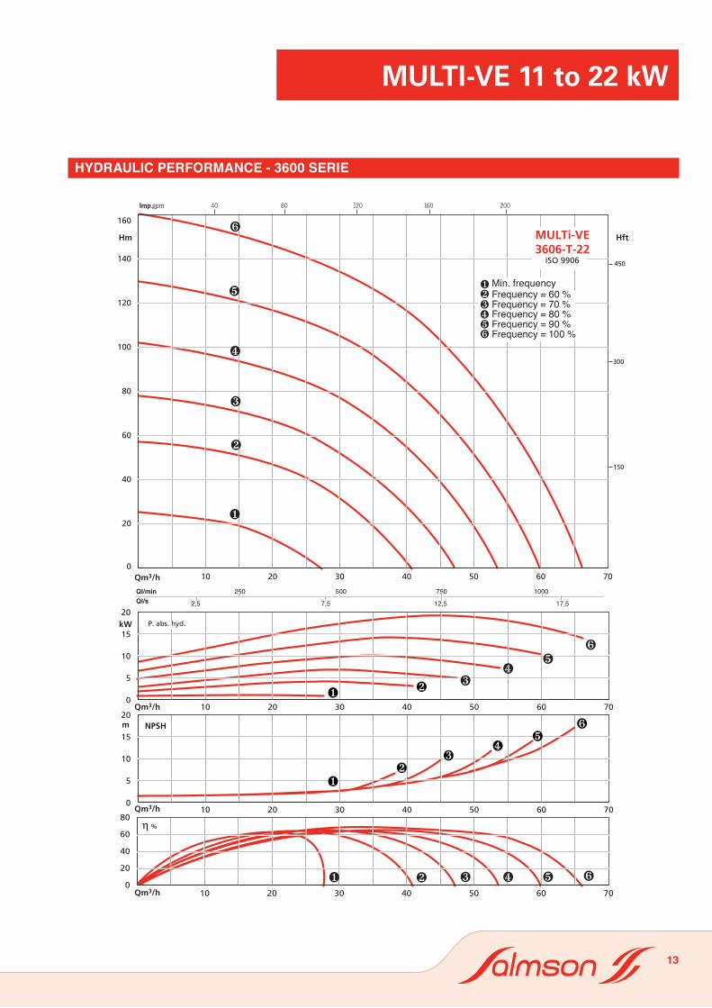
��
��
�
�
�
�
η %
MULTi-VE 11 to 22 kW
13
HYDRAULIC PERFORMANCE - 3600 SERIE
Min. frequencyFrequency = 60 %Frequency = 70 %Frequency = 80 %Frequency = 90 %Frequency = 100 %

Imp.gpm
MULTi-VE 11 to 22 kW
14
Min. frequencyFrequency = 60 %Frequency = 70 %Frequency = 80 %Frequency = 90 %Frequency = 100 %
HYDRAULIC PERFORMANCE - 3600 SERIE

Imp.gpm
MULTi-VE 11 to 22 kW
15
Min. frequencyFrequency = 60 %Frequency = 70 %Frequency = 80 %Frequency = 90 %Frequency = 100 %
HYDRAULIC PERFORMANCE - 6000 SERIE

Imp.gpm
MULTi-VE 11 to 22 kW
16
HYDRAULIC PERFORMANCE - 6000 SERIE
Min. frequencyFrequency = 60 %Frequency = 70 %Frequency = 80 %Frequency = 90 %Frequency = 100 %
Imp.gpm
MULTi-VE 11 to 22 kW
17
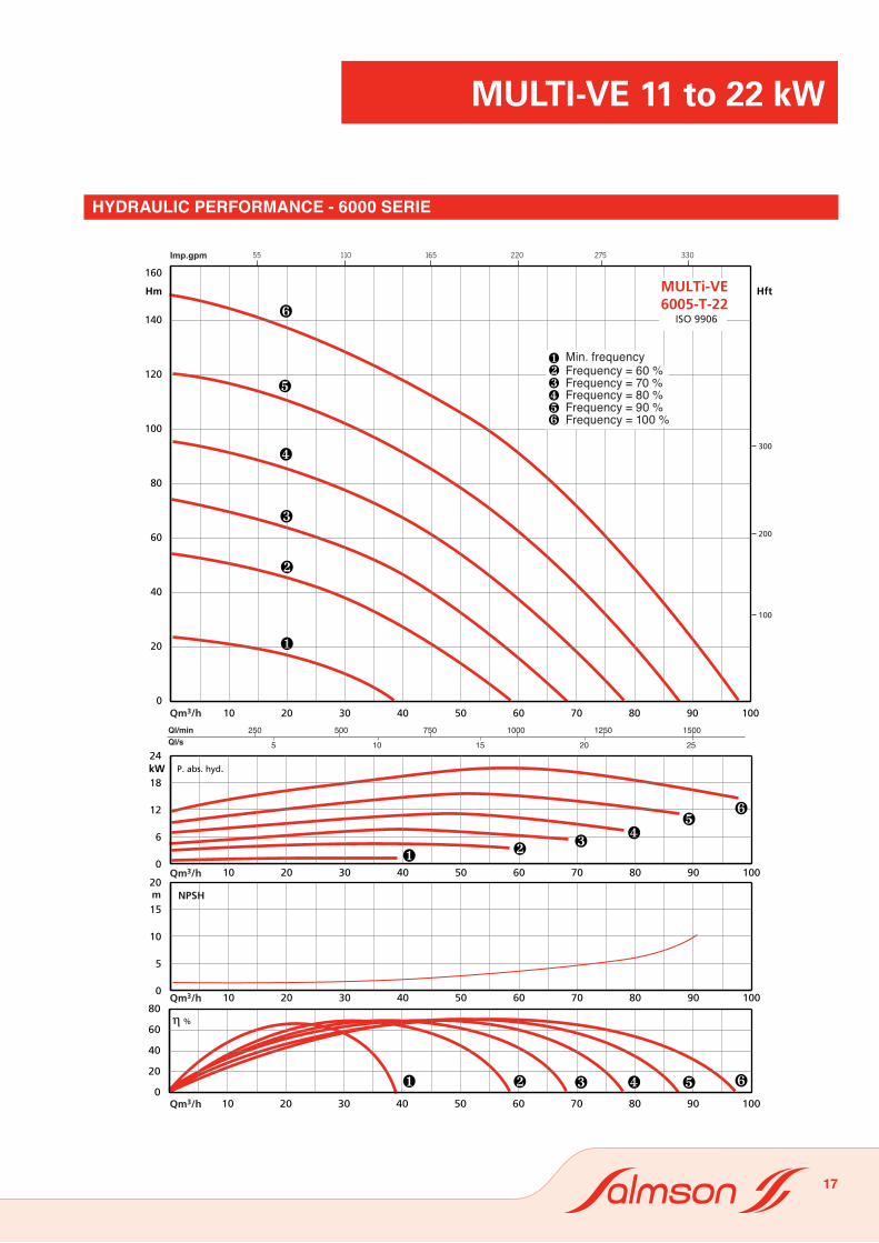
HYDRAULIC PERFORMANCE - 6000 SERIE
Min. frequencyFrequency = 60 %Frequency = 70 %Frequency = 80 %Frequency = 90 %Frequency = 100 %

0 0
50
100
105
5
10
15
20
25
30
35
40
45
50
0
0 100 200 300 400
0
0 10 20 30
500 1000 1500 200020 40 60 80 100 120
0 20 40 60 80 100 120
0 20 40 60 80 100 120
0
2
4
6
8
010203040506070
0
5
10
15
20
N.P.S.H
100%
90%
80%
70%
60%
Fr Mini
N.P
.S.H
(mC
L)
MULTI-VE8002 -T - 11
ISO 9906
HmImp.gpm
H ft
PkW
Qm3/h
Qm3/h
Qm3/h
Ql/min
Ql/s
η%
MULTi-VE 11 to 22 kW
18
HYDRAULIC PERFORMANCE - 8000 SERIE
Min. frequency

0
5
10
15
20
25
30
35
40
45
50
55
60
65
70
0
0 10 20 30 40
0 50 100 150 200
0 1 2 3
20 40 60 80 100 120
0 20 40 60 80 100 120
0 20 40 60 80 100 120
02468
1012
010203040506070
0
5
10
15
20
N.P.S.H N.P
.S.H
(m
CL)
100%
90%
80%
70%
60%
Fr Mini
MULTI-VE7003/1 -T - 11
ISO 9906
HmImp.gpm
H ft
PkW
Qm3/h
Qm3/h
Qm3/h
Ql/min
Ql/s
η%
0 0
100
200
5
10
15
20
25
30
35
40
45
50
55
60
65
70
0
0 10 20 30 40
0 50 100 150 200
0 1 2 3
20 40 60 80 100 120
0 20 40 60 80 100 120
0 20 40 60 80 100 120
02468
1012
010203040506070
0
5
10
15
20
N.P.S.H N.P
.S.H
(m
CL)
100%
90%
80%
70%
60%
Fr Mini
MULTI-VE8003/1 -T - 15
ISO 9906
HmImp.gpm
H ft
PkW
Qm3/h
Qm3/h
Qm3/h
Ql/min
Ql/s
η%
MULTi-VE 11 to 22 kW
19
HYDRAULIC PERFORMANCE - 8000 SERIE
Min. frequency

0 0
100
200
300
10
20
30
40
50
60
70
80
90
0
0
0
20 40 60 80 100 120
0 20 30 40 50 60 70
0 20 30 40 50 60 70
0
4
8
12
01020304050607080
0
5
10
15
20
N.P.S.H N.P
.S.H
(m
CL)
100%
90%
80%
70%
60%
Fr Mini
0 10 20 30 40
50 100 150 200
1 2 3
0 0
100
200
300
10
20
30
40
50
60
70
80
90
0
0
0
20 40 60 80 100 120
0 20 30 40 50 60 70
0 20 30 40 50 60 70
0
4
8
12
01020304050607080
0
5
10
15
20
N.P.S.H N.P
.S.H
(m
CL)
100%
90%
80%
70%
60%
Fr Mini
0 10 20 30 40
50 100 150 200
1 2 3
MULTI-VE8004/2 -T - 18,5
ISO 9906
HmImp.gpm
H ft
PkW
Qm3/h
Qm3/h
Qm3/h
Ql/min
Ql/s
η%
MULTi-VE 11 to 22 kW
20
HYDRAULIC PERFORMANCE - 8000 SERIE

0
10
20
30
40
50
60
70
80
90
100
0
4
8
12
16
0
0 100 200 300 400
0 500 1000 1500 2000
0 10 20 30
20 40 60 80 100 120
0 20 40 60 80 100 120
0 20 40 60 80 100 1200
10203040506070
0
5
10
15
20
N.P.S.H N.P
.S.H
(m
CL)
100%
90%
80%
70%
60%
Fr Mini
MULTI-VE8004 -T - 22
ISO 9906
HmImp.gpm
H ft
PkW
Qm3/h
Qm3/h
Qm3/h
Ql/min
Ql/s
η%
MULTi-VE 11 to 22 kW
21
HYDRAULIC PERFORMANCE - 8000 SERIE
Min. frequency

MULTI-VE100 01 -T - 11
ISO 9906
HmImp.gpm
H ft
PkW
Qm3/h
Qm3/h
Qm3/h
Ql/min
Ql/s
η%
0
5
10
15
20
25
30
0
0 10 20 30 40 50 60
0
0 1 2 3 4
50 100 150 200 250
20 40 60 80 100 120 140 160
0 20 40 60 80 100 120 140 160
0 20 40 60 80 100 120 140 160
0
2
4
6
8
010203040506070
0
5
10
15
20
25
30
N.P.S.H N.P
.S.H
(mC
L)
100%
90%
80%
70%
60%
Fr Mini
0 0
50
100
5
10
15
20
25
30
0
0 10 20 30 40 50 60
0
0 1 2 3 4
50 100 150 200 250
20 40 60 80 100 120 140 160
0 20 40 60 80 100 120 140 160
0 20 40 60 80 100 120 140 160
0
2
4
6
8
010203040506070
0
5
10
15
20
25
30
N.P.S.H N.P
.S.H
(mC
L)
100%
90%
80%
70%
60%
Fr Mini
MULTI-VE10001 -T - 11
ISO 9906
HmImp.gpm
H ft
PkW
Qm3/h
Qm3/h
Qm3/h
Ql/min
Ql/s
η%
MULTi-VE 11 to 22 kW
22
HYDRAULIC PERFORMANCES - 100 00 SERIE
Min. frequency

0 0
50
100
150
150
10
20
30
40
50
0
0 500 1000 1500 2000 2500
0
0 100 200 300 400 500 600
10 20 30 40
20 40 60 80 100 120 140 160
0 20 40 60 80 100 120 140 160
0 20 40 60 80 100 120 140 160
0
4
8
12
010203040506070
0
5
10
15
20
25
30
N.P.S.H
ISO 9906
100%
90%
80%
70%
60%
Fr Mini
0 0
50
100
150
150
10
20
30
40
50
0
0 500 1000 1500 2000 2500
0
0 100 200 300 400 500 600
10 20 30 40
20 40 60 80 100 120 140 160
0 20 40 60 80 100 120 140 160
0 20 40 60 80 100 120 140 160
0
4
8
12
010203040506070
0
5
10
15
20
25
30
N.P.S.H
ISO 9906
100%
90%
80%
70%
60%
Fr Mini
MULTI-VE10002/1 -T - 15
ISO 9906
HmImp.gpm
H ft
PkW
Qm3/h
Qm3/h
Qm3/h
Ql/min
Ql/s
η%
MULTi-VE 11 to 22 kW
23
HYDRAULIC PERFORMANCES - 100 00 SERIE
Min. frequency

0
5
10
15
20
25
30
35
40
45
50
55
60
00
0 100 200 300 400 500 600
500 1000 1500 2000 2500
0 10 20 30 40
20 40 60 80 100 120 140 160
0
0 20 40 60 80 100 120 140 160
0
0 20 40 60 80 100 120 140 160
0
4
8
12
010203040506070
0
5
10
15
20
25
30
N.P.S.H
100%
90%
80%
70%
60%
Fr Mini
0 0
50
100
150
200
5
10
15
20
25
30
35
40
45
50
55
60
00
0 100 200 300 400 500 600
500 1000 1500 2000 2500
0 10 20 30 40
20 40 60 80 100 120 140 160
0
0 20 40 60 80 100 120 140 160
0
0 20 40 60 80 100 120 140 160
0
4
8
12
010203040506070
0
5
10
15
20
25
30
N.P.S.H
100%
90%
80%
70%
60%
Fr Mini
MULTI-VE10002 -T - 18,5
ISO 9906
HmImp.gpm
H ft
PkW
Qm3/h
Qm3/h
Qm3/h
Ql/min
Ql/s
η%
MULTi-VE 11 to 22 kW
24
HYDRAULIC PERFORMANCES - 100 00 SERIE
Min. frequency

0 0
100
200
10
20
30
40
50
60
70
0 20 40 60 80 100 120 140 160
0 20 40 60 80 100 120 140 160
0 20 40 60 80 100 120 140 160
0
4
8
12
16
01020304050607080
0
5
10
15
20
25
30
N.P.S.H
ISO 9906
100%
90%
80%
70%
60%
Fr Mini
0
0 100 200 300 400 500 600
500 1000 1500 2000 2500
0 10 20 30 40
0
0 100 200 300 400 500 600
500 1000 1500 2000 2500
0 10 20 30 40
MULTI-VE10003/2 -T - 22
ISO 9906
HmImp.gpm
H ft
PkW
Qm3/h
Qm3/h
Qm3/h
Ql/min
Ql/s
η%
MULTi-VE 11 to 22 kW
25
HYDRAULIC PERFORMANCES - 100 00 SERIE
Min. frequency

Référence Commande
moteur pompeFréq. T. In. Fréq. T. In. Fréq. T. In. p2
Car. moteur
Bride moteur
H h2 Øm X Masse kg
PN Hz V A Hz V A Hz V A kW mm mm mm mm sans emballage
avec emballage
MULTi-VE 1806..T4/2 16 50 400 19,3 60 380 20 60 440 17,5 11 160 FF300 1032 582,5 258 335 186,5 196,5MULTi-VE 1806...T4/2 25 50 400 19,3 60 380 20 60 440 17,5 11 160 FF300 1032 582,5 258 335 186,5 196,5MULTi-VE 1808...T4/2 25 50 400 27,8 60 380 26,1 60 440 22,5 15 160 FF300 1112,5 651,5 313 365 208,5 218,5MULTi-VE 1810...T4/2 25 50 400 31,9 60 380 33,4 60 440 28,9 18,5 160 FF300 1219,5 720,5 313 350 254,5 264,5
seRie Pression de service maxi Moteur 2 pôles Brides Aspiration/Refoulement
MULTI-VE 1800
16 bar •
DN 50
25 bar •
DN 50
130
4 x ø14
215
X
ASP REF
M
H
h2
ø125
ø65
4 x ø18
20
90
252300
190
BOUTON DE PURGE
BOUTON DE VIDANGE
PE2
PE1
MULTi-VE 11 to 22 kW
26
eLeCtRiCaL Data anD Dimensions - 1800 seRie • PN 16/PN 25 (8”)
seRie Service pressure max. 2 pole motor Flanges Suction / Discharge
VENTING PLUG
SUC. DISC.
DRAINING PLUG
Order référence
motor pumpFreq. T. In. Freq. T. In. Freq. T. In. p2
Casing motor
Flange motor
H h2 Øm X Mass kg
NP Hz V A Hz V A Hz V A kW mm mm mm mm without packaging
with packaging

Référence Commande
moteur pompeFréq. T. In. Fréq. T. In. Fréq. T. In. p2
Car. moteur
Bride moteur
H h2 Øm X Masse kg
PN Hz V A Hz V A Hz V A kW mm mm mm mm sans emballage
avec emballage
MULTi-VE 3603..T4/2 16 50 400 18,6 60 380 19,4 60 440 16,7 11 160 FF300 985,5 536 258 335 186,5 196,5MULTi-VE 3604...T4/2 16 50 400 24,4 60 380 25,8 60 440 22,3 15 160 FF300 1043 582 313 365 206 216MULTi-VE 3605...T4/2 16 50 400 30,3 60 380 31,8 60 440 29,6 18,5 160 FF300 1173 674 313 350 256,5 266,5MULTi-VE 3603...T4/2 25 50 400 18,6 60 380 19,4 60 440 16,7 11 160 FF300 1000,5 551 258 335 193,5 203,5MULTi-VE 3604...T4/2 25 50 400 24,4 60 380 25,8 60 440 22,3 15 160 FF300 1058 597 313 365 213 223MULTi-VE 3605...T4/2 25 50 400 30,3 60 380 31,8 60 440 29,6 18,5 160 FF300 1188 689 313 350 262 272MULTi-VE 3606...T4/2 25 50 400 35,9 60 380 37,5 60 440 32,6 22 180 FF300 1214 689 351 365 299,5 309,5MULTi-VE 3607...T4/2 25 50 400 40,8 60 380 42,9 60 440 38 22 180 FF300 1357 832 351 365 320 330
seRie Pression de service maxi Moteur 2 pôles Brides Aspiration/Refoulement
MULTI-VE 3600
16 bar •
DN 65
25 bar •
DN 65
ø1454 x ø18
ø80
235320235
35
h2
H
105
BOUCHON DE VIDANGE
BOUCHON DE PURGE
ASP. REF.
195
195
4 x ø14
X
M
PE2
PE1
BOUCHON DE VIDANGE
BOUCHON DE PURGE
H
h2
8 x ø18ø145
ø80
260320260
35
120
ASP. REF.
M
220
220
4 x ø14
XPE2
PE1
MULTi-VE 11 to 22 kW
27
eLeCtRiCaL Data anD Dimensions - 3600 seRie
seRie Service pressure max. 2 pole motor Flanges Suction / Discharge
VENTING PLUG VENTING PLUG
SUC. SUC.DISC. DISC.
DRAINING PLUG DRAINING PLUG
Order référence
motor pumpFreq. T. In. Freq. T. In. Freq. T. In. p2
Casing motor
Flange motor
H h2 Øm X Mass kg
NP Hz V A Hz V A Hz V A kW mm mm mm mm without packaging
with packaging

Référence Commande
moteur pompeFréq. T. In. Fréq. T. In. Fréq. T. In. p2
Car. moteur
Bride moteur
H h2 Øm X Masse kg
PN Hz V A Hz V A Hz V A kW mm mm mm mm sans emballage
avec emballage
MULTi-VE 6003..T4/2 16 50 400 25 60 380 26,4 60 440 22,7 15 180 FF300 1044 583 313 365 210 220MULTi-VE 6004...T4/2 16 50 400 32,7 60 380 34,1 60 440 29,3 18,5 160 FF300 1143 644 313 350 256,5 266,5MULTi-VE 6005...T4/2 16 50 400 38,9 60 380 41,4 60 440 35,5 22 180 FF300 1292 767 351 365 292,5 302,5MULTi-VE 6003...T4/2 25 50 400 25 60 380 26,4 60 440 22,7 15 160 FF300 1044 583 313 365 210 220MULTi-VE 6004...T4/2 25 50 400 32,7 60 380 34,1 60 440 29,3 18,5 160 FF300 1143 644 313 350 256,5 266,5
MULTi-VE 6005...T4/2 25 50 400 38,9 60 380 41,4 60 440 35,5 22 180 FF300 1292 767 351 365 292,5 302,5
seRie Pression de service maxi Moteur 2 pôles Brides Aspiration/Refoulement
MULTI-VE 6000
16 bar •
DN 80
25 bar •
DN 80
BOUCHON DE PURGE
BOUCHON DE VIDANGE
ASP. REF.
220
220
4 x ø14
H
h2
ø160
ø80
260 260
320
30
105
8 x ø18
M
PE2
PE1
MULTi-VE 11 to 22 kW
28
eLeCtRiCaL Data anD Dimensions - 6000 seRie • PN 16/PN 25 (8”)
VENTING PLUG
SUC. DISC.
DRAINING PLUG
seRie Service pressure max. 2 pole motor Flanges Suction / Discharge
Order référence
motor pumpFreq. T. In. Freq. T. In. Freq. T. In. p2
Casing motor
Flange motor
H h2 Øm X Mass kg
NP Hz V A Hz V A Hz V A kW mm mm mm mm without packaging
with packaging

seRie Pression de service maxi Moteur 2 pôles Brides Aspiration/Refoulement
MULTI-VE 8000
16 bar •
DN 100
25 bar •
DN 100
Référence commandeFréq. T. In. Fréq. T. In. p2
Car.moteur
Bridemoteur
H h2 Øm X Masse en kg
PN Hz V A Hz V A KW mm mm mm mm sans emb.
avec emb.
MULTI-VE8002-OGE-T4/2 16 50 400 20,3 60 380 21,2 11,00 160M2 FF300 1206,5 757 258 335 213,5 228,5MULTI-VE8003/1-OGE-T4/2 16 50 400 27,4 60 380 28,4 15,00 160MX2 / L2 FF300 1303 842 313 365 246 261MULTI-VE8004/2-OGE-T4/2 16 50 400 32,2 60 380 33,9 18,50 160MX2 / L2 FF300 1426 927 313 350 281 296MULTI-VE8004-OGE-T4/2 16 50 400 38,5 60 380 40,6 22,00 180M2 FF300 1452 927 351 365 312 327MULTI-VE8002-FGE-T4/2 25 50 400 20,3 60 380 21,2 11,00 160M2 FF300 1206,5 757 258 335 213,5 228,5MULTI-VE8003/1-FGE-T4/2 25 50 400 27,4 60 380 28,4 15,00 160MX2 / L2 FF300 1303 842 313 365 246 261MULTI-VE8004/2-FGE-T4/2 25 50 400 32,2 60 380 33,9 18,50 160MX2 / L2 FF300 1426 927 313 350 281 296MULTI-VE8004-FGE-T4/2 25 50 400 38,5 60 380 40,6 22,00 180M2 FF300 1452 927 351 365 312 327
MULTi-VE 11 to 22 kW
29
eLeCtRiCaL Data anD Dimensions - 8000 seRie • PN 16/PN 25 (10”)
SUC. DISC.
seRie Service pressure max. 2 pole motor Flanges Suction / Discharge
Order référenceFreq. T. In. Freq. T. In. p2
Casing motor Flange motor
H h2 Øm X Mass kg
NP Hz V A Hz V A KW mm mm mm mm without pack.
with pack.

Référence commandeFréq. T. In. Fréq. T. In. p2
Car.moteur
Bridemoteur
H h2 Øm X Masse en kg
PN Hz V A Hz V A KW mm mm mm mm sans emb.
avec emb.
MULTI-VE10001-OGE-T4/2 16 50 400 16,5 60 380 17,3 11,00 160M2 FF300 1134,5 685 258 335 210 225MULTI-VE10002/1-OGE-T4/2 16 50 400 26,3 60 380 28 15,00 160MX2 / L2 FF300 1244 783 313 365 244 259MULTI-VE10002-OGE-T4/2 16 50 400 30,1 60 380 31,8 18,50 160MX2 / L2 FF300 1282 783 313 350 275 290MULTI-VE10003/2-OGE-T4/2 16 50 400 34,8 60 380 37,3 22,00 180M2 FF300 1406 881 351 365 310,5 325,5MULTI-VE10001-FGE-T4/2 25 50 400 16,5 60 380 17,3 11,00 160M2 FF300 1134,5 685 258 335 210 225MULTI-VE10002/1-FGE-T4/2 25 50 400 26,3 60 380 28 15,00 160MX2 / L2 FF300 1244 783 313 365 244 259MULTI-VE10002-FGE-T4/2 25 50 400 30,1 60 380 31,8 18,50 160MX2 / L2 FF300 1282 783 313 350 275 290MULTI-VE10003/2-FGE-T4/2 25 50 400 34,8 60 380 37,3 22,00 180M2 FF300 1406 881 351 365 310,5 325,5
seRie Pression de service maxi Moteur 2 pôles Brides Aspiration/Refoulement
MULTI-VE 100.00
16 bar •
DN 100
25 bar •
DN 100
MULTi-VE 11 to 22 kW
30
FeatuResAssembly- Installation in an easily-reached place. Install a lifting hook in line with the pump for easy disassembly.- Assembly on concrete block > 10 cm high with attachment by anchor bolts. An insulating material is required under the concrete base to prevent the transmitting of noises and vibrations.- The installation should protect the pump against the bad weather and freezing (not of direct exposure to the rain or the sun).
Packaging- Wooden crate;- Supplied with seals and bolts, without coun-terflanges (optional).
aCCessoRies- Isolating valves- Counter-flanges- Anti-vibration sleeves- Bladder vessel- Non-return valves- Foot valve strainer- Water shortage protection
ELECTRICAL DATA AND DIMENSIONS - 100.00 SERIE• PN 16/PN 25 (10”)
seRie Service pressure max. 2 pole motor Flanges Suction / Discharge
Order référenceFreq. T. In. Freq. T. In. p2
Casing motor Flange motor
H h2 Øm X Mass kg
NP Hz V A Hz V A KW mm mm mm mm without pack.
with pack.
SUC. DISC.