91-019erps.spacegrant.org/uploads/images/images/iepc_article...91-019 combining equation (4) with...
TRANSCRIPT

91-019
A Review of the Theory of Self-Field MPD Thrusters
J. L. Lawless'Space Power Inc.
San Jose, Ca 94134and
V. V. Subramaniam'Department of Mechanical Engineering
The Ohio State UniversityColumbus, Ohio 43210-1107
Abstract
A great amount of research has been performed in self-fieldMagnetoplasmadynamic (MPD) thruster research during the past decade. In
contrast to previous years, activity in the theoretical and modelling areashave increased. This paper will review the developments in the theory ofself-field MPD thrusters, concentrating mainly on one-dimensional and
quasi one-dimensional theories, for which exact or approximate solutionscan be obtained.
Nomenclature a Ionization fractionEi Ionization potential
a Frozen speed of sound TH Heavy particle viscosityB Magnetic inductionCe Mean thermal speed of electrons K Ratio of magnetic induction at inlet to
the magnetic induction at the chokingCH Mean thermal speed of heavy particles pointE Electric field 9o permeability of free spaceh Enthalpy per unit mass p Mass densityH Channel height Y Electrical conductivityj Current densityJ Total current i Subscript denoting inlet quantityk Boltzmann's constant e Subscript denoting exit quantityL Channel length
m Mass flow rate Superscript denoting quantity evaluated
mA Atomic mass at the sonic or choking point
me Electron mass I. Introduction
ne Electron or charged particle numberensty During the past ten years, there has been a
S Pressure great deal of activity in self-field
QAA Total momentum transfer cross section magnetoplasmadynamic (MPD) thruster
A research. This paper will attempt tofor atom-atom collisions summarize the developments in the theory of
qA Total momentum transfer cross section these thrusters and compare theory to
for ion-atom collisions available experiments. Models are now
qi Total momentum transfer cross section capable of predicting I-V curves from first
for ion-ion collisions principles. The conditions under which
T Temperature electrodes erode are beginning to be
Te Electron temperature understood. Quantitative prediction of the
e destructive "onset" phenomenon also appearsTh Thrust to be possible now.TH Heacy particle temperature
u Axial component of velocity Early work in the field of MPD thrusters
W Channel width has been summarized by Jahn[1]. The
x Coordinate along channel technology of MPD thrusters has been
'Member, AIAA
' Member, AIAA
91-019
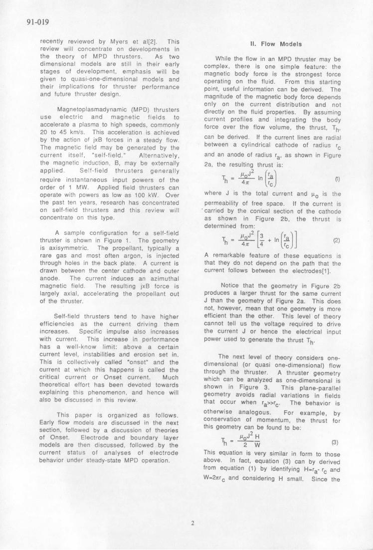
recently reviewed by Myers et al[2]. This II. Flow Modelsreview will concentrate on developments inthe theory of MPD thrusters. As two While the flow in an MPD thruster may bedimensional models are still in their early complex, there is one simple feature: thestages of development, emphasis will be magnetic body force is the strongest forcegiven to quasi-one-dimensional models and operating on the fluid. From this startingtheir implications for thruster performance point, useful information can be derived. Theand future thruster design. magnitude of the magnetic body force depends
only on the current distribution and notMagnetoplasmadynamic (MPD) thrusters directly on the fluid properties. By assuming
use electric and magnetic fields to current profiles and integrating the bodyaccelerate a plasma to high speeds, commonly force over the flow volume, the thrust, Th,20 to 45 km/s. This acceleration is achievedby the action of jxB forces in a steady flow. can be eied f the current lines are radialThe magnetic field may be generated by the between a cylindrical cathode of radius rccurrent itself, "self-field." Alternatively, and an anode of radius ra, as shown in Figurethe magnetic induction, B, may be externally 2a, the resulting thrust is:applied. Self-field thrusters generally 2 (r
require instantaneous input powers of the Th = 4 l rcn \
order of 1 MW. Applied field thrusters canoperate with powers as low as 100 kW. Over where J is the total current and po is thethe past ten years, research has concentrated permeability of free space. If the current ison self-field thrusters and this review will carried by the conical section of the cathodeconcentrate on this type. as shown in Figure 2b, the thrust is
determined from:A sample configuration for a self-field P J2 3 l )
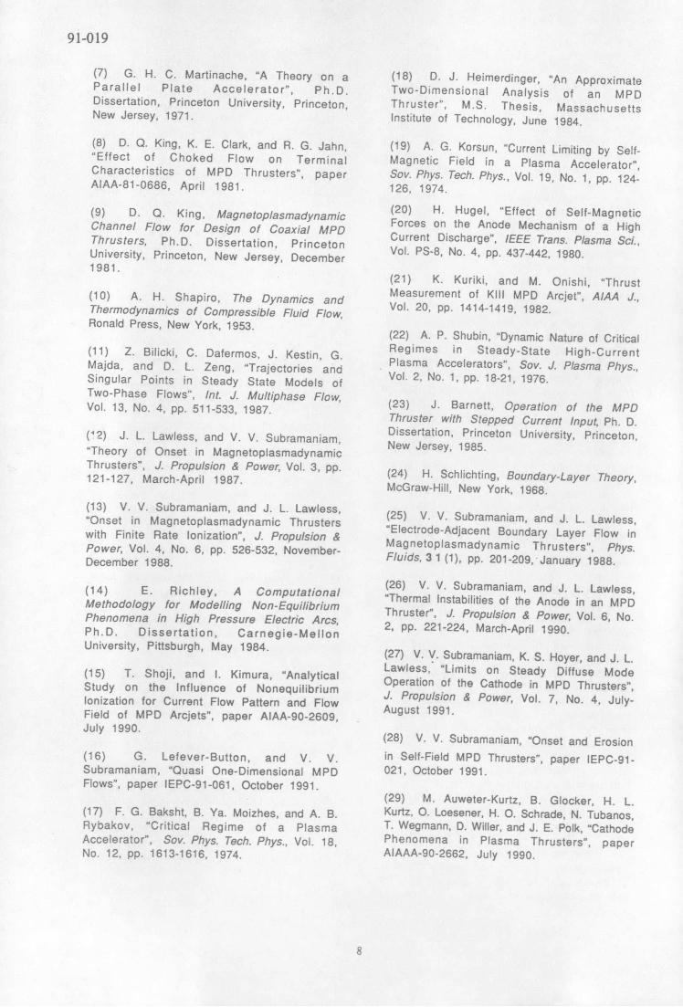
thruster is shown in Figure 1. The geometry Th = 4 + In - (2)is axisymmetric. The propellant, typically a rcrare gas and most often argon, is injected A remarkable feature of these equations isthrough holes in the back plate. A current is that they do not depend on the path that thedrawn between the center cathode and outer current follows between the electrodes[1].anode. The current induces an azimuthalmagnetic field. The resulting jxB force is Notice that the geometry in Figure 2blargely axial, accelerating the propellant out produces a larger thrust for the same currentof the thruster. J than the geometry of Figure 2a. This does
not, however, mean that one geometry is moreSelf-field thrusters tend to have higher efficient than the other. This level of theory
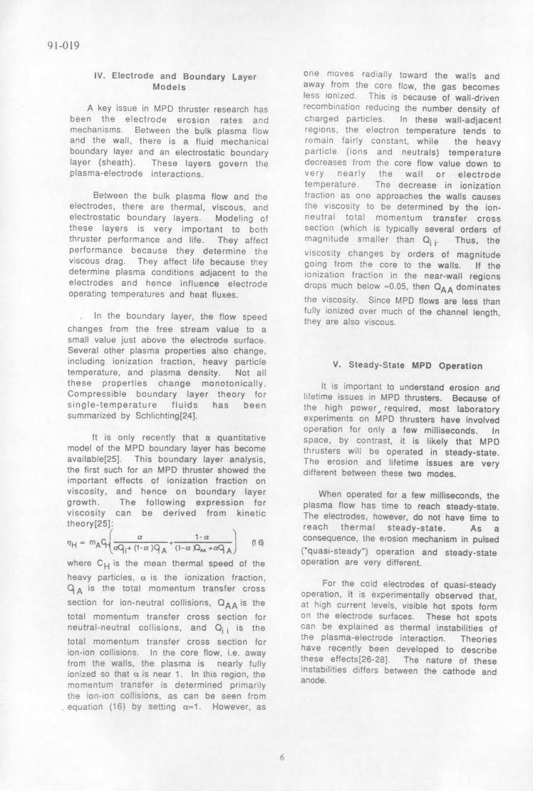
efficiencies as the current driving them cannot tell us the voltage required to driveincreases. Specific impulse also increases the current J or hence the electrical inputwith current. This increase in performance power used to generate the thrust Th.has a well-know limit: above a certaincurrent level, instabilities and erosion set in. The next level of theory considers one-This is collectively called "onset" and the dimensional (or quasi one-dimensional) flowcurrent at which this happens is called the through the thruster. A thruster geometrycritical current or Onset current. Much which can be analyzed as one-dimensional istheoretical effort has been devoted towards shown in Figure 3. This plane-parallelexplaining this phenomenon, and hence will geometry avoids radial variations in fieldsalso be discussed in this review, that occur when ra>>rc. The behavior is
otherwise analogous. For example, byThis paper is organized as follows. otherwise analogous. For example, byconservation of momentum, the thrust for
Early flow models are discussed in the next conservation of momentum, the thrust for
section, followed by a discussion of theories this geometry c be found to be:
of Onset. Electrode and boundary layer T = oJ Hmodels are then discussed, followed by the h 2 W (3)current status of analyses of electrode This equation is very similar in form to thosebehavior under steady-state MPD operation, above. In fact, equation (3) can by derived
from equation (1) by identifying H=ra- rc andW= 2 nrc and considering H small. Since the
2

91-019
thrust Th is the product of the mass flow number of supersonic tlow. Since themagnitude of the ohmic heating generally
rate, m, and the exhaust speed,ue, the above greatly exceeds the stagnation enthalpy of
equation also determines exhaust speed: the injected propellant, the flow is quickly2 driven to Mach 1. In order to accelerate again
ue = (4) to supersonic speeds, the choking conditione 2m W must still be met. The case of supersonic
For the case of an applied field thruster, propellant injection was extensively studied
the gas dynamics of the channel flow were by King[9].
first studied in 1958 by Sears andResler[3,4], Their study mapped the various King recognized that this model had
regions of operation including such important important implications for thruster design.
effects as MPD choking. Further discussion of This led to the development of the King
this theory can be found textbooks[5,6]. anode[8].
In the 1970's, attention shifted to self- To clarify the relationship between this
field thrusters. Self-field thrusters offered theory and earlier work, the equations (1)-
engineering simplicity by not requiring large (3), (4) for thrust can be derived from the
magnets. Inspired by a Ph.D. thesis by momentum equation given in Table I by
Martinache[7], King[8,9], developed a model of neglecting pressure.
self-field thrusters that could successfullyThere is another restriction on the
compare to experiment. In King's model, the There is another restriction on thethruster is modeled as a one-dimensional electric field. From consideration of Ohm'sthruster is modeled as a one-dimensional conditions, it is
flow subjected to ohmic heating and the law under usual MPD thruster conditions, it isflow subjected to ohmic heating and the found that the back-EMF must never exceedmagnetic body force (See Table I). the applied, electric field, E:
uB E (6)To understand the flow, it is necessary
to know how the various phenomena affect This restriction does not replace the chokingto know how the various phenomena affect .
he ow's Mach number. This is summarized condition. Rather, it must be obeyed in
in Table II and is not always intuitive[10]. At addition to the choking condition equation
the inlet of a MPD thruster, ohmic heating is (5). This presents an interesting and
dominant and this drives the flow towards important issue. Let us combine the
the sonic point (M=1). As the flow speed inequality (6) with the choking condition:
increases, the magnetic body force becomes uB 5-a* B* (7)
increasingly important. Under exactly theright condition, ohmic heating lifts the Mach Somewhere in the middle region of the
number to 1 and the magnetic body force then thruster, the product uB reaches a maximum.
drives the Mach number still higher. The This region is observed experimentally as a
condition under which this happens is called region of low current density. Let us call the
the choking condition, and a rigorous values of u and B at this point ur, and Bm ,
mathematical discussion of this condition respectively. Now, rewrite inequality (7) as:
can be found in Ref.[11]. For an ideal m 5a* (8)monatomic gas, the choking condition is: 2 B
E = 5 a* B* (5) The magnetic induction at the choking point,2 B*, is within 10% of the magnetic induction
where a is the speed of sound, E is the at the thruster inlet. The magnetic induction,electric field, B is the magnetic induction and Bm, where the back-EMF is a maximum isthe superscript * indicates that these arethe superscript * indicates that these are usually 0.6 to 0.7 times the value at the inlet.evaluated at the choking point. This condition Thus, their ratio can be approximated as 1.5.must be satisfied or the flow cannot Substituting in this value:accelerate from subsonic to supersonic um 3.75a* (9)speeds. This generally happens far upstream
in the thruster as shown in Figure 1. The right-hand side above is fairly constant.a* is determined by the temperature at the
One might naively assume that, if the flow choking point and plasma temperatures are
is introduced into the thruster known to vary little. The left-hand side
supersonically, then the choking condition varies strongly with current. From equation
would be irrelevant. This is generally not the (4), the exhaust speed scales as J2/m. Thus,
case. Immediately after the flow is injected, equation (9) appears to place a limit on J2 /m.it is still subjected to strong ohmic heating. Let us estimate um as 2/3 of ue. ThenFrom Table II, ohmic heating lowers the Mach
3

91-019
combining equation (4) with equation (9) field below the peak values that thegives: equilibrium theory would allow. For a
2 o 2 H < 3.75a* monatomic gas with finite rate ionization,3 2 W - 0) the choking condition is:
Rearranging this gives: E = 5a* B* + p a ei d(4)S Wa 2 j m A dx = x*
m 1.25- (1 where a is the ionization fraction, ei is the
This equation expresses the restriction on ionization potential, mA is the atomic mass,
2/ m that comes from combining the choking and j* is the current density evaluated at thecondition, equation (5), with the limit on choking point. It is apparent that theback-EMF, uB5E. The above derivations ionization rate at the choking point raises theincluded several approximations. If the electric field above the value it would haveequations on Table I are solved exactly, the for an ideal monatomic gas. This allows theresult is: thruster to operate at higher J2 /m than the
52 W8 a* ideal gas theory would permit. How muchm 8.52H (12) higher depends on the ionization fraction and
r is io ic i ion temperature at the choking point. Towhere i is the ratio of the magnetic induction determine this currently requires a fullat the inlet to the magnetic induction at the numerical model. With such a model, it haschoking point. This typically has a value of been possible to quantitatively predict onsetabout 1.1R9]. This explanation of onset first currents, as shown in Figure 5 and Figureappeared in Ref[12]. 6[13].
It should be mentioned that the role of For simplicity, most of the models aboveinlet flow conditions in altering the have assumed a one-temperature plasma. Theoccurrence of back-EMF onset is contained plasmas in MPD thrusters are more accuratelyentirely in the K factor. This quantity is described by two-temperatures. A fairlyrestricted to a small range about 1.1. Inlet complete simulation of a two-temperatureconditions are extensively discussed in Ref. MPD thruster with ionizing argon has been
[9. performed by Richley[14]. The simulationwas capable of modeling fully unsteady flow.The above discussion was based on the A sample temperature profile is shown inideal gas choking condition, equation (5). For Figure 7.
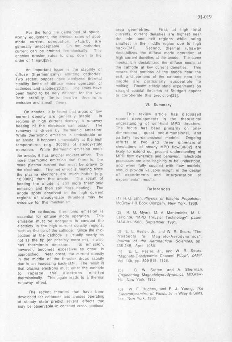
quantitative results, non-ideal effects mustbe considered, principally ionization. If one Shoji and Kimura have developed a theoryconsiders equilibrium flow, the choking of two-temperature flow in MPDcondition becomes: thrusters[15]. They also extended the model
E = p*- * B* (13) to include dissociating molecular gases andSperformed calculations on hydrogen. As for
The quantity in square brackets is 5/2 for an ionization, nonequilibrium dissociation altersideal monatomic gas. For equilibrium argon, the choking condition, raising the allowedits value is shown in Fig. 4. It is seen that electric field. They restricted their study tothe equilibrium theory and ideal monatomic the region between choking and exit regionsgas theory agree only at low temperatures, and parametrically varied the conditions at<5000K. For higher temperatures, the choking. For fixed thermodynamic conditionsequilibrium theory predicts much higher at the choking point and for fixed totalelectric fields. These higher electric fields current, they varied the mass flow. Theywould have the effect of delaying back-EMF numerically found a minimum mass flow, i.e.onset to larger values of J2 /m . The maximum J2 /m , for which the thruster had a
magnitude of the increase in J2 can be finite length. This is exactly the behaviorestimated by replacincreag 5/2 in 2 /equation (7)be expected from the above discussion of back-with the values given in Fig. 4 and then (7) EMF Onset and choking conditions. This iscontinuing the values givation asFig. 4 and thenbefore the first calculation of this effect in a two-continuing the derivation as beforetemperature model.
Unfortunately, the equilibrium assumption Models of self-field MPD thrusters haveis not accurate. Real gases have finite greatly a dvanced over the past ten years. h a v e
ionization rates and this reduces the electric Beginning with imates for thrust,eginning with simple estimates for thrust,
4

91-019
models are now able to predict detailed reduce the random thermal current density,temperature and speed distributions. The j thermal. At sufficiently high current, themodels described in this section have, required net current density may exceed thehowever, been restricted to quasi one- random thermal current. Under thisdimensional flows. This limits, for example, condition, the anode sheath voltage drop istheir ability to describe flow in the Princeton expected to change signs and become positive"benchmark" thrusters which have an anode in order to help draw more current. Thislip protruding into the flow. They have, effect is sometimes called anode masshowever, quantitatively described flows in starvation.straight channel coaxial thrusters as well asthrusters with the diverging King anode[8,9, This change in sign of the anode sheath13]. More recent comparisons between this voltage drop was analyzed by Baksht,quasi one-dimensional model and Moizhes, and Rybakov in 1974 using a simpleexperimental results at Princeton on the quasi-one-dimensional model[17]. They tookHalf-Scale Flared Anode Thruster (HSFAT) this change in sign as their onset criterion.show excellent agreement as can be seen Several refinements to this model have beenfrom Fig. 8[16]. This suggests that quasi on- made by Heimerdinger[18]. Korsun considereddimensional models may serve as very useful a similar mass starvation effect in a twotools for design and optimization. dimensional model[19]. Hugel measured the
anode sheath voltage drop in a thruster andfound that onset was associated with the
III. More Theories of Onset change in sign[20].
The phenomenon of "onset" has attracted a The reason why a change in sign of thegreat deal of experimental and theoretical anode sheath should cause onset was notinterest. Several theoretical explanations of clear because many discharges operate in aonset have been advanced and more than one stable steady state with anode sheaths ofhave experimental evidence to support them. both signs. Two hypotheses exist to explainIt may be possible that onset does not this. Kuriki and Onishi suggest that when therepresent a single phenomenon but several anode fall is positive, ions accelerated in thephenomena which all occur at high current sheath may produce sputtering[21].levels. The back-EMF theory of onset was Alternatively, Shubin found that anode massdiscussed above because it is an integral part starvation is associated not just with anodeof quasi-one-dimensional MPD flow theory. sheath reversal but also with plasmaSome of the other theories of onset will be instabilities[22]. He suggested that thesediscussed here. instabilities may cause onset.
Several theories focus on plasma If onset were solely due to anode massconditions near the anode. Specifically, starvation, the experimental remedy would beconsider a plasma with electron density ne clear: inject more mass near the anode. This
and mean thermal speed Ce=(8kTe/men) 1 /2. in fact was done as part of a very detailed
The random thermal current density is set of onset experiments performed by
j thermaleneCe/4. If the net current density Barnett[23]. He found that, under someconditions, onset was associated with
between the plasma and the anode is less instabilities near the anode. However, hethan Jthermal, an anode sheath forms with a also found that injecting mass near the anodepotential that discourages the flow of did not prevent the occurrence of onset.electrons to the anode. This potential is a Rather, onset still occurred but wasnegative voltage drop and is observed most of associated with instabilities in other regionsthe time during low current operation of MPD of the thruster. He found that, by controllingthrusters. For high current operation, several mass injection, he could cause the region ofeffects combine to change this condition, instability to move around the thruster fromFirst, for high current operation the current anode to cathode. This appears to indicatedensity is simply higher. Secondly, at high that, while anode mass starvation may be onecurrent, the flow is accelerated to higher onset mechanism, it is certainly not the onlyspeeds and hence lower densities. Thirdly, at onset mechanism.higher currents, the Hall effect becomesstronger and this tends to drive the plasmafrom the anode towards the thrustercenterline. These latter two effects tend to
5
91-019
IV. Electrode and Boundary Layer one moves radially toward the walls andModels away from the core flow, the gas becomes
less ionized. This is because of wall-drivenA key issue in MPD thruster research has recombination reducing the number density of
been the electrode erosion rates and charged particles. In these wall-adjacentmechanisms. Between the bulk plasma flow regions, the electron temperature tends toand the wall, there is a fluid mechanical remain fairly constant, while the heavyboundary layer and an electrostatic boundary particle (ions and neutrals) temperaturelayer (sheath). These layers govern the decreases from the core flow value down toplasma-electrode interactions, very nearly the wall or electrode
temperature. The decrease in ionizationBetween the bulk plasma flow and the fraction as one approaches the walls causes
electrodes, there are thermal, viscous, and the viscosity to be determined by the ion-electrostatic boundary layers. Modeling of neutral total momentum transfer crossthese layers is very important to both section (which is typically several orders ofthruster performance and life. They affect magnitude smaller than Qi i. Thus, theperformance because they determine the viscosity changes by orders of magnitudeviscous drag. They affect life because they going from the core to the walls. If thedetermine plasma conditions adjacent to the ionization fraction in the near-wall regionselectrodes and hence influence electrode drops much below =0.05, then QAA dominatesoperating temperatures and heat fluxes. the viscosity. Since MPD flows are less than
n the boundary layer, the flow speed fully ionized over much of the channel length,In the boundary layer, the flow speed they are also viscous.changes from the free stream value to asmall value just above the electrode surface.Several other plasma properties also change,including ionization fraction, heavy particle V. Steady-State MPD Operationtemperature, and plasma density. Not allthese properties change monotonically. It is important to understand erosion andCompressible boundary layer theory for lifetime issues in MPD thrusters. Because ofsingle-temperature fluids has been the high power required, most laboratorysummarized by Schlichting[24]. experiments on MPD thrusters have involved
operation for only a few milliseconds. InIt is only recently that a quantitative space, by contrast, it is likely that MPD
model of the MPD boundary layer has become thrusters will be operated in steady-state.available[25]. This boundary layer analysis, The erosion and lifetime issues are verythe first such for an MPD thruster showed the different between these two modes.important effects of ionization fraction onviscosity, and hence on boundary layer When operated for a few milliseconds, thegrowth. The following expression for plasma flow has time to reach steady-state.viscosity can be derived from kinetic The electrodes, however, do not have time totheory[25]: reach thermal steady-state. As a
1n = a 1-a 1 consequence, the erosion mechanism in pulsedAH 9 i+(1-a)qA (l-a)Q+q A) ("quasi-steady") operation and steady-state
where CH is the mean thermal speed of the operation are very different.
heavy particles, a is the ionization fraction,qA is the total momentum transfer cross Fo r t h e c o ld electrodes of quasi-steadySoperation, it is experimentally observed that,section for ion-neutral collisions, QAA is the at high current levels, visible hot spots formtotal momentum transfer cross section for on the electrode surfaces. These hot spotsneutral-neutral collisions, and Qii is the can be explained as thermal instabilities of
the plasma-electrode interaction. Theoriestotal momentum transfer cross section for t h e laa-electrode interaction. Theories
ion-ion collisions. In the core flow, i.e. away h a v e rec e n tly b e e n developed to describe
from the walls, the plasma is nearly fully t h e s e effects[26-28]. The nature of these
ionized so that a is near 1. In this region, the instabilities differs between the cathode andanode.
momentum transfer is determined primarilythe ion-ion collisions, as can be seen from
Sequation (16) by setting a-1. However, as
6
91-019
area geometries. First, at high totalFor the long life dema-aed of space- currents, current densities are highest near
worthy equipment, the erosion rates of spot- the inlet and exit regions while beingmode current conduction, >1lg/C, ae smallest in the middle region due to highgenerally unacceptable. On hot cathodes, back-EMF. Second, thermal runawaycurrent can be emitted thermionically. This destabilizes the diffuse mode operation atenables erosion rates to drop down to tne high current densities at the anode. The sameorder of 1 ng/C[29]. mechanism destabilizes the diffuse mode at
the cathode at low current densities. ThisAn important issue is the stability of means that portions of the anode near the
diffuse (thermionically) enmtt ng cathodes.Two recent papers have alyed thermal exit, and portions of the cathode near the
Two recent papers have analyzed thermalmiddle are particularly susceptible to
stability limits of diffuse mide operation of middle are particularly susceptible tos and anos The limits h melting. Recent steady state experiments on
cathodes and anodes[26.2] The limits havebeen fund to be ver d' i fr the two straight coaxial thrusters at Stuttgart appearbeen found to be very difrerit for the two. t cto corroborate this prediction[28].Both stability limits invol/e thermionic r
emission and sheath theoryVI. Summary
On anodes, it is founc that areas of lowThis review article has discussed
current density are gene-ally stable. Inrecent developments in the theoretical
regions of high current density, a runaway recent developments in the theoretical
heating of the electrode i:an occur. The understanding of self-field MPD thrusters.
runaway is driven by thermionic emission. The focus has been primarily on one-
While thermionic emission ;s undesirable on dimensional, quasi one-dimensiona, andpartially two-dimensional models. Ongoingan anode, it happens ^^^^^ a; efforts in two and three dimensionalefforts in two and three dimensional
temperatures (e.g. 3000K) of steady-stateoperation. While thermionic emission coolsmuations of steady MPD fow[3032] are
likely to extend our present understanding ofthe anode, it has another indirect effect. The MPD flow dynamics and behavior. Electrodemore thermionic emission that there is, the processes are also begining to be understood,more plasma current that must be drawn to and when fully coupled with flow models,the electrode. The net effect is heating since should provide valuable insight in the designthe plasma electrons are much hotter (e.g. of experiments and interpretation of10,000K) than the anode The result of experimental results.heating the anode is still more thermionicemission and then still more heating. The Referencesanode spots observed in the high currentregions of steady-state thrusters may be (1) R. G. Jahn, Physics of Electric Propulsion,evidence for this mechanism. McGraw-Hill Book Company, New York, 1968.
On cathodes, thermionic emission is (2) R. M. Myers, M. A. Mantenieks, M. L.essential for diffuse mode operation. This LaPointe, "MPD Thruster Technology", paperemission must be adequate to conduct the AIAA-91-3568, September 1991.electricty in the high current density regions,such as the tip of the cathcde. Since the mid- (3) E. L. Resler, Jr., and W. R. Sears, "Thesection of the cathode is usually nearly as Prospects for Magneto-Aerodynamics",hot as the tip (or possibly more so), it also Journal of the Aeronautical Sciences, pp.has thermionic emission. Its emission, 235-245, April 1958.however, becomes excessive as onset is Sears,approached. Near onset, the current density (4) E. L. Rester, Jr., and W. R. Sears,approached. Near onset, the current density "Magneto-Gasdynamic Channel FLow" ZAMP,in the middle of the thruster drops rapidly Vol MaXbg ppn 509-519C 1958.due to an increasing back-EMF. The result is
that plasma electrons must enter the cathode Sherman,to replace the electrons emitted Engineerin(5) G. W. Sutton, and A. Sherman,thermionically. This again leads to a thermal Engineering Magnetohydrodynamics, McGraw-runaway effect. Hill, New York, 1965.runaway effect.
6) W. F. Hughes, and F. J. Young, TheThe recent theories that have been Electrodynamics of Fluids, John Wiley & Sons,
developed for cathodes and anodes operating Irc., New York, 1966.at steady state predict several effects thatmay be observable in constant cross sectiona!
91-019
(7) G. H. C. Martinache, "A Theory on a (18) D. J. Heimerdinger, "An ApproximateParallel Plate Accelerator", Ph.D. Two-Dimensional Analysis of an MPDDissertation, Princeton University, Princeton, Thruster", M.S. Thesis, MassachusettsNew Jersey, 1971. Institute of Technology, June 1984.
(8) D. Q. King, K. E. Clark, and R. G. Jahn, (19) A. G. Korsun, "Current Limiting by Self-"Effect of Choked Flow on Terminal Magnetic Field in a Plasma Accelerator",Characteristics of MPD Thrusters", paper Sov. Phys. Tech. Phys., Vol. 19, No. 1, pp. 124-AIAA-81-0686, April 1981. 126, 1974.
(9) D. Q. King, Magnetoplasmadynamic (20) H. Hugel, "Effect of Self-MagneticChannel Flow for Design of Coaxial MPD Forces on the Anode Mechanism of a HighThrusters, Ph.D. Dissertation, Princeton Current Discharge", IEEE Trans. Plasma Sci.,University, Princeton, New Jersey, December Vol. PS-8, No. 4, pp. 437-442, 1980.1981.
(21) K. Kuriki, and M. Onishi, "Thrust(10) A. H. Shapiro, The Dynamics and Measurement of Kill MPD Arcjet", AIAA J.,Thermodynamics of Compressible Fluid Flow, Vol. 20, pp. 1414-1419, 1982.Ronald Press, New York, 1953. (22) A. P. Shubin, "Dynamic Nature of Critical(11) Z. Bilicki, C. Dafermos, J. Kestin, G. Regimes in Steady-State High-CurrentMajda, and D. L. Zeng, "Trajectories and Plasma Accelerators", Sov. J. Plasma Phys.,Singular Points in Steady State Models of Vol. 2, No. 1, pp. 18-21, 1976.Two-Phase Flows", Int. J. Multiphase Flow,Vol. 13, No. 4, pp. 511-533, 1987. (23) J. Barnett, Operation of the MPDThruster with Stepped Current Input, Ph. D.(42) J. L. Lawless, and V. V. Subramaniam, Dissertation, Princeton University, Princeton,"Theory of Onset in Magnetoplasmadynamic New Jersey, 1985.
Thrusters", J. Propulsion & Power, Vol. 3, pp. (24) H. Schlichting, Boundary-Layer Theory,121-127, March-April 1987. (24) H. Sc h lic h ting, Boundary-Layer Theory,121-127, March-April 1987. McGraw-Hill, New York, 1968.
(13) V. V. Subramaniam, and J. L. Lawless, (25) V.V. Subramaniam, and J. L. Lawless,"Onset in Magnetoplasmadynamic Thrusters () V. V. Subramaniam, and J. L. Lawless,with Finite Rate Ionization", J. Propulsion & Electrode-Adjacent Boundary Layer Flow inPower, Vol. 4, No. 6, pp. 526-532, November- Magnetoplasmadynamic Thrusters", Phys.December 1988. Fluids, 31(1), pp. 201-209, January 1988.
(14) E. Richley, A Computational (26) V. V. Subramaniam, and J. L. Lawless,
Methodology for Modelling Non-Equilibrium "Thermal Instabilities of the Anode in an MPDPhenomena in High Pressure Electric Arcs Thruster", J. Propulsion & Power, Vol. 6, No.Phenomena in High Pressure Electric Arcs,Ph.D. Dissertation, Carnegie-Mellon 2, pp. 221-224, March-April 1990.
University, Pittsburgh, May 1984. (27) V. V. Subramaniam, K. S. Hoyer, and J. L.(15) T. Shoji, and . Kimura, "Analytical Lawless, "Limits on Steady Diffuse Mode(15) T. Shoji, and I. Kimura, "Analytical Operation of the Cathode in MPD Thrusters",Study on the Influence of Nonequilibrium Operation of the Cathode in MPD Thrusters",Ionization for Current Flow Pattern and Flow J. Propulsion & Power, Vol. 7, No. 4, July-Field of MPD Arcjets", paper AIAA-90-2609, August 1991.
July 1990. (28) V. V. Subramaniam, "Onset and Erosion(16) G. Lefever-Button, and V. V. in Self-Field MPD Thrusters", paper IEPC-91-Subramaniam, "Quasi One-Dimensional MPD 021, October 1991.Flows", paper IEPC-91-061, October 1991.
(29) M. Auweter-Kurtz, B. Glocker, H. L.(17) F. G. Baksht, B. Ya. Moizhes, and A. B. Kurtz, O. Loesener, H. O. Schrade, N. Tubanos,Rybakov, "Critical Regime of a Plasma T. Wegmann, D. Wilier, and J. E. Polk, "CathodeAccelerator", Sov. Phys. Tech. Phys., Vol. 18, Phenomena in Plasma Thrusters", paperNo. 12, pp. 1613-1616, 1974. AIAAA-90-2662, July 1990.
8

91-019
(30) M. Auweter-Kurtz, H. L. Kurtz, H. 0 ISchrade, and P. C. Sleziona, "NumericalModeling of the Flow Discharge in MPDThrusters", paper AIAA-87-1091, May 1987.
(31) M. R. LaPointe, "Numerical Simulation ofSelf-Field MPD Thrusters", paper AIAA-91-2341, August1991. _
(32) V. Babu, Department of MechanicalEngineering, The Ohio State University,Columbus, Ohio, private communication,September 18, 1991. '/
Mass: pu = F = constant
M en B 2 . rMomentum: P+Fu+- = constant
2"o Fig. 2: Idealized models with (a) uniformradial current, and (b) current into conical
S Fu2 EB section, from refill.Energy: Fh+- +- = constant
2 Po
State: h= h(P,p)
Ohm's Law: j = o(E-uB) cAoHFLOW \-,
dB * l.lAmpere's Law: - = j
dx L
rTable I. Equations of motion for aself-field one-temperature quasi-one- Fig. 3: One-dimensional thrusterdimensional MPD flow. geometry.
Phenomena Effect on Effect onMach number Mach numberin subsonic in supersonicflow flow
Ohmic heating increases decreases 20Accelerating decreases increasesbody forceFriction increases decreasesWall cooling decreases increases 15 EQbumEndothermic decreases increasesreactions
* 10Table II: Various phenomena cause the flow Mach numberto change toward or away from 1.
Injected Boundary Layers 5Gas Ionizes Develop
o0 5000 10000 15000 20000
-- T (K]
S.-.- Fig. 4: The electric field determined by- ------------.---- " the magnetogasdynamic choking condition,
S is plotted here against the temperature atthe choking point, for the two cases of
---,, -------- -
i--- - - - _ equilibrium and frozen flow (from ref.[121).
Flow Becorns Supernonc
Fig. 1: Sample configuration for a self-field MPD thruster.
9

91-019
1000 30000
800 .
E
400 -
a DOK 20cm Thru er Legendx Theoretical soo.
00 5 10 5 20 25
Total Current [ kAo] o * o. .- o -.. o o .-- . i 0Axiol Poshtion
Fig. 5: Electric field versus total current,for a total mass flow of 3 g/s. The Fig. 7: Heavy particle and electronuppermost point on the solid curve is the temperatures in a 20 cm. longtheoretical Onset limit (from ref.[131). temperatures in a 20 cm. long MPDref.[14thruster, from ref.(14].
250070-
60-
2000 egend A2000 *
A 6 DOK 20cm Thruster 50
S x Theoreticol
> 150030-
2o -
.1000 to. xp i t. ref.[31]
S 00 0 -D0 Mode L
, .*, rer.16 1
,, 0 o ,2LJ 0 5 10 IS 20 25
500 *05 A A To tl Carran (kA)
Fig. 8: Comparison of thrust versus total0 5 5 20 25 30 current between quasi one-dimensionalmodel, two-dimensional axisymmetric
Total Current [kA] model, and experimental measurements forthe HSFAT thruster (from ref.[16]).
Fig. 6: Electric field versus total current.for a total mass flow of 6 g/s. Theuppermost point on the solid curve is thetheoretical Onset limit (from ref.[13]).
10