9~0f.b 8 - digital library/67531/metadc684427/m2/1/high... · the integration was successful enough...
TRANSCRIPT
Path Planning for Everyday Robotics With SANDROS odp- 9 ~ 0 f . b 7 -. 8
Peter Watterberg
[email protected] fax: (505) 284-4591
We discuss the integration o the 4NDR( S path planner into a general robot simulation and control package with the inclusion of a fast geometry engine for distance calcula- tions. This creates a single system that allows the path to be computed, simulated, and then executed on the physical robot. The architecture and usage procedures are pre- sented. Also, we present examples of its usage in typical environments found in our organization. The resulting system is as easy to use as the general simulation system (which is in common use here) and is fast enough (example problems are solved in sec- onds) to be used interactively on an everyday basis.
Contributions:
This paper describes the integration of the SANDROS path planner (now using a fast geometry engine) and a general simulation environment. This has never been done before. For all the work on patldmotion planning, it has not yet been brought to the gen- eral robotic environment. The integration was successful enough and SANDROS is fast enough that the system is used on a regular basis. In addition, this paper suggests a solu- tion the problem of sharing examples and benchmarks among researchers in path plan- ning. Prior to this paper, there has been little real progress toward common benchmarks in path planning.
Keywords: path planning, simulation systems, collision detection, computational geometry, motion planning, obstacle avoidance
Targeted Sessions:
Path Planning Simulators
DISCLAIMER
Portions of this document may be illegible in electronic image products. Images are produced from the best available original document.
Path Planning for Everyday Robotics With SANDROS*
Peter Watterberg Patrick Xavier
Sandia National Laboratories Albuquerque, New Mexico
Sandia National Laboratories Albuquerque, New Mexico
USA 87185-1008 USA 87185-1008
Yong Hwang**
Korea Institute of Science and Technology
Seoul, Korea
Abstract We discuss the integration of the SANDROS
path planner into a general robot simulation and control package with the inclusion of a fast geometry engine for distance calculations. This creates a single system that allows the path to be computed, simulated, and then executed on the physical robot, The architecture and usage pro- cedures are presented. Also, we present exam- ples of its usage in typical environments found in our organization. The resulting system is as easy to use as the general simulation system (which is in common use here) and is fast enough (exam- ple problems are solved in seconds) to be used interactively on an everyday basis.
1 Introduction Path planning has an extensive history [l ,
21. Work in the last few years has brought the field to the point that path planning is computa- tionally feasible even interactively for many problems [3,4,5,6,7,8,9,10,11,12]. However, what has been missing is the use of path plan- ning in common situations. It is time to bring general path planning to the everyday world of robotic simulation and control.
As work progressed toward this goal with the SANDROS [7] path planner which is being developed here, we continually encountered problems in finding examples on which to exper- iment, modifying the experiments quickly, get- ting quick experiment turnaround time, and
*Work supported by the U.S. Department of Energy at Sandia National Laboratories under contract DE-ACO.1- 94AL85000. **On sabbatical leave from Sandia National Laboratories
making SANDROS useful to robotic applica- tions in our organization. It became clear that integrating SANDROS into a widely used simu- lation and control system was the key. This inte- gration would (a) give easy experimental access to all the world models for which that system was used; (b) allow use of that system’s modifi- cation capabilities to try many variations on an experiment; and (c) allow the applications to use SANDROS in their natural environment.
Although SANDROS had helped bring computation times from the unacceptable to the feasible, solution speed was still the major factor in slow experiment turnaround and in the reluc- tance to use SANDROS in real applications. Analysis showed that SANDROS solution times were completely dominated (by several orders of magnitude) by the distance calculations between the robot and the obstacles. A new geometry engine was needed. Strategic planning had fore- seen the possibility for such a need for this and other computational geometry problems, and work on an engine was already nearing comple- tion
With inclusion of the fast geometry engine, we were able to obtain solution times on the order of seconds for sample problems found in our organization. The problems were composed of several thousand polygons and run on SGI Indigo 2 workstations. Collision-free solution paths, then, were obtained much faster than could be achieved by manually teaching them.
In the following section, the three pieces of thq system will be described. In section 3, the architecture will be presented. In section 4, issues of control and usage will be discussed. Section 5 will describe some examples of real projects using SANDROS in this environment.
Distance Queries,
1 I C-Space Toolkit Telegrip Geometries
I Control Module I
Query Results C-Space Description A
C-Space Description, Distance Queries, Response to Quenes Solution Path
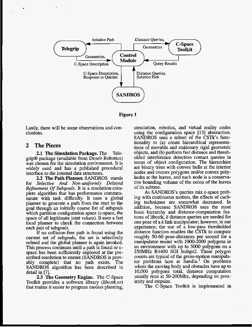
Figure 1
Lastly, there will be some observations and con- clusions.
2 ThePieces 2.1 The Simulation Package. The Tele-
grip@ package (available from Deneb Robotics) was chosen for the simulation environment. It is widely used and has a published procedural interface to the internal data structures.
2.2 The Path Planner. SANDROS stands for Selective And Non-uniformly Delayed ReJnement Of Subgoals. It is a resolution-com- plete algorithm that has performance commen- surate with task difficulty. It uses a global planner to generate a path from the start to the goal through an initially coarse list of subgoals which partition configuration space (c-space, the space of all legitimate joint values). It uses a fast local planner to check the connection between each pair of subgoals.
If no collision-free path is found using the current set of subgoals, the set is selectively refined and the global planner is again invoked. This process continues until a path is found or c- space has been sufficiently explored at the pre- scribed resolution to ensure (SANDROS is prov- ably complete) that no path exists. The SANDROS algorithm has been described in detail in [7].
2.3 The Geometry Engine. The C-Space Toolkit provides a software library (Zibcstk.so) that makes it easier to program motion planning,
simulation, robotics, and virtual reality codes using the configuration space [ 131 abstraction. SANDROS uses a subset of the CSTk’s func- tionality to (a) create hierarchical representa- tions of movable and stationary rigid geometric objects, and (b) perform fast distance and thresh- olded interference detection contact queries in terms of object configuration. The hierarchies are binary trees with convex hulls at the interior nodes and convex polygons andor convex poly- hedra at the leaves, and each node is a conserva- tive bounding volume of the union of the leaves of its subtree.
As SANDROS’s queries mix c-space prob- ing with continuous motion, the effects of cach- ing techniques are somewhat decreased. In addition, because SANDROS uses the most basic hierarchy and distance-computation fea- tures of libcstk, k distance queries are needed for one pose of a k link manipulator; however, in our experience, the use of a low-pass thresholded distance function enables the CSTk to compute roughly 50-60 pose-distances per second for a manipulator model with 1000-2000 polygons in an environment with up to 5000 polygons on a 250MHz R4400 SGI Indigo2. These polygon counts are typical of the gross-motion manipula- tor problems here at Sandia.’ On problems where the moving body and obstacles have up to 10,000 polygons total, distance computation usually runs at 50-200Mhz, depending on prox- imity and stepsize.
The C-Space Toolkit is implemented in
C++. The current version has been developed and tested on SGI Indigo2 workstations running IRM 5.3, but avoids machine-specific instruc- tions. The software uses the freeware QHull package from U. Minnesota [15] in creating con- vex hulls and arbitrarily-aligned bounding boxes.
3 The Architecture Fortunately, the three software packages
that we integrated have relatively well-defined interfaces and are cleanly separable. The amount of data that must be transferred between pack- ages is generally small, and writing a control module was relatively straightforward.
Figure 1 shows the architecture schemati- cally. The simulation environment initiates the planning of a path by invoking the control mod- ule with a description of c-space and the start and goal points in that c-space. The control mod- ule extracts the geometry (point-polygon infor- mation for each object) from Telegrip and passes it to the C-Space Toolkit. The control module then initiates SANDROS.
The only other information SANDROS requires is the minimum distance between the robot and the obstacles at selected c-space points. To get this distance, SANDROS passes the point coordinates to the control module. The control module obtains from Telegrip the world transformations for each link of the robot and then has the C-Space Toolkit compute the dis- tance. When SANDROS is done, it passes back the resulting path or a failure flag to the control module which in turn notifies Telegrip.
In the discussions that follow, references to SANDROS include the control module and SANDROS. Many of the control mechanisms are actually implemented in the control module as traps when SANDROS does a distance query.
4 Usage and Control The system user can invoke the path plan-
1 In comparison, CSTk completes the “Complex Torus” runs (20K polygon moving object, 98K polygon environment) from U. North Caro- lina, Chapel Hi11[14], at about 31Hz for full distance computation and 44Hz for full con- tact detection.
ner in two ways. From Telegrip’s graphical user interface, the user selects a robot for which a path is to be planned, a start tag point (also known as a frame) and an ending tag. These tags or frames are 6 dimensional points (position and orientation) and indicate where the robot is to place the tool frame or endpoint. Inverse kine- matics are done for each point, yielding start and goal points in c-space. For kinematically redun- dant robots or under-constrained problems, the user can arbitrarily pick. It is these points (sets of joint values) that are actually passed to S A N - DROS. (For underconstrained problems, any number of points in the solution space for the inverse kinematics can be passed to SANDROS. Other types of constraints such as minimum cycle time or minimum distance can then be applied to select the best path.) SANDROS returns an ordered set of points in c-space as the computed path. These are converted to an ordered set of tag points and made into a path in the scene that the robot can follow.
SANDROS can also be invoked from the simulation language that Telegrip provides. The simulation program can call the same routine as the graphical user interface. Alternatively, it can select which c-space points to use and have SANDROS invoked with those. In this case, the ordered set of c-space points is returned rather than the tag points.
There are several parameters that may be varied to control the action of SANDROS. The most obvious of these is the coarseness of the underlying search grid in c-space. This can be modified by specifying the step size for each joint in rotational or linear units depending on whether it is a revolute or prismatic joint. SAN- DROS attempts to stay a safe distance away from all obstacles. The distance that is consid- ered “safe” can be set. Also, the distance at which a collision occurs can be changed. It is normally 0.0 but can be set to a small positive value for an extra margin of safety. SANDROS will approach closer to obstacles than the mini- mum safe distance if it has to but will always detect a collision at or below the collision dis- tance.
These and other, less important parameters can be changed in any of three ways. There is a procedural interface that accepts a parameter name and value. This can be called from the sim- ulation program under user control. Alterna- tively, the desired parameter names and values

can be placed in a SAN- DROS options file. If this file exists locally, SANDROS will read it and change the specified parameters when it begins execution. Thirdly, the values can be modified from the graphical user interface in a pop up window.
Even though S A N - DROS is relatively fast, it is still quite possible for it to take unacceptably long when attempting hard problems. SANDROS has two interrupt mechanisms for just such an occasion. There is a time limit after which SANDROS will return with an indication that it ran out of time. The value of this time limit defaults to forever but it can be set in the same manner as the above mentioned parame-
Table 1: Examples
example Cleaning
robot polygons
obstacle polygons 3500
workcell size 6 x 6 ~ 4 f.
c-space resolution joint 1 joint 2 joint 3 joint 4 joint 5 joint 6
1 deg 1 deg 1 deg 1 deg 1 deg 1 deg
Average Plan Time
Longest Plan Time
ters. The invoking piogram can thus be assured that SANDROS will return in less than a known time. The invoking program can then declare the path unsolvable or take steps to simplify the problem.
In addition, the application can provide a callback function which SANDROS will call at a approximately one second intervals. The appli- cation must return a continue or abort flag. If it returns an abort flag, SANDROS returns imme- diately indicating that it was interrupted. This allows the application to provide the user an abort button in a graphical user interface.
As a secondary function, the callback rou- tine is passed a text string that shows how many distance queries have been made. This is of mar- ginal interest since the total number of distance queries that will be needed is unknown. How- ever, this can provide the proverbial blinking (a.k.a. idiot) light that lets the user know that the system is working and not hung up. It can be very difficult to wait in front of a completely unchanging interface.
5 Examples In the following examples, the cleaning and
gantry examples are real world problems with good simulation models of the physical work-
Spot Weld
4765 2870
40x23~12 ft 12x8~10 ft
5.0 in 5.0 in 1.3 in
4.0 deg 4.0 deg 8.0 deg
1 deg 1 deg 1 deg 2 deg 2 deg 2 deg
cells. The spot weld problem is purely a simula- tion problem with no corresponding real hardware. No effort was made to find particu- larly hard or easy paths in these examples. Rather, several real paths were planned that were needed in the course of everyday work. All examples are 6 DOF problems. The results are shown in Table 1. These examples were run on an SGI Indigo 2 with a 250MHz processor. All times are in wall clock seconds.
5.1 A Program Controlled Example. The first example involves a robot with 6
revolute joints in a medium sized workspace (6 feet on a side). The robot is suspended from the ceiling and controls a nozzle that is used for pre- cision cleaning of a manufactured part. The spray is to be applied very precisely to specific features of the part to maximize effective clean- ing and minimize (possibly hazardous) waste.
There are hundreds of tag points (frames) that must be visited to clean the part. The tag points are calculated automatically since it would be infeasible to teach that many points as precisely as is required. In moving from one tag point to the next, the features of the simulation system are used to determine if there is a colli- sion between the robot and the part or other obstacles in the workcell. If a collision is detected, SANDROS is invoked to compute a

Figure 2
collision-free path. In this application, the goal was to achieve
complete automation of the process. Rather than intervene and manually teach safe points or use an ad hoc method, this new planning capability was applied. As can be seen from table 1, the planning times are quite acceptable. In fact, the path planning turned out to be one of the lessor contributors to the overall time to process a part.
For this example, the longest delay caused by the path planning effort is in extracting the geometry and initializing the geometry engine’s data structures. This takes about 30 seconds. This is not a major drawback as it is only done the first time SANDROS is called. After that, it is only necessary to obtain new transformations for the objects. If the same workcell is going to be used over and over, the geometry engine’s data structures can be saved to disk and reloaded rather than recomputed. This happens in a few seconds.
5.2 A Gantry Robot Example. This example demonstrates the use of the planner through a graphical user interface. The environ- ment is somewhat cluttered. The workcell con- tains two gantry robots, two other robots and tables, tubs and assorted detritus (see figure 2). This workcell is used for various tests and dem- onstrations. Without SANDROS, the workcell operator must manually move the robot very carefully from one spot to another. With SAN- DROS, the workcell operator need only select
the positions to which the robot must move. The planner and control system can then get the robot there safely.
5.3 A Spot Welding Example. Spot weld- ing contains a common requirement of having the robot perform a sequence of tasks at particu- lar locations with collision free motion being the only requirement in moving from one task to the other. This is an ideal application for path plan- ning. In this example, the welder must weld a series of points along the flange of a fender. The two pieces of the fender are held by a fixture.
The planning time to get from one weld point to another is normally less than a second. Only when the robot must go up and over the fix- ture clamps does the time get as high as 10 sec- onds. Clearly, these are times are much faster than teaching points.
6 Conclusions We have successfully integrated the SAN-
DROS path planner into a widely used simula- tion and control system. It is easily and quickly invoked by the user for any problem. The solu- tion times, which are normally on the order of seconds, make it feasible to use automated path planning as the default action rather than teach- ing safe points or using ad hoc methods. As pro- cessors become faster and further improvements are made to the path planning system, we foresee the time when systems will, as a matter of
course, invoke a path planner for every move when not explicitly prevented from doing so.
We now have a greatly expanded universe of examples on which to experiment and experi- ment turnaround time is generally very quick. It is much easier now to find out what SANDROS works well on and what it doesn’t. It is easy to try variations and new ideas for the planner. Fur- thermore, we have seen SANDROS being used in real work for the first time.
One of the first improvements will be to incorporate learning into the planner as described by Chen [16]. In environments that do not change or change slowly, significant improvements can be realized by remembering what was learned of c-space in the previous runs. Another important step will be the inclusion of human interaction. More and more paths will become quickly computable, but there will always remain some difficult problems that require significant exploration of c-space at a very fine resolution. For these problems, human insight could speed up the problem by orders of magnitude.
We have been pleased with the benefits of integrating SANDROS into Telegrip. We expect that other groups would see similar benefits from integrating other planners into widely used simu- lation and control packages. A direct benefit to the entire community of such efforts would be the possibility of creating benchmarks that can be easily exchanged. We could all then easily share interesting experiments and meaningfully compare results.
References [ 13 Jean-Claude Latombe. Robot Motion Planing,
Kluwer Academic Publishers, Norwell, Ma, 1991.
[2] Yong K. Hwang and Narendra Ahuja, “Gross Motion Planning - A Survey,” ACM Computing Surveys, 24(3):219-291, September 1992.
[3] Koichi Kondo, “Motion Planning with Six Degrees of Freedom by Multistrategic Bidirec- tional Heuristic Free-space Enumeration”, IEEE Transactions on Robotics and Automa- tion, 7( 3):267-277, June199 1.
[4] Kamal Kant Gupta, “Fast Collision Avoidance for Manipulator A r m s : A Sequential Search Strategy”, IEEE Transactions on Robotics and Automation, 6(5):522-532, July 1990.
[5] Kamal Kant Gupta and Z. Guo, “Motion Plan- ning for Many Degrees of Freedom”, IEEE Transactions on Robotics and Automation, 11:6, December 1995.
[6] Kamal Kant Gupta and Xinyu Zhu, “Practical Global Motion Planning for Many Degrees of Freedom: A Novel Approach within Sequential Framework”, Proc. IEEE International Confer- ence on Robotics and Automation, pp 2038- 2043,1994.
[7] P.C. Chen and Y.K. Hwang. “SANDROS: A Motion Planner with Performance Proportional to Task Difficulty”, Proc. IEEE International Conference on Robotics and Automation, pp
[8] C. Connolly and R. Grupen, “On the Applica- tion of Harmonic Functions to Robotics”, Jour- nal of Robotics Systems, 10(7):931-946, 1993.
[9] Pierre Bessiere, Juan Manuel Ahuactzin, et al., “The ‘Ariadne’s Clew” Algorithm: Global Planning with Local Methods”, Proc. of IEEW RSJ Conference on Intelligent Robots and Sys- tems, 1993.
[lo] Lydia Kavraki and Jean-Claude Latombe, “Randomized Prepocessing of Configuration Space for Path Planning: Articulated Robots”, IROS, 1994.
[ 1 11 Juan-Manuel Ahuactzin and Kamal Gupta, “On Manipulation Planning”, Proceedings of ZEEE Intemtional Symposium on Assembly and Task Planning, pp 67-72,1995.
[12] S. Cameron C. Qin and A. McLean, “Toward Efficient Motion Planning for Manipulators with Complex Geometry”, Proc. of IEEE Znter- national Symposium on Assembly and Task Planning, pp 207-212, 1995.
[ 131 T. Lozano-Perez, “Spatial Planning: A Config- uration Space Approach”, IEEE Trans. on Computers, 32(2): 108-120, 1983.
[14] S. Gottschalk, M.C. Lin, and D. Manocha, “OBB-Tree: A Hierarchical Structure for Rapid Interference Detection”, Proc. ACM SIG- GRAPH ‘96,1996.
[15] C.B. Barber, D.P. Dobkin, and H. Huhdanpaa, “The Quickhull Algorithm for Convex Hulls”, to appear in ACM Trans. on Mathematical SOB- ware. Also as Tech. Rept. GCG 53, Geometry Center at U. Minnesota, 1993.
[16] P.C. Chen, “Adaptive Path Planning: Algorithm and Analysis”, Proc. IEEE International Con- ference on Robotics and Automation, pp 721-
2346-2353,1992.

c
728,1995
DISCLAIMER
This report was prepared as an account of work sponsored by an agency of the United States Government. Neither the United States Government nor any agency thereof, nor any of their employees, makes any warranty, express or implied, or assumes any legal liability or responsi- bility for the accuracy, completeness, or usefulness of any information, apparatus, product, or process disclosed, or represents that its use would not infringe privately owned rights. Refer- ence herein to any specific commercial product, process, or sewice by trade name, trademark, manufacturer, or otherwise does not necessarily constitute or imply its endorsement, recom- mendation, or favoring by the United States Government or any agency thereof. The views and opinions of authors expressed herein do not necessarily state or reflect' those of the United States Government or any agency thereof.