90202-1003dea kf121 installation and connection manual · warning failure to comply with indicated...
TRANSCRIPT

Kawasaki Heavy Industries, Ltd.
90202-1003DEA
Kawasaki Robot KF121
Installation and Connection Manual
(E Controller)
KF121 Kawasaki Robot Installation and Connection Manual
1
PREFACE
This manual explains the installation and connection procedures for Kawasaki Painting Robot
KF121.
Read and understand the contents of this manual and the safety manuals thoroughly, and strictly
observe all safety rules before proceeding with any operation.
This manual describes only the installation and connection of KF121 series robot arm. For
installation and connection of the controller and cables, see the separate manual “Installation and
Connection Manual” for the controller for explosion-proof robot.
Kawasaki will not take any responsibility for any accidents and/or damages caused by operations
that are based on only a limited reading of this manual.
1. This manual does not constitute a guarantee of the systems in which the robot is utilized.
Accordingly, Kawasaki is not responsible for any accidents, damages, and/or problems
relating to industrial property rights as a result of using the system.
2. It is recommended that all personnel assigned for activation of operation, teaching,
maintenance or inspection of the robot attend the necessary education/training course(s)
prepared by Kawasaki, before assuming their responsibilities.
3. Kawasaki reserves the right to change, revise, or update this manual without prior notice.
4. This manual may not, in whole or in part, be reprinted or copied without the prior written
consent of Kawasaki.
5. Store this manual with care and keep it available for use at any time. If the robot is
reinstalled or moved to a different site or sold off to a different user, attach this manual to the
robot without fail. In the event the manual is lost or damaged severely, contact Kawasaki.
Copyright © 2010 Kawasaki Heavy Industries Ltd. All rights reserved.
KF121
This manual is applicable to the following robot model.

KF121 Kawasaki Robot Installation and Connection Manual
2
SYMBOLS
The items that require special attention in this manual are designated with the following symbols.
Ensure proper and safe operation of the robot and prevent physical injury or property damage by
complying with the safety matters given in the boxes with these symbols.
Denotes precautions regarding robot specification,
handling, teaching, operation, and maintenance.
[ NOTE ]
Failure to comply with indicated matters can result
in imminent injury or death.
DANGER !
Failure to comply with indicated matters may
possibly lead to injury or death.
WARNING!
Failure to comply with indicated matters may lead
to physical injury and/or mechanical damage.
CAUTION !
1. The accuracy and effectiveness of the diagrams, procedures, and detail
explanations given in this manual cannot be confirmed with absolute
certainty. Accordingly, it is necessary to give one’s fullest attention
when using this manual to perform any work.
2. Safety related contents described in this manual apply to each individual
work and not to all robot work. In order to perform every work in
safety, read and fully understand the safety manual, all pertinent laws,
regulations and related materials as well as all the safety explanations
described in each chapter, and prepare safety measures suitable for
actual work.
WARNING!

KF121 Kawasaki Robot Installation and Connection Manual
3
Preface ..................................................................................................................................................1
Symbols................................................................................................................................................2
1.0 Precautions .................................................................................................................................4
1.1 Precautions during Transportation and Storage........................................................................4
1.2 Installation Environment of the Robot Arm..............................................................................5
1.3 Cautionary Instructions for Explosion-Proof............................................................................6
1.4 Warning Labels ..........................................................................................................................7
2.0 Motion Range & Specifications of Robot.................................................................................8
3.0 Work Flow at Arm Installation and Connection.....................................................................11
4.0 Robot Transportation Method .................................................................................................12
4.1 Wire Sling.................................................................................................................................12
4.2 Forklift ......................................................................................................................................13
5.0 Installing Dimensions of Base Section....................................................................................14
6.0 Installation Method of Robot Pedestal ....................................................................................15
7.0 Installation Method ..................................................................................................................16
8.0 Mounting of Tools ...................................................................................................................19
8.1 Dimensions of Wrist End (Flange)..........................................................................................19
8.2 Specification of Mounting Bolts..............................................................................................19
8.3 Calculating the Load on Wrist Axis ........................................................................................20
9.0 Connection of Air System .......................................................................................................22
9.1 Explosion-Proof Specifications ...............................................................................................22
9.2 Air Supply to Robot Arm ........................................................................................................22
9.2.1 For Japan Explosion-Proof Specification .............................................................................. 22
9.2.2 For China Explosion-Proof Specification.............................................................................. 23
10.0 Connecting Robot Arm to Controller with Harnesses............................................................24
10.1 Cautionary Instructions for Connecting Harnesses.................................................................24
CONTENTS

KF121 1. Precautions Kawasaki Robot Installation and Connection Manual
4
1.0 PRECAUTIONS
1.1 PRECAUTIONS DURING TRANSPORTATION AND STORAGE
When transporting the Kawasaki Robot to its installation site, strictly observe the following
cautions.
1. When the robot arm is to be transported by using a crane or forklift,
never support the robot arm manually.
2. During transportation, never climb on the robot or stay out from
under the lifted robot arm.
WARNING!
1. Since the robot arm is composed of precision parts, be careful not to
apply excessive shocks or vibrations during transportation.
2. Prior to installation, remove all obstacles so the installation is carried
out smoothly and safely. Clear a passage to the installation area for
transportation of the robot arm using a crane or forklift.
3. During transportation and storage,
(1) keep the ambient temperature within the range of minus 10 - 60C,
(2) keep the relative humidity within the range of 35 - 85% RH
without dew condensation,
(3) keep free from excessively strong vibration.
CAUTION !

KF121 1. Precautions Kawasaki Robot Installation and Connection Manual
5
1.2 INSTALLATION ENVIRONMENT OF THE ROBOT ARM
KF121 robot arm must be installed in a place that satisfies all the following environmental
conditions:
1. When robot is installed on the floor, the levelness must be within 5 . 2. Be sure that the installation floor/pedestal has sufficient rigidity.
3. Secure a flatness to prevent undue force applied to the installation section. (If
sufficient flatness is unobtainable, insert liners and adjust the flatness within 0.3.)
4. Keep the ambient temperature during operation within the range of 0 - 40 °C.
(Deviation or overload error may occur due to high viscosity of grease/oil when starting
operation at low temperatures. In this case, perform warm-up operation at low speed
before regular operation.)
5. Keep the relative humidity during operation within the range of 35-85 %RH without
dew condensation.
6. The robot installing place should be free from dust, dirt, smoke, water, and other foreign
matters.
7. The robot installing place should be free from excessively strong vibration.
8. The robot installing place should be free from electric noise interference.
9. The robot installing place should be sufficiently larger than the motion range of robot
arm. Install safety fence so the maximum movement of fully equipped robot arm (with
tools) does not cause interference.
(1) Provide an entrance door with a safety plug for the safety fence.
(2) Follow national and local standards regarding safety fence construction/function.
(e.g. EN953, EN294, EN811, EN1088, ISO13852, ISO13854, ISO/NP14120)
Approx.1 m Motion range of robot
A door with safety plug
Approx.1 m
Safety fence
Mechanical stopper
Mechanicalstopper
Approx.1 m Approx.1 m
Approx.1 m
Protect sealed joints, etc. on the robot arm axes with vinyl sheets, etc. to
prevent paint mist/foreign materials from entering.
[ NOTE ]

KF121 1. Precautions Kawasaki Robot Installation and Connection Manual
6
Non-hazardous area Hazardous area
Teach pendant Controller
Robot arm
Air supply source (0.3-0.7 MPa)
1.3 CAUTIONARY INSTRUCTIONS FOR EXPLOSION-PROOF
KF121 is an explosion-proof type robot protected by pressurized and intrinsically safe structures.
Strictly observe the following instructions for safe operation.
1. This painting robot has pressurized enclosures for explosion-proof
specifications. Before loosening the bolts from the pressurized
enclosure, always follow instructions from the person in charge.
(1) Do not loosen tightening bolts of pressurized enclosures without
instructions from the person in charge.
(2) Do not open the cover of a pressurized enclosure while electricity is
supplied to robot.
2. Install controller in a non-hazardous area where there is no possibility
of explosion. Before accessing the robot for maintenance, inspection,
or for inspection and adjustments of painting equipment, always turn
OFF the external power for shutting off power supply to the robot
controller, close the air supply valve and confirm there is no residual
pressure in any air supply lines.
DANGER !

KF121 1. Precautions Kawasaki Robot Installation and Connection Manual
7
1.4 WARNING LABELS
Warning label for pinching
Warning label for high temperature
View A
During operations, pay attention to the warning
labels indicated in the figures below.
WARNING!

KF121 2. Motion Range & Specifications of Robot Kawasaki Robot Installation and Connection Manual
8
2.0 MOTION RANGE & SPECIFICATIONS OF ROBOT
DETERMINATION OF SAFETY FENCE INSTALLATION LOCATION
The motion range of robot arm is represented by Point B in the figure above. Accordingly, the
dimensions of safety fence should be determined as follows: Calculate sum of L0, L1 and L2 for
minimum dimension. That is: distance from the center of arm (Point A shown in the figure
above) to Point B (=L0) + distance from the center of wrist to the edge of tool/workpiece (=L1) +
allowance (=L2). For the value of L0, see Motion Range & Specifications of Robot on the
following pages.
L2
Safety Fence
L1
L0
Position of Mechanical Stopper
Position of Mechanical Stopper
Point B
Tool
Point B
Motion range of Point B
Workpiece

KF121 2. Motion Range & Specifications of Robot Kawasaki Robot Installation and Connection Manual
9
KF121
Floor mounted spec.
Type Articulated robot
Degree of
freedom 6
JT Motion range Max. speed
1 320 220 /s
2 180 120 /s
3 480 240 /s
4 540 430 /s
5 290 430 /s
Motion range &
speed
6 720 720 /s
Load capacity 5 kg
JT Torque Moment of inertia
4 7.8 Nm 0.17 kgm2
5 7.8 Nm 0.17 kgm2
Wrist load
capacity
6 2.9 Nm 0.06 kgm2
Repeatability ±0.2 mm
Mass Approx. 140 kg
Acoustic noise 74 dB (A)*
NOTE* measured condition:
・1000 mm away from the end
of robot motion range
(Noise level changes
depending on conditions.)

KF121 2. Motion Range & Specifications of Robot Kawasaki Robot Installation and Connection Manual
10
KF121
Wall mounted spec.
Type Articulated robot
Degree of
freedom 6
JT Motion range Max. speed
1 120 120 /s
2 180 120 /s
3 480 240 /s
4 540 430 /s
5 290 430 /s
Motion range &
speed
6 720 720 /s
Load capacity 5 kg
JT Torque Moment of inertia
4 7.8 Nm 0.17 kgm2
5 7.8 Nm 0.17 kgm2
Wrist load
capacity
6 2.9 Nm 0.06 kgm2
Repeatability ±0.2 mm
Mass Approx. 140 kg
Acoustic noise 74 dB (A)*
NOTE* measured condition:
・1000 mm away from the end
of robot motion range
(Noise level changes
depending on conditions.)

KF121 3. Work Flow at Arm Installation and Connection Kawasaki Robot Installation and Connection Manual
11
3.0 WORK FLOW AT ARM INSTALLATION AND CONNECTION
This flowchart describes only the robot arm section. For the controller, refer to separate
Installation and Connection Manual for Explosion-proof robot controller.
Examination of Installation Place and Motion Range
Refer to 2. Motion Range & Specifications of Robot.
Examination & Preparation of Transportation Method and Installation Plane Surface
Refer to 4. Robot Transportation Method, 5. Installing Dimensions of Base Section, 6. Installation Method of Robot Pedestal, 7. Installation Method.
Transportation of Robot Arm Refer to 4. Robot Transportation Method.
Mounting of Tools Refer to 8. Mounting of Tools and 9. Connection of Air System.
Completion of Work
Connection to Controller
Refer to Installation and Connection Manual for explosion-proof robot controller and 10. Connecting Robot Arm to Controller with Harnesses.
Pre
para
tion
Refer to 5. Installing Dimensions of Base Section, 6. Installation Method of Robot Pedestal, 7. Installation Method.
Installation of Robot Arm
Act
ual W
ork
Check of Arm Motion Check of Tool Motion Refer to Operation Manual.
Check of Other Functions
Wor
k U
sing
Con
trol
ler
Refer to Operation Manual.

KF121 4. Robot Transportation Method Kawasaki Robot Installation and Connection Manual
12
4.0 ROBOT TRANSPORTATION METHOD
4.1 WIRE SLING
Hoist up the robot by fastening wires to two eyebolts (M10), holding the upper arm (arm 2) as
shown in the figure below. (Hoist up the robot with the pedestal/ base plate in the same way.)
Model KF121
Hoisted posture*
JT1 0 0 JT2 -4 -25 JT3 130 -150 JT4 0 0 JT5 46 -55
Hoisting
posture
JT6 0 0 NOTE* Consult Kawasaki on the hoisting postures for the wall mounted robot arm.
When hoisting up robot, be careful because robot may lean forward/
backward/left/right depending on the robot posture. Be sure to hoist up the
robot in the specified hoisting postures below, otherwise it may swing
excessively or the wire may interfere with other objects, resulting in damage.
In places where wire touches the arm, protect arm with board, etc.
WARNING!

KF121 4. Robot Transportation Method Kawasaki Robot Installation and Connection Manual
13
4.2 FORKLIFT
There is no jig for the forklift. Transport the robot arm using wires by a forklift in the same way
as you transport the robot by wire sling. Be careful when transporting the robot by a forklift
because the robot may fall when the wire slips due to oscillation, etc.

KF121 5. Installing Dimensions of Base Section Kawasaki Robot Installation and Connection Manual
14
5.0 INSTALLING DIMENSIONS OF BASE SECTION
When installing the base section, fix it with high-tension bolts through the bolt holes on the base
section using the plane washer.
Model KF121
Installing
dimensions of
base section
Cross-section
of installation
bolt hole
Bolt holes 7-14
High tension
bolts
7-M12
Material: SCM435
Strength: 10.9 or more
Tightening
torque 98 Nm
Levelness Within ±5
(Equally divided into 8)
Be sure to install the arm on a surface with flatness
of 0.3 mm or less, otherwise robot arm may suffer
damage.
CAUTION !
KF121 6. Installation Method of Robot Pedestal Kawasaki Robot Installation and Connection Manual
15
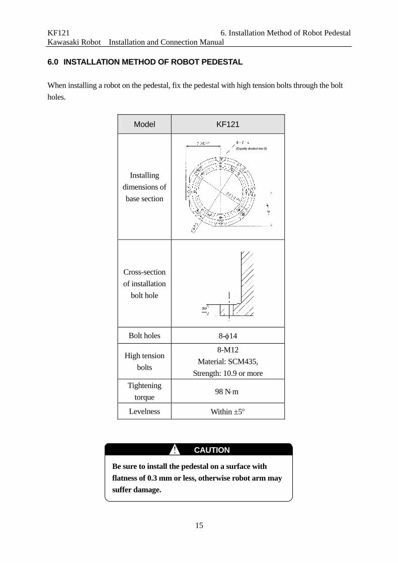
6.0 INSTALLATION METHOD OF ROBOT PEDESTAL
When installing a robot on the pedestal, fix the pedestal with high tension bolts through the bolt
holes.
Model KF121
Installing
dimensions of
base section
Cross-section
of installation
bolt hole
Bolt holes 8-14
High tension
bolts
8-M12
Material: SCM435,
Strength: 10.9 or more
Tightening
torque 98 Nm
Levelness Within ±5
(Equally divided into 8)
Be sure to install the pedestal on a surface with
flatness of 0.3 mm or less, otherwise robot arm may
suffer damage.
CAUTION !

KF121 7. Installation Method Kawasaki Robot Installation and Connection Manual
16
7.0 INSTALLATION METHOD
1. When installing the base section of the robot arm directly on the floor*
Embed a steel plate (20 mm min. thick) in the concrete floor and fix the base section on it as
shown in the figure below or fix the base section directly on the concrete floor with anchors.
Fix the steel plate firmly enough to endure the reaction forces produced by the robot.
Model KF121
M
(Inversion moment) 2617 Nm
T
(Rotating torque) 1706 Nm
NOTE* Consult Kawasaki on the installation method for the wall mounted robot arm.
Concrete
Steel plate
18mmmin.
20 mm min.
Tightening torque: 98 Nm (1000 kgfcm)

KF121 7. Installation Method Kawasaki Robot Installation and Connection Manual
17
2. When installing the robot pedestal on the floor*
In this case, the installation procedure is practically the same as that in installing the base
section of the robot arm directly on the floor.
Model KF121
Pedestal installation bolt 8-M12
Tightening torque 98 Nm
L1 18 mm or more
L2 20 mm or more
The reaction force received from the robot is the same as that in installing the base section of the
arm directly on the floor.
NOTE* Consult Kawasaki on the installation method for the wall mounted robot arm.
Concrete
Steel plate
18 mm min.
20 mm min.
Tightening torque: 98 Nm (1000 kgfcm)

KF121 7. Installation Method Kawasaki Robot Installation and Connection Manual
18
3. When installing the base section of the robot arm with the robot base plate*
Fix the base plate on concrete floor or steel floor using four of 20 or 22 bolt holes (PCD800)
on the base plate and install the arm. The reaction force received from the robot is the same
as that in installing the base section of the robot arm directly on the floor.
Model KF121
D 20 mm
L 20 mm
NOTE* Consult Kawasaki on the installation method for the wall mounted robot arm.
Concrete
Steel plate

KF121 8. Mounting of Tools Kawasaki Robot Installation and Connection Manual
19
8.0 MOUNTING OF TOOLS
8.1 DIMENSIONS OF WRIST END (FLANGE)
8.2 SPECIFICATION OF MOUNTING BOLTS
Select mounting bolts with proper length depending on the tap depth of tool mounting flange to
secure the specified engagement length. Use high tension mounting bolts and tighten them to
the torque specified in the table below.
Model KF121
Tap hole 4-M6
P.C.D 40
Pin 2-6H7 Depth 6
Spigot hole 25H7 Depth 2.5
Tap depth 12 mm
Length of
engagement 6-12 mm
High tension bolt SCM435, 10.9 min
Tightening torque 11.76 Nm
In the robot arm end section, a flange is
provided on which tools are mounted.
Screw the mounting bolts into the tap
holes on the circumference of 102 on the
flange, referring to the left figure.
Moreover, position the tool by utilizing
the pin hole and the spigot hole.
Mounting bolt
Hand part
Check tightening torque.
Tap depth Check length of engagement.
Tool mounting flange
Tap hole
Spi
got h
ole
4-M6 Penetrate
Pin hole
Prior to mounting tools on the robot, turn OFF the controller power switch
and the external power switch. Display signs indicating clearly “Installation
and connection in progress”, and lockout/tagout the external power switch.
WARNING!
If the engagement length has exceeded the specified value, the mounting bolt
interferes with fixed section, and the flange will not move.
CAUTION !

KF121 8. Mounting of Tools Kawasaki Robot Installation and Connection Manual
20
8.3 CALCULATING THE LOAD ON WRIST AXIS
1. The maximum load capacity of the robot is specified per robot model.
2. Strictly observe the limiting conditions for load mass and load torque and load moment of
inertia around each wrist axis (JT4, JT5, JT6) as shown below.
The load torque and the moment of inertia can be calculated by the following formula.
Load mass (including tool) : M≦Mmax.(kg)
Load torque : T=9.8ML(Nm)
Load moment of inertia : I=ML2(kgm2)
M,W : Load mass (Example)
KF121 … Mmax. : 5 kg
(Wmax. : 5 kgf)
L : Length from center of rotation axis to load
center of gravity. (Unit: m) (See the left
figure.)
If calculation of load is made by dividing the load into several parts, such as tool and load,
use the total calculation values of each part as load torque and moment of inertia.
Calculating formula
L 6 : Length from JT6 axis
rotation center to load
center of gravity.
L 4 , 5 : Moment of inertia
around center of gravity.
Exceeding the specified load capacity may cause deterioration in
motion performance and shorten the life of robot. The specified load
capacity includes the mass of all attachments such as spray gun, gun
bracket, piping/wiring, etc. If total mass exceeds the capacity
specification, consult Kawasaki before starting operations.
WARNING!

KF121 8. Mounting of Tools Kawasaki Robot Installation and Connection Manual
21
Adhere to the following limiting conditions for the load torque and the load moment of inertia
around each wrist axis.
KF121
Acceptable range for JT4,5
Acceptable range for JT6
kgm2
7.8 8 Nm2.9 2
0.4
0.3
0.2 0.17
0.1
Load torque
Load
mom
ent o
f ine
rtia
0.0
0.39
0.12

KF121 9. Connection of Air System Kawasaki Robot Installation and Connection Manual
22
9.0 CONNECTION OF AIR SYSTEM
9.1 EXPLOSION-PROOF SPECIFICATIONS
KF121 is an explosion-proof specified robot protected by pressurized and intrinsically safe
structures that comply with national laws and safety standards.
9.2 AIR SUPPLY TO ROBOT ARM
9.2.1 FOR JAPAN EXPLOSION-PROOF SPECIFICATION
Air connecting port is provided in base section of robot arm as shown in the figure below.
Supply the air from the port A (tube
diameter 12) in the rear of the robot
arm as show in the figure above.
When purging completes, the air operated valve set on exhaust side closes.
After that, air consumption is minimized to only a little air leakage from
various sealed sections.
Port A Tube diameter ø 12
Robot arm side regulator (in operation)Pressure setting: 0.01 MPa
Robot arm side regulator (in purging) Pressure setting: 0.12 MPa Pilot air for external axis
Tube diameter 8
Do not change regulator setting on side of
robot arm as it is adjusted at factory
shipment.
CAUTION !
Use clean air that meets specifications below.
1. Solid material ... 0.01 m or less
2. Oil content......... Mist separation: 99.9999 % or more
3. Humidity ........... Dew point: -17 C or less at atmospheric pressure.
4. Input pressure .. 0.3 - 0.7 MPa (4.1 - 7.1 kgf/cm2)
5. Input quantity .. 300 L/min. (nor) (Only at purging)
! CAUTION
KF121 9. Connection of Air System Kawasaki Robot Installation and Connection Manual
23
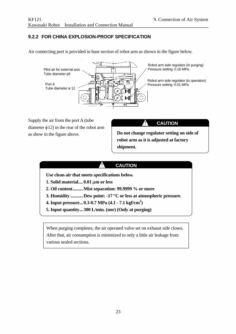
9.2.2 FOR CHINA EXPLOSION-PROOF SPECIFICATION
Air connecting port is provided in base section of robot arm as shown in the figure below.
Supply the air from the port A (tube
diameter 12) in the rear of the robot arm
as show in the figure above.
Port A Tube diameter ø 12
Robot arm side regulator (in operation)Pressure setting: 0.01 MPa
Robot arm side regulator (in purging) Pressure setting: 0.16 MPa Pilot air for external axis
Tube diameter 8
When purging completes, the air operated valve set on exhaust side closes.
After that, air consumption is minimized to only a little air leakage from
various sealed sections.
Do not change regulator setting on side of
robot arm as it is adjusted at factory
shipment.
CAUTION !
Use clean air that meets specifications below.
1. Solid material.... 0.01 m or less
2. Oil content......... Mist separation: 99.9999 % or more
3. Humidity ........... Dew point: -17 C or less at atmospheric pressure.
4. Input pressure... 0.3-0.7 MPa (4.1 - 7.1 kgf/cm2)
5. Input quantity... 300 L/min. (nor) (Only at purging)
! CAUTION

KF121 10. Connecting Robot arm to Controller with Harnesses Kawasaki Robot Installation and Connection Manual
24
10.0 CONNECTING ROBOT ARM TO CONTROLLER WITH HARNESSES
10.1 CAUTIONARY INSTRUCTIONS FOR CONNECTING HARNESSES
Strictly observe the following instructions when connecting separate harnesses.
For Japan and China explosion-proof specifications
1. Follow the national and local standards for installing harnesses.
2. Be sure to use the correct harness cable and check that connector fittings match
between the harness side and controller side before attempting connection.
Using an incorrect harness, or forcing or misconnecting the harness may damage
connectors or cause a break in the electrical system.
3. Use conduits, ducts, etc. to prevent people or equipment (forklift, etc.) from
stepping on or riding over the signal and motor harness lines. An unprotected
harness may become damaged causing breaks in the electrical system.
4. Do not bundle or run the robot motor and signal harnesses together. Signal
harness is specified for use in intrinsically safe circuit and must be separated or
wired independently from other harness lines using a duct. Also, keep away
signal harness line a minimum of 1 m from any high voltage/current lines.
Noise generated from high voltage/current lines will cause malfunctions.
5. Make the separate harnesses as short as possible.
CAUTION !
Hazardous area
Teach pendant
Controller
Robot arm
Seal fitting
Signal harness
Motor harness
Air supply source (0.3-0.7MPa)
V3B harness
V1B harness
Non-hazardous area

Kawasaki Robot KF121 Installation and Connection Manual
October 2010 : 1st Edition
Publication: KAWASAKI HEAVY INDUSTRIES, LTD.
90202-1003DEA
Copyright 2010 KAWASAKI HEAVY INDUSTRIES, LTD. All rights reserved.