9013 pumptrol pressure switches type f and 9013 …
TRANSCRIPT

Catalog
January
07
9013 PUMPTROL® Commercial Pressure Switches Type F and 9013 Commercial Pressure Switches Type G


3
Contents Commercial Pressure Switches
Electromechanical Square D Brand 9013 Pressure Switchesb Selection. . . . . . . . . . . . . . . . . . . . . . . . . . . . . . . . . . . . . . . . . . . . . . pages 4 to 5
b Presentation . . . . . . . . . . . . . . . . . . . . . . . . . . . . . . . . . . . . . . . . . . . pages 6 to 7
b Characteristics. . . . . . . . . . . . . . . . . . . . . . . . . . . . . . . . . . . . . . . . . pages 8 to 9
b 9013FSG PUMPTROL® Commercial Pressure Switches
v Reference Numbers. . . . . . . . . . . . . . . . . . . . . . . . . . . . . . . . . . pages 10 to 11
v Pressure Codes . . . . . . . . . . . . . . . . . . . . . . . . . . . . . . . . . . . . . . . . . . . . . . . 10
v Ordering Information . . . . . . . . . . . . . . . . . . . . . . . . . . . . . . . . . . . . . . . . . . . 10
v Modifications . . . . . . . . . . . . . . . . . . . . . . . . . . . . . . . . . . . . . . . . . . . . . . . . . 11
b 9013FTG PUMPTROL® Commercial Pressure Switches
v Reference Numbers. . . . . . . . . . . . . . . . . . . . . . . . . . . . . . . . . . pages 12 to 13
v Pressure Codes . . . . . . . . . . . . . . . . . . . . . . . . . . . . . . . . . . . . . . . . . . . . . . . 12
v Ordering Information . . . . . . . . . . . . . . . . . . . . . . . . . . . . . . . . . . . . . . . . . . . 12
v Modifications . . . . . . . . . . . . . . . . . . . . . . . . . . . . . . . . . . . . . . . . . . . . . . . . . 13
b 9013FYG PUMPTROL® Commercial Pressure Switches
v Reference Numbers. . . . . . . . . . . . . . . . . . . . . . . . . . . . . . . . . . pages 14 to 15
v Pressure Codes . . . . . . . . . . . . . . . . . . . . . . . . . . . . . . . . . . . . . . . . . . . . . . . 14
v Ordering Information . . . . . . . . . . . . . . . . . . . . . . . . . . . . . . . . . . . . . . . . . . . 14
v Modifications . . . . . . . . . . . . . . . . . . . . . . . . . . . . . . . . . . . . . . . . . . . . . . . . . 15
b 9013FRG PUMPTROL® Commercial Pressure Switches
v Reference Numbers. . . . . . . . . . . . . . . . . . . . . . . . . . . . . . . . . . pages 16 to 19
v Pressure Codes . . . . . . . . . . . . . . . . . . . . . . . . . . . . . . . . . . . . . . . . . . . 16 & 18
v Ordering Information . . . . . . . . . . . . . . . . . . . . . . . . . . . . . . . . . . . . . . . 16 & 18
v Modifications . . . . . . . . . . . . . . . . . . . . . . . . . . . . . . . . . . . . . . . . . . . . . 17 & 19
b 9013FHG PUMPTROL® Commercial Pressure Switches
v Reference Numbers. . . . . . . . . . . . . . . . . . . . . . . . . . . . . . . . . . pages 20 to 21
v Pressure Codes . . . . . . . . . . . . . . . . . . . . . . . . . . . . . . . . . . . . . . . . . . . . . . . 20
v Ordering Information . . . . . . . . . . . . . . . . . . . . . . . . . . . . . . . . . . . . . . . . . . . 20
v Modifications . . . . . . . . . . . . . . . . . . . . . . . . . . . . . . . . . . . . . . . . . . . . . . . . . 21
b 9013G Commercial Pressure Switches
v Reference Numbers. . . . . . . . . . . . . . . . . . . . . . . . . . . . . . . . . . pages 22 to 27
v Pressure Codes . . . . . . . . . . . . . . . . . . . . . . . . . . . . . . . . . . . . . . . . . 22, 24, 26
v Ordering Information . . . . . . . . . . . . . . . . . . . . . . . . . . . . . . . . . . . . . 22, 24, 26
v Modifications . . . . . . . . . . . . . . . . . . . . . . . . . . . . . . . . . . . . . . . . . . . . . . 23, 25
v Replacement Parts . . . . . . . . . . . . . . . . . . . . . . . . . . . . . . . . . . . . . . . . . . . . 27
b 9013 Type F and G
v Dimensions . . . . . . . . . . . . . . . . . . . . . . . . . . . . . . . . . . . . . . . . pages 28 to 29
b Product Reference
v Index . . . . . . . . . . . . . . . . . . . . . . . . . . . . . . . . . . . . . . . . . . . . . . . . . . pages 30

4
Selection guide 0 Commercial Pressure SwitchesElectromechanical Square D Brand 9013Conforming to UL508 and CSA
Applications Type of Installation Power Circuit Power Circuit Power Circuit
Controls Fresh or sea water Fresh or sea water Fresh or sea water
Type of Operation Regulation between 2 thresholds (adjustable differential). Suitable for all pumps.
Detection of a single threshold (non-adjustable differential)
Regulation between 2 thresholds (adjustable differential). For higher HP and pressure requirements.
Family PUMPTROL 9013FSG PUMPTROL 9013FTG PUMPTROL 9013FYG
Size / Range PSI 20 - 65 20 - 65 25 - 80
BAR 1.38 - 4.48 1.38 - 4.48 1.72 - 5.52
Conforming to standards NEMA A600 UL508 UL508 NEMA A600 UL508
Product certifications UL File: E12158 CCN NKPZCSA File: LR 25490
Class 3211 06
UL Listed, CSA Certified UL File: E12158 CCN NKPZCSA File: LR 25490
Class 3211 06
Dimensions (l x h x w) in inches (mm) 3.76 x 2.8 x 2.78(95.5 x 71.12 x 70.6)
3.76 x 2.8 x 2.78(95.5 x 71.12 x 70.6)
3.76 x 2.8 x 2.78(95.5 x 71.12 x 70.6)
Contactblocks
Snap action contacts 2 N.C. 2 N.C. 2 N.C.
Degree of protection NEMA Type 1, NEMA Type 3R, and IP20
NEMA Type 1, NEMA Type 3R, and IP20
NEMA Type 1, NEMA Type 3R, and IP20
Connections Electrical Screw terminals Screw terminals Screw terminalsFluid Multiple Multiple Multiple
Cable Entries 2 2 2
Type reference 9013FSGppp 9013FTGppp 9013FYGppp
Characteristics Page 8 Page 8 Page 8
Interpretation of Reference Numbers Page 10 and 11 Page 12 and 13 Page 14 and 15
Other versions: Form B7, one grommet, CE — — —Form B8, two grommets, CE — — —
.

5
00
Power Circuit Power Circuit Power Circuit
Fresh or sea water Air only Water or Air
Reverse acting, contacts open on falling pressure (adjustable differential)
Controls electrically driven air compressors, contacts open on rising pressure (non-adjustable differential, adjustable cut-out), diaphragm actuated
Light industrial, with higher electrical ratings for direct control of motors in pumps and compressors, contacts open on rising pressure (adjustable differential)
PUMPTROL 9013FRG PUMPTROL 9013FHG 9013G
6 - 150 40 - 200 10 - 250
0.41 - 10.34 2.76 - 13.79 0.69 - 17.24
NEMA A300 UL508 NEMA A600 UL508 NEMA A600 UL508
UL File: E12158 CCN NKPZCSA File: LR 25490
Class 3211 06
UL Listed, CSA Certified UL File: E12158 CCN NKPZ (except GHR and GSR)UL File: E12443 CCN NOWT (for GHR and GSR)CSA File: LR 25490 Class 3211 06 (execpt GHR and GSR)CSA File: LR 26817 Class 3218 05 (for GHR and GSR)
3.76 x 2.8 x 2.78(95.5 x 71.12 x 70.6)
3.76 x 2.8 x 2.78(95.5 x 71.12 x 70.6)
3.68 x 3.85 x 3.44(93.47 x 97.79 x 87.37)
2 N.C. 2 N.C. 2 N.C.
NEMA Type 1, NEMA Type 3R, and IP20
NEMA Type 1, NEMA Type 3R, and IP20
NEMA Type 1, NEMA Type 3R, NEMA Type 7, NEMA Type 9, and IP20
Screw terminals Screw terminals Screw terminalsMultiple Multiple Multiple2 2 3 knock-outs available
9013FRGppp 9013FHGppp 9013Gppp
Page 9 Page 9 Page 9
Page 16 - 19 Page 20 and 21 Page 22 - 27
— — —— — —

6
Presentation Commercial Pressure SwitchesElectromechanical Square D Brand 9013For power circuits, FSG, FTG, FYG, FRG, FHG, and G
The PUMPTROL® 9013 Type F Commercial Pressure Switches are UL Listed and CSA Certified as commercial control equipment. Type G pressure switches are UL Listed and CSA Certified as commercial / light industrial control equipment.
The Type FHG - PUMPTROL® Compressor Pressure Switch is used to control electrically driven air compressors and is diaphragm actuated and has contacts that open on rising pressure.
The Type FSG, FYG, FRG - PUMPTROL® Water Pump Pressure Switches are used to control electrically driven water pumps and have the following features:The Type FSG is the standard water pump switch, suitable for all types of pumps: jets, submersible, reciprocating, etc.
The Type FYG is designed to meet higher horsepower and pressure requirements.The Type FRG is reverse acting: the contacts open on falling pressure.All are diaphragm actuated.
The Type G Commercial/Light Industrial Pressure Switch is used to control electrically driven water pumps and air compressors. It has higher electrical ratings for direct control of motors in pump and compressor applications. The Type G switch is diaphragm actuated and has contacts that open on rising pressure.
Every pressure switch has two operating points; one on rising pressure and one of falling pressure. The operating point on rising pressure is referred to as the TRIP POINT or cut out for pumps and compressors and the operating point on falling pressure is referred to as the RESET POINT or cut in for pumps and compressors. These operating points are called the SETTINGS of the switch.
The differential is the difference in pressure between the trip point (cut-out) and the reset point (cut-in). It can be adjustable or non-adjustable. Example: Cut-in (30 psi) / Cut-out (50 psi) Differential equals 20 psi
The range indicates the pressure limits within which the operating points (settings) can be adjusted. The range is referenced to the operating point on rising pressure (trip point). The differential subtracts from the trip point setting.
During the normal operating cycle, system pressure should never exceed the upper limit of the range when using a diaphragm actuated switch. This will greatly reduce the life of the diaphragm.
Maximum allowable pressure is the pressure to which a switch can be subjected without causing a change in operating characteristics, shift in settings, or damage to the device.
Pressure surges may occur in a system during the start up of a machine or from valve operation. Surges are not normally detrimental to the life of a switch if the surge is within the maximum allowable pressure rating of the switch. Diaphragm actuated switches should not be subjected to more than 10 surges per day. More frequent surges will greatly reduce the life of the diaphragm.
Presentation
Operating Points
Differential
Range
Maximum Allowable Pressure

7
Commercial Pressure SwitchesElectromechanical Square D Brand 9013For power circuits, FSG, FTG, FYG, FRG, FHG, and G
When setting the pressure switch, adjust the switching point on rising pressure first and then the switching point on falling pressure.
Switching point on falling pressure The switching point on falling pressure is set by adjusting screw-nut 1.
Switching point on rising pressureThe switching point on rising pressure is set by adjusting screw-nut 2.
Only the switching point on rising pressure is adjustable.
Switching point on rising pressureThe switching point on rising pressure is set by adjusting screw-nut 1.
Switching point on falling pressureThe switching point on falling pressure is not adjustable. The difference between the tripping and resetting points of the contact is the differential of the switch (contact differential, friction, etc.).
When setting the pressure switch, adjust the switching point on rising pressure first and then the switching point on falling pressure.
Switching point on falling pressure The switching point on falling pressure is set by adjusting screw-nut 1.
Switching point on rising pressureThe switching point on rising pressure is set by adjusting screw-nut 2.
SettingsPressure switches with adjustable differential (Types FSG, FYG and FRG)
1
2
Pressure switches with non-adjustable differential (Types FTG, and FHG)1
Pressure switches with adjustable differential (Type G)
1
2
8
Characteristics Commercial Pressure Switches 0
Electromechanical Square D Brand 9013For power circuits, FSG, FTG, FYG
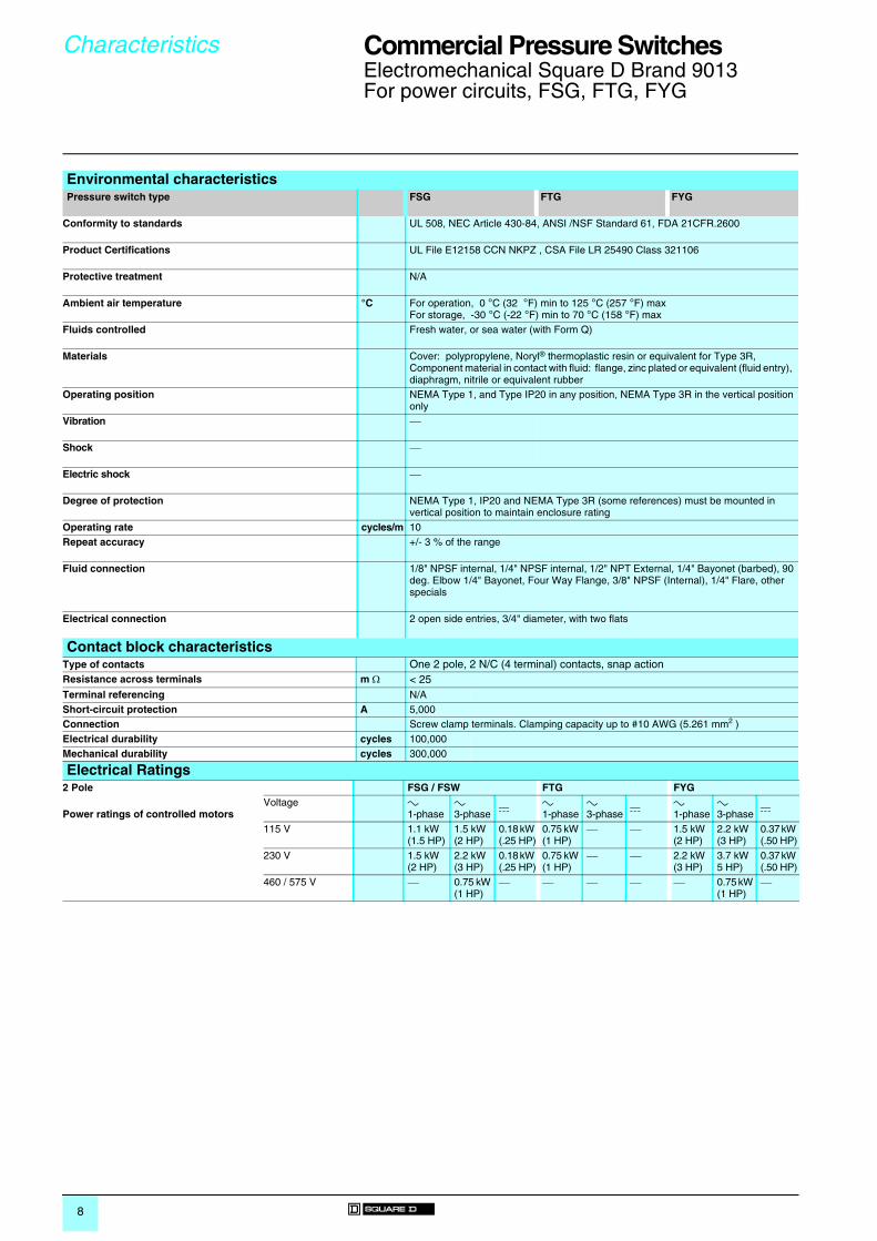
Environmental characteristicsPressure switch type FSG FTG FYG
Conformity to standards UL 508, NEC Article 430-84, ANSI /NSF Standard 61, FDA 21CFR.2600
Product Certifications UL File E12158 CCN NKPZ , CSA File LR 25490 Class 321106
Protective treatment N/A
Ambient air temperature °C For operation, 0 °C (32 °F) min to 125 °C (257 °F) maxFor storage, -30 °C (-22 °F) min to 70 °C (158 °F) max
Fluids controlled Fresh water, or sea water (with Form Q)
Materials Cover: polypropylene, Noryl® thermoplastic resin or equivalent for Type 3R, Component material in contact with fluid: flange, zinc plated or equivalent (fluid entry), diaphragm, nitrile or equivalent rubber
Operating position NEMA Type 1, and Type IP20 in any position, NEMA Type 3R in the vertical position only
Vibration ⎯
Shock ⎯
Electric shock ⎯
Degree of protection NEMA Type 1, IP20 and NEMA Type 3R (some references) must be mounted in vertical position to maintain enclosure rating
Operating rate cycles/m 10Repeat accuracy +/- 3 % of the range
Fluid connection 1/8" NPSF internal, 1/4" NPSF internal, 1/2" NPT External, 1/4" Bayonet (barbed), 90 deg. Elbow 1/4" Bayonet, Four Way Flange, 3/8" NPSF (Internal), 1/4" Flare, other specials
Electrical connection 2 open side entries, 3/4" diameter, with two flats
Contact block characteristicsType of contacts One 2 pole, 2 N/C (4 terminal) contacts, snap action Resistance across terminals m Ω < 25Terminal referencing N/AShort-circuit protection A 5,000Connection Screw clamp terminals. Clamping capacity up to #10 AWG (5.261 mm2 )Electrical durability cycles 100,000Mechanical durability cycles 300,000
Electrical Ratings2 Pole FSG / FSW FTG FYG
Power ratings of controlled motorsVoltage a
1-phasea 3-phase
c a 1-phase
a 3-phase
c a 1-phase
a 3-phase
c
115 V 1.1 kW (1.5 HP)
1.5 kW (2 HP)
0.18 kW (.25 HP)
0.75 kW (1 HP)
⎯ ⎯ 1.5 kW (2 HP)
2.2 kW (3 HP)
0.37 kW (.50 HP)
230 V 1.5 kW (2 HP)
2.2 kW (3 HP)
0.18 kW (.25 HP)
0.75 kW (1 HP)
⎯ ⎯ 2.2 kW (3 HP)
3.7 kW 5 HP)
0.37 kW (.50 HP)
460 / 575 V ⎯ 0.75 kW (1 HP)
⎯ ⎯ ⎯ ⎯ ⎯ 0.75 kW (1 HP)
⎯

9
Commercial Pressure Switches 0
Electromechanical Square D Brand 9013For power circuits, FRG, FHG, and G
Environmental characteristicsPressure switch type FRG FHG G
Conformity to standards UL 508, NEC Article 430-84, ANSI /NSF Standard 61, FDA 21CFR.2600
Product Certifications UL File E12158 CCN NKPZ , CSA File LR 25490 Class 321106
Protective treatment N/A
Ambient air temperature °C For operation, 0 °C (32 °F) min to 125 °C (257 °F) maxFor storage, -30 °C (-22 °F) min to 70 °C (158 °F) max
Fluids controlled Fresh water, or sea water (with Form Q)
Materials Cover: polypropylene, Noryl® thermoplastic resin or equivalent for Type 3R, Component material in contact with fluid: flange, zinc plated or equivalent (fluid entry), nitrile or equivalent rubber (diaphragm)
Operating position NEMA Type 1, and Type IP20 in any position, NEMA Type 3R in the vertical position only
Vibration resistance ⎯
Shock resistance ⎯
Electric shock protection ⎯
Degree of protection NEMA Type 1, IP20 and NEMA Type 3R (some references) must be mounted in vertical position to maintain enclosure rating
Operating rate cycles/m 10Repeat accuracy +/- 3 % of the range
Fluid connection 1/8" NPSF internal, 1/4" NPSF internal, 1/2"NPT External, 1/4" Bayonet (barbed), 90 deg. Elbow 1/4" Bayonet, Four Way Flange, 3/8" NPSF (Internal), 1/4" Flare, other specials
Electrical connection 2 open side entries, 3/4" diameter, with two flats 3 Conduit1/2" Knockouts
Contact block characteristicsType of contacts One 2 pole, 2 N/C (4 terminal) contacts, snap action Resistance across terminals m Ω < 25Terminal referencing N/AShort-circuit protection A 5,000Connection Screw clamp terminals. Clamping capacity up to #10 AWG (5.261 mm2 )Electrical durability cycles 100,000Mechanical durability cycles 300,000
Electrical Ratings1 Pole FRG FHG q c G
Power ratings of controlled motors
Note: Type FRG and G are all Form H
q Includes FHG 2, 3, 4, 9, 12, 13, 14, 19, 42, 44, 49
Voltage a 1-phase
a 3-phase
c a 1-phase
a 3-phase
c a 1-phase
a 3-phase
c
32 V ⎯ ⎯ ⎯ ⎯ ⎯ ⎯ ⎯ ⎯ ⎯
115 V 0.75 kW (1 HP)
⎯ 0.18 kW (.25 HP)
1.1 kW (1.5 HP)
1.5 kW (2 HP)
0.18 kW (.25 HP)
0.75 kW (1 HP)
⎯ 0.37 kW (.50 HP)
230 V 0.75 kW (1 HP)
⎯ 0.18 kW (.25 HP)
1.5 kW (2 HP)
2.2 kW (3 HP)
0.18 kW (.25 HP)
1.5 kW (2 HP)
⎯ 0.37 kW (.50 HP)
460 / 575 V ⎯ ⎯ ⎯ ⎯ 0.75 kW (1 HP)
⎯ 1.5 kW (2 HP)
⎯ ⎯
2 Pole Voltage a 1-phase
a 3-phase
c a 1-phase
a 3-phase
c a 1-phase
a 3-phase
c
Power ratings of controlled motors
c IncludesFHG 22, 24, 29, 32, 33, 34, 39, 52, 54, 59
32 V ⎯ ⎯ 0.18 kW (.25 HP)
⎯ ⎯ ⎯ ⎯ ⎯ ⎯
115 V 0.75 kW (1 HP)
0.75 kW (1 HP)
0.18 kW (.25 HP)
1.5 kW (2 HP)
2.2 kW (3 HP)
0.37 kW (.50 HP)
1.5 kW (2 HP)
2.2 kW (3 HP)
0.75 kW (1 HP)
230 V 0.75 kW (1 HP)
0.75 kW (1 HP)
0.18 kW (.25 HP)
2.2 kW (3 HP)
3.7 kW 5 HP)
0.37 kW (.50 HP)
2.2 kW (3 HP)
3.7 kW 5 HP)
0.75 kW (1 HP)
460 / 575 V ⎯ ⎯ ⎯ ⎯ 0.75 kW (1 HP)
⎯ 3.7 kW (5 HP)
3.7 kW (5 HP)
⎯

10
References, characteristics
Commercial Pressure Switches 0
Electromechanical Square D Brand 9013For power circuits, FSG2-pole 2 N/C contactsDegree of protection IP20, NEMA Type 1
Flange Style
Adjustable range of switching point 1.4…4.6 bar (20.3…66.7 psi)Contacts open on rising pressure
Differential AdjustableFluid connections 1/8" NPSF internal 1/4" NPSF internal 1/4" NPT external 1/4" Bayonet (barbed) 90 ° Elbow ¼" Bayonet
ReferencesNEMA Type 1, IP20 9013FSG1 9013FSG2 9013FSG9 9013FSG10 9013FSG20
NEMA Type 3R c 9013FSW1 9013FSW2 9013FSW9 9013FSW10 9013FSW20Fluids controlled Water Water Water Water WaterPressure rangeCut-0ut PSIG (bar) 20-65 (1.4-4.5) 20-65 (1.4-4.5) 20-65 (1.4-4.5) 20-65 (1.4-4.5) 20-65 (1.4-4.5)Cut-In PSIG (bar) 5-45 (0.3-3.1) 5-45 (0.3-3.1) 5-45 (0.3-3.1) 5-45 (0.3-3.1) 5-45 (0.3-3.1)
Weight lbs (kg) 0.75 lbs (0.340) 0.75 lbs (0.340) 0.75 lbs (0.340) 0.75 lbs (0.340) 0.75 lbs (0.340)
Complementary characteristics not shown under general characteristics DifferentialPSIG (bar)
15-30 (1.03-2.06
Maximum permissible pressure PSIG (bar)
65 (4.48)
Mechanical life 300, 000 operating cycles
Cable entry 2 cable entries 0.88" (22.4mm)
Pressure switch type Diaphragm
Ordering Information Pressure Codes
1 Specify Class 9013 Type FSG.2 Select pressure code and add code designation to end of type
number. Be sure that pressure code falls within the limits of the device as shown in the device listings.
3 If special features are desired, add the appropriate Form letter to the Class and Type. Arrange Form letters in alphabetical sequence when ordering more than one special feature. If no packaging code is indicated, devices will be shipped individually packaged.
4 Place packaging code at end of sequence with other forms when ordering.For standard pack of 20 devices per box C20Example: 9013FSG2J21MIC20
Below is the pressure code table. Existence of a code does not imply that the code is available for any or all devices.Settings Code5-21 PSI J158-20 PSI J1620-40 PSI J2020-50 PSI J1830-50 PSI J2140-60 PSI J2450-70 PSI J3355-85 PSI J3460-80 PSI J25Specify pressure settings J99
c Must be mounted in vertical position to maintain enclosure rating.

11
Commercial Pressure Switches 0
Electromechanical Square D Brand 9013For power circuits, FSG2-pole 2 N/C contacts Degree of protection IP20, NEMA Type 1
Flange Style
Adjustable range of switching point 1.4…4.6 bar (20.3…66.7 psi)Contacts open on rising pressure
Differential AdjustableFluid connections ¼" NPSF internal ¼"NPT external ¼" NPSF internal ¼"NPT external
ReferencesNEMA Type 1, IP20 9013FSG22 9013FSG29 9013FSG42 9013FSG49 9013FSG1 - 20
with M4 ♦NEMA Type 3R c 9013FSW22 9013FSW29 9013FSW42 9013FSW49Fluids controlled Water Water Water Water WaterPressure rangeCut-0ut PSIG (bar) 20-50 (1.4-3.5) 20-60 (1.4-4.1) 9-30 (0.6-3.1) 9-30 (0.6-3.1) 34-65 (2.3-4.5)Cut-In PSIG (bar) 10-30 (0.7-2.1) 10-45 (0.7-3.1) 3-10 (0.2-0.7) 3-10 (0.2-0.7) 19-45 (1.3-3.1)
Weight lbs (kg) 0.75 lbs (0.340) 0.75 lbs (0.340) 0.75 lbs (0.340) 0.75 lbs (0.340) 0.75 lbs (0.340)
Complementary characteristics not shown under general characteristics DifferentialPSIG (bar)
10-30 (0.7-2.1) 10-30 (0.7-2.1) 6-20 (0.4-1.4) 6-20 (0.4-1.4) 15-30 (1.0-2.1)
Maximum permissible pressure PSIG (bar)
50 (3.5) 60 (4.1) 30 (2.1) 30 (2.1) 65 (4.5)
Mechanical life(operating cycles)
300,000
Cable entry 2 cable entries 0.88" (22.4mm) with 0.84" (21.3mm) across flat.
Pressure switch type Diaphragm
ModificationsDescripton Applies to: Form LetterStandard pack of 20 devices per box All type F C20Maintained manual cut-out lever ( AUTO-OFF) FSG, FYG M1Low pressure cut-off ( AUTO-START-OFF ) operates at approximately 10 PSIG below cut-in and will turn off the pump
FSG, FYG (Type 1-20 only) M4
Pulsation plug (standard on FSG4) FSG2, 9 P fSalt water flange (¼ NPSF Internal only) All type F QPlastic flange (max. temp 120 F / max. pressure 80 psi) FRG, FSG, FYG
¼ NPSF internal onlyQ8
½" conduit bushing - ½" long thread - on left All type F T½" conduit bushing - ½" long thread - on right All type F T1Slip-on connections (load side terminals only) FSG, FYG USlip-on connectors (line and load terminals) FSG, FYG U2Black cover FSG, FYG Z22
f Nylon pulsation plug can be field installed on types having 1/4" NPSF internal connector. Part number 1530S6G1 is one bag of 50 plugs.c Must be mounted in vertical position to maintain enclosure rating.

12
References, characteristics
Commercial Pressure Switches 0
Electromechanical Square D Brand 9013For power circuits, FTG2-pole 2 N/C contacts Degree of protection IP20, NEMA Type 1
Flange Style
Non-adjustable range of switching point Contacts open on rising pressure
Differential Non-adjustableFluid connections 1/8" NPSF internal 1/4" NPSF internal 1/4" NPT external 1/4" Bayonet (barbed) 90 ° Elbow ¼" Bayonet
ReferencesNEMA Type 1, IP20 9013FTG1 9013FTG2 9013FTG9 9013FTG10 9013FTG20NEMA Type 3R c 9013FTW1 9013FTW2 9013FTW9 9013FTW10 9013FTW20Fluids controlled Water Water Water Water WaterPressure rangeCut-0ut PSIG (bar) 20-65 (1.4-4.5) 20-65 (1.4-4.5) 20-65 (1.4-4.5) 20-65 (1.4-4.5) 20-65 (1.4-4.5)Cut-In PSIG (bar) N/A N/A N/A N/A N/A
Weight lbs (kg) 0.75 lbs (0.340) 0.75 lbs (0.340) 0.75 lbs (0.340) 0.75 lbs (0.340) 0.75 lbs (0.340)
Complementary characteristics not shown under general characteristics DifferentialPSIG (bar)
20 (1.4)
Maximum permissible pressure PSIG (bar)
65 (4.5)
Mechanical life 300, 000 operating cycles
Cable entry 2 cable entries 0.88" (22.4mm) with 0.84" (21.3mm) across flat.
Pressure switch type Diaphragm
Ordering Information Pressure Codes
1 Specify Class 9013 Type FTG.2 Select pressure code and add code designation to end of type
number. Be sure that pressure code falls within the limits of the device as shown in the device listings.
3 If special features are desired, add the appropriate Form letter to the Class and Type. Arrange Form letters in alphabetical sequence when ordering more than one special feature. If no packaging code is indicated, devices will be shipped individually packaged.
4 Place packaging code at end of sequence with other forms when ordering. Sold in lots or multiples of 500.Example: 9013FTG2J21C500
Below is the pressure code table. Existence of a code does not imply that the code is available for any or all devices.Settings Code5-21 PSI J158-20 PSI J1620-40 PSI J2020-50 PSI J1830-50 PSI J2140-60 PSI J2450-70 PSI J3355-85 PSI J3460-80 PSI J25Specify pressure settings J99
c Must be mounted in vertical position to maintain enclosure rating.

13
Commercial Pressure Switches 0
Electromechanical Square D Brand 9013For power circuits, FTG2-pole 2 N/C contactsDegree of protection IP20, NEMA Type 1
Flange Style
Non-adjustable range of switching point Contacts open on rising pressure
Differential Non-adjustableFluid connections 1/4" NPSF internal 1/4" NPT external 1/4" NPSF internal 1/4" NPT external
ReferencesNEMA Type 1, IP20 9013FTG22 9013FTG29 9013FTG42 9013FTG49NEMA Type 3R c 9013FTW22 9013FTW29 9013FTW42 9013FTW49Fluids controlled Water Water Water WaterPressure rangeCut-0ut PSIG (bar) 20-50 (1.4-3.5) 20-60 (1.4-4.1) 9-30 (0.6-3.1) 9-30 (0.6-3.1)Cut-In PSIG (bar) N/A N/A N/A N/A
Weight lbs (kg) 0.75 lbs (0.340) 0.75 lbs (0.340) 0.75 lbs (0.340) 0.75 lbs (0.340)
Complementary characteristics not shown under general characteristics DifferentialPSIG (bar)
20 (1.4) 15 (1.0) 20 (1.4) 20 (1.4)
Maximum permissible pressure PSIG (bar)
50 (3.5) 60 (4.1) 30 (3.1) 30 (3.1)
Mechanical life(operating cycles)
300,000
Cable entry 2 cable entries 0.88" (22.4mm) with 0.84" (21.3mm) across flat.
Pressure switch type Diaphragm
Modifications Descripton Applies to: Form LetterStandard pack of 500 devices per box All type FTG C500Pulsation plug FTG2, 9 P f½" conduit bushing - ½" long thread - on left All type FTG T½" conduit bushing - ½" long thread - on right All type FTG T1Slip-on connectors (line and load terminals) All type FTG, FYG U2 qBlack cover FTG, FYG Z22
f Nylon pulsation plug can be field installed on types having 1/4" NPSF internal connector. Part number 1530S6G1 is one bag of 50 plugs.c Must be mounted in vertical position to maintain enclosure rating.q Slip-on connections on load side is standard

14
References, characteristics
Commercial Pressure Switches 0
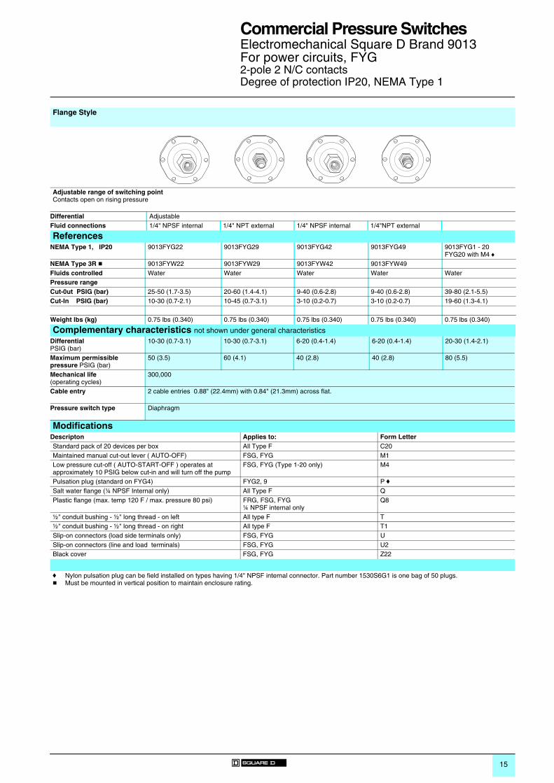
Electromechanical Square D Brand 9013For power circuits, FYG2-pole 2 N/C contactsDegree of protection IP20, NEMA Type 1
Flange Style
Adjustable range of switching point Contacts open on rising pressure
Differential AdjustableFluid connections 1/8" NPSF internal 1/4" NPSF internal 1/4" NPT external 1/4" Bayonet (barbed) 90 ° Elbow ¼" Bayonet
ReferencesNEMA Type 1, IP20 9013FYG1 9013FYG2 9013FYG9 9013FYG10 9013FYG20NEMA Type 3R c 9013FYW1 9013FYW2 9013FYW9 9013FYW10 9013FYW20Fluids controlled Water Water Water Water WaterPressure rangeCut-0ut PSIG (bar) 25-80 (1.7-5.5) 25-80 (1.7-5.5) 25-80 (1.7-5.5) 25-80 (1.7-5.5) 25-80 (1.7-5.5)Cut-In PSIG (bar) 5-60 (0.3-4.1) 5-60 (0.3-4.1) 5-60 (0.3-4.1) 5-60 (0.3-4.1) 5-60 (0.3-4.1)
Weight lbs (kg) 0.75 lbs (0.340) 0.75 lbs (0.340) 0.75 lbs (0.340) 0.75 lbs (0.340) 0.75 lbs (0.340)
Complementary characteristics not shown under general characteristics DifferentialPSIG (bar)
20-30 (1.4-2.1)
Maximum permissible pressure PSIG (bar)
80 (5.5)
Mechanical life 300, 000 operating cycles
Cable entry 2 cable entries 0.88" (22.4mm) with 0.84" (21.3mm) across flat.
Pressure switch type Diaphragm
Ordering Information Pressure Codes
1 Specify Class 9013 Type FYG.2 Select pressure code and add code designation to end of type
number. Be sure that pressure code falls within the limits of the device as shown in the device listings.
3 If special features are desired, add the appropriate Form letter to the Class and Type. Arrange Form letters in alphabetical sequence when ordering more than one special feature.
4 Place packaging code at end of sequence with other forms when ordering. If no packaging code is indicated, devices will be shipped individually packaged.For standard pack of 20 devices per box C20Example: 9013FYG2J21C20
Below is the pressure code table. Existence of a code does not imply that the code is available for any or all devices.Settings Code5-21 PSI J158-20 PSI J1620-40 PSI J2020-50 PSI J1830-50 PSI J2140-60 PSI J2450-70 PSI J3355-85 PSI J3460-80 PSI J25Specify pressure setting J99
c Must be mounted in vertical position to maintain enclosure rating.
15
Commercial Pressure Switches 0
Electromechanical Square D Brand 9013For power circuits, FYG2-pole 2 N/C contactsDegree of protection IP20, NEMA Type 1
Flange Style
Adjustable range of switching point Contacts open on rising pressure
Differential AdjustableFluid connections 1/4" NPSF internal 1/4" NPT external 1/4" NPSF internal 1/4"NPT external
ReferencesNEMA Type 1, IP20 9013FYG22 9013FYG29 9013FYG42 9013FYG49 9013FYG1 - 20
FYG20 with M4 ♦NEMA Type 3R c 9013FYW22 9013FYW29 9013FYW42 9013FYW49Fluids controlled Water Water Water Water WaterPressure rangeCut-0ut PSIG (bar) 25-50 (1.7-3.5) 20-60 (1.4-4.1) 9-40 (0.6-2.8) 9-40 (0.6-2.8) 39-80 (2.1-5.5)Cut-In PSIG (bar) 10-30 (0.7-2.1) 10-45 (0.7-3.1) 3-10 (0.2-0.7) 3-10 (0.2-0.7) 19-60 (1.3-4.1)
Weight lbs (kg) 0.75 lbs (0.340) 0.75 lbs (0.340) 0.75 lbs (0.340) 0.75 lbs (0.340) 0.75 lbs (0.340)
Complementary characteristics not shown under general characteristics DifferentialPSIG (bar)
10-30 (0.7-3.1) 10-30 (0.7-3.1) 6-20 (0.4-1.4) 6-20 (0.4-1.4) 20-30 (1.4-2.1)
Maximum permissible pressure PSIG (bar)
50 (3.5) 60 (4.1) 40 (2.8) 40 (2.8) 80 (5.5)
Mechanical life(operating cycles)
300,000
Cable entry 2 cable entries 0.88" (22.4mm) with 0.84" (21.3mm) across flat.
Pressure switch type Diaphragm
Modifications Descripton Applies to: Form LetterStandard pack of 20 devices per box All Type F C20Maintained manual cut-out lever ( AUTO-OFF) FSG, FYG M1Low pressure cut-off ( AUTO-START-OFF ) operates at approximately 10 PSIG below cut-in and will turn off the pump
FSG, FYG (Type 1-20 only) M4
Pulsation plug (standard on FYG4) FYG2, 9 P fSalt water flange (¼ NPSF Internal only) All Type F QPlastic flange (max. temp 120 F / max. pressure 80 psi) FRG, FSG, FYG
¼ NPSF internal onlyQ8
½" conduit bushing - ½" long thread - on left All type F T½" conduit bushing - ½" long thread - on right All type F T1Slip-on connectors (load side terminals only) FSG, FYG USlip-on connectors (line and load terminals) FSG, FYG U2Black cover FSG, FYG Z22
f Nylon pulsation plug can be field installed on types having 1/4" NPSF internal connector. Part number 1530S6G1 is one bag of 50 plugs.c Must be mounted in vertical position to maintain enclosure rating.

16
References, characteristics
Commercial Pressure Switches 0
Electromechanical Square D Brand 9013For power circuits, FRG1 or 2-pole 2 N/O contacts Degree of protection IP20, NEMA Type 1
Flange Style
Adjustable range of switching point Contacts open on falling pressure
Differential Adjustable Fluid connections 1/4" NPSF internal 3/8" NPSF internal 1/4" Flare 1/4" NPT external 1/4" NPSF internal 3/8" NPSF internal
ReferencesNEMA Type 1, IP20 1 pole 9013FRG12 9013FRG13 9013FRG18 9013FRG19 9013FRG32 9013FRG33NEMA Type 1, IP20 2 pole 9013FRG2 9013FRG3 9013FRG8 9013FRG9 9013FRG22 9013FRG23Fluids controlled Water Water Water Water Water WaterPressure rangeCut-0ut PSIG (bar) 8-45 (0.6-3.1) 8-45 (0.6-3.1) 8-45 (0.6-3.1) 8-45 (0.6-3.1) 4-25 (0.3-1.7) 4-25 (0.3-1.7)Cut-In PSIG (bar) 23-65 (1.6-4.5) 23-65 (1.6-4.5) 23-65 (1.6-4.5) 23-65 (1.6-4.5) 10-45 (0.7-3.1) 10-45 (0.7-3.1)
Weight lbs (kg) 0.75 lbs (0.340) 0.75 lbs (0.340) 0.75 lbs (0.340) 0.75 lbs (0.340) 0.75 lbs (0.340) 0.75 lbs (0.340)
Complementary characteristics not shown under general characteristics DifferentialPSIG (bar)
15-30 (1.0-2.1) 15-30 (1.0-2.1) 15-30 (1.0-2.1) 15-30 (1.0-2.1) 6-20 (0.4-1.4) 6-20 (0.4-1.4)
Maximum permissible pressure PSIG (bar)
65 (4.5) 65 (4.5) 65 (4.5) 65 (4.5) 45 (3.1) 45 (3.1)
Mechanical life 300, 000 operating cycles
Cable entry 2 cable entries 0.88" (22.4mm) with 0.84" (21.3mm) across flat.
Pressure switch type Diaphragm
Ordering Information Pressure Codes
1 Specify Class 9013 Type FRG.2 Select pressure code and add code designation to end of type
number. Be sure that pressure code falls within the limits of the device as shown in the device listings.
3 If special features are desired, add the appropriate Form letter to the Class and Type. Arrange Form letters in alphabetical sequence when ordering more than one special feature.
4 Place packaging code at end of sequence with other forms when ordering. If no packaging code is indicated, devices will be shipped individually packaged.For standard pack of 20 devices per box C20Example: 9013FRG19M3J23C20
Below is the pressure code table. Existence of a code does not imply that the code is available for any or all devices.Settings Code8.5-5.5 PSI J1710-5 PSI J3622-12 PSI J2222-16 PSI J1935-20 PSI J7040-20 PSI J2350-30 PSI J3580-60 PSI J32100-80 PSI J51150-120 J64Specify pressure setting J99

17
Commercial Pressure Switches 0
Electromechanical Square D Brand 9013For power circuits, FRG1 or 2-pole 2 N/O contacts Degree of protection IP20, NEMA Type 1
Flange Style
Adjustable range of switching point Contacts open on falling pressure
Differential Adjustable w Non-adjustableFluid connections 1/4" Flare 1/4" NPT external 1/4" NPSF internal 3/8" NPSF internal 1/4" Flare 1/4" NPT external
ReferencesNEMA Type 1, IP20 1 pole 9013FRG38 9013FRG39 9013FRG52 w 9013FRG53 w 9013FRG58 w 9013FRG59 wNEMA Type 1, IP20 2 pole 9013FRG28 9013FRG29 9013FRG42 w 9013FRG43 w 9013FRG48 w 9013FRG49 wFluids controlled Water Water Water Water Water WaterPressure rangeCut-0ut PSIG (bar) 4-25 (0.3-1.7) 4-25 (0.3-1.7) 1-11 (0.1-0.8) 1-11 (0.1-0.8) 1-11 (0.1-0.8) 1-11 (0.1-0.8)Cut-In PSIG (bar) 10-45 (0.7-3.1) 10-45 (0.7-3.1) 6-14 (0.4-1.0) 6-14 (0.4-1.0) 6-14 (0.4-1.0) 6-14 (0.4-1.0)
Weight lbs (kg) 0.75 lbs (0.340) 0.75 lbs (0.340) 0.75 lbs (0.340) 0.75 lbs (0.340) 0.75 lbs (0.340) 0.75 lbs (0.340)
Complementary characteristics not shown under general characteristics DifferentialPSIG (bar)
6-20 (0.4-1.4) 6-20 (0.4-1.4) 5 (0.3) 5 (0.3) 5 (0.3) 5 (0.3)
Maximum permissible pressure PSIG (bar)
45 (3.1) 45(3.1) 14 (1.0) 14 (1.0) 14 (1.0) 14 (1.0)
Mechanical life(operating cycles)
300,000
Cable entry 2 cable entries 0.88" (22.4mm) with 0.84" (21.3mm) across flat.
Pressure switch type Diaphragm
ModificationsDescripton Applies to: Form LetterStandard pack of 20 devices per box All Type F C20One normally open / One normally closed contact FRG (2 pole only) HMomentary manual cut-in lever ( AUTO-START ) FRG2-59 only M3Maintained manual cut-in lever ( AUTO-ON) FRG2-59 only M5Pulsation plug FRG2, 9 P fSalt water flange (¼ NPSF Internal only) All Type F QPlastic flange (max. temp 120 F / maz. pressure 80 psi) FRG, FSG, FYG Q8
¼ NPSF internal only½" conduit bushing - ½" long thread - on left All type F T½" conduit bushing - ½" long thread - on right All type F T1Black cover FSG, FYG, FRG Z22
f Nylon pulsation plug can be field installed on types having 1/4" NPSF internal connector. Part number 1530S6G1 is one bag of 50 plugs.

18
References, characteristics
Commercial Pressure Switches 0
Electromechanical Square D Brand 9013For power circuits, FRG1 or 2-pole 2 N/O contacts Degree of protection IP20, NEMA Type 1
Flange Style
Adjustable range of switching point Contacts open on falling pressure
Differential Adjustable Fluid connections 1/4" NPSF internal 3/8" NPSF internal 1/4" Flare 1/4" NPSF internal 3/8" NPSF internal 1/4" Flare
ReferencesNEMA Type 1, IP20 1 pole 9013FRG72 9013FRG73 9013FRG78 9013FRG92 9013FRG93 9013FRG98NEMA Type 1, IP20 2 pole 9013FRG62 9013FRG63 9013FRG68 9013FRG82 9013FRG83 9013FRG88Fluids controlled Water Water Water Water Water WaterPressure rangeCut-0ut PSIG (bar) 20-75 (1.4-5.2) 20-75 (1.4-5.2) 20-75 (1.4-5.2) 35-120 (2.4-8.3) 35-120 (2.4-8.3) 35-120 (2.4-8.3)Cut-In PSIG (bar) 40-100 (2.8-6.9) 40-100 (2.8-6.9) 40-100 (2.8-6.9) 65-150 (4.5-10.3) 65-150 (4.5-10.3) 65-150 (4.5-10.3)
Weight lbs (kg) 0.75 lbs (0.340) 0.75 lbs (0.340) 0.75 lbs (0.340) 0.75 lbs (0.340) 0.75 lbs (0.340) 0.75 lbs (0.340)
Complementary characteristics not shown under general characteristics DifferentialPSIG (bar)
20-30 (1.4-2.1) 20-30 (1.4-2.1) 20-30 (1.4-2.1) 30-45 (2.1-3.1) 30-45 (2.1-3.1) 30-45 (2.1-3.1)
Maximum permissible pressure PSIG (bar)
100 (6.9) 100 (6.9) 100 (6.9) 150 (10.3) 150 (10.3) 150 (10.3)
Mechanical life 300, 000 operating cycles
Cable entry 2 cable entries 0.88" (22.4mm) with 0.84" (21.3mm) across flat.
Pressure switch type Diaphragm
Ordering Information Pressure Codes
1 Specify Class 9013 Type FRG.2 Select pressure code and add code designation to end of type
number. Be sure that pressure code falls within the limits of the device as shown in the device listings.
3 If special features are desired, add the appropriate Form letter to the Class and Type. Arrange Form letters in alphabetical sequence when ordering more than one special feature. If no packaging code is indicated, devices will be shipped individually packaged.
4 Place packaging code at end of sequence with other forms when ordering.For standard pack of 20 devices per box C20For individual packaged devices leave blankExample: 9013FRG72J23C20
Below is the pressure code table. Existence of a code does not imply that the code is available for any or all devices.Settings Code8.5-5.5 PSI J1710-5 PSI J3622-12 PSI J2222-16 PSI J1935-20 PSI J7040-20 PSI J2350-30 PSI J3580-60 PSI J32100-80 PSI J51150-120 J64Specify pressure setting J99
19
Commercial Pressure Switches 0
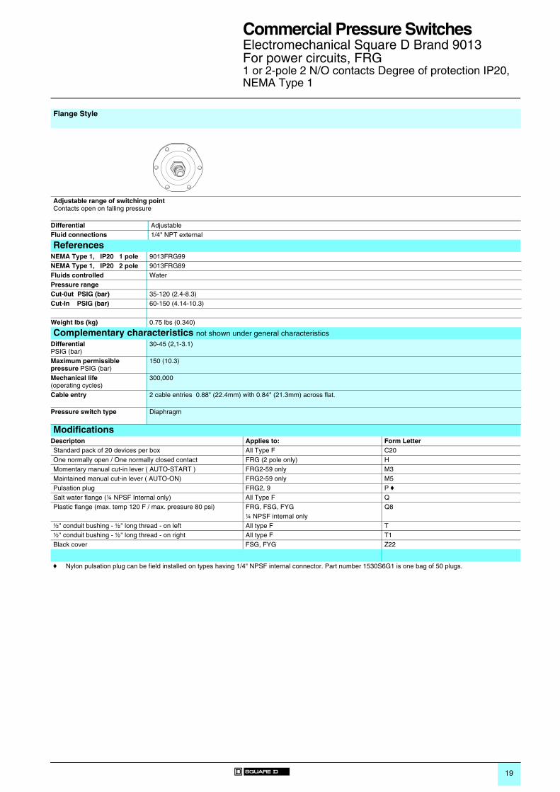
Electromechanical Square D Brand 9013For power circuits, FRG1 or 2-pole 2 N/O contacts Degree of protection IP20, NEMA Type 1
Flange Style
Adjustable range of switching point Contacts open on falling pressure
Differential AdjustableFluid connections 1/4" NPT external
ReferencesNEMA Type 1, IP20 1 pole 9013FRG99NEMA Type 1, IP20 2 pole 9013FRG89Fluids controlled WaterPressure rangeCut-0ut PSIG (bar) 35-120 (2.4-8.3)Cut-In PSIG (bar) 60-150 (4.14-10.3)
Weight lbs (kg) 0.75 lbs (0.340)
Complementary characteristics not shown under general characteristics DifferentialPSIG (bar)
30-45 (2,1-3.1)
Maximum permissible pressure PSIG (bar)
150 (10.3)
Mechanical life(operating cycles)
300,000
Cable entry 2 cable entries 0.88" (22.4mm) with 0.84" (21.3mm) across flat.
Pressure switch type Diaphragm
ModificationsDescripton Applies to: Form LetterStandard pack of 20 devices per box All Type F C20One normally open / One normally closed contact FRG (2 pole only) HMomentary manual cut-in lever ( AUTO-START ) FRG2-59 only M3Maintained manual cut-in lever ( AUTO-ON) FRG2-59 only M5Pulsation plug FRG2, 9 P fSalt water flange (¼ NPSF Internal only) All Type F QPlastic flange (max. temp 120 F / max. pressure 80 psi) FRG, FSG, FYG Q8
¼ NPSF internal only½" conduit bushing - ½" long thread - on left All type F T½" conduit bushing - ½" long thread - on right All type F T1Black cover FSG, FYG Z22
f Nylon pulsation plug can be field installed on types having 1/4" NPSF internal connector. Part number 1530S6G1 is one bag of 50 plugs.

20
References, characteristics
Commercial Pressure Switches 0
Electromechanical Square D Brand 9013For power circuits FHG, Compressor2-pole 2 N/C contactsDegree of protection IP20, NEMA Type 1
Flange Style
Adjustable range of switching point Contacts open on rising pressure
Differential Non-adjustablePressure connections 1/4" NPSF internal 3/8" NPSF internal 1/4" 4 way flange 1/4" NPT external 1/4" NPSF internal 3/8" NPSF internal
ReferencesNEMA Type 1, IP20 - 2 pole - Lower hp
9013FHG2 9013FHG3 9013FHG44 9013FHG9 9013FHG12 9013FHG13
NEMA Type 1, IP20 - 2 pole -Higher hp
9013FHG22 — 9013FHG24 9013FHG29 9013FHG32 9013FHG33
Controls Air Air Air Air Air AirPressure rangeAdjustable Cut-0ut PSIG (bar) 40-100 (2.8-6.9) 40-100 (2.8-6.9) 40-100 (2.8-6.9) 40-100 (2.8-6.9) 70-150 (4.8-10.3) 70-100 (4.8-10.3)
Weight lbs (kg) 0.75 lbs (0.340) 0.75 lbs (0.340) 0.75 lbs (0.340) 0.75 lbs (0.340) 0.75 lbs (0.340) 0.75 lbs (0.340)
Complementary characteristics not shown under general characteristics DifferentialPSIG (bar) Non-adjustable
20 (1.4) 20 (1.4) 20 (1.4) 20 (1.4) 30 (2.1) 30 (2.1)
Maximum permissible pressure PSIG (bar)
100 (6.9) 100 (6.9) 100 (6.9) 100 (6.9) 150 (10.3) 150 (10.3)
Mechanical life 300, 000 operating cycles
Cable entry 2 cable entries 0.88" (22.4mm) with 0.84" (21.3mm) across flat.
Pressure switch type Diaphragm
Ordering Information Pressure Codes
1 Specify Class 9013 Type FHG.2 Select pressure code and add code designation to end of type
number. Be sure that pressure code falls within the limits of the device as shown in the device listings.
3 If special features are desired, add the appropriate Form letter to the Class and Type. Arrange Form letters in alphabetical sequence when ordering more than one special feature. If no packaging code is indicated, devices will be shipped individually packaged.
4 Place packaging code at end of sequence with other forms when ordering.For standard pack of 20 devices per box C20Example: 9013FHG19J52MIXC20
Below is the pressure code table. Existence of a code does not imply that the code is available for any or all devices.Settings CodeOff at 100 PSI J27Off at 110 PSI J37Off at 115 PSI J38Off at 120 PSI J69Off at 125 PSI J52Off at 135 PSI J39Off at 140 PSI J68Off at 150 PSI J55Off at 155 PSI J40Off at 175 PSI J59Specify pressure setting J99

21
Commercial Pressure Switches 0
Electromechanical Square D Brand 9013For power circuits FHG, Compressor2-pole 2 N/C contactsDegree of protection IP20, NEMA Type 1
Flange Style
Adjustable range of switching point Contacts open on rising pressure
Differential Non-adjustablePressure connections Four way flange 1/4" NPT external 1/4" NPSF internal Four way flange 1/4" NPT external
ReferencesNEMA Type 1, IP20 - 2 pole - Lower hp 9013FHG14 9013FHG19 9013FHG42 9013FHG44 9013FHG49NEMA Type 1, IP20 - 2 pole - Higher hp
9013FHG34 9013FHG39 9013FHG52 9013FHG54 9013FHG59
Controls Air Air Air Air AirPressure rangeAdjustable Cut-0ut PSIG (bar) 70-150 (4.8-10.3) 70-150 (4.8-10.3) 100-200 (6.9-13.8) 100-200 (6.9-13.8) 100-200 (6.9-13.8)
Weight lbs (kg) 0.75 lbs (0.340) 0.75 lbs (0.340) 0.75 lbs (0.340) 0.75 lbs (0.340) 0.75 lbs (0.340)
Complementary characteristics not shown under general characteristics DifferentialPSIG (bar) Non-adjustable
30 (2.1) 30 (2.1) 40 (2.8) 40 (2.8) 40 (2.8)
Maximum permissible pressure PSIG (bar)
150 (10.3) 150 (10.3) 200 (13.8) 200 (13.8) 200 (13.8)
Mechanical life(operating cycles)
300,000
Cable entry 2 cable entries 0.88" (22.4mm) with 0.84" (21.3mm) across flat.
Pressure switch type Diaphragm
ModificationsDescripton Form LetterStandard pack of 20 devices per box C20Addition of a second ground screw G4 Maintained manual cut-out lever ( AUTO-OFF) M1Pulsation plug (copper) P (not field installable)½" conduit bushing - ½" long thread - on left T½" conduit bushing - ½" long thread - on right T1Slip-on connections (load side terminals only) USlip-on connectors (line and load terminals) U2Factory sealed range stud WTwo-way pressure release valve XQuick connect two-way pressure release valve (for use with Polyflow Tubing)
X1
Black cover Z22

22
References, characteristics
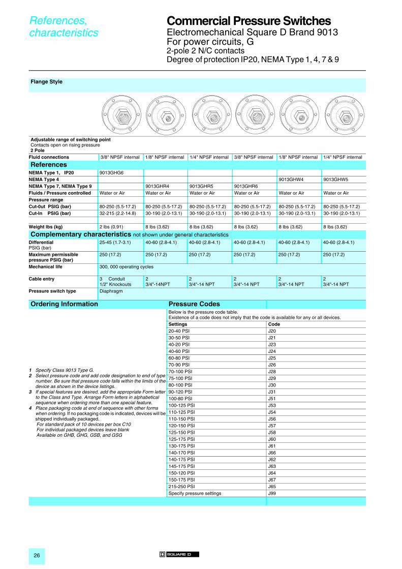
Commercial Pressure Switches 0
Electromechanical Square D Brand 9013For power circuits, G2-pole 2 N/C contactsDegree of protection IP20, NEMA Type 1, 3R, 7 & 9
Flange Style
Adjustable range of switching point Contacts open on rising pressure2 Pole
Fluid connections 1/4" NPSF internal 1/4" NPSF internal 1/8" NPSF internal 1/4" NPSF internal 3/8" NPSF internal 1/8" NPSF internal
ReferencesNEMA Type 1, IP20 9013GMG2 9013GSG1 9013GSG2 9013GSG3NEMA Type 3R c 9013GSB2NEMAType 7, NEMA Type 9 9013GSR1Fluids / Pressure controlled Water or Air Water or Air Water or Air Water or Air Water or Air Water or AirPressure rangeCut-0ut PSIG (bar) 10-35 (0.7-2.4) 20-80 (1.4-5.5) 20-80 (1.4-5.5) 20-80 (1.4-5.5) 20-80 (1.4-5.5) 20-80 (1.4-5.5)Cut-In PSIG (bar) 5.5-30.5 (0.4-2.1) 5-60 (0.4-4.1) 5-60 (0.4-4.1) 5-60 (0.4-4.1) 5-60 (0.4-4.1) 5-50 (0.4-4.1)
Weight lbs (kg) 2 lbs (0.91) 2 lbs (0.91) 2 lbs (0.91) 2 lbs (0.91) 2 lbs (0.91) 8 lbs (3.62)
Complementary characteristics not shown under general characteristics DifferentialPSIG (bar)
4-8 (0.3-0.6) 15-30 (1.0-2.1) 15-30 (1.0-2.1) 15-30 (1.0-2.1) 15-30 (1.0-2.1) 20-40 (1.4-2.8)
Maximum permissible pressure PSIG (bar)
35 (2.4) 80 (5.5) 80 (5.5) 80 (5.5) 80 (5.5) 80 (5.5)
Mechanical life 300, 000 operating cycles
Cable entry 3 Conduit1/2" Knockouts
3 Conduit1/2" Knockouts
3 Conduit1/2" Knockouts
3 Conduit1/2" Knockouts
3 Conduit1/2" Knockouts
2 3/4"-14NPT
Pressure switch type Diaphragm
Ordering Information Pressure Codes
1 Specify Class 9013 Type G.2 Select pressure code and add code designation to end of type
number. Be sure that pressure code falls within the limits of the device as shown in the device listings.
3 If special features are desired, add the appropriate Form letter to the Class and Type. Arrange Form letters in alphabetical sequence when ordering more than one special feature.
4 Place packaging code at end of sequence with other forms when ordering. If no packaging code is indicated, devices will be shipped individually packaged.For standard pack of 10 devices per box C10Available on GHB, GHG, GSB, and GSG
See page 23 for Form C10.
Below is the pressure code table. Existence of a code does not imply that the code is available for any or all devices.Settings Code20-40 PSI J2030-50 PSI J2140-20 PSI J2340-60 PSI J2460-80 PSI J2570-90 PSI J2670-100 PSI J2875-100 PSI J2980-100 PSI J3090-120 PSI J31100-80 PSI J51100-125 PSI J53110-125 PSI J54110-150 PSI J56120-150 PSI J57125-150 PSI J58125-175 PSI J60130-175 PSI J61140-170 PSI J66140-175 PSI J62145-175 PSI J63150-120 PSI J64150-175 PSI J67215-250 PSI J65Specify pressure setting J99
c Must be mounted in vertical position to maintain enclosure rating.

23
Commercial Pressure Switches 0
Electromechanical Square D Brand 9013For power circuits, G2-pole 2 N/C contactsDegree of protection IP20, NEMA Type 3R, 4, 7 & 9
Flange Style
Adjustable range of switching point Contacts open on rising pressure
Fluid connections 1/4" NPSF internal 3/8" NPSF internal 1/8" NPSF internal 1/4" NPSF internal 3/8" NPSF internal 1/4" NPSF internal
ReferencesNEMA Type 3R 9013GHB2NEMA Type 4 9013GSW1 9013GSW2 9013GSW3NEMA Type 7, NEMA Type 9 9013GSR2 9013GSR3Fluids / Pressure controlled Water or Air Water or Air Water or Air Water or Air Water or Air Water or AirPressure rangeCut-0ut PSIG (bar) 20-80 20-80 20-80 20-80 20-80 60-200Cut-In PSIG (bar) 5-50 5-50 5-50 5-50 5-50 40-170
Weight lbs (kg) 8 lbs (3.62) 8 lbs (3.62) 8 lbs (3.62) 8 lbs (3.62) 8 lbs (3.62) 2 lbs (0.91)
Complementary characteristics not shown under general characteristics DifferentialPSIG (bar)
20-40 (1.4-2.8) 20-40 (1.4-2.8) 20-40 (1.4-2.8) 20-40 (1.4-2.8) 20-40 (1.4-2.8) 20-40 (1.4-2.8)
Maximum permissible pressure PSIG (bar)
80 (5.5) 80 (5.5) 80 (5.5) 80 (5.5) 80 (5.5) 200 (13.8)
Mechanical life(operating cycles)
300,000
Cable entry 2 3/4"-14 NPT
2 3/4"-14 NPT
2 3/4"-14 NPT
2 3/4"-14 NPT
2 3/4"-14 NPT
3 Conduit1/2" Knockouts
Pressure switch type Diaphragm
ModificationsDescripton Applies to: Form LetterStandard pack of 10 devices per box GHB, GHG, GSB, GSG C103-Way lever (On-Auto-Off) not compatible with Form X GHG, GMG, GSG EOne normally open / One normally closed contact All type G H lPulsation plug (copper) All type G P (not field installable)Reverse action / Two normally open contacts All type G R lSlip-on connectors (load side terminals only) All type G USlip-on connectors (line and load terminals) All type G U22-Way pressure release valve (not compatible with Form E) GHB, GMG, GSB, GHG, GSG, GHR, GHW,
GSR, GSWX
¼" Male pipe thread on pressure connection All type G Z½" - 14 NPT external¼" - 18 NPT internal
All type G Z16
3/8" Male pipe thread on pressure connection All type G Z23
l Cannot order Form R when ordering Form H

24
References, characteristics
Commercial Pressure Switches 0
Electromechanical Square D Brand 9013For power circuits G2-pole 2 N/C contactsDegree of protection IP20, NEMA Type 1, 7 & 9
Flange Style
Adjustable range of switching point Contacts open on rising pressure2 Pole
Fluid connections 1/8" NPSF internal 1/4" NPSF internal 3/8" NPSF internal 1/8" NPSF internal 1/4" NPSF internal 3/8" NPSF internal
ReferencesNEMA Type 1, IP20 9013GHG1 9013GHG2 9013GHG3NEMA Type 7, NEMA Type 9 9013GHR1 9013GHR2 9013GHR3Fluids / Pressure controlled Water or Air Water or Air Water or Air Water or Air Water or Air Water or AirPressure rangeCut-0ut PSIG (bar) 60-200 60-200 60-200 65-200 65-200 65-200Cut-In PSIG (bar) 40-170 40-170 40-170 35-150 35-150 35-150
Weight lbs (kg) 2 lbs (0.91) 2 lbs (0.91) 2 lbs (0.91) 8 lbs (3.62) 8 lbs (3.62) 8 lbs (3.62)
Complementary characteristics not shown under general characteristics DifferentialPSIG (bar)
20-40 (1.4-2.8) 20-40 (1.4-2.8) 20-40 (1.4-2.8) 30-50 (2.1-3.5) 30-50 (2.1-3.5) 30-50 (2.1-3.5)
Maximum permissible pressure PSIG (bar)
80 (5.5) 80 (5.5) 80 (5.5) 80 (5.5) 80 (5.5) 200 (13.8)
Mechanical life 300, 000 operating cycles
Cable entry 3 Conduit1/2" Knockouts
3 Conduit1/2" Knockouts
3 Conduit1/2" Knockouts
2 3/4"-14 NPT
2 3/4"-14 NPT
2 3/4"-14 NPT
Pressure switch type Diaphragm
Ordering Information Pressure Codes
1 Specify Class 9013 Type G.2 Select pressure code and add code designation to end of type
number. Be sure that pressure code falls within the limits of the device as shown in the device listings.
3 If special features are desired, add the appropriate Form letter to the Class and Type. Arrange Form letters in alphabetical sequence when ordering more than one special feature.
4 Place packaging code at end of sequence with other forms when ordering. If no packaging code is indicated, devices will be shipped individually packaged.For standard pack of 10 devices per box C10Available on GHB, GHG, GSB, and GSG
See page 25 for Form C10.
Below is the pressure code table. Existence of a code does not imply that the code is available for any or all devices.Settings Code20-40 PSI J2030-50 PSI J2140-20 PSI J2340-60 PSI J2460-80 PSI J2570-90 PSI J2670-100 PSI J2875-100 PSI J2980-100 PSI J3090-120 PSI J31100-80 PSI J51100-125 PSI J53110-125 PSI J54110-150 PSI J56120-150 PSI J57125-150 PSI J58125-175 PSI J60130-175 PSI J61140-170 PSI J66140-175 PSI J62145-175 PSI J63150-120 PSI J64150-175 PSI J67215-250 PSI J65Specify pressure settings J99

25
Commercial Pressure Switches 0
Electromechanical Square D Brand 9013For power circuits, G2-pole 2 N/C contactsDegree of protection IP20, NEMA Type 1, 3R, & 4
Flange Style
Adjustable range of switching point Contacts open on rising pressure2 Pole
Fluid connections 1/8" NPSF internal 1/4" NPSF internal 3/8" NPSF internal 1/4" NPSF internal 1/8" NPSF internal 1/4" NPSF internal
ReferencesNEMA Type 1, IP20 9013GHG4 9013GHG5NEMA Type 3R 9013GHB5NEMA Type 4 9013GHW1 9013GHW2 9013GWG3Fluids / Pressure controlled Water or Air Water or Air Water or Air Water or Air Water or Air Water or AirPressure rangeCut-0ut PSIG (bar) 65-200 (4.5-13.8) 65-200 (4.5-13.8) 65-200 (4.5-13.8) 80-250 (5.5-17.2) 80-250 (5.5-17.2) 80-250 (5.5-17.2)Cut-In PSIG (bar) 35-150 (2.4-10.3) 35-150 (2.4-10.3) 35-150 (2.4-10.3) 32-215 (2.2-14.8) 32-215 (2.2-14.8) 32-215 (2.2-14.8)
Weight lbs (kg) 8 lbs (3.62) 8 lbs (3.62) 8 lbs (3.62) 2 lbs (0.91) 2 lbs (0.91) 2 lbs (0.91)
Complementary characteristics not shown under general characteristics DifferentialPSIG (bar)
30-50 (2.1-3.5) 30-50 (2.1-3.5) 30-50 (2.1-3.5) 25-45 (1.7-3.1) 25-45 (1.7-3.1) 25-45 (1.7-3.1)
Maximum permissible pressure PSIG (bar)
200 (13.8) 200 (13.8) 200 (13.8) 250 (17.2) 250 (17.2) 250 (17.2)
Mechanical life(operating cycles)
300,000
Cable entry 2 3/4"-14 NPT
2 3/4"-14 NPT
2 3/4"-14 NPT
3 Conduit1/2" Knockouts
3 Conduit1/2" Knockouts
3 Conduit1/2" Knockouts
Pressure switch type Diaphragm
ModificationsDescripton Applies to: Form LetterStandard pack of 10 devices per box GHB, GHG, GSB, GSG C103-Way lever (On-Auto-Off) not compatible with Form X GHG, GMG, GSG EOne normally open / One normally closed contact All type G H lPulsation plug (copper) All type G P (not field installable)Reverse action / Two normally open contacts All type G R lSlip-on connectors (load side terminals only) All type G USlip-on connectors (line and load terminals) All type G U22-Way pressure release valve (not compatible with Form E) GHB, GMG, GSB, GHG, GSG, GHR, GHW,
GSR, GSWX
¼" Male pipe thread on pressure connection All type G Z½" - 14 NPT external¼" - 18 NPT internal
All type G Z16
3/8" Male pipe thread on pressure connection All type G Z23
l Cannot order Form R when ordering Form H
26
References, characteristics
Commercial Pressure Switches 0
Electromechanical Square D Brand 9013For power circuits, G2-pole 2 N/C contactsDegree of protection IP20, NEMA Type 1, 4, 7 & 9
Flange Style
Adjustable range of switching point Contacts open on rising pressure2 Pole
Fluid connections 3/8" NPSF internal 1/8" NPSF internal 1/4" NPSF internal 3/8" NPSF internal 1/8" NPSF internal 1/4" NPSF internal
ReferencesNEMA Type 1, IP20 9013GHG6NEMA Type 4 9013GHW4 9013GHW5NEMA Type 7, NEMA Type 9 9013GHR4 9013GHR5 9013GHR6Fluids / Pressure controlled Water or Air Water or Air Water or Air Water or Air Water or Air Water or AirPressure rangeCut-0ut PSIG (bar) 80-250 (5.5-17.2) 80-250 (5.5-17.2) 80-250 (5.5-17.2) 80-250 (5.5-17.2) 80-250 (5.5-17.2) 80-250 (5.5-17.2)Cut-In PSIG (bar) 32-215 (2.2-14.8) 30-190 (2.0-13.1) 30-190 (2.0-13.1) 30-190 (2.0-13.1) 30-190 (2.0-13.1) 30-190 (2.0-13.1)
Weight lbs (kg) 2 lbs (0.91) 8 lbs (3.62) 8 lbs (3.62) 8 lbs (3.62) 8 lbs (3.62) 8 lbs (3.62)
Complementary characteristics not shown under general characteristics DifferentialPSIG (bar)
25-45 (1.7-3.1) 40-60 (2.8-4.1) 40-60 (2.8-4.1) 40-60 (2.8-4.1) 40-60 (2.8-4.1) 40-60 (2.8-4.1)
Maximum permissible pressure PSIG (bar)
250 (17.2) 250 (17.2) 250 (17.2) 250 (17.2) 250 (17.2) 250 (17.2)
Mechanical life 300, 000 operating cycles
Cable entry 3 Conduit1/2" Knockouts
2 3/4"-14NPT
2 3/4"-14 NPT
2 3/4"-14 NPT
2 3/4"-14 NPT
2 3/4"-14 NPT
Pressure switch type Diaphragm
Ordering Information Pressure Codes
1 Specify Class 9013 Type G.2 Select pressure code and add code designation to end of type
number. Be sure that pressure code falls within the limits of the device as shown in the device listings.
3 If special features are desired, add the appropriate Form letter to the Class and Type. Arrange Form letters in alphabetical sequence when ordering more than one special feature.
4 Place packaging code at end of sequence with other forms when ordering. If no packaging code is indicated, devices will be shipped individually packaged.For standard pack of 10 devices per box C10For individual packaged devices leave blankAvailable on GHB, GHG, GSB, and GSG
Below is the pressure code table. Existence of a code does not imply that the code is available for any or all devices.Settings Code20-40 PSI J2030-50 PSI J2140-20 PSI J2340-60 PSI J2460-80 PSI J2570-90 PSI J2670-100 PSI J2875-100 PSI J2980-100 PSI J3090-120 PSI J31100-80 PSI J51100-125 PSI J53110-125 PSI J54110-150 PSI J56120-150 PSI J57125-150 PSI J58125-175 PSI J60130-175 PSI J61140-170 PSI J66140-175 PSI J62145-175 PSI J63150-120 PSI J64150-175 PSI J67215-250 PSI J65Specify pressure settings J99

27
Commercial Pressure Switches 0
Electromechanical Square D Brand 9013For power circuits, G2-pole 2 N/C contactsDegree of protection IP20, NEMA Type 4, 7, & 9
Diaphragm is included.
Flange Style
Adjustable range of switching point Contacts open on rising pressure2 Pole
Fluid connections 3/8" NPSF internal
ReferencesNEMA Type 4 9013GHW6NEMA Type 7, NEMA Type 9Fluids / Pressure controlled Water or AirPressure rangeCut-0ut PSIG (bar) 80-250 (5.5-17.2)Cut-In PSIG (bar) 30-190 (2.0-13.1)
Weight lbs (kg) 8 lbs (3.62)
Complementary characteristics not shown under general characteristics DifferentialPSIG (bar)
40-60 (2.8-4.1)
Maximum permissible pressure PSIG (bar)
250 (17.2)
Mechanical life(operating cycles)
300,000
Cable entry 2 3/4"-14 NPT
Pressure switch type Diaphragm
ModificationsDescripton Applies to: Form LetterStandard pack of 10 devices per box All Type G C103-Way lever (On-Auto-Off) not compatible with Form X GHG, GMG, GSG EOne normally open / One normally closed contact All type G H lPulsation plug (copper) All type G P (not field installable)Reverse action All type G R lSlip-on connectors (load side terminals only) All type G USlip-on connectors (line and load terminals) All type G U22-Way pressure release valve (not compatible with Form E) GHB, GMG, GSB, GHG, GSG, GHR, GHW,
GSR, GSWX
¼" Male pipe thread on pressure connection All type G Z½" - 14 NPT external¼" - 18 NPT internal
All type G Z16
3/8" Male pipe thread on pressure connection All type G Z23l Cannot order Form R when ordering Form H
Replacement contacts and diaphragmsDescripton 9998 Type:Repl. Contact Kit 9013GHG, GSG, GHR, GSR, GMG Series C, All except Forms H & R PC205Repl. Contact Kit 9013GHG, GSG, GSR, GMG; 9036GG, GR, GW; 9037GG, GR, GW Series C, Form H only; 9016GVG, Form H PC206Repl. Contact Kit 9013GHG, GSG, GHR, GSR, GMG; 9036GR, GW Series C, Form R only; 9016GVG PC207Convoluted Diaphragm Assy. 9013GHG, GSG Series C PC208Diaphragm Assy. 9013GMG Series C PC209Diaphragm Assy. 9013GHW, GSW, GSR, GHR Series C PC211Diaphragm Assy. 9013GHG, GSG PC252Repl. Contact Kit 9013FSG PC241 Repl. Contact Kit 9013FYG PC242 Repl. Contact Kit 9013FRG (2 pole) PC288 Repl. Contact Kit 9013FRG (1 pole) PC289 Repl. Contact Kit 9013FRG (Form H) PC290

28
Dimensions Commercial Pressure SwitchesElectromechanical Square D Brand 9013Compressor and Water Pump Pressure Switches
Type F PUMPTROL® Compressor and Water Pump Pressure Switches
A DimensionSwitch Type Inches mmFSG1, FYG1 1 1/32 26FHG2, 12, 22, 32, 42, 52, FRG2, FSG2, FYG2 29/32 23FHG3, 13, 33, FRG3, FSG3, FYG3 1 9/32 33FHG9, 19, 29, 39, 49, 59, FSG9, FYG9 1 3/32 28
Type G Compressor and Water Pump Pressure Switches
Switch TypeGHG, GSG - With or Without Form X
2.7871
0.308
0.308
0.5013
2.5064
2.8071
2.3459
1.5940
1.1930
0.7519
3.7696
A15/16 HEX
1/2 - 14 STRAIGHTPIPE THREAD
3.6899
3.8598
0.7318
1.2231
0.062
1.9951
1.09
281.9449
C65075-043
0.9424 2.05
52
0.297
(2) Wide Mtg Holes
0.8722
(3) Dia K.O.14 18 NPSF
Pipe Thread
NOTE: Mounting Bracket shown is availableas a Class 9049 Type A-52 Kit
3.7599
0.4211
5.72
145
2.0953
632.47
3.4487

29
Commercial Pressure SwitchesElectromechanical Square D Brand 9013Commercial, Light Industrial Pressure Switches
Type G Compressor and Water Pump Pressure Switches
Switch TypeGMG
6.17157
1.2532 2.50
64
0.297
14
(3)
(3)3.7595 18 NPSF
PIPE THREAD
DIA. HOLES
DIA. K.O.
2.3961
2.0352
0.9424
0.8722
2.3760
2.2256
1.0928
1.6742
0.7318
3.8598
NOTE: MOUNTING BRACKET SHOWN IS AVAILABLEAS A CLASS 9049 TYPE A-53 KIT.

30
Product Reference Index Commercial Pressure Switches 0
Numerics9013GHB2 . . . . . . . . 239013GSR1 . . . . . . . . 2290133GSR2 . . . . . . . 239013FHG2 . . . . . . . . 209013FHG12 . . . . . . . 209013FHG13 . . . . . . . 209013FHG14 . . . . . . . 219013FHG19 . . . . . . . 219013FHG22 . . . . . . . 209013FHG24 . . . . . . . 209013FHG29 . . . . . . . 209013FHG32 . . . . . . . 209013FHG33 . . . . . . . 209013FHG33 . . . . . . . 209013FHG34 . . . . . . . 219013FHG39 . . . . . . . 219013FHG42 . . . . . . . 219013FHG44 . . . . . . . 209013FHG44 . . . . . . . 219013FHG49 . . . . . . . 219013FHG52 . . . . . . . 219013FHG54 . . . . . . . 219013FHG59 . . . . . . . 219013FHG9 . . . . . . . . 209013FRG12 . . . . . . . 169013FRG13 . . . . . . . 169013FRG18 . . . . . . . 169013FRG19 . . . . . . . 169013FRG2 . . . . . . . . 169013FRG22 . . . . . . . 169013FRG23 . . . . . . . 169013FRG28 . . . . . . . 179013FRG29 . . . . . . . 179013FRG3 . . . . . . . . 169013FRG32 . . . . . . . 169013FRG33 . . . . . . . 169013FRG38 . . . . . . . 179013FRG39 . . . . . . . 179013FRG42 . . . . . . . 179013FRG43 . . . . . . . 179013FRG48 . . . . . . . 179013FRG49 . . . . . . . 179013FRG52 . . . . . . . 179013FRG53 . . . . . . . 179013FRG58 . . . . . . . 179013FRG59 . . . . . . . 179013FRG62 . . . . . . . 189013FRG63 . . . . . . . 189013FRG68 . . . . . . . 189013FRG72 . . . . . . . 189013FRG73 . . . . . . . 189013FRG78 . . . . . . . 189013FRG8 . . . . . . . . 169013FRG82 . . . . . . . 189013FRG83 . . . . . . . 189013FRG88 . . . . . . . 189013FRG89 . . . . . . . 199013FRG9 . . . . . . . . 169013FRG92 . . . . . . . 189013FRG93 . . . . . . . 189013FRG98 . . . . . . . 189013FRG99 . . . . . . . 199013FSG1 . . . . . . . . 109013FSG10 . . . . . . . 109013FSG1-20 w M4 .119013FSG2 . . . . . . . . 109013FSG20 . . . . . . . 10
9013FSG22 . . . . . . .119013FSG29 . . . . . . .119013FSG42 . . . . . . .119013FSG49 . . . . . . .119013FSG9 . . . . . . . .109013FSW1 . . . . . . . .109013FSW10 . . . . . . .109013FSW2 . . . . . . . .109013FSW20 . . . . . . .109013FSW22 . . . . . . .119013FSW29 . . . . . . .119013FSW42 . . . . . . .119013FSW49 . . . . . . .119013FSW9 . . . . . . . .109013FTG1 . . . . . . . . .129013FTG10 . . . . . . . .129013FTG2 . . . . . . . . .129013FTG20 . . . . . . . .129013FTG22 . . . . . . . .139013FTG29 . . . . . . . .139013FTG42 . . . . . . . .139013FTG49 . . . . . . . .139013FTG9 . . . . . . . . .129013FTW1 . . . . . . . .129013FTW10 . . . . . . .129013FTW2 . . . . . . . .129013FTW20 . . . . . . .129013FTW22 . . . . . . .139013FTW29 . . . . . . .139013FTW42 . . . . . . .139013FTW49 . . . . . . .139013FTW9 . . . . . . . .129013FYG1 . . . . . . . .149013FYG1-20 w M4 .159013FYG10 . . . . . . .149013FYG2 . . . . . . . .149013FYG20 . . . . . . .149013FYG22 . . . . . . .159013FYG29 . . . . . . .159013FYG42 . . . . . . .159013FYG49 . . . . . . .159013FYG9 . . . . . . . .149013FYW1 . . . . . . . .149013FYW10 . . . . . . .149013FYW2 . . . . . . . .149013FYW20 . . . . . . .149013FYW22 . . . . . . .159013FYW29 . . . . . . .159013FYW42 . . . . . . .159013FYW49 . . . . . . .159013FYW9 . . . . . . . .149013GHB5 . . . . . . . .259013GHG1 . . . . . . . .249013GHG2 . . . . . . . .249013GHG3 . . . . . . . .249013GHG4 . . . . . . . .259013GHG5 . . . . . . . .259013GHG6 . . . . . . . .269013GHR1 . . . . . . . .249013GHR2 . . . . . . . .249013GHR3 . . . . . . . .249013GHR4 . . . . . . . .269013GHR5 . . . . . . . .269013GHR6 . . . . . . . .269013GHW1 . . . . . . . .259013GHW2 . . . . . . . .259013GHW4 . . . . . . . .269013GHW5 . . . . . . . .26
9013GHW6 . . . . . . . .279013GMG2 . . . . . . . .229013GSB2 . . . . . . . .229013GSG1 . . . . . . . .229013GSG2 . . . . . . . .229013GSG3 . . . . . . . .229013GSR3 . . . . . . . .239013GSW1 . . . . . . . .239013GSW2 . . . . . . . .239013GSW3 . . . . . . . .239013GWG3 . . . . . . . .25


9013CT9701R6/06 January 2007
Schneider Electric Industries SAS
Headquarters
89, bd Franklin Roosevelt F - 92506 Rueil Malmaison Cedex
http://www.schneider-electric.com
Owing to changes in standards and equipment, the characteristics given in the text and images in this document are not binding until they have been confirmed with us.
Production : Schneider Electric IndustriesPhotos : Schneider Electric IndustriesPrinted by :
© 2006 Schneider Electric. All Rights Reserved.