8410d na operator manual en -...
TRANSCRIPT

8410D
*MM391*www.tennantco.com
Operator Manual
MM391Rev. 15 (05-2007)
North America / International
ES Extended Scrub SystemR
The Safe Scrubbing AlternativeR

This manual is furnished with each new model. It provides necessary operation and maintenance instructions.
Read this manual completely and understand the machine before operating or servicing it.
This machine will provide excellent service. However, the best results will be obtained at minimum costs if:
S The machine is operated with reasonable care.
S The machine is maintained regularly - per the machine maintenance instructions provided.
S The machine is maintained with manufacturer supplied or equivalent parts.
PROTECT THE ENVIRONMENTPlease dispose of packaging materials,old machine components such asbatteries, hazardous fluids such asantifreeze and oil, in an environmentallysafe way according to local wastedisposal regulations.
Always remember to recycle.
MACHINE DATAPlease fill out at time of installation for future reference.
Model No. --
Serial No. --
Machine Options --
Sales Rep. --
Sales Rep. phone no. --
Customer Number --
Installation Date --
Tennant CompanyPO Box 1452Minneapolis, MN 55440Phone: (800) 553--8033 or (763) 513--2850www.tennantco.com
CALIFORNIA PROPOSITION 65 WARNING:Engine exhaust from this product contains chemicals known to the State of California to cause cancer,birth defects, or other reproductive harm.
Thermo--Sentry and FaST--PAK are US registered and unregistered trademarks of Tennant Company.
Specifications and parts are subject to change without notice.
Copyright E 1996, 1997, 1999 -- 2006, 2007 TENNANT Company, Printed in U.S.A.

CONTENTS
18410D MM391 (6--05)
CONTENTS
PageSAFETY PRECAUTIONS 3. . . . . . . . . . . . . . . . .OPERATION 7. . . . . . . . . . . . . . . . . . . . . . . . . . . .
OPERATOR RESPONSIBILITY 7. . . . . . . . .MACHINE COMPONENTS 8. . . . . . . . . . . . .SYMBOL DEFINITIONS 9. . . . . . . . . . . . . . . .CONTROLS AND INSTRUMENTS 11. . . . . .OPERATION OF CONTROLS 12. . . . . . . . . .
DIRECTIONAL PEDAL 12. . . . . . . . . . . . . .BRAKE PEDAL 13. . . . . . . . . . . . . . . . . . . .PARKING BRAKE PEDAL 13. . . . . . . . . . .HAZARD LIGHT SWITCH (OPTION) 13. .OPERATING LIGHTS SWITCH 14. . . . . .FILTER SHAKER SWITCH 14. . . . . . . . . .HOPPER RAISE SWITCH 14. . . . . . . . . . .HOPPER DOOR SWITCH 15. . . . . . . . . . .HOPPER LOWER SWITCH 15. . . . . . . . .SIDE BRUSH SWITCH 15. . . . . . . . . . . . . .SWEEP VACUUM FAN SWITCH 16. . . . .MAIN SWEEP BRUSH SPEED
1 SWITCH 16. . . . . . . . . . . . . . . . . . . . . .MAIN SWEEP BRUSH SPEED
2 SWITCH 17. . . . . . . . . . . . . . . . . . . . . .CHARGING SYSTEM LIGHT 17. . . . . . . .ENGINE OIL PRESSURE LIGHT 18. . . . .ENGINE WATER TEMPERATURE
LIGHT 18. . . . . . . . . . . . . . . . . . . . . . . . . .MAINTENANCE MODE LIGHT 18. . . . . . .RECOVERY TANK FULL LIGHT 18. . . . .CLOGGED FILTER LIGHT 19. . . . . . . . . .HOPPER TEMPERATURE LIGHT --
THERMO SENTRY 19. . . . . . . . . . . . . .OK LIGHT 19. . . . . . . . . . . . . . . . . . . . . . . . .FUEL LEVEL GAUGE 20. . . . . . . . . . . . . . .HOURMETER 20. . . . . . . . . . . . . . . . . . . . .ES SWITCH (OPTION) 20. . . . . . . . . . . . . .DETERGENT FLOW SWITCH
(OPTION) 21. . . . . . . . . . . . . . . . . . . . . .EDGE SCRUB SWITCH 21. . . . . . . . . . . . .SCRUB SWITCH 22. . . . . . . . . . . . . . . . . . .SQUEEGEE SWITCH 23. . . . . . . . . . . . . . .THROTTLE LEVER 23. . . . . . . . . . . . . . . . .STEERING WHEEL 24. . . . . . . . . . . . . . . .HORN BUTTON 24. . . . . . . . . . . . . . . . . . . .IGNITION SWITCH 24. . . . . . . . . . . . . . . . .TURN SIGNAL SWITCH (OPTION) 25. . .STEERING COLUMN TILT HANDLE 25. .CIRCUIT BREAKERS 26. . . . . . . . . . . . . . .MAIN SWEEP BRUSH DOWN
PRESSURE KNOB 27. . . . . . . . . . . . . .SIDE BRUSH DOWN PRESSURE
KNOB 27. . . . . . . . . . . . . . . . . . . . . . . . . .SOLUTION FLOW SWITCH
(WITHOUT FaST) 27. . . . . . . . . . . . . . .SOLUTION FLOW SWITCH (FaST) 28. .FaST SWITCH 28. . . . . . . . . . . . . . . . . . . . .
PageLATCHES 29. . . . . . . . . . . . . . . . . . . . . . . . .FUSE 29. . . . . . . . . . . . . . . . . . . . . . . . . . . . .OPERATOR SEAT 30. . . . . . . . . . . . . . . . . .HOPPER SUPPORT BAR 30. . . . . . . . . . .
HOW THE MACHINE WORKS 31. . . . . . . . . .FaST SCRUBBING SYSTEM 32. . . . . . . . . . .PRE-OPERATION CHECKLIST 33. . . . . . . . .INSTALLING FaST PAK AGENT 34. . . . . . . .STARTING THE MACHINE 36. . . . . . . . . . . . .SWEEPING, SCRUBBING, AND BRUSH
INFORMATION 38. . . . . . . . . . . . . . . . . . . .SWEEPING 40. . . . . . . . . . . . . . . . . . . . . . . . . .STOP SWEEPING 41. . . . . . . . . . . . . . . . . . . .EMPTYING THE HOPPER 42. . . . . . . . . . . . .FILLING THE TANKS 44. . . . . . . . . . . . . . . . . .SCRUBBING 46. . . . . . . . . . . . . . . . . . . . . . . . .DOUBLE SCRUBBING 49. . . . . . . . . . . . . . . . .STOP SCRUBBING 49. . . . . . . . . . . . . . . . . . .DRAINING AND CLEANING THE TANKS 50STOP THE MACHINE 52. . . . . . . . . . . . . . . . .POST-OPERATION CHECKLIST 54. . . . . . . .ENGAGING HOPPER SUPPORT BAR 55. .DISENGAGING HOPPER SUPPORT BAR 56OPERATION ON INCLINES 57. . . . . . . . . . . .OPTIONS 58. . . . . . . . . . . . . . . . . . . . . . . . . . . .
VACUUM WAND (WET) 58. . . . . . . . . . . . .MACHINE TROUBLESHOOTING 61. . . . . . .
MAINTENANCE 64. . . . . . . . . . . . . . . . . . . . . . . . .MAINTENANCE CHART 64. . . . . . . . . . . . . . .LUBRICATION 66. . . . . . . . . . . . . . . . . . . . . . . .
ENGINE 66. . . . . . . . . . . . . . . . . . . . . . . . . . .REAR WHEEL SUPPORT 66. . . . . . . . . . .FRONT WHEEL BEARINGS 67. . . . . . . . .HOPPER LIFT ARM PIVOTS 67. . . . . . . .HOPPER DOOR PIVOTS 67. . . . . . . . . . .REAR SQUEEGEE CASTERS (for
machines below serialnumber 012215) 67. . . . . . . . . . . . . .
HYDRAULICS 68. . . . . . . . . . . . . . . . . . . . . . . .HYDRAULIC FLUID RESERVOIR 68. . . .HYDRAULIC FLUID 68. . . . . . . . . . . . . . . .HYDRAULIC HOSES 69. . . . . . . . . . . . . . .PROPELLING MOTOR 69. . . . . . . . . . . . . .
ENGINE 70. . . . . . . . . . . . . . . . . . . . . . . . . . . . .COOLING SYSTEM 70. . . . . . . . . . . . . . . .AIR FILTER INDICATOR 71. . . . . . . . . . . .AIR FILTER 71. . . . . . . . . . . . . . . . . . . . . . . .FUEL FILTER 72. . . . . . . . . . . . . . . . . . . . . .FUEL LINES 72. . . . . . . . . . . . . . . . . . . . . . .PRIMING THE FUEL SYSTEM 72. . . . . . .
BATTERY 73. . . . . . . . . . . . . . . . . . . . . . . . . . . .BELTS AND CHAINS 74. . . . . . . . . . . . . . . . . .
ENGINE BELT 74. . . . . . . . . . . . . . . . . . . . . .STATIC DRAG CHAIN 74. . . . . . . . . . . . . .

CONTENTS
8410D MM391 (6--05)2
PageDEBRIS HOPPER 75. . . . . . . . . . . . . . . . . . . . .
HOPPER DUST FILTER 75. . . . . . . . . . . . .REMOVING HOPPER DUST
FILTER 75. . . . . . . . . . . . . . . . . . . . . .THERMO SENTRY 77. . . . . . . . . . . . . . . . .
SCRUB HEAD 77. . . . . . . . . . . . . . . . . . . . . . . .BRUSHES 77. . . . . . . . . . . . . . . . . . . . . . . . . . . .
MAIN SWEEP BRUSH 77. . . . . . . . . . . . . .REPLACING MAIN SWEEP BRUSH 78CHECKING AND ADJUSTING MAIN
SWEEP BRUSH PATTERN 79. . . .SIDE BRUSH 81. . . . . . . . . . . . . . . . . . . . . . . . .
REPLACING SIDE BRUSH 82. . . . . . . . . .SIDE BRUSH GUARD 82. . . . . . . . . . . . . .
SCRUB BRUSHES 83. . . . . . . . . . . . . . . . . . . .REPLACING THE SCRUB BRUSHES 83
SOLUTION SYSTEM 84. . . . . . . . . . . . . . . . . .RECOVERY TANK 84. . . . . . . . . . . . . . . . .SOLUTION TANK 84. . . . . . . . . . . . . . . . . .FaST SYSTEM 85. . . . . . . . . . . . . . . . . . . . .
FaST SUPPLY HOSE CONNECTOR 85FaST SYSTEM FILTER SCREEN 85. .FaST SYSTEM AIR PUMP FILTER 85
SQUEEGEES 86. . . . . . . . . . . . . . . . . . . . . . . . .LEVELING THE REAR SQUEEGEE 86. .ADJUSTING REAR SQUEEGEE BLADE
DEFLECTION 87. . . . . . . . . . . . . . . . . . .SQUEEGEE BLADES 88. . . . . . . . . . . . . . . . .
REAR SQUEEGEE 88. . . . . . . . . . . . . . . . .REPLACING OR ROTATING REAR
SQUEEGEE BLADES 88. . . . . . . . .SIDE SQUEEGEES 89. . . . . . . . . . . . . . . .
REPLACING SIDE SQUEEGEEBLADES 89. . . . . . . . . . . . . . . . . . . . .
SKIRTS AND SEALS 90. . . . . . . . . . . . . . . . . .HOPPER LIP SKIRTS 90. . . . . . . . . . . . . . .HOPPER SIDE SKIRT 90. . . . . . . . . . . . . .BRUSH DOOR SKIRTS 90. . . . . . . . . . . . .REAR SKIRTS 91. . . . . . . . . . . . . . . . . . . . .BRUSH DOOR SEALS 91. . . . . . . . . . . . . .HOPPER SEALS 91. . . . . . . . . . . . . . . . . . .HOPPER INSPECTION DOOR SEAL 91.HOPPER DOOR SEALS 92. . . . . . . . . . . .HOPPER COVER SEAL 92. . . . . . . . . . . . .HOPPER DUST SEAL 92. . . . . . . . . . . . . .HOPPER VACUUM FAN SEAL 92. . . . . . .COVER AND DOOR SEALS 93. . . . . . . . .
BRAKES AND TIRES 93. . . . . . . . . . . . . . . . . .SERVICE BRAKES 93. . . . . . . . . . . . . . . . .PARKING BRAKE 93. . . . . . . . . . . . . . . . . .TIRES 93. . . . . . . . . . . . . . . . . . . . . . . . . . . .REAR WHEEL 93. . . . . . . . . . . . . . . . . . . . .
PUSHING, TOWING, AND TRANSPORTINGTHE MACHINE 94. . . . . . . . . . . . . . . . . . . . .PUSHING OR TOWING THE MACHINE 94TRANSPORTING THE MACHINE 95. . . .
MACHINE JACKING 98. . . . . . . . . . . . . . . . . . .STORING MACHINE 98. . . . . . . . . . . . . . . . . .
PageSPECIFICATIONS 99. . . . . . . . . . . . . . . . . . . . . . .GENERAL MACHINE PERFORMANCE 99. .FaST SYSTEM 100. . . . . . . . . . . . . . . . . . . . . . .POWER TYPE 100. . . . . . . . . . . . . . . . . . . . . . . .STEERING 101. . . . . . . . . . . . . . . . . . . . . . . . . . .HYDRAULIC SYSTEM 101. . . . . . . . . . . . . . . . .BRAKING SYSTEM 101. . . . . . . . . . . . . . . . . . .TIRES 101. . . . . . . . . . . . . . . . . . . . . . . . . . . . . . .MACHINE DIMENSIONS 102. . . . . . . . . . . . . . .
INDEX 103. . . . . . . . . . . . . . . . . . . . . . . . . . . . . . . . . .

SAFETY PRECAUTIONS
38410D MM391 (9--02)
SAFETY PRECAUTIONS
The following precautions are used throughoutthis manual as indicated in their description:
WARNING: To warn of hazards orunsafe practices that could result insevere personal injury or death.
FOR SAFETY: To identify actions thatmust be followed for safe operation ofequipment.
The machine is suited to sweep disposabledebris. Do not use the machine other thandescribed in this Operator Manual. The machineis not designed for use on public roads.
The following information signals potentiallydangerous conditions to the operator orequipment:
WARNING: Engine emits toxic gases.Severe respiratory damage orasphyxiation can result. Provideadequate ventilation. Consult with yourregulatory authorities for exposurelimits. Keep engine properly tuned.
WARNING: Raised hopper may fall.Engage hopper support bar.
WARNING: Lift arm pinch point. Stayclear of hopper lift arms.
WARNING: Moving belt and fan. Keepaway.
WARNING: Flammable materials cancause an explosion or fire. Do not useflammable materials in tank(s).
WARNING: Flammable materials orreactive metals can cause explosion orfire. Do not pick up.
WARNING: Strong vacuum. Keep awayfrom fan inlet when fan is running.
WARNING: Hot bumper. Keep away.
CALIFORNIA PROPOSITION 65WARNING: Engine exhaust from thisproduct contains chemicals known tothe State of California to cause cancer,birth defects, or other reproductiveharm.
FOR SAFETY:
1. Do not operate machine:-- Unless trained and authorized.-- Unless operator manual is read andunderstood.
-- If it is not in proper operatingcondition.
-- In flammable or explosive areas unlessdesigned for use in those areas.
-- In areas with possible falling objectsunless equipped with overhead guard.
2. Before starting machine:-- Check for fuel, oil, and liquid leaks.-- Keep sparks and open flame awayfrom refueling area.
-- Make sure all safety devices are inplace and operate properly.
-- Check brakes and steering for properoperation.
3. When starting machine:-- Keep foot on brake and directionalpedal in neutral.
4. When using machine:-- Use brakes to stop machine.-- Go slow on inclines and slipperysurfaces.
-- Use care when reversing machine.-- Move machine with care when hopperis raised.
-- Make sure adequate clearance isavailable before raising hopper.
-- Do not carry passengers on machine.-- Always follow safety and traffic rules.-- Report machine damage or faultyoperation immediately.
-- Follow mixing and handlinginstructions on chemical containers.
5. Before leaving or servicing machine:-- Stop on level surface.-- Set parking brake.-- Turn off machine and remove key.

SAFETY PRECAUTIONS
8410D MM391 (9--02)4
6. When servicing machine:-- Avoid moving parts. Do not wear loosejackets, shirts, or sleeves.
-- Block machine tires before jackingmachine up.
-- Jack machine up at designatedlocations only. Block machine up withjack stands.
-- Use hoist or jack that will support theweight of the machine.
-- Wear eye and ear protection whenusing pressurized air or water.
-- Disconnect battery connections beforeworking on machine.
-- Avoid contact with battery acid.-- Avoid contact with hot engine coolant.-- Allow engine to cool.-- Keep flames and sparks away fromfuel system service area. Keep areawell ventilated.
-- Use cardboard to locate leakinghydraulic fluid under pressure.
-- Use Tennant supplied or approvedreplacement parts.
7. When loading/unloading machineonto/off truck or trailer:-- Turn off machine.-- Use truck or trailer that will supportthe weight of the machine.
-- Use winch. Do not drive the machineonto/off the truck or trailer unless theload height is 380 mm (15 in) or lessfrom the ground.
-- Set parking brake after machine isloaded.
-- Block machine tires.-- Tie machine down to truck or trailer.

SAFETY PRECAUTIONS
58410D MM391 (6--96)
The following safety labels are mounted on themachine in the locations indicated. If these or anylabel becomes damaged or illegible, install a newlabel in its place.
HOPPER SUPPORT BAR LABEL -- LOCATEDON THE HOPPER SUPPORT BAR AND ONBOTH HOPPER LIFT ARMS.
ENGINE FAN AND BELT LABEL -- LOCATEDON THE RADIATOR SHROUD.
EMISSIONS LABEL -- LOCATED ON THE SIDEPANEL OF THE OPERATOR COMPARTMENT.
09078
FOR SAFETY LABEL -- LOCATED ONTHE SIDE PANEL OF THE OPERATORCOMPARTMENT.
FLAMMABLE SPILLS LABEL -- LOCATED ONTHE SIDE PANEL OF THE OPERATORCOMPARTMENT.

SAFETY PRECAUTIONS
8410D MM391 (6--96)6
STRONG VACUUM LABEL -- LOCATEDON THE VACUUM FAN HOUSING.
HOPPER LIFT ARMS LABEL -- LOCATED ONBOTH HOPPER LIFT ARMS.
09078
FLAMMABLE MATERIALSLABEL -- LOCATED ON THESOLUTION TANK COVER.
HOT BUMPER LABEL -- LOCATED ON THEREAR LEFT PANEL.

OPERATION
78410D MM391 (6--96)
OPERATION
OPERATOR RESPONSIBILITY
- The operator’s responsibility is to take careof the daily maintenance and checkups ofthe machine to keep it in good workingcondition. The operator must inform theservice mechanic or supervisor when therequired maintenance intervals occur asstated in the MAINTENANCE section of thismanual.
- Read this manual carefully before operatingthis machine.
FOR SAFETY: Do not operate machine,unless operation manual is read andunderstood.
- Check the machine for shipping damage.Check to make sure machine is completeper shipping instructions.
- Keep your machine regularly maintained byfollowing the maintenance information in thismanual. We recommend taking advantageof a regularly scheduled service contractfrom your Tennant representative.
- Order parts and supplies directly from yourauthorized Tennant representative. Use theparts manual provided when ordering parts.
- After the first 50 hours of operation, followthe recommended procedures stated in theMAINTENANCE CHART.
07324

OPERATION
8410D MM391 (6--05)8
MACHINE COMPONENTS
A BC
D
E
F
G
H
I
J
K
L
M
N
O
09078
A. Instrument panelsB. Steering wheelC. Operator seatD. Engine coverE. Engine side doorF. Rear squeegeeG. Solution tankH. Side squeegeeI. Sweeping brush access doorJ. Side brushK. Hopper coverL. ES pump coverM. Tank coverN. Recovery tankO. FaST solution system

OPERATION
98410D MM391 (6--05)
SYMBOL DEFINITIONS
These symbols identify controls, displays, andfeatures on the machine:
Hazard light Recovery tank full
Operating lights Filter clogged
Filter shaker Hopper temperature -- Thermo Sentry
Hopper raise Diagnostics
Hopper door close Fuel
Hopper lower Hourmeter
Side brush down and on ES
Fan Detergent flow
Main brush down and speed 1 Scrub brush edge clean
Main brush down and speed 2 Scrub brushes down and on
Charging system Rear squeegee down and vacuum on
Engine oil pressure Jackpoint
Engine water temperature Horn
Maintenance mode Parking brake

OPERATION
8410D MM391 (9--97)10
Solution flow Circuit breaker 5
Side brush down pressure light Circuit breaker 6
Side brush down pressure heavy Circuit breaker 7
Main sweep brush down pressure light Circuit breaker 8
Main sweep brush down pressure heavy Circuit breaker 9
Steering tilt Variable pressure
Circuit breaker 1 Diesel fuel only
Circuit breaker 2 Hydraulic fluid only
Circuit breaker 3 Fast
Circuit breaker 4 Off
Idle

OPERATION
118410D MM391 (6--05)
CONTROLS AND INSTRUMENTS
AB
DE
F
G
H
IJ
KL
M
NO
P
Q
R
S
T
U
V W X
Y
ZAA
BB
CC
DD
EE
FF
GG
HH
II
JJ
C
KK
LL
10950
A. Directional pedal U. OK lightB. Brake pedal V. Fuel level gaugeC. Parking brake pedal W. HourmeterD. Hazard light switch (option) X. ES switch (option)E. Operating lights switch Y. Detergent flow switch (option)F. Filter shaker switch Z. Edge scrub switchG. Hopper raise switch AA. Scrub switchH. Hopper door switch BB. Squeegee switchI. Hopper lower switch CC. Throttle leverJ. Side brush switch DD. Steering wheelK. Sweep vacuum fan switch EE. Horn buttonL. Main sweep brush speed 1 switch FF. Ignition switchM. Main sweep brush speed 2 switch GG.Steering column tilt leverN. Charging system light HH. Circuit breakersO. Engine oil pressure light II. Main sweep brush down pressureP. Engine water temperature light knobQ. Maintenance mode light JJ. Solution flow switchR. Recovery tank full light KK. FaST switchS. Clogged filter light LL. FaST solution flow switchT. Hopper temperature light --
Thermo Sentry

OPERATION
8410D MM391 (6--96)12
OPERATION OF CONTROLS
DIRECTIONAL PEDAL
The directional pedal controls direction of traveland the propelling speed of the machine. Youchange the speed of the machine with thepressure of your foot; the harder you press thefaster the machine travels.
Forward: Press the top of the directional pedalwith the toe of your foot.
Reverse: Press the bottom of the directionalpedal with the heel of your foot.
Neutral: Take your foot off the directional pedaland it will return to the neutral position.
07790
07791
07792

OPERATION
138410D MM391 (6--96)
BRAKE PEDAL
The brake pedal stops the machine.
Stop: Take your foot off the directional pedal andlet it return to the neutral position. Step on thebrake pedal.
PARKING BRAKE PEDAL
The parking brake pedal sets and releases therear wheel brakes.
Set: Press on the brake pedal as far as possible,then press on the parking brake pedal with the toeportion of your foot to lock the parking brake pedalin place.
FOR SAFETY: Before leaving orservicing machine; stop on levelsurface, set parking brake, turn offmachine and remove key.
Release: Press on the brake pedal to unlock theparking brake pedal.
HAZARD LIGHT SWITCH (OPTION)
The hazard light switch powers on and off thehazard light.
On: Press the hazard light switch. The indicatorlight above the switch will come on.
Off: Press the hazard light switch. The indicatorlight above the switch will go off.
07754
09293

OPERATION
8410D MM391 (6--96)14
OPERATING LIGHTS SWITCH
The operating lights switch powers on and off theheadlights and taillights.
On: Press the operating lights switch. Theindicator light above the switch will come on.
Off: Press the operating lights switch. Theindicator light above the switch will go off.
FILTER SHAKER SWITCH
The filter shaker switch starts the hopper dustfilter shaker. The shaker automatically operatesfor 40 seconds.
Start: Press the filter shaker switch. The indicatorlight will remain on while the filter shaker isoperating.
NOTE: The filter shaker will operate automaticallyfor a short time when the sweeping operations arestopped. The filter shaker will not operate whilethe sweeping or vacuum system is operating.
HOPPER RAISE SWITCH
The hopper raise switch raises the hopper.
Raise: Press and hold the hopper raise switch.The indicator light above the switch will come on.
Hold: Release the hopper raise switch.
WARNING: Raised hopper may fall.engage hopper support bar.
NOTE: The main sweeping brush, side brush, andsweep vacuum fan will stop operating when thehopper is raised. If the sweep vacuum fan, sidebrush switch, or either of the main brush switchesare pressed while the hopper is raised, the sidebrush will not start and the hopper raise switchindicator will blink.
09292
09294
09295

OPERATION
158410D MM391 (6--96)
HOPPER DOOR SWITCH
The hopper door switch opens and closes thehopper door. Close the hopper door whenemptying the hopper to control debris and dust.
Open: Press the switch. The indicator light abovethe switch will go out.
Close: Press the switch. The indicator light abovethe switch will come on.
NOTE: The hopper door opens automaticallywhen the main sweeping brush starts operating,and closes automatically when the machine isstarted or if the main sweeping brush is notoperating.
HOPPER LOWER SWITCH
The hopper lower switch lowers the hopper.
Lower: Press and hold the hopper lower switch.The indicator light above the switch will come on.
Hold: Release the hopper lower switch.
SIDE BRUSH SWITCH
The side brush switch controls the side brushposition and rotation. The main sweeping brushmust be operating for the side brush to work.
Down and On: Press the switch. The indicatorlight above the switch will come on.
Up and Off: Press the switch again. The indicatorlight above the switch will go off.
NOTE: The side brush operates automaticallywhen the main sweeping brush starts operating, ifthe side brush switch is on.
NOTE: The side brush will not start if the hopperis raised. If the side brush switch is pressed whilethe hopper is raised, the side brush will not startand the hopper raise switch indicator will blink.
09542
09543
09544

OPERATION
8410D MM391 (6--96)16
SWEEP VACUUM FAN SWITCH
The sweep vacuum fan switch starts and stopsthe sweep vacuum fan. Do not operate thevacuum fan when sweeping in wet conditions.
Start: Press the switch. The indicator light abovethe switch will come on.
Stop: Press the switch. The indicator light abovethe switch will go off.
NOTE: The sweep vacuum fan operatesautomatically when the main sweeping brushstarts operating. The sweep vacuum fan will notturn on unless the main sweeping brush isoperating.
NOTE: The sweep vacuum fan will not start if thehopper is raised. If the sweep vacuum fan switchis pressed while the hopper is raised, the sweepvacuum will not start and the hopper raise switchindicator will blink.
MAIN SWEEP BRUSH SPEED 1 SWITCH
The main sweep brush speed 1 switch controlsthe sweeping operation in normal speed.
The normal sweeping operations include thefollowing. The hopper door will open, the sweepvacuum fan will come on, the side brush will lowerand start, and the engine speed will increase to(Fast), and the main sweep brush will lower andoperate at normal speed. Speed 1 is used forgeneral sweeping.
Down and on: Press the switch. The indicatorlight above the switch will come on.
Up and off: Press the switch again. The indicatorlight above the switch will go off.
NOTE: The normal sweeping operations will notstart if the hopper is raised. If the main brushnormal speed switch is pressed while the hopperis raised, the sweeping operations will not startand the hopper raise switch indicator will blink.
NOTE: Always raise the main brush when themachine is not being operated for some time. Thisprevents the main brush from getting a flat spot.
09545
09546

OPERATION
178410D MM391 (6--96)
MAIN SWEEP BRUSH SPEED 2 SWITCH
The main brush speed 2 switch controls thesweeping operation in litter speed.
The litter sweeping operations include thefollowing. The hopper door will open, the sweepvacuum fan will come on, the side brush will lowerand start, and the engine speed will increase to(Fast), and the main sweep brush will lower andoperate at speed 2. Speed 2 is used for sweepinglight litter.
Down and on: Press the switch. The indicatorlight above the switch will come on.
Up and off: Press the switch again. The indicatorlight above the switch will go off.
NOTE: The litter sweeping operations will notstart if the hopper is raised. If the main sweepbrush speed 2 switch is pressed while the hopperis raised, the sweeping operations will not startand the hopper raise switch indicator will blink.
NOTE: The main sweep brush Speed 2 switchcan not be operated while scrubbing. If the mainsweep brush is operating in speed 2 when thescrubbing operations are started, the machine willautomatically change to main sweep brush tospeed 1.
NOTE: Always raise the main brush when themachine is not being operated for some time. Thisprevents the main brush from getting a flat spot.
CHARGING SYSTEM LIGHT
The charging system light comes on when thealternator is not operating within normal range;13.5 to 14.5 Volts. Stop operating the machine.Locate the problem and have it corrected.
09558
10642

OPERATION
8410D MM391 (9--02)18
ENGINE OIL PRESSURE LIGHT
The engine oil pressure light comes on when theengine oil pressure falls below 40 kPa (5 psi).Stop operating the machine. Locate the problemand have it corrected.
ENGINE WATER TEMPERATURE LIGHT
The engine water temperature light comes onwhen the temperature of the engine coolant ismore than 107_ C (225_ F). Stop operating themachine. Locate the problem and have itcorrected.
MAINTENANCE MODE LIGHT
The maintenance mode light comes on when thecontrol panel diagnostic mode is manuallyactivated. The maintenance mode is for servicepersonnel use only. To clear the diagnostic mode,turn the ignition key off.
RECOVERY TANK FULL LIGHT
The recovery tank full light starts blinking whenthe recovery tank is full. The light will blink for50 seconds and then stays on. Then thescrubbing operations will shut off.
10643
10644
10645
10886

OPERATION
198410D MM391 (6--05)
CLOGGED FILTER LIGHT
The clogged filter light comes on when the hopperdust filter is clogged.
To clean the filter, press the filter shaker switch. Ifthe clogged filter light remains lit, manually cleanthe hopper dust filter. See HOPPER DUSTFILTER in MAINTENANCE.
HOPPER TEMPERATURE LIGHT -- THERMOSENTRY
The hopper temperature light comes on whenthere is too much heat in the hopper, possiblyfrom a fire. The Thermo Sentry will stop thesweeping vacuum fan. Stop operating themachine. Locate the problem and have itcorrected.
The Thermo Sentry has to be reset manually, seeTHERMO SENTRY in MAINTENANCE.
OK LIGHT
The OK light comes on after the two controlpanels have run through and passed a self-checkevery time the machine is started. The OK lightwill go out when the scrub or squeegee switch isactivated, or the engine speed is changed to(Fast).
The OK light blinks when the main control panelhas passed the self-check, but the side controlpanel has not passed the self-check. The OK lightdoes not come on at all, when the machine isstarted, if the main control panel does not passthe self-check.
11115
11116
10889

OPERATION
8410D MM391 (6--96)20
FUEL LEVEL GAUGE
The fuel level gauge indicates how much fuel is inthe fuel tank with a segmented LED light.
When the tank is full, all ten of the LED segmentsare lit. As the fuel tank empties, the LEDsegments shut off. The fuel tank is empty whenthe last LED segment blinks.
NOTE: Do not let the fuel tank empty completely.Air can enter the fuel system and it will needbleeding before the next engine start.
HOURMETER
The hourmeter records the number of hours themachine has been operated. The hourmeterdisplays the number of hours in tenths of an hour.Use this information to determine machinemaintenance intervals.
ES SWITCH (OPTION)
The ES switch turns on and off the extendedscrub system. When the machine is started, theES switch will default to the last setting used.
On: Press the ES switch. The indicator lightabove the switch will come on.
Off: Press the ES switch. The indicator lightabove the switch goes off.
NOTE: When the ES switch is on and the waterlevels in the tanks are at the proper levels, therewill be a slight delay before the ES pump turns on.
07764
07765
10951

OPERATION
218410D MM391 (6--05)
DETERGENT FLOW SWITCH (OPTION)
The detergent flow switch starts and stops thedetergent pump for the optional ES system. Whenthe machine is started, the detergent flow switchwill default to the last setting used.
Start at one-half flow: Press the detergent flowswitch. The left indicator light above the switch willcome on.
Increase to full flow: Press and hold the detergentflow switch until both indicator lights above theswitch come on.
Stop: Press the detergent flow switch. Bothindicator lights are off.
NOTE: The detergent will turn on when thescrubbing operations are started.
EDGE SCRUB SWITCH
The edge scrub switch extends the scrub head tothe right to allow close edge scrubbing.
Out: Press the edge scrub switch duringscrubbing. The indicator light above the switch willcome on.
In: Press the edge scrub switch. The indicatorlight above the switch goes off.
11106
11104

OPERATION
8410D MM391 (6--05)22
SCRUB SWITCH
The scrub switch controls the scrubbingoperations. The scrub switch also sets the scrubbrush pressure.
The scrubbing operations include the following.The scrub head lowers and the scrub brushesturn on. The scrub head will move into the edgescrub position if the edge scrub switch is on. Therear squeegee will lower and the vacuum fan willstart. The solution system will start, if the solutionflow switch is on. The FaST system or optionalES system and detergent pump will start, if theswitches are on. The engine speed will change to(Fast).
Start: Press the scrub switch. The indicator lightabove the switch will come on.
Stop: Press the scrub switch. The indicator lightabove the switch goes off.
Scrub brush pressure: Press and hold the scrubswitch. The brush pressure will scroll through thethree settings. The pressure setting selectedwhen the switch is released, will be the newdefault brush pressure setting.
The brush pressure has three positions. Undernormal conditions, the brush pressure should beset in the minimum setting. Under heavy grimeconditions, the brush pressure should be set inthe maximum setting. Travel speed and floorconditions will affect the scrubbing performance.
NOTE: The brush pressure setting, The FaSTsystem, the edge scrub, and the detergent flowrate will default to the last setting used, when thescrubbing operations are started again.
NOTE: If the main sweep speed 2 is operatingwhen the scrubbing operations are started, themachine will automatically change to main sweepbrush speed 1.
NOTE: The scrub head will raise when themachine travels in reverse.
11107

OPERATION
238410D MM391 (9--97)
SQUEEGEE SWITCH
The squeegee switch controls the position of therear squeegee, and starts and stops thescrubbing vacuum fan. The rear squeegee can beoperated separately, from the scrub brushes, forwater pick-up.
Lower and start: Press the squeegee switch. Theindicator light above the switch will come on.
Raise and stop: Press the squeegee switch. Theindicator light above the switch goes off. There willbe a slight delay before the vacuum shuts off.
NOTE: The rear squeegee lowers and scrubbingvacuum starts automatically when the scrubbingoperations start.
NOTE: The rear squeegee will raise and thescrubbing vacuum will shut off after a short delaywhen the machine travels in reverse.
NOTE: The rear squeegee will raise and thescrubbing vacuum fan will shut off after a shortdelay when the scrubbing operations are shut off.
THROTTLE LEVER
The throttle lever controls the engine speed.
Fast: Push the lever into the Fast position.
Idle: Move the lever into the Idle position.
Off: Pull the lever into the Off position.
11105

OPERATION
8410D MM391 (12--04)24
STEERING WHEEL
The steering wheel controls the machine’sdirection. The machine is very responsive to thesteering wheel movements.
Left: Turn the steering wheel to the left.
Right: Turn the steering wheel to the right.
HORN BUTTON
The horn button operates the horn.
Sound: Press the button.
IGNITION SWITCH
The ignition switch starts and stops the enginewith a key.
FOR SAFETY: When starting machine,keep foot on brake and directional pedalin neutral.
Preheat: Turn the key all the waycounter-clockwise and hold it there for 5 to15 seconds, depending on the weather conditions.
Start: Turn the key all the way clockwise.Release the key as soon as the engine starts.
Stop: Turn the key counter-clockwise.
07801

OPERATION
258410D MM391 (6--96)
TURN SIGNAL SWITCH (OPTION)
The turn signal switch operates the turn signals.
Right: Push the switch lever forward.
Left: Pull the switch lever back.
Flashers: Pull out the knob.
STEERING COLUMN TILT HANDLE
The steering wheel tilt handle controls the angle ofthe steering wheel.
Adjust: Pull out the tilt handle, move the wheel upor down, and release the tilt handle.
06745

OPERATION
8410D MM391 (6--05)26
CIRCUIT BREAKERS
The circuit breakers are resetable electrical circuitprotection devices. Their design stops the flow ofcurrent in the event of a circuit overload. Once acircuit breaker is tripped, it must be resetmanually. Press the reset button after the breakerhas cooled down.
If the overload that caused the circuit breaker totrip is still there, the circuit breaker will continue tostop current flow until the problem is corrected.
The circuit breakers are located in the operatorcompartment.
The chart lists the circuit breakers and theelectrical components they protect.
CircuitBreaker Rating Circuit Protected
CB-1 15 A Horn
CB-2 15 A Ignition
CB-3 10 A Instrument panel
CB-4 15 A Scrubbing
CB-5 15 A Filter shaker, vacuum fan
CB-6 15 A Operating lights
CB-7 15 A ES
CB-8 15 A Sweeping
CB-9 15 A Solenoid valve

OPERATION
278410D MM391 (6--05)
MAIN SWEEP BRUSH DOWN PRESSUREKNOB
The main sweep brush down pressure knobchanges the amount of contact the main sweepbrush has with the sweeping surface.
Heavy: Turn the main sweep brush downpressure knob counter-clockwise.
Light: Turn the main sweep brush down pressureknob clockwise.
SIDE BRUSH DOWN PRESSURE KNOB
The side brush down pressure knob changes theside brush contact with the sweeping surface.
Heavy: Turn the side brush down pressure knobcounter-clockwise.
Light: Turn the side brush down pressure knobclockwise.
SOLUTION FLOW SWITCH (WITHOUT FaST)
The solution flow switch controls the flow ofsolution to the floor. The solution flow switch isonly on machines without the FaST system.
Start (1): Place the solution flow switch in themiddle position. Use this flow rate for smoothfloors and light dirt.
Increase (2): Press the right of the solution flowswitch. Use this flow rate for rough floors andheavy or compacted dirt.
Stop (0): Press the left of the solution flow switch.
NOTE: The solution flow starts, if the solutionflow switch is on, when the scrubbing operationsstart.

OPERATION
8410D MM391 (6--05)28
SOLUTION FLOW SWITCH (FaST)
The FaST solution flow switch enables the FaST(Foam Scrubbing Technology) system. When theFaST system is enabled, it is turned on and offwith the FaST switch. Disable the FaST systembefore using the machine for conventionalscrubbing.
For machines with the FaST system, the FaSTsolution flow switch controls the flow of solution tothe floor.
Start (1): Place the FaST solution flow switch inthe middle position. Use this flow rate for smoothfloors and light dirt.
Increase (2): Press the top of the FaST solutionflow switch. Use this flow rate for rough floors andheavy or compacted dirt.
Stop (0): Press the bottom of the FaST solutionflow switch.
FaST SWITCH
The FaST switch enables the FaST (FoamScrubbing Technology) system. When the FaSTsystem is enabled, it is turned on and off with theFaST switch. Disable the FaST system beforeusing the machine for conventional scrubbing.
Disable FaST for conventional scrubbing: Pressthe bottom of switch to the FaST system offposition.
Enable the FaST system: Press the top of switchto the FaST system on position.
NOTE: The FaST system will not start until thedirectional pedal is pressed.

OPERATION
298410D MM391 (9--02)
LATCHES
The side doors and recovery tank cover aresecured with latches.
Open the main brush side doors: Push down onthe door latch.
Open the engine side door: Push in the doorlatch.
Open the recovery tank cover: Pull up on thelatch.
Open the radiator grill: Lift and turn the latch.
FUSE
Fuses are a one-time protection device designedto stop the flow of current in the event of a circuitoverload. Never substitute higher value fuses thanspecified.
The fuse is located in the operator compartment.Remove the circuit breaker panel to gain accessto the fuse.
Fuse Rating Circuit Protected
FU-1 40 A Glow plugs

OPERATION
8410D MM391 (6--96)30
OPERATOR SEAT
The operator seat is a fixed back style with aforward-backward adjustment.
Adjust: Pull the lever out, slide the seat backwardor forward to the desired position and release thelever.
Lift: Pull up on the seat mounting plate until theseat mount locks up.
Lower: Pull on the release lever and lower theseat mounting plate.
HOPPER SUPPORT BAR
The hopper support bar is located on theoperator’s side of the hopper. The hopper supportbar holds the hopper in the raised position to allowwork under the hopper. DO NOT rely on themachine hydraulic system to keep the hopperraised.
WARNING: Raised hopper may fall.Engage hopper support bar.
07797
08052
07803

OPERATION
318410D MM391 (6--05)
HOW THE MACHINE WORKS
The steering wheel controls the direction ofmachine travel. The directional pedal controls thespeed and forward/reverse direction. The brakepedal slows and stops the machine.
The side brush sweeps debris into the path of themain sweeping brush. The main brush sweepsdebris from the floor into the hopper. The vacuumsystem pulls dust and air through the hopper andthe hopper dust filter.
Water and detergent from the solution tank flow tothe floor through a solution valve to the scrubbrushes. The brushes scrub the floor. As themachine is moved forward the squeegee wipesthe dirty solution off the floor, which is then pickedup and drawn into the recovery tank.
When using the ES mode, the dirty solution in therecovery tank is filtered and returned to thesolution tank to be reused.
When sweeping and scrubbing is finished, cleanthe hopper dust filter, empty the hopper, and drainand clean the recovery tank. If using the ESsystem, drain and clean the solution tank, andclean the ES filter.

OPERATION
8410D MM391 (6--06)32
FaST SCRUBBING SYSTEM
Unlike conventional scrubbing, the FaST (FoamScrubbing Technology) system operates byinjecting the FaST PAK concentrate agent into thesystem with a small amount of water andcompressed air. This mixture creates a largevolume of expanded wet foam.
The expanded foam mixture is then dispersedonto the floor while the machine is scrubbing.When the squeegee picks up the mixture, thepatented foaming agent has collapsed and isrecovered into the recovery tank.
The FaST system can be used with all doublescrubbing and heavy duty scrubbing applications.
Using the FaST system can increaseproductivity by 30% by reducing your dump/fillcycle. It will also reduce chemical usage andstorage space. One FaST PAK of concentratedagent can scrub up to 1 million sq. ft.
NOTE: Do not enable the FaST system withconventional cleaning detergents in the solutiontank. Drain, rinse and refill the solution tank withclear cool water only before operating the FaSTsystem. Conventional cleaning detergents/restorers may cause failure to the FaST solutionsystem.
NOTE: Storage or transporting machinesequipped with FaST in freezing temperaturesrequires special procedures. Check with aTENNANT representative for advice.
The safe scrubbing alternative

OPERATION
338410D MM391 (6--05)
PRE-OPERATION CHECKLIST
- Check under the machine for leaks (fuel, oil,coolant, scrubbing solution).
- Check the engine air filter indicator.
- Check the engine oil level.
- Check fuel level.
- Check the brakes and steering for properoperation.
- Check the rear squeegee for wear andproper deflection. Check the side squeegeesfor wear.
- Check for wire, string, or twine wrappedaround the sweeping and scrub brushes.
- Check the vacuum hoses for debris orobstructions.
- ES machines. Check that the ES filter andsolution outlet filter is clean.
- Check for loose fittings, or wires.
- Check the condition of the v--belt.
- Check the hydraulic oil level.
- Check the cooling system level.
- ES machines. Check detergent level in thedetergent tank, fill as required.
- FAST Scrubbing: Check the FaST PAKconcentrate agent level, replace carton asneeded. See the INSTALLING THE FaSTPAK AGENT section of the manual.
- FAST Scrubbing: Check that all conventionalcleaning agents/restorers are drained andrinsed from the solution tank.
- FAST Scrubbing: Check that the solutiontank is filled with clear cool water only.

OPERATION
8410D MM391 (6--05)34
INSTALLING FaST PAK AGENT
NOTE: Machine must be equipped with FaSTbefore the FaST PAK agent can be installed.
1. Remove the perforated knock--outs from theFaST PAK Floor Cleaning Concentratecarton. Do not remove the bag from thecarton. Pull out the bag’s hose connector onthe bottom of the bag and remove the hosecap from the connector.
NOTE: The FaST PAK Floor CleaningConcentrate is specifically designed for usewith the FaST system scrubbing application.NEVER use a substitute, machine damage willresult.
FOR SAFETY: When using machine,always follow the handling instructionson chemical container.
2. Empty the solution tank. See the DRAININGAND CLEANING THE TANKS section of themanual.
NOTE: When scrubbing with the FaST systemoption, use clean water only. Do not add cleaningagents in the solution tank. Conventional cleaningagents/restorers may cause failure to the FaSTsolution system..
3. Raise the seat mounting plate to access theFaST PAK carton.
OPERATION
358410D MM391 (6--06)
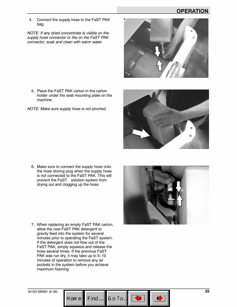
4. Connect the supply hose to the FaST PAKbag.
NOTE: If any dried concentrate is visible on thesupply hose connector or the on the FaST PAKconnector, soak and clean with warm water.
5. Place the FaST PAK carton in the cartonholder under the seat mounting plate on themachine.
NOTE: Make sure supply hose is not pinched.
6. Make sure to connect the supply hose ontothe hose storing plug when the supply hoseis not connected to the FaST PAK. This willprevent the FaST solution system fromdrying out and clogging up the hose.
7. When replacing an empty FaST PAK carton,allow the new FaST PAK detergent togravity feed into the system for severalminutes prior to operating the FaST system.If the detergent does not flow out of theFaST PAK, simply squeeze and release thehose several times. If the previous FaSTPAK was run dry, it may take up to 5--10minutes of operation to remove any airpockets in the system before you achievemaximum foaming.

OPERATION
8410D MM391 (9--97)36
STARTING THE MACHINE
8. You must be in the operator’s seat with thedirectional pedal in neutral, and your foot onthe brake pedal or with the parking brakeset.
FOR SAFETY: When starting machine,keep foot on brake and directional pedalin neutral.
9. Move the throttle lever to the idle position.
10.Turn the ignition switch key all the waycounter-clockwise and hold it there for 5 to15 seconds depending on the weather.
11.Turn the ignition switch key clockwise untilthe engine starts.
NOTE: Do not operate the starter motor for morethan 10 seconds at a time or after the engine hasstarted. Allow the starter to cool between startingattempt or damage to the starter motor mayoccur.
OPERATION
378410D MM391 (9--97)
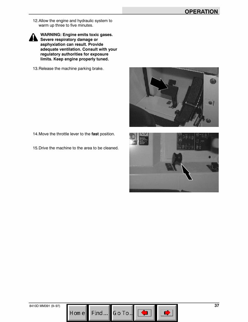
12.Allow the engine and hydraulic system towarm up three to five minutes.
WARNING: Engine emits toxic gases.Severe respiratory damage orasphyxiation can result. Provideadequate ventilation. Consult with yourregulatory authorities for exposurelimits. Keep engine properly tuned.
13.Release the machine parking brake.
14.Move the throttle lever to the fast position.
15.Drive the machine to the area to be cleaned.

OPERATION
8410D MM391 (3--03)38
SWEEPING, SCRUBBING, AND BRUSHINFORMATION
Pick up oversized debris before sweeping. Flattenor remove bulky cartons from aisles beforesweeping. Pick up pieces of wire, twine, string,etc., which could become entangled in brush orbrush plugs.
Plan the sweeping and scrubbing in advance. Tryto arrange long runs with minimum stopping andstarting. Sweep debris from very narrow aislesinto main aisles ahead of time. Do an entire flooror section at one time. Drive as straight a path aspossible. Avoid bumping into posts or scraping thesides of the machine. Overlap the brush paths.
Avoid turning the steering wheel too sharply whenthe machine is in motion. The machine is veryresponsive to the movement of the steeringwheel. Avoid sudden turns, except inemergencies.
Adjust the machine speed, scrub brush pressure,and detergent and solution flow as required whenscrubbing. Use minimum scrub brush pressureand solution flow required for the best scrubbingresults. The machine has an edge clean featurefor scrubbing against an edge.
When the recovery tank is almost full, therecovery tank full indicator will blink for almost aminute before the scrubbing system shuts off. Therecovery tank will have to be drained and cleaned.Then refill the solution tank with clean water anddetergent and continue cleaning.
For best results, use the correct brush type foryour sweeping and scrubbing application. Thefollowing are recommendations for mainsweeping, scrubbing, and side brush applications.
Nylon 5-double and 8-double row main sweepbrush -- Recommended for general sweeping,and has good hopper loading. Nylon has thelongest life of the bristle types. Use this brush forsweeping rough or irregular surfaces.
Nylon 24-row main sweep brush --Recommended for severe dust conditions onrough surfaces. This brush has excellent pickupand long life.
Polypropylene 8-double row main sweepbrush -- Superior pick-up of sand, gravel, andpaper litter. Polypropylene retains its stiffnesswhen wet, and can be used indoors or out withequal performance. Not recommended forhigh-temperature debris.
08002

OPERATION
398410D MM391 (3--03)
Polypropylene and Wire 8-double row mainbrush -- The wire bristles loosen slightly packedsoilage and heavier debris. The polypropylenebristles sweep up the debris with excellent hopperloading.
Fiber and Wire 24-row main sweep brush --Offers good sweeping action and pickup in heavydust concentrations. This brush is recommendedwhere soilage is slightly encrusted. The brush isnot recommended for heavy buildup or hardpacked soilage.
Wire 8-double row main sweep brush -- Thestiff wire bristles cut through compacted grime,hard to sweep dirt, and dirt mixed with oil, grease,or mud. This brush is recommended for foundrysweeping where heat may melt synthetic bristles.This brush has good hopper loading ability, but isnot recommended for dusty applications.
Polypropylene side brush -- A good generalpurpose brush for sweeping of light to mediumdebris in both indoor and outdoor applications.This brush is recommended when bristles mayget wet.
Nylon side brush -- A longer life, generalpurpose brush that is recommended for roughsurfaces.
Flat wire side brush -- Recommended foroutside and curb-side sweeping where soilage isheavy or compacted. The stiff wire bristles dig outsoilage. This brush is also recommended forfoundry sweeping where heat may melt syntheticbristles.
Polypropylene scrub brush -- Ageneral-purpose brush with stiff bristles foraggressive action on slightly compacted soilage.Works well on concrete, wood, and tile surfaces.
Wire scrub brush -- This brush is the mostaggressive. Recommended for soilage, heavybuildup and stripping rubber burns.
Non-scuff polypropylene scrub brush -- Thisbrush uses a softer, general purpose poly bristleto lift lightly compacted soilage, without scuffinghigh-gloss coated floors.
Nylon scrub brush -- Recommended forscrubbing coated floors. Cleans without scuffing.
08046

OPERATION
8410D MM391 (3--03)40
Super abrasive bristle scrub brush -- Nylonfiber impregnated with abrasive grit to removestains and soilage. Strong action on any surface,performing well on buildup, grease, or rubberburns.
Bassine scrub brush -- Traditional natural fiber isstill preferred by many for general scrubbing onquarry tile, terrazzo, and marble.
Stripping pad -- This pad is for stripping floors.Quickly and easily cuts through old finish toprepare the floor for recoating.
Scrubbing pad -- This pad is for scrubbing floors.Removes dirt, spills and scuffs, leaving a cleansurface ready for recoating.
Buffing pad -- This pad is for buffing floors.Quickly cleans and removes scuff marks whilepolishing the floor to a high gloss.
Polishing pad -- This pad is for polishing floors.Maintains a high gloss. Use to buff very softfinishes and lower traffic areas, or use forpolishing soft waxes on wood floors.
SWEEPING
1. Start the engine.
2. Move the throttle lever to the fast position.

OPERATION
418410D MM391 (9--97)
3. Press the main sweep brush speed 1 switchfor normal sweeping, or main sweep brushspeed 2 switch for sweeping light litter.
The side brush will automatically lower andstart if the side brush switch is on, thesweeping vacuum will start, the hopper doorwill open.
4. Sweep as needed.
STOP SWEEPING
1. Press the main sweep brush speed 1 switch,or main sweep brush speed 2 switch to stopthe sweeping operations.
The main brush will stop and raise, the sidebrush will stop and raise, the sweepingvacuum will stop, the hopper door will close,the filter shaker will operate for a short time,and the engine speed will remain at (Fast).
09561
09564

OPERATION
8410D MM391 (3--03)42
EMPTYING THE HOPPER
1. Slowly drive the machine to the debris siteor debris container.
2. Make sure the indicator light above thehopper door switch is on to show the hopperdoor is closed. If not, press the hopper doorswitch.
3. Press the filter shaker switch to shake thehopper dust filter.
4. Press and hold the hopper raise switch toraise the hopper to the desired height.
FOR SAFETY: When using machine,make sure adequate clearance isavailable before raising hopper.
NOTE: Be aware that the minimum ceiling heightneeded to high dump the hopper is 2490 mm(98 in).
FOR SAFETY: When using machine,move machine with care when hopper israised.
09568
09567
09569

OPERATION
438410D MM391 (3--03)
5. Drive the machine up to the debriscontainer.
6. Push the hopper door switch to open thehopper door. The indicator light above theswitch goes out.
7. Slowly back the machine away from thedebris site or debris container.
FOR SAFETY: When using machine, usecare when reversing machine.
8. Push the hopper door switch to close thehopper door. The indicator light above theswitch comes on.
9. Press and hold the hopper down switch tolower the hopper.
09570
09570
09571

OPERATION
8410D MM391 (6--05)44
FILLING THE TANKS
1. Start the engine.
2. Drive the machine to the filling site.
3. Shut the engine off.
4. Set the parking brake.
5. CONVENTIONAL SCRUBBING: Open thetank cover. Start filling the solution tank withwater. Pour the required amount ofdetergent into the solution tank. Fill thesolution tank to 75 mm (3 in) below the tankopening.
NOTE: Floor conditions, water condition, amountof soilage, type of soilage, and brush action allplay an important role in determining the type andconcentration of detergent used. For specificrecommendations, contact your Tennantrepresentative.
WARNING: Flammable materials cancause an explosion or fire. Do not useflammable materials in tank(s).
FOR SAFETY: Follow mixing andhandling instructions on chemicalcontainers.

OPERATION
458410D MM391 (6--05)
6. FaST SCRUBBING: Open the solution tankcovers and fill the solution tanks to 75 mm (3in) below the tank openings with cool clearwater only. Do not add cleaning detergents.
NOTE: When cleaning using FaST, USECLEAR COOL WATER ONLY. DO NOT addcleaning agents in solution tank.Conventional cleaning agents/restorers maycause failure to the FaST solution system.
ES mode: Lift up the operator seat.Remove the detergent tank lid and pour therequired amount of detergent into the tank.Put the lid back on the detergent tank andlower the operator seat.
WARNING: Flammable materials cancause an explosion or fire. Do not useflammable materials in tank(s).
NOTE: Floor conditions, water condition, amountof soilage, type of soilage, brush action all play animportant role in determining the type andconcentration of detergent used. For specificrecommendations, contact your TENNANTrepresentative.
ES mode with auto-fill: Connect the hosefrom the water source to the auto-fillconnection on the machine. Turn the ignitionkey to the on position and turn on the watersource. The auto-fill will automatically fill thetanks to the proper level for ES operationand automatically shut-off.
ES mode without auto-fill: The ES tankscan also be filled manually by filling thesolution tank to 75 mm (3 in) below tankopening, and filling recovery tank half full.
NOTE: If you do not want to use the ES system,do not put any water in the recovery tank. Turn offthe ES switch.
7. Close the tank cover.

OPERATION
8410D MM391 (6--05)46
SCRUBBING
1. Start the engine.
FOR SAFETY: When starting machine,keep foot on brake and directional pedalin neutral.
2. Move the throttle lever to the fast position.
3. Drive the machine to the area to be cleaned.

OPERATION
478410D MM391 (6--05)
4. FaST SCRUBBING: Press the FaSTswitch to the FaST system on position andpress the FaST solution flow switch to thedesired solution flow. See the SOLUTIONFLOW SWITCH (FaST) section of themanual.
NOTE: Leave the FaST switch in theCONVENTIONAL SCRUBBING position if notusing the FaST system.
5. CONVENTIONAL SCRUBBING: Adjust thesolution flow to the floor as needed. See theSOLUTION SWITCH (WITHOUT FaST)section of the manual.

OPERATION
8410D MM391 (6--05)48
6. Press the scrub switch to start the scrubbingoperation.
As long as the machine is not in reverse, thescrub head will lower and the scrub brusheswill start. The rear squeegee willautomatically lower and the scrubbingvacuum will start. The solution flow will start,if the solution flow switch is on. Also theoptional ES system and detergent pump willstart, if the switches are on.
WARNING: Flammable materials orreactive metals can cause explosion orfire. Do not pick up.
NOTE: If you do not want to use the ES system,press the ES switch so the indicator above theswitch is off. Press and hold the detergent switchuntil both indicator lights are off. Turn off thedetergent only if detergent has been added to thesolution tank.
7. Adjust brush pressure for cleaningapplication.
The brush pressure has three positions.Under normal conditions, the brush pressureshould be set in the minimum setting. Underheavy grime conditions, the brush pressureshould be set in the maximum setting.
8. Drive the machine forward and scrub asrequired.
11110
11111
11112
11110

OPERATION
498410D MM391 (6--05)
DOUBLE SCRUBBING
Double scrubbing is a method for removing heavyfloor accumulations. This is done by making twopasses over the area to be cleaned with themachine.
Double scrubbing can be performed using theFaST SCRUBBING SYSTEM orCONVENTIONAL SCRUBBING methods.
First, make a pass over the area scrubbing withthe squeegee up. This dispenses solution over thearea allowing the solution to soak on the floor.Use the maximum solution and detergent flowsettings. Use a higher brush pressure setting. Letthe solution remain on the floor for 5 to15 minutes. Then make a second pass scrubbingwith the squeegee down.
FOR SAFETY: When using machine, goslow on inclines and slippery surfaces.
STOP SCRUBBING
1. Press the scrub switch to stop the scrubbingoperations.
The scrub brushes will stop and the scrubhead will raise. The ES detergent pump willstop, and the solution flow will stop, theFaST system will stop. After a short delay,the rear squeegee will automatically raiseand the scrubbing vacuum fan will stop. Theengine speed will remain at (Fast).
Drive the machine forward until the vacuumfan shuts off.
11110

OPERATION
8410D MM391 (6--05)50
DRAINING AND CLEANING THE TANKS
When you are finished scrubbing or you hear thevacuum fan shut off and the machine startstrailing water, the recovery tank should be drainedand cleaned. The solution tank then can be filledagain for additional scrubbing.
If you used the machine in ES mode, the solutiontank should also be drained and cleaned whenyou are finished scrubbing.
1. Stop scrubbing.
2. Drive the machine next to an appropriatedisposal site.
3. Shut the engine off.
4. Set the parking brake.

OPERATION
518410D MM391 (6--05)
5. Unscrew the drain hose cap from the accesscap of the recovery tank drain.
6. Pull out and place the drain hoses next tothe floor drain. Remove the drain end capfrom the hose. Stand back, the solutionrushes out of the drain hoses.
NOTE: To prevent the solution from rushing outof the recovery tank drain hose, leave the engineon and lower the rear squeegee to start up thevacuum fan, before removing the drain hose endcap. Once the drain hose is placed next to thefloor drain, raise the squeegee and shut off theengine. Be sure to set the machine parking brake.
7. Open the tank cover.
8. Spray the inside of the recovery tank withclean water.
9. Remove the large drain cap and flush outthe bottom on the recovery tank.
10. ES mode: Clean the ES filter. If the filtercan’t be rinsed off through the recovery tankfill opening, the filter can be removed fromthe recovery tank by disconnecting the ESpump wire and solution hose, andunscrewing the ES pump cap from therecovery tank.

OPERATION
8410D MM391 (6--05)52
11. ES mode: Drain the solution tank. Flush outthe solution tank with clean water. Rinse thesolution outlet filters at the bottom of thetank through the drain access.
12. Lower the tank cover.
13. Replace the drain hoses and drain caps.
STOP THE MACHINE
1. Stop sweeping and scrubbing.
2. Take your foot off the directional pedal. Stepon the brake pedal.
3. Move the throttle lever to the idle position.
07754

OPERATION
538410D MM391 (12--03)
4. Set the machine parking brake.
5. Turn the ignition switch keycounter-clockwise to stop the engine.Remove the switch key.
FOR SAFETY: Before leaving orservicing machine; stop on levelsurface, set parking brake, turn offmachine and remove key.

OPERATION
8410D MM391 (6--05)54
POST-OPERATION CHECKLIST
- Check the brushes adjustment. See TOCHECK AND ADJUST MAIN BRUSHPATTERN and SIDE BRUSH inMAINTENANCE.
- Check for wire, string, or twine wrappedaround the sweeping and scrub brushes.
- Check the brush skirts for damage, wear,and adjustments.
- Check the squeegees for wear or damage.
- Drain and clean the recovery tank.
- ES mode: Drain and clean the solution tankand clean the solution outlet filter. Clean theES filter.
- Check the vacuum hoses for debris orobstructions.
- Check for fuel odor that indicates a fuel leak.
- Check under the machine for leak spots(fuel, oil, coolant, scrubbing solution).
- Empty hopper and clean dust filter.
- Check the service records to determinemaintenance requirements.
- FaST Scrubbing: If FaST PAK is empty afterscrubbing, install a new FaST PAK orconnect supply hose to the storage plug.

OPERATION
558410D MM391 (3--03)
ENGAGING HOPPER SUPPORT BAR
1. Set the machine parking brake.
FOR SAFETY: When starting machine,keep foot on brake and directional pedalin neutral.
2. Start the engine.
3. Raise the hopper all the way up.
4. Lift and position the hopper support barunder the hopper lift arm.
WARNING: Raised hopper may fall.Engage hopper support bar.
09569
08003

OPERATION
8410D MM391 (3--03)56
5. Slowly lower the hopper so the lift arm restson the support bar.
WARNING: Lift arm pinch point. Stayclear of hopper lift arms.
6. Shut the engine off.
DISENGAGING HOPPER SUPPORT BAR
1. Start the engine.
FOR SAFETY: When starting machine,keep foot on brake and directional pedalin neutral.
2. Raise the hopper slightly to release thehopper support bar.
07803
09569

OPERATION
578410D MM391 (3--03)
3. Put the support bar in its storage position.
WARNING: Lift arm pinch point. Stayclear of hopper lift arms.
4. Lower the hopper.
5. Shut the engine off.
OPERATION ON INCLINES
Drive the machine slowly on inclines. Use thebrake pedal to control machine speed ondescending inclines.
The maximum rated incline for sweeping andscrubbing with the machine is 6_. The maximumrated incline during transport of the machine is 8_.
FOR SAFETY: When using machine, goslow on inclines and slippery surfaces.
08004
09571

OPERATION
8410D MM391 (3--03)58
OPTIONS
VACUUM WAND (WET)
The vacuum wand uses the machine’s vacuumsystem. The vacuum hose allows pick-up of spillsthat are out of reach of the machine.
1. Stop the machine within reach of the area tobe vacuumed.
2. Lower the squeegee and shut the engine off.
3. Set the machine parking brake.
FOR SAFETY: Before leaving orservicing machine; stop on levelsurface, set parking brake, turn offmachine and remove key.
11114

OPERATION
598410D MM391 (3--03)
4. Remove the squeegee suction hose fromthe rear squeegee and connect the vacuumhose.
5. Put together the wand and the wand hose.
6. Start the engine.
7. Move the throttle lever to the fast position.
8. Lower the squeegee to turn the vacuumsystem on.
11114

OPERATION
8410D MM391 (3--03)60
9. Vacuum the floor.
10. Shut the engine off.
11. Remove the vacuum hose from thesqueegee suction hose and connect thesqueegee suction hose to the rearsqueegee.
12. Put the vacuum wand and hose in themounting clips.

OPERATION
618410D MM391 (6--05)
MACHINE TROUBLESHOOTING
Problem Cause Remedy
Excessive dusting Brush skirts and dust seals worn,damaged, out of adjustment
Replace or adjust brush skirts ordust seals
Hopper dust filter clogged Shake and/or clean or replacedust filter
Vacuum hose damaged Replace vacuum hose
Vacuum fan failure Contact TENNANT servicepersonnel
Thermo Sentry tripped Reset Thermo Sentry
Poor sweeping performance Brush bristles worn Replace brushes
Main and side brushes notadjusted properly
Adjust main and side brushes
Debris caught in main brush drivemechanism
Free drive mechanism of debris
Main brush drive failure Contact TENNANT servicepersonnel
Side brush drive failure Contact TENNANT servicepersonnel
Hopper full Empty hopper
Hopper lip skirts worn or damaged Replace lip skirts
Wrong sweeping brush Contact TENNANT representativefor recommendations
Problem Cause Remedy
FaST System does not operate FaST switch is set forConventional scrubbing
Set the FaST switch for FaSTsystem scrubbing
FaST circuit breaker tripped Determine cause and reset the10A circuit breaker button
Clogged FaST PAK supply hoseand/or connector
Soak connector and hose in warmwater and clean
FaST PAK carton is empty or notconnected
Replace FaST PAK carton and/orconnect supply hose
FaST system is not primed To prime, operate the FaST solu-tion system for 5 to 10 minutes.
Clogged flow control orifice/screen Remove and clean orifice/screen
Faulty pump or air compressor Contact TENNANT representative
Clogged filter screen Drain solution tank, remove andclean filter screen
Faulty detergent timer module Contact Tennant representative
FaST solution flow switch is off Turn FaST solution flow switch on

OPERATION
8410D MM391 (6--05)62
Problem Cause Remedy
Trailing water -- poor or nowater pickup.
Worn rear squeegee blades. Rotate or replace squeegeeblades.
Rear squeegee out of adjustment. Adjust rear squeegee.
Side squeegees raised. Lower side squeegees.
Worn side squeegee blades. Replace side squeegee blades.
Side squeegees out ofadjustment.
Adjust side squeegees.
Tank cover not seated. Reseat tank cover.
Tank cover seals worn. Replace seals.
Too much solution flow to floor. Reduce solution flow to floor.
Vacuum hose clogged. Flush vacuum hoses.
Recovery tank full. Drain recovery tank.
Check ES pump and filter
Float stuck shutting off vacuum. Clean float.
Debris caught on rear squeegee. Remove debris.
Foam filling recovery tank. Empty recovery tank; use less orchange detergent.
Vacuum hose to rear squeegeedisconnected or damaged.
Reconnect or replace vacuumhose.
Vacuum fan to recovery tank hosedamaged.
Replace hose.
Little or no solution flow to thefl
Solution tank empty. Fill solution tank.floor. Solution flow switch turned off. Turn solution flow switch on.
Solution supply lines plugged. Flush solution supply lines.
ES switch off. Turn ES switch on.
Poor scrubbing performance. Debris caught on scrub brushes. Remove debris.
Improper detergent or brushesused.
Check with TENNANTrepresentative for advice.
Worn scrub brushes. Replace scrub brushes.
ES system does not fill solutiont k
Clogged solution pump or lines. Flush ES system.tank. ES float stuck. Clean floats of debris.
Clogged ES pump filter. Clean filter.
Water levels too low in tanks. Add water.

OPERATION
638410D MM391 (6--05)

MAINTENANCE
8410D MM391 (5--07)64
MAINTENANCE
1
2 3 4 5 6 7
8 10111213141516
8
9
4 7
17
18
18
19
09076
MAINTENANCE CHART
NOTE: Check procedures indicted (H) after the first 50-hours of operation.
Interval Key Description ProcedureLubricant/
Fluid
No. ofServicePoints
Daily 2 Engine air filter Check indicator -- 1Daily 2 Engine air filterEmpty dust cap -- 1
2 Engine crankcase Check oil level EO 12 Engine crankcaseCheck coolant level in resservoir WG 1
11 Brush compartment skirts Check for damage, wear and ad-justment
-- 5
9 Hopper lip skirts Check for damage, wear and ad-justment
-- 3
11 Main sweep brush Check for damage, wear, and ad-justment
-- 1
Check brush pattern -- 110 Side brush Check for damage, wear, and ad-
justment-- 1
Check brush pattern -- 19 Hopper dust filter Shake -- 216 Rear Squeegee Check for damage and wear -- 116 Rear Squeegee
Check deflection -- 14 Side Squeegees Check for damage and wear -- 24 Scrub brushes Check for damage and wear -- 15 Recovery tank Clean -- 112 Recovery tank, ES mode Clean ES filter -- 16 Solution tank, ES mode Clean -- 119 FaST PAK supply hose and
connectorClean and connect hose to stor-ing plug when not in use
-- 1

MAINTENANCE
658410D MM391 (6--05)
Interval Key Description ProcedureLubricant/
Fluid
No. ofServicePoints
50 Hours 11 Main sweep brush Rotate end-for-end -- 150 Hours2 Fuel pipes and clamps Check for tightness and wear -- 12 Engine crankcase Change oil and filter EO 118 Rear squeegee casters Lubricate SPL 219 FaST fiilter screen Clean -- 1
100 Hours 1 Radiator Clean core exterior -- 1Check coolant level WG 1
2 Engine belt Check tension -- 19 Hopper dust filter Check for damage, clean or re-
place-- 1
3 Hydraulic fluid reservoir Check fluid level HYDO 18 Tires Check for damage -- 311 Main sweep brush and
hopper sealsCheck for damage or wear -- 8
16 Rear squeegee Check leveling -- 1200 Hours 1 Radiator hoses and clamps Check for tightness and wear -- 2
14 Parking brake Check adjustment -- 114 Brake pedal Check and adjust travel -- 117 Rear wheel support bear-
ingsLubricate SPL 2
10 Side brush guard Rotate 90_ -- 17 Lift arm pivots Lubricate SPL 49 Hopper door pivots Lubricate SPL 219 FaST Air filter Clean -- 1
400 Hours 8 Front wheel bearings Check, lubricate, and adjust SPL 22 Fuel filter Replace cartridge -- 115 Fuel tank Remove sediment -- 11 Cooling system Flush WG 1
800 Hours 3 Hydraulic reservoir Replace filler cap -- 1yReplace suction strainer -- 1Change hydraulic fluid HYDO 1
3 Hydraulic fluid filter Change filter element -- 1-- Hydraulic hoses Check for wear and damage -- All17 Propelling motor HTorque shaft nut -- 117 Rear wheel HTorque wheel nuts -- 113 Battery HClean and tighten battery cable
connections-- 1
Check electrolyte DW 1
LUBRICANT/FLUIDEO Engine oil, SAE--CC/CD rated. . . .HYDO Tennant Company or approved hydraulic fluid.WG Water and permanent-type ethylene glycol anti-freeze, --34_ C (--30_ F). . .SPL Special lubricant, Lubriplate EMB grease (Tennant part number 01433--1). . .DW Distilled water. . . .
NOTE: More frequent intervals may be required in extremely dusty conditions.

MAINTENANCE
8410D MM391 (12--04)66
LUBRICATION
ENGINE
Check the engine oil level daily. Change theengine oil and oil filter every 50 hours of machineoperation. Use 10W30 SAE--CC/CD/CE ratedengine oil.
Fill the engine with oil to the level indicated on theoil dipstick. Low oil level is indicated by the markclosest to the end of the dipstick. Full level isindicated by the mark closest to the top of thedipstick. The engine oil capacity is 6.15 L (6.5 qt)without the oil filter.
The engine oil filter is mounted on the right side ofthe machine frame above the scrub brushes.
REAR WHEEL SUPPORT
The rear wheel support pivots the rear wheel. Thesupport has two grease fittings for the bearings.The rear wheel support bearings must belubricated every 200 hours of operation. UseLubriplate EMB grease (Tennant part number01433--1).
08005

MAINTENANCE
678410D MM391 (3--03)
FRONT WHEEL BEARINGS
Inspect the front wheel bearings for seal damage,and repack and adjust every 400 hours ofoperation. Use Lubriplate EMB grease (Tennantpart number 01433--1).
HOPPER LIFT ARM PIVOTS
The hopper lift arms have four grease fittings, twoon each lift arm. One fitting is at the top pivot ofthe lift arm, and the other is at the middle pivot.
The lift arms should be lubricated with LubriplateEMB grease (Tennant part number 01433--1)every 200 hours of operation.
HOPPER DOOR PIVOTS
The hopper door pivot has two grease fittings, oneon each side of the hopper. The hopper doorshould be lubricated with Lubriplate EMB grease(Tennant part number 01433--1) every 200 hoursof operation.
REAR SQUEEGEE CASTERS (for machinesbelow serial number 012215)
Each of the rear casters has a grease fitting. Thecasters must be lubricated every 50 hours ofoperation. Use Lubriplate EMB grease (Tennantpart number 01433--1).
08006

MAINTENANCE
8410D MM391 (3--03)68
HYDRAULICS
HYDRAULIC FLUID RESERVOIR
The reservoir is located in the enginecompartment next to the radiator.
Mounted on top of the reservoir is a filler cap witha built-in breather and fluid level dipstick. Replacethe cap every 800 hours of operation.
Check the hydraulic fluid level at operatingtemperature every 100 hours of operation. Makesure the hopper is down when checking hydraulicfluid level. The end of the dipstick is marked withFULL and ADD levels to indicate the level ofhydraulic fluid in the reservoir.
Lubricate the filler cap gasket with a film ofhydraulic fluid before putting the cap back on thereservoir.
ATTENTION! Do not overfill thehydraulic fluid reservoir or operate themachine with a low level of hydraulicfluid in the reservoir. Damage to themachine hydraulic system may result.
Drain and refill the hydraulic fluid reservoir withnew hydraulic fluid every 800 hours of operation.
The hydraulic fluid filter is located at the bottom ofthe engine compartment. Replace the filterelement every 800 hours of operation.
The reservoir has a built-in strainer outlet thatfilters hydraulic fluid before it enters the system.Replace the strainer every 800 hours of operation.
HYDRAULIC FLUID
The quality and condition of the hydraulic fluidplay a very important role in how well the machineoperates. Tennant’s hydraulic fluid is speciallyselected to meet the needs of Tennant machines.

MAINTENANCE
698410D MM391 (3--03)
Tennant’s hydraulic fluids provide a longer life forthe hydraulic components. There are two fluidsavailable for different temperature ranges:
Tennant part no. Ambient Temperature
65869 above 7_ C (45_ F)
65870 below 7_ C (45_ F)
The higher temperature fluid has a higherviscosity and should not be used at the lowertemperatures. Damage to the hydraulic pumpsmay occur because of improper lubrication.
The lower temperature fluid is a thinner fluid forcolder temperatures.
If a locally-available hydraulic fluid is used, makesure the specifications match Tennant hydraulicfluid specifications. Using substitute fluids cancause premature failure of hydraulic components.
ATTENTION! Hydraulic componentsdepend on system hydraulic fluid forinternal lubrication. Malfunctions,accelerated wear, and damage will resultif dirt or other contaminants enter thehydraulic system.
HYDRAULIC HOSES
Check the hydraulic hoses every 800 hours ofoperation for wear or damage.
Fluid escaping at high pressure from a very smallhole can be almost invisible, and can causeserious injuries.
See a doctor at once if injury results fromescaping hydraulic fluid. Serious infection orreaction can develop if proper medical treatmentis not given immediately.
FOR SAFETY: When servicing machine,use cardboard to locate leakinghydraulic fluid under pressure.
If you discover a fluid leak, contact your mechanicor supervisor.
PROPELLING MOTOR
Torque the shaft nut to 508 Nm (375 ft lb)lubricated, 644 Nm (475 ft lb) dry after the first50-hours of operation, and every 800 hours thereafter.
00002

MAINTENANCE
8410D MM391 (5--07)70
ENGINE
COOLING SYSTEM
Check the coolant level in the reservoir daily.Check the radiator coolant level every 100 hoursof operation. Use clean water mixed with apermanent-type, ethylene glycol antifreeze to a--34_ C (--30_ F) rating.
FOR SAFETY: When servicing machine,avoid contact with hot engine coolant.
Check the radiator hoses and clamps every200 hours of operation. Tighten the clamps if theyare loose. Replace the hoses and clamps if thehoses are cracked, harden, or swollen.
Check the radiator core exterior and hydrauliccooler fins for debris every 100 hours ofoperation. Open the radiator grille for cleaningaccess. Blow or rinse all dust, which may havecollected on the radiator, in through the grille andradiator fins, opposite the direction of normal airflow. Be careful not to bend the cooling fins whencleaning. Clean thoroughly to prevent the finsbecoming encrusted with dust. Clean the radiatorand cooler only after the radiator has cooled toavoid cracking.
FOR SAFETY: When servicing machine,wear eye and ear protection when usingpressurized air or water.
Flush the radiator and the cooling system every800 hours of operation, using a dependablecleaning compound.

MAINTENANCE
718410D MM391 (3--03)
AIR FILTER INDICATOR
The air filter indicator shows when to replace theair filter element. Check the indicator daily. Theindicator’s red line will move as the air filterelement fills with dirt. Do not replace the air filterelement until the red line reaches5 kPa (20 in H2O) and the “SERVICE WHENRED” window is filled with red. The indicator’s redline may return to a lower reading on the scalewhen the engine shuts off. The red line will returnto a correct reading after the engine runs for awhile.
Reset the air filter indicator by pushing the resetbutton on the end of the indicator after replacingthe air filter element.
AIR FILTER
The engine air filter housing has a dust cap and adry cartridge-type air filter element. Empty thedust cap daily. The air filter must be replacedwhenever the filter element is damaged or whenthe air filter indicator shows a restriction. The airfilters cannot be cleaned.
Machines with the heavy duty air filter option havea safety element. It is inside the standardelement. Replace this element after the regularelement becomes damaged or changed threetimes.
Install the dust cap on the air filter housing withthe arrows pointing up.
Replace the air filter element only when the airfilter indicator shows restriction in the air intakesystem. Do not remove the air filter element fromthe housing unless it is restricting air flow.
02492

MAINTENANCE
8410D MM391 (6--96)72
FUEL FILTER
The fuel filter cartridge filters impurities from thefuel. The filter is located by the fuel tank.
Replace the fuel filter element every 400 hours ofoperation.
FUEL LINES
Check the fuel lines every 50 hours of operation.If the clamp band is loose, apply oil to the screwof the band, and securely tighten the band.
Made of rubber, the fuel lines become worn outwhether the engine has been used much or not.Replace the fuel lines and clamp bands every twoyears.
If the fuel lines and clamp bands are found wornor damaged before two years’ time, replace orrepair them at once. Bleed the fuel system afterreplacement of any of the fuel lines, seePRIMING THE FUEL SYSTEM. When the fuellines are not installed, plug both ends with cleancloth or paper to prevent dirt from entering thelines. Dirt in the lines can cause fuel injectionpump malfunction.
PRIMING THE FUEL SYSTEM
Priming the fuel system removes pockets of air inthe fuel lines and fuel components. Air in the fuelsystem will prevent smooth engine operation.
Prime the fuel system after running out of fuel,changing fuel filter elements or repairing a fuelsystem component.
1. Stop the engine and set the machine parkingbrake.
FOR SAFETY: Before leaving orservicing machine; stop on levelsurface, set parking brake, and turn offmachine.
2. Fill the fuel tank.
3. Open the side and top engine access doors.
FOR SAFETY: When servicing machine,allow engine to cool. Keep flames andsparks away from fuel system servicearea. Keep area well ventilated.
4. Open the air vent on top of the fuel injectionpump.

MAINTENANCE
738410D MM391 (6--96)
5. Start the engine, operate it for one minute,then stop it; or operate the starter motor inten-second intervals until a steady stream offuel flows from the vent.
6. Close the air vent.
7. Close the access doors.
BATTERY
The battery for the machine is a low maintenancebattery. Do not add water to the battery, orremove the battery vent plugs.
The battery is located at the bottom of theoperator compartment.
After the first 50 hours of operation, and every800 hours after that, clean and tighten the batteryconnections.
FOR SAFETY: When servicing machine,avoid contact with battery acid.

MAINTENANCE
8410D MM391 (6--96)74
BELTS AND CHAINS
ENGINE BELT
The engine belt is driven by the engine crankshaftpulley and drives the engine water pump andalternator pulleys. Proper belt tension is obtainedwhen the belt deflects 7 to 9 mm (0.28 to 0.35 in)from a force of 10 kg (22 lb) applied at themid-point of the longest span.
Check and adjust the belt tension every 100 hoursof operation.
WARNING: Moving belt and fan. Keepaway.
STATIC DRAG CHAIN
A static drag chain prevents the buildup of staticelectricity in the machine. The chain is attached tothe machine by a rear main brush skirt retainingbolt.
Make sure the chain is touching the floor at alltimes.
08935
08009

MAINTENANCE
758410D MM391 (3--03)
DEBRIS HOPPER
HOPPER DUST FILTER
The dust filter filters the air pulled up from thehopper. The dust filter is equipped with a shakerto remove the accumulated dust particles. Thedust filter shaker is operated by the filter shakerswitch.
Shake the dust filter before emptying the hopperand at the end of every work shift. Check andclean or replace the dust filter every 100 hours ofoperation.
To clean the dust filter, use one of the followingmethods:
D SHAKING -- Press the filter shaker switch.
D TAPPING -- Tap the filter gently on a flatsurface with the dirty side down. Do notdamage the edges of the filter element orthe filter will not seat properly in the filterframe.
D AIR -- Always wear eye protection whenusing compressed air. Blow air through thedust filter opposite the direction of thearrows. Never use more than 690 kPa(100 psi) of air pressure and never closerthan 50 mm (2 in) away from the filter.
FOR SAFETY: When servicing machine,wear eye and ear protection when usingpressurized air or water.
D WATER -- The dust filter can be rinsed withwater, but the filter will degrade with eachrinsing. Replaced the filter after rinsing fivetimes. Rinse with a low pressure gardenhose through the dust filter opposite thedirection of the arrows.
NOTE: Be sure the dust filter is dry beforereinstalling it in the machine.
REMOVING HOPPER DUST FILTER
8. Stop the engine and set the machine parkingbrake.
FOR SAFETY: Before leaving orservicing machine; stop on levelsurface, set parking brake, turn offmachine and remove key.
08010

MAINTENANCE
8410D MM391 (3--03)76
9. Open the hopper cover.
10.Disconnect the shaker motor wireconnectors.
11.Remove the four retaining nuts from the filtershaker frame.
12.Pull the filter shaker frame out of the hopper.
13.Lift the dust filter element out of the hopperinsert.
14.Clean or discard the dust filter as required.
15.Put the cleaned or new dust filter in thehopper insert with the arrows pointing up.
16.Put the shaker frame on top of the panelfilter.
17. Install the four retaining nuts and tighten.
18. Connect the shaker motor wire connectors.
08011
08014
08012
08013

MAINTENANCE
778410D MM391 (6--05)
THERMO SENTRY
The Thermo Sentry senses the temperature of theair pulled up from the hopper. If there is a fire inthe hopper, the Thermo Sentry stops the vacuumfan and cuts off the air flow.
Reset the Thermo Sentry by pushing in its resetbutton.
SCRUB HEAD
The scrub head encloses the scrub brushes and asolution dispensing system. The scrub head islocated directly behind the sweeping brushcompartment.
The scrub head is factory adjusted and themeasurement should not be changed unlessscrub head parts are damaged or are replaced.
BRUSHES
MAIN SWEEP BRUSH
The main sweep brush is cylindrical and spansthe width of the machine, sweeping debris into thehopper.
Check the brush daily for wear or damage.Remove any string or wire tangled on the mainbrush, main brush drive hub, or main brush idlerhub.
Check the main sweep brush pattern daily. Thepattern should be 50 to 65 mm (2.0 to 2.5 in) widewith the main sweep brush in the loweredposition. Adjust the main sweep brush pattern byturning the main brush pressure knob located nextto the brush position lever.
Rotate the main brush end-for-end every 50 hoursof operation for maximum brush life and bestsweeping performance.
Sweeping performance often becomes lesseffective as the bristle length is worn. Replace themain brush when the remaining bristles measurebetween 40 mm (1 1/2 in) and 50 mm (2 in) inlength.

MAINTENANCE
8410D MM391 (3--03)78
REPLACING MAIN SWEEP BRUSH
1. Stop the engine and set the machine parkingbrake.
FOR SAFETY: Before leaving orservicing machine; stop on levelsurface, set parking brake, turn offmachine and remove key.
2. Raise the main sweep brush.
3. Open the right side brush access door.
4. Unlatch and remove the brush idler plate.
5. Grasp the main sweep brush; pull it off thebrush drive plug and out of the main brushcompartment.
6. Put the new or rotated end-for-end mainsweep brush on the floor next to the accessdoor.
7. Slide the main sweep brush onto the driveplug. Rotate the brush until it engages thedrive plug, and push it all the way onto theplug.
8. Slide the brush idler plate plug onto the mainsweep brush.
9. Latch the idler plate onto the machine frame.
10. Close the right side brush access door.
08016
08017
08018
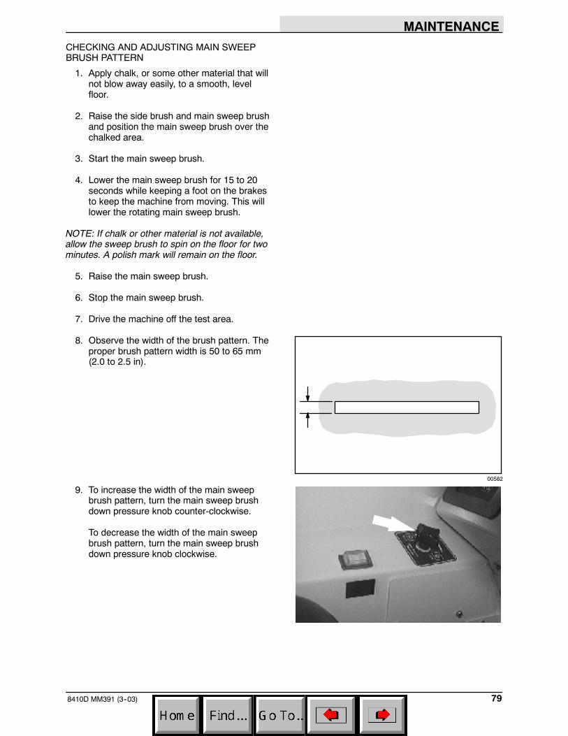
MAINTENANCE
798410D MM391 (3--03)
CHECKING AND ADJUSTING MAIN SWEEPBRUSH PATTERN
1. Apply chalk, or some other material that willnot blow away easily, to a smooth, levelfloor.
2. Raise the side brush and main sweep brushand position the main sweep brush over thechalked area.
3. Start the main sweep brush.
4. Lower the main sweep brush for 15 to 20seconds while keeping a foot on the brakesto keep the machine from moving. This willlower the rotating main sweep brush.
NOTE: If chalk or other material is not available,allow the sweep brush to spin on the floor for twominutes. A polish mark will remain on the floor.
5. Raise the main sweep brush.
6. Stop the main sweep brush.
7. Drive the machine off the test area.
8. Observe the width of the brush pattern. Theproper brush pattern width is 50 to 65 mm(2.0 to 2.5 in).
9. To increase the width of the main sweepbrush pattern, turn the main sweep brushdown pressure knob counter-clockwise.
To decrease the width of the main sweepbrush pattern, turn the main sweep brushdown pressure knob clockwise.
00582

MAINTENANCE
8410D MM391 (3--03)80
If the main sweep brush pattern is tapered,more than 15 mm (0.5 in) on one end thanthe other, adjust the taper with the taperadjustment bracket at the idler end of thebrush.
A. Loosen the bracket mounting bolts.
B. Turn the taper adjustment nutcounter-clockwise to increase thepattern width at the brush idler end, andclockwise to decrease the pattern widthat the brush idler end. Tighten themounting bolts.
C. Check the main sweep brush patternand readjust as necessary. Then adjustthe width of the main brush pattern.
00601
09183
09184
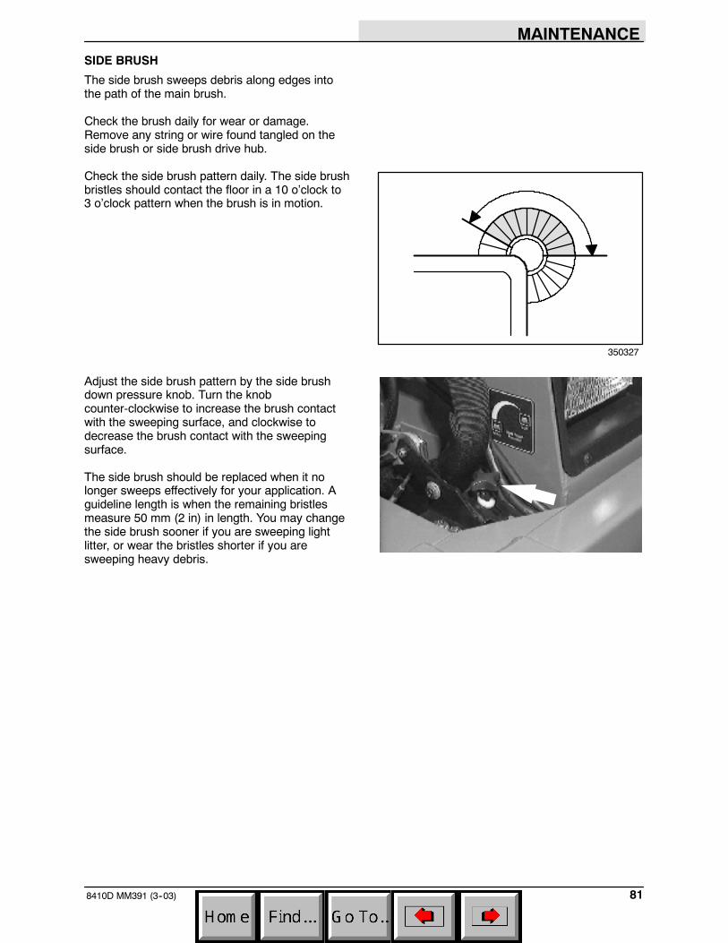
MAINTENANCE
818410D MM391 (3--03)
SIDE BRUSH
The side brush sweeps debris along edges intothe path of the main brush.
Check the brush daily for wear or damage.Remove any string or wire found tangled on theside brush or side brush drive hub.
Check the side brush pattern daily. The side brushbristles should contact the floor in a 10 o’clock to3 o’clock pattern when the brush is in motion.
Adjust the side brush pattern by the side brushdown pressure knob. Turn the knobcounter-clockwise to increase the brush contactwith the sweeping surface, and clockwise todecrease the brush contact with the sweepingsurface.
The side brush should be replaced when it nolonger sweeps effectively for your application. Aguideline length is when the remaining bristlesmeasure 50 mm (2 in) in length. You may changethe side brush sooner if you are sweeping lightlitter, or wear the bristles shorter if you aresweeping heavy debris.
350327

MAINTENANCE
8410D MM391 (3--03)82
REPLACING SIDE BRUSH
1. Empty the debris hopper.
2. Set the machine parking brake.
3. Stop the engine.
FOR SAFETY: Before leaving orservicing machine; stop on levelsurface, set parking brake, turn offmachine and remove key.
4. Remove the side brush retaining pin fromthe side brush drive shaft by pulling the pinkeeper off over the end of the pin.
5. Slide the side brush off the side brush driveshaft.
NOTE: Remove the drive hub and put it on thenew brush if one is not installed.
6. Slide the new side brush onto the side brushdrive shaft.
7. Insert the side brush retaining pin throughthe side brush hub and shaft.
8. Secure the pin by clipping the pin keeperover the end of the pin.
9. Disengage the hopper support bar and lowerthe hopper.
10. Adjust the side brush pattern with the sidebrush down pressure knob.
SIDE BRUSH GUARD
Rotate the side brush guard 90_ every 200 hoursof operation. Replace the brush guard after allfour sides have been used.
08019
08049

MAINTENANCE
838410D MM391 (3--03)
SCRUB BRUSHES
Three disc-type scrub brushes scrub the floor. Aspring lock clip holds the scrub brush onto thedrive hub.
The scrub brushes should be checked daily fortangled wire or string, wear, and damage. Thebrushes should be replaced if large portions of thebrush bristles are missing or if the remainingbrush bristle measure 0.25 in (6 mm) or less inlength.
NOTE: Be sure to replace the scrub brushes insets. Otherwise one scrub brush will be moreaggressive than the other.
REPLACING THE SCRUB BRUSHES
1. Set the machine parking brake.
2. Raise the scrub brushes.
3. Stop the engine.
FOR SAFETY: Before leaving orservicing machine; stop on levelsurface, set parking brake, turn offmachine and remove key.
4. Press the brush spring clip ends togetherwith your thumb and index finger to removethe scrub brush. Repeat for the otherbrushes.
5. Start with the center brush. Slide the newscrub brush under the scrub brush driveassembly.
6. Line up the scrub brush drive socket with thedrive plug.
7. Press the brush spring clip together and liftthe scrub brush onto the drive plug. Releasethe spring clip when the brush is in place.Repeat for the other brushes.

MAINTENANCE
8410D MM391 (6--05)84
SOLUTION SYSTEM
RECOVERY TANK
The recovery tank stores recovered solution. Therecovery tank should be drained and cleaneddaily, or when the recovery tank full light comeson.
ES option: The ES filter should be cleaned daily.The ES filter can be rinsed while in the recoverytank through the right tank fill opening, or byremoving the ES pump from the recovery tank.
SOLUTION TANK
The solution tank contains the cleaning solution.
The solution tank does not require regularmaintenance. If deposits form on the bottom ofthe tank, rinse the tank with a strong blast ofwarm water. The right tank can be flushed throughthe drain opening. Drain the tank with the solutiontank drain hose.
The solution tank on machines with the ES optionshould be drained and cleaned daily. Rinse thesolution outlet filters at the bottom of the tankthrough the drain access.
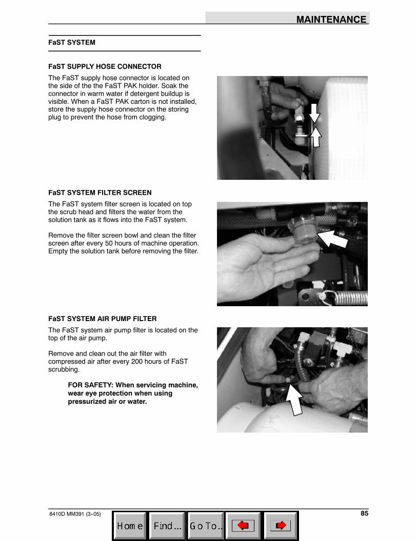
MAINTENANCE
858410D MM391 (3--05)
FaST SYSTEM
FaST SUPPLY HOSE CONNECTOR
The FaST supply hose connector is located onthe side of the the FaST PAK holder. Soak theconnector in warm water if detergent buildup isvisible. When a FaST PAK carton is not installed,store the supply hose connector on the storingplug to prevent the hose from clogging.
FaST SYSTEM FILTER SCREEN
The FaST system filter screen is located on topthe scrub head and filters the water from thesolution tank as it flows into the FaST system.
Remove the filter screen bowl and clean the filterscreen after every 50 hours of machine operation.Empty the solution tank before removing the filter.
FaST SYSTEM AIR PUMP FILTER
The FaST system air pump filter is located on thetop of the air pump.
Remove and clean out the air filter withcompressed air after every 200 hours of FaSTscrubbing.
FOR SAFETY: When servicing machine,wear eye protection when usingpressurized air or water.

MAINTENANCE
8410D MM391 (3--03)86
SQUEEGEES
The squeegee channels water into the vacuumfan suction. The front blade channels the water,and the rear blade wipes the floor.
There are two types of squeegee bladesavailable; one for smooth surfaces is standard onthe machine, and one for rough surfaces is anoption.
Check the squeegee blades for damage and weardaily. Rotate or replace either of the squeegeeblades if the leading edge is torn or worn half-waythrough the thickness of the blade.
The squeegee can be adjusted for leveling anddeflection. The deflection of the squeegee bladesshould be checked daily, or when scrubbing adifferent type of floor. The leveling of thesqueegee should be checked every 100 hours ofmachine operation.
LEVELING THE REAR SQUEEGEE
Leveling of the squeegee assures even contactthe length of the squeegee blade with the surfacebeing scrubbed. Make sure this adjustment isdone on an even, level floor.
1. Lower the squeegee and drive the machineforward.
2. Shut off the engine and set the machineparking brake.
FOR SAFETY: Before leaving orservicing machine; stop on levelsurface, set parking brake, turn offmachine and remove key.
3. Look at the deflection of the squeegeeblade, over the full length of the squeegeeblade.
4. If the deflection is not the same over the fulllength of the blade, loosen the turnbucklejam nuts.
5. Turn the turnbuckle clockwise, from the rearof the machine, to increase the deflection atthe ends of the squeegee. Turn theturnbuckle counter-clockwise, from the rearof the machine, to decrease the deflection atthe ends of the squeegee blade. Be sure toturn both turnbuckles the same number ofturns.

MAINTENANCE
878410D MM391 (3--03)
6. Tighten the jam nuts.
NOTE: When tightening the turnbuckle jam nuts,make sure the rod ends are square with thesqueegee frame, not tilted up.
7. Start the engine and drive the machineforward again to check the squeegee bladedeflection.
8. Readjust the squeegee blade deflection ifnecessary.
ADJUSTING REAR SQUEEGEE BLADEDEFLECTION
Deflection is the amount of curl the squeegeeblade has when the machine moves forward withthe squeegee lowered to the floor. The bestdeflection is when the squeegee wipes the floorjust dry with a minimum amount of deflection.
1. Lower the squeegee and drive the machineforward.
2. Shut off the engine and set the machineparking brake.
FOR SAFETY: Before leaving orservicing machine; stop on levelsurface, set parking brake, turn offmachine and remove key.
3. Look at the deflection of the squeegeeblade, over the full length of the squeegeeblade. The correct amount of deflection is 7mm (0.25 in).
4. To adjust the amount of deflection, loosenthe top knob on the two casters.
5. Turn the bottom knob clockwise to decreasethe blade deflection. Turn the bottom knobcounter-clockwise to increase the bladedeflection. Be sure to turn both knobs thesame number of turns. Tighten the topknobs on the casters.
6. Start the engine and drive the machineforward again to check the squeegee bladedeflection. Readjust the squeegee bladedeflection if necessary.
7. Raise the squeegee when finished.

MAINTENANCE
8410D MM391 (3--03)88
SQUEEGEE BLADES
REAR SQUEEGEE
The rear squeegee has two squeegee blades.Each blade has four wiping edges. To use themall, start with one wiping edge. To use the nextwiping edge, rotate the blade end-for-end. To usethe next wiping edge, rotate the top edges down,bottom edges up. To use the last edge, rotate theblade end-for-end.
Replace any worn or damaged squeegee blades.
REPLACING OR ROTATING REAR SQUEEGEEBLADES
1. Make sure the squeegee is raised off thefloor.
2. Shut the engine off and set the parkingbrake.
FOR SAFETY: Before leaving orservicing machine; stop on levelsurface, set parking brake, turn offmachine and remove key.
3. Open the retaining band clamp and removethe squeegee blade.
4. Replace or rotate the squeegee blade toallow a new edge to face the front of themachine.
5. Place the squeegee blade over the pins ofthe squeegee frame.
6. Position the retaining band over thesqueegee blade. Latch the retaining bandclamp.
7. Adjust the squeegee blade leveling anddeflection as stated in LEVELING THEREAR SQUEEGEE and ADJUSTING REARSQUEEGEE BLADE DEFLECTION.

MAINTENANCE
898410D MM391 (3--03)
SIDE SQUEEGEES
The side squeegees control water spray andchannel water into the path of the rear squeegee.Check the side squeegees for damage and weardaily. Replace the side squeegee bladeswhenever they become damaged or lose theirshape or resilience. Replace the squeegeedeflectors whenever they become worn.
REPLACING SIDE SQUEEGEE BLADES
1. Raise the scrub head.
2. Turn off the machine and set the machineparking brake.
FOR SAFETY: Before leaving orservicing machine; stop on levelsurface, set parking brake, turn offmachine and remove key.
3. Remove the cotter pin, clevis pin, deflector,and the retainer bracket from the front of theside squeegee.
4. Pull the squeegee blade off the front of thesqueegee frame.
5. Slide the new squeegee blade onto theframe.
NOTE: Lubricating the squeegee frame wherethe squeegee makes contact will make for easiersqueegee installation.
6. Replace the retainer bracket, deflector,clevis pin, and cotter pin.
7. Repeat for the side squeegee on the otherside of the scrub head.
05942

MAINTENANCE
8410D MM391 (3--03)90
SKIRTS AND SEALS
HOPPER LIP SKIRTS
The hopper lip skirts are located on the bottomrear of the hopper. The skirts float over debris andhelp deflect that debris into the hopper. Thehopper lip skirts consist of five bottom lipsegments and two additional side lip segments.
Check the hopper lip skirts for wear or damagedaily.
Replace the hopper lip skirts when they no longertouch the floor.
HOPPER SIDE SKIRT
The hopper side skirt is located on the left side ofthe hopper.
Check the hopper side skirt for wear or damagedaily.
BRUSH DOOR SKIRTS
The brush door skirts are located on the bottom ofeach of the two main brush doors. The long skirtshould clear the floor by 3 to 6 mm (0.12 to0.25 in). The inner skirt should be angled so thatthe rear corner touches the floor, and the frontcorner is 6 mm (0.25 in) above the corner of thelong skirt.
Check the skirts for wear or damage andadjustment daily.
NOTE: The brush door skirts have slotted holesto allow for a ground clearance adjustment. Thedoor must be closed for proper adjustment.
08020
08214
08001

MAINTENANCE
918410D MM391 (3--03)
REAR SKIRTS
The two rear skirts are located on the bottom rearof the main brush compartment. The vertical skirtshould clear the floor up to 5 mm (0.25 in) in dustyconditions, and touch the floor otherwise. Therecirculation skirt is self-adjusting.
Check the skirts for wear or damage andadjustment daily.
BRUSH DOOR SEALS
The brush door seals are located on both mainbrush doors and on corresponding portions of themain frame.
Check the seals for wear or damage every100 hours of operation.
HOPPER SEALS
The hopper seals are located on the top and sideportions of the machine frame that contact thehopper.
Check the seals for wear or damage every100 hours of operation.
HOPPER INSPECTION DOOR SEAL
The hopper inspection door seal is located on thehopper and seals the front of the debris hopper.
Check the seal for wear or damage every100 hours of operation.
08021
08022
08023
08024

MAINTENANCE
8410D MM391 (3--03)92
HOPPER DOOR SEALS
The hopper door seals are located on the hopperdoor. They seal the hopper when the hopper dooris closed.
Check the seals for wear or damage every100 hours of operation.
HOPPER COVER SEAL
The hopper cover seal is located on the top edgesof the hopper insert. It seals the hopper filtercompartment.
Check the seal for wear or damage every100 hours of operation.
HOPPER DUST SEAL
The hopper dust seal is located under the hopperinsert along the top of the hopper.
Check the seal for wear or damage every100 hours of operation. You can reach the seal byremoving the hopper insert.
HOPPER VACUUM FAN SEAL
The hopper vacuum fan seal is mounted on theinside of the hopper around the vacuum fan inlet.
Check the seal for wear or damage every100 hours of operation. You can reach the seal byremoving the hopper insert.
08025
08026
08153

MAINTENANCE
938410D MM391 (12--03)
COVER AND DOOR SEALS
Seals are located on the covers and doors.
Check the seals for wear or damage every100 hours of operation
BRAKES AND TIRES
SERVICE BRAKES
The mechanical service brakes are located on thefront wheels. The brakes are operated by the footbrake pedal and connecting cables.
Check the brake adjustment every 200 hours ofoperation.
PARKING BRAKE
The parking brake is set with the parking brakelever that locks the brake pedal.
TIRES
The machine tires are solid. Check the tires every100 hours of operation for damage.
REAR WHEEL
Torque the rear wheel nuts twice in the patternshown to 122 to 149 Nm (90 to 110 ft lb) after thefirst 50-hours of operation, and every800 hours there after.
2
3
4
1
5

MAINTENANCE
8410D MM391 (3--03)94
PUSHING, TOWING, AND TRANSPORTINGTHE MACHINE
PUSHING OR TOWING THE MACHINE
If the machine becomes disabled, it can bepushed from the front or rear, but towed only fromthe rear.
The propelling pump has a bypass valve toprevent damage to the hydraulic system when themachine is being pushed or towed. This valveallows a disabled machine to be moved for a veryshort distance and at a speed to not exceed 1.6kp/h (1 mph). The machine is NOT intended to bepushed or towed a long distance or at a highspeed.
ATTENTION! Do not push or towmachine for a long distance and withoutusing the bypass valve, or the machinehydraulic system may be damaged.
Turn the bypass valve 90_ from the normalposition before pushing or towing the machine.The illustration shows the bypass valve in thepushing or towing position.

MAINTENANCE
958410D MM391 (3--03)
TRANSPORTING THE MACHINE
1. Position the rear of the machine at theloading edge of the truck or trailer.
FOR SAFETY: Use truck or trailer thatwill support the weight of the machine.
NOTE: Empty the hopper, recovery tank, andsolution tank before transporting the machine.
2. If the loading surface is not horizontal or ishigher than 380 mm (15 in) from the ground,use a winch to load machine.
If the loading surface is horizontal AND is380 mm (15 in) or less from the ground, themachine may be driven onto the truck ortrailer.
3. To winch the machine onto the truck ortrailer, attach the winching chains in theholes at the bottom of the rear bumper.
WARNING: Hot bumper. Keep away.
If the machine has the optional rear tie downbrackets, attach the winching chains tothem.
WARNING: Hot bumper. Keep away.

MAINTENANCE
8410D MM391 (3--03)96
4. Turn the bypass valve 90_ from the normalposition before winching the machine ontothe truck or trailer. See PUSHING ORTOWING THE MACHINE section of thismanual. Make sure the machine is centered.
FOR SAFETY: When loading machineonto truck or trailer, use winch. Do notdrive the machine onto the truck ortrailer unless the loading surface ishorizontal AND is 380 mm (15 in) or lessfrom the ground.
5. Position the machine onto the truck or traileras far as possible. If the machine starts toveer off the centerline of the truck or trailer,stop and turn the steering wheel to centerthe machine.

MAINTENANCE
978410D MM391 (3--03)
6. Set the parking brake, lower the scrub headand block the machine tires. Tie down themachine to the truck or trailer beforetransporting.
The front tie-down locations are the holes inthe wheel pockets at the front of themachine frame.
If the machine has the optional front tiedown brackets above the front tires, attachthe winching chains to them.
The rear tie down locations are in the holesat the bottom of the rear bumper. If themachine has the optional rear tie downbrackets, use them to tie down the machine.
WARNING: Hot bumper. Keep away.
7. If the loading surface is not horizontal or ishigher than 380 mm (15 in) from the ground,use a winch to unload machine.
If the loading surface is horizontal AND is380 mm (15 in) or less from the ground, themachine may be driven off the truck ortrailer.
FOR SAFETY: When unloading machineoff truck or trailer, use winch. Do notdrive the machine off the truck or trailerunless the loading surface is horizontalAND 380 mm (15 in) or less from theground.
08152

MAINTENANCE
8410D MM391 (3--03)98
MACHINE JACKING
Empty the hopper, recovery tank, and solutiontank before jacking the machine.You can jack upthe machine for service at the designatedlocations. Use a hoist or jack that will support theweight of the machine. Always stop the machineon a flat, level surface and block the tires beforejacking the machine up.
FOR SAFETY: Before leaving orservicing machine; stop on levelsurface, set parking brake, turn offmachine and remove key.
The front jacking locations are on the flat bottomedge of the front of the machine frame next to thefront tires.
The rear jacking location is the left corner of therear bumper.
FOR SAFETY: When servicing machine,block machine tires before jackingmachine up.
FOR SAFETY: When servicing machine,jack machine up at designated locationsonly. Block machine up with jackstands.
WARNING: Hot bumper. Keep away.
STORING MACHINE
Before storing the machine for an extended time,the machine needs to be prepped to lessen thechance of rust, sludge, and other undesirabledeposits from forming. Contact Tennant servicepersonnel.

SPECIFICATIONS
998410D MM391 (3--03)
SPECIFICATIONS
GENERAL MACHINE DIMENSIONS/CAPACITIES
Item Dimension/capacity
Length 2970 mm (117 in)
Width with side brush 1610 mm (63.5 in)
Height 1625 mm (64 in)
Height with overhead guard 2125 mm (83.7 in)
Track 1330 mm (52.38 in)
Wheelbase 1625 mm (63.88 in)
Main sweeping brush diameter 355 mm (14 in)
Main sweeping brush length 1145 mm (45 in)
Scrub brush diameter 405 mm (16 in)
Side brush diameter 585 mm (23 in)
Sweeping path width 1145 mm (45 in)
Sweeping path width with side brush 1525 mm (60 in)
Squeegee width 1490 mm (58.7 in)
Scrubbing path width 1220 mm (48 in)
Main sweeping brush pattern width 50 to 65 mm (2 to 2.5 in)
Hopper weight capacity 545 kg (1200 lb)
Hopper volume capacity 400 L (14 ft3)
Dust filter area 6.9 m2 (74 ft2)
Solution tank 227 L (60 gal)
Recovery tank 227 L (60 gal)
Detergent tank (option) 18.9 L (5 gal)
Total capacity with ES (option) 379 L (100 gal)
GVWR 3133 kg (6900 lb)
Ceiling height minimum dumping clearance 2490 mm (98 in)
GENERAL MACHINE PERFORMANCE
Item MeasureMaximum forward speed 12.9 km/h (8 mph)Maximum reverse speed 4.8 km/h (3 mph)Minimum aisle turn width, left 3530 mm (139 in)Minimum turning radius, right 3235 mm (128 in)Minimum turning radius, left 2270 mm (90 in)Maximum rated incline for transport of machine 8_/14.1%Maximum rated incline for scrubbing/sweeping 6_/10.5%

SPECIFICATIONS
8410D MM391 (6--05)100
FaST SYSTEM
Item Measure
Solution pump 12 Volt DC, 11A, 11.6 LPM (3.0 GPM) open flow,45 psi bypass setting
Low solution flow rate 2.7 LPM (0.7 GPM)
High solution flow rate 5.4 LPM (1.4 GPM)
Detergent pump 12 Volt DC
Low concentrate flow rate 2.6 CC/Minute (0.085 Liquid Ounces/Minute)
High concentrate flow rate 5.2 CC/Minute (0.17 Liquid Ounces/Minute)
Air pump 12 Volt DC, 0.6 Maximum Amp draw
Air pump flow rate 8.7 LPM (0.3 CFM) open flow
POWER TYPE
Engine Type Ignition Cycle Aspiration Cylinders Bore StrokeKubota V2203--B Piston Diesel 4 Natural 4 87 mm
(3.34 in)92.4 mm(3.64 in)
Displacement Net power, governed Net power, maximum
2200 cc (134.08 cu in) 32.8 kw (44 hp) @ 2400 rpm 36.6 kw (49 hp) @2800 rpm
Fuel Cooling system Electrical systemDieselFuel tank: 37.9 L (10 gal)
Water/ethylene glycolantifreeze
12 V nominal( g )
Total: 17 L (4.5 gal) 50 A alternator
Radiator: 6 L (1.6 gal)
Idle speed, no load (Fast) governed speed, underload
Engine lubricating oilwithout filter
1500 + 25 rpm 2400 + 25 rpm 6.15 L (6.5 qt)SAE--CC/CD ratedengine oil

SPECIFICATIONS
1018410D MM391 (3--03)
STEERING
Type Power source Emergency steering
Rear wheel, hydraulic cylinder androtary valve controlled
Hydraulic accessory pump Manual
HYDRAULIC SYSTEM
System Capacity Fluid Type
Hydraulic reservoir 37.8 L (10 gal) TENNANT part no. 65869 -- above 7_ C (45_ F)
Hydraulic total 53 L (14 gal)
p ( )TENNANT part no. 65870 -- below 7_ C (45_ F)
BRAKING SYSTEM
Type Operation
Service brakes Mechanical drum brakes (2), one per front wheel, cable actuated
Parking brake Utilize service brakes, cable actuated
TIRES
Location Type Size Pressure
Front (2) Solid 5 x 18 in --
Rear (1) Solid 6 x 18 in --

SPECIFICATIONS
8410D MM391 (3--03)102
1330 mm(52.38 in)
1610mm(63.5in)
2970 mm(117 in)
1625mm(64 in)
11087
MACHINE DIMENSIONS

INDEX
1038410D MM391 (6--05)
INDEX
A
Adjusting rear squeegee deflection, 87
Air filter, 71Dust cap, 71Element, 71
Air filter indicator, 71
Aisle turn, 99
B
Battery, 73Charging system, Light, 17
Bearings, Front wheel, 67
Belts, 74Engine, 74
Brake pedal, 13
Brakes, 33, 93Parking, Adjustment, 93Service, 93System specifications, 101
Brushes, 38–41, 54, 77–84Adjusting main brush taper, 80Checking main sweep brush pattern, 79–81Checking side brush pattern, 81Door latch, 29Door seals, 91Door skirts, 90Main brush, 38Main brush down pressure knob, 27Main sweep brush, 77–81Main sweep brush bristle length, 77Main sweep brush speed 1 switch, 16Main sweep brush speed 2 switch, 17Replacing main sweep brush, 78–80Replacing scrub brushes, 83–85Replacing side brush, 82–84Scrub brush switch, 22Scrub brushes, 39, 83–85Side brush, 39, 81–83Side brush bristle length, 81Side brush down pressure knob, 27Side brush switch, 15
Button, Horn, 24
Bypass valve, 94
C
Capacities, 99
Chains, 74Static drag, 74
Charging system light, 17
Circuit breakers, 26
Clogged filter light, 19
Control panelClogged filter light, 19Detergent flow switch, 21Edge clean switch, 21Engine oil pressure, 17, 18Engine water temperature light, 18ES switch, 20Filter shaker switch, 14Fuel level gauge, 20Hazard light switch, 13Hopper door switch, 15Hopper lower switch, 15Hopper raise switch, 14Hopper temperature light, 19Hourmeter, 20Main brush speed 2 switch, 17Main sweep brush speed 1 switch, 16Maintenance mode light, 18OK light, 19Operating lights switch, 14Recovery tank full light, 18Scrub brush switch, 22Side brush switch, 15Squeegee and vacuum fan switch, 23Sweep vacuum fan switch, 16
Controls, 11Brake pedal, 13Charging system light, 17Circuit breakers, 26Clogged filter light, 19Detergent flow switch, 21Directional pedal, 12Edge clean switch, 21Engine oil pressure light, 18Engine water temperature light, 18ES switch, 20FaST solution flow switch (option), 28FaST switch (option), 28Filter shaker switch, 14Fuel level gauge, 20Fuse, 29Hazard light switch, 13Hopper door switch, 15Hopper lower lever, 15Hopper raise switch, 14Hopper temperature light, 19Horn button, 24Hourmeter, 20Ignition switch, 24Latches, 29Main brush down pressure knob, 27Main brush speed 2 switch, 17

INDEX
8410D MM391 (6--05)104
Main sweep brush speed 1 switch, 16Maintenance mode, 18OK light, 19Operating lights switch, 14Operation, 12–25Parking brake pedal, 13Recovery tank full light, 18Scrub brush switch, 22Side brush down pressure knob, 27Side brush switch, 15Solution flow switch, 27Squeegee and vacuum fan switch, 23Steering column tilt lever, 25Steering wheel, 24Sweep vacuum fan switch, 16Symbols, 9–11Throttle lever, 23Turn signal switch, 25
CoversHopper, Seals, 92Recovery tank, Latch, 29Seals, 93
D
Debris hopper, 75–78
Demister cover, Seals, 93
Detergent flow switch, 21
Dimensions, 99
Directional pedal, 12
Disengaging hopper support bar, 56–58
DoorsBrushLatch, 29Seals, 91Skirts, 90
Engine side, Latch, 29Hopper, Seals, 92Hopper Inspection, Seal, 91Hopper, Pivots, 67
Double scrubbing, 49
Draining and cleaning tanks, 50–52
Dust filter, 75–76Changing, 75–77Cleaning, 75
E
Edge clean switch, 21
ElectricalCircuit breakers, 26Fuse, 29Ignition switch, 24
Emptying the hopper, 42–44
Engaging hopper support bar, 55–57
Engine, 70–73Air filter, 71Air filter indicator, 33, 71Belt, 74Coolant temperature, Light, 18Cooling system, 70Fuel filter, 72Fuel lines, 72Lubrication, 66Oil capacity, 66Oil level, 33Oil pressure, Light, 18Priming fuel system, 72Side door latch, 29Specifications, 100
Engine oil pressure light, 18
Engine water temperature light, 18
ES filter, 84
ES switch, 20
F
FaST, System, 85
FaST pak agent, Installing, 34–36
FaST pak agent installation, 34–36
FaST solution flow switch, 28
FaST Supply Hose Connector, 85
FaST switch, 28
FaST System, 85FaST supply hose connector, 85
FaST system, 32
FaST System Air Pump Filter, 85
FaST System Filter Screen, 85
Filling the tanks, 44–46
FilterFaST System Air Pump Filter, 85FaST System Filter Screen, 85
Filter shaker switch, 14
Fuel, 54
Fuel filter, 72
Fuel level, 33
Fuel level gauge, 20
Fuel lines, 72
Fuel systemFuel lines, 72Priming, 72
Fuse, 29

INDEX
1058410D MM391 (6--05)
G
Gauge, Fuel level, 20
Grease fittings, Rear wheel support, 66
H
Hazard light switch, 13
Hopper, 75–78Changing dust filter, 75–77Clogged filter, Light, 19Cover seal, 92Disengaging hopper support bar, 56–58Door, 15Door pivots, 67Door seals, 92Dust filter, 75–76Dust seal, 92Engaging hopper support bar, 55–57Filter cleaning, 75Filter shaker, 14Inspection door seal, 91Lift arm pivots, 67Lip skirts, 90Lower, 15Raise, 14Seals, 91Side skirt, 90Support bar, 30Temperature, Light, 19Thermo-sentry, 19, 77Vacuum fan seal, 92
Hopper door pivots, 67
Hopper door switch, 15
Hopper lift arm pivots, 67
Hopper lower switch, 15
Hopper raise switch, 14
Hopper support bar, 30
Hopper temperature light, 19
Horn button, 24
Hourmeter, 20
How the machine works, 31
Hydraulic fluid, 68
Hydraulic fluid reservoir, 68
Hydraulic hoses, 69
Hydraulics, 68–70Fluid, 68–70Fluid filter, 68Fluid level, 68Hoses, 69Propelling motor, 69Reservoir, 68System specifications, 101
I
Ignition switch, 24
J
Jack points, 98–100
K
KnobsMain brush down pressure, 27Side brush down pressure, 27
L
Latches, 29Engine side door, 29Main brush doors, 29Radiator, grill, 29Recovery tank cover, 29
Leveling the rear squeegee, 86–88
Levers, Steering column tilt, 25
LightsCharging system, 17Clogged filter, 19Engine oil pressure, 18Engine water temperature, 18Hazard light switch, 13Hopper temperature, 19Maintenance mode, 18OK, 19Operating lights switch, 14Recovery tank full light, 18
Lubrication, 66–68Engine, 66Front wheel bearings, 67Rear squeegee casters, 67Rear wheel support, 66

INDEX
8410D MM391 (6--05)106
M
Machine components, 8
Machine dimensions, 102
Machine jacking, 98–100
Machine leaks, 54
Machine tie down location, 97
Main brush, 38–39Adjust brush taper, 80Door latch, 29Door seals, 91Door skirts, 90Down pressure, 27Speed 2 switch, 17
Main brush down pressure knob, 27
Main sweep brush, 77–81Bristle length, 77Checking brush pattern, 79–81Maintenance, 77Replacing, 78–80Speed 1 switch, 16
Main sweep brush speed 1 switch, 16
Main sweep brush speed 2 switch, 17
Maintenance, 64–85Intervals, 64–65Recommended, 7
Maintenance chart, 64–65
Maintenance mode light, 18
Motors, Propelling, 69
O
OK, Light, 19
OK light, 19
Operating lights switch, 14
Operation, 7–64
Operation on inclines, 57
Operator Responsibility, 7–8
Operator seat, 30
Options, 58–62Detergent flow switch, 21ES switch, 20Hazard light switch, 13Turn signal switch, 25Vacuum wand, 58–61
P
Parking brake, 93
Parking brake pedal, 13
PedalsBrake, 13Directional, 12Parking brake, 13
Post-operation checklist, 54–56
Pre-operation checklist, 33–35
Priming fuel system, 72
Pushing machine, 94
Pushing or towing the machine, 94
Pushing, towing, and transporting machine, 94
R
Radiator, 70Coolant level, 70Coolant type, 70Flushing system, 70Grill latch, 29Hoses, 70
Rear squeegee, 88–90Deflection, 87Leveling, 86–88Replacing blades, 88–90
Rear squeegee casters, 67
Rear wheel, 93
Recovery tank, 54, 84Cover latch, 29Full light, 18
Recovery tank full light, 18
Replacing rear squeegee blades, 88–90
Replacing side squeegee blades, 89
S
SafetyDisengaging hopper support bar, 56–58Engaging hopper support bar, 55–57Hopper support bar, 30Labels, 5–7Precautions, 3–5
Screen, FaST System Filter Screen, 85
Scrub brush switch, 22

INDEX
1078410D MM391 (6--05)
Scrub brushes, 39, 83–85Check, 54Replacing, 83–85Switch, 22
Scrub head, 77
Scrubbing, 46–48Double, 49
Scrubbing and brush information, 38–41
Seals, 90–94Brush doors, 91Demister cover, 93Hopper, 91Hopper cover, 92Hopper door, 92Hopper dust, 92Hopper inspection door, 91Hopper vacuum fan seal, 92
Seat, 30Adjustment, 30Lift, 30
Service records, 54
Side brush, 39, 81–83Bristle length, 81Checking brush pattern, 81Down pressure, 27Replacing, 82–84Switch, 15
Side brush down pressure knob, 27
Side brush guard, 82
Side brush switch, 15
Side squeegee, Blades, 89
Side squeegees, 89Replacing blades, 89
Skirts, 90–92Brush doors, 90Hopper Lip, 90Hopper side, 90Rear, 91
Solution flow switch, 27
Solution system, 84Detergent flow switch, 21ES switch, 20Flow switch, 27Recovery tank, 84Solution tank, 84
Solution tank, 84Drain and clean, 54
Specifications, 99–101Braking system, 101FaST System, 100Hydraulic system, 101Machine capacities, 99
Machine dimensions, 99Machine performance, 99Power type, 100Steering, 101Tires, 101
Squeegee and vacuum fan switch, 23
Squeegees, 86–88Blades, 88–90Deflection, 33, 54, 87Leveling, 86–88Rear, 88–90Replacing rear blades, 88–90Replacing side blades, 89Side, 89Switch, 23
Starting the machine, 36–37
Static drag chain, 74
Steering, 33Specifications, 101
Steering column tilt lever, 25
Steering wheel, 24
Stop scrubbing, 49
Stop sweeping, 41
Stop the machine, 52–54
Storing machine, 98
Sweep vacuum fan switch, 16
Sweeping, 40–42
Sweeping and brush information, 38–41
SwitchesDetergent flow, 21Edge clean, 21ES, 20FaST, 28FaST solution flow, 28Filter shaker, 14Hazard light, 13Hopper door, 15Hopper lower, 15Hopper raise, 14Ignition, 24Main brush speed 2 switch, 17Main sweep brush speed 1 switch, 16Operating lights, 14Scrub brush, 22Side brush, 15Solution flow, 27Squeegee and vacuum fan, 23Sweep vacuum fan, 16Turn signal, 25

INDEX
8410D MM391 (6--05)108
T
Thermo-sentry, 77
Thermo-sentry, 19
Throttle, Lever, 23
Throttle lever, 23
Tie down location, 97
Tires, 93Rear wheel, 93Specifications, 101
Towing machine, 94
Transporting machine, 94
Transporting the machine, 95
Travel speed, 99
Troubleshooting, 61–63
Turn signal switch, 25
V
Vacuum fan, Switch, 23
Vacuum hoses, 54
Vacuum wand, 58–61