82023 500 series - saniserv · 500 series soft serve twist ... when ordering replacement parts,...
TRANSCRIPT

Operation Manual
500 Series Soft Serve Twist Dispensers
SaniServ® An AFFINIS GROUP Company
“Reliability from the team that Serves the Best”

Distributor Name: _______________________________________________________ Address: ______________________________________________________________ Phone: _______________________________________________________________ Date of Installation: _____________________________________________________ Model Number: ________________________________________________________ Serial Number: _________________________________________________________ Installer/Service Technician: _____________________________________________
SERVICE: Always contact your SaniServ dealer or distributor for service questions or service agency referral. If your SaniServ dealer or distributor cannot satisfy your service requirements, he is authorized to contact the factory for resolution. PARTS: Always order parts from your SaniServ dealer or distributor. When ordering replacement parts, specify the part numbers, give the description of the part, the model number and the serial number of the machine. WARRANTY: Remove the Check Test Start (CTS) form and fill it out in its entirety. Return the original (white) copy to SaniServ. The Dealer/Distributor retains the second (yellow) copy and the Owner/Operator retains the third (pink) copy. The Manufacturer's Limited Warranty is printed on the reverse side of the Owner/Operator copy.
TO VALIDATE THE WARRANTY, THE CTS FORM MUST BE COMPLETED AND RETURNED TO THE FACTORY WITHIN 30 DAYS OF INSTALLATION. Note: The Check Test Start function must be performed by a qualified technician.
WARRANTY INFORMATION I
IMPORTANT
Introduction........................................................................................................................................................................1 Installation..........................................................................................................................................................................1 Installer’s Preoperational Check........................................................................................................................................2 Disassembly and Cleaning ................................................................................................................................................3 Assembly and Lubrication .................................................................................................................................................7 Sanitizing & Operation.....................................................................................................................................................10 Consistency Adjustment ..................................................................................................................................................12 Routine Maintenance.......................................................................................................................................................13 Helpful Hints ....................................................................................................................................................................14 Troubleshooting...............................................................................................................................................................15 Service Record ................................................................................................................................................................16
Fig. 1 Leg Installation ...................................................................................................................................................1 Fig. 2 Control Switch ....................................................................................................................................................2 Fig. 5 Carburetor Tube ................................................................................................................................................3 Fig. 6 Dispensing Product ............................................................................................................................................3 Fig. 7 Front Plate Assembly .........................................................................................................................................4 Fig. 8 Front Plate Gasket Removal ..............................................................................................................................4 Fig. 9 Spigot Plunger O-ring Removal..........................................................................................................................4 Fig. 10 Dasher Assemblies ............................................................................................................................................5 Fig. 11 Carburetor Tube ................................................................................................................................................5 Fig. 12 Mix Pan Reservoir Agitator.................................................................................................................................6 Fig. 13 Drip Tray Assembly ............................................................................................................................................6 Fig. 14 Front Plate Assembly .........................................................................................................................................6 Fig. 15 Stator Rod and Dasher Lubrication ....................................................................................................................7 Fig. 16 Stator Rod and Dasher Assemblies ...................................................................................................................7 Fig. 17 Scraper Blade Assembly ....................................................................................................................................8 Fig. 18 Dasher (Front View) ...........................................................................................................................................8 Fig. 19 Spigot Plunger Lubrication .................................................................................................................................8 Fig. 20 Front Plate Assembly .........................................................................................................................................8 Fig. 21 Front Plate Gasket Installation ...........................................................................................................................9 Fig. 22 Front Plate Assembly .........................................................................................................................................9 Fig. 23 Carburetor Tube ................................................................................................................................................9 Fig. 24 Mix Pan Components .........................................................................................................................................9 Fig. 25 Mix Pan Reservoir Mixout Probe.....................................................................................................................10 Fig. 26 Control Switch ..................................................................................................................................................10 Fig. 27 Dispensing Product ..........................................................................................................................................10 Fig. 29 Control Switch ..................................................................................................................................................11 Fig. 30 Electronic Consistency Control Board..............................................................................................................12 Fig. 31 Spring Adjustment Mechanism.........................................................................................................................13 Fig. 32 Water-Cooled Condenser Flow Control Valve .................................................................................................14
Illustrations
Table of Contents
II TABLE OF CONTENTS

Introduction
ALWAYS CHECK ELECTRICAL SPECIFlCATIONS ON THE DATA PLATE OF THE MACHINE. THE DATA PLATE SPECIFICATIONS WILL ALWAYS SUPERSEDE THE INFORMATION IN THIS MANUAL. 4. Electrical and refrigeration specifications are located on the data plate on the rear panel of the individual machines. Consult local authorities for information regarding plumbing and electrical codes in your area. Model 522 has two power hook-ups, 30 amps for single phase or 20 amps for three phase per side. When operating only the right side on 522 models, power must be applied to the left side for the cooling fans to operate. Remove the left and right side panels for power hook-up. Note: All SaniServ machines should have their own dedicated circuits to prevent low voltage conditions caused by other operating equipment. 5. The water line connections on water-cooled machines are located on the back side of the machine. The IN/OUT lines are clearly marked and equipped with 3/4” garden hose fittings. Note: These water lines are installed on water-cooled machines only.
FAILURE TO PROVIDE FOR PROPER EARTH GROUND ACCORDING TO LOCAL ELECTRICAL CODES COULD RESULT IN SERIOUS ELECTRICAL SHOCK OR DEATH. DO NOT USE EXTENSION CORDS DO NOT TURN MACHINE ON
INTRODUCTION & INSTALLATION
This manual provides a general system description of the SaniServ Soft Serve Twist Dispensers. It has been prepared to assist in the training of personnel on the proper installation, operation, and maintenance of the machines. Please read and fully understand the instructions in this manual before attempting to install, operate, or perform routine maintenance on the machines. The following sections of the manual must be performed in sequence: 1. Installation 4. Assembly & Lubrication 2. Installer's Preoperational Check 5. Sanitizing & Operation 3. Disassembly & Cleaning 6. Consistency Adjustment
PAGE 1
IMPORTANT
WARNING
Installation
ALWAYS USE A SUFFICIENT NUMBER OF PEOPLE OR MECHANICAL LIFTING EQUIPMENT TO PROTECT ALL PERSONNEL FROM PERSONAL INJURY DURING THE REMAINING STEPS. 1. Raise the machine to install the four legs packed in the mix pan or the four casters packed in a box on the skid or on the front mounted drip tray. Be certain all four are tight! Thread lock is suggested. 2. Carefully lower the machine to the floor and place it where it will be installed. 3. Level the unit by turning the bottom part of each leg clockwise or counterclockwise (Fig. 2). The machine MUST be level to operate properly. THESE UNITS MUST NOT BE OPERATED WITHOUT LEGS INSTALLED OTHERWISE BOTTOM AIRFLOW TO THE CONDENSER WILL BE RESTRICTED. A MINIMUM 6” (152 MM) CLEARANCE MUST BE MAINTAINED AT THE REAR AND SIDES OF THE MACHINE FOR ADEQUATE VENTILATION.
Fig. 1
Minimum Clearance
4”(102 mm) for
WARNING
Installer’s Preoperational Check
THE FOLLOWING ITEMS MUST BE PERFORMED BEFORE ATTEMPTING TO OPERATE THE EQUIPMENT.
INSTALLER’S PREOPERATIONAL CHECK PAGE 2
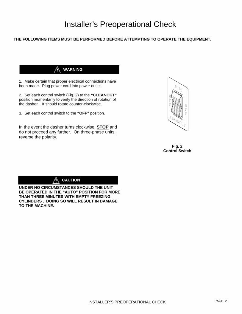
Fig. 2 Control Switch
1. Make certain that proper electrical connections have been made. Plug power cord into power outlet. 2. Set each control switch (Fig. 2) to the “CLEANOUT” position momentarily to verify the direction of rotation of the dasher. It should rotate counter-clockwise. 3. Set each control switch to the “OFF” position. In the event the dasher turns clockwise, STOP and do not proceed any further. On three-phase units, reverse the polarity.
WARNING
UNDER NO CIRCUMSTANCES SHOULD THE UNIT BE OPERATED IN THE “AUTO” POSITION FOR MORE THAN THREE MINUTES WITH EMPTY FREEZING CYLINDERS . DOING SO WILL RESULT IN DAMAGE TO THE MACHINE.
CAUTION

Disassembly and Cleaning Procedure 1. Fill the machine with cold water and set the control switches to the “CLEANOUT” position. DO NOT use hot water which could damage the machine. Let the machine agitate briefly and drain the water by pulling downward on the spigot handle. Repeat the above procedure as necessary to make certain all product is removed from the machine. After the machine is empty, set each control switch to the “OFF” position. 2. Prepare a suitable detergent and water solution at a temperature of 125°F. to 130°F. DO NOT use an abrasive detergent on any part of the dispenser.
DO NOT USE HOT WATER. DOING SO MAY DAMAGE THE MACHINE.
3. Fill each mix pan with the cleaning solution. Make certain that the machine is “OFF”. Clean the mix pans thoroughly with a brush as the solution drains into the freezing cylinders. Clean the mix inlet tubes and the carburetor tube holes with the brush provided.
Emptying Machine Prior to the disassembly and cleaning of parts, the machine must be emptied of product. Use the following procedures (Steps 1 through 3). If this is first time operation, disregard these steps.
DO NOT INSERT ANY OBJECTS OR TOOLS INTO THE MIX INLET HOLE, CARBURETOR TUBE HOLE, OR FRONT PLATE DISPENSING HOLE WHILE THE MACHINE IS RUNNING. DAMAGE TO THE MACHINE OR PERSONAL INJURY MAY RESULT. 1. Remove the carburetor tubes (Fig. 5) from the mix inlet holes and lay in the bottom of the mix pans. 2. Set each control switch (Fig. 2) to the “CLEANOUT” position and dispense all product from the freezing cylinder by pulling downward on the spigot handle (Fig. 6) to empty the machine. 3. Set each control switch to the “OFF” (center) position. Close the spigot handles before proceeding to cleaning.
CONSULT YOUR LOCAL HEALTH AGENCY FOR LOCAL CLEANING AND SANITIZING REQUIREMENTS. This unit does not come pre-sanitized from the factory. Before serving product, the dispenser must be disassembled, cleaned, lubricated, and sanitized. Please be aware that these instructions are general guidelines. Cleaning and sanitizing procedures must conform to local Health Authority requirements.
DISASSEMBLY & CLEANING PAGE 3
Fig. 6 Dispensing Product
CAUTION
CAUTION
Disassembly and Cleaning
Fig. 5 Carburetor Tube

IMPORTANT
4. Set each control switch (Fig. 2) to the “CLEANOUT” position and agitate for approximately 1 - 2 minutes and then drain the water by opening the spigots (Fig. 6). After the unit is empty, set the control switches to the “OFF” position. 5. Remove the front plate by turning the four black plastic knobs in a counterclockwise direction (Fig. 7). 6. Disassemble the front plate in the following manner: a. Remove the pivot rod and spigot handles. b. Push the spigot plungers out of the top of the front
plate assembly. c. Remove both front plate gaskets by placing your
thumb and forefinger as shown in Fig. 8 and squeeze until a loop is formed. Then roll each gasket out of its groove.
d. Remove the o-rings from the spigot plungers by grasping the part with one hand and with a dry cloth in the other hand, squeeze each o-ring upward. When a loop is formed, grasp the o-ring with the other hand and roll it out of its groove and off of the part (Fig. 9).
DO NOT USE ANY TOOLS OR SHARP OBJECTS TO REMOVE ANY O-RINGS FROM THIS MACHINE. SHARP OBJECTS WILL DAMAGE THE O-RINGS.
DISASSEMBLY & CLEANING
Fig. 8 Front Plate Gasket Removal
Fig. 9 Spigot Plunger O-ring Removal
PAGE 4
Fig. 7 Front Plate Assembly
Pivot Rod
Spigot Handles
Spigot Plungers
Spigot Plunger O-rings
Front Plate Gaskets
Knobs

7. Remove the dasher assemblies (Fig. 10) being careful not to damage the scraper blades.
a. For 501 and 527 models only: Remove the blades
and blade holders from the dasher assemblies - Fig 10a - by rotating the blades downward, then by pulling the short pins out of the rear supports. Slide the scraper blades off of the scraper blade holders. b. For 522 models only: Remove the blades and blade
holders from the dasher assemblies - Fig 10b - by rotating the front blades downward, then by pulling the short pins out of the center supports. To remove the rear blades, rotate the blades downward, then pull the short pins out of the rear supports. Slide the scraper blades off of the scraper blade holders.
BLADES MUST BE REMOVED FOR CLEANING. c. Remove and take apart the two piece rear seal
assemblies shown below. d. Remove the stator rods from the dashers.
8. Remove the carburetor tubes (Fig. 11) from the mix pans. Disassemble and clean in the following manner: a. Remove the o-rings from the bottom of the insert tube in the same manner as the spigot plunger o-ring removal (Fig. 9). b. Clean the inside of both tubes with the brush provided.
DISASSEMBLY & CLEANING
Fig. 11 Carburetor Tube
PAGE 5
Fig. 10(a) 501 & 527 Dasher Assembly
Fig. 10(b) 522 Dasher Assembly
Scraper Blade
Long Pin
Rear Seal
Short Pin
Rear Bearing
Flow Plate
Stator Rod Auger
Short Pin
Rear Seal Rear Bearing
Auger Center Support Flow Plate
Stator Rod
Scraper Blade
Long Pin
IMPORTANT
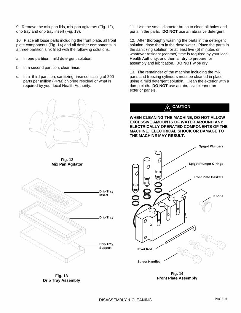
11. Use the small diameter brush to clean all holes and ports in the parts. DO NOT use an abrasive detergent. 12. After thoroughly washing the parts in the detergent solution, rinse them in the rinse water. Place the parts in the sanitizing solution for at least five (5) minutes or whatever resident (contact) time is required by your local Health Authority, and then air dry to prepare for assembly and lubrication. DO NOT wipe dry. 13. The remainder of the machine including the mix pans and freezing cylinders must be cleaned in place using a mild detergent solution. Clean the exterior with a damp cloth. DO NOT use an abrasive cleaner on exterior panels.
WHEN CLEANING THE MACHINE, DO NOT ALLOW EXCESSIVE AMOUNTS OF WATER AROUND ANY ELECTRICALLY OPERATED COMPONENTS OF THE MACHINE. ELECTRICAL SHOCK OR DAMAGE TO THE MACHINE MAY RESULT.
9. Remove the mix pan lids, mix pan agitators (Fig. 12), drip tray and drip tray insert (Fig. 13). 10. Place all loose parts including the front plate, all front plate components (Fig. 14) and all dasher components in a three partition sink filled with the following solutions: a. In one partition, mild detergent solution. b. In a second partition, clear rinse. c. In a third partition, sanitizing rinse consisting of 200
parts per million (PPM) chlorine residual or what is required by your local Health Authority.
DISASSEMBLY & CLEANING PAGE 6
Fig. 13 Drip Tray Assembly
Fig. 12 Mix Pan Agitator
Fig. 14 Front Plate Assembly
Pivot Rod
Spigot Handles
Spigot Plungers
Spigot Plunger O-rings
Front Plate Gaskets
Knobs Drip Tray Insert
Drip Tray
Drip Tray Support
CAUTION
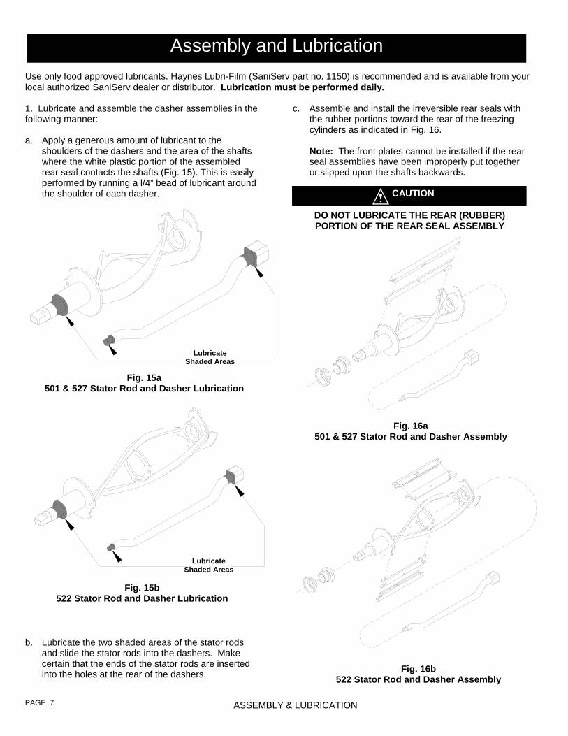
c. Assemble and install the irreversible rear seals with the rubber portions toward the rear of the freezing cylinders as indicated in Fig. 16.
Note: The front plates cannot be installed if the rear
seal assemblies have been improperly put together or slipped upon the shafts backwards.
DO NOT LUBRICATE THE REAR (RUBBER) PORTION OF THE REAR SEAL ASSEMBLY
1. Lubricate and assemble the dasher assemblies in the following manner: a. Apply a generous amount of lubricant to the
shoulders of the dashers and the area of the shafts where the white plastic portion of the assembled rear seal contacts the shafts (Fig. 15). This is easily performed by running a l/4” bead of lubricant around the shoulder of each dasher.
b. Lubricate the two shaded areas of the stator rods
and slide the stator rods into the dashers. Make certain that the ends of the stator rods are inserted into the holes at the rear of the dashers.
Use only food approved lubricants. Haynes Lubri-Film (SaniServ part no. 1150) is recommended and is available from your local authorized SaniServ dealer or distributor. Lubrication must be performed daily.
ASSEMBLY & LUBRICATION PAGE 7
Fig. 15a 501 & 527 Stator Rod and Dasher Lubrication
Fig. 15b 522 Stator Rod and Dasher Lubrication
Fig. 16b 522 Stator Rod and Dasher Assembly
Fig. 16a 501 & 527 Stator Rod and Dasher Assembly
Lubricate Shaded Areas
Lubricate Shaded Areas
CAUTION
Assembly and Lubrication

2. Lubricate and assemble the front plate assembly in the following manner: a. Install the two o-rings on each spigot plunger
(double o-ring on the plunger with vertical grooves) by rolling them onto the plunger. Seat the o-rings in the grooves making certain that they are not twisted. Smooth the lubricant into the grooves and over the sides of the plunger assemblies (Fig. 19).
b. Slide the lubricated spigot plungers into the front plate (Fig. 20) making certain that the spigot handle slots are aligned to the front of the front plate. The spigot plunger with the double o-ring must be installed in the center cylinder of the front plate.
C. Insert the spigot handles and secure them with the
pivot rod.
d. Place the scraper blades over the scraper blade holders so the holder pins fit into the blade notches as shown in Fig. 17.
e. With the front of
each dasher facing the installer, slide the scraper blade holder (Long pin to front) forward into the front of the dasher. Push the short pin back into the mating hole in the rear of the dasher assembly. This procedure must be performed with the blade in the correct position - Fig. 18 Position A. Then rotate the blade and lock it into place (Fig. 18 Position B).
On model 522 repeat this procedure to mount the
rear blades between the center and the rear of the dasher assemblies.
f. Insert the dasher assemblies into the freezing cylinders as far as possible being careful not to damage the scraper blades.
g. While maintaining force against each dasher, rotate
it slowly until the tongue of the dasher engages the groove in the drive system at the rear of each freezing cylinder. The outermost portion of each dasher should be recessed approximately 1/4” to 1/8” inside each freezing cylinder. No part of the dashers should extend out side of the cylinders.
ASSEMBLY & LUBRICATION PAGE 8
Fig. 18 Dasher (Front View)
Fig. 17 Scraper Blade Assembly
Fig. 19 Spigot Plunger Lubrication
Pivot Rod
Spigot Handles
Spigot Plungers
Spigot Plunger O-rings
Front Plate Gaskets
Knobs
Position A Position B
Holder Pin
Notch
Blade Assembly
Scraper Blade Holder
Scraper Blade
Lubricate Shaded Area

3. Install the o-ring on each carburetor tube (Fig. 23). Apply a lubricant (SaniGel p/n 1150 recommended) sparingly over the o-rings. Place the carburetor tubes in the bottom of the mix pans for sanitizing. Be certain that lubricant does not block the mix inlet hole on the carburetor tube. 4. Apply a small amount of lubricant to the bottom of the mix pan agitator. Place the lubricated mix pan agitator into the right front corner of the mix pan. Position the mix pan agitator until you feel the magnets of the agitator engage the magnets of the drive system beneath the mix pan. DO NOT apply lubrication to the Mixout probe located in the mix pan.
d. Install the blue gaskets by slipping them into the grooves in the front plate as shown in Fig. 21. Install so that the thicker edge of the gasket is next to the rear of the front plate. Then lubricate the outside tapered edge of the gaskets.
e. Apply lubricant to the bottom of each mix pan agitator and place the agitators in the mix pan corners making certain the magnets engage the field of the magnetic drive beneath each mix pan.
f. Install the front plate assembly with the four plastic
knobs. Turn the knobs in a clockwise direction and be certain to tighten them evenly. DO NOT tighten one knob all the way down and then another. Doing so may result in front plate breakage. Only moderate force is required. DO NOT overtighten. Set all spigot plungers to the closed position as shown in Fig. 22.
ASSEMBLY & LUBRICATION
Fig. 21 Front Plate Gasket Installation
Drip Tray Assembly
PAGE 9
Fig. 22 Front Plate Assembly
Drip Tray Insert
Drip Tray
Drip Tray Support
Fig. 23 Carburetor
Tube
Lubricate O-Ring
Mix Pan Agitator
Carburetor Tube
Carburetor Tube O-ring
Fig. 24 Mix Pan Components

1. First, wash hands with a suitable antibacterial soap. 2. Prepare approximately 2 - 3 gallons of sanitizing solution equivalent to 200 ppm chlorine residual or what is required by your local Health Authority. 3. Pour the solution into the mix pans. 4. Using a sanitary brush, wipe the solution onto the undersides of the mix pan lids, the sides of the mix pans, and over the mixout probes (Fig. 25). 5. Set each control switch (Fig. 26) to the bottom “CLEANOUT” position and let the unit agitate for approximately three to five minutes. NOTE: DO NOT set the control switches to the top “AUTO” position. Doing so would freeze the sanitizing solution and may result in damage to the machine.
DO NOT INSERT ANY TOOLS OR OBJECTS INTO THE MIX INLET HOLES, CARBURETOR TUBE HOLES, OR THE DISPENSING HOLES IN THE
FRONT PLATE. DAMAGE TO THE MACHINE OR PERSONAL INJURY MAY RESULT.
6. Set each control switch (Fig. 26) to the center “OFF” position and drain the solution from the machine. Proceed directly to the “Operation” section of this manual. DO NOT RINSE OUT THE MACHINE
Prior to operation, the machine must be sanitized. The unit must have already been cleaned and lubricated. Note: Sanitize immediately before use, not several hours before or the previous evening.
Always start with a cleaned and sanitized dispenser as per previous instructions. Use only fresh mix when charging the units. Following these instructions is critical to the maximum operating efficiency of the machine.
1. Remove the carburetor tubes from the bottom of the mix pans and set aside in a sanitary location. 2. Place a 16 oz. Cup under the spigot and open the spigot handle. Pour approximately one quart of fresh product mix into the mix pan. (This will chase the sanitizing solution from the mix pan and freezing cylinder.) Close the spigot handle when the sanitizer is purged from the system. 3. Close all spigot plungers and add mix until the freezing cylinders stop bubbling.
SANITIZING & OPERATION PAGE 10
Mixout Probe
Fig. 26 Control Switch
Fig. 25 Mix Pan Reservoir Mixout Probe
CAUTION
Sanitizing
Operation
Fig. 27 Dispensing Product
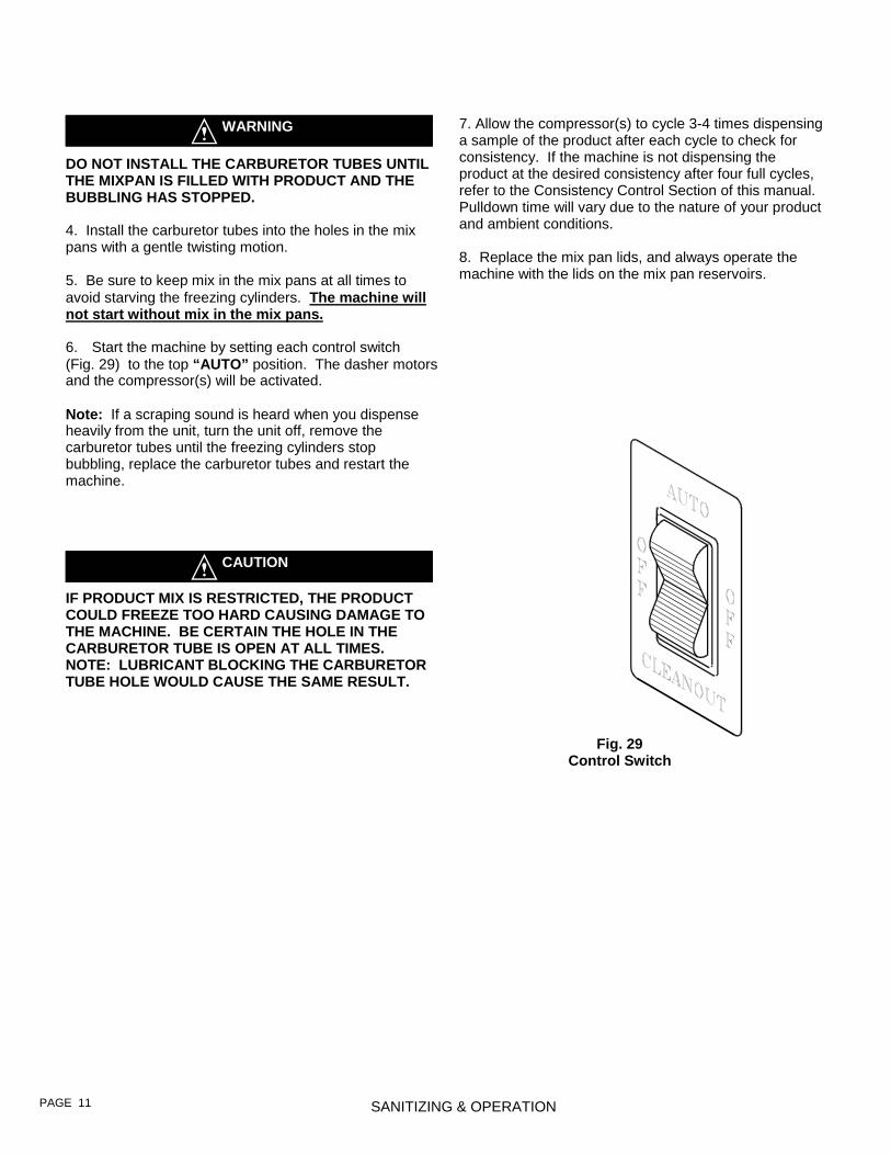
DO NOT INSTALL THE CARBURETOR TUBES UNTIL THE MIXPAN IS FILLED WITH PRODUCT AND THE BUBBLING HAS STOPPED. 4. Install the carburetor tubes into the holes in the mix pans with a gentle twisting motion. 5. Be sure to keep mix in the mix pans at all times to avoid starving the freezing cylinders. The machine will not start without mix in the mix pans. 6. Start the machine by setting each control switch (Fig. 29) to the top “AUTO” position. The dasher motors and the compressor(s) will be activated. Note: If a scraping sound is heard when you dispense heavily from the unit, turn the unit off, remove the carburetor tubes until the freezing cylinders stop bubbling, replace the carburetor tubes and restart the machine.
IF PRODUCT MIX IS RESTRICTED, THE PRODUCT COULD FREEZE TOO HARD CAUSING DAMAGE TO THE MACHINE. BE CERTAIN THE HOLE IN THE CARBURETOR TUBE IS OPEN AT ALL TIMES. NOTE: LUBRICANT BLOCKING THE CARBURETOR TUBE HOLE WOULD CAUSE THE SAME RESULT.
7. Allow the compressor(s) to cycle 3-4 times dispensing a sample of the product after each cycle to check for consistency. If the machine is not dispensing the product at the desired consistency after four full cycles, refer to the Consistency Control Section of this manual. Pulldown time will vary due to the nature of your product and ambient conditions. 8. Replace the mix pan lids, and always operate the machine with the lids on the mix pan reservoirs.
SANITIZING & OPERATION PAGE 11
Fig. 29 Control Switch
CAUTION
WARNING

Adjustments to the Electronic Consistency Control System can be made by the owner. Should any problems arise when making adjustments, SaniServ recommends that a serviceman trained on SaniServ equipment be contacted. DO NOT attempt to make repairs on the machine. Initial adjustments have been performed at the factory. However, to satisfy individual preferences the following adjustments may be required:
USE EXTREME CAUTION. ELECTRICAL SHOCK HAZARD EXISTS EVEN WHEN THE UNIT IS IN THE “OFF” POSITION. WHEN THE WIRING BOX COVER IS REMOVED, DO NOT TOUCH ANYTHING IN THE WIRING BOX EXCEPT THE POTENTIOMETER. 1. Remove the wiring box cover (Exploded View). 2. Set the control switch to the “AUTO” position. Note: The unit will not operate if the mix pan is empty. 3. Locate the three LED’s - green, yellow, and red - Fig. 29. These are used as a reference point to adjust for proper consistency. Initially, all of the LED’s are off. This indicates that the mix is too thin. The compressor will now come on. As the product thickens, the green, then the yellow, then the red LED illuminate. Two seconds after the red LED is illuminated, the com-pressor and dasher will shut off.
4. Using a small slotted and insulated screwdriver, turn the potentiometer (Fig. 29) clockwise to make the product harder or counterclockwise to make the product softer. Note: The potentiometer is very sensitive. Adjust in small increments 5. Let the compressor and dasher cycle off. Dispense some product. If too thin, turn the potentiometer clockwise. 6. If the product is too thick, turn the potentiometer counterclockwise. Dispense 16 oz. from the barrel. Let the compressor and dasher cycle off 7. Repeat procedure until proper consistency is achieved. Electronic Consistency Control Operation
1. “CLEANOUT” Position: The dasher motor operates continuously, the compressor will not come on. The mix out probe activates the mix out light but will not activate the buzzer. 2. “AUTO” Position: When product is dispensed, the dasher motor will automatically come on and the compressor will run as required by the consistency of the product. The machine will remain running until the product has reached proper consistency, at which time the dasher motor and compressor will stop running. If product has not been dispensed for approximately 10 minutes, the dasher motor will come on and the control board will sense the product consistency. The compressor will come on if required to maintain product consistency. If the product is correct, the dasher motor will stop. When product mix is low in the mix pan, the “mix out” light will flash and the buzzer will beep for three minutes or until the mix pan is filled. If the pan has not been filled by the end of the three minute period, the mix out light will glow continuously, the beeping will become a continuous tone, and the machine will not dispense product until mix is added. NOTE: If product does not freeze to a hard enough consistency, the problem may not be that of the machine. To verify, use a standard thermometer to obtain the temperature of the product. The problem is not in your machine if the product temperature is between 17° and 22° F. Check to see that the product was prepared to the manufacturer’s recommendations.
Electronic Consistency Control System
WARNING
IMPORTANT
CONSISTENCY ADJUSTMENT
Consistency Control Board
Consistency LED’s (Green, Yellow, Red)
Potentiometer
PAGE 13
Fig. 30 Electronic Consistency Control

Routine Maintenance (Owner-Operator)
DISCONNECT THE MACHINE FROM ITS POWER SOURCE(S) BEFORE PERFORMING ANY ROUTINE MAINTENANCE. PERSONAL INJURY OR DAMAGE TO THE MACHINE COULD RESULT IF THIS PRACTICE IS NOT OBSERVED. Daily: Inspect the machine for signs of product leaks past seals and gaskets. If proper assembly does not
HAZARDOUS MOVING PARTS
2. Remove both side panels first, then remove the rear panel of the machine. 3. On the side of the spring adjustment mechanism use a pencil to mark the position of the nut (Fig 31). Relieve the tension on the yellow spring by turning the adjustment screw near the label which warns: DO NOT ADJUST. Disconnect the spring from the belt idler arm by placing needle nose pliers on one end of the spring and pulling the end out of the retainer. 4. Remove the nut from the pivot point of the idler arm assembly. 5. Remove the idler arm and inspect the pivot point sleeve. These areas should be free of rust, debris, or dried lubricant. If any of these substances are found, they must be removed. 6. Clean and polish the sleeve surface with a fine grade of emery cloth. 7. Reinstall the idler arm. 8. Install the belt making certain that there is no grease on the belt or pulleys. Step to the side of the unit and view the belt to determine whether or not it is properly aligned (straight from top to bottom). 9. Install the yellow spring and turn the adjustment screw returning the adjustment nut to the pencil mark you placed on the side of the adjustment mechanism in step 3 above. 10. Repeat steps 3 - 9 for the other side and then place the unit back into operation. Check the product for proper consistency and adjust as required. When the consistency is right, replace the rear and both side panels.
CONDENSER FINS ARE VERY SHARP USE EXTREME CAUTION WHEN CLEANING
Quarterly: Thoroughly clean the condenser fins on all air-cooled machines. Remove all lint and dust with a vacuum cleaner or compressed air to clean fins. A dirty condenser greatly reduces refrigeration capacity and efficiency. When using compressed air, place a damp cloth on the opposite side of the condenser to catch the flying dirt or lint. Annually: Check the belts for signs of wear or cracking. Remove panels and clean all parts inside of the machine including the base, side panels, fan blades, condensers, etc. Semiannually: It is advisable to clean and lubricate the idler arms (Fig. 31) to ensure their smooth operation. Use the following procedures: Note: Twist units have two separate idler arm assemblies (one for each side). For convenience and simplicity, complete the following maintenance on one side of the system before proceeding to the other. 1. Make certain that ALL power to the dispenser is off.
ROUTINE MAINTENANCE
stop leaks around gaskets or seals, check for improper lubrication and worn or damaged parts. Replace parts as needed. Periodically: Inspect the scraper blades to see that they are straight and sharp. If worn, damaged or warped, the blades will not scrape the cylinder walls correctly and the freezing capacity will be reduced. The drip chute assembly which catches seepage from around the rear seal should be cleaned with warm water and detergent solution (Fig. 31).
Fig. 31 Spring Adjustment Mechanism
Drip Chute
Mark Nut Position With Pencil
Idler Arm Pivot
PAGE 13
WARNING WARNING
WARNING
Routine Maintenance (Trained Service Technician)

Helpful Hints Front Plate: This component is the plastic device from which the product is dispensed. It is designed and manufactured for strength and durability. However, through improper use, the front plate can be damaged. Use the following information for proper care: a. Do not over tighten the knobs. b. Always tighten knobs evenly. Do not attempt to turn one knob all the way down and then one of the other three knobs. Doing so will bind the front plate and could result in breakage. c. Improper installation of the stator rods can cause breakage. The stator rods must be properly seated in the dasher before installing the front plate. If the stator rods are improperly installed, subsequent tightening of the knobs will break the front plate. d. DO NOT attempt to wash the front plate or any other components in a dishwasher. Mix Out Light: When the mix out light comes on, the mix pan is low on mix. The mix pan must be filled with fresh product mix immediately to prevent air from entering the freezing cylinder starving the machine and causing freeze-up and vibration. If this condition occurs, set the selector switch to the “OFF” position. Remove the carburetor tube and add mix to the low mix pan until the freezing cylinder stops bubbling. Replace the carburetor tube with a gentle twist, then return the control switch to the “AUTO” position. Filling: Always fill the machine with fresh product at the start of each day. Drip Tray: This should be removed daily and cleaned to remove residue. Mix Pan Lid: Be certain to leave the lid in place on top of the machine to prevent any foreign materials from contaminating the mix. Mixing: Make certain that the product mix is prepared according to label instructions. Sanitizing: Do not soak plastic parts in sanitizer overnight. Doing so can cause the plastic parts to become brittle and lead to premature failure.
Mix Pan Agitator: If the mix pan agitator stops turning during operation of the machine, turn off the machine, reposition the agitator with a sanitized utensil, and follow the instructions for starting the machine. DO NOT POUR SOFT SERVE MIX DIRECTLY ONTO THE AGITATOR WHEN YOU FILL THE MACHINE. Treat the mix pan agitators as any other small parts such as the scraper blades. Follow the same cleaning and sanitizing instructions. Winter Storage: To protect the unit during seasonal shut-down, it is important that the dispenser be stored in the proper manner. Use the following procedures: 1. Turn off ALL power to the machine. 2. Wash all parts that come in contact with the mix with
a warm mild detergent solution. Rinse in clear water and dry parts thoroughly.
3. Store the loose parts such as the mix pan components, front plate parts, and the dasher assembly parts outside of the machine.
4. Do not lay heavy objects on the plastic or rubber parts.
5. Cover the machine and all loose parts to protect them from dust or other contaminants while in storage. Place the machine in a dry location.
6. On water-cooled units, disconnect the water lines. Use compressed air to blow out all remaining water in the condenser. Insert a screwdriver (Fig. 32) to open the water valve. Note: Failure to purge the machine of water can result in severe damage to the cooling system.
HELPFUL HINTS PAGE 14
Fig. 32 Water-Cooled Condenser Valve
PAGE 15 TROUBLESHOOTING GUIDE
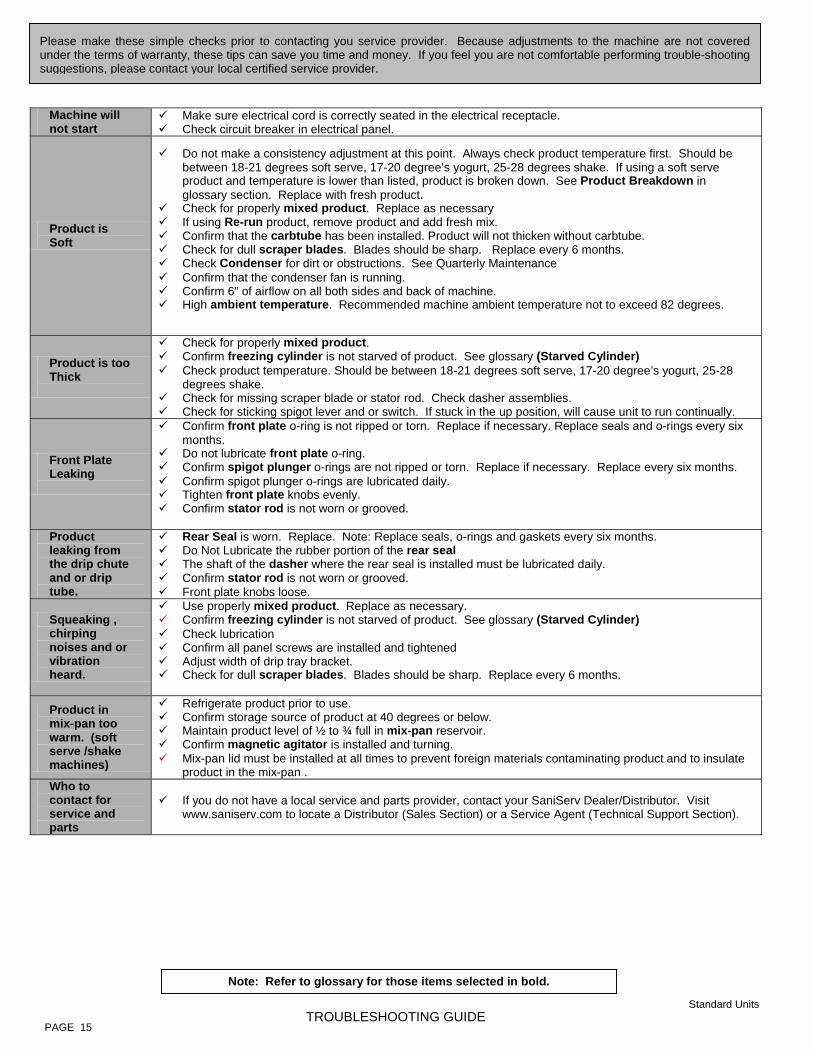
Please make these simple checks prior to contacting you service provider. Because adjustments to the machine are not coveredunder the terms of warranty, these tips can save you time and money. If you feel you are not comfortable performing trouble-shootingsuggestions, please contact your local certified service provider.
Machine will not start
Make sure electrical cord is correctly seated in the electrical receptacle. Check circuit breaker in electrical panel.
Product is Soft
Do not make a consistency adjustment at this point. Always check product temperature first. Should be between 18-21 degrees soft serve, 17-20 degree’s yogurt, 25-28 degrees shake. If using a soft serve product and temperature is lower than listed, product is broken down. See Product Breakdown in glossary section. Replace with fresh product.
Check for properly mixed product. Replace as necessary If using Re-run product, remove product and add fresh mix. Confirm that the carbtube has been installed. Product will not thicken without carbtube. Check for dull scraper blades. Blades should be sharp. Replace every 6 months. Check Condenser for dirt or obstructions. See Quarterly Maintenance Confirm that the condenser fan is running. Confirm 6” of airflow on all both sides and back of machine. High ambient temperature. Recommended machine ambient temperature not to exceed 82 degrees.
Product is too Thick
Check for properly mixed product. Confirm freezing cylinder is not starved of product. See glossary (Starved Cylinder) Check product temperature. Should be between 18-21 degrees soft serve, 17-20 degree’s yogurt, 25-28
degrees shake. Check for missing scraper blade or stator rod. Check dasher assemblies. Check for sticking spigot lever and or switch. If stuck in the up position, will cause unit to run continually.
Front Plate Leaking
Confirm front plate o-ring is not ripped or torn. Replace if necessary. Replace seals and o-rings every six months.
Do not lubricate front plate o-ring. Confirm spigot plunger o-rings are not ripped or torn. Replace if necessary. Replace every six months. Confirm spigot plunger o-rings are lubricated daily. Tighten front plate knobs evenly. Confirm stator rod is not worn or grooved.
Product leaking from the drip chute and or drip tube.
Rear Seal is worn. Replace. Note: Replace seals, o-rings and gaskets every six months. Do Not Lubricate the rubber portion of the rear seal The shaft of the dasher where the rear seal is installed must be lubricated daily. Confirm stator rod is not worn or grooved. Front plate knobs loose.
Squeaking , chirping noises and or vibration heard.
Use properly mixed product. Replace as necessary. Confirm freezing cylinder is not starved of product. See glossary (Starved Cylinder) Check lubrication Confirm all panel screws are installed and tightened Adjust width of drip tray bracket. Check for dull scraper blades. Blades should be sharp. Replace every 6 months.
Product in mix-pan too warm. (soft serve /shake machines)
Refrigerate product prior to use. Confirm storage source of product at 40 degrees or below. Maintain product level of ½ to ¾ full in mix-pan reservoir. Confirm magnetic agitator is installed and turning. Mix-pan lid must be installed at all times to prevent foreign materials contaminating product and to insulate
product in the mix-pan . Who to contact for service and parts
If you do not have a local service and parts provider, contact your SaniServ Dealer/Distributor. Visit www.saniserv.com to locate a Distributor (Sales Section) or a Service Agent (Technical Support Section).
Note: Refer to glossary for those items selected in bold.
Standard Units

PAGE 16 TROUBLESHOOTING GLOSSARY
Trouble Shooting Glossary Ambient Temperature. The temperature of the air in the immediate vicinity of the operating machine. High ambi-ent temperature can reduce the capacity with an air-cooled condenser. Capacity. The total capacity of frozen product that a freezer can produce in a given period usually stated in gal-lons per hour (G.P.H.). Carbtube. Flow control device that allows product and air to be blended together. The air added to the product is labeled as over-run. The over-run helps provide a thick and rich product. If the carbtube is not used the product will be heavy, wet, grainy, will not thicken and product temperatures will be lower than the specified 18-21 degrees soft serve and 25-28 degrees shake. Condenser. The part of the refrigeration mechanism that receives hot, high-pressure refrigeration gas from the compressor and cools gaseous refrigerant until it returns to a liquid state. Consistency. The viscosity or thickness of the product in the freezing cylinder. Consistency Control. A control that senses the thickness or viscosity of the product in the freezing cylinder. Dasher. The part of the freezer that scrapes frozen product off the inside of the freezing cylinder and blends the product. In a gravity freezer, this assembly also moves the product forward to be dispensed. Front Plate. Seals the front of the freezing cylinder and provides a means for dispensing the product. On gravity fed freezers, the front plate indirectly holds the dasher in place via the stator rod. It also provides compression for the rear seal. Freezing Cylinder. The part of the refrigeration mechanism in which the refrigerant vaporizes and absorbs heat. This is the part of the freezer where the liquid product is frozen. Magnetic Agitator. Installed in the mix-pan reservoir and used to maintain product temperatures and prevent product separation. The bottom of the agitator must be lubricated. Mix-pan. Is the top container that product is poured into. It is used as storage until product is needed for the freezing cylinder. Soft Serve and Shake machines have refrigerated mix-pans to prevent bacteria from forming. Mixing Product / Product Temperatures. If your using a product that has to be mixed with water or other ingredi-ents, it is imperative the product is mixed consistently everyday. If not, the machine will not run consistent and could possibly damage components. This is very important with frozen (slush) beverages. Always mix to the product manufactures recommendations. The machine is designed to operate with a frozen product that falls within these temperatures (soft serve 18-21 degrees, yogurt 17-20 degrees, shake 25-28 degrees). Overrun. The volumetric increase of product from the liquid to the solid state due to the incorporation of air into the frozen product. Overrun is states as a percentage. Product Breakdown. The decline in frozen product quality resulting from excess agitation or temperature varia-tions of product that has been in the freezing cylinder too long. Product, which has broken down, may be grainy, wet and or heavy. Product breakdown is easily detected by taking the temperature of the dispensed product. Temperatures will always be lower than recommended product temperatures.

PAGE 17 TROUBLESHOOTING GLOSSARY
Trouble Shooting Glossary Rear Seal. This part is stationary during operation and must not move. When installed and lubed properly, seals mix in cylinder. When installed and lubed improperly, it causes main shafted bearing failure. Regulator. Used to control the rate of water or CO2 P.S.I.. Rerun. The reuse of previously frozen product after it has melted to a liquid. Rerun is obtained when emptying a freezer for periodic cleaning. Use caution when using rerun as it may contain high bacteria or Coli count, which could contaminate the fresh mix with which it is combined. Freezers should never be started with rerun. If used at all, it should be blended with fresh mix at a ratio of seven parts new mix with three parts old mix, after initial freeze-down with fresh mix. Scraper Blades. The component that scrapes the frozen product from the freezing cylinder surface. Blades must be sharp, as dull blades will leave product on the freezing cylinder, insulating the mix from the refrigerant. Spinner Assembly. An externally installed or internally installed component used to blend a base product with flavoring or other particulate. Spigot Plunger. The mechanism on the front plate through which the product is dispensed. Starved Cylinder. A starved cylinder is often mistaken for a freeze up or product too thick. A starved cylinder (starving) is created when a larger percentage of frozen product is dispensed from the freezing cylinder than the percentage of liquid product entering the freezing cylinder from the mix-pan. There are several causes of starving. 1. Overdrawing: Dispensing more product from the machine than it’s designed to do. This would occur if a ma-
chine were undersized for its application. 2. Inserting the carbtube prior to pouring the initial product into the mix-pan at the start of each day. This forms a
vacuum and traps a large percentage of air in the cylinder; therefore the cylinder will not fill with product. 3. When carbtube hole setting is not set on the correct hole size for the amount of product being drawn. Exam-
ple, if several customer dispense product from the machine with the carbtube set on the small hole, it will not allow the freezing cylinder to be replenished with product in a timely manner. Change carbtube setting to a larger hole.
4. Carbtube not being cleaned, thus allowing product build-up in the carbtube holes. This restricts product from entering the freezing cylinder.
5. Mix out light not working therefore not alerting operator the need to add product. 6. Pouring frozen or semi frozen product into the mix-pan reservoir. This will form a blockage in the carbtube
hole and not allow liquid product to flow into the cylinder. 7. Mix-pan too cold, allowing product to freeze in mix-pan and restricting product flow. Stator Rod. Acts as a bearing surface. Helps enfold air for overrun. Transmits compression to the rear seal. Helps mechanical torque system sense torque. Be sure to lubricate.

Date Service Performed Service Performed By
SERVICE RECORD PAGE 18
Service Record

This page intentionally blank.

This page intentionally blank.

Proudly made in the U.S.A.
Technical Publication 82023
Updated 05/06
451 E. County Line Road P.O. Box 1089
Mooresville, Indiana 46158-5089
SaniServ® An AFFINIS GROUP Company
We are on the web... www.saniserv.com